


MAKING MODERN LIVING POSSIBLE
Operating Instructions
VLT® AQUA Drive FC 202
110–1400 kW
www.danfoss.com/drives


Contents VLT AQUA Drive FC 202 Operation Instructions
Contents
1 How to Read these Operating Instructions
2 Safety
2.1 Safety Note
2.1.1 General Warning 6
2.1.2 Before Commencing Repair Work 7
2.1.3 Special Conditions 7
2.1.4 Avoid Unintended Start 7
2.1.5 Safe Torque Off (STO) 7
2.1.6 IT Mains 8
3 How to Install
3.1 How to Get Started
3.2 Pre-installation
3.2.1 Planning the Installation Site 9
3.2.2 Receiving the Frequency Converter 10
3.2.3 Transportation and Unpacking 10
3.2.4 Lifting 10
4
6
6
9
9
9
3.2.5 Mechanical Dimensions 12
3.2.6 Rated Power 18
3.3 Mechanical Installation
3.3.1 Tools Needed 20
3.3.2 General Considerations 20
3.3.3 Terminal Locations - Enclosure Type D 21
3.3.4 Terminal Locations - E Enclosures 24
3.3.5 Terminal Locations - Enclosure type F 29
3.3.6 Cooling and Airflow 33
3.3.7 Installation on the Wall - IP21 (NEMA 1) and IP54 (NEMA 12) Units 35
3.3.8 Gland/Conduit Entry - IP21 (NEMA 1) and IP54 (NEMA12) 35
3.3.9 IP21 Drip Shield Installation (Enclosure Types D1 and D2) 37
3.4 Field Installation of Options
3.4.1 Installation of Duct Cooling Kit in Rittal Enclosures 37
3.4.2 Outside Installation/NEMA 3R Kit for Rittal Enclosures 38
3.4.3 Installation on Pedestal 39
3.4.4 Installation of Input Plate Options 40
20
37
3.4.5 Installation of Mains Shield for Frequency Converters 41
3.5 Enclsoure Type F Panel Options
3.5.1 Enclsoure Type F Options 41
3.6 Electrical Installation
3.6.1 Power Connections 42
MG20P402 - Rev. 2013-12-16 1
41
42

Contents VLT AQUA Drive FC 202 Operation Instructions
3.6.2 Grounding 53
3.6.3 Extra Protection (RCD) 53
3.6.4 RFI Switch 53
3.6.5 Torque 53
3.6.6 Shielded Cables 54
3.6.7 Motor Cable 54
3.6.8 Brake Cable for Frequency Converters with Factory Installed Brake Chopper Option 55
3.6.9 Brake Resistor Temperature Switch 55
3.6.10 Load Sharing 55
3.6.11 Shielding against Electrical Noise 55
3.6.12 Mains Connection 56
3.6.13 External Fan Supply 56
3.6.14 Fuses 56
3.6.15 Mains Disconnectors 59
3.6.16 F Enclosure Circuit Breakers 59
3.6.17 F Enclosure Mains Contactors 60
3.6.18 Motor Insulation 60
3.6.19 Motor Bearing Currents 60
3.6.20 Control Cable Routing 60
3.6.21 Access to Control Terminals 62
3.6.22 Electrical Installation, Control Terminals 62
3.6.23 Electrical Installation, Control Cables 63
3.6.24 Switches S201, S202, and S801 65
3.7 Connection Examples
3.7.1 Start/Stop 66
3.7.2 Pulse Start/Stop 66
3.8 Final Set-up and Test
3.9 Additional Connections
3.9.1 Mechanical Brake Control 68
3.9.2 Parallel Connection of Motors 68
3.9.3 Motor Thermal Protection 69
66
67
68
4 How to operate the frequency converter
4.1 Ways of Operation
4.1.1 How to operate graphical LCP (GLCP) 70
4.1.2 How to Operate Numeric LCP (NLCP) 73
4.1.3 Changing Data 75
4.1.4 Changing a Text Value 75
4.1.5 Changing a Group of Numeric Data Values 75
4.1.6 Changing of Data Value, Step-by-Step 76
2 MG20P402 - Rev. 2013-12-16
70
70

Contents VLT AQUA Drive FC 202 Operation Instructions
4.1.7 Read-out and Programming of Indexed Parameters 76
4.1.8 Tips and Tricks 76
5 How to programme the frequency converter
5.1 How to programme
5.2 Commonly Used Parameters - Explanations
5.3 Parameter Menu Structure
6 General Specifications
7 Troubleshooting
Index
79
79
84
112
117
130
142
MG20P402 - Rev. 2013-12-16 3

How to Read these Operating... VLT AQUA Drive FC 202 Operation Instructions
1
1 How to Read these Operating Instructions
notice or any obligation to notify former or present users
VLT AQUA Drive
FC 200 Series
Software version: 2.1x
This guide can be used with all FC
202 frequency converters with
software
version 2.1x or later.
The actual software version
number can be read from
15-43 Software Version.
This publication contains information proprietary to
Danfoss. By accepting and using this manual the user
agrees that the information contained herein is used solely
for operating equipment from Danfoss or equipment from
other vendors if such equipment is intended for communication with Danfoss equipment over a serial
communication link. This publication is protected under
the Copyright laws of Denmark and most other countries.
Danfoss does not warrant that a software program
produced according to the guidelines provided in this
manual functions properly in every physical, hardware or
software environment.
Although Danfoss has tested and reviewed the documentation within this manual, Danfoss makes no warranty or
representation, neither expressed nor implied, with respect
to this documentation, including its quality, performance,
or fitness for a particular purpose.
In no event shall Danfoss be liable for direct, indirect,
special, incidental, or consequential damages arising out of
the use, or the inability to use information contained in
this manual, even if advised of the possibility of such
damages. In particular, Danfoss is not responsible for any
costs, including but not limited to those incurred as a
result of lost profits or revenue, loss or damage of
equipment, loss of computer programs, loss of data, the
costs to substitute these, or any claims by third parties.
of such revisions or changes.
1.1.1 Available Literature
•
•
•
•
•
•
•
•
•
•
•
•
•
•
•
Danfoss technical literature is also available online at
www.danfoss.com/BusinessAreas/DrivesSolutions/
Documentations/Technical+Documentation.htm.
VLT® AQUA Drive FC 202 Operating Instructions
provide the neccessary information for getting
the frequency converter up and running.
VLT® AQUA Drive FC 202, 110-1400 kW Operating
Instructions provide the neccessary information
for getting the high power frequency converter
up and running.
®
VLT
AQUA Drive FC 202 Design Guide entails all
technical information about the frequency
converter and customer design and applications.
®
VLT
AQUA Drive FC 202 Programming Guide
provides information on how to programme and
includes complete parameter descriptions.
VLT® AQUA Drive FC 202 Profibus
®
VLT
AQUA Drive FC 202 DeviceNet
Output Filters Design Guide
VLT® AQUA Drive FC 202 Cascade Controller
Application Note MN20A: Submersible Pump
Application
Application Note MN20: Master/Follower Operation
Application
Application Note MN20F: Drive Closed Loop and
Sleep Mode
Installation Instruction for Mounting Brackets
Enclosure type A5, B1, B2, C1 and C2 IP21, IP55 or
IP66
Instruction for Analog I/O Option MCB109
Instruction for Panel through mount kit
®
Active Filter Operating Instruction
VLT
Danfoss reserves the right to revise this publication at any
time and to make changes to its contents without prior
4 MG20P402 - Rev. 2013-12-16

How to Read these Operating... VLT AQUA Drive FC 202 Operation Instructions
The frequency converter complies with UL508C thermal
memory retention requirements. For more information,
refer to the section Motor Thermal Protection in the Design
Guide.
NOTICE
Imposed limitations on the output frequency
(due to export control regulations):
From software version 6.72 the output frequency of the
frequency converter is limited to 590 Hz. Software
versions 6x.xx also limit the maximum output frequency
to 590 Hz, but these versions cannot be flashed, i.e.
neither downgraded nor upgraded.
The following symbols are used in this document:
WARNING
Indicates a potentially hazardous situation which could
result in death or serious injury.
1
1
CAUTION
Indicates a potentially hazardous situation which could
result in minor or moderate injury. It may also be used
to alert against unsafe practices.
NOTICE
Indicates important information, including situations that
may result in damage to equipment or property.
MG20P402 - Rev. 2013-12-16 5

Safety VLT AQUA Drive FC 202 Operation Instructions
2 Safety
22
2.1 Safety Note
WARNING
The voltage of the frequency converter is dangerous
whenever connected to mains. Incorrect installation of
the motor, frequency converter or fieldbus may cause
damage to the equipment, serious personal injury or
death. Consequently, the instructions in this manual, as
well as national and local rules and safety regulations,
must be complied with.
Safety Regulations
1. The frequency converter must be disconnected
from mains if repair work is to be carried out.
Check that the mains supply has been disconnected and that the necessary time has passed
before removing motor and mains plugs.
2. The [STOP/RESET] key on the control panel of the
frequency converter does not disconnect the
equipment from mains and is thus not to be used
as a safety switch.
3. Correct protective earthing of the equipment
must be established, the user must be protected
against supply voltage, and the motor must be
protected against overload in accordance with
applicable national and local regulations.
4. The earth leakage currents are higher than 3.5
mA.
5. Protection against motor overload is set by par.
1-90 Motor Thermal Protection. If this function is
desired, set par. 1-90 to data value [ETR trip]
(default value) or data value [ETR warning]. Note:
The function is initialised at 1.16 x rated motor
current and rated motor frequency. For the North
American market: The ETR functions provide class
20 motor overload protection in accordance with
NEC.
6. Do not remove the plugs for the motor and
mains supply while the frequency converter is
connected to mains. Check that the mains supply
has been disconnected and that the necessary
time has passed before removing motor and
mains plugs.
7. Note that the frequency converter has voltage
inputs other than L1, L2 and L3, when load
sharing (linking of DC intermediate circuit) and
external 24 V DC have been installed. Check that
all voltage inputs have been disconnected and
that the necessary time has passed before
commencing repair work.
NOTICE
Installation at high altitude:
380 - 480 V: At altitudes above 3,000 m, contact Danfoss
regarding PELV.
525 - 690 V: At altitudes above 2,000 m, contact Danfoss
regarding PELV.
Warning against Unintended Start
1. The motor can be stopped with digital
commands, bus commands, references or a local
stop, while the frequency converter is connected
to mains. To avoid personal injury, these stop
functions are not sufficient to ensure that no
unintended start occurs.
2. While parameters are being changed, the motor
may start. Consequently, always press [RESET];
following which data can be modified.
3. A motor that has been stopped may start if faults
occur in the electronics of the frequency
converter, or if a temporary overload or a fault in
the supply mains or the motor connection ceases.
WARNING
Warning:
Touching the electrical parts may be fatal - even after
the equipment has been disconnected from mains.
Also make sure that other voltage inputs have been
disconnected, such as external 24 V DC, load sharing
(linkage of DC intermediate circuit), as well as the motor
connection for kinetic back-up.
General Warning
2.1.1
WARNING
Warning:
Touching the electrical parts may be fatal - even after
the equipment has been disconnected from mains.
Also make sure that other voltage inputs have been
disconnected, (linkage of DC intermediate circuit), as well
as the motor connection for kinetic back-up.
Before touching any potentially live parts of the
frequency converter, wait at least as follows: Be aware
that there may be high voltage on the DC link even
when the Control Card LEDs are turned off. A red LED is
mounted on a circuit board inside the frequency
converter to indicate the DC bus voltage. The red LED
stays lit until the DC link is 50 V DC or lower.
6 MG20P402 - Rev. 2013-12-16

Safety
VLT AQUA Drive FC 202 Operation Instructions
WARNING
Leakage Current
The earth leakage current from the frequency converter
exceeds 3.5 mA. According to IEC 61800-5-1 a reinforced
Protective Earth connection must be ensured by means
of: a min. 10mm² Cu or 16mm² Al PE-wire or an
addtional PE wire - with the same cable cross section as
the Mains wiring - must be terminated separately.
Residual Current Device
This product can cause a D.C. current in the protective
conductor. Where a residual current device (RCD) is used
for extra protection, only an RCD of Type B (time
delayed) shall be used on the supply side of this
product. See also RCD Application Note MN.90.GX.02.
Protective earthing of the frequency converter and the
use of RCD's must always follow national and local
regulations.
Grid configuration (IT,TN, grounded leg, etc.)
•
Safety of low-voltage ports (PELV conditions)
•
Consult the relevant clauses in these instructions and in
the Design Guide for information about the installation
requirements.
WARNING
The frequency converter's DC link capacitors remain
charged after power has been disconnected. To avoid an
electrical shock hazard, disconnect the frequency
converter from the mains before carrying out
maintenance. Before doing service on the frequency
converter, wait at least the amount of time indicated
below:
Voltage Power size
Min. Waiting Time
2 2
Before Commencing Repair Work
2.1.2
1. Disconnect the frequency converter from mains.
2. Disconnect DC bus terminals 88 and 89.
3.
Wait at least the time mentioned in
chapter 2.1.1 General Warning.
Special Conditions
2.1.3
Electrical ratings
The rating indicated on the nameplate of the frequency
converter is based on a typical 3-phase mains power
supply, within the specified voltage, current and
temperature range, which is expected to be used in most
applications.
The frequency converters also support other special
applications, which affect the electrical ratings of the
frequency converter. Special conditions which affect the
electrical ratings might be:
Single phase applications
•
High temperature applications which require
•
derating of the electrical ratings
Marine applications with more severe environ-
•
mental conditions.
Consult the relevant clauses in these instructions and in
the Design Guide for information about the electrical
ratings.
Installation requirements
The overall electrical safety of the frequency converter
requires special installation considerations regarding:
Fuses and circuit breakers for over-current and
•
short-circuit protection
Selection of power cables (mains, motor, brake,
•
loadsharing and relay)
380 - 480 V 110 - 250 kW 20 minutes
315 - 1000 kW 40 minutes
525 - 690 V 45 - 400 kW 20 minutes
450- 1400 kW 30 minutes
Be aware that there may be high voltage on the DC link even
when the LEDs are turned off.
Table 2.1 Discharge Time
Avoid Unintended Start
2.1.4
WARNING
While the frequency converter is connected to mains, the
motor can be started/stopped using digital commands,
bus commands, references or via the Local Control Panel.
Disconnect the frequency converter from mains
•
whenever personal safety considerations make
it necessary to avoid unintended start.
To avoid unintended start, always activate the
•
[Off] key before changing parameters.
Unless terminal 37 is turned off, an electronic
•
fault, temporary overload, a fault in the mains
supply, or lost motor connection may cause a
stopped motor to start.
Safe Torque Off (STO)
2.1.5
To run Safe Torque Off, additional wiring for the frequency
converter is required, refer to Safe Torque Off Operating
Instructions for Danfoss VLT® Frequency Converters for
further information.
MG20P402 - Rev. 2013-12-16 7

Safety VLT AQUA Drive FC 202 Operation Instructions
2.1.6 IT Mains
22
WARNING
IT mains
Do not connect frequency converters with RFI-filters to
mains supplies with a voltage between phase and earth
of more than 440 V for 400 V converters and 760 V for
690 V converters.
For 400 V IT mains and delta earth (grounded leg), mains
voltage may exceed 440 V between phase and earth.
For 690 V IT mains and delta earth (grounded leg), mains
voltage may exceed 760 V between phase and earth.
Failure to follow recommendations could result in death
or serious injury.
14-50 RFI Filter can be used to disconnect the internal RFI
capacitors from the RFI filter to ground.
Disposal Instruction
2.1.7
Equipment containing electrical components
must not be disposed of together with
domestic waste.
It must be separately collected with electrical
and electronic waste according to local and
currently valid legislation.
8 MG20P402 - Rev. 2013-12-16

M
3
96 97 9998
37
91 92 93
12
L1
W PEVU
F1
L2
L3
PE
130BA015.13
1
18
81 82
R+R-
95
55
50
53
27
88
89
DC- DC+
L1 L2 PEL3
How to Install
3 How to Install
3.1 How to Get Started
VLT AQUA Drive FC 202 Operation Instructions
This chapter covers mechanical and electrical installations
to and from power terminals and control card terminals.
Electrical installation of options is described in the relevant
Operating Instructions and Design Guide.
The frequency converter is designed to achieve a quick
and EMC-correct installation by following the steps
described below.
WARNING
Read the safety instructions before installing the unit.
Failure to follow recommendations could result in death
or serious injury.
Mechanical Installation
Mechanical mounting
•
Electrical Installation
Connection to Mains and Protecting Earth
•
Motor connection and cables
•
Fuses and circuit breakers
•
Control terminals - cables
•
Quick Setup
Local Control Panel, LCP
•
Automatic Motor Adaptation, AMA
•
Programming
•
Frame size is depending on enclosure type, power range
and mains voltage
3 3
Illustration 3.1 Diagram showing basic installation including
mains, motor, start/stop key, and potentiometer for speed
adjustment.
3.2 Pre-installation
3.2.1 Planning the Installation Site
CAUTION
Before performing the installation it is important to plan
the installation of the frequency converter. Neglecting
this may result in extra work during and after installation.
Select the best possible operation site by considering
the following (see details on the following pages, and
the respective Design Guides)
Ambient operating temperature
MG20P402 - Rev. 2013-12-16 9
•
Installation method
•
How to cool the unit
•
Position of the frequency converter
•
Cable routing
•
Ensure the power source supplies the correct
•
voltage and necessary current
Ensure that the motor current rating is within the
•
maximum current from the frequency converter
If the frequency converter is without built-in
•
fuses, ensure that the external fuses are rated
correctly.

176FA245.10
130BA832.11
130BA834.11
How to Install VLT AQUA Drive FC 202 Operation Instructions
3.2.2 Receiving the Frequency Converter
When receiving the frequency converter, make sure that
the packaging is intact, and be aware of any damage that
might have occurred to the unit during transport. In case
damage has occurred, contact immediately the shipping
33
company to claim the damage.
3.2.3 Transportation and Unpacking
Before unpacking the frequency converter it is
recommended that it is located as close as possible to the
final installation site.
Remove the box and handle the frequency converter on
the pallet, as long as possible.
Lifting
3.2.4
Illustration 3.3 Recommended Lifting Method, Enclsoure Type
Always lift the frequency converter in the dedicated lifting
eyes. For all D and E2 (IP00) enclosures, use a bar to avoid
bending the lifting holes of the frequency converter.
F1 (460 V, 600 to 900 HP, 575/690 V, 900 to 1150 HP)
Illustration 3.2 Recommended Lifting Method, Enclosure Types
D and E
WARNING
The lifting bar must be able to handle the weight of the
frequency converter. See Mechanical Dimensions for the
weight of the different enclosure type. Maximum
diameter for bar is 2.5 cm (1 inch). The angle from the
top of the frequency converter to the lifting cable should
be 60° or greater.
Illustration 3.4 Recommended Lifting Method, Enclosure Type
F2 (460 V, 1000 to 1200 HP, 575/690 V, 1250 to 1350 HP)
10 MG20P402 - Rev. 2013-12-16

130BA833.11
130BA835.11
130BB753.10
130BB688.10
130BB689.10
How to Install VLT AQUA Drive FC 202 Operation Instructions
Illustration 3.5 Recommended Lifting Method, Enclosure Type
F3 (460 V, 600 to 900 HP, 575/690 V, 900 to 1150 HP)
3 3
Illustration 3.6 Recommended Lifting Method, Enclosure Type
F4 (460 V, 1000 to 1200 HP, 575/690 V, 1250 to 1350 HP)
Illustration 3.7 Recommended lifting method, Enclosure Type
F8
Illustration 3.8 Recommended lifting method, Enclosure Type
F9/F10
Illustration 3.9 Recommended lifting method, Enclosure Type
F11/F12/F13/F14
MG20P402 - Rev. 2013-12-16 11

IP21 AND IP54 / UL AND NEMA TYPE 1 AND 12
A
B
C
120
(4.7)
177.0
(7.0)
354.0
(13.9)
1166
(45.9)
310
(12.2)
163
(6.4)
420
(16.5)
981
(38.6)
74
(2.9)
417
(16.4)
380
(15.0)
D1
D2
130BA443.11
417
(16.4)
380
(15.0)
225
(8.9)
225
(8.9)
225.0
(8.9)
225.0
(8.9)
369.0
(14.5)
849
(33.4)
1209
(47.6)
160.0
(6.3)
160.0
(6.3)
160.0
(6.3)
160.0
(6.3)
304
(12.0)
304
(12.0)
25
(1.0)
25
(1.0)
1154
(45.4)
1362
(53.6)
420
(16.5)
157
(6.2)
72
(2.8)
1547
(60.9)
1589
(62.6)
423
(16.6)
120
(4.7)
1535
(60.4)
184.5
(7.3)
977
(38.5)
A
B
C
IP00 / CHASSIS
IP00/IP21/IP54 - ALL SIZES
1099
43.3( )
1280
50.4( )
1327
52.2()
375
14.8( )
417
16.4( )
298
11.7(
)
304
12.0(
)
120
4.7(
)
977
38.5( )
160
6.3( )
185
7.3( )
369
14.5( )
1282
50.5( )
25
1.0( )
161
6.3( )
225
(8.9)
225
(8.9)
997
39.3( )
818
32.2( )
408
16.1( )
66
2.6( )
408
16.1(
)
66
2.6( )
298
11.7
( )
375
14.8( )
1046
41.2( )
120
4.7( )
696
27.4( )
160
6.3( )
1001
25
1.0( )
39.4(
)
304
12.0( )
151
5.9( )
157
6.2( )
147
5.8( )
417
16.4( )
177
7.0( )
354
13.9( )
25
1.0( )
22
0.9
( )
49
1.9( )
25
1.0( )
Ø 11
.4( )
20.0
0.8
( )
10
0.4
( )
51
2.0( )
11
0.4( )
160.0
6.30(
)
160.0
6.30( )
225.0
8.9( )
225.0
8.9( )
D3 D4
BA
C
22
0.9
( )
138BA442.10
How to Install VLT AQUA Drive FC 202 Operation Instructions
NOTICE
The plinth is provided in the same packaging as the frequency converter but is not attached to enclosure types F1-F4
during shipment. The plinth is required to allow airflow to the frequency converter to provide proper cooling. The F
enclosures should be positioned on top of the plinth in the final installation location. The angle from the top of the
frequency converter to the lifting cable should be 60° or greater.
33
In addition to the drawings above a spreader bar is an acceptable way to lift the F enclosures.
3.2.5 Mechanical Dimensions
Illustration 3.10
*
Note airflow directions
Illustration 3.11
12 MG20P402 - Rev. 2013-12-16

E1
225
8.86( )
1551
61.1( )
2000
(78.74)
727
28.6( )
72
2.8( )
164
600
(23.62)
198
7.8( )
145
5.7( )
494
19.4( )
392
15.4( )
538
21.2( )
160
6.3( )
1043
41.1( )
160
6.3( )
72
2.8( )
27
1.1( )
23
0.9( )
185
7.3( )
185
7.3( )
58
2.3( )
484
19.1()
2X13
0.5
( )
25
1.0
(
)
56
2.2( )
6.5( )
185
7.3( )
1.0( )
F
F
130BA444.10
SIDE CABLE ENTRY
KNOCK-OFF PLATE
CABLE BASE
BOTTOM CABLE ENTRY
IP21 AND IP54 / UL AND NEMA TYPE 1 AND 12
Ø 25
How to Install VLT AQUA Drive FC 202 Operation Instructions
*
Note airflow directions
3 3
Illustration 3.12
*
Note airflow directions
MG20P402 - Rev. 2013-12-16 13

130BA445.10
225
64
1320
585
269
156
23
25
498
539
1547
1502
160
1043
14
184
184
184
139
304
2X13
(2.5)
(23.0)
(52.0)
(6.2)
(19.5)
(10.6)
(21.2)
(60.9)
(5.5)
(12.0)
(7.3) (7.3)
(0.5)
(1.5)
120
(4.7)
25
(1.0)
(59.1)
(41.1)
(6.3)
(8.9)
225
(8.9)
(1.0)
25
(1.0)
(0.9)
27
(1.0)
13
(0.5)
E2
D
E
D
E
IP00 / CHASSIS
How to Install VLT AQUA Drive FC 202 Operation Instructions
33
Illustration 3.13
*
Note airflow directions
14 MG20P402 - Rev. 2013-12-16

1
130BB027.10
2281.4
(89.82)
2206.4
(86.87)
1499.2
(59.02)
1400.0
(55.12)
ø29.0
(1.14)
225.0
(8.85)
607.0
(23.9)
225.0
(8.85)
1
130BB029.10
2280
(89.7)
2205
(86.8)
1497
(58.9)
1997
(78.6)
ø29
( 1.1)
607
(23.9)
How to Install VLT AQUA Drive FC 202 Operation Instructions
3 3
F1 IP 21/54 - NEMA 1/12 F3 IP 21/54 - NEMA 1/12
Table 3.1
MG20P402 - Rev. 2013-12-16 15
1) Minimum clearance from ceiling

225.0
(8.85)
2281
(89.8)
1499
(59.0)
Ø29
(1.1)
1804
(71.0)
2206
(86.9)
606
(23.8)
130BB028.10
1
1
130BB030.10
2280
(89.7)
2205
(86.8)
1497
(58.9)
2401
(94.5)
Ø29
(1.1)
225.0
(8.85)
604
(23.8)
How to Install VLT AQUA Drive FC 202 Operation Instructions
33
1) Minimum clearance from ceiling
F2 IP 21/54 - NEMA 1/12 F4 IP 21/54 - NEMA 1/12
Table 3.2
16 MG20P402 - Rev. 2013-12-16

How to Install VLT AQUA Drive FC 202 Operation Instructions
Enclosure type Size D1 D2 D3 D4
160 - 250 kW
IP
NEMA
Shipping
dimensions
[mm]
Frequency
converter
dimensions
[mm]
110-132 kW at 400 V
(380-480 V)
45-160 kW at 690 V
(525-690 V)
21
Type 1
Height
650 650 650 650 650 650
Width 1730 1730 1730 1730 1220 1490
Depth 570 570 570 570 570 570
Height 1209 1209 1589 1589 104 1327
Width 420 420 420 420 408 408
Depth 380 380 380 380 375 375
Max
weight
[kg]
104 104 151 151 91 138
54
Type 12
160-250 kW at 400 V
(380-480 V)
200-400 kW at 690 V
(525-690 V)
21
Type 1
54
Type 12
110-132 kW at 400 V
(380-480 V)
45-160 kW at 690 V
(525-690 V)
00
Chassis
at 400 V
(380-480 V)
200-400 kW
at 690 V
(525-690 V)
Chassis
3 3
00
Table 3.3 Mechanical dimensions, Enclosure type D
MG20P402 - Rev. 2013-12-16 17

130BA816.10
130BA817.10
130BA819.10
130BA820.10
How to Install VLT AQUA Drive FC 202 Operation Instructions
Enclosure Type Size E1 E2 F1 F2 F3 F4
315-450 kW at
400 V
(380-480 V)
450-630 kW at
690 V
33
IP
NEMA
Shipping
dimensions
[mm]
Frequency
converter
dimensions
[mm]
Height
Width 2197 1705 1569 1962 2159 2559
Depth 736 736 1130 1130 1130 1130
Height 2000 1547 2204 2204 2204 2204
Width 600 585 1400 1800 2000 2400
Depth 494 498 606 606 606 606
Max
weight
[kg]
(525-690 V)
21, 54
Type 1/ Type 12
840 831 2324 2324 2324 2324
313 277 1004 1246 1299 1541
315-450 kW at
400 V
(380-480 V)
450-630 kW at
690 V
(525-690 V)
00
Chassis
500-710 kW at
400 V
(380-480 V)
710-900 kW at
690 V
(525-690 V)
21, 54
Type 1/Type 12
800-1000 kW at
400 V
(380-480 V)
1000-1200 kW at
690 V
(525-690 V)
21, 54
Type 1/Type 12
500-710 kW at
400 V
(380-480 V)
710-900 kW at
690 V
(525-690 V)
21, 54
Type 1/Type 12
800-1000 kW at
400 V
(380-480 V)
1000-1400 kW at
690 V
(525-690 V)
21, 54
Type 1/Type 12
Table 3.4 Mechanical dimensions, Enclosure Types E and F
Rated Power
3.2.6
Enclosure type D1 D2 D3 D4
Enclosure
protection
Normal overload
rated power - 110%
overload torque
IP 21/54 21/54 00 00
NEMA Type 1/Type 12 Type 1/Type 12 Chassis Chassis
110 - 132 kW at 400 V
(380 - 480 V)
45 - 160 kW at 690 V
(525-690 V)
150 - 250 kW at 400 V
(380 - 480 V)
200 - 400 kW at 690 V
(525-690 V)
110 - 132 kW at 400 V
(380 - 480 V)
45 - 160 kW at 690 V
(525-690 V)
150 - 250 kW at 400 V
200 - 400 kW at 690 V
(380 - 480 V)
(525-690 V)
Table 3.5
18 MG20P402 - Rev. 2013-12-16

130BA818.10
130BA821.10
F3
F1
130BA959.10
F4
F2
130BB092.11
How to Install VLT AQUA Drive FC 202 Operation Instructions
Enclosure type E1 E2 F1/F3 F2/F4
Enclosure
protection
Normal overload
rated power -
110% overload
torque
Table 3.6
IP 21/54 00 21/54 21/54
NEMA Type 1/Type 12 Chassis Type 1/Type 12 Type 1/Type 12
315 - 450 kW at 400 V
(380 - 480 V)
450 - 630 kW at 690 V
(525-690 V)
315 - 450 kW at 400 V
(380 - 480 V)
450 - 630 kW at 690 V
(525-690 V)
500 - 710 kW at 400 V
(380 - 480 V)
710 - 900 kW at 690 V
(525-690 V)
800 - 1000 kW at 400 V
(380 - 480 V)
1000 - 1400 kW at 690 V
(525-690 V)
NOTICE
The F enclosures are available in 4 different sizes, F1, F2, F3 and F4 The F1 and F2 consist of an inverter cabinet on the
right and rectifier cabinet on the left. The F3 and F4 have an additional options cabinet left of the rectifier cabinet. The
F3 is an F1 with an additional options cabinet. The F4 is an F2 with an additional options cabinet.
3 3
MG20P402 - Rev. 2013-12-16 19

176FA235.11
<105,0°
526
(20.7)
399
(15.7)
748
(29.5)
579
(22.8)
176FA276.12
≤105,0°
130BB003.13
578
(22.8)
776
(30.6)
2X578
[22.8]
776
[30.6]
130BB004.13
130BB005.13
624
[24.6]
579
[22.8]
578
[22.8]
How to Install VLT AQUA Drive FC 202 Operation Instructions
3.3 Mechanical Installation
Preparation of the mechanical installation of the frequency
converter must be done carefully to ensure a proper result
and to avoid additional work during installation. Start
taking a close look at the mechanical drawings at the end
33
of this instruction to become familiar with the space
demands.
3.3.1 Tools Needed
To perform the mechanical installation the following
tools are needed:
Drill with 10 or 12 mm drill
•
Tape measure
•
Wrench with relevant metric sockets (7-17mm)
•
Extensions to wrench
•
Sheet metal punch for conduits or cable glands
•
in IP21/Nema 1 and IP54 units
Lifting bar to lift the unit (rod or tube max. Ø 5
•
mm (1 inch), able to lift minimum 400 kg (880
lbs).
Crane or other lifting aid to place the frequency
•
converter in position
A Torx T50 tool is needed to install the E1 in IP21
•
and IP54 enclosure types.
General Considerations
3.3.2
Wire access
Ensure that proper cable access is present including
necessary bending allowance. As the IP00 enclosure is
open to the bottom cables must be fixed to the back
panel of the enclosure where the frequency converter is
mounted, i.e. by using cable clamps.
Illustration 3.14 Space in Front of IP21/IP54 Rated Enclosure
Types D1 and D2
Illustration 3.15 Space in Front of IP21/IP54 Rated Enclosure
Type E1
Illustration 3.16 Space in Front of IP21/IP54 Rated Enclosure
Type F1
CAUTION
All cable lugs/shoes must mount within the width of the
terminal bus bar.
Space
Ensure proper space above and below the frequency
converter to allow airflow and cable access. In addition
space in front of the unit must be considered to enable
opening of the door of the panel.
20 MG20P402 - Rev. 2013-12-16
Illustration 3.17 Space in Front of IP21/IP54 Rated Enclosure
Type F3
Illustration 3.18 Space in Front of IP21/IP54 Rated Enclosure
Type F2

624
(24.6)
2x579
578
(22.8)
130BB006.10
0,
(0,)
0,
(0,)
O
P
Q0,
(0,)
NMLJ KE F G H I
A
B
C
D
176FA238.10
R/12 91
W/T3 98V/T2 97U/T1 96
+R 82-R 81
+DC 89-DC 88
T/L3 93S/L2 92
How to Install VLT AQUA Drive FC 202 Operation Instructions
Illustration 3.19 Space in Front of IP21/IP54 Rated Enclosure
Type F4
3.3.3 Terminal Locations - Enclosure Type D
Consider the following terminal positions when designing for cables access.
3 3
Illustration 3.20 Position of Power Connections, Enclosure Types D3 and D4
MG20P402 - Rev. 2013-12-16 21

R/L1 S/L2
U/T1 96 V/T2 97 W/T398
T/L391
81 82
9392
-DC +DC
-R +R
0,
(0,)
UTS
R
0,
(0,)
176FA239.10
0,
(0,)
V
How to Install VLT AQUA Drive FC 202 Operation Instructions
33
Illustration 3.21 Position of Power Connections with Disconnect Switch, Enclosure Types D1 and D2
Be aware that the power cables are heavy and hard to bend. Consider the optimum position of the frequency converter for
ensuring easy installation of the cables.
22 MG20P402 - Rev. 2013-12-16

How to Install VLT AQUA Drive FC 202 Operation Instructions
NOTICE
All D enclosures are available with standard input terminals or disconnect switch. All terminal dimensions can be found
in Table 3.7.
IP21 (NEMA 1)/IP54 (NEMA 12) IP00/Chassis
D1 D2 D3 D4
A 277 (10.9) 379 (14.9) 119 (4.7) 122 (4.8)
B 227 (8.9) 326 (12.8) 68 (2.7) 68 (2.7)
C 173 (6.8) 273 (10.8) 15 (0.6) 16 (0.6)
D 179 (7.0) 279 (11.0) 20.7 (0.8) 22 (0.8)
E 370 (14.6) 370 (14.6) 363 (14.3) 363 (14.3)
F 300 (11.8) 300 (11.8) 293 (11.5) 293 (11.5)
G 222 (8.7) 226 (8.9) 215 (8.4) 218 (8.6)
H 139 (5.4) 142 (5.6) 131 (5.2) 135 (5.3)
I 55 (2.2) 59 (2.3) 48 (1.9) 51 (2.0)
J 354 (13.9) 361 (14.2) 347 (13.6) 354 (13.9)
K 284 (11.2) 277 (10.9) 277 (10.9) 270 (10.6)
L 334 (13.1) 334 (13.1) 326 (12.8) 326 (12.8)
M 250 (9.8) 250 (9.8) 243 (9.6) 243 (9.6)
N 167 (6.6) 167 (6.6) 159 (6.3) 159 (6.3)
O 261 (10.3) 260 (10.3) 261 (10.3) 261 (10.3)
P 170 (6.7) 169 (6.7) 170 (6.7) 170 (6.7)
Q 120 (4.7) 120 (4.7) 120 (4.7) 120 (4.7)
R 256 (10.1) 350 (13.8) 98 (3.8) 93 (3.7)
S 308 (12.1) 332 (13.0) 301 (11.8) 324 (12.8)
T 252 (9.9) 262 (10.3) 245 (9.6) 255 (10.0)
U 196 (7.7) 192 (7.6) 189 (7.4) 185 (7.3)
V 260 (10.2) 273 (10.7) 260 (10.2) 273 (10.7)
3 3
Table 3.7 Cable Positions Dimensions in mm (inch)
MG20P402 - Rev. 2013-12-16 23

176FA278.10
0[0.0]
0[0.0]
600[23.6]
525[20.7]
412[16.2]
300[11.8]
188[7.4]
75[3.0]
B
492[19.4]
323[12.7]
195[7.7]
0[0.0]
155[6.1]
193[7.6]
280[11.0]
371[14.6]
409[16.1]
How to Install VLT AQUA Drive FC 202 Operation Instructions
3.3.4 Terminal Locations - E Enclosures
Terminal Locations - E1
Take the following position of the terminals into consideration when designing the cable access.
33
Illustration 3.22 IP21 (NEMA Type 1) and IP54 (NEMA Type 12) Enclosure Power Connection Positions
24 MG20P402 - Rev. 2013-12-16

176FA272.10
0[0.0]
55[2.2]
91[3.6]
139[5.5]
175[6.9]
0[0.0]
453[17.8]
B
A A A A
-R 81
9
19 Nm [14 FTa
How to Install VLT AQUA Drive FC 202 Operation Instructions
3 3
Illustration 3.23 IP21 (NEMA type 1) and IP54 (NEMA type 12)
Enclosure Power Connection Positions (Detail B)
MG20P402 - Rev. 2013-12-16 25

E
F
B
C
D
0 0.0[ ]
51 2.0[ ]
226 8.9[ ]
266 10.5[ ]
441 17.4[ ]
0 0.0[ ]
28 1.1[ ]
167 6.6[ ]
195 7.7[ ]
A
0 0.0[ ]
176FA279.11
How to Install
VLT AQUA Drive FC 202 Operation Instructions
33
Illustration 3.24 IP21 (NEMA type 1) and IP54 (NEMA type 12) Enclosure Power Connection Position of Disconnect Switch
Enclosure
types
E1
IP54/IP21 UL AND NEMA1/NEMA12
250/315 kW (400 V) AND 355/450-500/630
Unit type Dimensions [mm]/(inch)
KW (690 V)
396 (15.6) 267 (10.5) 332 (13.1) 397 (15.6) 528 (20.8) N/A
315/355-400/450 kW (400 V) 408 (16.1) 246 (9.7) 326 (12.8) 406 (16.0) 419 (16.5) 459 (18.1)
Table 3.8 Dimensions for Disconnect Terminal
26 MG20P402 - Rev. 2013-12-16

176FA280.10
585[23.0]
518[20.4]
405[15.9]
68[2.7]
0[0.0]
186[7.3]
0[0.0]
0[0.0]
181[7.1]
293[11.5]
409[16.1]
371[14.6]
280[11.0]
192[7.6]
154[6.1]
17[0.7]
A
R/L1 91
9
S/L2 92
U/T1 96 V/T2 97
T/L3 93
W/T3 98
FASTENER TORQUE M8 9.6 Nm (7 FT-LB) FASTENER TORQUE M8 9.6 Nm (7 FT-LB)
176FA282.10
0(0.0)
47(1.9)
83(3.3)
131(5.2)
167(6.6)
0(0.0)
147(5.8)
A A A A
019Nm (14 F)
9
A
R 81
How to Install VLT AQUA Drive FC 202 Operation Instructions
Terminal locations - enclosure type E2
Take the following position of the terminals into consideration when designing the cable access.
3 3
Illustration 3.25 IP00 Enclosure Power Connection Positions
Illustration 3.26 IP00 Enclosure Power Connection Positions
MG20P402 - Rev. 2013-12-16 27

E
0
0.0[ ]
F
B
0 0.0[ ]
C
D
A
0 0.0[ ]
176FA281.11
104[4.1]
35[1.4]
10[0.4]
0[0.0]
0[0.0]
40[1.6]
78[3.1]
0[0.0]
26[1.0]
26[1.0]
176FA271.10
How to Install VLT AQUA Drive FC 202 Operation Instructions
33
Illustration 3.27 IP00 Enclosure Power Connections Positions of Disconnect Switch
NOTICE
The power cables are heavy and difficult to bend. Consider the optimum position of the frequency converter for
ensuring easy installation of the cables.
Each terminal allows use of up to 4 cables with cable lugs or use of standard box lug. Earth is connected to relevant
termination point in the frequency converter.
If lugs are wider than 39 mm, install supplied barriers on the mains input side of the disconnect.
Illustration 3.28 Terminal in Details
28 MG20P402 - Rev. 2013-12-16
130BA849.13
.0 [.0]
54.4[2.1]
169.4 [6.7]
284.4 [11.2]
407.3 [16.0]
522.3 [20.6]
637.3 [25.1]
287.4 [11.3]
253.1 [10.0]
.0 [.0]
.0 [.0]
339.4 [13.4]
287.4 [11.3]
.0 [.0]
339.4 [13.4]
308.3 [12.1]
465.6 [18.3]
465.6 [18.3]
198.1[7.8]
234.1 [9.2]
282.1 [11.1]
318.1 [12.5]
551.0 [21.7]
587.0 [23.1]
635.0 [25.0]
671.0 [26.4]
44.40 [1.75]
244.40 [9.62]
204.1 [8.0]
497.1 [19.6]
572.1 [22.5]
180.3 [7.1]
129.1 [5.1]
4
6
4
1
2
3
5
How to Install VLT AQUA Drive FC 202 Operation Instructions
NOTICE
Power connections can be made to positions A or B
Enclosure
type
Unit type Dimensions [mm]/(inch)
IPOO/CHASSIS A B C D E F
250/315 kW (400 V) AND 355/450-500/630
E2
KW (690 V)
396 (15.6) 268 (10.6) 333 (13.1) 398 (15.7) 221 (8.7) N/A
315/355-400/450 kW (400 V) 408 (16.1) 239 (9.4) 319 (12.5) 399 (15.7) 113 (4.4) 153 (6.0)
Table 3.9 Dimensions for Disconnect Terminal
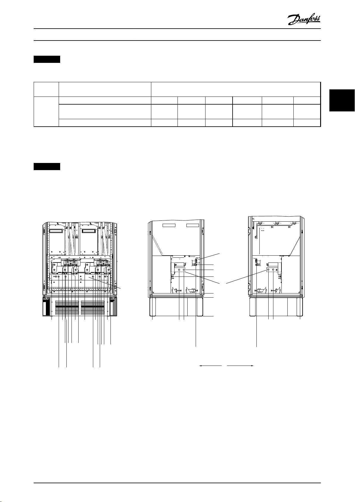
3.3.5 Terminal Locations - Enclosure type F
NOTICE
The F enclosures have 4 different sizes, F1, F2, F3 and F4. The F1 and F2 consist of an inverter cabinet on the right and
rectifier cabinet on the left. The F3 and F4 have an additional options cabinet left of the rectifier cabinet. The F3 is an
F1 with an additional options cabinet. The F4 is an F2 with an additional options cabinet.
Terminal locations - enclosure types F1 and F3
3 3
Illustration 3.29 Terminal Locations - Inverter Cabinet - F1 and F3 (Front, Left and Right Side View). The Gland Plate is 42 mm
below .0 Level.
1) Earth ground bar
2) Motor terminals
3) Brake terminals
MG20P402 - Rev. 2013-12-16 29

S1 F1
F1
DC ‘-’
DC ‘+’
1739.1
805.0
765.0
1694.1
1654.1
710.0
130BB377.10
287.4 [11.32]
0.0 [0.00]
339.4 [13.36]
253.1 [9.96]
0.0 [0.00]
287.4 [11.32]
0.0 [0.00]
339.4 [13.36]
465.6 [18.33]
465.6 [18.33]
308.3 [12.14]
180.3 [7.10]
210.1 [8.27]
0.0 [0.00]
66.4 [2.61]
181.4 [7.14]
296.4 [11.67]
431.0 [16.97]
546.0 [21.50]
661.0 [26.03]
795.7 [31.33]
910.7 [35.85]
1025.7 [40.38]
246.1 [9.69]
294.1 [11.58]
330.1 [13.00]
574.7 [22.63]
610.7 [24.04]
658.7 [25.93]
694.7 [27.35]
939.4 [36.98]
975.4 [38.40]
1023.4 [40.29]
1059.4 [41.71]
144.3 [5.68]
219.3 [8.63]
512.3 [20.17]
587.3 [23.12]
880.3 [34.66]
955.3 [37.61]
6
4
130BA850.12
FASTENER TORQUE: MIO 19 Nm (14 FT -LB)
U/T1 96 V/T2 97 W/T3 98
FASTENER TORQUE: MIO 19 Nm (14 FT -LB)
U/T1 96 V/T2 97 W/T3 98
FASTENER TORQUE: MIO 19 Nm (14 FT -LB)
U/T1 96 V/T2 97 W/T3 98
1
2
3
4
5
How to Install VLT AQUA Drive FC 202 Operation Instructions
33
Illustration 3.30 Terminal Locations - Regen Terminals - F1 and
F3
Terminal locations - enclosure types F2 and F4
Illustration 3.31 Terminal Locations - Inverter Cabinet - F2 and F4 (Front, Left and Right Side View). The Gland Plate is 42 mm
below .0 Level.
1) Earth Ground Bar
30 MG20P402 - Rev. 2013-12-16

S1 S2
S2
F1
F1
S2F1
DC ‘-’
DC ‘+’
1739.1
1203.2
1163.2
1694.1
1654.1
1098.1
130BB378.10
74.6 [2.9]
0.0 [0.0]
125.8 [4.95]
218.6 [8.61]
293.6 [11.56]
362.6 [14.28]
437.6 [17.23]
149.6 [5.89]
486.6 [19.16]
183.4 [7.22]
373.4 [14.70]
0.0 [0.00]
70.4 [2.77]
193.9 [7.64]
343.1 [13.51]
38.1 [1.50]
0.0 [0.00]
90.1 [3.55]
136.6 [5.38]
188.6 [7.42]
B
A
435.5 [17.15]
LOAD SHARE LOCATION
DIM F1/F2 F3/F4
A 380.5 [14.98] 29.4 [1.16]
B 432.5 [17.03] 81.4 [3.20]
6
5
4
130BA848.12
CH22 CH22
R/L1 91 S/L2 92
FASTENER TORQUE: M8 9.6 Nm (7 FT-LB)
T/L3 93
FASTENER TORQUE: M10 19 Nm (14 FT-LB)
FASTENER TORQUE: M10 19 Nm (14 FT-LB)
DC 89
FASTENER TORQUE: M10 19 Nm (14 FT-LB)
DC 89
CH22 CH22 CH22 CH22
CTI25MB CTI25MB
AUXAUXAUXAUXAUX
3
2
1
How to Install VLT AQUA Drive FC 202 Operation Instructions
Illustration 3.32 Terminal Locations - Regen Terminals - F2 and
F4
Terminal locations - Rectifier (F1, F2, F3 and F4)
3 3
Illustration 3.33 Terminal Locations - Rectifier (Left Side, Front and Right Side View). The Gland Plate is 42 mm below .0 Level.
1) Loadshare Terminal (-)
2) Earth Ground Bar
3) Loadshare Terminal (+)
MG20P402 - Rev. 2013-12-16 31

1 2 3
4
0.0[0.00]
76.4[3.01]
128.4[5.05]
119.0[4.69]
171.0[6.73]
294.6[11.60]
344.0[13.54]
3639[14.33]
438.9[17.28]
75.3[2.96]
150.3[5.92]
154.0[6.06]
219.6[18.65]
0.0[0.00]
244.4[9.62]
244.4[1.75]
939.0[36.97]
1031.4[40.61]
0.0[0.00]
134.6[5.30]
130BA851.12
0.0[1.75]
How to Install VLT AQUA Drive FC 202 Operation Instructions
Terminal locations - Options Cabinet (F3 and F4)
33
Illustration 3.34 Terminal Locations - Options Cabinet (Left Side, Front and Right Side View). The Gland Plate is 42 mm below .0
Level.
1) Earth Ground Bar
32 MG20P402 - Rev. 2013-12-16

0.0 [0.00]
134.6 [5.30]
104.3 [4.11]
0.0 [0.00]
179.3 [7.06]
219.6 [8.65]
294.6 [11.60]
334.8 [13.18]
409.8 [16.14]
436.9 [17.20]
0.0 [0.00]
532.9 [20.98]
0.0 [0.00]
44.4 [1.75]
244.4 [9.62]
154.0 [6.06]
344.0 [13.54]
1
234
5
130BA852.11
How to Install VLT AQUA Drive FC 202 Operation Instructions
Terminal locations - Options Cabinet with circuit breaker/ molded case switch (F3 and F4)
3 3
Illustration 3.35 Terminal Locations - Options Cabinet with Circuit Breaker/Molded Case Switch (Left Side, Front and Right Side View).
The Gland Plate is 42 mm below .0 Level.
1) Earth Ground Bar
Power size 2 3 4 5
500 kW (480
34.9 86.9 122.2 174.2
V), 710-800
kW (690 V)
560-1000 kW
46.3 98.3 119.0 171.0
(480 V),
900-1400 kW
(690 V)
Table 3.10 Dimensions for Terminal
3.3.6 Cooling and Airflow
Cooling
Cooling can be obtained in different ways, by using the
cooling ducts in the bottom and the top of the unit, by
taking air in and out the back of the unit or by combining
the cooling possibilities.
Duct cooling
A dedicated option has been developed to optimize installation of IP00/chassis frequency converters in Rittal TS8
enclosures utilizing the fan of the frequency converter for
forced air cooling of the backchannel. The air out of the
top of the enclosure could but ducted outside a facility so
the heat loses from the backchannel are not dissipated
within the control room reducing air-conditioning
requirements of the facility.
See chapter 3.4.1 Installation of Duct Cooling Kit in Rittal
Enclosures, for further information.
Back cooling
The backchannel air can also be ventilated in and out the
back of a Rittal TS8 enclosure. This offers a solution where
the backchannel could take air from outside the facility
and return the heat loses outside the facility thus reducing
air-conditioning requirements.
MG20P402 - Rev. 2013-12-16 33

90
80
70
60
50
40
30
20
10
0
0 0.5 4.9 13 27.3 45.9 66 89.3 115.7 147
(%)
(Pa)
Pressure Increase
Drive Derating
130BB007.10
90
80
70
60
50
40
30
20
10
0
(%)
Drive Derating
0 0 0.1 3.6 9.8 21.5 43.4 76 237.5 278.9
(Pa)
Pressure Change
130BB010.10
147.1
How to Install VLT AQUA Drive FC 202 Operation Instructions
CAUTION
A door fan(s) is required on the enclosure to remove the
heat losses not contained in the backchannel of the
frequency converter and any additional losses generated
from other components installed inside the enclosure.
33
The total required air flow must be calculated so that the
appropriate fans can be selected. Some enclosure
NOTICE
The fan runs for the following reasons:
1. AMA
2. DC Hold
3. Pre-Mag
4. DC Brake
manufacturers offer software for performing the
calculations (i.e. Rittal Therm software). If the frequency
converter is the only heat generating component in the
enclosure, the minimum airflow required at an ambient
temperature of 45 oC for the D3 and D4 frequency
converters is 391 m3/h (230 cfm). The minimum airflow
required at an ambient temperature of 45oC for the E2
frequency converter is 782 m3/h (460 cfm).
Airflow
The necessary airflow over the heat sink must be secured.
The flow rate is in Table 3.11.
Enclosure
protection Enclosure type
IP21/NEMA 1
D1 and D2
IP54/NEMA 12
E1 P315T5,
P450T7,
P500T7
E1 P355P450T5, P560P630T7
IP21/NEMA 1 F1, F2, F3 and
F4
IP54/NEMA 12 F1, F2, F3 and
F4
IP00/Chassis D3 and D4
E2 P315T5,
P450T7,
P500T7
E2 P355P450T5, P560P630T7
* Airflow per fan. enclosure type F contain multiple fans.
Door fan(s)/
Top fan
airflow
170 m3/h
(100 cfm)
340 m3/h
(200 cfm)
340 m3/h
(200 cfm)
700 m3/h
(412 cfm)*
525 m3/h
(309 cfm)*
255 m3/h
(150 cfm)
255 m3/h
(150 cfm)
255 m3/h
(150 cfm)
Heat sink
fan(s)
765 m3/h
(450 cfm)
1105 m3/h
(650 cfm)
1445 m3/h
(850 cfm)
985 m3/h
(580 cfm)*
985 m3/h
(580 cfm)*
765 m3/h
(450 cfm)
1105 m3/h
(650 cfm)
1445 m3/h
(850 cfm)
5. 60% of nominal current is exceeded
6. Specific heat sink temperature exceeded (power
size dependent)
7. Specific Power Card ambient temperature
exceeded (power size dependent)
8. Specific Control Card ambient temperature
exceeded
Once the fan is started it will run for minimum 10
minutes.
External ducts
If additional duct work is added externally to the Rittal
cabinet the pressure drop in the ducting must be
calculated. Use the charts below to derate the frequency
converter according to the pressure drop.
Illustration 3.36 D Enclosure Derating vs. Pressure Change
Frequency converter air flow: 450 cfm (765 m3/h)
Table 3.11 Heat Sink Air Flow
34 MG20P402 - Rev. 2013-12-16
Illustration 3.37 E Enclosure Derating vs. Pressure Change
(Small Fan), P315T5 and P450T7-P500T7
Frequency converter air flow: 650 cfm (1105 m3/h)

90
80
70
60
50
40
30
20
10
0
(%)
Drive Derating
0 0.2 0.6 2.2 5.8 11.4 18.1 30.8 152.8 210.8
(Pa)
Pressure Change
130BB011.10
69.5
90
80
70
60
50
40
30
20
10
0
(%)
Drive Derating
0 25 50 75 100 125 150 175 225
130BB190.10
200
Pressure Change
176FA245.10
130BB073.10
How to Install
VLT AQUA Drive FC 202 Operation Instructions
Illustration 3.38 E Enclosure Derating vs. Pressure Change
(Large Fan), P355T5-P450T5 and P560T7-P630T7
Frequency converter air flow: 850 cfm (1445 m3/h)
Illustration 3.40 Lifting Method for Mounting Frequency
Converter on Wall
Gland/Conduit Entry - IP21 (NEMA 1)
3.3.8
and IP54 (NEMA12)
Cables are connected through the gland plate from the
bottom. Remove the plate and plan where to place the
entry for the glands or conduits. Prepare holes in the
marked area on the drawing.
3 3
Illustration 3.39 F1, F2, F3, F4 Enclosures Derating vs. Pressure
Change
Frequency converter air flow: 580 cfm (985 m3/h)
Installation on the Wall - IP21 (NEMA
3.3.7
1) and IP54 (NEMA 12) Units
This only applies to enclosure types D1 and D2. It must be
considered where to install the unit.
Take the relevant points into consideration before
selecting the final installation site:
Free space for cooling
•
Access to open the door
•
Cable entry from the bottom
•
Mark the mounting holes carefully using the mounting
template on the wall and drill the holes as indicated.
Ensure proper distance to the floor and the ceiling for
cooling. A minimum of 225 mm (8.9 inch) below the
frequency converter is needed. Mount the bolts at the
bottom and lift the frequency converter up on the bolts.
Tilt the frequency converter against the wall and mount
the upper bolts. Tighten all 4 bolts to secure the frequency
converter against the wall.
NOTICE
The gland plate must be fitted to the frequency
converter to ensure the specified protection degree, as
well as ensuring proper cooling of the unit. If the gland
plate is not mounted, the frequency converter may trip
on Alarm 69, Pwr. Card Temp
Illustration 3.41 Example of Proper Installation of Gland Plate.
MG20P402 - Rev. 2013-12-16 35

2
1
176FA289.12
35
350
202.8
98.6
130.0
62.5
2
1
176FA289.12
35
350
202.8
98.6
130.0
62.5
1
130BA837.12
1328.8
(52.315)
595.8
(23.457)
533.0
(20.984)
36.2
(1.425)
281.8
(11.096)
535.0
(21.063)
216.5
(8.524)
37.7
(1.485)
460.0
(18.110)
668.3
(26.311)
593.0
(23.346)
199.5
(7.854)
258.5
(10.177)
35.5
(1.398)
533.0
[20.984]
594.8
[23.417] 1727.8
[68.024]
35.5
[1.398]
[21.063]
258.2
[10.167]
199.5
[7.854]
37.7
[1.485]
460.0
[18.110]
994.3
[39.146]
216.5
[8.524]
36.2
[1.425]
281.8
[11.096]
1
130BA841.12
535.0
655.9
25.825
1
130BA843.12
37.7
(1.485)
535.0
(21.063)
35.5
(1.398)
36.2
(1.425)
533.0
(20.984)
597.0
(23.504)
1130.0
(44.488)
1192.8
(46.961)
1925.8
(75.819)
258.5
(10.177)
199.5
(7.854)
2X 460.0
(18.110)
634.7
(24.989)
1265.3
(49.815)
593.0
(23.346)
2X 281.3
(11.075)
2X 216.5
(8.524)
How to Install VLT AQUA Drive FC 202 Operation Instructions
Cable entries viewed from the bottom of the frequency
converter - 1) Mains side 2) Motor side
Enclosure types F1-F4: Cable entries viewed from the
bottom of the frequency converter - 1) Place conduits in
marked areas
33
Illustration 3.44 Enclosure Type F1
Illustration 3.42 Enclosure Types D1 + D2
Illustration 3.43 Enclosure Type E1
36 MG20P402 - Rev. 2013-12-16
Illustration 3.45 Enclosure Type F2
Illustration 3.46 Enclosure Type F3

130BA839.10
1
37.7
(1.485)
533 (20.984)
597.0 (23.504)
1130.0 (44.488)
2324.8 (91.528)
535.0
(21.063)
2X 216.5
(8.524)
2X 460.0
(18.110)
634.7 (24.989)
35.5
(1.398)
258.2
(10.167)
199.5
(7.854)
1252.8
(49.321)
994.3
(39.146)
2X 281.8
(11.096)
36.2
(1.425)
1191.8 (46.921)
176FA285.10
176FA252.10
How to Install
Illustration 3.47 Enclosure Type F4
VLT AQUA Drive FC 202 Operation Instructions
3.3.9 IP21 Drip Shield Installation
(Enclosure Types D1 and D2)
To comply with the IP21 rating, a separate drip shield is
to be installed as explained below:
Remove the 2 front screws
•
Insert the drip shield and replace screws
•
Tighten the screws to 5.6 Nm (50 in-lbs)
•
3 3
Illustration 3.48 Drip Shield Installation.
3.4 Field Installation of Options
3.4.1 Installation of Duct Cooling Kit in
Rittal Enclosures
This section deals with the installation of IP00/chassis
enclosed frequency converters with duct work cooling kits
in Rittal enclosures. In addition to the enclosure a 200 mm
base/plinth is required.
Illustration 3.49 Installation of IP00 in Rittal TS8 Enclosure.
The minimum enclosure dimension is:
D3 and D4 enclosures: Depth 500 mm and width
•
600 mm.
E2 enclosure: Depth 600 mm and width 800 mm.
•
The maximum depth and width are as required by the
installation. When using multiple frequency converters in
one enclosure, it is recommended that each frequency
converter is mounted on its own back panel and
MG20P402 - Rev. 2013-12-16 37

176FT261.10
How to Install
VLT AQUA Drive FC 202 Operation Instructions
supported along the mid-section of the panel. These duct
work kits do not support the “in frame” mounting of the
panel (see Rittal TS8 catalogue for details). The duct work
cooling kits listed in Table 3.12 are suitable for use only
with IP00/Chassis frequency converters in Rittal TS8 IP 20
and UL and NEMA 1 and IP 54 and UL and NEMA 12
33
enclosures.
3.4.2
Outside Installation/NEMA 3R Kit for
Rittal Enclosures
CAUTION
For the E2 enclosures it is important to mount the plate
at the absolute rear of the Rittal enclosure due to the
weight of the frequency converter.
CAUTION
A doorfan(s) is required on the enclosure to remove the
heat losses not contained in the backchannel of the
frequency converter and any additional losses generated
from other components installed inside the enclosure.
The total required airflow must be calculated so that the
appropriate fans can be selected. Some enclosure
manufacturers offer software for performing the
calculations (i.e. Rittal Therm software). If the frequency
converter is the only heat generating component in the
enclosure, the minimum airflow required at an ambient
temperature of 45 °C for the D3 and D4 frequency
converters is 391 m3/h (230 cfm). The minimum airflow
required at an ambient temperature of 45 °C for the E2
frequency converter is 782 m3/h (460 cfm).
Illustration 3.50
Rittal TS-8
Enclosure
1800 mm 176F1824 176F1823 Not possible
2000 mm 176F1826 176F1825 176F1850
2200 mm 176F0299
Table 3.12 Ordering Information
Enclosure type
D3 Kit Part
No.
Enclosure type
D4 Kit Part No.
Enclosure
type E2 Part
No.
NOTICE
See the instruction Duct Work Cooling Kit Instruction for
Frames D3, D4 and E2 for further information.
External ducts
If additional duct work is added externally to the Rittal
cabinet the pressure drop in the ducting must be
calculated. See chapter 3.3.6 Cooling and Airflow for further
information.
This section is for the installation of NEMA 3R kits available
for the frequency converter enclosure types D3, D4 and E2.
These kits are designed and tested to be used with IP00/
Chassis versions of these enclosure types in Rittal TS8
NEMA 3R or NEMA 4 enclosures. The NEMA-3R enclosure is
an outdoor enclosure that provides a degree of protection
against rain and ice. The NEMA-4 enclosure is an outdoor
enclosure that provides a greater degree of protection
against weather and hosed water.
The minimum enclosure depth is 500 mm (600 mm for
enclosure type E2) and the kit is designed for a 600 mm
(800 mm for enclosure type E2) wide enclosure. Other
enclosure widths are possible, however additional Rittal
hardware is required. The maximum depth and width are
as required by the installation.
38 MG20P402 - Rev. 2013-12-16

175ZT976.10
How to Install VLT AQUA Drive FC 202 Operation Instructions
NOTICE
The current rating of frequency converters in enclosure
types D3 and D4 are de-rated by 3%, when adding the
NEMA 3R kit. Frequency converters in enclosure type E2
require no derating.
NOTICE
A doorfan(s) is required on the enclosure to remove the
heat losses not contained in the backchannel of the
frequency converter and any additional losses generated
from other components installed inside the enclosure.
The total required airflow must be calculated so that the
appropriate fans can be selected. Some enclosure
manufacturers offer software for performing the
calculations (i.e. Rittal Therm software). If the frequency
converter is the only heat generating component in the
enclosure, the minimum airflow required at an ambient
temperature of 45 °C for the D3 and D4 frequency
converters is 391 m3/h (230 cfm). The minimum airflow
required at an ambient temperature of 45 °C for the E2
frequency converter is 782 m3/h (460 cfm).
Ordering information
Enclosure type D3: 176F4600
Enclosure type D4: 176F4601
Enclosure type E2: 176F1852
NOTICE
See the instructions Installation of NEMA 3R Kit for IP00
Frames D3, D4 & E2 for further information.
3 3
3.4.3 Installation on Pedestal
This section describes the installation of a pedestal unit
available for the frequency converters enclosure types D1
and D2. This is a 200 mm high pedestal that allows these
enclosure types to be floor mounted. The front of the
pedestal has openings for input air to the power
components.
The frequency converter gland plate must be installed to
provide adequate cooling air to the control components of
the frequency converter via the door fan and to maintain
the IP21/NEMA 1 or IP54/NEMA 12 degrees of enclosure
protections.
Illustration 3.51 Frequency Converter on Pedestal
There is one pedestal that fits both enclosure types D1 and
D2. Its ordering number is 176F1827. The pedestal is
standard for enclosure type E1.
MG20P402 - Rev. 2013-12-16 39

176FA242.10
How to Install VLT AQUA Drive FC 202 Operation Instructions
NOTICE
See the Pedestal Kit Instruction Manual, for further
information.
3.4.4 Installation of Input Plate Options
33
This section is for the field installation of input option kits
available for frequency converters in all enclosure types D
and E.
Do not attempt to remove RFI filters from input plates.
Damage may occur to RFI filters if they are removed from
the input plate.
Illustration 3.52 Mounting of Frequency Converter to Pedestal
NOTICE
Where RFI filters are available, there are 2 different type of RFI filters depending on the input plate combination and
the RFI filters interchangeable. Field installable kits in certain cases are the same for all voltages.
D1 All D1 power sizes 176F8442 176F8450 176F8444 176F8448 176F8446
D2 All D2 power sizes 176F8443 176F8441 176F8445 176F8449 176F8447
E1 FC 102/ FC 202: 315 kW
Table 3.13 Fuses
D1 FC 102/ FC 202: 45-90
D2 All D2power sizes 175L8827 175L8826 175L8825 NA NA
E1 FC 102/ FC 202:
380-480 V
380-500 V
FC 302: 250 kW
FC 102/ FC 202: 355 450 kW
FC 302: 315 - 400 kW
525 - 690 V Fuses Disconnect Fuses RFI RFI Fuses RFI Disconnect
kW
FC 302: 37-75 kW
FC 102/ FC 202:
110-160 kW
FC 302: 90-132 kW
450-500 kW
FC 302: 355-400 kW
FC 102/ FC 202:
560-630 kW
FC 302: 500-560 kW
Fuses Disconnect Fuses RFI RFI Fuses RFI Disconnect
Fuses
176F0253 176F0255 176F0257 176F0258 176F0260
176F0254 176F0256 176F0257 176F0259 176F0262
Fuses
175L8829 175L8828 175L8777 NA NA
175L8442 175L8445 175L8777 NA NA
176F0253 176F0255 NA NA NA
176F0254 176F0258 NA NA NA
Table 3.14
40 MG20P402 - Rev. 2013-12-16

How to Install
VLT AQUA Drive FC 202 Operation Instructions
NOTICE
For further information, see the Instruction Installation of
Field Installable Kits for VLT Drives
3.4.5 Installation of Mains Shield for
Frequency Converters
This section is for the installation of a mains shield for the
frequency converter series with enclosure types D1, D2
and E1. It is not possible to install in the IP00/Chassis
versions as these have included as standard a metal cover.
These shields satisfy VBG-4 requirements.
Ordering numbers:
Enclosure types D1 and D2: 176F0799
Enclosure type E1: 176F1851
NOTICE
For further information, see the Instruction Sheet,
175R5923
3.5 Enclsoure Type F Panel Options
3.5.1 Enclsoure Type F Options
Space Heaters and Thermostat
Mounted on the cabinet interior of enclosure type F
frequency converters, space heaters controlled via
automatic thermostat help control humidity inside the
enclosure, extending the lifetime of frequency converter
components in damp environments. The thermostat
default settings turn on the heaters at 10 °C (50 °F) and
turn them off at 15.6 °C (60 °F).
Cabinet Light with Power Outlet
A light mounted on the cabinet interior of enclosure type
F frequency converters increase visibility during servicing
and maintenance. The housing the light includes a power
outlet for temporarily powering tools or other devices,
available in two voltages:
230 V, 50 Hz, 2.5 A, CE/ENEC
•
120 V, 60 Hz, 5 A, UL/cUL
•
Transformer Tap Setup
If the cabinet light & outlet and/or the space heaters &
thermostat are installed Transformer T1 requires it taps to
be set to the proper input voltage. A 380-480/500 V
frequency converter is set initially to the 525 V tap and a
525-690 V frequency converter is set to the 690 V tap to
insure no overvoltage of secondary equipment occurs if
the tap is not changed before power is applied. See
Table 3.15 to set the proper tap at terminal T1 located in
the rectifier cabinet. For location in the frequency
converter, see Illustration 3.53.
Input Voltage Range [V] Tap to Select
380-440 400 V
441-490 460 V
491-550 525 V
551-625 575 V
626-660 660 V
661-690 690 V
Table 3.15
NAMUR Terminals
NAMUR is an international association of automation
technology users in the process industries, primarily
chemical and pharmaceutical industries in Germany.
Selection of this option provides terminals organized and
labeled to the specifications of the NAMUR standard for
frequency converter input and output terminals. This
requires MCB 112 PTC Thermistor Card and MCB 113
Extended Relay Card.
RCD (Residual Current Device)
Uses the core balance method to monitor ground fault
currents in grounded and high-resistance grounded
systems (TN and TT systems in IEC terminology). There is a
pre-warning (50% of main alarm set-point) and a main
alarm set-point. Associated with each set-point is an SPDT
alarm relay for external use. Requires an external “windowtype” current transformer (supplied and installed by
customer).
Integrated into the frequency converter’s safe-
•
stop circuit
IEC 60755 Type B device monitors AC, pulsed DC,
•
and pure DC ground fault currents
LED bar graph indicator of the ground fault
•
current level from 10–100% of the set-point
Fault memory
•
[TEST/RESET]
•
Insulation Resistance Monitor (IRM)
Monitors the insulation resistance in ungrounded systems
(IT systems in IEC terminology) between the system phase
conductors and ground. There is an ohmic pre-warning
and a main alarm set-point for the insulation level.
Associated with each set-point is an SPDT alarm relay for
external use. Note: only one insulation resistance monitor
can be connected to each ungrounded (IT) system.
Integrated into the frequency converter’s safe-
•
stop circuit
LCD display of the ohmic value of the insulation
•
resistance
Fault Memory
•
[INFO], [TEST], and [RESET]
•
3 3
MG20P402 - Rev. 2013-12-16 41

3 Phase
power
input
130BA026.10
91 (L1)
92 (L2)
93 (L3)
95 PE
How to Install VLT AQUA Drive FC 202 Operation Instructions
33
IEC Emergency Stop with Pilz Safety Relay
Includes a redundant 4-wire emergency-stop push-button
mounted on the front of the enclosure and a Pilz relay that
monitors it in conjunction with the frequency converter’s
safe-stop circuit and the mains contactor located in the
options cabinet.
Safe Stop + Pilz Relay
Provides a solution for the "Emergency Stop" option
without the contactor in F-Enclosure frequency converters.
Manual Motor Starters
Provides 3-phase power for electric blowers often required
for larger motors. Power for the starters is provided from
the load side of any supplied contactor, circuit breaker, or
disconnect switch. Power is fused before each motor
starter, and is off when the incoming power to the
frequency converter is off. Up to 2 starters are allowed
(one if a 30 A, fuse-protected circuit is ordered). Integrated
into the frequency converter’s safe-stop circuit.
Unit features include:
Operation switch (on/off)
•
Short-circuit and overload protection with test
•
function
Manual reset function
•
30 A, Fuse-Protected Terminals
3-phase power matching incoming mains voltage
•
for powering auxiliary customer equipment
Not available if 2 manual motor starters are
•
selected
Terminals are off when the incoming power to
•
the frequency converter is off
Power for the fused protected terminals will be
•
provided from the load side of any supplied
contactor, circuit breaker, or disconnect switch.
24 V DC Power Supply
5 A, 120 W, 24 V DC
•
Protected against output over-current, overload,
•
short circuits, and over-temperature
For powering customer-supplied accessory
•
devices such as sensors, PLC I/O, contactors,
temperature probes, indicator lights, and/or other
electronic hardware
Diagnostics include a dry DC-ok contact, a green
•
DC-ok LED, and a red overload LED
External Temperature Monitoring
Designed for monitoring temperatures of external system
components, such as the motor windings and/or bearings.
Includes five universal input modules. The modules are
integrated into the frequency converter’s safe-stop circuit
and can be monitored via a fieldbus network (requires the
purchase of a separate module/bus coupler).
42 MG20P402 - Rev. 2013-12-16
Universal inputs (5)
Signal types:
•
•
•
Additional features:
•
•
•
•
•
3.6 Electrical Installation
3.6.1 Power Connections
Cabling and Fusing
NOTICE
Cables General
All cabling must comply with national and local
regulations on cable cross-sections and ambient
temperature. UL applications require 75 °C copper
conductors. 75 and 90 °C copper conductors are
thermally acceptable for the frequency converter to use
in non UL applications.
The power cable connections are situated as shown below.
Dimensioning of cable cross section must be done in
accordance with the current ratings and local legislation.
See the Specifications section for details.
For protection of the frequency converter, the
recommended fuses must be used or the unit must be
with built-in fuses. Recommended fuses can be seen in the
tables of the fuse section. Always ensure that proper fusing
is made according to local regulation.
The mains connection is fitted to the mains switch if this is
included.
Illustration 3.53 Power Cable Connections
RTD inputs (including PT100), 3-wire or 4-wire
Thermocouple
Analog current or analog voltage
One universal output, configurable for analog
voltage or analog current
Two output relays (N.O.)
Dual-line LC display and LED diagnostics
Sensor lead wire break, short-circuit, and incorrect
polarity detection
Interface setup software

U
1
V
1
W
1
175ZA114.11
96 97 98
96 97 98
FC
FC
Motor
Motor
U
2
V
2
W
2
U
1
V
1
W
1
U
2
V
2
W
2
How to Install VLT AQUA Drive FC 202 Operation Instructions
NOTICE
The motor cable must be screened/armoured. If an
unscreened/unarmoured cable is used, some EMC
requirements are not complied with. Use a screened/
armoured motor cable to comply with EMC emission
specifications. For more information, see EMC specifi-
cations in the Design Guide.
See section General Specifications for correct dimensioning
of motor cable cross-section and length.
3 3
Screening of cables
Avoid installation with twisted screen ends (pigtails). They
spoil the screening effect at higher frequencies. If it is
necessary to break the screen to install a motor isolator or
motor contactor, the screen must be continued at the
lowest possible HF impedance.
Connect the motor cable screen to both the de-coupling
plate of the frequency converter and to the metal housing
of the motor.
Make the screen connections with the largest possible
surface area (cable clamp). This is done by using the
supplied installation devices within the frequency
converter.
Cable-length and cross-section
The frequency converter has been EMC tested with a given
length of cable. Keep the motor cable as short as possible
to reduce the noise level and leakage currents.
Switching frequency
When frequency converters are used together with Sinewave filters to reduce the acoustic noise from a motor, the
switching frequency must be set according to the
instruction in 14-01 Switching Frequency.
Illustration 3.54 Star/Delta Connections
Term
. no.
1)
Protected Earth Connection
NOTICE
In motors without phase insulation paper or other
insulation reinforcement suitable for operation with
voltage supply (such as a frequency converter), fit a Sinewave filter on the output of the frequency converter.
96 97 98 99
U V W
1)
Motor voltage 0-100% of mains
PE
voltage.
3 wires out of motor
U1 V1 W1
W2 U2 V2 6 wires out of motor
U1 V1 W1
Delta-connected
1)
PE
1)
Star-connected U2, V2, W2
PE
U2, V2 and W2 to be interconnected
separately.
Table 3.16
MG20P402 - Rev. 2013-12-16 43

DOWN
DOWN DOWN
DOWN
R/L1 91
S/L2 92
FASTENER TORQUE: M10 19 NM (14 FT-LB
T/L3 93
FASTENER TORQUE: M8 9.6 NM (7 FT-LB)
FASTENER TORQUE: M8 9.6 NM (7 FT-LB)
FASTENER TORQUE: M1019 NM (14 FT-LB)
-DC 88
+DC 89
-R 81
+R 82
U/T1 96
V/T2 97
W/T3 98
130BB015.10
1
2
3
4
6
7
8
9
10
5
130BB016.10
R/L1 91
S/L2 92
T/L3 93
FASTENER
TORQUE.
M10 19 NM (14 FT-LB)
1
2
3
4
5
6
7
8
9
10
FASTENER TORQUE:
FASTENER TORQUE: M10 19 NM (7 FT-LB)
FASTENER TORQUE:
-DV 88
-R 81
+R 82
U/T1 96
V/T2 97
W/T3 98
+DC 89
M8 9.6 NM (7 FT-LB)
M8 9.6 NM (7 FT-LB)
How to Install VLT AQUA Drive FC 202 Operation Instructions
33
Illustration 3.55 Compact IP21 (NEMA 1) and IP54 (NEMA 12),
Enclosure Type D1
AUX Relay 5) Brake
1)
01 02 03 -R +R
04 05 06 81 82
2) Temp Switch 6) SMPS Fuse (see fuse tables for part number)
106 104 105 7) AUX Fan
3) Mains 100 101 102 103
Illustration 3.56 Compact IP21 (NEMA 1) and IP54 (NEMA 12)
with Disconnect, Fuse and RFI Filter, Enclosure Type D2
R S T L1 L2 L1 L2
91 92 93 8) Fan Fuse (see fuse tables for part number)
L1 L2 L3 9) Mains ground
4) Load sharing 10) Motor
-DC +DC U V W
88 89 96 97 98
T1 T2 T3
Table 3.17 Legend to Illustration 3.55 and Illustration 3.56
44 MG20P402 - Rev. 2013-12-16

130BB017.10
1
2
3
4
5
6
7
8
9
10
1
2
3
4
5
6
7
8
9
10
130BB018.10
FASTEMER TORQUE: M10 19 NM (14 FT-LB)
FASTEMER TORQUE: M8 9.6 NM (7 FT-LB)
R/L1 91
-DC 88
+DC 89
FASTEMER TORQUE: M8 9.6 NM (7 FT-LB)
FASTEMER TORQUE: M10 19 NM (14 FT-LB)
R 81
+DR 82
U/T1 96
V/T2 97
W/T3 98
S/L2 92
T/L3 93
How to Install VLT AQUA Drive FC 202 Operation Instructions
3 3
Illustration 3.57 Compact IP00 (Chassis), Enclosure Type D3
Illustration 3.58 Compact IP00 (Chassis) with Disconnect, Fuse
and RFI Filter, Enclosure Type D4
AUX Relay 4) Load sharing 8) Fan Fuse (see fuse tables for
1)
part number)
01 02 03 -DC +DC 9) Mains ground
04 05 06 88 89 10) Motor
2) Temp Switch 5) Brake U V W
106 104 105 -R +R 96 97 98
3) Mains 81 82 T1 T2 T3
R S T 6) SMPS Fuse (see fuse tables for part number)
91 92 93 7) AUX Fan
L1 L2 L3 100 101 102 103
L1 L2 L1 L2
Table 3.18 Legend to Illustration 3.57 and Illustration 3.58
MG20P402 - Rev. 2013-12-16 45

TERMINALS
EARTH
130BA450.10
130BA455.10
M10 19 NM (14 FT -LB)
T2 97
W/T3 98
EARTH
TERMINALS
How to Install VLT AQUA Drive FC 202 Operation Instructions
33
Illustration 3.59 Position of Earth Terminals IP00, Enclosure
Type D
Illustration 3.60 Position of Earth Terminals IP21 (NEMA type
1) and IP54 (NEMA type 12)
NOTICE
D2 and D4 shown as examples. D1 and D3 are
equivalent.
46 MG20P402 - Rev. 2013-12-16

130BB019.10
1
2
3
4
5
6
7
8
9
10
130BB020.10
1
2
3
4
5
6
7
8
10
How to Install VLT AQUA Drive FC 202 Operation Instructions
3 3
Illustration 3.61 Compact IP21 (NEMA 1) and IP54 (NEMA 12)
Enclosure Type E1
Illustration 3.62 Compact IP00 (Chassis) with Disconnect, Fuse
and RFI Filter, Enclosure Type E2
AUX Relay 5) Load sharing
1)
01 02 03 -DC +DC
04 05 06 88 89
2) Temp Switch 6) SMPS Fuse (see fuse tables for part number)
106 104 105 7) Fan Fuse (see fuse tables for part number)
3) Mains 8) AUX Fan
R S T 100 101 102 103
91 92 93 L1 L2 L1 L2
L1 L2 L3 9) Mains ground
4) Brake 10) Motor
-R +R U V W
81 82 96 97 98
T1 T2 T3
Table 3.19 Legend to Illustration 3.61 and Illustration 3.62
MG20P402 - Rev. 2013-12-16 47

176FA259.10
Earth Terminals
:ASTENER TORQUE: MM8 9.6 Nm (7FT-LB)
ASTENER TORQUE: M10 19 Nm (14FT-LB)
S/L2 92
T/L3 93
R/L1 91
W/T3 98
How to Install VLT AQUA Drive FC 202 Operation Instructions
33
Illustration 3.63 Position of Earth Terminals IP00, Enclosure Type E
48 MG20P402 - Rev. 2013-12-16

+DC 89
FASTENER TORQUE: M10 19Nm (14 FT -LB)
+DC 89
130BA860.10
1
5
4
3
2
8
10
9
FUSE
C J3
ONNECT
CH22 CH22 CH22
CTI25MB
FASTENER TORQUE: M10 19Nm (14 FT -LB)
CTI25MB
CH22 CH22 CH22
7
6
How to Install
VLT AQUA Drive FC 202 Operation Instructions
3 3
1) 24 V DC, 5 A 5) Loadsharing
T1 Output Taps -DC +DC
Temp Switch 88 89
106 104 105 6) Control Transformer Fuses (2 or 4 pieces). See fuse tables for part numbers
2) Manual Motor Starters 7) SMPS Fuse. See fuse tables for part numbers
3) 30 A Fuse Protected Power Terminals 8) Manual Motor Controller fuses (3 or 6 pieces). See fuse tables for part numbers
4) Mains 9) Line Fuses, enclosure types F1 and F2 (3 pieces). See fuse tables for part
numbers
R S T 10) 30 Amp Fuse Protected Power fuses
L1 L2 L3
Illustration 3.64 Rectifier Cabinet, Enclosure Types F1, F2, F3 and F4
MG20P402 - Rev. 2013-12-16 49

2
5
6
4, 8, 9
130BA861.11
1
How to Install
VLT AQUA Drive FC 202 Operation Instructions
33
1) External Temperature Monitoring 6) Motor
2) AUX Relay U V W
01 02 03 96 97 98
04 05 06 T1 T2 T3
3) NAMUR 7) NAMUR Fuse. See fuse tables for part numbers
4) AUX Fan 8) Fan Fuses. See fuse tables for part numbers
100 101 102 103 9) SMPS Fuses. See fuse tables for part numbers
L1 L2 L1 L2
5) Brake
-R +R
81 82
Illustration 3.65 Inverter Cabinet, Enclosure Types F1 and F3
50 MG20P402 - Rev. 2013-12-16

3
5
U/T1 96
FASTENER TORQUE: M10 19 Nm (14 FT-LB)
V/T2 97 W/T3 98 U/T1 96
FASTENER TORQUE: M10 19 Nm (14 FT-LB)
V/T2 97 W/T3 98 U/T1 96
FASTENER TORQUE: M10 19 Nm (14 FT-LB)
V/T2 97 W/T3 98
6
4, 8, 9
2
1
7
130BA862.12
How to Install
VLT AQUA Drive FC 202 Operation Instructions
3 3
1) External Temperature Monitoring 6) Motor
2) AUX Relay U V W
01 02 03 96 97 98
04 05 06 T1 T2 T3
3) NAMUR 7) NAMUR Fuse. See fuse tables for part numbers
4) AUX Fan 8) Fan Fuses. See fuse tables for part numbers
100 101 102 103 9) SMPS Fuses. See fuse tables for part numbers
L1 L2 L1 L2
5) Brake
-R +R
81 82
Illustration 3.66 Inverter Cabinet, Enclosure Types F2 and F4
MG20P402 - Rev. 2013-12-16 51

2
3
4
5
6
7
1
130BA853.12
How to Install
VLT AQUA Drive FC 202 Operation Instructions
33
1) Pilz Relay Terminal 4) Safety Relay Coil Fuse with PILZ Relay
2) RCD or IRM Terminal See fuse tables for part numbers
3) Mains 5) Line Fuses, F3 and F4 (3 pieces)
R S T See fuse tables for part numbers
91 92 93 6) Contactor Relay Coil (230 VAC). N/C and N/O Aux Contacts
(customer supplied)
L1 L2 L3 7) Circuit Breaker Shunt Trip Control Terminals (230 V AC or 230 V
DC)
Illustration 3.67 Options Cabinet, Enclosure Types F3 and F4
52 MG20P402 - Rev. 2013-12-16

176FA247.12
Nm/in-lbs
-DC 88
+DC 89
R/L1 91
S/L2 92
T/L3 93
U/T1 96
V/T2 97
W/T3
How to Install VLT AQUA Drive FC 202 Operation Instructions
3.6.2 Grounding
The following basic issues need to be considered when
installing a frequency converter, so as to obtain electromagnetic compatibility (EMC).
Safety grounding: The frequency converter has a
•
high leakage current and must be grounded
appropriately for safety reasons. Apply local
safety regulations.
High-frequency grounding: Keep the ground wire
•
connections as short as possible.
Connect the different ground systems at the lowest
possible conductor impedance. The lowest possible
conductor impedance is obtained by keeping the
conductor as short as possible and by using the greatest
possible surface area.
The metal cabinets of the different devices are mounted
on the cabinet rear plate using the lowest possible HF
impedance. This avoids having different HF voltages for
the individual devices and avoids the risk of radio
interference currents running in connection cables that
may be used between the devices. The radio interference
has been reduced.
To obtain a low HF impedance, use the fastening bolts of
the devices as HF connection to the rear plate. It is
necessary to remove insulating paint or similar from the
fastening points.
In OFF, the internal RFI capacities (filter capacitors)
between the chassis and the intermediate circuit are cut
off to avoid damage to the intermediate circuit and to
reduce the earth capacity currents (according to IEC
61800-3).
Also refer to the application note VLT on IT Mains It is
important to use isolation monitors that are capable for
use together with power electronics (IEC 61557-8).
3.6.5 Torque
When tightening all electrical connections it is very
important to tighten with the correct torque. Too low or
too high torque results in a bad electrical connection. Use
a torque wrench to ensure correct torque.
3 3
Extra Protection (RCD)
3.6.3
ELCB relays, multiple protective earthing or earthing can
be used as extra protection, provided that local safety
regulations are complied with.
In case of an ground fault, a DC component may develop
in the fault current.
If ELCB relays are used, local regulations must be observed.
Relays must be suitable for protection of 3-phase
equipment with a bridge rectifier and for a brief discharge
on power-up.
See also Special Conditions in the Design Guide.
3.6.4
RFI Switch
Mains supply isolated from earth
If the frequency converter is supplied from an isolated
mains source ( IT mains, floating delta and grounded delta)
or TT/TN-S mains with grounded leg, the RFI switch is
recommended to be turned off (OFF) via 14-50 RFI Filter on
the frequency converter and 14-50 RFI Filter on the filter.
For further reference, see IEC 364-3. In case optimum EMC
performance is needed, parallel motors are connected or
the motor cable length is above 25 m, it is recommended
to set 14-50 RFI Filter to [ON].
Illustration 3.68 Tightening Bolts with a Torque Wrench
Enclosure
Terminal Torque [Nm] (in-lbs) Bolt size
types
D Mains
Motor
Load sharing
Brake
E Mains
Motor
Load sharing
Brake
19-40
(168-354)
8.5-20.5
(75-181)
19-40
(168-354)
8.5-20.5
(75-181)
M10
M8
M10
M8
MG20P402 - Rev. 2013-12-16 53

175HA036.11
U1V
1
W
1
96 97 98
FC
Motor
U
2V2
W
2
U1V
1
W
1
96 97 98
FC
Motor
U
2V2
W
2
How to Install VLT AQUA Drive FC 202 Operation Instructions
Enclosure
Terminal Torque [Nm] (in-lbs) Bolt size
types
F Mains
Motor
Load sharing
Brake
33
Regen
19-40
(168-354)
19-40
(168-354)
8.5-20.5
(75-181)
8.5-20.5
M10
M10
M8
M8
Terminal U/T1/96 connected
•
to U-phase
Terminal V/T2/97 connected
•
to V-phase
Terminal W/T3/98
•
connected to W-phase
(75-181)
Table 3.20 Torque for Terminals
Shielded Cables
3.6.6
Table 3.22
WARNING
Danfoss recommends to use shielded cables between the
The direction of rotation can be changed by switching 2 phases in
the motor cable or by changing the setting of 4-10 Motor Speed
Direction.
LCL filter and the AFE unit. Unshielded cables can be
between transformer and LCL filter input side.
Motor rotation check can be performed using 1-28 Motor
Rotation Check and following the steps shown in the
It is important that shielded and armoured cables are
display.
connected in a proper way to ensure the high EMC
immunity and low emissions.
F enclosure requirements
F1/F3 requirements: Motor phase cable quantities must be
The connection can be made using either cable glands
or clamps
EMC cable glands: Generally available cable
•
glands can be used to ensure an optimum EMC
connection.
EMC cable clamp: Clamps allowing easy
•
connection are supplied with the frequency
converter.
multiples of 2, resulting in 2, 4, 6, or 8 (1 cable is not
allowed) to obtain equal amount of wires attached to both
inverter module terminals. The cables are required to be
equal length within 10% between the inverter module
terminals and the first common point of a phase. The
recommended common point is the motor terminals.
F2/F4 requirements: Motor phase cable quantities must be
multiples of 3, resulting in 3, 6, 9, or 12 (1 or 2 cables are
not allowed) to obtain equal amount of wires attached to
Motor Cable
3.6.7
The motor must be connected to terminals U/T1/96, V/
T2/97, W/T3/98. Earth to terminal 99. All types of 3-phase
asynchronous standard motors can be used with a
frequency converter unit. The factory setting is for
clockwise rotation with the frequency converter output
connected as follows:
each inverter module terminal. The wires are required to
be equal length within 10% between the inverter module
terminals and the first common point of a phase. The
recommended common point is the motor terminals.
Output junction box requirements: The length, minimum
2.5 m, and quantity of cables must be equal from each
inverter module to the common terminal in the junction
box.
NOTICE
Terminal No. Function
96, 97, 98, 99 Mains U/T1, V/T2, W/T3
Earth
Table 3.21 Mains Terminals
If a retrofit application requires unequal amount of wires
per phase, consult the factory for requirements and
documentation or use the top/bottom entry side cabinet
option.
54 MG20P402 - Rev. 2013-12-16

How to Install VLT AQUA Drive FC 202 Operation Instructions
3.6.8 Brake Cable for Frequency Converters
with Factory Installed Brake Chopper
Option
(Only standard with letter B in position 18 of typecode).
The connection cable to the brake resistor must be
screened and the max. length from frequency converter to
the DC bar is limited to 25 m (82 ft).
Terminal No. Function
81, 82 Brake resistor terminals
Table 3.23 Terminals for Brake Resistor
The connection cable to the brake resistor must be
screened. Connect the screen with cable clamps to the
conductive back plate at the frequency converter and to
the metal cabinet of the brake resistor.
Size the brake cable cross-section to match the brake
torque. See also the instructions Brake Resistor and Brake
Resistors for Horizontal Applications for further information
regarding safe installation.
NOTICE
If the temperature of the brake resistor gets too high
and the thermal switch drops out, the frequency
converter stops braking. The motor starts coasting.
3.6.10 Load Sharing
Terminal No. Function
88, 89 Loadsharing
Table 3.25 Terminals for Load Sharing
The connection cable must be screened and the max.
length from the frequency converter to the DC bar is
limited to 25 m (82 ft).
Load sharing enables linking of the DC intermediate
circuits of several frequency converters.
WARNING
Voltages up to 1099 V DC may occur on the terminals.
Load Sharing calls for extra equipment and safety
considerations. For further information, see the
instuctions Load Sharing.
3 3
WARNING
Note that voltages up to 1099 V DC, depending on the
supply voltage, may occur on the terminals.
F enclosure requirements
The brake resistor(s) must be connected to the brake
terminals in each inverter module.
Brake Resistor Temperature Switch
3.6.9
Torque: 0.5-0.6 Nm (5 in-lbs)
Screw size: M3
This input can be used to monitor the temperature of an
externally connected brake resistor. If the input between
104 and 106 is established, the frequency converter trips
on warning/alarm 27, Brake IGBT. If the connection is
closed between 104 and 105, the frequency converter trips
on warning/alarm 27, Brake IGBT.
Install a KLIXON switch that is normally closed. If this
function is not used, short circuit 106 and 104 together.
Normally closed: 104-106 (factory installed jumper)
Normally open: 104-105
WARNING
Mains disconnect may not isolate the frequency
converter due to DC-link connection.
3.6.11 Shielding against Electrical Noise
Before mounting the mains power cable, mount the EMC
metal cover to ensure best EMC performance.
NOTICE
The EMC metal cover is only included in units with an
RFI filter.
Terminal No. Function
106, 104, 105 Brake resistor temperature switch.
Table 3.24 Terminals for Brake Resister Temperature Switch
MG20P402 - Rev. 2013-12-16 55
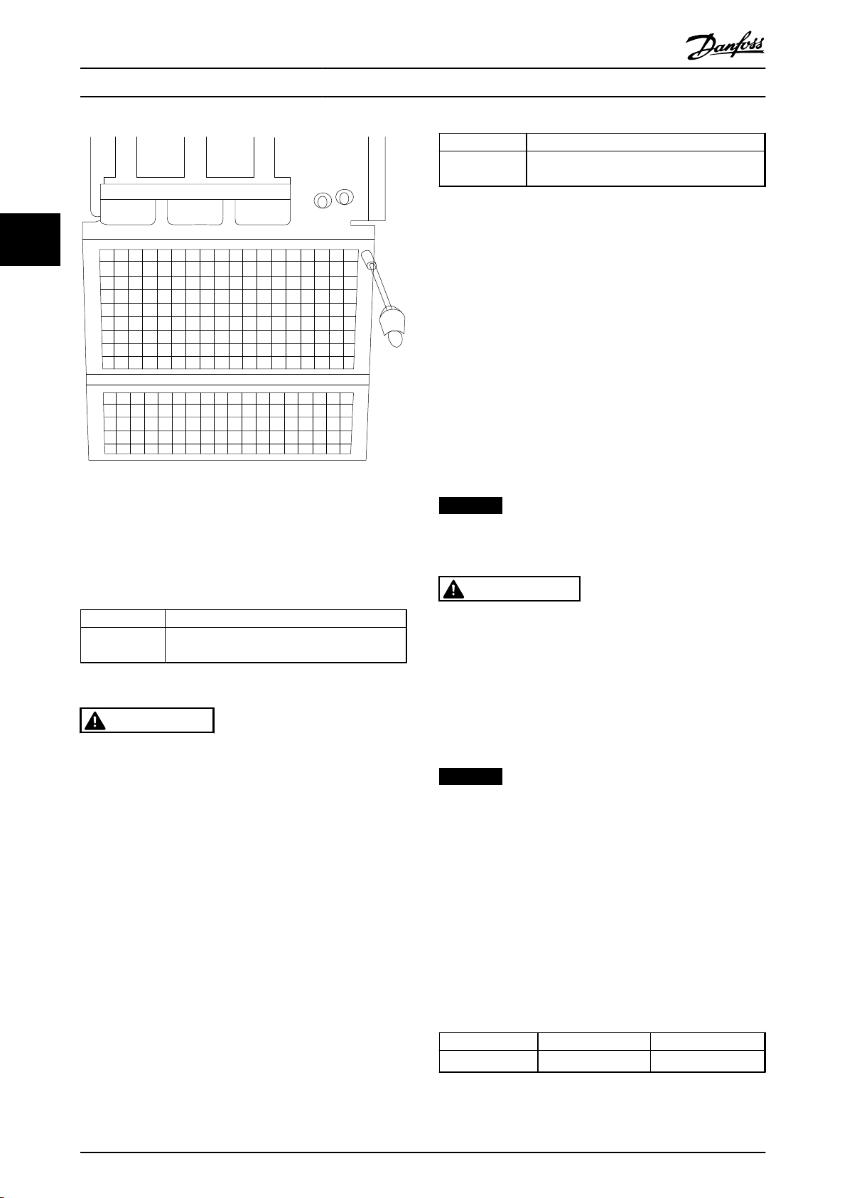
175ZT975.10
How to Install
VLT AQUA Drive FC 202 Operation Instructions
Terminal No. Function
100, 101
102, 103
Table 3.27 External Fan Supply Terminals
Auxiliary supply S, T
Internal supply S, T
33
Illustration 3.69 Mounting of EMC Shield.
The connector located on the power card provides the
connection of line voltage for the cooling fans. The fans
are connected from factory to be supplied from a common
AC line (jumpers between 100-102 and 101-103). If external
supply is needed, the jumpers are removed and the supply
is connected to terminals 100 and 101. Use a 5 A fuse for
protection. In UL applications, use a LittelFuse KLK-5 or
equivalent.
3.6.14
It is recommended to use fuses and/or circuit breakers on
the supply side as protection in case of component breakdown inside the frequency converter (first fault).
Fuses
NOTICE
3.6.12
Mains must be connected to terminals 91, 92 and 93. Earth
is connected to the terminal to the right of terminal 93.
Mains Connection
This is mandatory to ensure compliance with IEC 60364
for CE or NEC 2009 for UL.
WARNING
Terminal No. Function
91, 92, 93
94
Mains R/L1, S/L2, T/L3
Earth
Personnel and property must be protected against the
consequence of component break-down internally in the
frequency converter.
Table 3.26 Mains Terminals Connection
CAUTION
Check the name plate to ensure that the mains voltage
of the frequency converter matches the power supply of
the plant.
Ensure that the power supply can supply the necessary
current to the frequency converter.
If the unit is without built-in fuses, ensure that the
appropriate fuses have the correct current rating.
3.6.13
In case the frequency converter is supplied by DC or if the
fan must run independently of the power supply, an
external power supply can be applied. The connection is
made on the power card.
External Fan Supply
Branch circuit protection
To protect the installation against electrical and fire hazard,
all branch circuits in an installation, switch gear, machines
etc., must be protected against short-circuit and
overcurrent according to national/international regulations.
NOTICE
The recommendations given do not cover branch circuit
protection for UL.
Short-circuit protection:
Danfoss recommends using the fuses/circuit breakers
mentioned below to protect service personnel and
property in case of component break-down in the
frequency converter.
Non UL compliance
If UL/cUL is not to be complied with, use the following
fuses to ensure compliance with EN50178:
P110 - P250
P315 - P450 380 - 480 V type gR
Table 3.28
380 - 480 V type gG
56 MG20P402 - Rev. 2013-12-16

How to Install VLT AQUA Drive FC 202 Operation Instructions
UL Compliance
380-480 V, Enclosure types D, E and F
The fuses below are suitable for use on a circuit capable of delivering 100,000 A
(symmetrical), 240 V, or 480 V, or 500 V,
rms
or 600 V depending on the frequency converter voltage rating. With the proper fusing, the frequency converter Short Circuit
Current Rating (SCCR) is 100,000 A
rms
.
Size/
Type
P110 FWH-
P132 FWH-
P160 FWH-
P200 FWH-
P250 FWH-
Table 3.29 Enclosure Types D, Line Fuses, 380-480 V
Size/
Type
P315 170M4017 700 A,
P355 170M6013 900 A,
P400 170M6013 900 A,
P450 170M6013 900 A,
Table 3.30 Enclosure Types E, Line Fuses, 380-480 V
Size/
Type
P500 170M7081 1600 A,
P560 170M7081 1600 A,
P630 170M7082 2000 A,
P710 170M7082 2000 A,
P800 170M7083 2500 A,
P1M0 170M7083 2500 A,
Bussmann
E1958
JFHR2**
300
350
400
500
600
Bussmann
PN*
Bussmann
PN*
Bussmann
E4273
T/JDDZ**
JJS300
JJS350
JJS400
JJS500
JJS600
Rating Ferraz Siba
6.9URD31D08A070020 610 32.700
700 V
6.9URD33D08A090020 630 32.900
700 V
6.9URD33D08A090020 630 32.900
700 V
6.9URD33D08A090020 630 32.900
700 V
Rating Siba
700 V
700 V
700 V
700 V
700 V
700 V
SIBA
E180276
JFHR2
2061032.315 L50S-300 A50-P300 NOS-
2061032.35 L50S-350 A50-P350 NOS-
2061032.40 L50S-400 A50-P400 NOS-
2061032.50 L50S-500 A50-P500 NOS-
2062032.63 L50S-600 A50-P600 NOS-
20 695 32.1600 170M7082
20 695 32.1600 170M7082
20 695 32.2000 170M7082
20 695 32.2000 170M7082
20 695 32.2500 170M7083
20 695 32.2500 170M7083
LittelFuse
E71611
JFHR2**
Internal
Bussmann
Option
Ferraz-
Shawmut
E60314
JFHR2**
Size/Type
P500 170M8611 1100 A,
P560 170M8611 1100 A,
P630 170M6467 1400 A,
P710 170M6467 1400 A,
P800 170M8611 1100 A,
P1M0 170M6467 1400 A,
Table 3.32 Enclosure Type F, Inverter Module DC Link Fuses,
380-480 V
*170M fuses from Bussmann shown use the -/80 visual indicator, TN/80 Type T, -/110 or TN/110 Type T indicator fuses of the same size
and amperage may be substituted for external use
**Any minimum 500 V UL listed fuse with associated current rating
may be used to meet UL requirements.
Bussmann
E4274
H/JDDZ**
Bussmann
PN*
Bussmann
E125085
JFHR2*
170M3017 170M3018
300
170M3018 170M3018
350
170M4012 170M4016
400
170M4014 170M4016
500
170M4016 170M4016
600
Rating Siba
1000 V
1000 V
700 V
700 V
1000 V
700 V
Internal
Option
Bussmann
20 781 32.1000
20 781 32.1000
20 681 32.1400
20 681 32.1400
20 781 32.1000
20 681 32.1400
3 3
Table 3.31 Enclosure Types F, Line Fuses, 380-480 V
MG20P402 - Rev. 2013-12-16 57

How to Install
VLT AQUA Drive FC 202 Operation Instructions
525-690 V, Enclosure Types D, E and F
Buss-
mann
Size/
E1250
Type
33
P45K 170M
P55K 170M
P75K 170M
P90K 170M
P110 170M
P132 170M
P160 170M
P200 170M
P250 170M
P315 170M
P400 170M
Size/
Type
P450 170M4017 700 A,
P500 170M4017 700 A,
P560 170M6013 900 A,
P630 170M6013 900 A,
85
JFHR2
3013
3014
3015
3015
3016
3017
3018
4011
4012
4014
5011
Table 3.33 Enclosure Types D, E and F 525-690 V
Bussmann
PN*
SIBA
E1802
[A]
125 20610
160 20610
200 20610
200 20610
250 20610
315 20610
350 20610
350 20610
400 20610
500 20610
550 20620
76
JFHR2
32.125
32.16
32.2
32.2
32.25
32.315
32.35
32.35
32.4
32.5
32.55
Rating Ferraz Siba
700 V
700 V
700 V
700 V
Ferraz-
Shawmut
E76491
JFHR2
6.6URD30D08
A0125
6.6URD30D08
A0160
6.6URD30D08
A0200
6.6URD30D08
A0200
6.6URD30D08
A0250
6.6URD30D08
A0315
6.6URD30D08
A0350
6.6URD30D08
A0350
6.6URD30D08
A0400
6.6URD30D08
A0500
6.6URD32D08
A550
6.9URD31
D08A070
0
6.9URD31
D08A070
0
6.9URD33
D08A090
0
6.9URD33
D08A090
0
Internal
Option
Bussmann
170M3015
170M3015
170M3015
170M3015
170M3018
170M3018
170M3018
170M5011
170M5011
170M5011
170M5011
20 610 32.700
20 610 32.700
20 630 32.900
20 630 32.900
Size/
Type
P710 170M7081 1600 A,
P800 170M7081 1600 A,
P900 170M7081 1600 A,
P1M0 170M7081 1600 A,
P1M2 170M7082 2000 A,
P1M4 170M7083 2500 A,
Table 3.35 Enclosure Type Size F, Line Fuses, 525-690 V
Size/Type
P710 170M8611 1100 A,
P800 170M8611 1100 A,
P900 170M8611 1100 A,
P1M0 170M8611 1100 A,
P1M2 170M8611 1100 A,
P1M4 170M8611 1100 A,
Table 3.36 Enclosure Type F, Inverter Module DC Link Fuses,
525-690 V
*170M fuses from Bussmann shown use the -/80 visual indicator, TN/80 Type T, -/110 or TN/110 Type T indicator fuses of the same size
and amperage may be substituted for external use.
Bussmann
PN*
Bussmann
PN*
Rating Siba
20 695 32.1600 170M7082
700 V
20 695 32.1600 170M7082
700 V
20 695 32.1600 170M7082
700 V
20 695 32.1600 170M7082
700 V
20 695 32.2000 170M7082
700 V
20 695 32.2500 170M7083
700 V
Rating Siba
20 781 32. 1000
1000 V
20 781 32. 1000
1000 V
20 781 32. 1000
1000 V
20 781 32. 1000
1000 V
20 781 32. 1000
1000 V
20 781 32.1000
1000 V
Suitable for use on a circuit capable of delivering not more
than 100 000 rms symmetrical A, 500/600/690 V maximum
when protected by the above fuses.
Supplementary fuses
Enclosure Type
D, E and F KTK-4 4 A, 600 V
Bussmann PN* Rating
Internal
Bussmann
Option
Table 3.34 Enclosure Type E, 525-690 V
58 MG20P402 - Rev. 2013-12-16
Table 3.37 SMPS Fuse

How to Install
VLT AQUA Drive FC 202 Operation Instructions
Size/Type Bussmann PN* LittelFuse Rating
P110-P315,
380-480 V
P45K-P500,
525-690 V
P355-P1M0,
380-480 V
P560-P1M4,
525-690 V
Table 3.38 Fan Fuses
Size/Type [A]
P500P1M0,
380-480 V
P710P1M4,
525-690 V
P500P1M0,
380-480 V
P710P1M4,
525-690 V
P500P1M0,
380-480 V
P710P1M4,
525-690 V
P500P1M0,
380-480 V
P710P1M4,
525-690 V
Table 3.39 Manual Motor Controller Fuses
Enclosure
Type
F LPJ-30 SP or
Table 3.40 30 A Fuse Protected Terminal Fuse
KTK-4 4 A, 600 V
KTK-4 4 A, 600 V
KLK-15 15A, 600 V
KLK-15 15A, 600 V
Bussma
PN*
2.5-
LPJ-6 SP
4.0
or SPI
LPJ-10
or SPI
4.0-
LPJ-10
6.3
or SPI
LPJ-15
or SPI
6.3
LPJ-15
-
10
or SPI
LPJ-20
or SPI
10
LPJ-25
-
16
or SPI
LPJ-20
or SPI
Bussmann PN* Rating
SPI
nn
SP
SP
SP
SP
SP
SP
SP
Rating
[V]
6 A,
600
10 A,
600
10 A,
600
15 A,
600
15 A,
600
20 A,
600
25 A,
600
20 A,
600
30 A, 600 V Any listed
Alternative Fuses
Any listed Class J Dual
Element, Time Delay, 6A
Any listed Class J Dual
Element, Time Delay, 10
Any listed Class J Dual
Element, Time Delay, 10
Any listed Class J Dual
Element, Time Delay, 15
Any listed Class J Dual
Element, Time Delay, 15
Any listed Class J Dual
Element, Time Delay, 20A
Any listed Class J Dual
Element, Time Delay, 25
Any listed Class J Dual
Element, Time Delay, 20
A
A
A
A
A
A
Alternative
Fuses
Class J Dual
Element, Time
Delay, 30 A
Enclosure
Type
F LPJ-6 SP or SPI 6 A, 600 V Any listed
Table 3.41 Control Transformer Fuse
Enclosure Type Bussmann PN* Rating
F GMC-800MA 800 mA, 250 V
Table 3.42 NAMUR Fuse
Enclosure
Type
F LP-CC-6 6 A, 600 V Any listed
Table 3.43 Safety Relay Coil Fuse with PILS Relay
3.6.15
Enclosure
Type Power & Voltage Type
D1/D3
D2/D4
E1/E2
E1/E2 P355-P450 380-480 V ABB OT800U03
F3
F3
F4
Table 3.44
3.6.16
Enclosur
e Type Power & Voltage Type
F3
F3
F4
F4 P1M0 380-480 V
Bussmann PN* Rating
Bussmann PN* Rating
Mains Disconnectors
P110-P132 380-480 V &
P110-P160 525-690 V
P160-P250 380-480 V &
P200-P400 525-690 V
P315 380-480 V & P450-
P630 525-690 V ABB OT600U03
P500 380-480 V & P710-
P800 525-690 V
P560-P710 380-480 V &
P900 525-690 V
P800-P1M0 380-480 V &
P1M0-P1M4 525-690 V
ABB OETL-NF200A or
ABB OETL-NF400A or
F Enclosure Circuit Breakers
P500 380-480 V & P710-
P800 525-690 V
P560-P710 380-480 V &
P900 525-690 V
P800 380-480 V & P1M0-
P1M4 525-690 V
NPJF36120U31AABSCYP
NRJF36200U31AABSCYP
NRJF36200U31AABSCYP
NRJF36250U31AABSCYP
Alternative
Fuses
Class J Dual
Element, Time
Delay, 6 A
Alternative
Fuses
Class CC, 6 A
OT200U12-91
OT400U12-91
Merlin Gerin
NPJF36000S12AAYP
Merlin Gerin
NRK36000S20AAYP
Merlin Gerin
NRK36000S20AAYP
Merlin Gerin
Merlin Gerin
Merlin Gerin
Merlin Gerin
3 3
Table 3.45
MG20P402 - Rev. 2013-12-16 59

How to Install
VLT AQUA Drive FC 202 Operation Instructions
3.6.17 F Enclosure Mains Contactors
Enclosure
Type Power & Voltage Type
P500-P560 380-480 V &
F3
33
F3 P 630-P710 380-480 V Eaton XTCEC14P22B
F4
Table 3.46
3.6.18 Motor Insulation
For motor cable lengths ≤ the maximum cable length
listed in , the recommended motor insulation ratings are in
Table 3.47. The peak voltage can be up to twice the DC
link voltage, 2.8 times the mains voltage, due to
transmission line effects in the motor cable. If a motor has
a lower insulation rating, use a dU/dt or sine wave filter.
Nominal Mains Voltage Motor Insulation
UN ≤ 420 V
420 V < UN ≤ 500 V Reinforced ULL = 1600 V
500 V < UN ≤ 600 V Reinforced ULL = 1800 V
600 V < UN ≤ 690 V Reinforced ULL = 2000 V
Table 3.47 Motor Insulation at Various Nominal Mains Voltages
3.6.19
P710-P900 525-690 V Eaton XTCE650N22A
P800-P1M0 380-480 V &
P1M0-P1M4 525-690 V Eaton XTCEC14P22B
Standard ULL = 1300 V
Motor Bearing Currents
Apply conductive lubrication
•
Try to ensure that the line voltage is balanced to
•
ground. This can be difficult for IT, TT, TN-CS or
Grounded leg systems
Use an insulated bearing as recommended by the
•
motor manufacturer
NOTICE
Motors from reputable manufacturers typically have
these fitted as standard in motors of this size.
If none of these strategies works, consult the factory.
If necessary after consulting Danfoss:
Lower the IGBT switching frequency
•
Modify the inverter waveform, 60° AVM vs.
•
SFAVM
Install a shaft grounding system or use an
•
isolating coupling between motor and load
Use minimum speed settings if possible
•
Use a dU/dt or sinus filter
•
frequency converter by screened cable,
which has a 360° connection in the
motor and frequency converter
Ensure that the impedance from
-
frequency converter to building ground
is lower than the grounding impedance
of the machine. Make a direct earth
connection between the motor and load
motor
For motors with a rating 110 kW or higher operating via
frequency converters use NDE (Non-Drive End) insulated
bearings to eliminate circulating bearing currents due to
the physical size of the motor. To minimise DE (Drive End)
bearing and shaft currents, proper grounding of the
frequency converter, motor, driven machine, and motor to
the driven machine is required. Although failure due to
bearing currents is rare, if it occurs, use the following
mitigation strategies.
Standard mitigation strategies
Use an insulated bearing
•
Apply rigorous installation procedures
•
Ensure the motor and load motor are
-
aligned
Strictly follow the EMC Installation
-
guideline
Reinforce the PE so the high frequency
-
impedance is lower in the PE than the
input power leads
Provide a good high frequency
-
connection between the motor and the
3.6.20
Tie down all control wires to the designated control cable
routing as shown in the picture. Remember to connect the
shields in a proper way to ensure optimum electrical
immunity.
Fieldbus connection
Connections are made to the relevant options on the
control card. For details, see the relevant fieldbus
instruction. The cable must be placed in the provided path
inside the frequency converter and tied down with other
control wires (see illustrations).
Control Cable Routing
60 MG20P402 - Rev. 2013-12-16

176FA246.10
U/T1 96
-DC 88
R/L1 91
S/L2 92
T/L3 93
+DC 89
V/T2 97
W/13
130BB187.10
1
130BA867.10
Probus Option A
FC300 Service
130BB255.10
130BB256.10
How to Install VLT AQUA Drive FC 202 Operation Instructions
Illustration 3.72 Top Connection for Fieldbus.
3 3
Illustration 3.70 Control Card Wiring Path for the D3. Control
Card Wiring for the D1, D2, D4, E1 and E2 use the same Path
Illustration 3.71 Control Card Wiring Path for the F1/F3.
Control Card Wiring for the F2/F4 use the same Path
In the Chassis (IP00) and NEMA 1 units, it is also possible
to connect the fieldbus from the top of the unit as shown
in the following pictures. On the NEMA 1 unit a cover
plate must be removed.
Kit number for fieldbus top connection: 176F1742
MG20P402 - Rev. 2013-12-16 61
Illustration 3.73
Illustration 3.74

130BA150.10
9 - 10 mm
(0.37 in)
130BT312.10
130BT311.10
130BT306.10
How to Install VLT AQUA Drive FC 202 Operation Instructions
Installation of 24 V external DC Supply
Torque: 0.5 - 0.6 Nm (5 in-lbs)
Screw size: M3
No. Function
35 (-), 36 (+) 24 V external DC supply
33
Table 3.48 Terminals for 24 V External DC Supply
24 V DC external supply can be used as low-voltage supply
to the control card and any option cards installed. This
enables full operation of the LCP (including parameter
setting) without connection to mains. Note that a warning
of low voltage is given when 24 V DC has been connected;
however, there is no tripping.
WARNING
Use 24 V DC supply of type PELV to ensure correct
galvanic isolation (type PELV) on the control terminals of
the frequency converter.
Illustration 3.76
4. Remove the screwdriver. The cable is now
mounted in the terminal.
To remove the cable from the terminal
1.
Insert a screw driver1) in the square hole.
2. Pull out the cable.
3.6.21 Access to Control Terminals
All terminals to the control cables are located beneath the
LCP. They are accessed by opening the door of the IP21/
IP54 version or removing the covers of the IP00 version.
3.6.22
Electrical Installation, Control
Terminals
To connect the cable to the terminal
1. Strip insulation by about 9-10 mm
Illustration 3.75 Stripping of Insulation
2.
Insert a screwdriver1) in the square hole.
3. Insert the cable in the adjacent circular hole.
Illustration 3.77
1)
Max. 0.4 x 2.5 mm
62 MG20P402 - Rev. 2013-12-16
Illustration 3.78

Switch Mode
Power Supply
10Vdc
15mA
24Vdc
130/200mA
Analog Output
0/4-20 mA
50 (+10 V OUT)
S201
S202
ON/I=0-20mA
OFF/U=0-10V
+10 Vdc
-10 Vdc
+10 Vdc
0/4-20 mA
-10 Vdc
+10 Vdc
0/4-20 mA
53 (A IN)
54 (A IN )
55 (COM A IN )
(COM A OUT) 39
(A OUT) 42
12 (+24V OUT )
13 (+24V OUT )
18 (D IN)
19 (D IN )
20 (COM D IN)
27 (D IN/OUT )
24 V
24 V
OV
OV
29 (D IN/OUT )
32 (D IN )
33 (D IN )
37 (D IN )
5 6 7 8 5 6 7 8
11
CI45
MODULE
CI45
MODULE
CI45
MODULE
CI45
MODULE
CI45
MODULE
12 13 14 11 12 13 14 11 12 13 14 11 12 13 14 11 12 13 14
15 16 17 1815 16 17 1815 16 17 1815 16 17 1815 16 17 18
5 6 7 8 5 6 7 8 5 6 7 8
1 12 23 34 4 1 2 3 4 1 2 3 4 1 2 3 4
P 5-00
24V (NPN)
0V (PNP)
24V (NPN)
0V (PNP)
24V (NPN)
0V (PNP)
24V (NPN)
0V (PNP)
24V (NPN)
0V (PNP)
24V (NPN)
0V (PNP)
ON=Terminated
OFF=Open
(PNP) = Source
(NPN) = Sink
RS-485
(COM RS-485) 61
(P RS-485) 68
(N RS-485) 69
RS - 485
Interface
S801
S801
5V
ON
ON
ON
1
1
1
2
2
2
CONTROL CARD CONNCECTION
130BB759.10
How to Install
VLT AQUA Drive FC 202 Operation Instructions
3.6.23 Electrical Installation, Control Cables
3 3
Illustration 3.79
A=Analog, D=Digital
*Terminal 37 (optional) is used for Safe Torque Off. For Safe Torque Off installation instructions, refer to the Safe Torque Off
Operating Instructions for Danfoss VLT® Frequency Converters.
**Do not connect cable screen.
MG20P402 - Rev. 2013-12-16 63

EXTERNAL BRAKE
FUSE
A2
W
W
U
U
V
V
W
U
V
C14
C13
117118
+ -
EXTERNAL BRAKE
EXTERNAL BRAKE
EXTERNAL BRAKE
CONTROL CARD PIN 20
(TERMINAL JUMPERED TOGETHER)
CUSTOMER SUPPLIED
(TERMINAL JUMPERED TOGETHER)
MCB 113 PIN X46/1
MCB 113 PIN X46/3
MCB 113 PIN X46/5
MCB 113 PIN X46/7
MCB 113 PIN X46/9
MCB 113 PIN X46/11
MCB 113 PIN X46/13
MCB 113 PIN X47/1
MCB 113 PIN X47/3
MCB 113 PIN X47/2
MCB 113 PIN X47/4
MCB 113 PIN X47/6
MCB 113 PIN X47/5
MCB 113 PIN X47/7
MCB 113 PIN X47/9
MCB 113 PIN X47/8
MCB 113 PIN X45/1
MCB 113 PIN X45/2
MCB 113 PIN X45/3
MCB 113 PIN X45/4
AUX FAN AUX FAN
TB3 INVERTER 2
TB3 INVERTER 2
R-
R-
R+
R+
TB3 INVERTER 1
TB3 INVERTER 1
PILZ
TERMINALS
REGEN
TERMINALS
MCB 113 PIN 12
MCB 112 PIN 1
MCB 112 PIN 2
CONTROL CARD PIN 37
CONTROL CARD PIN 53
CONTROL CARD PIN 55
TB08 PIN 01
TB08 PIN 02
TB08 PIN 04
TB08 PIN 05
1
1
1
1
2
2
3
3
4
5
5
3
3
10
12
13
14
15
16
17
18
30
31
32
33
34
35
36
37
38
39
40
41
42
50
51
60
61
62
63
90
91
11
TB7
L1 L1
L2 L2
100 101 102
81
81
2
1
3
96
96
96
97
97
97
98
98
TB4
TB8
98
82
82
103
CUSTOMER
SUPPLIED 24V RET.
CUSTOMER
SUPPLIED 24V
130BB760.11
NAMUR Terminal Denition
2
81
82
EXTERNAL BRAKE
EXTERNAL BRAKE
W
U
V
4
96
97
98
81
82
R-
R+ R+
R-
How to Install
VLT AQUA Drive FC 202 Operation Instructions
33
Illustration 3.80 Diagram Showing all Electrical Terminals with NAMUR Option shown in Dotted Line Box
64 MG20P402 - Rev. 2013-12-16

12 13 18 19 27 29 32 33 20 37
+24 VDC
0 VDC
130BT106.10
PNP (Source)
Digital input wiring
NPN (Sink)
Digital input wiring
12 13 18 19 27 29 32 33 20 37
+24 VDC
0 VDC
130BT107.11
130BT340.10
How to Install VLT AQUA Drive FC 202 Operation Instructions
Very long control cables and analogue signals may in rare
cases and depending on installation result in 50/60 Hz
earth loops due to noise from mains supply cables.
If this occurs, it may be necessary to break the screen or
insert a 100 nF capacitor between screen and chassis.
The digital and analog inputs and outputs must be
connected separately to the frequency converter common
inputs (terminal 20, 55, 39) to avoid earth currents from
both groups to affect other groups. For example, switching
on the digital input may disturb the analog input signal.
Input polarity of control terminals
NOTICE
Control cables must be screened/armoured.
Illustration 3.83
Remember to connect the shields in a proper way to
ensure optimum electrical immunity.
3.6.24
Switches S201, S202, and S801
3 3
Illustration 3.81
Switches S201 (A53) and S202 (A54) are used to select a
current (0-20 mA) or a voltage (-10 to +10 V) configuration
of the analog input terminals 53 and 54.
Switch S801 (BUS TER.) can be used to enable termination
on the RS-485 port (terminals 68 and 69).
See Illustration 3.79.
Default setting:
S201 (A53) = OFF (voltage input)
S202 (A54) = OFF (voltage input)
S801 (Bus termination) = OFF
Illustration 3.82
MG20P402 - Rev. 2013-12-16 65

130BT310.11
12 13 18 37
130BA155.12
322719 29 33 20
P 5-12 [0]
P 5-10 [8]
Start/Stop
+24V
Speed
Safe Stop
Start/Stop
[18]
12 13 18 37
130BA156.12
322719 29 33 20
P 5 - 12 [6]
P 5 - 10[9]
+24V
Speed
Start Stop inverse Safe Stop
Start (18)
Start (27)
12
18
27
29
32
37
+24V
Par. 5-10
Par. 5-12
Par. 5-13
Par. 5-14
130BA021.12
How to Install VLT AQUA Drive FC 202 Operation Instructions
NOTICE
When changing the function of S201, S202 or S801 be
careful not to use force for the switch over. It is
recommended to remove the LCP fixture (cradle) when
operating the switches. The switches must not be
33
operated with power on the frequency converter.
Illustration 3.84
3.7 Connection Examples
3.7.1 Start/Stop
Terminal 18 = 5-10 Terminal 18 Digital Input [8] Start
Terminal 27 = 5-12 Terminal 27 Digital Input [0] No
operation (Default coast inverse)
Terminal 37 = Safe Torque Off
Illustration 3.86
Speed Up/Down
3.7.3
Terminals 29/32 = Speed up/down
Terminal 18 = 5-10 Terminal 18 Digital Input [9]
Start (default)
Terminal 27 = 5-12 Terminal 27 Digital Input [19]
Freeze reference
Terminal 29 = 5-13 Terminal 29 Digital Input [21]
Speed up
Terminal 32 = 5-14 Terminal 32 Digital Input [22]
Speed down
NOTICE
Terminal 29 only in FC x02 (x=series type).
Illustration 3.85
Pulse Start/Stop
3.7.2
Terminal 18 = 5-10 Terminal 18 Digital Input [9] Latched
start
Terminal 27= 5-12 Terminal 27 Digital Input [6] Stop inverse
Terminal 37 = Safe Torque Off
66 MG20P402 - Rev. 2013-12-16
Illustration 3.87 Speed Up/Down

130BA154.11
555039 42 53 54
Speed RPM
P 6-15
1 kΩ
+10V/30mA
Ref. voltage
P 6-11 10V
THREE PHASE INDUCTION MOTOR
kW
400
MOD
MCV 315E
Nr.
135189 12 04
PRIMARY
SECONDARY
V
690
A
V A
V A
V A
410.6 CONN Y
CONN
CONN
CONN ENCLOSURE
CAUTION
COS f
ALT
RISE
m
SF
1.15
0.85
AMB
40
1000
80
°C
°C
IP23
40
IL/IN
6.5
HP
536
mm
1481
Hz
DESIGN
50
N
DUTY
INSUL WEIGHT 1.83 ton
EFFICIENCY %
95.8% 95.8% 75%100%
S1
I
130BA767.10
How to Install
3.7.4 Potentiometer Reference
Voltage reference via a potentiometer
Reference Source 1 = [1] Analog input 53 (default)
Terminal 53, Low Voltage = 0 V
Terminal 53, High Voltage = 10 V
Terminal 53, Low Ref./Feedback = 0 RPM
Terminal 53, High Ref./Feedback = 1500 RPM
Switch S201 = OFF (U)
VLT AQUA Drive FC 202 Operation Instructions
3 3
Illustration 3.88 Potentiometer Reference
3.8 Final Set-up and Test
To test the set-up and ensure that the frequency converter
is running, follow these steps.
Step 1. Locate the motor name plate
NOTICE
The motor is either star- (Y) or delta- connected (Δ). This
information is located on the motor name plate data.
Illustration 3.89
Step 2. Enter the motor name plate data in this
parameter list.
To access this list first press [Quick Menu] then select “Q2
Quick Setup”.
1-20 Motor Power [kW]
1-21 Motor Power [HP]
1.
2. 1-22 Motor Voltage
3. 1-23 Motor Frequency
4. 1-24 Motor Current
5. 1-25 Motor Nominal Speed
Table 3.49
Step 3. Activate the Automatic Motor Adaptation (AMA)
Performing an AMA ensures optimum performance. The
AMA measures the values from the motor model
equivalent diagram.
1. Connect terminal 37 to terminal 12 (if terminal 37
is available).
2. Connect terminal 27 to terminal 12 or set
5-12 Terminal 27 Digital Input to [0] No function.
3.
Activate the AMA 1-29 Automatic Motor
Adaptation (AMA).
4. Select between complete or reduced AMA. If a
Sine-wave filter is mounted, run only the reduced
AMA, or remove the Sine-wave filter during the
MG20P402 - Rev. 2013-12-16 67
AMA procedure.

How to Install VLT AQUA Drive FC 202 Operation Instructions
5.
Press [OK]. The display shows Press [Hand On] to
start.
6. Press [Hand On]. A progress bar indicates if the
AMA is in progress.
Stop the AMA during operation
33
1. Press [Off] - the frequency converter enters into
alarm mode and the display shows that the AMA
was terminated by the user.
Successful AMA
1.
The display shows Press [OK] to finish AMA.
2. Press [OK] to exit the AMA state.
Unsuccessful AMA
1. The frequency converter enters into alarm mode.
A description of the alarm can be found in
chapter 7 Troubleshooting.
2. "Report Value” in the [Alarm Log] shows the last
measuring sequence carried out by the AMA,
before the frequency converter entered alarm
mode. This number along with the description of
the alarm assists in troubleshooting. If contacting
Danfoss for service, make sure to mention
number and alarm description.
If the frequency converter is in alarm mode or in an overvoltage situation, the mechanical brake immediately cuts
in.
3.9.2
The frequency converter can control several parallelconnected motors. The total current consumption of the
motors must not exceed the rated output current I
the frequency converter.
Select [32] Mechanical brake control in parameter
•
group 5-4* Relays for applications with an electromechanical brake.
The brake is released when the motor current
•
exceeds the preset value in 2-20 Release Brake
Current.
The brake is engaged when the output frequency
•
is less than the frequency set in 2-21 Activate
Brake Speed [RPM] or 2-22 Activate Brake Speed
[Hz], and only if the frequency converter carries
out a stop command.
Parallel Connection of Motors
M,N
for
NOTICE
Unsuccessful AMA is often caused by incorrectly
registered motor name plate data or a too big difference
between the motor power size and the frequency
converter power size.
Step 4. Set speed limit and ramp time
3-02 Minimum Reference
3-03 Maximum Reference
Set up the desired limits for speed and ramp time
4-11 Motor Speed Low Limit [RPM] or 4-12 Motor
Speed Low Limit [Hz]
4-13 Motor Speed High Limit [RPM] or 4-14 Motor
Speed High Limit [Hz]
3-41 Ramp 1 Ramp Up Time
3-42 Ramp 1 Ramp Down Time
3.9
Additional Connections
3.9.1 Mechanical Brake Control
In hoisting/lowering applications, it is necessary to be
able to control an electro-mechanical brake:
Control the brake using any relay output or
•
digital output (terminal 27 or 29).
Keep the output closed (voltage-free) as long as
•
the frequency converter is unable to support the
motor, for example due to the load being too
heavy.
68 MG20P402 - Rev. 2013-12-16

LC lter
130BA170.10
How to Install VLT AQUA Drive FC 202 Operation Instructions
3.9.3
NOTICE
Installations with cables connected in a common joint as
in Illustration 3.90, is only recommended for short cable
lengths.
NOTICE
When motors are connected in parallel, 1-29 Automatic
Motor Adaptation (AMA) cannot be used.
NOTICE
The electronic thermal relay (ETR) of the frequency
converter cannot be used as motor protection for the
individual motor in systems with parallel-connected
motors. Provide further motor protection by e.g.
thermistors in each motor or individual thermal relays
(circuit breakers are not suitable as protection).
Motor Thermal Protection
The electronic thermal relay in the frequency converter has
received UL-approval for single motor protection, when
1-90 Motor Thermal Protectionis set for ETR Trip and
1-24 Motor Current is set to the rated motor current (see
motor name plate).
For thermal motor protection it is also possible to use the
MCB 112 PTC Thermistor Card option. This card provides
ATEX certificate to protect motors in explosion hazardous
areas, Zone 1/21 and Zone 2/22. When 1-90 Motor Thermal
Protection is set to [20] ATEX ETR is combined with the use
of MCB 112, it is possible to control an Ex-e motor in
explosion hazardous areas. Consult the programming
guide for details on how to set up the frequency converter
for safe operation of Ex-e motors.
3 3
Illustration 3.90
Problems may arise at start and at low RPM values if motor
sizes are widely different because small motors' relatively
high ohmic resistance in the stator calls for a higher
voltage at start and at low RPM values.
MG20P402 - Rev. 2013-12-16 69

Auto
on
Reset
Hand
on
O
Status
Quick
Menu
Main
Menu
Alarm
Log
Back
Cancel
Info
OK
Status
1(0)
1234rpm 10,4A 43,5Hz
Run OK
43,5Hz
On
Alarm
Warn.
130BA018.13
1
2
3
4
b
a
c
How to operate the frequenc...
VLT AQUA Drive FC 202 Operation Instructions
4 How to operate the frequency converter
4.1 Ways of Operation
The frequency converter can be operated in 3 ways:
1. Graphical Local Control Panel (GLCP), see 6.1.2
2. Numeric Local Control Panel (NLCP), see 6.1.3
44
3. RS-485 serial communication or USB, both for PC
connection, see 6.1.4
If the frequency converter is fitted with fieldbus option,
refer to relevant documentation.
4.1.1 How to operate graphical LCP (GLCP)
The following instructions are valid for the GLCP (LCP 102).
The GLCP is divided into 4 functional groups:
1. Graphical display with Status lines.
2. Menu keys and indicator lights (LED's) - selecting
mode, changing parameters and switching
between display functions.
3. Navigation keys and indicator lights (LEDs).
4. Operation keys and indicator lights (LEDs).
Graphical display:
The LCD-display is back-lit with a total of 6 alpha-numeric
lines. All data is displayed on the LCP which can show up
to five operating variables while in [Status] mode.
Display lines:
a.
Status line: Status messages displaying icons and
graphics.
b.
Line 1-2: Operator data lines displaying data and
variables defined or chosen by the user. By
pressing the [Status] key, up to one extra line can
be added.
c.
Status line: Status messages displaying text.
Illustration 4.1 Overview of LCP
The number of the Active Set-up (selected as the Active
Set-up in 0-10 Active Set-up) is shown. When programming
in another Set-up than the Active Set-up, the number of
the Set-up being programmed appears to the right in
brackets.
The display is divided into 3 sections:
Top section (a)
shows the status when in status mode or up to 2 variables
when not in status mode and in the case of Alarm/
Warning.
Middle section (b)
shows up to 5 variables with related unit, regardless of
status. In case of alarm/warning, the warning is shown
instead of the variables.
It is possible to toggle between three status read-out
displays by pressing the [Status] key.
Operating variables with different formatting are shown in
each status screen - see below.
Several values or measurements can be linked to each of
the displayed operating variables. The values/
measurements to be displayed can be defined via
70 MG20P402 - Rev. 2013-12-16

1.1
2
3
1.3
1.2
130BP041.10
799 RPM
Auto Remote Ramping
1 (1)
36.4 kw7.83 A
0.000
53.2 %
Status
1.1
1.2
2
1.3
130BP062.10
207RPM
Auto Remote Running
1 (1)
24.4 kW5.25A
6.9
Hz
Status
130BP063.10
778 RPM
Auto Remote Running
1 (1)
4.0 kW0.86 A
State: 0 o 0 (o)
When: Do: -
Status
Top section
Middle section
Bottom section
Status
43 RPM
1.4 Hz
Auto Remote Running
! Pwr.card temp (W29)
2.9%
5.44 A 25.3kW
1(1)
130BP074.10
!
On
Warn.
Alarm
130BP044.10
How to operate the frequenc... VLT AQUA Drive FC 202 Operation Instructions
0-20 Display Line 1.1 Small, 0-21 Display Line 1.2 Small,
0-22 Display Line 1.3 Small, 0-23 Display Line 2 Large, and
0-24 Display Line 3 Large, which can be accessed via [QUICK
MENU], "Q3 Function Setups", "Q3-1 General Settings",
"Q3-11 Display Settings".
Each value/measurement readout parameter selected in
0-20 Display Line 1.1 Small to 0-24 Display Line 3 Large has
its own scale and number of digits after a possible decimal
point. Larger numeric values are displayed with few digits
after the decimal point.
Ex.: Current readout
5.25 A; 15.2 A 105 A.
Status display I
This read-out state is standard after start-up or initialization.
Use [INFO] to obtain information about the value/
measurement linked to the displayed operating variables
(1.1, 1.2, 1.3, 2, and 3).
See the operating variables shown in the display in this
illustration. 1.1, 1.2 and 1.3 are shown in small size. 2 and
3 are shown in medium size.
Status display III:
This state displays the event and action of the Smart Logic
Control.
4 4
Illustration 4.4 Status Display III - Example
Bottom section
always shows the state of the frequency converter in
Status mode.
Illustration 4.2 Status Display I - Example
Status display II
See the operating variables (1.1, 1.2, 1.3, and 2) shown in
the display in Illustration 4.3.
In the example, Speed, Motor current, Motor power and
Frequency are selected as variables in the first and second
lines.
1.1, 1.2 and 1.3 are shown in small size. 2 is shown in large
size.
Illustration 4.5 Display Sections
Display contrast adjustment
Press [status] and [▲] for darker display
Press [status] and [▼] for brighter display
Indicator lights (LEDs):
If certain threshold values are exceeded, the alarm and/or
warning LED lights up. A status and alarm text appear on
the control panel.
The On LED is activated when the frequency converter
receives power from mains voltage, a DC bus terminal, or
an external 24 V supply. At the same time, the back light is
on.
Green LED/On: Control section is working.
•
Yellow LED/Warn.: Indicates a warning.
•
Flashing Red LED/Alarm: Indicates an alarm.
•
Illustration 4.3 Status Display II - Example
MG20P402 - Rev. 2013-12-16 71
Illustration 4.6 Indicator Lights

130BP045.10
Status
Quick
Menu
Main
Menu
Alarm
Log
B
a
c
k
C
a
n
c
e
l
I
n
f
o
How to operate the frequenc...
VLT AQUA Drive FC 202 Operation Instructions
GLCP keys
Menu keys
The menu keys are divided into functions. The keys below
the display and indicator lamps are used for parameter setup, including choice of display indication during normal
operation.
The Main Menu parameters can be accessed immediately
unless a password has been created via 0-60 Main Menu
Password, 0-61 Access to Main Menu w/o Password,
0-65 Personal Menu Password or 0-66 Access to Personal
Menu w/o Password. For the majority of water and
wastewater applications it is not necessary to access the
Main Menu parameters but instead the Quick Menu, Quick
Setup and Function Setups provides the simplest and
quickest access to the typical required parameters.
44
Illustration 4.7 Menu Keys
It is possible to switch directly between Main Menu mode
and Quick Menu mode.
Parameter shortcut can be carried out by pressing down
[Status]
Indicates the status of the frequency converter and/or the
motor. 3 different readouts can be chosen by pressing the
[Status] key:
5 line readouts, 4 line readouts or Smart Logic Control.
Use [Status] for selecting the mode of display or for
changing back to Display mode from either the Quick
Menu mode, the Main Menu mode or Alarm mode. Also
use the [Status] key to toggle single or double read-out
mode.
[Quick Menu]
Allows quick set-up of the frequency converter. The most
the [Main Menu] key for 3 seconds. The parameter shortcut
allows direct access to any parameter.
[Alarm Log]
displays an Alarm list of the five latest alarms (numbered
A1-A5). To obtain additional details about an alarm, use
the navigation keys to manoeuvre to the alarm number
and press [OK]. Information is displayed about the
condition of the frequency converter before it enters the
alarm mode.
[Back]
reverts to the previous step or layer in the navigation
structure.
common functions can be programmed here.Quick Menu
The [Quick Menu] consists of:
Q1: My Personal Menu
•
Q2: Quick Setup
•
Q3: Function Setups
•
Q5: Changes Made
•
Q6: Loggings
•
The Function Set-up provides quick and easy access to all
Illustration 4.8 Back Key
[Cancel]
last change or command is cancelled as long as the
display has not been changed.
parameters required for the majority of water and
wastewater applications including variable torque, constant
torque, pumps, dosing pumps, well pumps, booster
pumps, mixer pumps, aeration blowers and other pump
Illustration 4.9 Cancel Key
and fan applications. Amongst other features it also
includes parameters for selecting which variables to display
on the LCP, digital preset speeds, scaling of analog
references, closed loop single zone and multi-zone
applications and specific functions related to water and
wastewater applications.
[Info]
displays information about a command, parameter, or
function in any display window. [Info] provides detailed
information when needed.
Exit Info mode by pressing either [Info], [Back], or [Cancel].
The Quick Menu parameters can be accessed immediately
unless a password has been created via 0-60 Main Menu
Password, 0-61 Access to Main Menu w/o Password,
0-65 Personal Menu Password or 0-66 Access to Personal
Illustration 4.10 Info Key
Menu w/o Password.
It is possible to switch directly between Quick Menu mode
and Main Menu mode.
Navigation keys
The 4 navigation keys are used to navigate between the
[Main Menu]
is used for programming all parameters.
different choices available in [Quick Menu], [Main Menu]
and [Alarm Log]. Use the keys to move the cursor.
72 MG20P402 - Rev. 2013-12-16

130BT117.10
OK
Back
Info
Warn
Alarm
On
Cancel
130BP046.10
Hand
on
O
Auto
on
Reset
How to operate the frequenc...
VLT AQUA Drive FC 202 Operation Instructions
[OK]
is used for selecting a parameter marked by the cursor and
for enabling the change of a parameter.
Illustration 4.11 Navigation Keys
Operation keys
for local control are found at the bottom of the control
panel.
[Auto on]
enables the frequency converter to be controlled via the
control terminals and/or serial communication. When a
start signal is applied on the control terminals and/or the
bus, the frequency converter starts. The key can be [1]
Enabled or [0] Disabled via 0-42 [Auto on] Key on LCP
NOTICE
An active HAND-OFF-AUTO signal via the digital inputs
has higher priority than the control keys [Hand on] –
[Auto on].
[Reset]
is used for resetting the frequency converter after an alarm
(trip). The key can be [1] Enabled or [0] Disabled via
0-43 [Reset] Key on LCP.
The parameter shortcut
can be carried out by holding down the [Main Menu] key
for 3 seconds. The parameter shortcut allows direct access
to any parameter.
How to Operate Numeric LCP (NLCP)
4.1.2
The following instructions are valid for the NLCP (LCP 101).
4 4
Illustration 4.12 Operation Keys
[Hand on]
enables control of the frequency converter via the GLCP.
[Hand on] also starts the motor, and it is now possible to
give the motor speed reference with the navigation keys.
The key can be [1] Enabledor [0] Disabled via 0-40 [Hand
on] Key on LCP
The following control signals are still active when [Hand
on] is activated:
[Hand on] - [Off] - [Auto on]
•
Reset
•
Coasting stop inverse (motor coasting to stop)
•
Reversing
•
Set-up select lsb - Set-up select msb
•
Stop command from serial communication
•
Quick stop
•
DC brake
•
The control panel is divided into 4 functional groups,
see Illustration 4.13:
1. Numeric display
2. Menu key and indicator lights (LEDs) - changing
parameters and switching between display
functions
3. Navigation keys and indicator lights (LEDs)
4. Operation keys and indicator lights (LEDs)
NOTICE
Parameter copy is not possible with Numeric Local
Control Panel (LCP101).
Select one of the following modes:
Status Mode: Displays the status of the frequency
converter or the motor.
If an alarm occurs, the NLCP automatically switches to
status mode.
A number of alarms can be displayed.
Quick Setup or Main Menu Mode: Display parameters and
parameter settings.
NOTICE
External stop signals activated by control signals or a
serial bus override a “start” command via the LCP.
[Off]
stops the connected motor. The key can be [1] Enabled or
[0] Disabled via 0-41 [Off] Key on LCP If no external stop
function is selected and the [Off] key is inactive the motor
can only be stopped by disconnecting the mains supply.
MG20P402 - Rev. 2013-12-16 73
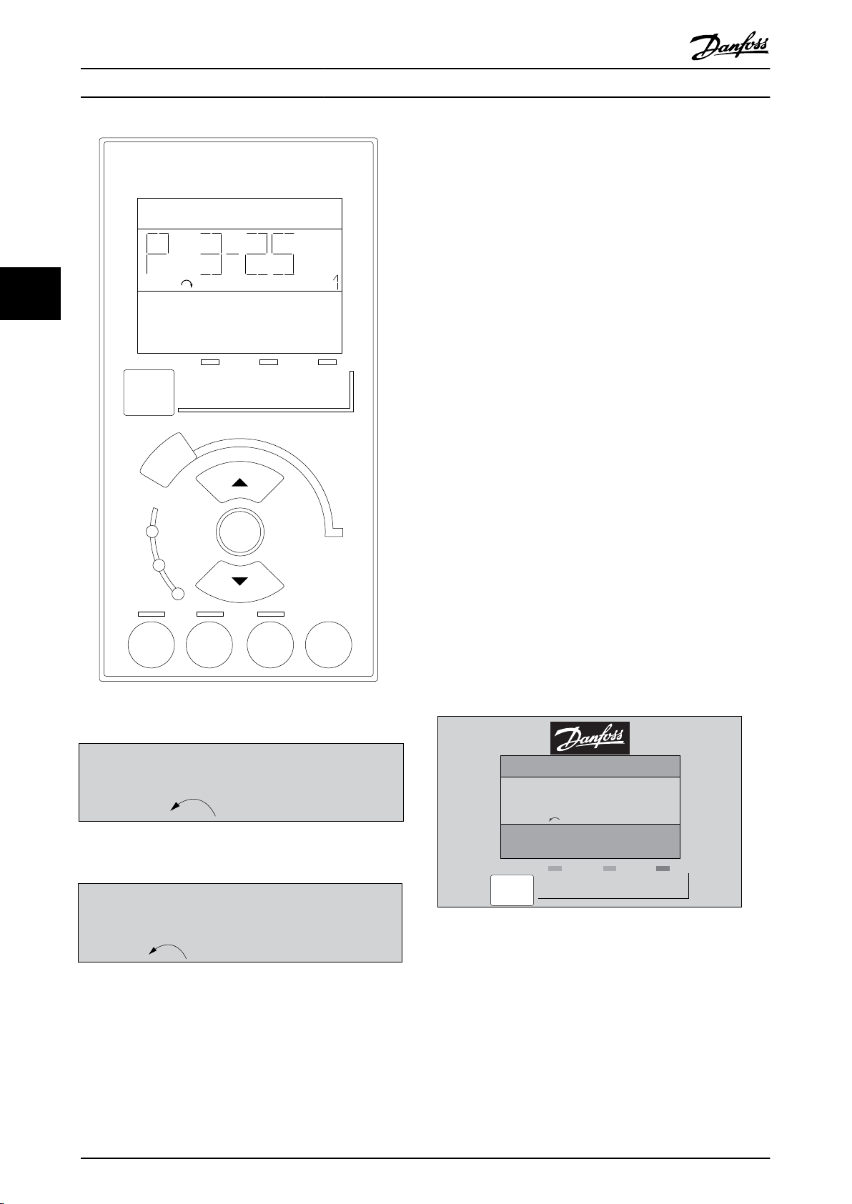
130BA191.10
1
Auto
on
Reset
Hand
on
O
Menu
Status
Quick
Setup
Main
Menu
Back
2
3
4
OK
On
Alarm
Warn.
Setup
130BP077.10
22.8
rpm
Setup 1
Setup 1
130BP078.10
A 17
130BP079.10
Menu
Status Quick
Setup
Main
Menu
P 2-03
Setup 1
How to operate the frequenc... VLT AQUA Drive FC 202 Operation Instructions
Menu key
Select one of the following modes:
Status
•
Quick Setup
•
Main Menu
•
Main Menu
is used for programming all parameters.
The parameters can be accessed immediately unless a
44
password has been created via 0-60 Main Menu Password,
0-61 Access to Main Menu w/o Password, 0-65 Personal Menu
Password or 0-66 Access to Personal Menu w/o Password.
Quick Setup is used to set up the frequency converter
using only the most essential parameters.
The parameter values can be changed using the up/down
arrows when the value is flashing.
Select Main Menu by pressing the [Menu] key a number of
times until the Main Menu LED is lit.
Select the parameter group [xx-__] and press [OK]
Select the parameter [__-xx] and press [OK]
If the parameter is an array parameter select the array
number and press [OK]
Select the wanted data value and press [OK]
Navigation keys
[Back]
for stepping backwards
[▲] [▼]
keys are used for manoeuvring between parameter groups,
parameters and within parameters
[OK]
Illustration 4.13 Numerical LCP (NLCP)
Illustration 4.14 Status display example
Illustration 4.15 Alarm display example
is used for choosing a parameter marked by the cursor
and for enabling the change of a parameter.
Illustration 4.16 Display example
Indicator lights (LEDs):
Green LED/On: Indicates if control section is on.
•
•
•
74 MG20P402 - Rev. 2013-12-16
Yellow LED/Wrn.: Indicates a warning.
Flashing red LED/Alarm: Indicates an alarm.

130BP046.10
Hand
on
O
Auto
on
Reset
130BP068.10
740RPM
0 -01 Language
[0] English
10.64 A 1 [1]
0-0
*
Basic Settings
130BP069.10
1- 6*
113 RPM 1.78 A 1(1)
Load depen. setting
1 - 60 Low speed load
compensation
100%
How to operate the frequenc... VLT AQUA Drive FC 202 Operation Instructions
Operation keys
Keys for local control are found at the bottom of the
control panel.
Illustration 4.17 Operation keys of the numerical LCP (NLCP)
[Hand on]
enables control of the frequency converter via the LCP.
[Hand on] also starts the motor and it is now possible to
enter the motor speed data by means of the navigation
keys. The key can be [1] Enabled or[0] Disabled via
0-40 [Hand on] Key on LCP.
External stop signals activated by means of control signals
or a serial bus will override a 'start' command via the LCP.
The following control signals are still active when [Hand
on] is activated:
[Hand on] - [Off] - [Auto on]
•
Reset
•
Coasting stop inverse
•
Reversing
•
Set-up select lsb - Set-up select msb
•
Stop command from serial communication
•
Quick stop
•
DC brake
•
[Off]
stops the connected motor. The key can be [1] Enabled or
[0] Disabled via 0-41 [Off] Key on LCP.
If no external stop function is selected and the [Off] key is
inactive the motor can be stopped by disconnecting the
mains supply.
[Auto on]
enables the frequency converter to be controlled via the
control terminals and/or serial communication. When a
start signal is applied on the control terminals and/or the
bus, the frequency converter starts. The key can be [1]
Enabled or [0] Disabled via 0-42 [Auto on] Key on LCP.
4.1.3
Changing Data
1. Press [Quick Menu] or [Main Menu] key.
2.
Press [▲] and [▼] to find parameter group to edit.
3. Press [OK] key.
4.
Press [▲] and [▼] to find parameter to edit.
5. Press [OK] key.
6.
Press [▲] and [▼] to select correct parameter
setting. Or, to move to digits within a number,
press keys. Cursor indicates digit selected to
change. [▲] increases the value, [▼] decreases the
value.
7. Press [Cancel] to disregard change, or press [OK]
to accept change and enter new setting.
Changing a Text Value
4.1.4
If the selected parameter is a text value, change the text
value with the [▲]/[▼] keys.
[▲] increases the value, and [▼] decreases the value. Place
the cursor on the value to be saved and press [OK].
Illustration 4.18 Display Example
4.1.5 Changing a Group of Numeric Data
Values
If the selected parameter represents a numeric data value,
change the selected data value with the [◄] and [►] keys
as well as the up/down [▲] [▼] keys. press [◄] and [►] to
move the cursor horizontally.
4 4
NOTICE
An active HAND-OFF-AUTO signal via the digital inputs
has higher priority than the control keys [Hand on] [Auto
on].
[Reset]
is used for resetting the frequency converter after an alarm
(trip). The key can be [1] Enabled or[0] Disabled via
0-43 [Reset] Key on LCP.
MG20P402 - Rev. 2013-12-16 75
Illustration 4.19 Display Example

130BP070.10
1 - 60 Low speed load
compensation
1 0%
Load depen. setting 1- 6*
729RPM 6.21A 1(1)
6
How to operate the frequenc...
VLT AQUA Drive FC 202 Operation Instructions
Press [▲] and [▼] to change the data value. [▲] increases
the data value, and [▼] decreases the data value. Place the
cursor on the value to be saved and press [OK].
Under [Quick Menu] and [Changes Made] all
•
parameters that have been changed from factory
settings are displayed.
Press and hold [Main Menu] key for 3 s for access
•
to any parameter.
For service purposes it is recommended to copy
•
all parameters to the LCP, see 0-50 LCP Copy for
further information.
44
Illustration 4.20 Display Example
4.1.6 Changing of Data Value, Step-by-Step
Certain parameters can be changed step by step or
infinitely variably. This applies to parameter 1-20 Motor
Power [kW], parameter 1-22 Motor Voltage and
parameter 1-23 Motor Frequency.
The parameters are changed both as a group of numeric
data values and as numeric data values infinitely variably.
Read-out and Programming of
4.1.7
Indexed Parameters
Parameters are indexed when placed in a rolling stack.
15-30 Alarm Log: Error Code to 15-32 Alarm Log: Time
contain a fault log which can be read out. Select a
parameter, press [OK], and use [▲] and [▼] to scroll
through the value log.
Use parameter 3-10 Preset Reference as another example:
Select the parameter, press [OK], and use [▲] and [▼] to
scroll through the indexed values. To change the
parameter value, select the indexed value and press [OK].
Change the value by [▲] and [▼]. Press [OK] to accept the
new setting. Press [Cancel] to abort. Press [Back] to leave
the parameter.
Tips and Tricks
4.1.8
For the majority of water and wastewater
•
applications the Quick Menu, Quick Set-up and
Function Set-up provides the simplest and
quickest access to all the typical parameters
required.
Whenever possible, performing an AMA, ensures
•
best shaft performance.
Contrast of the display can be adjusted by
•
pressing [Status] and [▲] for darker display or by
pressing [Status] and [▼] for brighter display.
4.1.9 Quick Transfer of Parameter Settings
when Using GLCP
Once the set-up of a frequency converter is complete, it is
recommended to store (back up) the parameter settings in
the GLCP or on a PC via MCT 10 Set-up Software Tool.
WARNING
Stop the motor before performing any of these
operations.
Data storage in LCP
1.
Go to 0-50 LCP Copy.
2. Press [OK].
3.
Select [1] All to LCP.
4. Press [OK].
All parameter settings are now stored in the GLCP
indicated by the progress bar. When 100% is reached,
press [OK].
The GLCP can now be connected to another frequency
converter and the parameter settings copied to this
frequency converter.
Data transfer from LCP to Frequency converter
1.
Go to 0-50 LCP Copy.
2. Press [OK].
3.
Select [2] All from LCP.
4. Press [OK]
The parameter settings stored in the GLCP are now
transferred to the frequency converter indicated by the
progress bar. When 100% is reached, press [OK].
4.1.10
There are 2 ways to initialise the frequency converter to
default: Recommended initialisation and manual initialisation.
Be aware that they have different impact according to the
below description.
Initialisation to Default Settings
76 MG20P402 - Rev. 2013-12-16

130BA060.11
68 69 68 69 68 69
RS 485
RS 232
USB
+
-
How to operate the frequenc... VLT AQUA Drive FC 202 Operation Instructions
Recommended initialisation (via 14-22 Operation Mode)
1.
Select 14-22 Operation Mode.
2. Press [OK].
3.
Select [2] Initialisation (for NLCP select “2”).
4. Press [OK].
5. Remove power to unit and wait for display to
turn off.
6. Reconnect power and the frequency converter is
reset. Note that first start-up takes a few more
seconds.
7. Press [Reset]
14-22 Operation Mode initialises all except:
14-50 RFI Filter
8-30 Protocol
8-31 Address
8-32 Baud Rate
8-35 Minimum Response Delay
8-36 Max Response Delay
8-37 Maximum Inter-Char Delay
15-00 Operating hours to 15-05 Over Volt's
15-20 Historic Log: Event to 15-22 Historic Log: Time
15-30 Alarm Log: Error Code to 15-32 Alarm Log: Time
4.1.11
One or more frequency converters can be connected to a
controller (or master) using the RS-485 standard interface.
Terminal 68 is connected to the P signal (TX+, RX+), while
terminal 69 is connected to the N signal (TX-,RX-).
If more than one frequency converter is connected to a
master, use parallel connections.
To avoid potential equalizing currents in the screen,
ground the cable screen via terminal 61, which is
connected to the frame via an RC-link.
RS-485 Bus Connection
Illustration 4.21 Connection Example.
4 4
NOTICE
Parameters selected in 0-25 My Personal Menu stay
present with default factory setting.
Manual initialisation
NOTICE
When carrying out manual initialisation, serial communication, RFI filter settings and fault log settings are reset.
Removes parameters selected in 0-25 My Personal Menu.
1. Disconnect from mains and wait until the display
turns off.
2. Press
2a [Status] - [Main Menu] - [OK] at the
same time while power up for Graphical
LCP (GLCP).
2b [Menu] while power up for LCP 101,
Numerical Display.
3. Release the keys after 5 s.
4. The frequency converter is now programmed
according to default settings.
This parameter initialises all except:
15-00 Operating hours
15-03 Power Up's
15-04 Over Temp's
15-05 Over Volt's
Bus termination
The RS-485 bus must be terminated by a resistor network
at both ends. If the frequency converter is the first or the
last device in the RS-485 loop, set the switch S801 on the
control card for ON.
For more information, see the paragraph Switches S201,
S202, and S801.
4.1.12
How to Connect a PC to the
Frequency Converter
To control or program the frequency converter from a PC,
install the PC-based configuration tool MCT 10 Set-up
Software.
The PC is connected via a standard (host/device) USB
cable, or via the RS-485 interface as shown in
chapter 4.1.11 RS-485 Bus Connection.
NOTICE
The USB connection is galvanically isolated from the
supply voltage (PELV) and other high-voltage terminals.
The USB connection is connected to protection earth.
Use only an isolated laptop as PC connection to the USB
connector on the frequency converter.
MG20P402 - Rev. 2013-12-16 77

130BT308.10
How to operate the frequenc...
VLT AQUA Drive FC 202 Operation Instructions
mains, in conjunction with the USB port. Failure
to do so may damage equipment.).
2. Open MCT 10 Set-up Software.
3.
Select Read from drive.
4.
Select Save as.
All parameters are now stored in the PC.
44
Illustration 4.22 USB Connection to Frequency Converter
4.1.13
PC-based MCT 10 Set-up Software
All Frequency converters are equipped with a serial
communication port. Danfoss provides a PC tool for
communication between PC and frequency converter, PCbased Configuration Tool MCT 10. Check the section on
Available Literature for detailed information on this tool.
MCT 10 set-up software
MCT 10 has been designed as an easy to use interactive
tool for setting parameters in our frequency converters. .
The MCT 10 Set-up Software is useful for:
MCT 10 Set-up Software supports Profibus DP-V1 via a
Master class 2 connection. It makes it possible to on line
read/write parameters in a frequency converter via the
Profibus network. This eliminates the need for an extra
communication network.
Save frequency converter settings:
PC Software Tools
Planning a communication network off-line. MCT
•
10 Set-up Software contains a complete
frequency converter database.
Commissioning frequency converters on line.
•
Saving settings for all frequency converters.
•
Replacing a frequency converter in a network.
•
Simple and accurate documentation of frequency
•
converter settings after commissioning.
Expanding an existing network.
•
Future developed frequency converters are
•
supported.
1. Connect a PC to the unit via USB com port.
(NOTE: Use a PC, which is isolated from the
Load frequency converter settings:
1. Connect a PC to the frequency converter via USB
com port.
2. Open MCT 10 Set-up Software.
3.
Select Open – stored files are shown.
4. Open the appropriate file.
5.
Select Write to drive.
All parameter settings are now transferred to the
frequency converter.
A separate manual for MCT 10 Set-up Software is available
from www.Danfoss.com/BusinessAreas/DrivesSolutions/
Softwaredownload/DDPC+Software+Program.htm.
The MCT 10 Set-up software modules
The following modules are included in the software
package.
MCT Set-up 10 Software
Setting parameters
Copy to and from frequency converters
Documentation and print out of parameter
settings incl. diagrams
Table 4.1
Ordering number:
Order the CD containing MCT 10 Set-up Software using
code number 130B1000.
The software can be downloaded from the Danfoss
internet site www.Danfoss.com/BusinessAreas/DrivesSolutions/Softwaredownload/DDPC+Software+Program.htm
Ext. user interface
Preventive Maintenance Schedule
Clock settings
Timed Action Programming
Smart Logic Controller Set-up
78 MG20P402 - Rev. 2013-12-16

How to programme the freque...
VLT AQUA Drive FC 202 Operation Instructions
5 How to programme the frequency converter
5.1 How to programme
The parameters are grouped into various parameter groups for easy selection of the correct parameter for optimized
frequency converter operation.
Overview of parameter groups
Group Title Function
0-** Operation/Display Parameters related to the fundamental functions of the frequency converter,
function of the LCP keys and configuration of the LCP display.
1-** Load/Motor Parameter group for motor settings.
2-** Brakes Parameter group for setting brake features in the frequency converter.
3-** Reference/Ramps Parameters for reference handling, definitions of limitations, and configuration of
the reaction of the frequency converter to changes.
4-** Limits/Warnings Parameter group for configuring limits and warnings.
5-** Digital In/Out Parameter group for configuring the digital inputs and outputs.
6-** Analog In/Out Parameter group for configuration of the analog inputs and outputs.
8-** Communication and Options Parameter group for configuring communications and options.
9-** Profibus Parameter group for Profibus-specific parameters (requires profibus option).
10-** DeviceNet Fieldbus Parameter group for DeviceNet-specific parameters (requires DeviceNet option).
13-** Smart Logic Parameter group for Smart Logic Control
14-** Special Functions Parameter group for configuring special frequency converter functions.
15-** Drive Information Parameter group containing frequency converter information such as operating
data, hardware configuration and software versions.
16-** Data Readouts Parameter group for data read-outs, e.g. actual references, voltages, control, alarm,
warning and status words.
18-** Info and Readouts This parameter group contains the last 10 Preventive Maintenance logs.
20-** Drive Closed Loop This parameter group is used for configuring the closed loop PID Controller that
controls the output frequency of the unit.
21-** Extended Closed Loop Parameters for configuring the three Extended Closed Loop PID Controllers.
22-** Application Functions These parameters monitor water applications.
23-** Time-based Functions These parameters are for actions needed to be performed on a daily or weekly
basis, e.g. different references for working hours/non-working hours.
24-** Application Functions 2 Parameters for the Drive Bypass.
25-** Basic Cascade Controller Functions Parameters for configuring the Basic Cascade Controller for sequence control of
multiple pumps.
26-** Analog I/0 Option MCB 109 Parameters for configuring the Analog I/0 Option MCB 109.
27-** Extended Cascade Control Parameters for configuring the Extended Cascade Control (MCO 101/MCO 102).
29-** Water Application Functions Parameters for setting water specific functions.
30-** Special Features Parameters for configuring the brake resistor value.
31-** Bypass Option Parameters for configuring the Bypass Option (MCO 104).
35-** Sensor Input Option Parameters for configuring the Sensor Input Option (MCB 114)
5 5
Table 5.1 Parameter Groups
Parameter descriptions and selections are displayed on the graphic (GLCP) or numeric (NLCP) in the display area. (See for
details.) Access the parameters by pressing the [Quick Menu] or [Main Menu] key on the control panel. The quick menu is
used primarily for commissioning the unit at start-up by providing those parameters necessary to start operation. The main
menu provides access to all parameters for detailed application programming.
MG20P402 - Rev. 2013-12-16 79

130BP064.10
Q1 My Personal Menu
Q2 Quick Setup
Q3 Function Setups
Q5 Changes Made
40.0% 4.84 A 1(1)
Quick Menus
How to programme the freque...
VLT AQUA Drive FC 202 Operation Instructions
All digital input/output and analog input/output terminals
are multifunctional. All terminals have factory default
functions suitable for the majority of water applications
but if other special functions are required, they must be
programmed in parameter group 5-** Digital In/out or 6-**
Analog In/out.
5.1.1 Quick Menu Mode
The GLCP provides access to all parameters listed under
the Quick Menus. To set parameters using the [Quick
Menu] key:
55
Pressing [Quick Menu] the list indicates the different areas
contained in the Quick menu.
Efficient parameter set-up for water applications
The parameters can easily be set up for the vast majority
of the water and wastewater applications only by using
the [Quick Menu].
Par. Designation [Units]
0-01 Language
1-20 Motor Power [kW]
1-22 Motor Voltage [V]
1-23 Motor Frequency [Hz]
1-24 Motor Current [A]
1-25 Motor Nominal Speed [RPM]
3-41 Ramp 1 Ramp up Time [s]
3-42 Ramp 1 Ramp down Time [s]
4-11 Motor Speed Low Limit [RPM]
4-13 Motor Speed High Limit [RPM]
1-29 Automatic Motor Adaptation (AMA)
Table 5.2 Quick Setup parameters.
See Chapter 5.2 Commonly Used Parameters - Explanations
If No Operation is selected in terminal 27 no connection to
+24 V on terminal 27 is necessary to enable start.
If Coast Inverse (factory default value) is selected in
Terminal 27, a connection to +24 V is necessary to enable
start.
The optimum way to set parameters through the [Quick
Menu] is by following the below steps:
1. Press [Quick Setup] for selecting basic motor
settings, ramp times, etc.
2. Press [Function Setups] for setting up the
NOTICE
For detailed parameter descriptions, see
chapter 5.2 Commonly Used Parameters - Explanations.
required functionality of the frequency converter
- if not already covered by the settings in [Quick
5.1.2 Q1 My Personal Menu
Setup].
3.
Select between General Settings, Open Loop
Settings and Closed Loop Settings.
It is recommended to do the set-up in the order listed.
Parameters defined by the user can be stored in Q1 My
Personal Menu.
Select My Personal Menu to display only the parameters,
which have been pre-selected and programmed as
personal parameters. For example, a pump or equipment
OEM may have pre-programmed these to be in My
Personal Menu during factory commissioning to make on
site commissioning/fine tuning simpler. These parameters
are selected in par. 0-25 My Personal Menu. Up to 20
different parameters can be defined in this menu.
Illustration 5.1 Quick Menu View
Parameter 20-21 Setpoint 1
Parameter 20-93 PID Proportional Gain
Parameter 20-94 PID Integral Time
Table 5.3 Q1 My Personal Menu
5.1.3
Q2 Quick Setup
The parameters in Q2 Quick Setup are the basic
parameters which are always needed to set-up the
frequency converter to operation.
80 MG20P402 - Rev. 2013-12-16

28.8%
14.4Hz
Auto Remote Running
5.66A
2.63kW
0kWh
1 (1)
130BT110.11
Status
130BT111.10
Q1 My Personal Menu
Q2 Quick Setup
Q3 Function Setups
Q5 Changes Made
13.7% 13.0A 1(1)
Quick Menus
130BT112.10
Q1 My Personal Menu
Q2 Quick Setup
Q3 Function Setups
Q5 Changes Made
69.3% 5.20A 1(1)
Quick Menus
130BA500.10
1190 RPM
Q3 - 1 General Settings
Q3 - 2 Open Loop Settings
Q3 - 3 Closed Loop Settings
0.000 1 (1)
Q3
Function Setups
130BA501.10
0.000 rpm
Q3 - 10 Clock Settings
Q3 - 11 Display Settings
Q3 - 12 Analog Output
Q3 - 13 Relays
0.000 1 (1)
Q3-1
General Settings
130BA502.10
0.000 rpm
6 - 50 Terminal 42 Output
(100) Output frequency
0.000 1 (1)
Q3-12
Analog Output
130BA503.10
0.000 rpm
6 - 50 Terminal 42 Output
(107) Speed
0.000 1 (1)
Q3-12
Analog Output
How to programme the freque... VLT AQUA Drive FC 202 Operation Instructions
Parameter number and name Unit
0-01 Language
Parameter 1-20 Motor Power [kW] kW
Parameter 1-22 Motor Voltage V
Parameter 1-23 Motor Frequency Hz
Parameter 1-24 Motor Current A
Illustration 5.4
Parameter 1-25 Motor Nominal Speed RPM
Parameter 3-41 Ramp 1 Ramp Up Time s
Parameter 3-42 Ramp 1 Ramp Down Time s
Parameter 4-11 Motor Speed Low Limit [RPM] RPM
4.
Function Set-ups choices appear. Select Q3-1
General Settings. Press [OK].
Parameter 4-13 Motor Speed High Limit [RPM] RPM
Parameter 1-29 Automatic Motor Adaptation (AMA)
Table 5.4 Q2 Quick Setup
Q3 Function Set-ups
5.1.4
Illustration 5.5
The Function Set-up provides quick and easy access to all
parameters required for the majority of water and
wastewater applications including variable torque, constant
5.
Press [▲]/[▼] keys to scroll down to i.e. Q3-12
Analog Outputs. Press [OK].
torque, pumps, dosing pumps, well pumps, booster
pumps, mixer pumps, aeration blowers and other pump
and fan applications. Amongst other features, it also
includes parameters for selecting which variables to display
on the LCP, digital preset speeds, scaling of analog
references, closed loop single zone and multi-zone
applications and specific functions related to water and
Illustration 5.6
wastewater applications.
5 5
How to access Function Set-up - example:
1. Turn on the frequency converter (On LED lights)
Illustration 5.2
2. Press the [Quick Menus] key (Quick Menus
choices appear).
Illustration 5.3
3.
Press [▲]/[▼] navigation keys to scroll down to
Function Set-ups. Press [OK].
6.
Select parameter 6-50 Terminal 42 Output. Press
[OK].
Illustration 5.7
7.
Press [▲]/[▼] keys to select between the different
choices. Press [OK].
Illustration 5.8
MG20P402 - Rev. 2013-12-16 81

How to programme the freque... VLT AQUA Drive FC 202 Operation Instructions
The Function Setup parameters are grouped in the following way:
Q3-10 Clock Settings Q3-11 Display Settings Q3-12 Analog Output Q3-13 Relays
0-70 Date and Time 0-20 Display Line 1.1 Small Parameter 6-50 Terminal 42 Output
0-71 Date Format 0-21 Display Line 1.2 Small Parameter 6-51 Terminal 42 Output
Min Scale
Parameter 0-72 Time Format 0-22 Display Line 1.3 Small Parameter 6-52 Terminal 42 Output
Max Scale
Parameter 0-74 DST/Summertime 0-23 Display Line 2 Large
Parameter 0-76 DST/Summertime
55
Start
Parameter 0-77 DST/Summertime
End
Table 5.5 Q3-1 General Settings
Q3-20 Digital Reference Q3-21 Analog Reference
Parameter 3-02 Minimum Reference Parameter 3-02 Minimum Reference
3-03 Maximum Reference 3-03 Maximum Reference
Parameter 3-10 Preset Reference Parameter 3-10 Preset Reference
5-13 Terminal 29 Digital Input Parameter 6-11 Terminal 53 High Voltage
5-14 Terminal 32 Digital Input Parameter 6-14 Terminal 53 Low Ref./Feedb. Value
5-15 Terminal 33 Digital Input Parameter 6-15 Terminal 53 High Ref./Feedb. Value
0-24 Display Line 3 Large
Parameter 0-37 Display Text 1
parameter 0-38 Display Text 2
parameter 0-39 Display Text 3
Relay 1 ⇒ 5-40 Function Relay
Relay 2 ⇒ 5-40 Function Relay
Option relay 7 ⇒
5-40 Function Relay
Option relay 8 ⇒
5-40 Function Relay
Option relay 9 ⇒
5-40 Function Relay
Q3-30 Feedback Settings Q3-31 PID Settings
Parameter 1-00 Configuration Mode Parameter 20-81 PID Normal/ Inverse Control
20-12 Reference/Feedback Unit Parameter 20-82 PID Start Speed [RPM]
Parameter 3-02 Minimum Reference Parameter 20-21 Setpoint 1
3-03 Maximum Reference Parameter 20-93 PID Proportional Gain
Parameter 6-20 Terminal 54 Low Voltage Parameter 20-94 PID Integral Time
Parameter 6-21 Terminal 54 High Voltage
Parameter 6-24 Terminal 54 Low Ref./Feedb. Value
Parameter 6-25 Terminal 54 High Ref./Feedb. Value
Parameter 6-00 Live Zero Timeout Time
Parameter 6-01 Live Zero Timeout Function
82 MG20P402 - Rev. 2013-12-16

130BP066.10
1107 RPM
0 -
**
Operation/Display
1 -
**
Load/Motor
2 -
**
Brakes
3 -
**
Reference / Ramps
3.84 A 1 (1)
Main menu
How to programme the freque... VLT AQUA Drive FC 202 Operation Instructions
5.1.5 Q5 Changes Made
Q5 Changes Made can be used for fault finding.
Select Changes made to get information about:
the last 10 changes. Use the up/down navigation
•
keys to scroll between the last 10 changed
parameters.
the changes made since default setting.
•
Select Loggings to get information about the display line
read-outs. The information is shown as graphs.
Only display parameters selected in parameter 0-20 Display
Line 1.1 Small and 0-24 Display Line 3 Large can be viewed.
It is possible to store up to 120 samples in the memory for
later reference.
Note that the parameters listed in Table 5.6 to Table 5.6 for
Q5 only serve as examples as they vary depending on the
programming of the particular frequency converter.
Parameter 20-94 PID Integral Time
Parameter 20-93 PID Proportional Gain
Parameter 20-93 PID Proportional Gain
Parameter 20-94 PID Integral Time
Analog Input 53
Analog Input 54
Lines 2 through 5 on the display show a list of parameter
groups which can be selected by toggling the up and
down keys.
Illustration 5.9 Display Example
Each parameter has a name and number which remain the
same regardless of the programming mode. In the Main
Menu mode, the parameters are divided into groups. The
first digit of the parameter number (from the left) indicates
the parameter group number.
All parameters can be changed in the Main Menu. The
configuration of the unit (parameter 1-00 Configuration
Mode) determines other parameters available for
programming. For example, selecting closed loop enables
additional parameters related to closed loop operation.
Option cards added to the unit enable additional
parameters associated with the option device.
Parameter Selection
5.1.8
5 5
5.1.6 Q6 Loggings
Q6 Loggings can be used for fault finding.
Notice that the parameters listed in Table 5.6 for Q6 only
serve as examples as they vary depending on the
programming of the particular frequency converter.
Reference
Analog Input 53
Motor Current
Frequency
Feedback
Energy Log
Trending Cont Bin
Trending Timed Bin
Trending Comparison
5.1.7 Main Menu Mode
Both the GLCP and NLCP provide access to the main menu
mode. Select the Main Menu mode by pressing the [Main
Menu] key. Illustration 5.9 shows the resulting read-out,
which appears on the display of the GLCP.
MG20P402 - Rev. 2013-12-16 83
In the Main Menu mode, the parameters are divided into
groups. Select a parameter group by means of the
navigation keys.
The following parameter groups are accessible:
Group no.
0-** Operation/Display
1-** Load/Motor
2-** Brakes
3-** References/Ramps
4-** Limits/Warnings
5-** Digital In/Out
6-** Analog In/Out
8-** Comm. and Options
9-** Profibus
10-** CAN Fieldbus
11-** LonWorks
13-** Smart Logic
14-** Special Functions
15-** FC Information
16-** Data Readouts
18-** Data Readouts 2
20-** FC Closed Loop
21-** Ext. Closed Loop
Parameter group

130BP067.10
740RPM
0 -01 Language
[0] English
10.64A 1 [1]
0-0
*
Basic Settings
How to programme the freque... VLT AQUA Drive FC 202 Operation Instructions
Group no. Parameter group
22-** Application Functions
23-** Time Actions
25-** Cascade Controller
26-** Analog I/O Option MCB 109
27-** Cascade CTL Option
29-** Water Application Functions
31-** Bypass Option
Table 5.6 Parameter Groups
After selecting a parameter group, select a parameter with
55
the navigation keys.
The middle section on the GLCP display shows the
parameter number and name as well as the selected
parameter value.
Illustration 5.10 Display Example
5.2 Commonly Used Parameters Explanations
5.2.1 Main Menu
The Main Menu includes all available parameters in the
frequency converter.
All parameters are grouped in a logic way with a group
name indicating the function of the parameter group.
All parameters are listed by name and number in
chapter 5.3 Parameter Menu Structure.
0-01 Language
Option: Function:
Defines the language to be used in the
display.
The frequency converter can be delivered
with 4 different language packages. English
and German are included in all packages.
English cannot be erased or manipulated.
[0] * English Part of Language packages 1 - 4
[1] German Part of Language packages 1 - 4
[2] French Part of Language package 1
[3] Danish Part of Language package 1
[4] Spanish Part of Language package 1
[5] Italian Part of Language package 1
[6] Swedish Part of Language package 1
[7] Dutch Part of Language package 1
[10] Chinese Language package 2
[20] Finnish Part of Language package 1
[22] English US Part of Language package 4
[27] Greek Part of Language package 4
[28] Portuguese Part of Language package 4
[36] Slovenian Part of Language package 3
[39] Korean Part of Language package 2
[40] Japanese Part of Language package 2
[41] Turkish Part of Language package 4
[42] Traditional
Chinese
[43] Bulgarian Part of Language package 3
[44] Serbian Part of Language package 3
[45] Romanian Part of Language package 3
[46] Hungarian Part of Language package 3
[47] Czech Part of Language package 3
[48] Polish Part of Language package 4
[49] Russian Part of Language package 3
[50] Thai Part of Language package 2
[51] Bahasa
Indonesian
Part of Language package 2
Part of Language package 2
All parameters included in the Quick Menus (Q1, Q2, Q3,
Q5 and Q6) can be found in the following.
0-20 Display Line 1.1 Small
Option: Function:
Some of the most used parameters for VLT® AQUA Drive
applications are also explained in the following section.
For a detailed explanation of all parameters, refer to the
VLT® AQUA Drive Programming Guide which is available at
[0] None No display value selected
[37] Display Text 1 Present control word
[38] Display Text 2 Enables an individual text string to be
www.danfoss.com/BusinessAreas/DrivesSolutions/
Documentations/Technical+Documentation.htm or by
ordering at the local Danfoss office.
[39] Display Text 3 Enables an individual text string to be
Parameters related to the fundamental functions of the
frequency converter, function of the LCP keys and configuration of the LCP display.
84 MG20P402 - Rev. 2013-12-16
[89] Date and Time
Readout
Select a variable for display in line 1,
left position.
written, for display in the LCP or to
be read via serial communication.
written, for display in the LCP or to
be read via serial communication.
Displays the current date and time.

How to programme the freque... VLT AQUA Drive FC 202 Operation Instructions
0-20 Display Line 1.1 Small
Option: Function:
[953] Profibus Warning
Word
[1005] Readout Transmit
Error Counter
[1006] Readout Receive
Error Counter
[1007] Readout Bus Off
Counter
[1013] Warning
Parameter
[1230] Warning
Parameter
[1500] Operating hours View the number of running hours of
[1501] Running Hours View the number of running hours of
[1502] kWh Counter View the mains power consumption
[1580] Fan Running
Hours
[1600] Control Word View the Control Word sent from the
[1601] Reference [Unit] Total reference (sum of digital/analog/
[1602] Reference [%] Total reference (sum of digital/analog/
[1603] Status Word Present status word
[1605] Main Actual Value
[%]
[1609] Custom Readout View the user-defined readouts as
[1610] Power [kW] Actual power consumed by the motor
[1611] Power [hp] Actual power consumed by the motor
[1612] Motor Voltage Voltage supplied to the motor.
[1613] Frequency Motor frequency, i.e. the output
[1614] Motor current Phase current of the motor measured
Displays Profibus communication
warnings.
View the number of CAN control
transmission errors since the last
power-up.
View the number of CAN control
receipt errors since the last power-up.
View the number of Bus Off events
since the last power-up.
View a DeviceNet-specific warning
word. One separate bit is assigned to
every warning.
the frequency converter.
the motor.
in kWh.
frequency converter via the serial
communication port in hex code.
preset/bus/freeze ref./catch up and
slow-down) in selected unit.
preset/bus/freeze ref./catch up and
slow-down) in percent.
One or more warnings in a Hex code
defined in 0-30 Custom Readout Unit,
0-31 Custom Readout Min Value and
0-32 Custom Readout Max Value.
in kW.
in hp.
frequency from the frequency
converter in Hz.
as effective value.
0-20 Display Line 1.1 Small
Option: Function:
[1615] Frequency [%] Motor frequency, i.e. the output
frequency from the frequency
converter in percent.
[1616] Torque [Nm] Present motor load as a percentage
of the rated motor torque.
[1617] Speed [RPM] Speed in RPM (revolutions per
minute) i.e. the motor shaft speed in
closed loop based on the entered
motor nameplate data, the output
frequency and the load on the
frequency converter.
[1618] Motor Thermal Thermal load on the motor, calculated
by the ETR function. See also
parameter group 1-9* Motor
Temperature.
[1622] Torque [%] Shows the actual torque produced, in
percentage.
[1630] DC Link Voltage Intermediate circuit voltage in the
frequency converter.
[1632] Brake Energy /s Present brake power transferred to an
external brake resistor.
Stated as an instantaneous value.
[1633] Brake Energy /2
min
[1634] Heatsink Temp. Present heat sink temperature of the
[1635] Inverter Thermal Percentage load of the inverters
[1636] Inv. Nom. Current Nominal current of the frequency
[1637] Inv. Max. Current Maximum current of the frequency
[1638] SL Controller
State
[1639] Control Card
Temp.
[1650] External
Reference
[1652] Feedback[Unit] Signal value in units from the
[1653] Digi Pot
Reference
Brake power transferred to an
external brake resistor. The mean
power is calculated continuously for
the most recent 120 seconds.
frequency converter. The cut-out limit
is 95 ±5 °C; cutting back in occurs at
70 ±5 °C.
converter
converter
State of the event executed by the
control
Temperature of the control card.
Sum of the external reference as a
percentage, i.e. the sum of analog/
pulse/bus.
programmed digital input(s).
View the contribution of the digital
potentiometer to the actual reference
Feedback.
5 5
MG20P402 - Rev. 2013-12-16 85

How to programme the freque... VLT AQUA Drive FC 202 Operation Instructions
0-20 Display Line 1.1 Small
Option: Function:
[1654] Feedback 1 [Unit] View the value of Feedback 1. See
also parameter group 20-0* Feedback.
[1655] Feedback 2 [Unit] View the value of Feedback 2. See
also parameter group 20-0* Feedback.
[1656] Feedback 3 [Unit] View the value of Feedback 3. See
also parameter group 20-0* Feedback.
[1658] PID Output [%] Returns the Drive Closed Loop PID
controller output value in percent.
55
[1659] Adjusted Setpoint Displays the actual operating set-
point after it is modified by flow
compensation. See parameter group
22-8* Flow Compensation.
[1660] Digital Input Displays the status of the digital
inputs. Signal low = 0; Signal high =
1.
Regarding order, see 16-60 Digital
Input. Bit 0 is at the extreme right.
[1661] Terminal 53
Switch Setting
[1662] Analog Input 53 Actual value at input 53 either as a
[1663] Terminal 54
Switch Setting
[1664] Analog Input 54 Actual value at input 54 either as
[1665] Analog Output 42
[mA]
[1666] Digital Output
[bin]
[1667] Pulse Input #29
[Hz]
[1668] Pulse Input #33
[Hz]
[1669] Pulse Output #27
[Hz]
[1670] Pulse Output #29
[Hz]
[1671] Relay Output
[bin]
[1672] Counter A View the present value of Counter A.
[1673] Counter B View the present value of Counter B.
[1675] Analog In X30/11 Actual value of the signal on input
Setting of input terminal 53. Current
= 0; Voltage = 1.
reference or protection value.
Setting of input terminal 54. Current
= 0; Voltage = 1.
reference or protection value.
Actual value at output 42 in mA. Use
parameter 6-50 Terminal 42 Output to
select the variable to be represented
by output 42.
Binary value of all digital outputs.
Actual value of the frequency applied
at terminal 29 as a pulse input.
Actual value of the frequency applied
at terminal 33 as a pulse input.
Actual value of pulses applied to
terminal 27 in digital output mode.
Actual value of pulses applied to
terminal 29 in digital output mode.
View the setting of all relays.
X30/11 (General Purpose I/O Card.
Option)
0-20 Display Line 1.1 Small
Option: Function:
[1676] Analog In X30/12 Actual value of the signal on input
X30/12 (General Purpose I/O Card.
Optional)
[1677] Analog Out X30/8
[mA]
[1678] Analog Out X45/1
[mA]
[1679] Analog Out X45/3
[mA]
[1680] Fieldbus CTW 1 Control word (CTW) received from the
[1682] Fieldbus REF 1 Main reference value sent with
[1684] Comm. Option
STW
[1685] FC Port CTW 1 Control word (CTW) received from the
[1686] FC Port REF 1 Status word (STW) sent to the Bus
[1690] Alarm Word One or more alarms in a Hex code
[1691] Alarm Word 2 One or more alarms in a Hex code
[1692] Warning Word One or more warnings in a Hex code
[1693] Warning Word 2 One or more warnings in a Hex code
[1694] Ext. Status Word One or more status conditions in a
[1695] Ext. Status Word2One or more status conditions in a
[1696] Maintenance
Word
[1830] Analog Input
X42/1
[1831] Analog Input
X42/3
Actual value at output X30/8 (General
Purpose I/O Card. Optional) Use
6-60 Terminal X30/8 Output to select
the variable to be shown.
Bus Master.
control word via the serial communications network e.g. from the BMS,
PLC or other master controller.
Extended fieldbus communication
option status word.
Bus Master.
Master.
(used for serial communications)
(used for serial communications)
(used for serial communications)
(used for serial communications)
Hex code (used for serial communications)
Hex code (used for serial communications)
The bits reflect the status for the
programmed Preventive Maintenance
Events in parameter group 23-1*
Maintenance.
Shows the value of the signal applied
to terminal X42/1 on the Analog I/O
card.
Shows the value of the signal applied
to terminal X42/3 on the Analog I/O
card.
86 MG20P402 - Rev. 2013-12-16

How to programme the freque... VLT AQUA Drive FC 202 Operation Instructions
0-20 Display Line 1.1 Small
Option: Function:
[1832] Analog Input
X42/5
[1833] Analog Out X42/7
[V]
[1834] Analog Out X42/9
[V]
[1835] Analog Out
X42/11 [V]
[1836] Analog Input
X48/2 [mA]
[1837] Temp. Input
X48/4
[1838] Temp. Input
X48/7
[1839] Temp. Input
X48/10
[1860] Digital Input 2
[2117] Ext. 1 Reference
[Unit]
[2118] Ext. 1 Feedback
[Unit]
[2119] Ext. 1 Output [%] The value of the output from
[2137] Ext. 2 Reference
[Unit]
[2138] Ext. 2 Feedback
[Unit]
[2139] Ext. 2 Output [%] The value of the output from
[2157] Ext. 3 Reference
[Unit]
[2158] Ext. 3 Feedback
[Unit]
[2159] Ext. 3 Output [%] The value of the output from
[2230] No-Flow Power The calculated No Flow Power for the
[2316] Maintenance Text
[2580] Cascade Status Status for the operation of the
[2581] Pump Status Status for the operation of each
Shows the value of the signal applied
to terminal X42/5 on the Analog I/O
card.
Shows the value of the signal applied
to terminal X42/7 on the Analog I/O
card.
Shows the value of the signal applied
to terminal X42/9 on the Analog I/O
card.
Shows the value of the signal applied
to terminal X42/11 on the Analog I/O
card.
The value of the reference for
extended Closed Loop Controller 1
The value of the feedback signal for
extended Closed Loop Controller 1
extended Closed Loop Controller 1
The value of the reference for
extended Closed Loop Controller 2
The value of the feedback signal for
extended Closed Loop Controller 2
extended Closed Loop Controller 2
The value of the reference for
extended Closed Loop Controller 3
The value of the feedback signal for
extended Closed Loop Controller 3
extended Closed Loop Controller 3
actual operating speed
Cascade Controller
individual pump controlled by the
Cascade Controller
0-20 Display Line 1.1 Small
Option: Function:
[2791] Cascade
Reference
[2792] % Of Total
Capacity
[2793] Cascade Option
Status
[2794] Cascade System
Status
[2795] Advanced
Cascade Relay
Output [bin]
[2796] Extended Cascade
Relay Output
[bin]
[2920] Derag Power[kW]
[2921] Derag Power[HP]
[3110] Bypass Status
Word
[3111] Bypass Running
Hours
[9920] HS Temp. (PC1)
[9921] HS Temp. (PC2)
[9922] HS Temp. (PC3)
[9923] HS Temp. (PC4)
[9924] HS Temp. (PC5)
[9925] HS Temp. (PC6)
[9926] HS Temp. (PC7)
[9927] HS Temp. (PC8)
[9951] PC Debug 0
[9952] PC Debug 1
[9953] PC Debug 2
[9954] PC Debug 3
[9955] PC Debug 4
[9956] Fan 1 Feedback
[9957] Fan 2 Feedback
[9958] PC Auxiliary Temp
[9959] Power Card
Temp.
Reference output for use with
follower drives.
Readout parameter to show the
system operating point as a %
capacity of total system capacity.
Readout parameter to show the status
of the cascade system.
0-21 Display Line 1.2 Small
Option: Function:
Select a variable for display in line 1,
middle position.
[1662] * Analog input53The options are the same as those listed
for par. 0-20 Display Line 1.1 Small.
5 5
MG20P402 - Rev. 2013-12-16 87

How to programme the freque... VLT AQUA Drive FC 202 Operation Instructions
0-22 Display Line 1.3 Small
Option: Function:
Select a variable for display in line 1,
right position.
[1614] * Motor
Current
The options are the same as those listed
for 0-20 Display Line 1.1 Small.
0-23 Display Line 2 Large
Option: Function:
Select a variable for display in line 2.
[1615] * Frequency The options are the same as those listed for
55
par. 0-20 Display Line 1.1 Small
0-24 Display Line 3 Large
Option: Function:
[1652] * Feedback [Unit] The options are the same as those
listed for 0-20 Display Line 1.1 Small.
Select a variable for display in line 2.
0-37 Display Text 1
Range: Function:
0 * [0 -
25 ]
In this parameter it is possible to write an
individual text string for display in the LCP or to be
read via serial communication. If to be displayed
permanently select Display Text 1 in 0-20 Display
Line 1.1 Small, 0-21 Display Line 1.2 Small,
0-22 Display Line 1.3 Small, 0-23 Display Line 2 Large
or 0-24 Display Line 3 Large. Press [▲] or [▼] to
change a character. Press [◀] and [▶] to move the
cursor. When a character is highlighted, it can be
changed. Press [▲] or [▼] to change a character. A
character can be inserted by placing the cursor
between 2 characters and pressing [▲] or [▼].
0-39 Display Text 3
Range: Function:
Line 1.1 Small, 0-21 Display Line 1.2 Small,
0-22 Display Line 1.3 Small, 0-23 Display Line 2 Large
or 0-24 Display Line 3 Large. Press [▲] or [▼] to
change a character. Press [◀] and [▶] to move the
cursor. When a character is highlighted by the
cursor, this character can be changed. A character
can be inserted by placing the cursor between 2
characters and pressing [▲] or [▼].
0-70 Date and Time
Range: Function:
Size
related*
[ 0 - 0 ] Sets the date and time of the internal
clock. The format to be used is set in
0-71 Date Format and parameter 0-72 Time
Format.
0-71 Date Format
Option: Function:
[0] YYYY-MM-DD Sets the date format to be used in the LCP.
[1] DD-MM-YYYY Sets the date format to be used in the LCP.
[2] MM/DD/YYYY Sets the date format to be used in the LCP.
0-72 Time Format
Option: Function:
Sets the time format to be used in the LCP.
[0] 24 h
[1] 12 h
0-74 DST/Summertime
Option: Function:
0-38 Display Text 2
Range: Function:
0 * [0 -
25 ]
In this parameter it is possible to write an
individual text string for display in the LCP or to be
read via serial communication. If to be displayed
permanently select Display Text 2 in 0-20 Display
Line 1.1 Small, 0-21 Display Line 1.2 Small,
0-22 Display Line 1.3 Small, 0-23 Display Line 2 Large
or 0-24 Display Line 3 Large. Press [▲] or [▼] to
change a character. Press [◀] and [▶] to move the
cursor. When a character is highlighted by the
cursor, this character can be changed. A character
can be inserted by placing the cursor between two
characters and pressing [▲] or [▼].
[0] Off
[2] Manual
0-76 DST/Summertime Start
Range: Function:
Size related* [ 0 - 0 ] Sets the date and time when
Choose how Daylight Saving Time/Summertime
should be handled. For manual DST/Summertime
enter the start date and end date in
parameter 0-76 DST/Summertime Start and
parameter 0-77 DST/Summertime End.
summertime/DST starts. The date is
programmed in the format selected in
0-71 Date Format.
0-39 Display Text 3
Range: Function:
0 * [0 -
25 ]
88 MG20P402 - Rev. 2013-12-16
In this parameter it is possible to write an
individual text string for display in the LCP or to be
read via serial communication. If to be displayed
permanently select Display Text 3 in 0-20 Display
0-77 DST/Summertime End
Range: Function:
Size related* [ 0 - 0 ] Sets the date and time when
summertime/DST ends. The date is
programmed in the format selected in
0-71 Date Format.

How to programme the freque...
VLT AQUA Drive FC 202 Operation Instructions
5.2.2 1-0* General Settings
Define whether the frequency converter operates in open
loop or closed loop.
1-00 Configuration Mode
Option: Function:
NOTICE
This parameter cannot be adjusted while
the motor is running.
[0] Open
Loop
[3] Closed
Loop
Motor speed is determined by applying a speed
reference or by setting desired speed when in
Hand Mode.
Open Loop is also used if the frequency converter
is of a closed loop control system based on an
external PID controller providing a speed reference
signal as output.
Motor Speed will be determined by a reference
from the built-in PID controller varying the motor
speed as of a closed loop control process (e.g.
constant pressure or flow). The PID controller must
be configured in parameter group 20-** Feedback
or via the Function Set-ups accessed by pressing
[Quick Menus].
NOTICE
When set for Closed Loop, the commands Reversing and
Start Reversing do not reverse the direction of the
motor.
1-20 Motor Power [kW]
Range: Function:
Size
related*
1-22 Motor Voltage
Range: Function:
Size
related*
1-23 Motor Frequency
Range: Function:
Size
related*
[ 0.09 -
2000.00
kW]
[ 10 1000 V]
[20 1000
Hz]
Enter the nominal motor power in kW
according to the motor nameplate data.
The default value corresponds to the
nominal rated output of the unit.
Depending on the choices made in
0-03 Regional Settings, either
parameter 1-20 Motor Power [kW] or
1-21 Motor Power [HP] is made invisible.
Enter the nominal motor voltage
according to the motor nameplate
data. The default value corresponds to
the nominal rated output of the unit.
Select the motor frequency value from the
motor nameplate data. For 87 Hz operation
with 230/400 V motors, set the nameplate
1-23 Motor Frequency
Range: Function:
data for 230 V/50 Hz. Adapt
parameter 4-13 Motor Speed High Limit [RPM]
and 3-03 Maximum Reference to the 87 Hz
application.
1-24 Motor Current
Range: Function:
Size
related*
[ 0.10 -
10000.00 A]
Enter the nominal motor current
value from the motor nameplate
data. This data is used for
calculating motor torque, motor
thermal protection etc.
1-25 Motor Nominal Speed
Range: Function:
Size related* [100 - 60000
RPM]
Enter the nominal motor speed
value from the motor nameplate
data. This data is used for
calculating automatic motor
compensations.
1-29 Automatic Motor Adaptation (AMA)
Option: Function:
NOTICE
This parameter cannot be adjusted
while the motor is running.
[0] Off No function
[1] Enable
Complete
AMA
[2] Enable
Reduced AMA
Performs AMA of the stator resistance RS, the
rotor resistance Rr, the stator leakage
reactance X1, the rotor leakage reactance X
and the main reactance Xh.
Performs a reduced AMA of the stator
resistance Rs in the system only. Select this
option if an LC filter is used between the
frequency converter and the motor.
NOTICE
Parameter 1-29 Automatic Motor Adaptation (AMA) have
no effect when 1-10 Motor Construction = [1] PM, non
salient SPM.
Activate the AMA function by pressing [Hand on] after
selecting [1] or [2]. See also the item Automatic Motor
Adaptation in the Design Guide. After a normal sequence,
the display reads: Press [OK] to finish AMA. After pressing
[OK], the frequency converter is ready for operation.
5 5
2
MG20P402 - Rev. 2013-12-16 89

P3-03
P3-02
0 50 100%
P3-10
130BB036.10
[P 5-13=Preset ref. bit 0]
Preset
[P 5-14=Preset ref. bit 1]
[P 5-15=Preset ref. bit 2]
10101010
76543210
29
12
(+24V)
11001100
32
11110000
33
130BA149.10
How to programme the freque... VLT AQUA Drive FC 202 Operation Instructions
NOTICE
For the best adaptation of the frequency
•
converter, run AMA on a cold motor
AMA cannot be performed while the motor is
•
running
NOTICE
Avoid generating external torque during AMA.
55
NOTICE
3-10 Preset Reference
Array [8]
Range: Function:
0 %* [-100 -
100 %]
Enter up to eight different preset references
(0-7) in this parameter, using array
programming. The preset reference is stated as
a percentage of the value Ref
Reference, for closed loop see 20-14 Maximum
Reference/Feedb.). When using preset references,
select Preset ref. bit 0/1/2 [16], [17] or [18] for
the corresponding digital inputs in parameter
group 5-1* Digital Inputs.
(3-03 Maximum
MAX
If one of the settings in parameter group 1-2* Motor
Data is changed, 1-30 Stator Resistance (Rs) to 1-39 Motor
Poles return to default settings.
NOTICE
Full AMA should be run without filter only while reduced
AMA should be run with filter.
See section: Application Examples > Automatic Motor
Adaptation in the Design Guide.
3-0* Reference Limits
5.2.3
3-02 Minimum Reference
Range: Function:
Size
related*
[ -999999.999 par. 3-03
ReferenceFeedbackUnit]
Enter the Minimum Reference. The
Minimum Reference is the lowest
value obtainable by summing all
references. The Minimum
Reference value and unit matches
the configuration choice made in
parameter 1-00 Configuration Mode
and 20-12 Reference/Feedback Unit,
respectively.
NOTICE
This parameter is used in
open loop only.
3-04 Reference Function
Option: Function:
[0] Sum Sums both external and preset reference
sources.
[1] External/
Preset
Use either the preset or the external reference
source.
Shift between external and preset via a
command on a digital input.
Illustration 5.11
Illustration 5.12
90 MG20P402 - Rev. 2013-12-16

130BA962.10
Motor Speed
Motor Speed
High
Low
Normal
Ramps
Initial
Ramp
Final
Ramp
Time
Speed
130BA961.10
Speed
Motor Speed
Normal
Check valve
Motor Speed
High
Low
Time
Ramp
End Speed
130BA961.10
Speed
Motor Speed
Normal
Check valve
Motor Speed
High
Low
Time
Ramp
End Speed
How to programme the freque... VLT AQUA Drive FC 202 Operation Instructions
3-41 Ramp 1 Ramp Up Time
Range: Function:
Size
related*
par
.3 − 41=
[ 0.10 3600 s]
tacc×nnom par
ref rpm
Enter the ramp-up time, i.e. the
acceleration time from 0 RPM to
parameter 1-25 Motor Nominal Speed.
Select a ramp-up time such that the
output current does not exceed the
current limit in 4-18 Current Limit during
ramping. See ramp-down time in
parameter 3-42 Ramp 1 Ramp Down Time.
.1 − 25
s
3-42 Ramp 1 Ramp Down Time
Range: Function:
Size
related*
[ 0.10 3600 s]
Enter the ramp-down time, i.e. the
deceleration time from
parameter 1-25 Motor Nominal Speed to 0
RPM. Select a ramp-down time such that no
over-voltage arises in the inverter due to
regenerative operation of the motor, and
such that the generated current does not
exceed the current limit set in 4-18 Current
Limit. See ramp-up time in
parameter 3-41 Ramp 1 Ramp Up Time.
3-85 Check Valve Ramp Time
Range: Function:
0 s* [0 -
60 s]
In order to protect ball check valves in a stop
situation, the check valve ramp can be utilized as a
slow ramp rate from parameter 4-11 Motor Speed
Low Limit [RPM] or 4-12 Motor Speed Low Limit [Hz],
to Check Valve Ramp End Speed, set by the user in
3-86 Check Valve Ramp End Speed [RPM] or
3-87 Check Valve Ramp End Speed [HZ]. When
3-85 Check Valve Ramp Time is different from 0
seconds, the Check Valve Ramp Time is effectuated
and will be used to ramp down the speed from
Motor Speed Low Limit to the Check Valve End
Speed in 3-86 Check Valve Ramp End Speed [RPM] or
3-87 Check Valve Ramp End Speed [HZ]. See
Illustration 5.14.
5 5
par
.3 − 42=
tdec×nnom par
ref rpm
.1 − 25
s
3-84 Initial Ramp Time
Range: Function:
0 s* [0 -
Illustration 5.13 Initial and Final Ramp Time
Enter the initial ramp up time from zero speed to
60 s]
Motor Speed Low Limit, parameter 4-11 Motor Speed
Low Limit [RPM] or 4-12 Motor Speed Low Limit [Hz].
Submersible deep well pumps can be damaged by
running below minimum speed. A fast ramp time
below minimum pump speed is recommended. This
parameter may be applied as a fast ramp rate from
zero speed to Motor Speed Low Limit. See
Illustration 5.13.
Illustration 5.14 Check Valve Ramp
3-86 Check Valve Ramp End Speed [RPM]
Range: Function:
Size related* [ 0 - par.
4-11 RPM]
Illustration 5.15
Set the speed in [RPM] below Motor
Speed Low Limit where the Check
Valve is expected to be closed and
the Check Valve should no longer
be active.
MG20P402 - Rev. 2013-12-16 91

130BA961.10
Speed
Motor Speed
Normal
Check valve
Motor Speed
High
Low
Time
Ramp
End Speed
130BA962.10
Motor Speed
Motor Speed
High
Low
Normal
Ramps
Initial
Ramp
Final
Ramp
Time
Speed
How to programme the freque...
VLT AQUA Drive FC 202 Operation Instructions
3-87 Check Valve Ramp End Speed [HZ]
Range: Function:
Size related* [ 0 - par. 4-12
Hz]
Set the speed in [Hz] below Motor
Speed Low Limit where the Check
Valve Ramp should no longer be
active.
4-11 Motor Speed Low Limit [RPM]
Range: Function:
parameter 4-13 Motor Speed High Limit
[RPM].
4-13 Motor Speed High Limit [RPM]
Range: Function:
Size
related*
55
Illustration 5.16
3-88 Final Ramp Time
Range: Function:
0 s* [0 -
Enter the Final Ramp Time to be used when
60 s]
ramping down from Motor Speed Low Limit,
parameter 4-11 Motor Speed Low Limit [RPM] or
4-12 Motor Speed Low Limit [Hz], to zero speed.
Submersible deep well pumps can be damaged by
running below minimum speed. A fast ramp time
below minimum pump speed is recommended. This
parameter may be applied as a fast ramp rate from
Motor Speed Low Limit to zero speed.
NOTICE
Max. output frequency cannot exceed 10% of the
inverter switching frequency (14-01 Switching Frequency).
NOTICE
Any changes in parameter 4-13 Motor Speed High Limit
[RPM] reset the value in 4-53 Warning Speed High to the
same value as set in parameter 4-13 Motor Speed High
Limit [RPM].
[ 0 60000
RPM]
Enter the maximum limit for motor speed.
The motor speed high limit can be set to
correspond to the manufacturer’s maximum
rated motor. The motor speed high limit
must exceed the setting in
parameter 4-11 Motor Speed Low Limit
[RPM]. Only parameter 4-11 Motor Speed
Low Limit [RPM] or 4-12 Motor Speed Low
Limit [Hz] is displayed depending on other
parameters in the Main Menu and
depending on default settings dependant
on global location.
5.2.5 5-** Digital In/Out
Illustration 5.17
5.2.4 4-** Limits and Warnings
4-11 Motor Speed Low Limit [RPM]
Range: Function:
Size
related*
92 MG20P402 - Rev. 2013-12-16
[ 0 - par.
4-13
RPM]
Enter the minimum limit for motor speed.
The motor speed low limit can be set to
correspond to the manufacturer’s
recommended minimum motor speed.
The motor speed low limit must not
exceed the setting in
Parameter group for configuring the digital input and
output.
5-01 Terminal 27 Mode
Option: Function:
NOTICE
This parameter cannot be adjusted while the
motor is running.
[0] Input Defines terminal 27 as a digital input.
[1] Output Defines terminal 27 as a digital output.
5.2.6 5-1* Digital Inputs
Parameters for configuring the input functions for the
input terminals.
The digital inputs are used for selecting various functions
in the frequency converter. All digital inputs can be set to
the following functions:

How to programme the freque...
VLT AQUA Drive FC 202 Operation Instructions
Options [120] - [138] are related to the Cascade Controller
functionality. For more information, see parameter group
25-** Cascade Controller.
Digital input function Option Terminal
No operation [0] All *term 32, 33, 29, 19
Reset [1] All
Coast inverse [2] All * term 27
Coast and reset inverse [3] All
DC-brake inverse [5] All
Stop inverse [6] All
External interlock [7] All
Start [8] All
Latched start [9] All
Reversing [10] All
Start reversing [11] All
Jog [14] All
Preset reference on [15] All
Preset ref bit 0 [16] All
Preset ref bit 1 [17] All
Preset ref bit 2 [18] All
Freeze reference [19] All
Freeze output [20] All
Speed up [21] All
Speed down [22] All
Set-up select bit 0 [23] All
Set-up select bit 1 [24] All
Pulse input [32] term 29, 33
Ramp bit 0 [34] All
Mains failure inverse [36] All
Ref source bit 0 [42] All
Hand/Auto Start [51] All
Run Permissive [52] All
Hand start [53] All
Auto start [54] All
DigiPot Increase [55] All
DigiPot Decrease [56] All
DigiPot Clear [57] All
Counter A (up) [60] 29, 33
Counter A (down) [61] 29, 33
Reset Counter A [62] All
Counter B (up) [63] 29, 33
Counter B (down) [64] 29, 33
Reset Counter B [65] All
Sleep Mode [66] All
Reset Maintenance Word [78] All
PTC Card 1 [80] All
Latched Pump Derag [85] All
Lead Pump Start [120] All
Lead Pump Alternation [121] All
Pump 1 Interlock [130] All
Pump 2 Interlock [131] All
Pump 3 Interlock [132] All
5 5
Table 5.7 Functions for Digital Inputs
All = Terminals 18, 19, 27, 29, 32, X30/2, X30/3, X30/4. X30/
are the terminals on MCB 101.
MG20P402 - Rev. 2013-12-16 93

How to programme the freque... VLT AQUA Drive FC 202 Operation Instructions
Functions dedicated to only one digital input are stated in
the associated parameter.
[8] Start Select start value for a start/stop command.
All digital inputs can be programmed to these functions:
[0] No operation No reaction to signals transmitted to
terminal.
[1] Reset Resets frequency converter after a TRIP/
ALARM. Not all alarms can be reset.
[2] Coast inverse
55
[3] Coast and
reset inverse
[5] DC-brake
inverse
[6] Stop inverse Stop Inverted function. Generates a stop
Leaves motor in free mode. Logic ‘0’ ⇒
coasting stop.
(Default Digital input 27): Coasting stop,
inverted input (NC).
Reset and coasting stop Inverted input (NC).
Leaves motor in free mode and resets the
frequency converter. Logic ‘0’ ⇒ coasting
stop and reset.
Inverted input for DC braking (NC).
Stops motor by energizing it with a DC
current for a certain time period. See
2-01 DC Brake Current to 2-03 DC Brake Cut
In Speed [RPM]. The function is only active
when the value in 2-02 DC Braking Time is
different from 0. Logic ’0’ ⇒ DC braking.
This selection is not possible when
1-10 Motor Construction is set to [1] PM, non
salient SPM
function when the selected terminal goes
from logical level ‘1’ to ‘0’. The stop is
performed according to the selected ramp
time (parameter 3-42 Ramp 1 Ramp Down
Time and 3-52 Ramp 2 Ramp Down Time.
[9] Latched start Motor starts, if a pulse is applied for min. 2
[10] Reversing Changes direction of motor shaft rotation.
[11] Start
reversing
[14] Jog
[15] Preset
reference on
[16] Preset ref bit0Enables a choice between one of the eight
[17] Preset ref bit1Enables a choice between one of the eight
[18] Preset ref bit2Enables a choice between one of the eight
NOTICE
When the frequency converter is at
the torque limit and has received a
stop command, it may not stop by
itself. To ensure that the frequency
converter stops, configure a digital
output to [27] Torque limit & stop and
connect this digital output to a digital
input that is configured as coast.
[7] External
Interlock
Same function as Coasting stop, inverse, but
External Interlock generates the alarm
message ’external fault’ on the display when
the terminal which is programmed for Coast
Inverse is logic ‘0’. The alarm message will
also be active via digital outputs and relay
outputs, if programmed for External
Interlock. The alarm can be reset using a
digital input or the [Reset] key if the cause
for the External Interlock has been removed.
A delay can be programmed in
22-00 External Interlock Delay. After applying
a signal to the input, the reaction described
[19] Freeze ref Freezes actual reference. The frozen
[20] Freeze output Freezes actual motor frequency (Hz). The
above will be delayed with the time set in
22-00 External Interlock Delay.
‘1’ = start, ‘0 ’ = stop.
(Default Digital input 18)
ms. Motor stops when Stop inverse is
activated
Select Logic ‘1’ to reverse. The reversing
signal only changes the direction of
rotation. It does not activate the start
function. Select both directions in
4-10 Motor Speed Direction.
(Default Digital input 19).
Used for start/stop and for reversing on the
same wire. Signals on start are not allowed
at the same time.
Used for activating jog speed. See 3-11 Jog
Speed [Hz].
(Default Digital input 29)
Used for shifting between external reference
and preset reference. It is assumed that [1]
External/preset has been selected in
parameter 3-04 Reference Function. Logic '0'
= external reference active; logic '1' = one
of the eight preset references is active.
preset references according to Table 5.8.
preset references according to Table 5.8.
preset references according to Table 5.8.
Preset ref. bit 2 1 0
Preset ref. 0 0 0 0
Preset ref. 1 0 0 1
Preset ref. 2 0 1 0
Preset ref. 3 0 1 1
Preset ref. 4 1 0 0
Preset ref. 5 1 0 1
Preset ref. 6 1 1 0
Preset ref. 7 1 1 1
Table 5.8 Preset Ref. Bit
reference is now the point of enable/
condition for Speed up and Speed down to
be used. If Speed up/down is used, the
speed change always follows ramp 2
(3-51 Ramp 2 Ramp Up Time and 3-52 Ramp
2 Ramp Down Time) in the range 0 3-03 Maximum Reference Maximum Reference.
frozen motor frequency is now the point of
94 MG20P402 - Rev. 2013-12-16

How to programme the freque... VLT AQUA Drive FC 202 Operation Instructions
enable/condition for Speed up and Speed
down to be used. If Speed up/down is used,
the speed change always follows ramp 2
(3-51 Ramp 2 Ramp Up Time and 3-52 Ramp
2 Ramp Down Time) in the range 0 -
parameter 1-23 Motor Frequency.
NOTICE
When Freeze output is active, the
frequency converter cannot be
stopped via a low ‘start [13]’ signal.
Stop the frequency converter via a
terminal programmed for [2] Coast
inverse or [3] Coast and reset, inverse.
[21] Speed up For digital control of the up/down speed is
desired (motor potentiometer). Activate this
function by selecting either Freeze reference
or Freeze output. When Speed up is
activated for less than 400 msec. the
resulting reference will be increased by
0.1%. If Speed up is activated for more than
400 msec. the resulting reference will ramp
according to Ramp 1 in
parameter 3-41 Ramp 1 Ramp Up Time.
[22] Speed down
[23] Set-up select
bit 0
[24] Set-up select
bit 1
[32] Pulse input Select Pulse input when using a pulse
[34] Ramp bit 0 Select which ramp to use. Logic “0” will
[36] Mains failure
inverse
[42] Ref source bit0An active input in bit 0 selects AI54 as the
[51] Hand/Auto
Start
[52] Run
Permissive
Same as [21] Speed up.
Selects one of the four set-ups. Set
0-10 Active Set-up to Multi Set-up.
Same as [23] Set-up select bit 0.
(Default Digital input 32)
sequence as either reference or feedback.
Scaling is done in parameter group 5-5*.
select ramp 1 while logic “1” will select
ramp 2.
Activates 14-10 Mains Failure. Mains failure
inverse is active in the Logic “0” situation.
reference source (see parameter group 3-1*
References, option [35] Digital input select).
An inactive input selects AI53.
Selects Hand or Auto Start. High = Auto On
only, Low = Hand on only.
The input terminal, for which the Run
permissive has been programmed must be
logic “1” before a start command can be
accepted. Run permissive has a logic ‘AND’
function related to the terminal which is
programmed for [8] Start, [14] Jog or [20]
Freeze Output, which means that in order to
start running the motor, both conditions
must be fulfilled. If Run Permissive is
programmed on multiple terminals, Run
permissive needs only be logic ‘1’ on one of
the terminals for the function to be carried
out. The digital output signal for Run
Request ([8] Start, [14] Jog or [20] Freeze
output) programmed in parameter group
5-3* Digital outputs, or parameter group
5-4* Relays, will not be affected by Run
Permissive.
[53] Hand start A signal applied will put the frequency
converter into Hand mode as if [Hand On]
has been pressed and a normal stop
command will be overridden. If disconnecting the signal, the motor will stop. To
make any other start commands valid,
another digital input must be assign to Auto
Start and a signal applied to this. [Hand On]
and [Auto On] have no impact. [Off] will
override Hand Start and Auto Start. Press
either [Hand On] or [Auto On] to make Hand
Start and Auto Start active again. If no signal
on neither Hand Start nor Auto Start, the
motor will stop regardless of any normal
Start command applied. If signal applied to
both Hand Start and Auto Start, the function
will be Auto Start. If pressing [Off] the motor
will stop regardless of signals on Hand Start
and Auto Start.
[54] Auto start A signal applied will put the frequency
converter into Auto mode as if [Auto On]
has been pressed. See also [53] Hand Start.
[55] DigiPot
Increase
[56] DigiPot
Decrease
[57] DigiPot Clear Uses the input to CLEAR the Digital Potenti-
[60] Counter A
(up)
[61] Counter A
(down)
[62] Reset CounterAInput for reset of counter A.
[63] Counter B
(up)
[64] Counter B
(down)
[65] Reset CounterBInput for reset of counter B.
[66] Sleep Mode Forces frequency converter into Sleep Mode
[78] Reset
Preventive
Maintenance
Word
[80] PTC Card1
Uses the input as an INCREASE signal to the
Digital Potentiometer function described in
parameter group 3-9*
Uses the input as a DECREASE signal to the
Digital Potentiometer function described in
parameter group 3-9*
ometer reference described in parameter
group 3-9*
(Terminal 29 or 33 only) Input for increment
counting in the SLC counter.
(Terminal 29 or 33 only) Input for
decrement counting in the SLC counter.
(Terminal 29 and 33 only) Input for
increment counting in the SLC counter.
(Terminal 29 and 33 only) Input for
decrement counting in the SLC counter.
(see parameter group 22-4*, Sleep Mode).
Reacts on the rising edge of signal applied!
Resets all data in 16-96 Maintenance Word to
0.
All Digital Inputs can be set to [80] PTC Card
1. However, only one Digital Input must be
set to this choice.
5 5
MG20P402 - Rev. 2013-12-16 95

How to programme the freque... VLT AQUA Drive FC 202 Operation Instructions
[85] Latched
Pump Derag
Options [120] - [138] are related to the Cascade Controller
functionality. For more information, see parameter group
25-** Cascade Controller.
[120] Lead Pump
Start
55
[121] Lead Pump
Alternation
[130
Pump1
-
Interlock -
138]
Pump9
Interlock
Starts deragging.
Starts/Stops the Lead Pump (controlled by
the frequency converter). A start requires
that also a System Start signal has been
applied e.g. to one of the digital inputs set
for [8] Start!
Forces alternation of the lead pump in a
Cascade Controller. Lead Pump Alternation,
25-50 Lead Pump Alternation must be set to
either [2] At Command or [3] At Staging or
At Command. 25-51 Alternation Event can be
set to any of the four options.
The function depends on the setting in
25-06 Number of Pumps. If set to [0] No,
then Pump1 refers to the pump controlled
by relay RELAY1 etc. If set to [1] Yes, Pump1
refers to the pump controlled by the
frequency converter only (without any of
the build in relays involved) and Pump2 to
the pump controlled by the relay RELAY1.
Variable speed pump (lead) cannot be
interlocked in the basic Cascade Controller.
See Table 5.9
Setting in
parameter
group 5-1*
[130] Pump1
Interlock
[131] Pump2
Interlock
[132] Pump3
Interlock
[133] Pump4
Interlock
[134] Pump5
Interlock
[135] Pump6
Interlock
[136] Pump7
Interlock
[137] Pump8
Interlock
[138] Pump9
Interlock
Table 5.9
Setting in 25-06 Number of
Pumps
[0] No [1] Yes
Controlled
by RELAY1
(only if not
lead pump)
Controlled
by RELAY2
Controlled
by RELAY3
Controlled
by RELAY4
Controlled
by RELAY5
Controlled
by RELAY6
Controlled
by RELAY7
Controlled
by RELAY8
Controlled
by RELAY9
Frequency
Converter
controlled
(cannot be
interlocked)
Controlled
by RELAY1
Controlled
by RELAY2
Controlled
by RELAY3
Controlled
by RELAY4
Controlled
by RELAY5
Controlled
by RELAY6
Controlled
by RELAY7
Controlled
by RELAY8
5-13 Terminal 29 Digital Input
Option: Function:
[0] * No Operation Same options and functions as parameter
group 5-1* Digital Inputs.
5-14 Terminal 32 Digital Input
The parameter contains all options and functions listed in
parameter group chapter 5.2.6 5-1* Digital Inputs except for
option [32] Pulse input.
5-15 Terminal 33 Digital Input
The parameter contains all options and functions listed in
parameter group chapter 5.2.6 5-1* Digital Inputs.
5-30 Terminal 27 Digital Output
Option: Function:
[0] No operation
[1] Control Ready
[2] Drive ready
[3] Drive rdy/rem ctrl
[4] Stand-by / no warning
[5] Running
[6] Running / no warning
[8] Run on ref/no warn
[9] Alarm
[10] Alarm or warning
[11] At torque limit
[12] Out of current range
[13] Below current, low
[14] Above current, high
[15] Out of speed range
[16] Below speed, low
[17] Above speed, high
[18] Out of feedb. range
[19] Below feedback, low
[20] Above feedback, high
[21] Thermal warning
[25] Reverse
[26] Bus OK
[27] Torque limit & stop
[28] Brake, no brake war
[29] Brake ready, no fault
[30] Brake fault (IGBT)
[33] Safe stop active
[35] External Interlock
[40] Out of ref range
[41] Below reference, low
[42] Above ref, high
[45] Bus ctrl.
[46] Bus ctrl, 1 if timeout
[47] Bus ctrl, 0 if timeout
[55] Pulse output
[60] Comparator 0
[61] Comparator 1
[62] Comparator 2
96 MG20P402 - Rev. 2013-12-16

How to programme the freque... VLT AQUA Drive FC 202 Operation Instructions
5-30 Terminal 27 Digital Output
Option: Function:
[63] Comparator 3
[64] Comparator 4
[65] Comparator 5
[70] Logic rule 0
[71] Logic rule 1
[72] Logic rule 2
[73] Logic rule 3
[74] Logic rule 4
[75] Logic rule 5
[80] SL digital output A
[81] SL digital output B
[82] SL digital output C
[83] SL digital output D
[84] SL digital output E
[85] SL digital output F
[90] kWh counter pulse Creates a pulse on the digital
output every time when the
frequency converter uses 1 kWh.
[155] Verifying Flow
[160] No alarm
[161] Running reverse
[164] Local ref active, not OFF
[165] Local ref active
[166] Remote ref active
[167] Start command activ
[168] Hand mode
[169] Auto mode
[180] Clock Fault
[181] Prev. Maintenance
[182] Deragging
[183] Pre/Post Lube
[188] AHF Capacitor Connect
[189] External Fan Control
[190] No-Flow
[191] Dry Pump
[192] End Of Curve
[193] Sleep Mode
[194] Broken Belt
[195] Bypass Valve Control
[198] Drive Bypass
[199] Pipe Filling
[200] Full capacity
[201] Pump 1 running
[202] Pump 2 running
[203] Pump 3 running
[204] Pump 4 running
[205] Pump 5 running
[206] Pump 6 running
[207] Pump 7 running
[208] Pump 8 running
[209] Pump 9 running
5-40 Function Relay
Option: Function:
Select options to define the
function of the relays.
The selection of each mechanical
relay is realized in an array
parameter.
[0] No operation
[1] Control Ready
[2] Drive ready
[3] Drive rdy/rem ctrl
[4] Stand-by / no warning
[5] Running
[6] Running / no warning
[8] Run on ref/no warn
[9] Alarm
[10] Alarm or warning
[11] At torque limit
[12] Out of current range
[13] Below current, low
[14] Above current, high
[15] Out of speed range
[16] Below speed, low
[17] Above speed, high
[18] Out of feedb. range
[19] Below feedback, low
[20] Above feedback, high
[21] Thermal warning
[25] Reverse
[26] Bus OK
[27] Torque limit & stop
[28] Brake, no brake war
[29] Brake ready, no fault
[30] Brake fault (IGBT)
[33] Safe stop active
[35] External Interlock
[36] Control word bit 11
[37] Control word bit 12
[40] Out of ref range
[41] Below reference, low
[42] Above ref, high
[45] Bus ctrl.
[46] Bus ctrl, 1 if timeout
[47] Bus ctrl, 0 if timeout
[60] Comparator 0
[61] Comparator 1
[62] Comparator 2
[63] Comparator 3
[64] Comparator 4
[65] Comparator 5
[70] Logic rule 0
[71] Logic rule 1
[72] Logic rule 2
[73] Logic rule 3
5 5
MG20P402 - Rev. 2013-12-16 97

How to programme the freque... VLT AQUA Drive FC 202 Operation Instructions
5-40 Function Relay
5.2.7 6-** Analog In/Out
Option: Function:
[74] Logic rule 4
[75] Logic rule 5
[80] SL digital output A
[81] SL digital output B
[82] SL digital output C
[83] SL digital output D
[84] SL digital output E
[85] SL digital output F
[155] Verifying Flow
55
[160] No alarm
[161] Running reverse
[164] Local ref active, not OFF
[165] Local ref active
[166] Remote ref active
[167] Start command activ
[168] Hand mode
[169] Auto mode
[180] Clock Fault
[181] Prev. Maintenance
[183] Pre/Post Lube
[188] AHF Capacitor Connect
[189] External Fan Control
[190] No-Flow
[191] Dry Pump
[192] End Of Curve
[193] Sleep Mode
[194] Broken Belt
[195] Bypass Valve Control
[198] Drive Bypass
[199] Pipe Filling
[211] Cascade Pump 1
[212] Cascade Pump 2
[213] Cascade Pump 3
[214] Cascade Pump 4
[215] Cascade Pump 5
[216] Cascade Pump 6
[217] Cascade Pump 7
[218] Cascade Pump 8
[219] Cascade Pump 9
[230] Ext. Cascade Ctrl
Parameter group for configuration of the analog input and
output.
6-00 Live Zero Timeout Time
Range: Function:
10 s* [1 -
Enter the Live Zero Time-out time period. Live
99 s]
Zero Time-out Time is active for analog inputs, i.e.
terminal 53 or terminal 54, used as reference or
feedback sources. If the reference signal value
associated with the selected current input falls
below 50% of the value set in
parameter 6-10 Terminal 53 Low Voltage,
6-12 Terminal 53 Low Current,
parameter 6-20 Terminal 54 Low Voltage or
6-22 Terminal 54 Low Current for a time period
longer than the time set in parameter 6-00 Live
Zero Timeout Time, the function selected in
parameter 6-01 Live Zero Timeout Function is
activated.
5-53 Term. 29 High Ref./Feedb. Value
Range: Function:
100 * [-999999.999 -
999999.999 ]
98 MG20P402 - Rev. 2013-12-16
Enter the high reference value
[RPM] for the motor shaft speed
and the high feedback value, see
also 5-58 Term. 33 High Ref./Feedb.
Value.
 Loading...