

MAKING MODERN LIVING POSSIBLE
Instruction Manual 12-Pulse High Power
VLT® AQUA Drive FC 200


Contents VLT AQUA 12-Pulse High Power Instruction Manual
Contents
1 How to Read the Instruction Manual
1.1.1 Copyright, Limitation of Liability and Revision Rights 1-1
1.1.3 Approvals 1-1
2 Safety
2.1.1 High Voltage 2-1
2.1.2 Safety Instructions 2-1
2.1.5 Avoid Unintended Start 2-2
2.1.6 Safe Stop 2-2
2.1.8 IT Line Power 2-3
3 Mechanical Installation
3.1 Pre-installation
3.1.1 Planning the Installation Site 3-1
3.1.2 Receiving the Adjustable Frequency Drive 3-1
3.1.3 Transportation and Unpacking 3-1
3.1.4 Lifting 3-1
3.1.5 Mechanical Dimensions 3-3
1-1
2-1
3-1
3-1
3.2 Mechanical Installation
3.2.3 Terminal Locations, F8-F13 3-8
3.2.4 Cooling and Airflow 3-14
3.3 Frame size F Panel Options
4 How to Install
4.1 Electrical Installation
4.1.1 Power Connections 4-1
4.1.6 Shielded Cables 4-9
4.1.9 AC line input connections 4-11
4.1.11 Fuses 4-12
4.1.13 Motor Bearing Currents 4-14
4.1.14 Control Cable Routing 4-14
4.1.16 Electrical Installation, Control Terminals 4-15
4.2 Connection Examples
4.2.1 Start/Stop 4-17
4.2.2 Pulse Start/Stop 4-17
4.3 Electrical Installation - additional
3-7
3-17
4-1
4-1
4-17
4-19
4.3.1 Electrical Installation, Control Cables 4-19
4.3.2 Switches S201, S202, and S801 4-22
MG.20.Y1.22 - VLT® is a registered Danfoss trademark

Contents VLT AQUA 12-Pulse High Power Instruction Manual
4.4 Final Set-up and Test
4.5 Additional Connections
5 How to operate the adjustable frequency drive
5.1.2 How to operate the Graphical LCP (GLCP) 5-1
5.1.8 Tips and tricks 5-6
6 How to program the adjustable frequency drive
6.1 How to program
6.2 Commonly Used Parameters - Explanations
6.2.1 Main Menu 6-7
6.3 Parameter Options
6.3.1 Default settings 6-34
6.3.2 Operation/Display 0-** 6-35
6.3.3 Load/Motor 1-** 6-37
6.3.4 Brakes 2-** 6-39
6.3.5 Reference / Ramps 3-** 6-40
6.3.6 Limits / Warnings 4-** 6-41
4-22
4-23
5-1
6-1
6-1
6-7
6-34
6.3.7 Digital In/Out 5-** 6-42
6.3.8 Analog In/Out 6-** 6-44
6.3.9 Comm. and Options 8-** 6-46
6.3.10 Profibus 9-** 6-47
6.3.11 CAN Fieldbus 10-** 6-48
6.3.12 Smart Logic 13-** 6-49
6.3.13 Special Functions 14-** 6-50
6.3.14 Adj. Freq. Drive Information 15-** 6-51
6.3.15 Data Readouts 16-** 6-53
6.3.16 Data Readouts 2 18-** 6-55
6.3.17 Adj. Freq. Drive Closed-loop 20-** 6-56
6.3.18 Ext. Closed-loop 21-** 6-57
6.3.19 Application Functions 22-** 6-59
6.3.20 Timed Actions 23-** 6-61
6.3.21 Cascade Controller 25-** 6-62
6.3.22 Analog I/O Option MCB 109 26-** 6-64
6.3.24 Water Application Functions 29-** 6-67
6.3.25 Bypass Option 31-** 6-67
7 General Specifications
8 Troubleshooting
MG.20.Y1.22 - VLT® is a registered Danfoss trademark
7-1
8-1

Contents VLT AQUA 12-Pulse High Power Instruction Manual
9 Index
9-1
MG.20.Y1.22 - VLT® is a registered Danfoss trademark

Contents VLT AQUA 12-Pulse High Power Instruction Manual
MG.20.Y1.22 - VLT® is a registered Danfoss trademark
How to Read the Instruction... VLT AQUA 12-Pulse High Power Instruction Manual
1 How to Read the Instruction Manual
1 1
1.1.1 Copyright, Limitation of Liability and
Revision Rights
This publication contains information proprietary to
Danfoss. By accepting and using this manual, the user
agrees that the information contained herein will be used
solely for operating equipment from Danfoss or equipment
from other vendors provided that such equipment is
intended for communication with Danfoss equipment over
a serial communication link. This publication is protected
under the copyright laws of Denmark and most other
countries.
Danfoss does not warrant that a software program
produced according to the guidelines provided in this
manual will function properly in every physical, hardware
or software environment.
Although Danfoss has tested and reviewed the documentation within this manual, Danfoss makes no warranty or
representation, neither expressed nor implied, with respect
to this documentation, including its quality, performance,
or fitness for a particular purpose.
NOTE!
Indicates something to be noted by the reader.
CAUTION
Indicates a general warning.
WARNING
Indicates a high-voltage warning.
Indicates default setting
✮
1.1.3 Approvals
In no event shall Danfoss be liable for direct, indirect,
special, incidental, or consequential damages arising out of
the use, or the inability to use information contained in
this manual, even if advised of the possibility of such
damages. In particular, Danfoss is not responsible for any
costs, including but not limited to those incurred as a
result of lost profits or revenue, loss or damage of
equipment, loss of computer programs, loss of data, the
costs to substitute these, or any claims by third parties.
Danfoss reserves the right to revise this publication at any
time and to make changes to its contents without prior
notice or any obligation to notify former or present users
of such revisions or changes.
It has been assumed that all devices will be sitting behind
a firewall that does packet filtering and the environment
has well-implemented restrictions on the software that can
run inside the firewall. All nodes are assumed to be
"trusted" nodes.
1.1.2
Symbols
Symbols used in this manual
1.1.4
Available literature for VLT® AQUA
Drive FC 200
-
VLT® AQUA Drive Instruction Manual MG.20.Mx.yy
provides the neccessary information for getting
the drive up and running.
-
VLT® AQUA Drive High Power Instruction Manual
MG.20.Px.yy provides the neccessary information
for getting the HP drive up and running.
-
VLT® AQUA Drive Design Guide MG.20.Nx.yy
contains all the technical information about the
drive and customer design and applications.
-
VLT® AQUA Drive Programming Guide MN.
20.Ox.yy provides information on how to program
and includes complete parameter descriptions.
-
VLT® AQUA Drive FC 200 Profibus MG.33.Cx.yy
-
VLT® AQUA Drive FC 200 DeviceNet MG.33.Dx.yy
- Output Filters Design Guide MG.90.Nx.yy
-
VLT® AQUA Drive FC 200 Cascade Controller MI.
38.Cx.yy
- Application Note MN20A102: Submersible Pump
Application
MG.20.Y1.22 - VLT® is a registered Danfoss trademark 1-1
How to Read the Instruction... VLT AQUA 12-Pulse High Power Instruction Manual
11
- Application Note MN20B102: Master/Follower
Operation Application
- Application Note MN20F102: Drive Closed-loop
and Sleep Mode
- Instruction MI.38.Bx.yy: Installation Instruction for
Mounting Brackets Enclosure type A5, B1, B2, C1
and C2 IP21, IP55 or IP66
- Instruction MI.90.Lx.yy: Analog I/O Option
MCB109
1.1.5 Abbreviations and Standards
Abbreviations: Terms: SI units: I-P units:
a Acceleration
AWG American wire gauge
Auto Tune Automatic Motor Tuning
°C
I Current A Amp
I
LIM
DCT Drive Control Tool
Joule Energy J = N∙m ft-lb, Btu
°F
f Frequency Hz Hz
kHz Kilohertz kHz kHz
mA Milliampere
ms Millisecond
min Minute
M-TYPE Motor Type Dependent
Nm Newton meters in-lbs
I
M,N
f
M,N
P
M,N
U
M,N
par. Parameter
PELV Protective Extra Low Voltage
Watt Power W Btu/hr, hp
Pascal Pressure Pa = N/m² psi, psf, ft of water
I
INV
RPM Revolutions Per Minute
SR Size Related
T Temperature C F
t Time s s, hr
Celsius
Current limit
Fahrenheit
Nominal motor current
Nominal motor frequency
Nominal motor power
Nominal motor voltage
Rated Drive Output Current
- Instruction MI.33.Hx.yy: Panel through mount kit
x = Revision number
yy = Language code
Danfoss technical literature is also available online at
www.danfoss.com/BusinessAreas/DrivesSolutions/Documentations/Technical+Documentation.htm.
m/s
2
ft/s
2
T
LIM
U Voltage V V
Table 1.1 Abbreviation and Standards table
1-2 MG.20.Y1.22 - VLT® is a registered Danfoss trademark
Torque limit

How to Read the Instruction... VLT AQUA 12-Pulse High Power Instruction Manual
1.1.6 Disposal Instructions
Equipment containing electrical components
may not be disposed of together with domestic
waste.
It must be separately collected with electrical
and electronic waste according to local and
currently valid legislation.
1 1
MG.20.Y1.22 - VLT® is a registered Danfoss trademark 1-3

How to Read the Instruction... VLT AQUA 12-Pulse High Power Instruction Manual
11
1-4 MG.20.Y1.22 - VLT® is a registered Danfoss trademark
Safety VLT AQUA 12-Pulse High Power Instruction Manual
2 Safety
Caution
The adjustable frequency drive DC link capacitors remain
charged after power has been disconnected. To avoid the
electrical shock hazard, disconnect the adjustable frequency
drive from line power before carrying out maintenance. Before
servicing the adjustable frequency drive, wait the minimum
amount of time indicated below:
380– V 425–1350 hp
[315–1000 kW]
525–690 V 535–1875 hp
[400–1400 kW]
VLT AQUA Drive
FC 200 Series
Software version: 1.6x
This guide can be used with all
40 minutes
30 minutes
WARNING
Installation at high altitudes
380–480V: At altitudes above 9,843 feet [3 km], please
contact Danfoss regarding PELV.
525–690V: At altitudes above 6561 ft [2 km], please contact
Danfoss regarding PELV.
2.1.2 Safety Instructions
Make sure the adjustable frequency drive is
•
properly grounded.
Protect users against supply voltage.
•
Protect the motor against overloading according
•
to national and local regulations.
Motor overload protection is not included in the
•
default settings. To add this function, set
1-90 Motor Thermal Protection to value Elec. OL
trip or Elec. OL warning. For the North American
market: Electronic Thermal Overload functions
provide class 20 motor overload protection in
accordance with NEC.
The ground leakage current exceeds 3.5mA.
•
The [OFF] key is not a safety switch. It does not
•
disconnect the adjustable frequency drive from
line power.
2 2
adjustable frequency drives with
software
version 1.6x or later.
The actual software version
number can be read from
15-43 Software Version.
2.1.1 High Voltage
WARNING
The voltage of the adjustable frequency drive is dangerous
whenever the adjustable frequency drive is connected to
line power. Incorrect installation or operation of the motor
or adjustable frequency drive may cause damage to the
equipment, serious personal injury or death. The
instructions in this manual must therefore be observed, in
addition to applicable local and national rules and safety
regulations.
General Warning
2.1.3
WARNING
Warning:
Touching the electrical parts may be fatal - even after the
equipment has been disconnected from line power.
Make sure that other voltage inputs have been disconnected, such as load sharing (linkage of DC intermediate
circuit), as well as the motor connection for kinetic backup.
When using the adjustable frequency drive: wait at least 40
minutes.
Shorter time is allowed only if indicated on the nameplate
for the specific unit.
MG.20.Y1.22 - VLT® is a registered Danfoss trademark 2-1

37
12
130BT314.10
Safety VLT AQUA 12-Pulse High Power Instruction Manual
2.1.6
22
Leakage Current
The ground leakage current from the adjustable frequency
drive exceeds 3.5 mA. To ensure that the ground cable has
a good mechanical connection to the ground connection
(terminal 95), the cable cross-section must be at least 0.016
in2 [10 mm2] or 2 rated ground wires terminated
separately. For proper grounding for EMC, see section
Grounding in the How to Install chapter.
Residual Current Device
The drive can cause DC current in the protective
conductor. Where a residual current device (RCD) is used
for extra protection, only an RCD of Type B (time delayed)
shall be used on the supply side of this product.
Protective grounding of the adjustable frequency drive and
the use of RCDs must always follow national and local
regulations.
Before Commencing Repair Work
2.1.4
1. Disconnect the adjustable frequency drive from
line power.
2. Disconnect DC bus terminals 88 and 89 from load
share applications
3. Wait for the discharge of the DC link. See period
of time on the warning label.
4. Remove motor cable
Avoid Unintended Start
2.1.5
While the adjustable frequency drive is connected to line
power, the motor can be started/stopped using digital
commands, bus commands, references or via the keypad::
Disconnect the adjustable frequency drive from
•
line power whenever personal safety considerations make it necessary to avoid an unintended
start.
To avoid unintended start, always activate the
•
[OFF] key before changing parameters.
An electronic fault, temporary overload, a fault in
•
the line power supply, or lost motor connection
may cause a stopped motor to start. The
adjustable frequency drive with safe stop
provides protection against unintended start, if
Safe Stop Terminal 37 is deactivated or disconnected.
CAUTION
Safe Stop
The can perform the safety function Safe Torque Off (As
defined by draft CD IEC 61800-5-2) or Stop Category 0 (as
defined in EN 60204-1).
It is designed and approved suitable for the requirements
of Safety Category 3 in EN 954-1. This functionality is called
Safe Stop. Prior to integration and use of Safe Stop in an
installation, a thorough risk analysis on the installation
must be carried out in order to determine whether the
Safe Stop functionality and safety category are appropriate
and sufficient. In order to install and use the Safe Stop
function in accordance with the requirements of Safety
Category 3 in EN 954-1, the related information and
instructions of the Design Guide must be followed! The
information and instructions of the Instruction Manual are
not sufficient for a correct and safe use of the safe stop
functionality!
Safe Stop Installation
2.1.7
To carry out an installation of a Category 0 Stop
(EN60204) in conformity with Safety Category 3 (EN954-1),
follow these instructions:
1. The bridge (jumper) between Terminal 37 and
24V DC must be removed. Cutting or breaking
the jumper is not sufficient. Remove it entirely to
avoid short-circuiting. See jumper on Figure 2.1.
2. Connect terminal 37 to 24 V DC by a short
circuit-protected cable. The 24 V DC voltage
supply must be interruptible by an EN954-1
category 3 circuit interrupt device. If the interrupt
device and the are placed in the same installation
panel, you can use an non-shielded cable instead
of a shielded one.
Figure 2.1 Bridge jumper between terminal 37 and 24 VDC
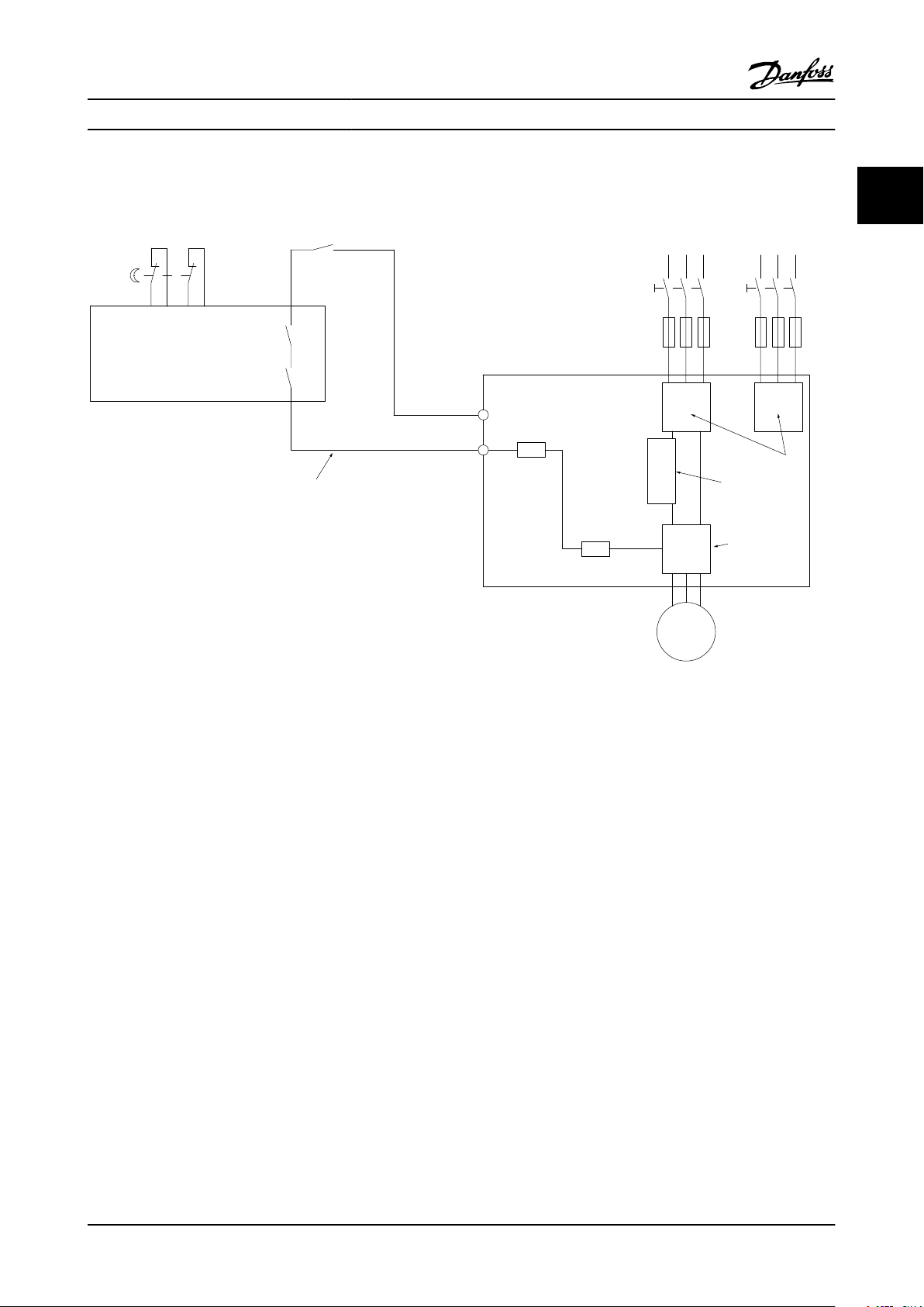
Figure 2.2 shows a Stopping Category 0 (EN 60204-1) with
safety Category 3 (EN 954-1). The circuit interrupt is caused
2-2 MG.20.Y1.22 - VLT® is a registered Danfoss trademark
Control
board
Rectier
Inverter
Safe
channel
Safety device Cat.3 (Circuit interrupt
device, possibly with release input)
Coast
Short-circuit protected cable
(if not inside installation cabinet)
Door contact
Mains
Frequency
Converter
M
37
5Vdc
12
R
1
R
2
6 phase
130BB566.10
Safety VLT AQUA 12-Pulse High Power Instruction Manual
by an opening door contact. The illustration also shows
how to connect a non-safety related hardware coast.
2 2
Figure 2.2 Essential aspects of an installation to achieve a Stopping Category 0 (EN 60204-1) with safety Category 3 (EN 954-1).
IT Line Power
2.1.8
14-50 RFI 1 can be used to disable the factory installed
A1/B1 RFI filter option. If this is done, it will reduce the RFI
performance to A2 level. For the 525–690V adjustable
frequency drives, 14-50 RFI 1 is not available as there is no
A1/B1 Factory Installed RFI Filter option.
MG.20.Y1.22 - VLT® is a registered Danfoss trademark 2-3

Safety VLT AQUA 12-Pulse High Power Instruction Manual
22
2-4 MG.20.Y1.22 - VLT® is a registered Danfoss trademark
130BB753.10
Mechanical Installation VLT AQUA 12-Pulse High Power Instruction Manual
3 Mechanical Installation
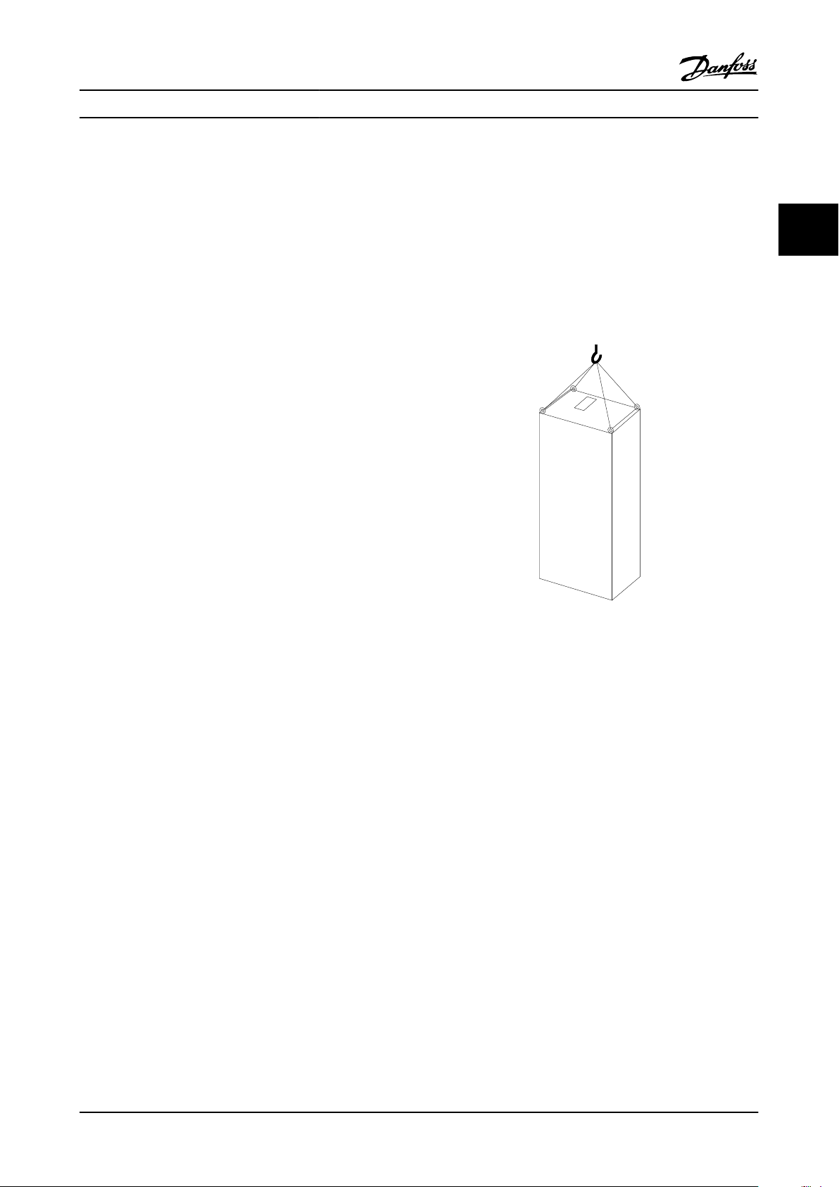
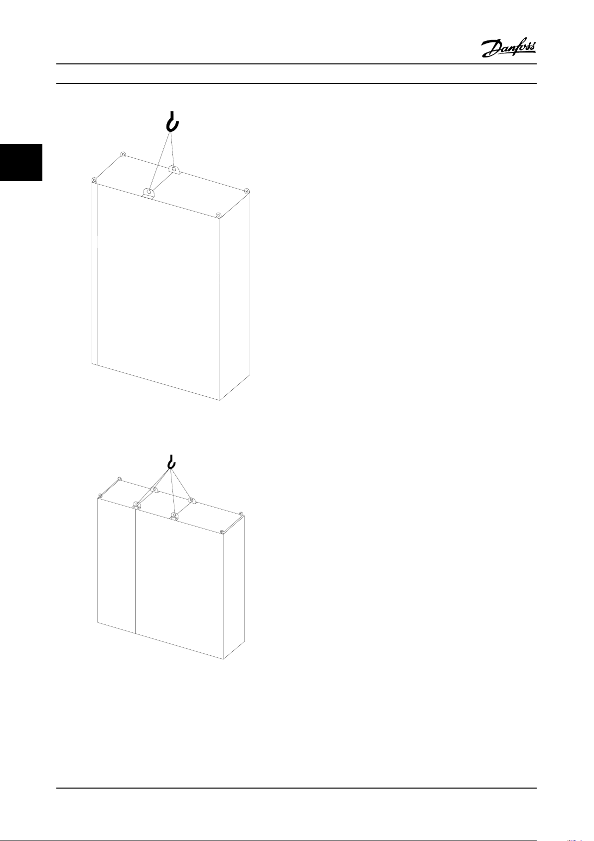
3.1.4
Lifting
3.1 Pre-installation
3.1.1 Planning the Installation Site
NOTE!
Before performing the installation, it is important to plan
the installation of the adjustable frequency drive.
Neglecting this may result in extra work during and after
installation.
Select the best possible operation site by considering the
following (see details on the following pages and in the
respective Design Guides):
Ambient operating temperature
•
Installation method
•
How to cool the unit
•
Position of the adjustable frequency drive.
•
Cable routing
•
Ensure the power source supplies the correct
•
voltage and necessary current.
Ensure that the motor current rating is within the
•
maximum current from the adjustable frequency
drive.
Ensure that the drive is properly protected per
•
local regulations.
Always lift the adjustable frequency drive using the
dedicated lifting holes. For all 4X unit size and 52 unit size
(IP00) Units, use a bar to avoid bending the lifting holes of
the adjustable frequency drive.
Figure 3.1 Recommended lifting method, Unit Size .
3
3
Receiving the Adjustable Frequency
3.1.2
Drive
When receiving the adjustable frequency drive, make sure
that the packaging is intact, and look for any damage that
might have occurred to the unit during transport. If
damage has occurred, immediately contact the shipping
company to make a damage claim.
Transportation and Unpacking
3.1.3
Before unpacking the adjustable frequency drive, it is
recommended to unload it as close as possible to the final
installation site.
Remove the box and handle the adjustable frequency drive
on the pallet, as long as possible.
MG.20.Y1.22 - VLT® is a registered Danfoss trademark 3-1
130BB688.10
130BB689.10
3
Mechanical Installation VLT AQUA 12-Pulse High Power Instruction Manual
NOTE!
Note the plinth is provided in the same packaging as the
adjustable frequency drive but is not attached during
shipment. The plinth is required to allow airflow to the
drive to provide proper cooling. The unit sizes6X should be
positioned on top of the plinth in the final installation
location. The angle from the top of the drive to the lifting
cable should be 140°F [60°C] or greater.
In addition to the drawings above a spreader bar is an
acceptable way to lift the unit sizes 6X.
Figure 3.2 Recommended lifting method, Unit Size 63
(460V, 600–900 HP, 575/600V, 900–1150 HP).
Figure 3.3 Recommended lifting method, Unit Size 64
(460V, 1000–1200 HP, 575/600V, 1250–1350 HP).
3-2 MG.20.Y1.22 - VLT® is a registered Danfoss trademark
130BB754.10
800
607
IP/21
NEMA 1
IP/54
NEMA 12
1400
m3/Hr
824
CFM
618
CFM
1050
m3/Hr
1160
CFM
1970
m3/Hr
2280
2205
1497
130BB568.10
1400
607
IP/21
NEMA 1
IP/54
NEMA 12
2100
m3/Hr
1236
CFM
927
CFM
1575
m3/Hr
1160
CFM
1970
m3/Hr
2280
2205
1497
Mechanical Installation VLT AQUA 12-Pulse High Power Instruction Manual
3.1.5 Mechanical Dimensions
3
3
Unit size 61 IP 21/54 - NEMA 1/12 Unit size 63 IP 21/54 - NEMA 1/12
All dimensions in mm
MG.20.Y1.22 - VLT® is a registered Danfoss trademark 3-3
130BB569.10
1600
607
IP/21
NEMA 1
IP/54
NEMA 12
2800
m3/Hr
1648
CFM
1236
CFM
2100
m3/Hr
2320
CFM
3940
m3/Hr
2280
2205
1497
130BB570.10
2400
607
IP/21
NEMA 1
IP/54
NEMA 12
4200
m3/Hr
2472
CFM
1854
CFM
3150
m3/Hr
2320
CFM
3940
m3/Hr
2280
2205
1497
3
Mechanical Installation VLT AQUA 12-Pulse High Power Instruction Manual
Unit size 62 IP 21/54 - NEMA 1/12 Unit size 64 IP 21/54 - NEMA 1/12
All dimensions in mm
3-4 MG.20.Y1.22 - VLT® is a registered Danfoss trademark
130BB571.10
2000
607
IP/21
NEMA 1
IP/54
NEMA 12
2800
m3/Hr
2472
CFM
1854
CFM
3150
m3/Hr
2900
CFM
4925
m3/Hr
2280
2205
1497
130BB572.10
2800
607
IP/21
NEMA 1
IP/54
NEMA 12
4200
m3/Hr
2472
CFM
1854
CFM
3150
m3/Hr
2900
CFM
4925
m3/Hr
2280
2205
1497
Mechanical Installation VLT AQUA 12-Pulse High Power Instruction Manual
3
3
Unit size 62 IP 21/54 - NEMA 1/12 Unit size 64 IP 21/54 - NEMA 1/12
All dimensions in mm
MG.20.Y1.22 - VLT® is a registered Danfoss trademark 3-5

F9
F8
130BB690.10
F11
F10
130BB691.10
F13
F12
130BB692.10
3
Mechanical Installation VLT AQUA 12-Pulse High Power Instruction Manual
Mechanical dimensions, Unit Sizes 4 and 5
Unit size 51 61 62 63 64
Heavy-duty rated power
- 160% overload torque
IP
NEMA
Shipping
dimensions
Drive
dimensions
Height
Width 38.2 in [970 mm] 61.7 in [1568 mm] 69.3 in [1760 mm]
Depth 44.49 in [1130 mm] 44.49 in [1130 mm] 44.49 in [1130 mm] 44.49 in [1130 mm] 44.49 in [1130 mm] 44.49 in [1130 mm]
Height 86.8 in [2204 mm] 86.8 in [2204 mm] 86.8 in [2204 mm] 86.8 in [2204 mm] 86.8 in [2204 mm] 86.8 in [2204 mm]
Width 31.50 in [800 mm] 55.1 in [1400 mm] 63 in [1600 mm] 86.6 in [2200 mm] 78.74 in [2000 mm] 102.4 in [2600 mm]
Depth 28.86 in [606 mm] 28.86 in [606 mm] 28.86 in [606 mm] 28.86 in [606 mm] 28.86 in [606 mm] 28.86 in [606 mm]
Max
weight
425–600 hp [315–450 kW]
(380–480 V)
535–850 hp [400–630 kW]
(525–690 V)
21, 54
Type 12
91.5 in [2324 mm] 91.5 in [2324 mm] 91.5 in [2324 mm] 91.5 in [2324 mm] 91.5 in [2324 mm] 91.5 in [2324 mm]
970 lbs [440 kg] 1446 lbs [656 kg] 1940 lbs [880 kg] 2416 lbs [1096 kg] 2253 lbs [1022 kg] 2729 lbs [1238 kg]
675–950 hp [500–710 kW]
(380–480 V)
950–1200 hp [710–900 kW]
(525–690 V)
21, 54
Type 12
100.75 in [2559
mm]
1075–1350 hp [800–1000 kW]
(380–480 V)
1350–1875 hp [1000–1400 kW]
(525–690 V)
21, 54
Type 12
85 in [2160 mm] 116.5 in [2960 mm]
3-6 MG.20.Y1.22 - VLT® is a registered Danfoss trademark
776
(30.6)
130BB531.10
130BB003.13
578
(22.8)
776
(30.6)
776
(30.6)
776
(30.6)
130BB574.10
776
(30.6)
(2x)
130BB575.10
624
(24.6)
579
(22.8)
130BB576.10
776
(30.6)
624
(24.6)
579
(22.8)
776
(30.6)
776
(30.6)
130BB577.10
Mechanical Installation VLT AQUA 12-Pulse High Power Instruction Manual
3.2 Mechanical Installation
Preparation of the mechanical installation of the adjustable
frequency drive must be done carefully to ensure proper
results and to avoid additional work during installation.
Start by taking a close look at the mechanical drawings at
Figure 3.6 Space in front of
the end of this instruction manual to become familiar with
the space demands.
3.2.1 Tools Needed
3
3
To perform the mechanical installation, the following tools
are needed:
Drill with 0.39 or 0.47 in [10 or 12 mm] drill.
•
Tape measure
•
Wrench with relevant metric sockets (7–17mm)
•
Extensions to wrench
•
Sheet metal punch for conduits or cable
•
connectors in IP 21/Nema 1 and IP 54/Nema 12
drive types.
Lifting bar to lift the unit (rod or tube max. Ø
•
25mm (1 inch), able to lift minimum 400kg
(880lbs)).
Crane or other lifting aid to place the adjustable
•
frequency drive in position
A Torx T50 tool is needed to install the Unit Size
•
51IP 21/Nema 1 and IP 54/Nema 12 drive types.
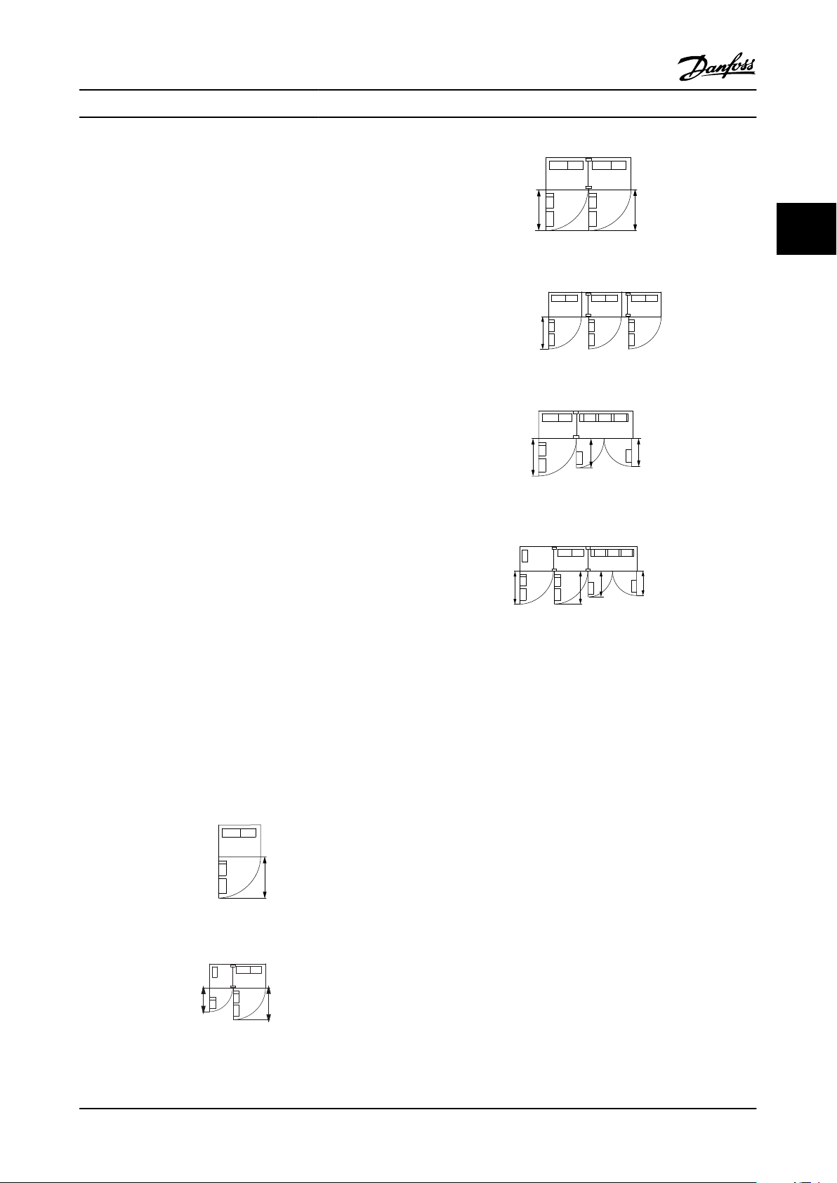
General Considerations
3.2.2
Space
Ensure proper space above and below the adjustable
frequency drive to allow airflow and cable access. In
addition, space in front of the unit must be considered to
allow the panel door to be opened.
Figure 3.7 Space in front of
Figure 3.8 Space in front of
Figure 3.9 Space in front of
Wire access
Ensure that proper cable access is present including the
necessary bending allowance.
NOTE!
All cable lugs/shoes must mount within the width of the
terminal bus bar.
Figure 3.4 Space in front of
Figure 3.5 Space in front of
MG.20.Y1.22 - VLT® is a registered Danfoss trademark 3-7
1
239.6 [ 9.43 ]
0.0 [ 0.00 ]
0.0 [ 0.00 ]
160.0 [ 6.30 ]
56.6 [ 2.23 ]
39.8 [ 1.57 ]
91.8 [ 3.61 ]
174.1 [ 6.85 ]
226.1 [ 8.90 ]
130BB534.10
R2/L12
R1/L11
91-1
91
S2/L22
S1/L21
92-1
T2/L32 93-1
92
T1/L3193
U/T1 96 V/T2 97 W/T3 98
0.0 [ 0.00 ]
57.6 [ 2.27 ]
74.0 [ 2.91 ]
100.4 [ 3.95 ]
139.4 [ 5.49 ]
172.6 [ 6.80 ]
189.0 [ 7.44 ]
199.4 [ 7.85 ]
287.6 [ 11.32 ]
304.0 [ 11.97 ]
407.3 [ 16.04 ]
464.4 [ 18.28 ]
522.3 [ 20.56 ]
524.4 [ 20.65 ]
629.7 [ 24.79 ]
637.3 [ 25.09 ]
Mechanical Installation VLT AQUA 12-Pulse High Power Instruction Manual
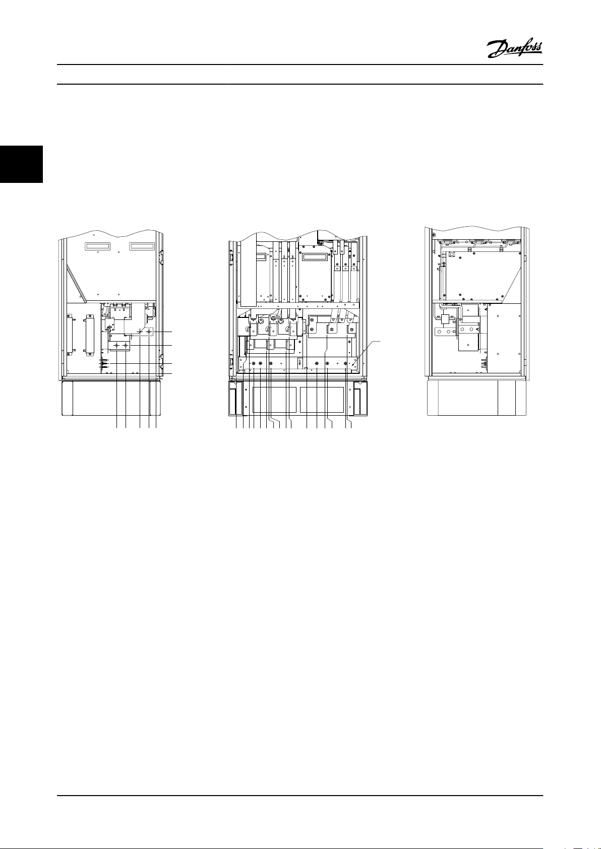
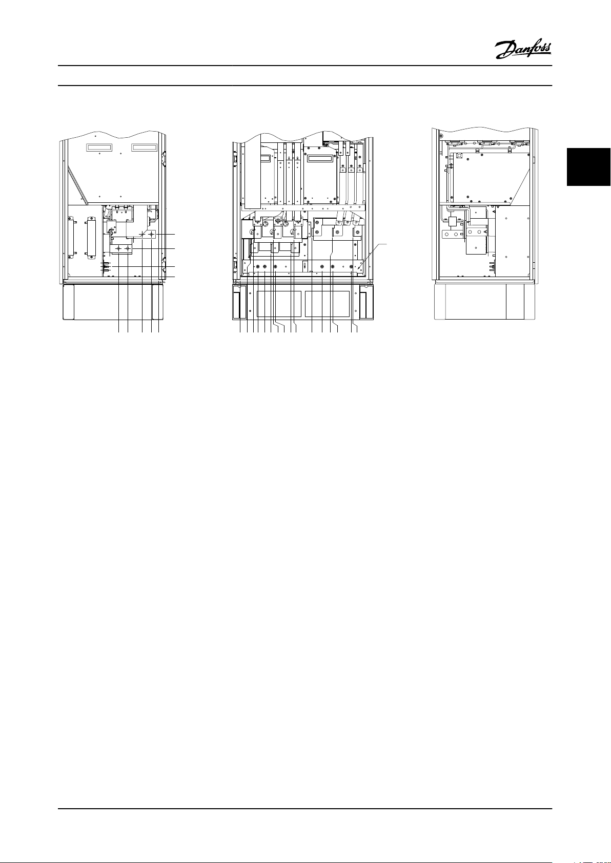
3.2.3 Terminal Locations, F8-F13
3
The F enclosures have six different sizes, 61, 62, 63, F11,
F12 and 64 The , F1061 and 62 consist of an inverter
cabinet on the right and rectifier cabinet on the left. The ,
F1163 and 64 have an additional options cabinet left of
the rectifier cabinet. The 63 is an 61 with an additional
Terminal locations - Unit Sizes 61 and 63
options cabinet. The F11 is an 62 with an additional
options cabinet. The F13 is an 62 with an additional
options cabinet.
Figure 3.10 Terminal locations - Inverter and Rectifier Cabinet - and (front, left and right side view). The connector plate is 1.65 in [42
mm] below .0 level.
1) Ground bar
3-8 MG.20.Y1.22 - VLT® is a registered Danfoss trademark
.0 [.0]
54.4[2.1]
169.4 [6.7]
284.4 [11.2]
407.3 [16.0]
522.3 [20.6]
637.3 [25.1]
287.4 [11.3]
253.1 [10.0]
.0 [.0]
.0 [.0]
339.4 [13.4]
287.4 [11.3]
.0 [.0]
339.4 [13.4]
308.3 [12.1]
465.6 [18.3]
465.6 [18.3]
198.1[7.8]
234.1 [9.2]
282.1 [11.1]
318.1 [12.5]
551.0 [21.7]
587.0 [23.1]
635.0 [25.0]
671.0 [26.4]
44.40 [1.75]
244.40 [9.62]
204.1 [8.0]
497.1 [19.6]
572.1 [22.5]
180.3 [7.1]
129.1 [5.1]
130BA849.10
2
2
1
3
3
3
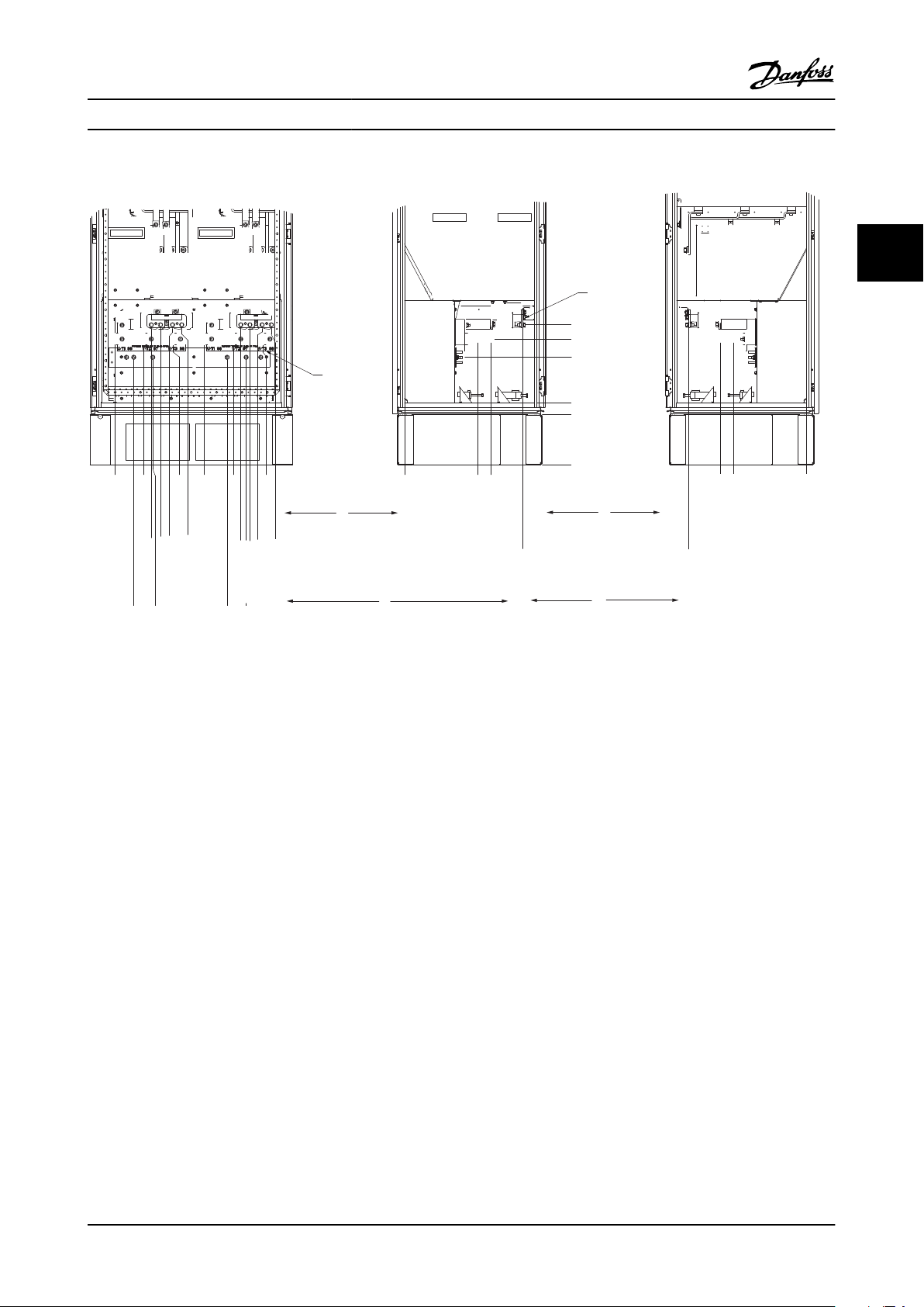
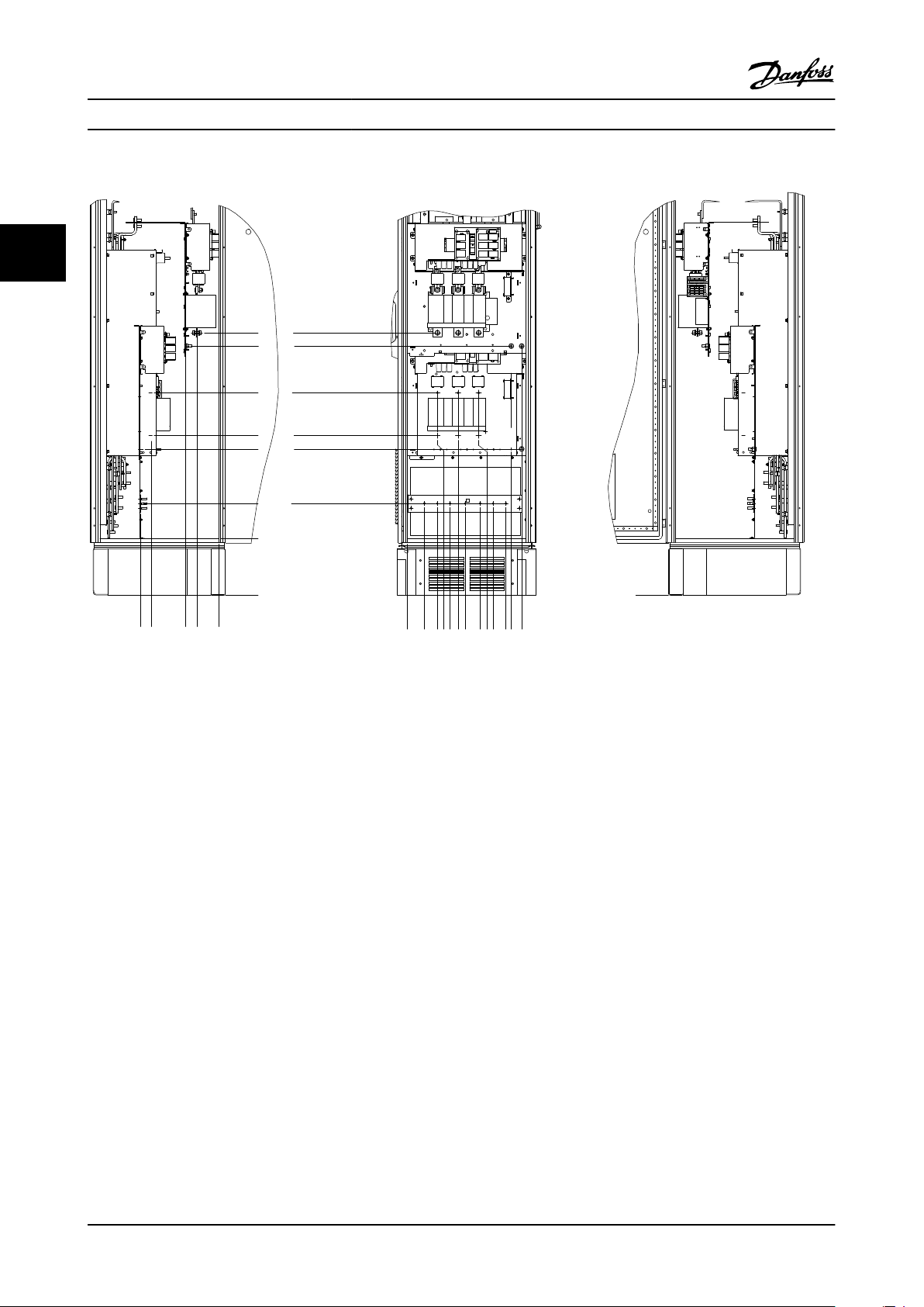
Mechanical Installation VLT AQUA 12-Pulse High Power Instruction Manual
Terminal locations - Unit Sizes 61 and 63
3
3
Figure 3.11 Terminal locations - Inverter Cabinet (front, left and right side view). The connector plate is 1.65 in [42 mm] below .0 level.
1) Ground bar
2) Motor terminals
3) Brake terminals
MG.20.Y1.22 - VLT® is a registered Danfoss trademark 3-9
287.4 [11.32]
0.0 [0.00]
339.4 [13.36]
253.1 [9.96]
0.0 [0.00]
287.4 [11.32]
0.0 [0.00]
339.4 [13.36]
465.6 [18.33]
465.6 [18.33]
308.3 [12.14]
180.3 [7.10]
210.1 [8.27]
0.0 [0.00]
66.4 [2.61]
181.4 [7.14]
296.4 [11.67]
431.0 [16.97]
546.0 [21.50]
661.0 [26.03]
795.7 [31.33]
910.7 [35.85]
1025.7 [40.38]
246.1 [9.69]
294.1 [11.58]
330.1 [13.00]
574.7 [22.63]
610.7 [24.04]
658.7 [25.93]
694.7 [27.35]
939.4 [36.98]
975.4 [38.40]
1023.4 [40.29]
1059.4 [41.71]
144.3 [5.68]
219.3 [8.63]
512.3 [20.17]
587.3 [23.12]
880.3 [34.66]
955.3 [37.61]
TERMINAL LOCATIONSFRONT VIEW
TERMINAL LOCATIONSRIGHT VIEW
TERMINAL LOCATIONSLEFT VIEW
1
2
3
2
3
130BA850.10
146x91
A
A
A
A
A
A
A
A
A
A
FASTENER TORQUE: MIO 19 Nm (14 FT -LB)
U/T1 96 V/T2 97 W/T3 98
FASTENER TORQUE: MIO 19 Nm (14 FT -LB)
U/T1 96 V/T2 97 W/T3 98
FASTENER TORQUE: MIO 19 Nm (14 FT -LB)
U/T1 96 V/T2 97 W/T3 98
3
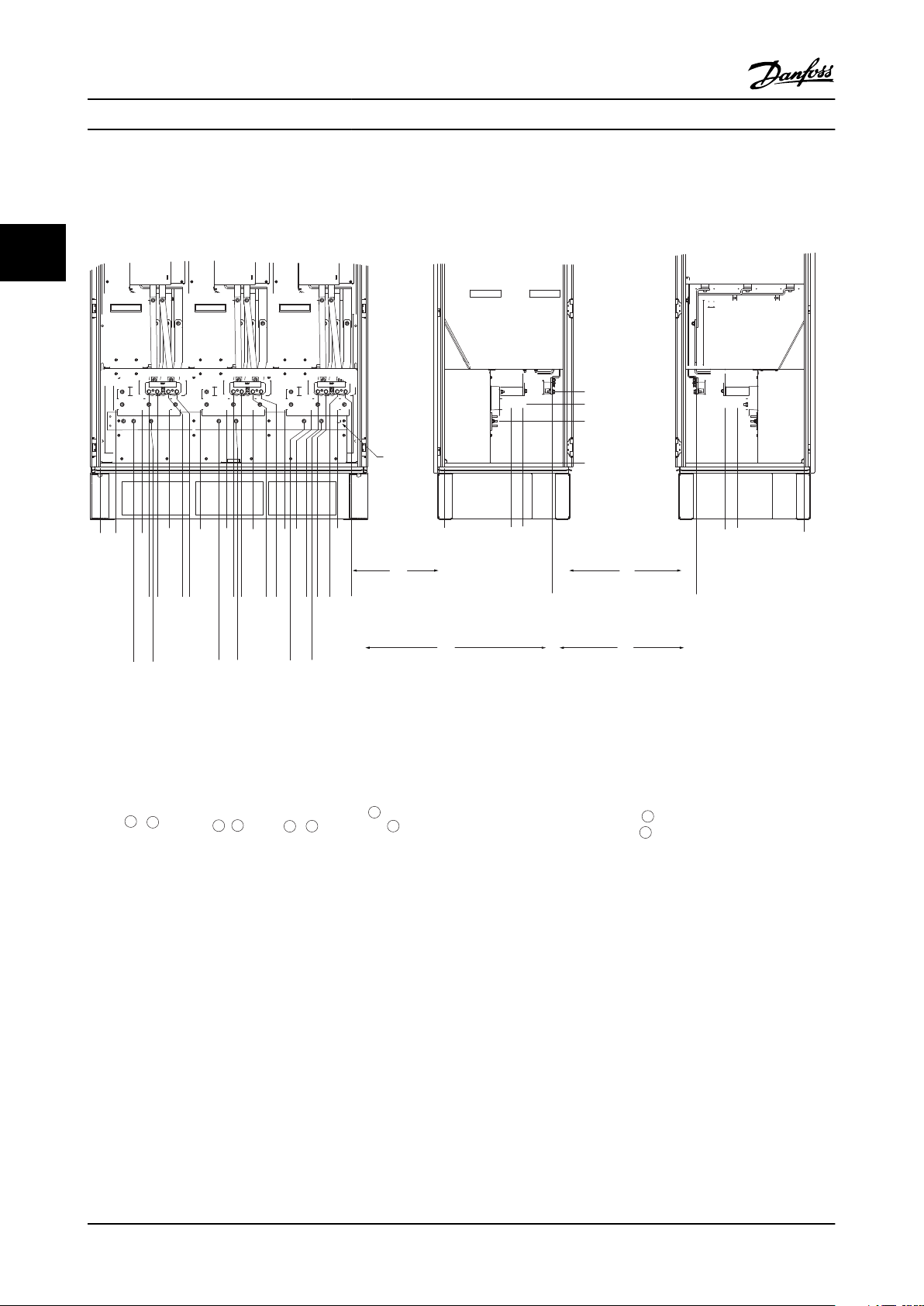
Mechanical Installation VLT AQUA 12-Pulse High Power Instruction Manual
Terminal locations - Unit Sizes 62/64
Figure 3.12 Terminal locations - Inverter Cabinet (front, left and right side view). The connector plate is 1.65 in [42 mm] below .0 level.
1) Ground bar
3-10 MG.20.Y1.22 - VLT® is a registered Danfoss trademark
1
239.6 [ 9.43 ]
0.0 [ 0.00 ]
0.0 [ 0.00 ]
160.0 [ 6.30 ]
56.6 [ 2.23 ]
39.8 [ 1.57 ]
91.8 [ 3.61 ]
174.1 [ 6.85 ]
226.1 [ 8.90 ]
130BB534.10
R2/L12
R1/L11
91-1
91
S2/L22
S1/L21
92-1
T2/L32 93-1
92
T1/L3193
U/T1 96 V/T2 97 W/T3 98
0.0 [ 0.00 ]
57.6 [ 2.27 ]
74.0 [ 2.91 ]
100.4 [ 3.95 ]
139.4 [ 5.49 ]
172.6 [ 6.80 ]
189.0 [ 7.44 ]
199.4 [ 7.85 ]
287.6 [ 11.32 ]
304.0 [ 11.97 ]
407.3 [ 16.04 ]
464.4 [ 18.28 ]
522.3 [ 20.56 ]
524.4 [ 20.65 ]
629.7 [ 24.79 ]
637.3 [ 25.09 ]
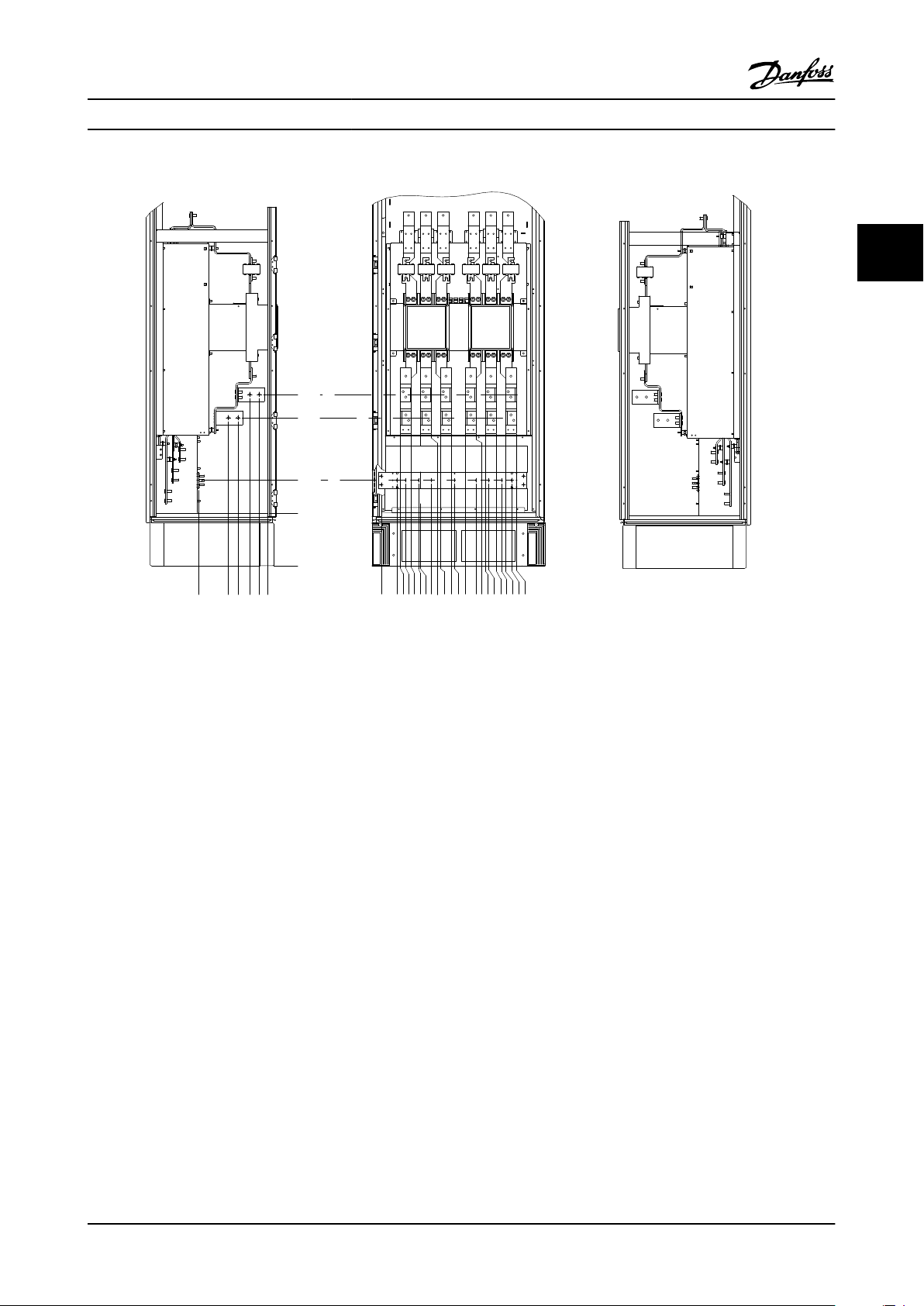
Mechanical Installation VLT AQUA 12-Pulse High Power Instruction Manual
Terminal locations - Rectifier ()
3
3
Figure 3.13 Terminal locations - Rectifier (left side, front and right side view). The connector plate is 1.65 in [42 mm] below .0 level.
1) Load share Terminal (-)
2) Ground bar
3) Load share Terminal (+)
MG.20.Y1.22 - VLT® is a registered Danfoss trademark 3-11
336.4
291.2
142.0
92.0
.0
.0
73.0
128.5
129.3
184.0
218.3
249.0
314.0
307.3
369.5
448.0
493.0
425.0
244.4
151.3
386.7
443.8
628.8
830.3
887.4
.0
130BB756.10
3
Mechanical Installation VLT AQUA 12-Pulse High Power Instruction Manual
Terminal locations - Options Cabinet Frame Size F9
Figure 3.14 Terminal locations - Options cabinet (left side, front and right side view).
3-12 MG.20.Y1.22 - VLT® is a registered Danfoss trademark
316.4
179.2
135.2
80.4
36.4
.0
244.4
.0
151.3
440.4
547.8
.0
73.0
88.1
112.0
138.9
172.0
180.7
232.0
231.5
273.3
324.1
338.9
387.8
437.0
438.6
480.4
497.0
531.2
557.0
573.0
602.3
625.8
130BB757.10
Mechanical Installation VLT AQUA 12-Pulse High Power Instruction Manual
Terminal locations - Options Cabinet Frame Size F11/F13
3
3
Figure 3.15 Terminal locations - Options cabinet (left side, front and right side view).
MG.20.Y1.22 - VLT® is a registered Danfoss trademark 3-13
90
80
70
60
50
40
30
20
10
0
(%)
Drive Derating
0 25 50 75 100 125 150 175 225
130BB190.10
200
Pressure Change
130BB073.10
3
Mechanical Installation VLT AQUA 12-Pulse High Power Instruction Manual
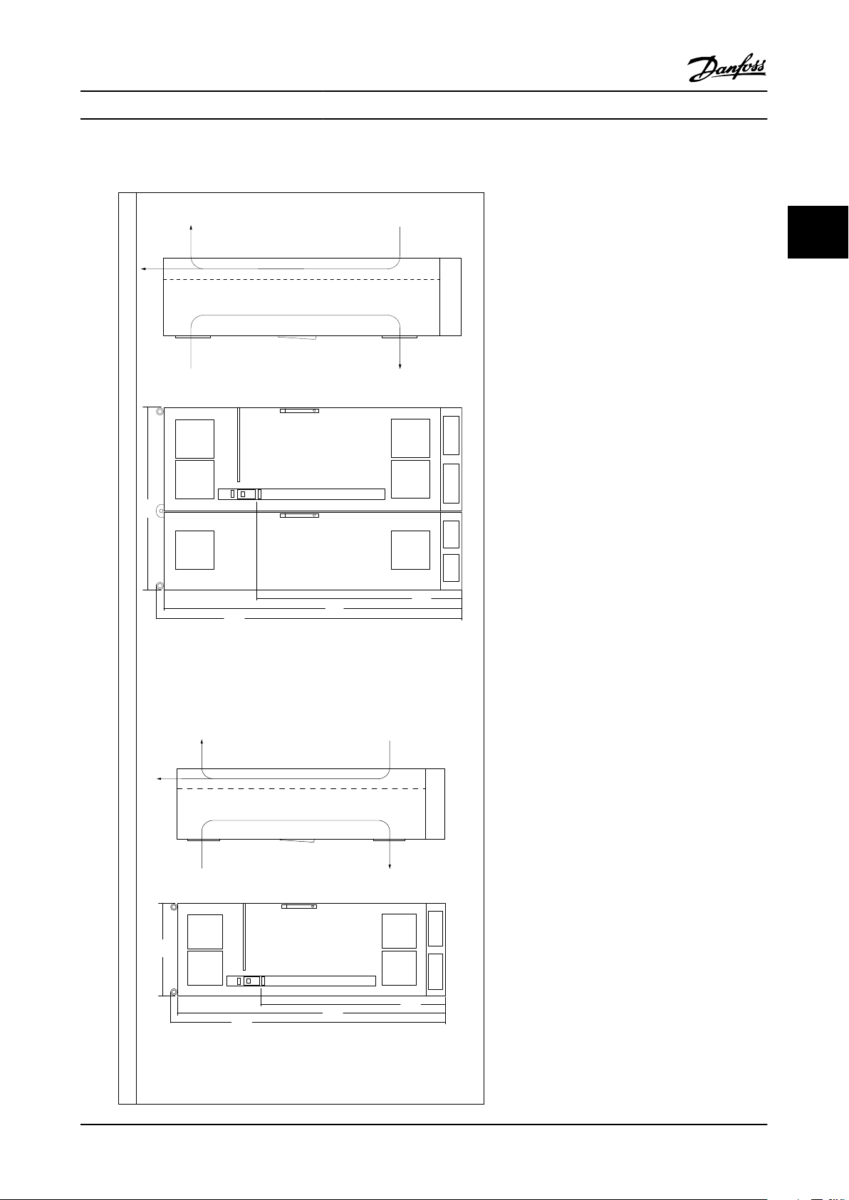
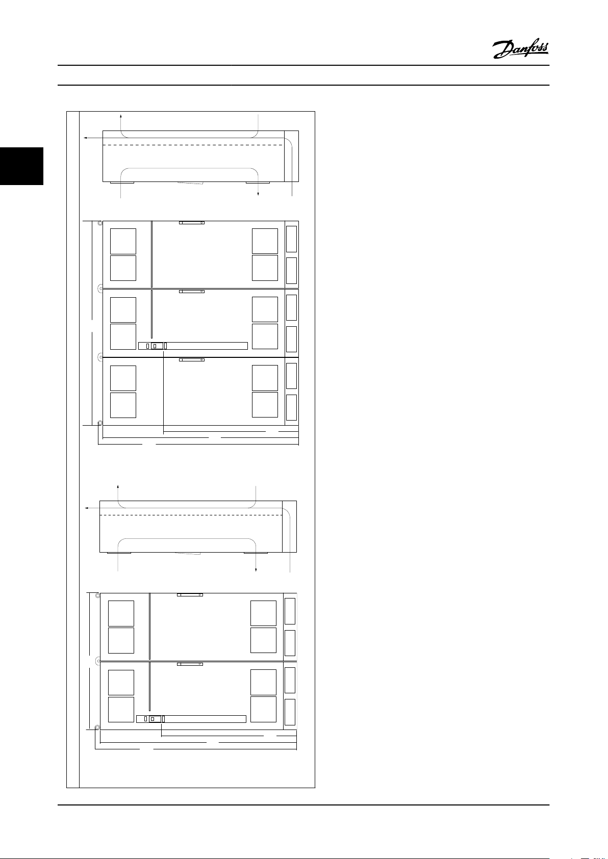
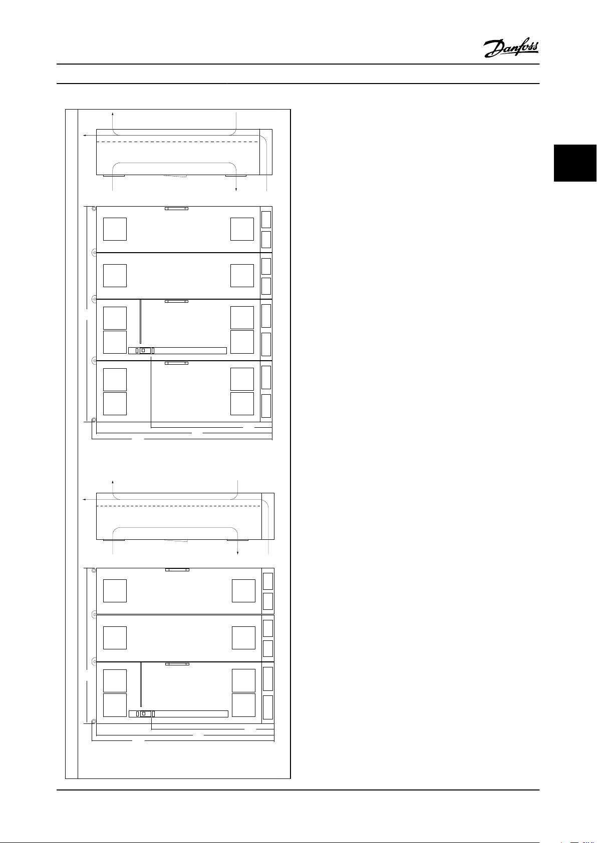
3.2.4 Cooling and Airflow
Cooling
Cooling can be obtained in different ways, by using the
cooling ducts in the bottom and the top of the unit, by
taking air in and out the back of the unit or by combining
the cooling possibilities.
Duct cooling
A dedicated option has been developed to optimize installation of drive types in Rittal TS8 Units utilizing the fan of
the adjustable frequency drive for forced air cooling of the
backchannel. Please consult GE for more details.
The air out the top of the Unit could but ducted outside a
facility so the heat loses from the backchannel are not
dissipated within the control room reducing airconditioning requirements of the facility.
Back cooling
The backchannel air can also be ventilated in and out the
back of a Rittal TS8 Unit. This offers a solution where the
backchannel could take air from outside the facility and
return the heat losses outside the facility thus reducing airconditioning requirements.
Airflow
The necessary airflow over the heatsink must be ensured.
The flow rate is shown below.
Unit Size
protection
IP21 / NEMA 1
IP54 / NEMA 12
Table 3.1 Heatsink Air Flow
* Airflow per fan. Unit Sizes 5X contain multiple fans.
Door fan(s) / Top fan
airflow
700 m3/h (412 cfm)* 985 m3/h (580 cfm)*
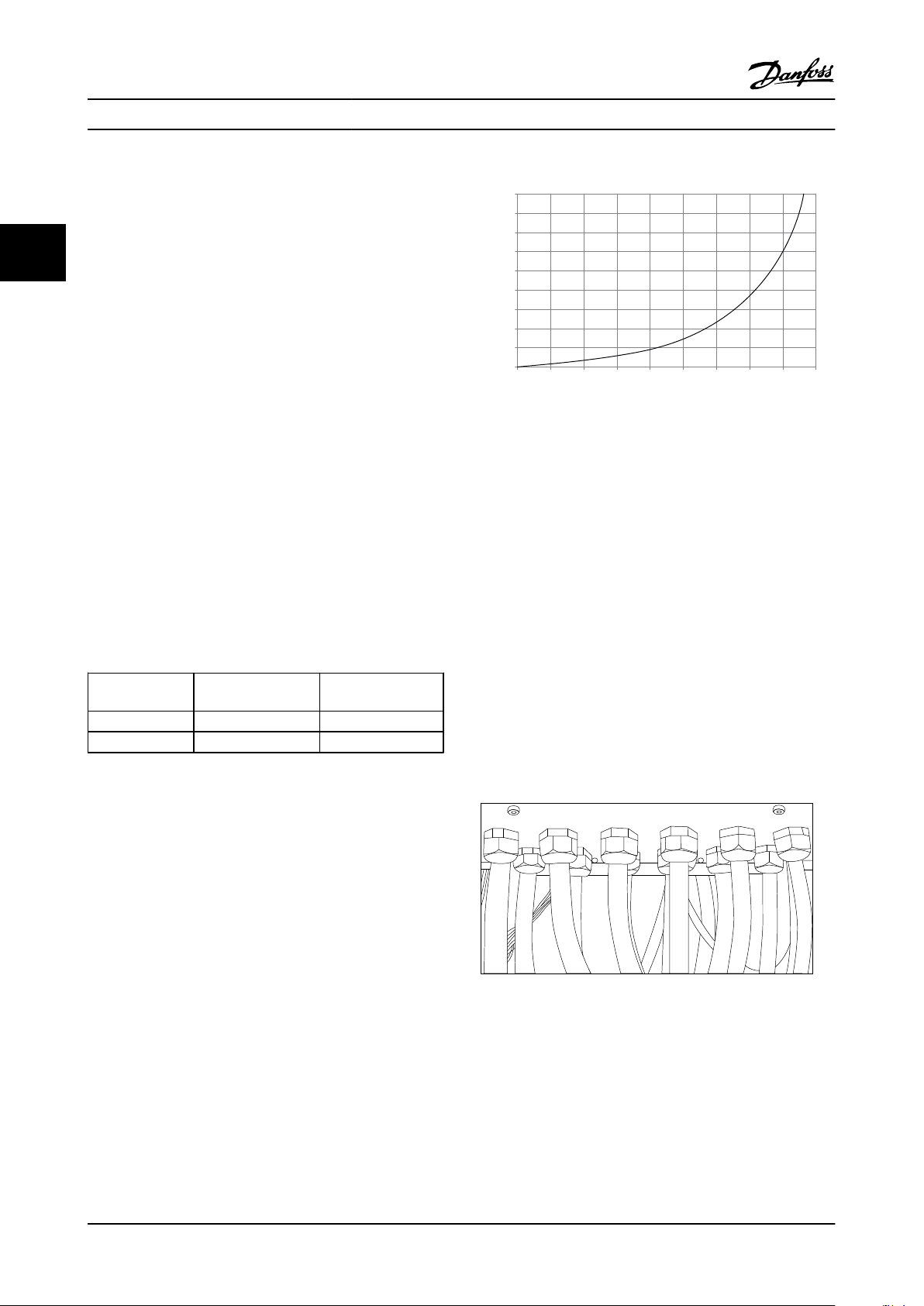
525 m3/h (309 cfm)* 985 m3/h (580 cfm)*
Heatsink fan(s)
Figure 3.16 Unit Size 61, 62, 63 and 64 Derating vs. Pressure
Change
Drive air flow: 985 m3/h (580 cfm)
Connector/Conduit Entry - IP21
3.2.5
(NEMA 1) and IP54 (NEMA12)
Cables are connected through the connector plate from
the bottom. Remove the plate and plan where to place the
entry for the connectors or conduits. Prepare holes in the
marked area on the drawing.
NOTE!
The connector plate must be fitted to the adjustable
frequency drive to ensure the specified protection degree,
as well as ensuring proper cooling of the unit. If the
connector plate is not mounted, the adjustable frequency
drive may trip on Alarm 69, Pwr. Card Temp
External ducts
If additional duct work is added externally to the Rittal
cabinet, the pressure drop in the ducting must be
calculated. Use the charts below to derate the adjustable
frequency drive according to the pressure drop.
3-14 MG.20.Y1.22 - VLT® is a registered Danfoss trademark
Figure 3.17 Example of proper installation of the connector
plate.

130BB533.10
733.0
[ 28.858 ]
258.5
[10.177 ]
199.5
[ 7.854 ]
1
593.0
[ 23.326 ]
70.0
[ 2.756 ]
535.0
21.063 ]
35.5
[ 1 ]
36.5
[ 1.437 ]
37.2
[1.47]
36.5
[1.44]
673,0
[ 26.50 ]
593,0
[ 23.35 ]
37,2
[ 1.47 ]
535,0
[ 21 . 06 ]
533,0
[ 20.98 ]
603,0
[ 23.74 ]
1336,0
[ 52.60 ]
258,5
[ 10.18 ]
199,5
[ 7.85 ]
460,0
[ 18.11 ]
1
130BB698.10
70 . 0
[ 2.756 ]
535 . 0
[ 21 . 063 ]
37 . 2
[ 1 . 466 ]
36 . 5
[ 1 . 437 ]
733 . 0
[ 28 . 858 ]
800 . 0
[ 31. 496 ]
1533 . 0
[ 60 . 354 ]
258 . 5
[ 10 . 177 ]
199 . 5
[ 7 . 854 ]
593 . 0
[ 23 . 346 ]
1
130BB694.10
Mechanical Installation VLT AQUA 12-Pulse High Power Instruction Manual
Unit Size 61
Unit Size 62
Unit Size 63
3
3
MG.20.Y1.22 - VLT® is a registered Danfoss trademark 3-15

70 . 0
[ 2.756 ]
535 . 0
[ 21 . 0631 ]
37 . 2
[ 1 . 466 ]
36 . 5
[ 1 . 437 ]
733 . 0
[ 28 . 858 ]
800 . 0
[ 31. 496 ]
258 . 5
[ 10 . 177 ]
199 . 5
[ 7 . 854 ]
870 . 7
[ 34 . 252 ]
593 . 0
[ 23 . 346 ]
593 . 0
[ 23 . 346 ]
593 . 0
[ 23 . 346 ]
1
130BB695.10
1670 . 0
[ 65 . 748 ]
1533 . 0
[ 60 . 354 ]
1600 . 0
[ 62 . 992 ]
2333 . 0
[ 91 . 850 ]
70 . 0
[ 2.756 ]
535 . 0
[ 21 . 063 ]
37 . 2
[ 1 . 466 ]
36 . 5
[ 1 . 437 ]
733 . 0
[ 28 . 858 ]
800 . 0
[ 32 ]
1933 . 0
[ 76 ]
258 . 5
[ 10 . 177 ]
199 . 5
[ 7 . 854 ]
994 . 3
[ 39 . 146 ]
857 . 7
[ 33 . 768 ]
593 . 0
[ 23 . 346 ]
1
130BB696.10
70 . 0
[ 2.756 ]
535 . 0
[ 21 . 0631 ]
37 . 2
[ 1 . 466 ]
36 . 5
[ 1 . 437 ]
733 . 0
[ 28 . 858 ]
800 . 0
[ 31. 496 ]
258 . 5
[ 10 . 177 ]
199 . 5
[ 7 . 854 ]
994 . 3
[ 39 . 146 ]
870 . 7
[ 34 . 252 ]
593 . 0
[ 23 . 346 ]
593 . 0
[ 23 . 346 ]
1
130BB697.10
1657 . 7
[ 65 . 2641 ]
1533 . 0
[ 60 . 354 ]
1600 . 0
[ 62 . 992 ]
2733 . 0
[ 107 . 598 ]
3
Mechanical Installation VLT AQUA 12-Pulse High Power Instruction Manual
Unit Size 64
Unit Size 64
Unit Size 64
: Cable entries viewed from the bottom of the adjustable frequency drive - 1) Place conduits in marked areas.
3-16 MG.20.Y1.22 - VLT® is a registered Danfoss trademark

Mechanical Installation VLT AQUA 12-Pulse High Power Instruction Manual
3.3 Frame size F Panel Options
3
3
MG.20.Y1.22 - VLT® is a registered Danfoss trademark 3-17

3
Mechanical Installation VLT AQUA 12-Pulse High Power Instruction Manual
3-18 MG.20.Y1.22 - VLT® is a registered Danfoss trademark

6 Phase
power
input
130BB693.10
91-1 (L1-1)
92-1 (L2-1)
93-1 (L3-1)
91-2
92-2
93-2
95 PE
(L2-2)
(L1-2)
(L3-2)
How to Install VLT AQUA 12-Pulse High Power Instruction Manual
4 How to Install
4.1 Electrical Installation
4.1.1 Power Connections
Cabling and Fusing
NOTE!
Cables General
All cabling must comply with national and local
regulations on cable cross-sections and ambient
temperature. UL applications require 167°F [75°C] copper
conductors. 167°F [75°C] and 194°F [90°C] copper
conductors are thermally acceptable for the adjustable
frequency drive to use in non-UL applications.
The power cable connections are situated as shown below.
Dimensioning of cable cross-section must be done in
accordance with the current ratings and local legislation.
See7.1 General Specifications for details.
For protection please see fuse in the tables of the fuse
section. Always ensure that proper fusing is done
according to local regulations.
4 4
NOTE!
Use a shielded/armored motor cable to comply with EMC
emission specifications. For more information, see EMC
specifications in the /FC 300Design Guide.
See 7.1 General Specifications for correct dimensioning of
motor cable cross-section and length.
MG.20.Y1.22 - VLT® is a registered Danfoss trademark 4-1

* F10/F11/F12/F13 Only
91-1
92-1
93-1
91-2
92-2
93-2
S1
T1
R1
S2
T2
R2
95
Rectifier 1
Rectifier 2
Inverter1
F8/F9
Inverter2
F10/F11
Inverter3
F12/F13
130BB758.10
91-1
92-1
93-1
91-2
92-2
93-2
S1
T1
R1
S2
T2
R2
95
Rectifier 1
Rectifier 2
Inverter1
F8/F9
Inverter2
F10/F11
Inverter3
F12/F13
91-1
92-1
93-1
91-2
92-2
93-2
95
Rectifier 1
Rectifier 2
Inverter1
Inverter2
F10/F11
Inverter3
F12/F13
A
B
C
How to Install VLT AQUA 12-Pulse High Power Instruction Manual
44
Figure 4.1
A) 6-Pulse Connection
B) Modified 6-Pulse Connection
C) 12-Pulse Connection
Notes:
1), 2), 3)
3), 5)
2), 3), 4)
1) Parallel connection shown. A single 3-phase cable may be used with sufficient carrying capability. Shorting busbars must
be installed.
2) 6-pulse connection eliminates the harmonics reduction benefits of the 12-pulse rectifier.
3) Suitable for IT and TN AC line input connections.
4) In the unlikely event that one of the 6-pulse modular rectifiers becomes inoperable, it is possible to operate the drive at
reduced load with a single 6-pulse rectifier. Contact factory for reconnection details.
5) No paralleling of line power cabling is shown here.
4-2 MG.20.Y1.22 - VLT® is a registered Danfoss trademark

U V W
175ZA114.10
VU W
96 97 98
96 97 98
How to Install VLT AQUA 12-Pulse High Power Instruction Manual
Shielding of cables:
Avoid installation with twisted shield ends (pigtails). They
spoil the shielding effect at higher frequencies. If it is
necessary to break the shield to install a motor isolator or
motor contactor, the shield must be continued at the
lowest possible HF impedance.
Connect the motor cable shield to both the de-coupling
plate of the adjustable frequency drive and to the metal
housing of the motor.
Make the shield connections with the largest possible
surface area (cable clamp). This is done by using the
Term. no. 96 97 98 99
U V W
U1 V1 W1
W2 U2 V2 6 wires out of motor
U1 V1 W1
1)
Protected Ground Connection
supplied installation devices within the adjustable
frequency drive.
Cable-length and cross-section:
The adjustable frequency drive has been EMC tested with
a given length of cable. Keep the motor cable as short as
possible to reduce the noise level and leakage currents.
Switching frequency:
When adjustable frequency drives are used together with
4 4
sine-wave filters to reduce the acoustic noise from a
motor, the switching frequency must be set according to
the instructions in 14-01 Switching Frequency.
1)
PE
PE
PE
Motor voltage 0–100% of AC line voltage.
3 wires out of motor
Delta-connected
1)
1)
Star-connected U2, V2, W2
U2, V2 and W2 to be interconnected separately.
MG.20.Y1.22 - VLT® is a registered Danfoss trademark 4-3

130BB532.10
9
8
7
6
5
4
3
2
1
10
How to Install VLT AQUA 12-Pulse High Power Instruction Manual
44
Figure 4.2 Rectifier and Inverter Cabinet, unit sizes 61, 62, 63 and 64.
12-pulse rectifier module 5) Motor connection
1)
2) Ground PE Terminals U V W
3) Line / Fuses T1 T2 T3
R1 S1 T1 96 97 98
L1-1 L2-1 L3-1 6) Brake Terminals
91-1 92-1 93-1 -R +R
4) Line / Fuses 81 82
R2 S2 T2 7) Inverter Module
L2-1 L2-2 L3-2 8) SCR Enable / Disable
91-2 92-2 93-2 9) Relay 1 Relay 2
01 02 03 04 05 06
10) Auxillary Fan
104 106
4-4 MG.20.Y1.22 - VLT® is a registered Danfoss trademark

1
2
130BB755.10
3
4
How to Install VLT AQUA 12-Pulse High Power Instruction Manual
4 4
Figure 4.3 Rectifier Cabinet, unit sizes 61, 62, 63 and 64.
12-pulse rectifier module 4) Line
1)
2) AUX Fan R1 S1 T1 R2 S2 T2
100 101 102 103 L1-1 L2-1 L3-1 L1-2 L2-2 L3-2
L1 L2 L1 L2 5) DC Bus Connections for Common DC Bus
3) Line Fuses F10/F12 (6 pieces) DC+ DC-
6) DC Bus Connections for Common DC Bus
DC+ DC-
MG.20.Y1.22 - VLT® is a registered Danfoss trademark 4-5

3
5
6
4, 8, 9
21
7
130BA861.12
U/T1 96
FASTENER TORQUE: M10 19 Nm (14 FT-LB)FASTENER TORQUE: M10 19 Nm (14 FT-LB)
V/T2 97
W/T3 98 U/T1 96
V/T2 97
W/T3 98
FASTENER TORQUE:
-R 81 +R 82
M8 9.6 NM (7 FT-LB) FASTENER TORQUE:
-R 81 +R 82
M8 9.6 NM (7 FT-LB)
How to Install VLT AQUA 12-Pulse High Power Instruction Manual
44
Figure 4.4 Inverter Cabinet, unit sizes 61 and 63.
External Temperature Monitoring 6) Motor
1)
2) AUX Relay U V W
01 02 03 96 97 98
04 05 06 T1 T2 T3
3) NAMUR 7) NAMUR Fuse. See fuse tables for part numbers
4) AUX Fan 8) Fan Fuses. See fuse tables for part numbers
100 101 102 103 9) SMPS Fuses. See fuse tables for part numbers
L1 L2 L1 L2
5) Brake
-R +R
81 82
4-6 MG.20.Y1.22 - VLT® is a registered Danfoss trademark

3
5
U/T1 96
FASTENER TORQUE: M10 19 Nm (14 FT-LB)
V/T2 97 W/T3 98 U/T1 96
FASTENER TORQUE: M10 19 Nm (14 FT-LB)
V/T2 97 W/T3 98 U/T1 96
FASTENER TORQUE: M10 19 Nm (14 FT-LB)
V/T2 97 W/T3 98
6
4, 8, 9
2
1
7
130BA862.12
How to Install VLT AQUA 12-Pulse High Power Instruction Manual
4 4
Figure 4.5 Inverter Cabinet, unit sizes 62 and 64
External Temperature Monitoring 6) Motor
1)
2) AUX Relay U V W
01 02 03 96 97 98
04 05 06 T1 T2 T3
3) NAMUR 7) NAMUR Fuse. See fuse tables for part numbers
4) AUX Fan 8) Fan Fuses. See fuse tables for part numbers
100 101 102 103 9) SMPS Fuses. See fuse tables for part numbers
L1 L2 L1 L2
5) Brake
-R +R
81 82
MG.20.Y1.22 - VLT® is a registered Danfoss trademark 4-7

R/L1 91 S/L2 92 T/L3 93
R/L1 91 S/L2 92 T/L3 93
CFD30J3
130BB699.10
3
6
5
2
1
4
How to Install VLT AQUA 12-Pulse High Power Instruction Manual
44
Figure 4.6 Options Cabinet, frame size F9
4-8 MG.20.Y1.22 - VLT® is a registered Danfoss trademark

176FA247.12
Nm/in-lbs
-DC 88
+DC 89
R/L1 91
S/L2 92
T/L3 93
U/T1 96
V/T2 97
W/T3
How to Install VLT AQUA 12-Pulse High Power Instruction Manual
4.1.2 Grounding
The following basic issues need to be considered when
installing an adjustable frequency drive, so as to obtain
electromagnetic compatibility (EMC).
Safety grounding: Please note that the adjustable
•
frequency drive has a high leakage current and
must be grounded appropriately for safety
reasons. Always follow local safety regulations.
High-frequency grounding: Keep the ground wire
•
connections as short as possible.
Connect the different ground systems at the lowest
possible conductor impedance. The lowest possible
conductor impedance is obtained by keeping the
conductor as short as possible and by using the greatest
possible surface area.
The metal cabinets of the different devices are mounted
on the cabinet rear plate using the lowest possible HF
impedance. This prevents having different HF voltages for
the individual devices and prevents the risk of radio
interference currents running in connection cables that
may be used between the devices, as radio interference is
reduced.
In order to obtain a low HF impedance, use the fastening
bolts of the devices as HF connections to the rear plate. It
is necessary to remove insulating paint and the like from
the fastening points.
For further reference, see IEC 364-3. In case optimum EMC
performance is needed, parallel motors are connected or
the motor cable length is above 82 ft [25 m], it is
recommended to set 14-50 RFI 1 to [ON].
In OFF, the internal RFI capacities (filter capacitors)
between the chassis and the intermediate circuit are cut
off to avoid damage to the intermediate circuit and to
reduce the ground capacity currents (according to IEC
61800-3).
It is important to use isolation monitors that are capable
for use together with power electronics (IEC 61557-8).
4.1.5 Torque
When tightening all electrical connections it is important
to tighten with the correct torque. Too low or too high
torque results in a poor electrical connection. Use a torque
wrench to ensure correct torque.
4 4
Extra Protection (RCD)
4.1.3
ELCB relays, multiple protective grounding or grounding
can be used as extra protection, provided that local safety
regulations are complied with.
In the case of a ground fault, a DC component may
develop in the fault current.
If ELCB relays are used, local regulations must be observed.
Relays must be suitable for protection of 3-phase
equipment with a bridge rectifier and for a brief discharge
on power-up.
See also the section Special Conditions in the Design Guide.
4.1.4
Drives with Factory-installed A1/B1
RFI Filter Option:
Line power supply isolated from ground
If the adjustable frequency drive is supplied from an
isolated line power source ( IT line power, floating delta
and grounded delta) or TT/TN-S line power with grounded
leg, the RFI switch is recommended to be turned off (OFF)
via 14-50 RFI 1 on the drive and 14-50 RFI 1 on the filter.
Figure 4.7 Always use a torque wrench to tighten the bolts.
Shielded Cables
4.1.6
NOTE!
Danfoss recommends to use shielded cables between the
LCL filter and the AFE unit. Unshielded cables can be used
between transformer and LCL filter input side.
It is important that shielded and armored cables are
connected in a proper way to ensure the high EMC
immunity and low emissions.
MG.20.Y1.22 - VLT® is a registered Danfoss trademark 4-9

96 97
U V
96 97 98
U V W
98
W
130HA036.10
How to Install VLT AQUA 12-Pulse High Power Instruction Manual
The connection can be made using either cable
connectors or clamps:
EMC cable connectors: generally available cable
•
connectors can be used to ensure an optimum
EMC connection.
EMC cable clamp: Clamps allowing for easy
•
connection are supplied with the adjustable
44
frequency drive.
4.1.7 Motor Cable
The motor must be connected to terminals U/T1/96, V/
T2/97, W/T3/98. Ground to terminal 99. All types of threephase asynchronous standard motors can be used with an
adjustable frequency drive unit. The factory setting is for
clockwise rotation with the adjustable frequency drive
output connected as follows:
Terminal No. Function
96, 97, 98, 99 Line power U/T1, V/T2, W/T3
Ground
•
•
•
Unit Size 6X Requirements
requirements: The cables are required to be equal length
within 10% between the inverter module terminals and the
first common point of a phase. The recommended
common point is the motor terminals.
Unit Size 61/63 requirements: Motor phase cable quantities
must be multiples of 2, resulting in 2, 4, 6, or 8 (1 cable is
not allowed) to obtain equal amount of wires attached to
both inverter module terminals. The cables are required to
be equal length within 10% between the inverter module
terminals and the first common point of a phase. The
recommended common point is the motor terminals.
Unit Size 62 and 64 requirements: Motor phase cable
quantities must be multiples of 3, resulting in 3, 6, 9, or 12
(1 or 2 cables are not allowed) to obtain equal amount of
wires attached to each inverter module terminal. The wires
are required to be equal length within 10% between the
inverter module terminals and the first common point of a
phase. The recommended common point is the motor
terminals.
Terminal U/T1/96 connected to U-phase
Terminal V/T2/97 connected to V-phase
Terminal W/T3/98 connected to W-phase
The direction of rotation can be changed by switching two
phases in the motor cable or by changing the setting of
4-10 Motor Speed Direction and reversing.
Output junction box requirements: The length, a minimum
of 8 ft [2.5 m], and quantity of cables must be equal from
each inverter module to the common terminal in the
junction box.
4.1.8 Shielding against Electrical Noise
Before mounting the line power cable, mount the EMC
metal cover to ensure best EMC performance.
NOTE!
The EMC metal cover is only included in units with factoryinstalled A1/B1 RFI Filter option..
4-10 MG.20.Y1.22 - VLT® is a registered Danfoss trademark

175ZT975.10
How to Install VLT AQUA 12-Pulse High Power Instruction Manual
be used for protection. In UL applications, this should be a
LittleFuse KLK-5 or equivalent.
Figure 4.8 Mount the EMC shield.
4.1.9 AC line input connections
Line power must be connected to terminals 91-1, 92-1,
93-1, 91-2, 92-2 and 93-2 (see Table 4.1). Ground is
connected to the terminal to the right of terminal 93.
Terminal No. Function
91-1, 92-1, 93-1 Line power R1/L1-1, S1/L2-1, T1/
L3-1
91-2, 92-2, 93-2 Line power R2/L1-2, S2/L2-2, T2/
L3-2
94 Ground
4 4
NOTE!
Check the nameplate to ensure that the AC line voltage of
the adjustable frequency drive matches the power supply
of your plant.
Ensure that the power supply can supply the necessary
current to the adjustable frequency drive.
4.1.10
If the adjustable frequency drive is supplied by DC or if the
fan must run independently of the power supply, an
external power supply can be applied. The connection is
made on the power card.
Terminal No.
100, 101
102, 103
The connector located on the power card provides the AC
line voltage connection for the cooling fans. The fans are
factory-equipped to be supplied from a common AC line
(jumpers between 100-102 and 101-103). If an external
supply is needed, the jumpers are removed and the supply
is connected to terminals 100 and 101. A 5A fuse should
External Fan Supply
Function
Auxiliary supply S, T
Internal supply S, T
MG.20.Y1.22 - VLT® is a registered Danfoss trademark 4-11

How to Install VLT AQUA 12-Pulse High Power Instruction Manual
4.1.11 Fuses
Branch circuit protection:
In order to protect the installation against electrical and
fire hazard, all branch circuits in an installation, switch
gear, machines, etc., must be short-circuited and
overcurrent protected according to national/international
44
regulations.
Short-circuit protection:
The adjustable frequency drive must be protected against
short-circuit to avoid electrical or fire hazard. Danfoss
recommends using the fuses mentioned below to protect
service personnel and equipment in case of an internal
failure in the drive. The adjustable frequency drive
provides full short-circuit protection in case of a short-
Overcurrent protection
Provide overload protection to avoid fire hazard due to
overheating of the cables in the installation. Fuses or
circuit breakers can be used to provide the overcurrent
protection in the installation. Overcurrent protection must
always be carried out according to national regulations.
UL compliance
The fuses below are suitable for use on a circuit capable of
delivering 100,000 Arms (symmetrical), 240 V, or 480 V, or
600 V depending on the drive voltage rating. With the
proper fusing, the drive Short Circuit Current Rating (SCCR)
is 100,000 Arms.
circuit on the motor output.
Power size Frame Rating Bussmann
Size Voltage (UL) Amperes P/N P/N 400V 460V
P315T5 F8/F9 700 700 170M4017 176F9179 25 19
P355T5 F8/F9 700 700 170M4017 176F9179 30 22
P400T5 F8/F9 700 700 170M4017 176F9179 38 29
P450T5 F8/F9 700 700 170M4017 176F9179 3500 2800
P500T5 F10/F11 700 900 170M6013 176F9180 3940 4925
P560T5 F10/F11 700 900 170M6013 176F9180 2625 2100
P630T5 F10/F11 700 900 170M6013 176F9180 3940 4925
P710T5 F10/F11 700 1500 170M6018 176F9181 45 34
P800T5 F12/F13 700 1500 170M6018 176F9181 60 45
P1M0T5 F12/F13 700 1500 170M6018 176F9181 83 63
Spare
Bussmann
Est. Fuse Power Loss [W]
Table 4.1 Line Fuses, 380–500V
Power size Frame Rating Bussmann
Size Voltage (UL) Amperes P/N P/N 600V 690V
P450T7 F8/F9 700 630 170M4016 176F9179 13 10
P500T7 F8/F9 700 630 170M4016 176F9179 17 13
P560T7 F8/F9 700 630 170M4016 176F9179 22 16
P630T7 F8/F9 700 630 170M4016 176F9179 24 18
P710T7 F10/F11 700 900 170M6013 176F9180 26 20
P800T7 F10/F11 700 900 170M6013 176F9180 35 27
P900T7 F10/F11 700 900 170M6013 176F9180 44 33
P1M0T7 F12/F13 700 1500 170M6018 176F9181 26 20
P1M2T7 F12/F13 700 1500 170M6018 176F9181 37 28
P1M4T7 F12/F13 700 1500 170M6018 176F9181 47 36
Table 4.2 Line Fuses, 525–690V
Spare
Bussmann
Est. Fuse Power Loss [W]
4-12 MG.20.Y1.22 - VLT® is a registered Danfoss trademark

How to Install VLT AQUA 12-Pulse High Power Instruction Manual
AF-650 GP Bussmann PN* Rating Siba
600 HP 170M8611 1100 A, 1000 V 20 781 32.1000
650 HP 170M8611 1100 A, 1000 V 20 781 32.1000
750 HP 170M6467 1400 A, 700 V 20 681 32.1400
900 HP 170M6467 1400 A, 700 V 20 681 32.1400
1000 HP 170M8611 1100 A, 1000 V 20 781 32.1000
1200 HP 170M6467 1400 A, 700 V 20 681 32.1400
Table 4.3 Inverter Module DC Link Fuses, 380–480V
AF-650 GP Bussmann PN* Rating Siba
900 HP 170M8611 1100 A, 1000 V 20 781 32. 1000
1000 HP 170M8611 1100 A, 1000 V 20 781 32. 1000
1200 HP 170M8611 1100 A, 1000 V 20 781 32. 1000
1250 HP 170M8611 1100 A, 1000 V 20 781 32. 1000
1350 HP 170M8611 1100 A, 1000 V 20 781 32. 1000
170M8611 1100A, 1000V 20 781 32.1000
Table 4.4 525–690V
*170M fuses from Bussmann shown use the -/80 visual indicator; TN/80 Type T, -/110 or TN/110 Type T indicator fuses of the same size
and amperage may be substituted for external use.
4 4
Supplementary fuses
Size/Type Bussmann PN* Rating Alternative Fuses
2.5–4.0 A Fuse , 380– V LPJ-6 SP or SPI 6 A, 600 V Any listed Class J Dual
750–1350 HP, 525–690 V LPJ-10 SP or SPI 10 A, 600 V Any listed Class J Dual
4.0–6.3 A Fuse 600–1200HP, 380–480 V LPJ-10 SP or SPI 10 A, 600 V Any listed Class J Dual
750–1350 HP, 525–690 V LPJ-15 SP or SPI 15 A, 600 V Any listed Class J Dual
6.3–10 A Fuse 600–1200HP, 380–480 V LPJ-15 SP or SPI 15 A, 600 V Any listed Class J Dual
750–1350 HP, 525–690 V LPJ-20 SP or SPI 20 A, 600 V Any listed Class J Dual
10–16 A Fuse 600–1200HP, 380–480 V LPJ-25 SP or SPI 25 A, 600 V Any listed Class J Dual
750–1350 HP, 525–690 V LPJ-20 SP or SPI 20 A, 600 V Any listed Class J Dual
Table 4.5 Manual Motor Controller Fuses
Unit Sizes Bussmann PN* Rating
KTK-4 4 A, 600V
Unit Sizes
F8-F13 LPJ-30 SP or SPI 30 A, 600 V Any listed Class J
Bussmann PN* Rating Alternative Fuses
Table 4.6 SMPS Fuse
Size/Type Bussmann PN* LittelFuse Rating
400–1200HP,
380–480 V
650–1350HP,
525–690 V
KLK-15 15A, 600V
KLK-15 15A, 600V
Table 4.7 Fan Fuses
Table 4.8 30 A Fuse Protected Terminal Fuse
Unit Sizes Bussmann PN* Rating Alternative Fuses
F8-F13 LPJ-6 SP or SPI 6 A, 600 V Any listed Class J
Table 4.9 Control Transformer Fuse
Element, Time Delay, 6 A
Element, Time Delay, 10 A
Element, Time Delay, 10 A
Element, Time Delay, 15 A
Element, Time Delay, 15 A
Element, Time Delay, 20 A
Element, Time Delay, 25 A
Element, Time Delay, 20 A
Dual Element,
Time Delay, 30 A
Dual Element,
Time Delay, 6 A
MG.20.Y1.22 - VLT® is a registered Danfoss trademark 4-13

How to Install VLT AQUA 12-Pulse High Power Instruction Manual
Unit Sizes Bussmann PN* Rating
F8-F13 GMC-800MA 800mA, 250V
Table 4.10 NAMUR Fuse
4.1.12 Motor Insulation
44
For motor cable lengths ≤ than the maximum cable length
listed in the General Specifications tables, the following
motor insulation ratings are recommended because the
peak voltage can be up to twice the DC link voltage, 2.8
times the AC line voltage due to transmission line effects
in the motor cable. If a motor has lower insulation rating,
it is recommended to use a du/dt or sine-wave filter.
Nominal AC Line Voltage Motor Insulation
UN ≤ 420 V
420V < UN ≤ 500 V Reinforced ULL = 1600V
500V < UN ≤ 600 V Reinforced ULL = 1800V
600V < UN ≤ 690 V Reinforced ULL = 2000V
Standard ULL = 1300V
4.1.13 Motor Bearing Currents
All motors installed with 425 hp [315 kW] or higher power
drives should have NDE (Non-Drive End) insulated bearings
installed to eliminate circulating bearing currents. To
minimize DE (Drive End) bearing and shaft currents proper
grounding of the drive, motor, driven machine, and motor
to the driven machine is required.
Standard Mitigation Strategies:
1. Use an insulated bearing
2. Apply rigorous installation procedures
- Ensure the motor and load motor are
aligned
- Strictly follow the EMC Installation
guideline
- Reinforce the PE so the high frequency
impedance is lower in the PE than the
input power leads.
- Provide a good high frequency
connection between the motor and the
adjustable frequency drive for instance
by shielded cable which has a 360°
connection in the motor and the
adjustable frequency drive
- Make sure that the impedance from
adjustable frequency drive to building
ground is lower that the grounding
3. Lower the IGBT switching frequency
4. Modify the inverter waveform, 60° AVM vs.
SFAVM
5. Install a shaft grounding system or use an
isolating coupling.
6. Apply conductive lubrication
7. Use minimum speed settings, if possible.
8. Try to ensure the line voltage is balanced to
ground. This can be difficult for IT, TT, TN-CS or
Grounded leg systems
9. Use a dU/dt or sinus filter
4.1.14
Tie down all control wires to the designated control cable
routing as shown in the picture. Remember to connect the
shields in a proper way to ensure optimum electrical
immunity.
Field Installed Network Module options connection
Connections are made to the network options on the
control card. For details, see the relevant network
instructions. The cable must be placed in the provided
path inside the adjustable frequency drive and tied down
together with other control wires.
Installation of field-installed 24 volt external DC supply
option module (OPC24VPS)
Torque: 0.5–0.6Nm (5in-lbs)
Screw size: M3
No.
35 (-), 36 (+) 24V external DC supply
24 V DC external supply can be used as low-voltage supply
to the control card and any I/O or network option cards
installed. This enables full operation of the LCP (including
parameter setting) without connection to line power.
Please note that a warning of low voltage will be given
when 24 V DC has been connected; however, there will be
no tripping.
Control Cable Routing
impedance of the machine. This can be
difficult for pumps.
- Make a direct ground connection
between the motor and load motor.
Function
4-14 MG.20.Y1.22 - VLT® is a registered Danfoss trademark

130BA150.10
9 - 10 mm
(0.37 in)
130BT312.10
How to Install VLT AQUA 12-Pulse High Power Instruction Manual
WARNING
Use 24 V DC supply of type PELV to ensure correct
galvanic isolation (type PELV) on the control terminals of
the adjustable frequency drive.
4.1.15 Access to Control Terminals
All terminals to the control cables are located beneath the
LCP. They are accessed by opening the door of the Nema
1 / Nema 12 or removing the covers of the IP00 Open
Chassis version.
4.1.16
Electrical Installation, Control
Terminals
To connect the cable to the terminal:
1. Strip insulation by about 0.34–0.39 in [9–10 mm].
2.
Insert a screwdriver1) in the square hole.
3. Insert the cable in the adjacent circular hole.
4 4
4. Remove the screwdriver. The cable is now
mounted in the terminal.
MG.20.Y1.22 - VLT® is a registered Danfoss trademark 4-15

130BT311.10
130BT306.10
How to Install VLT AQUA 12-Pulse High Power Instruction Manual
To remove the cable from the terminal:
1.
Insert a screw driver1) in the square hole.
2. Pull out the cable.
44
1)
Max. 0.015 x 0.1 in [0.4 x 2.5 mm]
4-16 MG.20.Y1.22 - VLT® is a registered Danfoss trademark

How to Install VLT AQUA 12-Pulse High Power Instruction Manual
4.2 Connection Examples
4.2.1 Start/Stop
Terminal 18 = 5-10 Terminal 18 Digital Input [8] Start
Terminal 27 = 5-12 Terminal 27 Digital Input [0] No
operation (Default coast inverse)
4.2.2 Pulse Start/Stop
Terminal 18 = 5-10 Terminal 18 Digital Input [9] Latched
start
Terminal 27= 5-12 Terminal 27 Digital Input [6] Stop inverse
4 4
MG.20.Y1.22 - VLT® is a registered Danfoss trademark 4-17

12
18
27
29
32
37
+24V
Par. 5-10
Par. 5-12
Par. 5-13
Par. 5-14
130BA021.12
How to Install VLT AQUA 12-Pulse High Power Instruction Manual
4.2.3 Speed Up/Down
Terminals 29/32 = Speed up/down
Terminal 18 = 5-10 Terminal 18 Digital Input Start
[9] (default)
Terminal 27 = 5-12 Terminal 27 Digital Input
44
Freeze reference [19]
Terminal 29 = 5-13 Terminal 29 Digital Input
Speed up [21]
Terminal 32 = 5-14 Terminal 32 Digital Input Slow
Potentiometer Reference
4.2.4
Voltage reference via a potentiometer
Reference Source 1 = [1] Analog input 53 (default)
Terminal 53, Low Voltage = 0V
Terminal 53, High Voltage = 10V
Terminal 53, Low Ref./Feedback = 0 RPM
Terminal 53, High Ref./Feedback = 1500 RPM
Switch S201 = OFF (U)
[22]
4-18 MG.20.Y1.22 - VLT® is a registered Danfoss trademark

Switch Mode
Power Supply
10Vdc
15mA
24Vdc
130/200mA
Analog Output
0/4-20 mA
50 (+10 V OUT)
S201
S202
ON/I=0-20mA
OFF/U=0-10V
+10 Vdc
-10 Vdc
+10 Vdc
0/4-20 mA
-10 Vdc
+10 Vdc
0/4-20 mA
53 (A IN)
54 (A IN )
55 (COM A IN )
(COM A OUT) 39
(A OUT) 42
12 (+24V OUT )
13 (+24V OUT )
18 (D IN)
19 (D IN )
20 (COM D IN)
27 (D IN/OUT )
24 V
24 V
OV
OV
29 (D IN/OUT )
32 (D IN )
33 (D IN )
37 (D IN )
5 6 7 8 5 6 7 8
11
CI45
MODULE
CI45
MODULE
CI45
MODULE
CI45
MODULE
CI45
MODULE
12 13 14 11 12 13 14 11 12 13 14 11 12 13 14 11 12 13 14
15 16 17 1815 16 17 1815 16 17 1815 16 17 1815 16 17 18
5 6 7 8 5 6 7 8 5 6 7 8
1 12 23 34 4 1 2 3 4 1 2 3 4 1 2 3 4
P 5-00
24V (NPN)
0V (PNP)
24V (NPN)
0V (PNP)
24V (NPN)
0V (PNP)
24V (NPN)
0V (PNP)
24V (NPN)
0V (PNP)
24V (NPN)
0V (PNP)
ON=Terminated
OFF=Open
(PNP) = Source
(NPN) = Sink
RS-485
(COM RS-485) 61
(P RS-485) 68
(N RS-485) 69
RS - 485
Interface
S801
S801
5V
ON
ON
ON
1
1
1
2
2
2
CONTROL CARD CONNCECTION
130BB759.10
How to Install VLT AQUA 12-Pulse High Power Instruction Manual
4.3 Electrical Installation - additional
4.3.1 Electrical Installation, Control Cables
4 4
MG.20.Y1.22 - VLT® is a registered Danfoss trademark 4-19

EXTARNAL BRAKE
FUSE
A2
W
W
U
U
V
V
W
U
V
C14
C13
117118
+ -
EXTARNAL BRAKE
EXTARNAL BRAKE
EXTARNAL BRAKE
CONTROL CARD PIN 20
(TERMINAL JUMPERED TOGETHER)
CUSTOMER SUPPLIED
(TERMINAL JUMPERED TOGETHER)
MCB 113 PIN X46/1
MCB 113 PIN X46/3
MCB 113 PIN X46/5
MCB 113 PIN X46/7
MCB 113 PIN X46/9
MCB 113 PIN X46/11
MCB 113 PIN X46/13
MCB 113 PIN X47/1
MCB 113 PIN X47/3
MCB 113 PIN X47/2
MCB 113 PIN X47/4
MCB 113 PIN X47/6
MCB 113 PIN X47/5
MCB 113 PIN X47/7
MCB 113 PIN X47/9
MCB 113 PIN X47/8
MCB 113 PIN X45/1
MCB 113 PIN X45/2
MCB 113 PIN X45/3
MCB 113 PIN X45/4
AUX FAN AUX FAN
TB3 INVERTER 2
TB3 INVERTER 2
R-
R-
R+
R+
TB3 INVERTER 1
TB3 INVERTER 1
PILZ
TERMINALS
REGEN
TERMINALS
MCB 113 PIN 12
MCB 112 PIN 1
MCB 112 PIN 2
CONTROL CARD PIN 37
CONTROL CARD PIN 53
CONTROL CARD PIN 55
TB08 PIN 01
TB08 PIN 02
TB08 PIN 04
TB08 PIN 05
1
1
1
1
2
2
3
3
4
5
5
3
3
10
12
13
14
15
16
17
18
30
31
32
33
34
35
36
37
38
39
40
41
42
50
51
60
61
62
63
90
91
11
TB7
L1 L1
L2 L2
100 101 102
81
81
2
1
3
96
96
96
97
97
97
98
98
TB4
TB8
98
82
82
103
CUSTOMER
SUPPLIED 24V RET.
CUSTOMER
SUPPLIED 24V
INVERTER
CABINET
CUSTOMER
CONNECTION
DETAILS
130BB760.10
How to Install VLT AQUA 12-Pulse High Power Instruction Manual
44
Figure 4.9 Diagram showing all electrical terminals without options
1) F8/F9 = (1) set of terminals.
2) F10/F11 = (2) sets of terminals.
3) F12/F13 = (3) sets of terminals.
4-20 MG.20.Y1.22 - VLT® is a registered Danfoss trademark

12 13 18 19 27 29 32 33 20 37
+24 V DC
0 VDC
130BT106.10
PNP (Source)
Digital input wiring
NPN (Sink)
Digital input wiring
12 13 18 19 27 29 32 33 20 37
+24 V DC
0 VDC
130BT107.11
130BT340.10
How to Install VLT AQUA 12-Pulse High Power Instruction Manual
In rare cases, very long control cables and analog signals
may, depending on installation, result in 50/60 Hz ground
loops due to noise from line power supply cables.
If this occurs, it may be necessary to break the shield or
insert a 100 nF capacitor between shield and chassis.
The digital and analog inputs and outputs must be
connected separately to the adjustable frequency drive
common inputs (terminal 20, 55, 39) to avoid ground
currents from both groups to affect other groups. For
example, switching on the digital input may disturb the
analog input signal.
Input polarity of control terminals
NOTE!
Control cables must be shielded/armored.
4 4
Connect the wires as described in the Instruction Manual
for the adjustable frequency drive. Remember to connect
the shields in a proper way to ensure optimum electrical
immunity.
MG.20.Y1.22 - VLT® is a registered Danfoss trademark 4-21

130BT310.10
1
2
N O
VLT
BUS TER.
OFF-ON
A53 A54
U- I U- I
THREE PHASE INDUCTION MOTOR
kW
400
MOD
MCV 315E
Nr.
135189 12 04
PRIMARY
SECONDARY
V
690
A
V A
V A
V A
410.6 CONN Y
CONN
CONN
CONN ENCLOSURE
CAUTION
COS f
ALT
RISE
m
SF
1.15
0.85
AMB
40
1000
80
°C
°C
IP23
40
IL/IN
6.5
HP
536
mm
1481
Hz
DESIGN
50
N
DUTY
INSUL WEIGHT 1.83 ton
EFFICIENCY %
95.8% 95.8% 75%100%
S1
I
130BA767.10
How to Install VLT AQUA 12-Pulse High Power Instruction Manual
4.3.2 Switches S201, S202, and S801
Switches S201 (A53) and S202 (A54) are used to select a
current (0-20mA) or a voltage (-10 to 10V) configuration of
the analog input terminals 53 and 54 respectively.
Switch S801 (BUS TER.) can be used to enable termination
44
on the RS-485 port (terminals 68 and 69).
4.4 Final Set-up and Test
To test the set-up and ensure that the adjustable
frequency drive is running, follow these steps.
Step 1. Locate the motor nameplate
NOTE!
The motor is either star- (Y) or delta-connected (Δ). This
See drawing Diagram showing all electrical terminals in
information is located on the motor nameplate data.
section Electrical Installation.
Default setting:
S201 (A53) = OFF (voltage input)
S202 (A54) = OFF (voltage input)
S801 (Bus termination) = OFF
NOTE!
When changing the function of S201, S202 or S801, be
careful not to force the switch over. It is recommended to
remove the LCP fixture (cradle) when operating the
switches. The switches must not be operated while the
adjustable frequency drive is powered.
4-22 MG.20.Y1.22 - VLT® is a registered Danfoss trademark
Step 2. Enter the motor nameplate data in this parameter
list.
To access this list, first press the [QUICK MENU] key, then
select “Quick Set-up”. Use the up and down arrow keys to
navigate to the parameters associated with the motor
nameplate values.
1.
2.
3.
4.
5.
1-20 Motor Power [kW]
1-21 Motor Power [HP]
1-22 Motor Voltage
1-23 Motor Frequency
1-24 Motor Current
1-25 Motor Nominal Speed

How to Install VLT AQUA 12-Pulse High Power Instruction Manual
Step 3. Activate the Auto-tune
Performing an auto tune will ensure optimum
performance. The auto tune measures the values from the
motor model equivalent diagram.
1.
Activate the auto tune 1-29 Automatic Motor
Adaptation (AMA).
2. Choose between complete or reduced auto-tune.
If a sine-wave filter is mounted, run only the
reduced auto-tune, or remove the sine-wave filter
and run complete Auto-tune.
3. Press the [OK] key. The display shows “Press
[Hand] to start”.
4. Press the [Hand] key. A progress bar indicates if
the auto tune is in progress.
Stop the Auto Tune during operation
1. Press the [OFF] key - the adjustable frequency
drive enters into alarm mode and the display
shows that the Auto Tune was terminated by the
user.
Successful Auto Tune
1. The display shows “Press [OK] to finish Auto
Tune”.
2. Press the [OK] key to exit the Auto Tune state.
Unsuccessful Auto Tune
1. The adjustable frequency drive enters into alarm
mode. A description of the alarm can be found in
the Warnings and Alarms chapter.
2. "Report Value" in the [Alarm Log] shows the last
measuring sequence carried out by the Auto
Tune before the adjustable frequency drive
entered alarm mode. This number along with the
description of the alarm will assist you in troubleshooting. If you contact Danfoss for service, make
sure to mention the number and alarm
description.
4-11 Motor Speed Low Limit [RPM]
[Hz]
4-13 Motor Speed High Limit [RPM] or 4-14 Motor Speed High Limit
[Hz]
3-41 Ramp 1 Ramp-up Time
3-42 Ramp 1 Ramp-down Time
or 4-12 Motor Speed Low Limit
4.5 Additional Connections
4.5.1 Parallel Connection of Motors
The adjustable frequency drive can control several parallelconnected motors. The total current consumption of the
motors must not exceed the rated output current I
the adjustable frequency drive.
M,N
for
NOTE!
Installation with cables connected in a common joint, as in
the figure below, is only recommended for short cable
lengths.
NOTE!
When motors are connected in parallel, 1-29 Automatic
Motor Adaptation (AMA) cannot be used.
NOTE!
The electronic thermal overload of the adjustable
frequency drive cannot be used as motor protection for
the individual motor in systems with parallel-connected
motors. Provide further motor protection with, for
example, thermistors in each motor or individual thermal
relays (circuit breakers are not suitable for protection).
4 4
NOTE!
Unsuccessful auto-tune is often caused by incorrectly
entering motor nameplate data or a too big difference
between the motor power size and the adjustable
frequency drive power size.
Step 4. Set speed limit and accel/decel times.
3-02 Minimum Reference
3-03 Maximum Reference
Table 4.11 Set up the desired limits for speed and ramp time.
MG.20.Y1.22 - VLT® is a registered Danfoss trademark 4-23

LC lter
130BA170.10
How to Install VLT AQUA 12-Pulse High Power Instruction Manual
44
Problems may arise at start and at low RPM values if motor
sizes are widely different because small motors' relatively
high ohmic resistance in the stator calls for a higher
voltage at start and at low RPM values.
4-24 MG.20.Y1.22 - VLT® is a registered Danfoss trademark

Auto
on
Reset
Hand
on
O
Status
Quick
Menu
Main
Menu
Alarm
Log
Back
Cancel
Info
OK
Status
1(0)
1234rpm 10,4A 43,5Hz
Run OK
43,5Hz
On
Alarm
Warn.
130BA018.13
1
2
3
4
b
a
c
How to operate the adjustab... VLT AQUA 12-Pulse High Power Instruction Manual
5 How to operate the adjustable frequency drive
5.1.1 Ways of Operation
The adjustable frequency drive can be operated in 3 ways:
1. Graphical Local Control Panel (GLCP), see 6.1.2
2. Numeric Local Control Panel (NLCP), see 6.1.3
3. RS-485 serial communication or USB, both for PC connection, see 6.1.4
If the adjustable frequency drive is equipped with the serial communication option, please refer to the relevant documentation.
How to operate the Graphical LCP
5.1.2
(GLCP)
The following instructions are valid for the GLCP (LCP 102).
The GLCP is divided into four functional groups:
1. Graphical display with Status lines.
2. Menu keys and LEDs - selecting mode, changing
parameters and switching between display
functions.
3. Navigation keys and LEDs (LEDs).
4. Operation keys and LEDs.
5 5
Graphical display:
The LCD display is back lit with a total of 6 alpha-numeric
lines. All data is displayed on the LCP, which can show up
to five operating variables while in [Status] mode.
Display lines:
a. Status line: Status messages displaying icons and
graphics.
b. Line 1-2: Operator data lines displaying data and
variables defined or chosen by the user. By
pressing the [Status] key, up to one extra line can
be added.
c. Status line: Status messages displaying text.
The display is divided into 3 sections:
Top section (a)
shows the status when in status mode, or up to two
variables when not in status mode and in the case of an
alarm/warning.
The number of the Active Set-up (selected as the Active
Set-up in par. 0-10) is shown. When programming in
another set-up than the Active Set-up, the number of the
set-up being programmed appears to the right in brackets.
MG.20.Y1.22 - VLT® is a registered Danfoss trademark 5-1

1.1
2
3
1.3
1.2
130BP041.10
799 RPM
Auto Remote Ramping
1 (1)
36.4 kW7.83 A
0.000
53.2%
Status
1.1
1.2
2
1.3
130BP062.10
207RPM
Auto Remote Running
1 (1)
24.4 kW5.25A
6.9Hz
Status
130BP063.10
778 RPM
Auto Remote Running
1 (1)
4.0 kW0.86 A
State: 0 o 0 (o)
When: Do: -
Status
Top section
Middle section
Bottom section
Status
43 RPM
1.4 Hz
Auto Remote Running
! Pwr.card temp (W29)
2.9%
5.44 A 25.3 kW
1(1)
130BP074.10
!
How to operate the adjustab... VLT AQUA 12-Pulse High Power Instruction Manual
Middle section (b)
shows up to 5 variables with related unit, regardless of
status. In the case of an alarm/warning, the warning is
shown instead of the variables.
It is possible to toggle between three status read-out
displays by pressing the [Status] key.
Operating variables with different formatting are shown in
each status screen - see below.
Several values or measurements can be linked to each of
55
the displayed operating variables. The values/
measurements to be displayed can be defined via par.
0-20, 0-21, 0-22, 0-23, and 0-24, which can be accessed via
[QUICK MENU], "Q3 Function Set-ups", "Q3-1 General
Status display III:
This state displays the event and action of the Smart Logic
Control. For further information, see the section Smart
Logic Control.
Settings", "Q3-11 Display Settings".
Each value / measurement readout parameter selected in
par. 0-20 to par. 0-24 has its own scale and number of
digits after a possible decimal point. Larger numeric values
are displayed with few digits after the decimal point.
Ex.: Current readout
5.25 A; 15.2 A 105 A.
Status display I
This readout state is standard after start-up or initialization.
Use [INFO] to obtain information about the value/
Bottom section
always shows the state of the adjustable frequency drive in
status mode.
measurement linked to the displayed operating variables
(1.1, 1.2, 1.3, 2, and 3).
See the operating variables shown in the display in this
figure. 1.1, 1.2 and 1.3 are shown in small size. 2 and 3 are
shown in medium size.
Display contrast adjustment
Press [status] and [▲] for darker display
Press [status] and [▼] for brighter display
LEDs:
If certain threshold values are exceeded, the alarm and/or
warning LED lights up. A status and alarm text appear on
Status display II
See the operating variables (1.1, 1.2, 1.3, and 2) shown in
the display in this figure.
In the example, Speed, Motor current, Motor power and
Frequency are selected as variables in the first and second
lines.
1.1, 1.2 and 1.3 are shown in small size. 2 is shown in large
size.
5-2 MG.20.Y1.22 - VLT® is a registered Danfoss trademark
the control panel.
The On LED is activated when the adjustable frequency
drive receives power from AC line voltage, a DC bus
terminal, or an external 24 V supply. At the same time, the
back light is on.
Green LED/On: Control section is working.
•
Yellow LED/Warn.: Indicates a warning.
•
Flashing Red LED/Alarm: Indicates an alarm.
•

On
Warn.
Alarm
130BP044.10
130BP045.10
Status
Quick
Menu
Main
Menu
Alarm
Log
B
a
c
k
C
a
n
c
e
l
I
n
f
o
How to operate the adjustab... VLT AQUA 12-Pulse High Power Instruction Manual
The Quick Menu parameters can be accessed immediately
unless a password has been created via par. 0-60, 0-61,
0-65 or 0-66.
It is possible to switch directly between Quick Menu mode
and Main Menu mode.
[Main Menu]
is used for programming all parameters.
The Main Menu parameters can be accessed immediately
unless a password has been created via par. 0-60, 0-61,
GLCP keys
Menu keys
The menu keys are divided into functions. The keys below
the display and LEDs are used for parameter set-up,
including choice of display indication during normal
operation.
0-65 or 0-66. For the majority of water and wastewater
applications it is not necessary to access the main menu
parameters, but instead the quick menu, quick set-up and
function set-ups provide the simplest and quickest access
to the typical required parameters.
It is possible to switch directly between Main Menu mode
and Quick Menu mode.
Parameter shortcut can be carried out by pressing down
the [Main Menu] key for 3 seconds. The parameter shortcut
allows direct access to any parameter.
[Status]
Indicates the status of the adjustable frequency drive
and/or the motor. Three different readouts can be chosen
by pressing the [Status] key:
5 line readouts, 4 line readouts or Smart Logic Control.
Use [Status] for selecting the mode of display or for
changing back to display mode from either the quick
menu mode, the main menu mode or alarm mode. Also
use the [Status] key to toggle single or double readout
mode.
[Quick Menu]
Allows quick set-up of the adjustable frequency drive. The
most common functions can be programmed here.
The [Quick Menu] consists of:
- Q1: My Personal Menu
- Q2: Quick Setup
- Q3: Function Setups
[Alarm Log]
displays an alarm list of the five latest alarms (numbered
A1-A5). To obtain additional details about an alarm, use
the arrow keys to navigate to the alarm number and press
[OK]. Information is displayed about the condition of the
adjustable frequency drive before it enters alarm mode.
[Back]
reverts to the previous step or layer in the navigation
structure.
[Cancel]
the last change or command will be canceled as long as
the display has not been changed.
[Info]
displays information about a command, parameter, or
function in any display window. [Info] provides detailed
information when needed.
Exit Info mode by pressing either [Info], [Back], or [Cancel].
- Q5: Changes Made
- Q6: Loggings
The Function set-up provides quick and easy access to all
parameters required for the majority of water and
wastewater applications including variable torque, constant
torque, pumps, dosing pumps, well pumps, booster
pumps, mixer pumps, aeration blowers and other pump
and fan applications. Among other features, it also includes
parameters for selecting which variables to display on the
LCP, digital preset speeds, scaling of analog references,
closed-loop single zone and multi-zone applications and
specific functions related to water and wastewater
applications.
Navigation keys
The four navigation arrows are used to navigate between
the different choices available in [Quick Menu], [Main
Menu] and [Alarm Log]. Use the keys to move the cursor.
[OK]
is used for choosing a parameter marked by the cursor
and for enabling the change of a parameter.
5 5
MG.20.Y1.22 - VLT® is a registered Danfoss trademark 5-3

130BT117.10
OK
Back
Info
Warm
Alarm
On
Cancel
130BP046.10
Hand
on
O
Auto
on
Reset
130BP068.10
740RPM
0 -01 Language
[0] English
10.64 A 1 [1]
0-0*
Basic Settings
How to operate the adjustab... VLT AQUA 12-Pulse High Power Instruction Manual
bus, the adjustable frequency drive will start. The key can
be Enabled [1] or Disabled [0] via par. 0-42 [Auto on] key on
LCP.
An active HAND-OFF-AUTO signal via the digital inputs has
higher priority than the control keys [Hand on] – [Auto on].
[Reset]
is used for resetting the adjustable frequency drive after an
alarm (trip). The key can be Enabled [1] or Disabled [0] via
par. 0-43 Reset Keys on LCP.
55
The parameter shortcut
can be carried out by holding down the [Main Menu] key
Operation keys
for local control are found at the bottom of the control
for 3 seconds. The parameter shortcut allows direct access
to any parameter.
panel.
Changing Data
5.1.3
1. Press the [Quick Menu] or [Main Menu] key.
2.
Use [▲] and [▼] keys to find parameter group to
edit.
[Hand on]
enables control of the adjustable frequency drive via the
GLCP. [Hand on] also starts the motor, and makes it
possible to give the motor speed reference using the
arrow keys. The key can be Enabled [1] or Disabled [0] via
par. 0-40 [Hand on] Key on LCP.
The following control signals will still be active when
[Hand on] is activated:
[Hand on] - [Off] - [Auto on]
•
Reset
•
Coasting stop inverse (motor coasting to stop)
•
Reversing
•
Set-up select lsb - Set-up select msb
•
Stop command from serial communication
•
Quick stop
•
DC brake
•
External stop signals activated by means of control signals
or a serial bus will override a “start” command via the LCP.
3. Press [OK] key.
4.
Use [▲] and [▼] keys to find parameter to edit.
5. Press [OK] key.
6.
Use [▲] and [▼] keys to select correct parameter
setting. Or, to move to digits within a number,
use the left or right arrow keys. Cursor indicates
digit selected to change. [▲] key increases the
value, [▼] key decreases the value.
7. Press the [Cancel] key to disregard the change, or
press the [OK] key to accept the change and
enter the new setting.
Changing a Text Value
5.1.4
If the selected parameter is a text value, it can be changed
by using the up/down navigation keys.
The up key increases the value, and the down key
decreases the value. Place the cursor on the value to be
saved and press [OK].
[Off]
stops the connected motor. The key can be Enabled [1] or
Disabled [0] via par. 0-41 [Off] key on LCP. If no external
stop function is selected and the [Off] key is inactive, the
motor can only be stopped by disconnecting the line
power supply.
[Auto on]
enables the adjustable frequency drive to be controlled via
Figure 5.1 Display example.
the control terminals and/or serial communication. When a
start signal is applied on the control terminals and/or the
5-4 MG.20.Y1.22 - VLT® is a registered Danfoss trademark

130BP067.10
740RPM
0 -01 Language
[0] English
10.64A 1 [1]
0-0*
Basic Settings
130BP069.10
1- 6*
113 RPM 1.78 A 1(1)
Load depen. setting
1 - 60 Low speed load
compensation
1
0
0%
130BP070.10
1 - 60 Low speed load
compensation
1 0%
Load depen. setting 1- 6*
729RPM 6.21A 1(1)
6
How to operate the adjustab... VLT AQUA 12-Pulse High Power Instruction Manual
Choose a parameter group from the main menu and press
[OK]. Then further select the parameter sub-groups by
using the up and down arrows and then press [OK].
The middle section of the keypad display shows the
parameters. Press [OK] to select the parameters; the display
now shows the selected parameter's value.
Figure 5.2 Display example.
5.1.5 Changing a Group of Numeric Data
Values
If the chosen parameter represents a numeric data value,
change the chosen data value by means of the [◄] and [►]
navigation keys as well as the up/down [▲] [▼] navigation
keys. Use the ◄] and [►] navigation keys to move the
cursor horizontally.
5.1.6 Changing Data Values, Step-by-Step
Certain parameters can be changed step-by-step or by an
infinite number of variables. This applies to 1-20 Motor
Power [kW], 1-22 Motor Voltage and 1-23 Motor Frequency.
The parameters are changed both as a group of numeric
data values, and as numeric data values using an infinite
number of variables.
5.1.7 Readout and Programming of
Indexed Parameters
Parameters are indexed when placed in a rolling stack.
15-30 Alarm Log: Error Code to 15-32 Alarm Log: Time
contain a fault log which can be read out. Choose a
parameter, press [OK], and use the up/down navigation
keys to scroll through the value log.
Use 3-10 Preset Reference as another example:
Choose the parameter, press [OK], and use the up/down
navigation keys to scroll through the indexed values. To
change the parameter value, select the indexed value and
press [OK]. Change the value by using the up/down keys.
Press [OK] to accept the new setting. Press [Cancel] to
abort. Press [Back] to leave the parameter.
5 5
Figure 5.3 Display example.
Use the up/down navigation keys to change the data
value. The up key increases the data value, while the down
key reduces it. Place the cursor on the value to be saved
and press [OK].
Figure 5.4 Display example.
MG.20.Y1.22 - VLT® is a registered Danfoss trademark 5-5

How to operate the adjustab... VLT AQUA 12-Pulse High Power Instruction Manual
5.1.8 Tips and tricks
* For the majority of water and wastewater applications, the Quick Menu, Quick Set-up and Function Set-ups provide the
simplest and quickest access to all of the typical parameters required.
* Whenever possible, performing an AMA will ensure best shaft performance.
* The contrast of the display can be adjusted by pressing [Status] and [▲] for a darker display or by pressing [Status]
and [▼] for a brighter display
* Under [Quick Menu] and [Changes Made], all the parameters that have been changed from the factory settings are
displayed.
* Press and hold the [Main Menu] key for 3 seconds to access any parameter.
55
* For service purposes, it is recommended to copy all parameters to the LCP, see par 0-50 for further information.
Table 5.1 Tips and Tricks
Quick Transfer of Parameter Settings
5.1.9
When Using Keypad
Once the set-up of an adjustable frequency drive is
complete, it is recommended to store (backup) the
parameter settings in the or on a PC via DCT 10 software.
WARNING
Stop the motor before performing any of these operations.
Data storage in LCP:
1.
Go to 0-50 LCP Copy
2. Press the [OK] key
3. Select “All to LCP”
4. Press the [OK] key
All parameter settings are now stored in the keypad
indicated by the progress bar. When 100% is reached,
press [OK].
The keypad can now be connected to another adjustable
frequency drive and the parameter settings copied to this
adjustable frequency drive.
Data transfer from LCP to adjustable frequency drive:
1.
Go to 0-50 LCP Copy
2. Press the [OK] key
3. Select “All from LCP”
4. Press the [OK] key
The parameter settings stored in the graphical keypad are
now transferred to the adjustable frequency drive
indicated by the progress bar. When 100% is reached,
press [OK].
5.1.10
There are two ways to restore the drive to factory settings:
Recommended restore and manual restore.
Please be aware that they have different impacts according
to the below description.
Recommended restore (via 14-22 Operation Mode)
14-22 Operation Mode restores all except:
14-50 RFI 1
8-30 Protocol
8-31 Address
8-32 Baud Rate
8-35 Minimum Response Delay
8-36 Max Response Delay
8-37 Max Inter-Char Delay
15-00 Operating Hours to 15-05 Over Volts
15-20 Historic Log: Event to 15-22 Historic Log: Time
15-30 Alarm Log: Error Code to 15-32 Alarm Log: Time
Manual restore
Restore Factory Settings
1.
Select 14-22 Operation Mode
2. Press [OK]
3. Select [2] Restore Factory Settings
4. Press [OK]
5. Disconnect the power from the unit and wait for
the display to turn off.
6. Reconnecting the power resets the adjustable
frequency drive. Note that first start-up takes a
few more seconds
7. Press [Reset]
NOTE!
When carrying out manual restore, serial communication,
RFI filter settings and fault log settings are reset.
.
5-6 MG.20.Y1.22 - VLT® is a registered Danfoss trademark

130BA060.11
68 69 68 69 68 69
RS 485
RS 232
USB
+
-
How to operate the adjustab... VLT AQUA 12-Pulse High Power Instruction Manual
1. Disconnect from the line power and wait until
the display turns off.
2a. Press [Status] - [Main Menu] - [OK] at the
same time while powering up the keypad
3. Release the keys after 5 sec.
4. The adjustable frequency drive is now
programmed according to default settings
The Manual Restore restores all except:
15-00 Operating Hours
15-03 Power-ups
15-04 Over Temps
15-05 Over Volts
5.1.11 RS-485 Bus Connection
One or more adjustable frequency drives can be connected
to a controller (or master) using the standard RS-485
interface. Terminal 68 is connected to the P signal (TX+, RX
+), while terminal 69 is connected to the N signal (TX-,RX-).
If more than one adjustable frequency drive is connected
to a master, use parallel connections.
In order to avoid potential equalizing currents in the
shield, ground the cable shield via terminal 61, which is
connected to the frame via an RC link.
Bus termination
The RS-485 bus must be terminated by a resistor network
at both ends. If the drive is the first or the last device in
the RS-485 loop, set the switch S801 on the control card to
ON.
For more information, see the paragraph Switches S201,
S202, and S801.
5.1.12 How to Connect a PC to the
Adjustable Frequency Drive
5 5
Figure 5.5 Connection example.
To control or program the adjustable frequency drive from a PC, install the PC-based Drive Control Tool DCT 10.
The PC is connected via a standard (host/device) USB cable, or via the RS-485 interface as shown in the Design Guide,
chapter How to Install > Installation of misc. connections.
NOTE!
The USB connection is galvanically isolated from the
supply voltage (PELV) and other high-voltage terminals.
The USB connection is connected to protection ground on
the adjustable frequency drive. Use only an isolated laptop
as PC connection to the USB connector on the adjustable
frequency drive.
MG.20.Y1.22 - VLT® is a registered Danfoss trademark 5-7

130BT308.10
How to operate the adjustab... VLT AQUA 12-Pulse High Power Instruction Manual
frequency drive via the Profibus network. This will
eliminate the need for an extra communication network.
Save adjustable frequency drive settings:
1. Connect a PC to the unit via USB com port.
(NOTE: Use a PC, which is isolated from the line
power, in conjunction with the USB port. Failure
to do so may damage equipment.)
2. Open Drives Control Tool DCT 10 Software
55
3. Choose “Read from drive”
4. Choose “Save as”
All parameters are now stored on the PC.
Figure 5.6 For control cable connections, see section on Control
Terminals.
5.1.13
PC-based Drive Control Tool DCT 10
All adjustable frequency drives are equipped with a serial
communication port. Danfoss provides a PC tool for
communication between PC and adjustable frequency
drive, PC-based Drive Control Tool DCT 10. Please check
the section on Available Literature for detailed information
on this tool.
Drive Control Tool DCT 10
DCT 10 has been designed as an easy to use interactive
tool for setting parameters in our adjustable frequency
drives. .
The DCT 10 Drive Control Tool will be useful for:
Drive Control Tool DCT 10 software supports Profibus DPV1 via a master class 2 connection. This makes it possible
to access read/write parameters online in an adjustable
PC Software Tools
Planning a communication network off-line. DCT
•
10 contains a complete adjustable frequency
drive database
Commissioning adjustable frequency drives
•
online.
Saving settings for all adjustable frequency drives.
•
Replacing an adjustable frequency drive in a
•
network.
Simple and accurate documentation of adjustable
•
frequency drive settings after commissioning.
Expanding an existing network
•
Adjustable frequency drives developed in the
•
future will be fully supported.
Load adjustable frequency drive settings:
1. Connect a PC to the adjustable frequency drive
via the USB com port
2. Open Drives Control Tool DCT 10 software
3. Choose “Open” – stored files will be shown
4. Open the appropriate file
5. Choose “Write to drive”
All parameter settings are now transferred to the
adjustable frequency drive.
A separate manual for Drives Control Tool DCT 10 Software
is availablefrom GE or the website: www.geelectrical.com/
drives.
The Drives Control Tool DCT 10 software modules
The following modules are included in the software
package:
DCT 10 Software
Setting parameters
Copy to and from adjustable frequency drives
Documentation and print out of parameter
settings incl. diagrams
Ext. user interface
Preventive Maintenance Schedule
Clock settings
Timed Action Programming
Logic Controller Set-up
Ordering number:
Please contact GE or visit: www.geelectrical.com/drives
5-8 MG.20.Y1.22 - VLT® is a registered Danfoss trademark

How to program the adjustab... VLT AQUA 12-Pulse High Power Instruction Manual
6 How to program the adjustable frequency drive
6.1 How to program
6.1.1 Parameter set-up
Overview of parameter groups
Group Title Function
0- Operation/Display Parameters related to the fundamental functions of the adjustable frequency drive,
function of the LCP buttons and configuration of the LCP display.
1- Load / Motor Parameter group for motor settings.
2- Brakes Parameter group for setting brake features in the adjustable frequency drive.
3- Reference / Ramps Parameters for reference handling, defining limitations, and configuring the
reaction of the adjustable frequency drive to changes.
4- Limits / Warnings Parameter group for configuring limits and warnings.
5- Digital In/Out Parameter group for configuring the digital inputs and outputs.
6- Analog In/Out Parameter group for configuring the analog inputs and outputs.
8- Communication and Options Parameter group for configuring communications and options.
9- Profibus Parameter group for Profibus-specific parameters.
10- DeviceNet Serial Communication Bus Parameter group for DeviceNet-specific parameters.
13- Smart Logic Parameter group for Smart Logic Control
14- Special Functions Parameter group for configuring special adjustable frequency drive functions.
15- Drive Information Parameter group containing adjustable frequency drive information such as
operating data, hardware configuration and software versions.
16- Data Readouts Parameter group for data readouts, such as current references, voltages, control,
alarm, warning and status words.
18- Info and Readouts This parameter group contains the last 10 Preventive Maintenance logs.
20- Drive Closed-loop This parameter group is used for configuring the closed-loop PID controller that
controls the output frequency of the unit.
21- Extended Closed-loop Parameters for configuring the three extended closed-loop PID controllers.
22- Application Functions These parameters monitor water applications.
23- Time-based Functions These parameters are for actions to be performed on a daily or weekly basis, such
as different references for working hours/non-working hours.
25- Basic Cascade Controller Functions Parameters for configuring the Basic Cascade Controller for sequence control of
multiple pumps.
26- Analog I/0 Option MCB 109 Parameters for configuring the Analog I/0 Option MCB 109.
27- Extended Cascade Control Parameters for configuring the extended cascade control.
29- Water Application Functions Parameters for setting water specific functions.
31- Bypass Option Parameters for configuring the bypass option
6
6
Table 6.1 Parameter Groups
Parameter descriptions and selections are displayed on the Graphic LCP or Numeric LCP in the display area (See Section 5
for details.) Access the parameters by pressing the [Quick Menu] or [Main Menu] key on the control panel. The quick menu
is used primarily for commissioning the unit at start-up by providing those parameters necessary to start operation. The
main menu provides access to all the parameters for detailed application programming.
MG.20.Y1.22 - VLT® is a registered Danfoss trademark 6-1

6
How to program the adjustab... VLT AQUA 12-Pulse High Power Instruction Manual
All digital input/output and analog input/output terminals are multifunctional. All terminals have factory default functions
suitable for the majority of water applications but if other special functions are required, they must be programmed in
parameter group 5 or 6.
6-2 MG.20.Y1.22 - VLT® is a registered Danfoss trademark

How to program the adjustab... VLT AQUA 12-Pulse High Power Instruction Manual
6.1.2 Quick Menu Mode
The GLCP provides access to all parameters listed under
the Quick Menus. To set parameters using the [Quick
Menu] button:
Pressing [Quick Menu] the list indicates the different areas
contained in the quick menu.
Efficient parameter set-up for water applications
The parameters can easily be set up for the vast majority
of the water and wastewater applications only by using
the [Quick Menu].
The best way to set parameters using the [Quick Menu] is
by following the steps below:
1. Press [Quick Setup] for selecting basic motor
settings, ramp times, etc.
2. Press [Function Set-ups] for setting up the
required functionality of the adjustable frequency
drive - if not already covered by the settings in
[Quick Setup].
3.
Choose between General Settings, Open-loop
Settings and Closed-loop Settings.
It is recommended to do the set-up in the order listed.
Par. Designation [Units]
0-01 Language
1-20 Motor Power [kW]
1-22 Motor Voltage [V]
1-23 Motor Frequency [Hz]
1-24 Motor Current [A]
1-25 Motor Nominal Speed [RPM]
3-41 Ramp 1 Ramp-up Time [s]
3-42 Ramp 1 Ramp-down Time [s]
4-11 Motor Speed Low Limit [RPM]
4-13 Motor Speed High Limit [RPM]
1-29 Automatic Motor Adaptation (AMA)
Table 6.2 Quick Setup parameters. Please see section
Commonly Used Parameters - Explanations
If No Operation is selected in terminal 27, no connection to
+24 V on terminal 27 is necessary to enable start.
If Coast Inverse (factory default value) is selected in
Terminal 27, a connection to +24V is necessary to enable
start.
For detailed parameter descriptions, please see the
following section on Commonly Used Parameters - Explan-
ations.
6
6
Figure 6.1 Quick Menu view.
6.1.3 Q1 My Personal Menu
Parameters defined by the user can be stored in Q1 My
Personal Menu.
Select My Personal Menu to display only the parameters,
which have been pre-selected and programmed as
personal parameters. For example, a pump or equipment
OEM may have pre-programmed these to be in My
Personal Menu during factory commissioning to make onsite commissioning / fine tuning simpler. These parameters
are selected in par. 0-25 My Personal Menu. Up to 20
different parameters can be defined in this menu.
Q1 My Personal Menu
20-21 Setpoint 1
20-93 PID Proportional Gain
20-94 PID Integral Time
MG.20.Y1.22 - VLT® is a registered Danfoss trademark 6-3

28.8%
14.4Hz
Auto Remote Running
5.66A
2.63 kW
0 kWh
1 (1)
130BT110.11
Status
130BT111.10
Q1 My Personal Menu
Q2 Quick Set-up
Q3 Function Set-ups
Q5 Changes Made
13.7% 13.0A 1(1)
Quick Menus
130BT112.10
Q1 My Personal Menu
Q2 Quick Set-up
Q3 Function Set-ups
Q5 Changes Made
69.3% 5.20A 1(1)
Quick Menus
130BA500.10
1190 RPM
Q3 - 1 General Settings
Q3 - 2 Open-loop Settings
Q3 - 3 Closed-loop Settings
0.000 1 (1)
Q3
Function Set-ups
130BA501.10
0.000 rpm
Q3 - 10 Clock Settings
Q3 - 11 Display Settings
Q3 - 12 Analog Output
Q3 - 13 Relays
0.000 1 (1)
Q3-1
General Settings
130BA502.10
0.000 rpm
6 - 50 Terminal 42 Output
(100) Output frequency
0.000 1 (1)
Q3-12
Analog Output
130BA503.10
0.000 rpm
6 - 50 Terminal 42 Output
(107) Speed
0.000 1 (1)
Q3-12
Analog Output
6
How to program the adjustab... VLT AQUA 12-Pulse High Power Instruction Manual
6.1.4 Q2 Quick Set-up
The parameters in Q2 Quick Set-up are the basic
parameters which are always needed to set up the
adjustable frequency drive for operation.
Parameter number and name Unit
Q2 Quick Set-up
0-01 Language
1-20 Motor Power kW
1-22 Motor Voltage V
1-23 Motor Frequency Hz
1-24 Motor Current A
1-25 Motor Nominal Speed RPM
3-41 Ramp 1 Ramp-up Time s
3-42 Ramp 1 Ramp-down Time s
4-11 Motor Speed Low Limit RPM
4-13 Motor Speed High Limit RPM
1-29 Automatic Motor
Adaptation (AMA)
Figure 6.4 Step 3: Use the up/down navigation keys to scroll
down to Function Setups. Press [OK].
Figure 6.5 Step 4: Function Setups choices appear. Choose 03-1
General Settings. Press [OK].
6.1.5 Q3 Function Setups
The Function Setup provides quick and easy access to all
parameters required for the majority of water and
wastewater applications including variable torque, constant
torque, pumps, dosing pumps, well pumps, booster
pumps, mixer pumps, aeration blowers and other pump
and fan applications. Among other features, it also includes
parameters for selecting which variables to display on the
LCP, digital preset speeds, scaling of analog references,
closed-loop single zone and multi-zone applications and
specific functions related to water and wastewater
applications.
Figure 6.6 Step 5: Use the up/down navigation keys to scroll
down to, e.g., 03-12 Analog Outputs. Press [OK].
How to access Function Setups - example:
Figure 6.7 Step 6: Choose parameter 6-50 Terminal 42 Output.
Press [OK].
Figure 6.2 Step 1: Turn on the adjustable frequency drive (on
LED lights).
Figure 6.3 Step 2: Press the [Quick Menus] button (Quick Menus
choices appear).
6-4 MG.20.Y1.22 - VLT® is a registered Danfoss trademark
Figure 6.8 Step 7: Use the up/down navigation keys to select
between the different choices. Press [OK].

How to program the adjustab... VLT AQUA 12-Pulse High Power Instruction Manual
The Function Setup parameters are grouped in the following way:
Q3-1 General Settings
Q3-10 Clock Settings Q3-11 Display Settings Q3-12 Analog Output Q3-13 Relays
0-70 Set Date and Time 0-20 Display Line 1.1 Small 6-50 Terminal 42 Output
0-71 Date Format 0-21 Display Line 1.2 Small 6-51 Terminal 42 Output Min Scale
0-72 Time Format 0-22 Display Line 1.3 Small 6-52 Terminal 42 Output Max Scale
0-74 DST/Summertime 0-23 Display Line 2 Large
0-76 DST/Summertime Start 0-24 Display Line 3 Large
0-77 DST/Summertime End 0-37 Display Text 1
0-38 Display Text 2
0-39 Display Text 3
Q3-2 Open-loop Settings
Q3-20 Digital Reference Q3-21 Analog Reference
3-02 Minimum Reference 3-02 Minimum Reference
3-03 Maximum Reference 3-03 Maximum Reference
3-10 Preset Reference 6-10 Terminal 53 Low Voltage
5-13 Terminal 29 Digital Input 6-11 Terminal 53 High Voltage
5-14 Terminal 32 Digital Input 6-14 Terminal 53 Low Ref/Feedb. Value
5-15 Terminal 33 Digital Input 6-15 Terminal 53 High Ref/Feedb. Value
Relay 1 ⇒ 5-40 Function Relay
Relay 2 ⇒ 5-40 Function Relay
Option relay 7 ⇒ 5-40
Function Relay
Option relay 8 ⇒ 5-40
Function Relay
Option relay 9 ⇒ 5-40
Function Relay
6
6
Q3-3 Closed-loop Settings
Q3-30 Feedback Settings Q3-31 PID Settings
1-00 Configuration Mode 20-81 PID Normal/Inverse Control
20-12 Reference/Feedb.Unit 20-82 PID Start Speed [RPM]
3-02 Minimum Reference 20-21 Setpoint 1
3-03 Maximum Reference 20-93 PID Proportional Gain
6-20 Terminal 54 Low Voltage 20-94 PID Integral Time
6-21 Terminal 54 High Voltage
6-24 Terminal 54 Low Ref/Feedb Value
6-25 Terminal 54 High Ref/Feedb Value
6-00 Live Zero Timeout Time
6-01 Live Zero Timeout Function
MG.20.Y1.22 - VLT® is a registered Danfoss trademark 6-5

130BP066.10
1107 RPM
0 - ** Operation/Display
1 - ** Load/Motor
2 - ** Brakes
3 - ** Reference / Ramps
3.84 A 1 (1)
Main Menu
How to program the adjustab... VLT AQUA 12-Pulse High Power Instruction Manual
6
6.1.6 Q5 Changes Made
Q5 Changes Made can be used for fault finding.
Select Changes made to get information about:
the last 10 changes. Use the up/down navigation
•
keys to scroll between the last 10 changed
parameters.
the changes made since default setting.
•
Select Loggings to get information about the display line
readouts. The information is shown as graphs.
Only display parameters selected in par. 0-20 and par. 0-24
can be viewed. It is possible to store up to 120 samples in
the memory for later reference.
Please notice that the parameters listed in the below
tables for Q5 only serve as examples since they will vary
depending on the programming of the particular
adjustable frequency drive.
Q5-1 Last 10 Changes
20-94 PID Integral Time
20-93 PID Proportional Gain
20-93 PID Proportional Gain
20-94 PID Integral Time
Q5-2 Since Factory Setting
6.1.8 Main Menu Mode
The keypad provides access to the main menu mode.
Select main menu mode by pressing the [Main Menu] key.
Figure 6.2 shows the resulting readout, which appears on
the display of the LCP.
Lines 2 through 5 on the display show a list of parameter
groups which can be chosen by toggling the up and down
buttons.
Figure 6.9 Display example.
Each parameter has character(s) and number which remain
the same regardless of the programming mode. In main
menu mode, the parameters are further divided into
groups: Macros, Keypad Set-up, Parameter Data Set,
Parameter Data Check, Drive Information, Data Readouts,
Logs & I/O Option Status, and Advanced Parameter Data
Set.
Q5-3 Input Assignments
All parameters can be changed in the Main Menu. The
configuration of the unit (1-00 Configuration Mode) will
Analog Input 53
Analog Input 54
determine other parameters available for programming.
For example, selecting Closed-loop enables additional
parameters related to closed-loop operation. Option cards
6.1.7 Q6 Loggings
added to the unit enable additional parameters associated
with the option device.
Q6 Loggings can be used for fault finding.
Parameter Selection
6.1.9
Please notice that the parameters listed in the table for Q6
below only serve as examples since they will vary
depending on the programming of the particular
adjustable frequency drive.
Reference
Analog Input 53
Motor Current
Frequency
Feedback
Energy Log
Trending Cont Bin
Trending Timed Bin
Trending Comparison
6-6 MG.20.Y1.22 - VLT® is a registered Danfoss trademark
Q6 Loggings
Main Menu Item Parameter Groups:
Keypad Set-Up K-##
Parameter Data Set F-##, E-##, C-##, P-##, H-##, AN-##, SP-##, O-##, AO-
Drive Information ID-##
Data Readouts DR-##
Logs & I/O Option
Status
Advanced Parameter
Data Set
Table 6.3 Parameter Groups in Main Menu Items
##, DN-##, PB-##, LN-##, BN-##
LG-##
AP-##, FB-##, T-##, CL-##, XC-##, PC-##, LC-##, B-##

How to program the adjustab... VLT AQUA 12-Pulse High Power Instruction Manual
Group no. Parameter group:
K-## Keypad Set-Up
F-## Fundamental Parameters
E-## Digital In/Out
C-## Frequency Control Functions
P-## Motor Data
H-## High Perf Parameters
AN-## Analog In/Out
SP-## Special Functions
O-## Options / Comms
AO-## Analog I/O Option
DN-## DeviceNet
PB-## Profibus
LN-## LonWorks
BN-## BACnet
ID-## Drive Information
DR-## Data Readouts
LG-## Logs & I/O Opt. Status
AP-## HVAC Appl. Param.
FB-## Fire/Bypass Operation
EN-## EtherNet
T-## Timed Functions
CL-## PID Closed-loop
XC-## Ext. PID Closed-loop
PC-## Pump Controller
LC-## Logic Controller
B-## Braking Functions
Table 6.4 Parameter groups.
Choose a parameter group from the main menu and press
[OK]. Then further select the parameter sub-groups by
using the up and down arrows and then press [OK].
The middle section of the keypad display shows the
parameters. Press [OK] to select the parameters; the display
now shows the selected parameter's value.
6.2
Commonly Used Parameters Explanations
6.2.1 Main Menu
The main menu includes all available parameters in the
VLT® AQUA Drive FC 200 adjustable frequency drive.
All parameters are grouped logically with a group name
indicating the function of the parameter group.
All parameters are listed by name and number in the
section Parameter Options in this Instruction Manual.
All parameters included in the quick menus (Q1, Q2, Q3,
Q5 and Q6) can be found in the following.
Some of the most commonly used parameters for VLT
AQUA Drive applications are also explained in the
following section.
For a detailed explanation of all parameters, please refer to
the VLT® AQUA Drive Programming Guide MG.20.OX.YY
which is available at www.danfoss.com or by ordering it
from the local Danfoss office.
®
Parameters related to the fundamental functions of the ,
function of the LCP buttons and configuration of the LCP
display.
0-01 Language
Option: Function:
Defines the language to be used in the
display.
The adjustable frequency drive can be
delivered with 4 different language
packages. English and German are
included in all packages. English cannot
be erased or manipulated.
[0] * English Part of Language packages 1 - 4
[1] German Part of Language packages 1 - 4
[2] French Part of Language package 1
[3] Danish Part of Language package 1
[4] Spanish Part of Language package 1
[5] Italian Part of Language package 1
[6] Swedish Part of Language package 1
[7] Dutch Part of Language package 1
[10] Chinese Language package 2
[20] Finnish Part of Language package 1
[22] English US Part of Language package 4
[27] Greek Part of Language package 4
[28] Portuguese Part of Language package 4
[36] Slovenian Part of Language package 3
[39] Korean Part of Language package 2
[40] Japanese Part of Language package 2
[41] Turkish Part of Language package 4
[42] Traditional
Chinese
[43] Bulgarian Part of Language package 3
[44] Serbian Part of Language package 3
[45] Romanian Part of Language package 3
[46] Hungarian Part of Language package 3
[47] Czech Part of Language package 3
[48] Polish Part of Language package 4
[49] Russian Part of Language package 3
[50] Thai Part of Language package 2
[51] Bahasa
Indonesian
Part of Language package 2
Part of Language package 2
0-20 Display Line 1.1 Small
Option: Function:
Select a variable for display in line
1, left position.
[0] None No display value selected
[953] Profibus Warning
Word
Displays Profibus communication
warnings.
6
6
MG.20.Y1.22 - VLT® is a registered Danfoss trademark 6-7

How to program the adjustab... VLT AQUA 12-Pulse High Power Instruction Manual
6
0-20 Display Line 1.1 Small
Option: Function:
[1005] Readout Transmit
Error Counter
[1006] Readout Receive
Error Counter
[1007] Readout Bus Off
Counter
[1013] Warning Parameter View a DeviceNet-specific warning
[1230]
[1472]
[1473]
[1474]
[1501] Running Hours View the number of running hours
[1502] kWh Counter View the line power consumption
[1600] Control Word View the control word sent from
[1601] * Reference [Unit] Total reference (sum of digital/
[1602] Reference % Total reference (sum of digital/
[1603] Status Word Present status word
[1605] Main Actual Value
[%]
[1609] Custom Readout View the user-defined readouts as
[1610] Power [kW] Actual power consumed by the
[1611] Power [hp] Actual power consumed by the
[1612] Motor voltage Voltage supplied to the motor.
[1613] Frequency Motor frequency, i.e., the output
View the number of CAN control
transmission errors since the last
power-up.
View the number of CAN control
receipt errors since the last powerup.
View the number of Bus Off
events since the last power-up.
word. One separate bit is assigned
to every warning.
of the motor.
in kWh.
the adjustable frequency drive via
the serial communication port in
hex code.
analog/preset/bus/freeze ref./catch
up and slow-down) in selected
unit.
analog/preset/bus/freeze ref./catch
up and slow-down) in percent.
One or more warnings in a Hex
code
defined in 0-30 Custom Readout
Unit, 0-31 Custom Readout Min
Value and 0-32 Custom Readout
Max Value.
motor in kW.
motor in HP.
frequency from the adjustable
frequency drive in Hz.
0-20 Display Line 1.1 Small
Option: Function:
[1614] Motor Current Phase current of the motor
measured as effective value.
[1615] Frequency [%] Motor frequency, i.e., the output
frequency from the adjustable
frequency drive in percent.
[1616] Torque [Nm] Present motor load as a
percentage of the rated motor
torque.
[1617] * Speed [RPM] Speed in RPM (revolutions per
minute), i.e., the motor shaft
speed in closed-loop based on the
entered motor nameplate data,
the output frequency and the load
on the adjustable frequency drive.
[1618] Motor Thermal Thermal load on the motor,
calculated by the ETR function.
See also parameter group 1-9*
Motor Temperature.
[1619] KTY sensor
temperature
[1620] Motor Angle
[1622] Torque [%] Shows the actual torque
produced, in percentage.
[1625]
[1630] DC Link Voltage Intermediate circuit voltage in the
adjustable frequency drive.
[1632] Brake Energy /s Present braking energy transferred
to an external brake resistor.
Stated as an instantaneous value.
[1633] Brake Energy /2
min
[1634] Heatsink Temp. Present heatsink temperature of
[1635] Inverter Thermal Percentage load of the inverters
[1636] Inv. Nom. Current Nominal current of the adjustable
[1637] Inv. Max. Current Maximum current of the
[1638] SL Controller State State of the event executed by
Braking energy transferred to an
external brake resistor. The mean
power is calculated continuously
for the most recent 120 seconds.
the adjustable frequency drive.
The cut-out limit is 203°F ±41°F
[95°C ± 5°C]; cutting back in
occurs at 158°F ±41°F [70°C ±
5°C].
frequency drive.
adjustable frequency drive.
the control
6-8 MG.20.Y1.22 - VLT® is a registered Danfoss trademark

How to program the adjustab... VLT AQUA 12-Pulse High Power Instruction Manual
0-20 Display Line 1.1 Small
Option: Function:
[1639] Control Card Temp. Temperature of the control card.
[1650] External Reference Sum of the external reference as a
percentage, i.e., the sum of
analog/pulse/bus.
[1651] Pulse Reference
[1652] Feedback [Unit] Signal value in units from the
programmed digital input(s).
[1653] Digi Pot Reference View the contribution of the
digital potentiometer to the actual
reference Feedback.
[1660] Digital Input Displays the status of the digital
inputs. Signal low = 0; Signal high
= 1.
Regarding order, see 16-60 Digital
Input. Bit 0 is at the extreme right.
[1661] Terminal 53 Switch
Setting
[1662] Analog Input 53 Actual value at input 53 either as
[1663] Terminal 54 Switch
Setting
[1664] Analog Input 54 Actual value at input 54 either as
[1665] Analog Output 42
[mA]
[1666] Digital Output [bin] Binary value of all digital outputs.
[1667] Freq. Input #29 [Hz] Actual value of the frequency
[1668] Freq. Input #33 [Hz] Actual value of the frequency
[1669] Pulse Output #27
[Hz]
[1670] Pulse Output #29
[Hz]
[1671] Relay Output [bin] View the setting of all relays.
[1672] Counter A View the present value of Counter
[1673] Counter B View the present value of Counter
Setting of input terminal 53.
Current = 0; Voltage = 1.
a reference or protection value.
Setting of input terminal 54.
Current = 0; Voltage = 1.
reference or protection value.
Actual value at output 42 in mA.
Use 6-50 Terminal 42 Output to
select the variable to be
represented by output 42.
applied at terminal 29 as a pulse
input.
applied at terminal 33 as a pulse
input.
Actual value of pulses applied to
terminal 27 in digital output
mode.
Actual value of pulses applied to
terminal 29 in digital output
mode.
A.
B.
0-20 Display Line 1.1 Small
Option: Function:
[1674] Prec. Stop Counter
[1675] Analog In X30/11 Actual value of the signal on input
X30/11 (General Purpose I/O Card.
Option)
[1676] Analog In X30/12 Actual value of the signal on input
X30/12 (General Purpose I/O Card.
Optional)
[1677] Analog Out X30/8
[mA]
[1678]
[1679]
[1680] Fieldbus CTW 1 Control word (CTW) received from
[1682] Fieldbus REF 1 Main reference value sent with
[1684] Comm. Option
Status
[1685] FC Port CTW 1 Control word (CTW) received from
[1686] FC Port REF 1 Status word (STW) sent to the bus
[1690] Alarm Word One or more alarms in a Hex code
[1691] Alarm word 2 One or more alarms in a Hex code
[1692] Warning Word One or more warnings in a Hex
[1693] Warning word 2 One or more warnings in a Hex
[1694] Ext. Status Word One or more status conditions in
[3401] PCD 1 Write to
MCO
[3402] PCD 2 Write to
MCO
[3403] PCD 3 Write to
MCO
Actual value at output X30/8
(General Purpose I/O Card.
Optional) Use 6-60 Terminal X30/8
Output to select the variable to be
shown.
the bus master.
control word via the serial
communications network, e.g.,
from the BMS, PLC or other
master controller.
Extended serial communication
option status word.
the bus master.
master.
(used for serial communications)
(used for serial communications)
code (used for serial communications)
code (used for serial communications)
a Hex code (used for serial
communications)
6
6
MG.20.Y1.22 - VLT® is a registered Danfoss trademark 6-9

How to program the adjustab... VLT AQUA 12-Pulse High Power Instruction Manual
6
0-20 Display Line 1.1 Small
Option: Function:
[3404] PCD 4 Write to
MCO
[3405] PCD 5 Write to
MCO
[3406] PCD 6 Write to
MCO
[3407] PCD 7 Write to
MCO
[3408] PCD 8 Write to
MCO
[3409] PCD 9 Write to
MCO
[3410] PCD 10 Write to
MCO
[3421] PCD 1 Read from
MCO
[3422] PCD 2 Read from
MCO
[3423] PCD 3 Read from
MCO
[3424] PCD 4 Read from
MCO
[3425] PCD 5 Read from
MCO
[3426] PCD 6 Read from
MCO
[3427] PCD 7 Read from
MCO
[3428] PCD 8 Read from
MCO
[3429] PCD 9 Read from
MCO
[3430] PCD 10 Read from
MCO
[3440] Digital Inputs
[3441] Digital Outputs
[3450] Actual Position
[3451] Commanded
Position
[3452] Actual Master
Position
[3453] Slave Index Position
[3454] Master Index
Position
[3455] Curve Position
[3456] Track Error
[3457] Synchronizing Error
[3458] Actual Velocity
[3459] Actual Master
Velocity
0-20 Display Line 1.1 Small
Option: Function:
[3460] Synchronizing
Status
[3461] Axis Status
[3462] Program Status
[3470] MCO Alarm Word 1
[3471] MCO Alarm Word 2
[9913]
[9914]
[9920]
[9921]
[9922]
[9923]
[9924]
[9925]
[9926]
[9927]
0-21 Display Line 1.2 Small
Option: Function:
Select a variable for display in line 1,
middle position.
[1662] * Analog input53The options are the same as those
listed for par. 0-20 Display Line 1.1
Small.
0-22 Display Line 1.3 Small
Option: Function:
Select a variable for display in line 1,
right position.
[1614] * Motor Current The options are the same as those listed
for 0-20 Display Line 1.1 Small.
0-23 Display Line 2 Large
Option: Function:
Select a variable for display in line 2.
[1615] * Frequency The options are the same as those listed for
par. 0-20 Display Line 1.1 Small
0-24 Display Line 3 Large
Option: Function:
[1652] * Feedback [Unit] The options are the same as those
listed for 0-20 Display Line 1.1 Small.
Select a variable for display in line 2.
6-10 MG.20.Y1.22 - VLT® is a registered Danfoss trademark

How to program the adjustab... VLT AQUA 12-Pulse High Power Instruction Manual
0-37 Display Text 1
Range: Function:
0
[0 -
In this parameter, it is possible to write an
N/A*
0
individual text string for display in the LCP or to be
N/A]
read via serial communication. If it is to be
displayed permanently, select Display Text 1 in
0-20 Display Line 1.1 Small, 0-21 Display Line 1.2
Small, 0-22 Display Line 1.3 Small, 0-23 Display Line 2
Large or 0-24 Display Line 3 Large. Use the [▲] or
[▼] buttons on the LCP to change a character. Use
the [◀] and [▶] buttons to move the cursor. When
a character is highlighted by the cursor, it can be
changed. Use the [▲] or [▼] buttons on the LCP to
change a character. A character can be inserted by
placing the cursor between two characters and
pressing [▲] or [▼].
0-38 Display Text 2
Range: Function:
0
[0 -
In this parameter, it is possible to write an
N/A*
0
individual text string for display in the LCP or to
N/A]
be read via serial communication. If to be
displayed permanently select Display Text 2 in
0-20 Display Line 1.1 Small, 0-21 Display Line 1.2
Small, 0-22 Display Line 1.3 Small, 0-23 Display Line
2 Large or 0-24 Display Line 3 Large. Use the [▲] or
[▼] buttons on the LCP to change a character. Use
the [◀] and [▶] buttons to move the cursor. When
a character is highlighted by the cursor, this
character can be changed. A character can be
inserted by placing the cursor between two
characters and pressing [▲] or [▼].
0-39 Display Text 3
Range: Function:
0
[0 -
In this parameter, it is possible to write an
N/A*
0
individual text string for display in the LCP or to be
N/A]
read via serial communication. If it is to be
displayed permanently, select Display Text 3 in
0-20 Display Line 1.1 Small,0-21 Display Line 1.2
Small, 0-22 Display Line 1.3 Small, 0-23 Display Line 2
Large or 0-24 Display Line 3 Large. Use the [▲] or
[▼] buttons on the LCP to change a character. Use
the [◀] and [▶] buttons to move the cursor. When
a character is highlighted by the cursor, this
character can be changed. A character can be
inserted by placing the cursor between two
characters and pressing [▲] or [▼].
0-70 Date and Time
Range: Function:
Size related* [0–0 ]
0-71 Date Format
Option: Function:
[0] * YYYY-MM-DD Sets the date format to be used in the LCP.
[1] DD-MM-YYYY Sets the date format to be used in the LCP.
[2] MM/DD/YYYY Sets the date format to be used in the LCP.
0-72 Time Format
Option: Function:
Sets the time format to be used in the LCP.
[0] * 24 h
[1] 12 h
0-74 DST/Summertime
Option: Function:
Choose how Daylight Saving Time/Summertime
should be handled. For manual DST/Summertime
enter the start date and end date in 0-76 DST/
Summertime Start and 0-77 DST/Summertime End.
[0] * OFF
[2] Manual
0-76 DST/Summertime Start
Range: Function:
0 N/A* [0 - 0 N/A] Sets the date and time when
summertime/DST starts. The date is
programmed in the format selected in
0-71 Date Format.
0-77 DST/Summertime End
Range: Function:
0 N/A* [0 - 0 N/A]
6.2.2 General Settings
Define whether the adjustable frequency drive operates in
open-loop or closed-loop.
6
6
MG.20.Y1.22 - VLT® is a registered Danfoss trademark 6-11

How to program the adjustab... VLT AQUA 12-Pulse High Power Instruction Manual
6
1-00 Configuration Mode
Option: Function:
[0] * Open-
loop
[3] Closed-
loop
Motor speed is determined by applying a speed
reference or by setting desired speed when in
hand mode.
Open-loop is also used if the adjustable
frequency drive is part of a closed-loop control
system based on an external PID controller
providing a speed reference signal as output.
Motor speed will be determined by a reference
from the built-in PID controller varying the
motor speed as part of a closed-loop control
process (e.g., constant pressure or flow). The PID
controller must be configured in parameter
group CL-## or via the Function Setups
accessed by pressing the [Quick Menus] button.
NOTE!
This parameter cannot be changed when the motor is
running.
NOTE!
When set for closed-loop, the commands reversing and
start reversing will not reverse the direction of the motor.
1-20 Motor Power [kW]
Range: Function:
4.00 kW* [0.09 - 3000.00 kW]
1-22 Motor Voltage
Range: Function:
400. V* [10. -
1000. V]
1-23 Motor Frequency
Range: Function:
50. Hz* [20 - 1000 Hz] Select the motor frequency value from
Enter the nominal motor voltage according
to the motor nameplate data. The default
value corresponds to the nominal rated
output of the unit.
This parameter cannot be adjusted while
the motor is running.
the motor nameplate data.
1-24 Motor Current
Range: Function:
This data is used for calculating motor
torque, motor thermal protection, etc.
NOTE!
This parameter cannot be adjusted while the motor is
running.
1-25 Motor Nominal Speed
Range: Function:
1420. RPM* [100 - 60000 RPM]
NOTE!
This parameter cannot be adjusted while the motor is
running.
1-29 Automatic Motor Adaptation (AMA)
Option: Function:
The Auto Tune function optimizes dynamic
motor performance by automatically
optimizing the advanced motor 1-30 Stator
Resistance (Rs) to 1-35 Main Reactance (Xh))
while the motor is stationary.
[0] * Off No function
[1] Enable
complete
AMA
[2] Enable
reduced
AMA
Activate the Auto Tune function by pressing [Hand] after
selecting [1] or [2]. After a normal sequence, the display
will read: “Press [OK] to finish Auto Tune”. After pressing
the [OK] key, the adjustable frequency drive is ready for
operation.
performs Auto Tune of the stator resistance
RS, the rotor resistance Rr, the stator leakage
reactance X1, the rotor leakage reactance X
and the main reactance Xh.
Performs a reduced Auto Tune of the stator
resistance Rs in the system only. Select this
option if an LC filter is used between the
adjustable frequency drive and the motor.
2
NOTE!
This parameter cannot be adjusted while the motor is
running.
1-24 Motor Current
Range: Function:
7.20 A* [0.10 - 10000.00A]Enter the nominal motor current
value from the motor nameplate data.
6-12 MG.20.Y1.22 - VLT® is a registered Danfoss trademark

P3-03
P3-02
0 50 100%
P3-10
130BB036.10
How to program the adjustab... VLT AQUA 12-Pulse High Power Instruction Manual
NOTE!
For the best results of the adjustable frequency
•
drive, run Auto Tune on a cold motor
Auto Tune cannot be performed while the motor
•
is running.
NOTE!
Avoid generating external torque during Auto Tune.
NOTE!
If one of the settings in parameter group P-## Motor Data
is changed, 1-30 Stator Resistance (Rs) to 1-39 Motor Poles,
the advanced motor parameters will return to default
setting.
This parameter cannot be adjusted while the motor is
running.
NOTE!
Full Auto Tune should be run without filter only while
reduced Auto Tune should be run with filter.
6.2.3 3-0* Reference Limits
3-10 Preset Reference
Array [8]
Range: Function:
0.00 %* [-100.00 - 100.00 %]
3-41 Ramp 1 Ramp-up Time
Range: Function:
10.00 s* [1.00 -
3600.00 s]
par. F
− 07 =
3-42 Ramp 1 Ramp-down Time
Range: Function:
20.00 s* [1.00 -
3600.00 s]
Enter the accel time, i.e., the
acceleration time from 0 RPM to
1-25 Motor Nominal Speed. Choose a
accel time such that the output current
does not exceed the current limit in
4-18 Current Limit during ramping. See
decel time in 3-42 Ramp 1 Ramp-down
Time.
tacc×nnorm par.P
Enter the decel time, i.e., the deceleration
time from 1-25 Motor Nominal Speed to 0
RPM. Choose a decel time such that no
overvoltage arises in the inverter due to
regenerative operation of the motor, and
such that the generated current does not
exceed the current limit set in
4-18 Current Limit. See accel time in
3-41 Ramp 1 Ramp-up Time.
ref rpm
− 06
6
6
s
par. F
− 08 =
3-84 Initial Ramp Time
MG.20.Y1.22 - VLT® is a registered Danfoss trademark 6-13
Range: Function:
0.00 s* [0.00–
60.00 s]
tdec×nnorm par.P
ref rpm
Enter the initial ramp-up time from zero
speed to Motor Speed Low Limit, 4-11 Motor
Speed Low Limit [RPM] or 4-12 Motor Speed
Low Limit [Hz]. Submersible deep well pumps
can be damaged by running below minimum
speed. A fast ramp time below minimum
pump speed is recommended. This parameter
may be applied as a fast ramp rate from zero
speed to Motor Speed Low Limit.
− 06
s

130BA961.10
Speed
Motor Speed
Normal
Check valve
Motor Speed
High
Low
Time
Ramp
End Speed
130BA962.10
Motor Speed
Motor Speed
High
Low
Normal
Ramps
Initial
Ramp
Final
Ramp
Time
Speed
6
How to program the adjustab... VLT AQUA 12-Pulse High Power Instruction Manual
3-85 Check Valve Ramp Time
Range: Function:
0.00 s* [0.00–
60.00 s]
In order to protect ball check valves in a stop
situation, the check valve ramp can be utilized
as a slow ramp rate from 4-11 Motor Speed
Low Limit [RPM] or 4-12 Motor Speed Low Limit
[Hz], to Check Valve Ramp End Speed, set by
the user in or . When is different from 0
seconds, the Check Valve Ramp Time is
effectuated and will be used to ramp down
the speed from Motor Speed Low Limit to the
Check Valve End Speed in or ..
3-86 Check Valve Ramp End Speed [RPM]
Range: Function:
3-87 Check Valve Ramp End Speed [Hz]
Range: Function:
3-88 Final Ramp Time
Range: Function:
0.00s* [0.00–
60.00 s]
Enter the Final Ramp Time to be used when
ramping down from Motor Speed Low Limit,
4-11 Motor Speed Low Limit [RPM] or
4-12 Motor Speed Low Limit [Hz], to zero speed.
Submersible deep well pumps can be
damaged by running below minimum speed.
A fast ramp time below minimum pump
speed is recommended. This parameter may
be applied as a fast ramp rate from Motor
Speed Low Limit to zero speed.
6-14 MG.20.Y1.22 - VLT® is a registered Danfoss trademark

How to program the adjustab... VLT AQUA 12-Pulse High Power Instruction Manual
6.2.4 Limits and Warnings
Parameter group for configuring limits and warnings.
4-11 Motor Speed Low Limit [RPM]
Range: Function:
0 RPM* [0 - par.
4-13 RPM]
4-13 Motor Speed High Limit [RPM]
Range: Function:
1500.
RPM*
[par. 4-11
- 60000.
RPM]
Enter the minimum limit for motor speed.
The Motor Speed Low Limit can be set to
correspond to the manufacturer’s
recommended minimum motor speed. The
Motor Speed Low Limit must not exceed
the setting in 4-13 Motor Speed High Limit
[RPM].
Enter the maximum limit for motor speed.
The Motor Speed High Limit can be set to
correspond to the manufacturer’s
maximum rated motor. The Motor Speed
High Limit must exceed the setting in
4-11 Motor Speed Low Limit [RPM]. Only
4-11 Motor Speed Low Limit [RPM] or
4-12 Motor Speed Low Limit [Hz] will be
displayed, depending on other parameters
in the main menu, and depending on
default settings dependant on global
location.
6
6
NOTE!
Max. output frequency cannot exceed 10% of the carrier
frequency (14-01 Switching Frequency).
NOTE!
Any changes in 4-13 Motor Speed High Limit [RPM] will reset
the value in 4-53 Warning Speed High to the same value as
set in 4-13 Motor Speed High Limit [RPM].
Parameter group for configuring the digital input and
output.
5-01 Terminal 27 Mode
Option: Function:
[0] * Input Defines terminal 27 as a digital input.
[1] Output Defines terminal 27 as a digital output.
MG.20.Y1.22 - VLT® is a registered Danfoss trademark 6-15

6
How to program the adjustab... VLT AQUA 12-Pulse High Power Instruction Manual
6.2.5 5-1* Digital Inputs
Parameters for configuring the input functions for the input terminals.
The digital inputs are used for selecting various functions in the adjustable frequency drive. All digital inputs can be set to
the following functions:
Digital input function Select Terminal
No operation [0] All *term 32, 33
Reset [1] All
Coast inverse [2] All
Coast and reset inverse [3] All
DC brake inverse [5] All
Stop inverse [6] All
External interlock [7] All
Start [8] All *term 18
Latched start [9] All
Reversing [10] All *term 19
Start reversing [11] All
Jog [14] All *term 29
Preset reference on [15] All
Preset ref bit 0 [16] All
Preset ref bit 1 [17] All
Preset ref bit 2 [18] All
Freeze reference [19] All
Freeze output [20] All
Speed up [21] All
Slow [22] All
Set-up select bit 0 [23] All
Set-up select bit 1 [24] All
Pulse input [32] term 29, 33
Ramp bit 0 [34] All
Mains failure inverse [36] All
Run Permissive [52]
Hand start [53]
Auto start [54]
DigiPot Increase [55] All
DigiPot Decrease [56] All
DigiPot Clear [57] All
Counter A (up) [60] 29, 33
Counter A (down) [61] 29, 33
Reset Counter A [62] All
Counter B (up) [63] 29, 33
Counter B (down) [64] 29, 33
Reset Counter B [65] All
Sleep Mode [66]
Reset Maintenance Word [78]
Lead Pump Start [120]
Lead Pump Alternation [121]
Pump 1 Interlock [130]
Pump 2 Interlock [131]
Pump 3 Interlock [132]
6-16 MG.20.Y1.22 - VLT® is a registered Danfoss trademark

How to program the adjustab... VLT AQUA 12-Pulse High Power Instruction Manual
All = Terminals 18, 19, 27, 29, 32, X30/2, X30/3, X30/4. X30/ are the terminals on MCB 101.
Functions dedicated to only one digital input are stated in the associated parameter.
6
6
MG.20.Y1.22 - VLT® is a registered Danfoss trademark 6-17

How to program the adjustab... VLT AQUA 12-Pulse High Power Instruction Manual
6
All digital inputs can be programmed to these functions:
[0] No operation No reaction to signals transmitted to
terminal.
[1] Reset Resets adjustable frequency drive after a
TRIP/ALARM. Not all alarms can be reset.
[2] Coast inverse Leaves motor in free mode. Logic ‘0’ =>
coasting stop.
(Default Digital input 27): Coasting stop,
inverted input (NC).
[3] Coast and
reset inverse
[5] DC brake
inverse
[6] Stop inverse Stop Inverted function. Generates a stop
[7] External
Interlock
[8] Start Select start for a start/stop command. Logic
Reset and coasting stop Inverted input (NC).
Leaves motor in free mode and resets the
adjustable frequency drive. Logic ‘0’ =>
coasting stop and reset.
Inverted input for DC braking (NC).
Stops motor by energizing it with a DC
current for a certain time period. See
2-01 DC Brake Current to 2-03 DC Brake Cutin Speed [RPM]. The function is only active
when the value in 2-02 DC Braking Time is
different from 0. Logic ’0’ => DC braking.
function when the selected terminal goes
from logical level ‘1’ to ‘0’. The stop is
performed according to the selected ramp
time (3-42 Ramp 1 Ramp-down Time and
3-52 Ramp 2 Ramp-down Time.
When the adjustable frequency drive is at
the torque limit and has received a stop
command, it may not stop by itself. To
ensure that the adjustable frequency drive
stops, configure a digital output to Torque
limit & stop [27] and connect this digital
output to a digital input that is configured
as coast.
Same function as Coasting stop, inverse,
but External Interlock generates the alarm
message ’external fault’ on the display
when the terminal which is programmed
for Coast Inverse is logic ‘0’. The alarm
message will also be active via digital
outputs and relay outputs, if programmed
for External Interlock. The alarm can be
reset using a digital input or the [RESET]
key if the cause for the External Interlock
has been removed. A delay can be
programmed in 22-00 External Interlock
Delay. After applying a signal to the input,
the reaction described above will be
delayed with the time set in 22-00 External
Interlock Delay.
‘1’ = start, logic ‘0’ = stop.
(Default Digital input 18)
[9] Latched start Motor starts, if a pulse is applied for min. 2
ms. Motor stops when Stop inverse is
activated
[10] Reversing Changes direction of motor shaft rotation.
Select Logic ‘1’ to reverse. The reversing
signal only changes the direction of
rotation. It does not activate the start
function. Select both directions in
4-10 Motor Speed Direction.
(Default Digital input 19).
[11] Start reversing Used for start/stop and for reversing on the
same wire. Signals on start are not allowed
at the same time.
[14] Jog
[15] Preset
reference on
[16] Preset ref bit 0 Enables a choice between one of the eight
[17] Preset ref bit 1 Enables a choice between one of the eight
[18] Preset ref bit 2 Enables a choice between one of the eight
[19] Freeze ref Freezes actual reference. The frozen
[20] Freeze output Freezes actual motor frequency (Hz). The
Used for activating jog speed. See 3-11 Jog
Speed [Hz].
(Default Digital input 29)
Used for shifting between external
reference and preset reference. It is
assumed that External/preset [1] has been
selected in 3-04 Reference Function. Logic '0'
= external reference active; logic '1' = one
of the eight preset references is active.
preset references according to the table
below.
preset references according to the table
below.
preset references according to the table
below.
Preset ref. bit 2 1 0
Preset ref. 0 0 0 0
Preset ref. 1 0 0 1
Preset ref. 2 0 1 0
Preset ref. 3 0 1 1
Preset ref. 4 1 0 0
Preset ref. 5 1 0 1
Preset ref. 6 1 1 0
Preset ref. 7 1 1 1
reference is now the point of enable/
condition for Speed up and Slow to be
used. If Speed up/down is used, the speed
change always follows ramp 2 (3-51 Ramp 2
Ramp-up Time and 3-52 Ramp 2 Ramp-down
Time) in the range 0 - 3-03 Maximum
Reference Maximum Reference.
frozen motor frequency is now the point of
enable/condition for Speed up and Slow to
be used. If Speed up/down is used, the
6-18 MG.20.Y1.22 - VLT® is a registered Danfoss trademark

How to program the adjustab... VLT AQUA 12-Pulse High Power Instruction Manual
speed change always follows ramp 2
(3-51 Ramp 2 Ramp-up Time and 3-52 Ramp
2 Ramp-down Time) in the range 0 -
1-23 Motor Frequency.
When Freeze output is active, the
adjustable frequency drive cannot be
stopped via a low ‘start [13]’ signal. Stop
the adjustable frequency drive via a
terminal programmed for Coasting inverse
[2] or Coast and reset, inverse [3].
[21] Speed up For digital control of the up/down speed is
desired (motor potentiometer). Activate this
function by selecting either Freeze
reference or Freeze output. When Speed up
is activated for less than 400 msec. the
resulting reference will be increased by
0.1%. If Speed up is activated for more than
400 msec. the resulting reference will ramp
according to Ramp 1 in 3-41 Ramp 1 Ramp-
up Time.
[22] Slow Same as Speed up [21].
[23] Set-up select
bit 0
[24] Set-up select
bit 1
[32] Pulse input Select Pulse input when using a pulse
[34] Ramp bit 0 Select which ramp to use. Logic “0” will
[36] Mains failure
inverse
[52] Run
Permissive
[53] Hand start A signal applied will put the adjustable
Selects one of the four set-ups. Set
0-10 Active Set-up to Multi Set-up.
Same as Set-up select bit 0 [23].
(Default Digital input 32)
sequence as either reference or feedback.
Scaling is done in par. group 5-5*.
select ramp 1 while logic “1” will select
ramp 2.
Activates 14-10 Line Failure. Line failure
inverse is active in the Logic “0” situation.
The input terminal, for which the Run
permissive has been programmed must be
logic “1” before a start command can be
accepted. Run permissive has a logic ‘AND’
function related to the terminal which is
programmed for START [8], Jog [14] or
Freeze Output [20], which means that in
order to start running the motor, both
conditions must be fulfilled. If Run
Permissive is programmed on multiple
terminals, Run permissive needs only be
logic ‘1’ on one of the terminals for the
function to be carried out. The digital
output signal for Run Request (Start [8], Jog
[14] or Freeze output [20]) programmed in
par. group 5-3* Digital outputs, or par.
group 5-4* Relays, will not be affected by
Run Permissive.
frequency drive into hand mode as if
button Hand On on the LCP has been
pressed and a normal stop command will
be overridden. If disconnecting the signal,
the motor will stop. To make any other
start commands valid, another digital input
must be assigned to Auto-Start and a signal
applied to this. The Hand On and Auto On
buttons on the LCP has no impact. The Off
button on the LCP will override Hand Start
and Auto-Start. Press either the Hand On or
Auto On button to make Hand Start and
Auto-Start active again. If no signal on
neither Hand Start nor Auto-Start, the motor
will stop regardless of any normal Start
command applied. If signal applied to both
Hand Start and Auto-Start, the function will
be Auto-Start. If pressing the Off button on
the LCP, the motor will stop regardless of
signals on Hand Start and Auto-Start.
[54] Auto start A signal applied will put the adjustable
frequency drive into auto mode as if the
LCP button Auto On has been pressed. See
also Hand Start [53]
[55] DigiPot
Increase
[56] DigiPot
Decrease
[57] DigiPot Clear Uses the input to CLEAR the Digital Potenti-
[60] Counter A (up) (Terminal 29 or 33 only) Input for increment
[61] Counter A
(down)
[62] Reset CounterAInput for reset of counter A.
[63] Counter B (up) (Terminal 29 and 33 only) Input for
[64] Counter B
(down)
[65] Reset CounterBInput for reset of counter B.
[66] Sleep Mode Forces adjustable frequency drive into sleep
[78] Reset
Preventive
Maintenance
Word
Uses the input as an INCREASE signal to the
Digital Potentiometer function described in
parameter group 3-9*
Uses the input as a DECREASE signal to the
Digital Potentiometer function described in
parameter group 3-9*
ometer reference described in parameter
group 3-9*
counting in the SLC counter.
(Terminal 29 or 33 only) Input for
decrement counting in the SLC counter.
increment counting in the SLC counter.
(Terminal 29 and 33 only) Input for
decrement counting in the SLC counter.
mode (see par. group 22-4*, Sleep Mode).
Reacts on the rising edge of signal applied!
Resets all data in 16-96 Maintenance Word
to 0.
The setting options below are all related to the cascade
controller. Wiring diagrams and settings for parameter, see
par. group 25-** for more details.
6
6
MG.20.Y1.22 - VLT® is a registered Danfoss trademark 6-19

How to program the adjustab... VLT AQUA 12-Pulse High Power Instruction Manual
6
[120] Lead Pump
Start
[121] Lead Pump
Alternation
[130
Pump1
-
Interlock -
138]
Pump9
Interlock
Starts/stops the lead pump (controlled by
the adjustable frequency drive). A start
requires that also a System Start signal has
been applied, e.g., to one of the digital
inputs set for Start [8]!
Forces alternation of the lead pump in a
cascade controller. Lead Pump Alternation,
25-50 Lead Pump Alternation must be set to
either At Command [2] or At Staging or At
Command [3]. Alternation Event,
25-51 Alternation Event can be set to any of
the four options.
The function will depend on the setting in
25-06 Number Of Pumps. If set to No [0],
then Pump1 refers to the pump controlled
by relay RELAY1 etc. If set to Yes [1], Pump1
refers to the pump controlled by the
adjustable frequency drive only (without
any of the built-in relays involved) and
Pump2 to the pump controlled by the relay
RELAY1. Variable speed pump (lead) cannot
be interlocked in the basic cascade
controller.
See table below:
Setting in
Par. 5-1*
[130] Pump1
Interlock
[131] Pump2
Interlock
[132] Pump3
Interlock
[133] Pump4
Interlock
[134] Pump5
Interlock
[135] Pump6
Interlock
[136] Pump7
Interlock
[137] Pump8
Interlock
[138] Pump9
Interlock
Setting in 25-06 Number Of
Pumps
[0] No [1] Yes
Controlled
by RELAY1
(only if not
lead pump)
Controlled
by RELAY2
Controlled
by RELAY3
Controlled
by RELAY4
Controlled
by RELAY5
Controlled
by RELAY6
Controlled
by RELAY7
Controlled
by RELAY8
Controlled
by RELAY9
Adjustable
frequency
drive
controlled
(cannot be
interlocked)
Controlled by
RELAY1
Controlled by
RELAY2
Controlled by
RELAY3
Controlled by
RELAY4
Controlled by
RELAY5
Controlled by
RELAY6
Controlled by
RELAY7
Controlled by
RELAY8
5-13 Terminal 29 Digital Input
Option: Function:
[0] * No Operation Same options and functions as parameter
group 5-1* Digital Inputs.
E-05 Terminal 32 Digital Input
Option: Function:
[0] * No Operation Same options and functions as parameter
group E-0# and E-5# Digital Inputs, except
for Pulse input.
E-06 Terminal 33 Digital Input
Option: Function:
[0] * No Operation Same options and functions as parameter
group E-0# and E-5# Digital Inputs.
5-30 Terminal 27 Digital Output
Same options and functions as parameter group 5-3*.
Option: Function:
[0] * No operation
5-40 Function Relay
Option: Function:
Select options to define the
function of the relays.
The selection of each mechanical
relay is realized in an array
parameter.
[0] * No operation
[1] Control ready
[2] Drive ready
[3] Drive rdy/rem ctrl
[4] Enable / no warning
[5] VLT running
[6] Running / no warning
[7] Run in range/no warn
[8] Run on ref/no warn
[9] Alarm
[10] Alarm or warning
[11] At torque limit
[12] Out of current range
[13] Below current, low
[14] Above current, high
[15] Out of speed range
[16] Below speed, low
[17] Above speed, high
[18] Out of feedb. range
[19] Below feedback, low
[20] Above feedback, high
[21] Thermal warning
[22] Ready,no thermal W
[23] Remote,ready,no TW
6-20 MG.20.Y1.22 - VLT® is a registered Danfoss trademark

How to program the adjustab... VLT AQUA 12-Pulse High Power Instruction Manual
5-40 Function Relay
Option: Function:
[24] Ready, voltage OK
[25] Reverse
[26] Bus OK
[27] Torque limit stop
[28] Brake: No Brake War
[29] Brake ready, no fault
[30] Brake fault (IGBT)
[31] Relay 123
[32] Mech brake ctrl
[33] Safe stop active
[36] Control word bit 11
[37] Control word bit 12
[40] Out of ref range
[41] Below reference, low
[42] Above ref, high
[45] Bus ctrl.
[46] Bus ctrl, 1 if timeout
[47] Bus ctrl, 0 if timeout
[51] MCO controlled
[60] Comparator 0
[61] Comparator 1
[62] Comparator 2
[63] Comparator 3
[64] Comparator 4
[65] Comparator 5
[70] Logic rule 0
[71] Logic rule 1
[72] Logic rule 2
[73] Logic rule 3
[74] Logic rule 4
[75] Logic rule 5
[80] SL digital output A
[81] SL digital output B
[82] SL digital output C
[83] SL digital output D
[84] SL digital output E
[85] SL digital output F
[120] Local ref active
[121] Remote ref active
[122] No alarm
[123] Start command activ
[124] Running reverse
[125] Drive in hand mode
[126] Drive in auto mode
5-53 Term. 29 High Ref./Feedb. Value
Range: Function:
100.000 N/A* [-999999.999 -
999999.999 N/A]
Enter the high reference
value [RPM] for the motor
shaft speed and the high
feedback value, see also
5-58 Term. 33 High Ref./
Feedb. Value.
6.2.6 AN-## Analog In/Out
Parameter group for configuring the analog input and
output.
6-00 Live Zero Timeout Time
Range: Function:
10 s* [1 -
Enter the Live Zero Timeout time period. Live Zero
99 s]
Timeout Time is active for analog inputs, i.e.,
terminal 53 or terminal 54, used as reference or
feedback sources. If the reference signal value
associated with the selected current input falls
below 50% of the value set in 6-10 Terminal 53
Low Voltage, 6-12 Terminal 53 Low Current,
6-20 Terminal 54 Low Voltage or 6-22 Terminal 54
Low Current for a time period longer than the time
set in 6-00 Live Zero Timeout Time, the function
selected in 6-01 Live Zero Timeout Function will be
activated.
6
6
MG.20.Y1.22 - VLT® is a registered Danfoss trademark 6-21

How to program the adjustab... VLT AQUA 12-Pulse High Power Instruction Manual
6
6-01 Live Zero Timeout Function
Option: Function:
Select the timeout function. The function set in
6-01 Live Zero Timeout Function will be
activated if the input signal on terminal 53 or
54 is below 50% of the value in 6-10 Terminal
53 Low Voltage, 6-12 Terminal 53 Low Current,
6-20 Terminal 54 Low Voltage or 6-22 Terminal
54 Low Current for a time period defined in
6-00 Live Zero Timeout Time. If several timeouts
occur simultaneously, the adjustable frequency
drive prioritizes the timeout functions as
follows:
1.
6-01 Live Zero Timeout Function
2.
8-04 Control Timeout Function
The output frequency of the adjustable
frequency drive can be:
[1] frozen at the present value
•
[2] overruled to stop
•
[3] overruled to Jog Speed
•
[4] overruled to max. speed
•
[5] overruled to stop with subsequent
•
trip
* Off
[0]
[1] Freeze
output
[2] Stop
[3] Jogging
[4] Max.
speed
[5] Stop and
trip
6-10 Terminal 53 Low Voltage
Range: Function:
0.07 V* [0.00 - par.
6-11 V]
Enter the low voltage value. This analog
input scaling value should correspond to
the low reference/feedback value set in
6-14 Terminal 53 Low Ref./Feedb. Value.
6-14 Terminal 53 Low Ref./Feedb. Value
Range: Function:
0.000 N/A* [-999999.999 -
999999.999 N/A]
Enter the analog input scaling
value that corresponds to the
low voltage/low current set in
6-10 Terminal 53 Low Voltage
and 6-12 Terminal 53 Low
Current.
6-15 Terminal 53 High Ref./Feedb. Value
Range: Function:
50.000 N/A* [-999999.999 -
999999.999 N/A]
Enter the analog input scaling
value that corresponds to the
high voltage/high current
value set in 6-11 Terminal 53
High Voltage and 6-13 Terminal
53 High Current.
6-20 Terminal 54 Low Voltage
Range: Function:
0.07 V* [0.00 - par.
6-21 V]
Enter the low voltage value. This analog
input scaling value should correspond to
the low reference/feedback value, set in
6-24 Terminal 54 Low Ref./Feedb. Value.
6-21 Terminal 54 High Voltage
Range: Function:
10.00 V* [par. 6-20 -
10.00 V]
Enter the high voltage value. This
analog input scaling value should
correspond to the high reference/
feedback value set in 6-25 Terminal 54
High Ref./Feedb. Value.
6-24 Terminal 54 Low Ref./Feedb. Value
Range: Function:
0.000 N/A* [-999999.999 -
999999.999 N/A]
Enter the analog input scaling
value that corresponds to the
low voltage/low current value
set in 6-20 Terminal 54 Low
Voltage and 6-22 Terminal 54
Low Current.
6-11 Terminal 53 High Voltage
Range: Function:
10.00 V* [par. 6-10 -
10.00 V]
6-22 MG.20.Y1.22 - VLT® is a registered Danfoss trademark
Enter the high voltage value. This
analog input scaling value should
correspond to the high reference/
feedback value set in 6-15 Terminal 53
High Ref./Feedb. Value.
6-25 Terminal 54 High Ref./Feedb. Value
Range: Function:
100.000
N/A*
[-999999.999 -
999999.999 N/A]
Enter the analog input scaling
value that corresponds to the
high voltage/high current
value set in 6-21 Terminal 54
High Voltage and
6-23 Terminal 54 High Current.

0/4 mA
20 mA
50% 100%0%
50Hz 100Hz0Hz
130BA858.10
How to program the adjustab... VLT AQUA 12-Pulse High Power Instruction Manual
6-50 Terminal 42 Output
Option: Function:
Select the function of Terminal 42 as
an analog current output. A motor
current of 20 mA corresponds to
I
.
max
[0] * No operation
[100] Output frequency 0–100 Hz, (0–20 mA)
[101] Reference Minimum reference - Maximum
reference, (0–20 mA)
[102] Feedback
[103] Motor current
[104] Torque rel to limit
[105] Torq relate to
rated
[106] Power 0 - Motor rated power, (0–20 mA)
[107] * Speed
[113] Ext. Closed-loop 1 0–100%, (0–20 mA)
[114] Ext. Closed-loop 2 0–100%, (0–20 mA)
[115] Ext. Closed-loop 3 0–100%, (0–20 mA)
[130] Output freq.
4-20mA
[131] Reference 4-20mA Minimum Reference - Maximum
[132] Feedback 4-20mA
[133] Motor cur. 4-20mA
[134] Torq.% lim 4-20
mA
[135] Torq.% nom 4-20mA0 - Motor rated torque
-200% to +200% of 20-14 Maximum
Reference/Feedb., (0–20 mA)
0 - Inverter Max. Current (16-37 Inv.
Max. Current), (0–20 mA)
0 - Torque limit (4-16 Torque Limit
Motor Mode), (0–20 mA)
0 - Motor rated torque, (0–20 mA)
0 - Speed High Limit (4-13 Motor
Speed High Limit [RPM] and
4-14 Motor Speed High Limit [Hz]), (0–
20 mA)
0–100 Hz
Reference
-200% to +200% of 20-14 Maximum
Reference/Feedb.
0 - Inverter Max. Current (16-37 Inv.
Max. Current)
0 - Torque limit (4-16 Torque Limit
Motor Mode)
6-50 Terminal 42 Output
Option: Function:
[143] Ext. Closed-loop 1
4-20 mA
[144] Ext. Closed-loop 2
4-20 mA
[145] Ext. Closed-loop 3
4-20 mA
0 - 100%
0 - 100%
0 - 100%
NOTE!
Values for setting the minimum reference are found in
open-loop 3-02 Minimum Reference and for closed-loop
20-13 Minimum Reference/Feedb. - values for maximum
reference for open-loop are found in 3-03 Maximum
Reference and for closed-loop 20-14 Maximum Reference/
Feedb..
6-51 Terminal 42 Output Min Scale
Range: Function:
0.00 %* [0.00 - 200.00 %]
6-52 Terminal 42 Output Max Scale
Range: Function:
100.00 %* [0.00 - 200.00 %]
20 mA/
i.e
EXAMPLE 1:
Variable value= OUTPUT FREQUENCY, range = 0–100 Hz
Range needed for output = 0–50 Hz
Output signal 0 or 4 mA is needed at 0 Hz (0% of range) set 6-51 Terminal 42 Output Min Scale to 0%
Output signal 20 mA is needed at 50 Hz (50% of range) set 6-52 Terminal 42 Output Max Scale to 50%
desired maximum current
20
. 10mA:
10
mA
× 100 % = 200 %
mA
× 100 %
6
6
[136] Power 4-20mA 0 - Motor rated power
[137] Speed 4-20mA 0 - Speed High Limit (F-17 and F-15)
[139] Bus ctrl. 0–100%, (0–20 mA)
[140] Bus ctrl. 4-20 mA 0 - 100%
[141] Bus ctrl t.o. 0–100%, (0–20 mA)
[142] Bus ctrl 4-20mA
t.o.
0 - 100%
MG.20.Y1.22 - VLT® is a registered Danfoss trademark 6-23
EXAMPLE 2:
Variable= FEEDBACK, range= -200% to +200%
Range needed for output= 0–100%

0/4 mA
20 mA
50% 75% 100%0%
0% +100% +200%-200%
130BA856.10
20 mA
10 mA
0/4 mA
100% 200%
0%
Max ref Max ref X 20/10Min ref
130BA857.10
How to program the adjustab... VLT AQUA 12-Pulse High Power Instruction Manual
6
Output signal 0 or 4 mA is needed at 0% (50% of range) set 6-51 Terminal 42 Output Min Scale to 50%
Output signal 20 mA is needed at 100% (75% of range) set 6-52 Terminal 42 Output Max Scale to 75%
EXAMPLE 3:
Variable value= REFERENCE, range= Min ref - Max ref
Range needed for output= Min ref (0%) - Max ref (100%),
0–10 mA
Output signal 0 or 4 mA is needed at Min ref - set
6-51 Terminal 42 Output Min Scale to 0%
Output signal 10 mA is needed at Max ref (100% of range)
- set 6-52 Terminal 42 Output Max Scale to 200%
(20 mA / 10 mA x 100%=200%).
20-21 Setpoint 1
Range: Function:
0.000
ProcessCtrlUnit*
[-999999.999 -
999999.999
ProcessCtrlUnit]
Setpoint 1 is used in
closed-loop mode to enter
a setpoint reference that is
used by the adjustable
frequency drive’s PID
controller. See the
description of
20-20 Feedback Function.
NOTE!
Setpoint reference
entered here is added to
any other references
that are enabled (see
par. C-30 and par. C-34).
20-81 PID Normal/ Inverse Control
Option: Function:
[0] * Normal
[1] Inverse
Normal [0] causes the adjustable frequency drive’s
output frequency to decrease when the feedback
is greater than the setpoint reference. This is
common for pressure-controlled supply fan and
pump applications.
Inverse [1] causes the adjustable frequency drive’s
output frequency to increase when the feedback is
greater than the setpoint reference.
20-82 PID Start Speed [RPM]
Range: Function:
Drive Closed-loop, 20-**
6.2.7
0 RPM* [0 -
par. 4-13
RPM]
When the adjustable frequency drive is first
started, it initially ramps up to this output
speed in open-loop mode, following the
active ramp-up time. When the output speed
programmed here is reached, the adjustable
frequency drive will automatically switch to
closed-loop mode and the PID controller will
begin to function. This is useful in
applications in which the driven load must
first quickly accelerate to a minimum speed
when it is started.
NOTE!
This parameter will only be visible if
This parameter group is used for configuring the closed-
0-02 Motor Speed Unit is set to [0], RPM.
Loop PID controller that controls the output frequency of
the adjustable frequency drive.
20-12 Reference/Feedback Unit
Option: Function:
6-24 MG.20.Y1.22 - VLT® is a registered Danfoss trademark
20-93 PID Proportional Gain
Range: Function:
0.50 N/A* [0.00 - 10.00 N/A]

How to program the adjustab... VLT AQUA 12-Pulse High Power Instruction Manual
If (Error x Gain) jumps with a value equal to what is set in
20-14 Maximum Reference/Feedb. the PID controller will try
to change the output speed equal to what is set in
4-13 Motor Speed High Limit [RPM] / 4-14 Motor Speed High
Limit [Hz] but in practice of course limited by this setting.
The proportional band (error causing output to change
from 0–100%) can be calculated by means of the formula:
1
(
Proportional Gain
(
×
Max Reference
)
)
20-94 PID Integral Time
Range: Function:
20.00s* [0.01 -
10000.00
s]
22-** Miscellaneous
6.2.8
Over time, the integrator accumulates a
contribution to the output from the PID
controller as long as there is a deviation
between the reference/setpoint and
feedback signals. The contribution is proportional to the size of the deviation. This
ensures that the deviation (error)
approaches zero.
Quick response on any deviation is obtained
when the integral time is set to a low value.
Setting it too low, however, may cause the
control to become unstable.
The value set is the time needed for the
integrator to add the same contribution as
the proportional part for a certain deviation.
If the value is set to 10,000, the controller
will act as a pure proportional controller
with a P-band based on the value set in
20-93 PID Proportional Gain. When no
deviation is present, the output from the
proportional controller will be 0.
This group contains parameters used for monitoring water/
wastewater applications.
22-20 Low Power Auto Set-up
Start of auto set-up of power data for No-Flow Power tuning.
Option: Function:
[0] * OFF
[1] Enabled
When set for Enabled, an auto set-up sequence is
activated, automatically setting speed to approx.
50% and 85% of rated motor speed (4-13 Motor
Speed High Limit [RPM], 4-14 Motor Speed High
Limit [Hz]). At those two speeds, the power
consumption is automatically measured and
stored.
Before enabling Auto Set-up:
22-20 Low Power Auto Set-up
Start of auto set-up of power data for No-Flow Power tuning.
Option: Function:
1. Close valve(s) in order to create a noflow condition
2. The adjustable frequency drive must be
set for open-loop (1-00 Configuration
Mode).
Note that it is important also to set
1-03 Torque Characteristics.
NOTE!
Auto set-up must be done when the system has reached
normal operating temperature!
NOTE!
It is important that the 4-13 Motor Speed High Limit [RPM]
or 4-14 Motor Speed High Limit [Hz] is set to the max.
operational speed of the motor!
It is important to do the auto set-up before configuring
the integrated PI controller as settings will be reset when
changing from closed to open-loop in 1-00 Configuration
Mode.
NOTE!
Carry out the tuning with the same settings in 1-03 Torque
Characteristics, as for operation after the tuning.
22-21 Low Power Detection
Option: Function:
[0] * Disabled
[1] Enabled If selecting Enabled, the low power detection
commissioning must be carried out in order to
set the parameters in group AP-3# for proper
operation!
22-22 Low Speed Detection
Option: Function:
[0] * Disabled
[1] Enabled Select Enabled for detecting when the motor
operates with a speed as set in 4-11 Motor Speed
Low Limit [RPM] or 4-12 Motor Speed Low Limit
[Hz].
6
6
MG.20.Y1.22 - VLT® is a registered Danfoss trademark 6-25

How to program the adjustab... VLT AQUA 12-Pulse High Power Instruction Manual
6
22-23 No-Flow Function
Common actions for Low Power Detection and Low Speed
Detection (Individual selections not possible).
Option: Function:
[0] * OFF The drive will not respond to a No Flow
condition.
[1] Sleep Mode The drive will enter sleep mode and stop
when a No Flow condition is detected. See
parameter group AP-4# for programming
options for sleep mode.
[2] Warning The drive will continue to run, but activate a
No-Flow Warning [W92]. A drive digital output
or a serial communication bus can
communicate a warning to other equipment.
[3] Alarm The drive will stop running and activate a No-
Flow Alarm [A 92]. A drive digital output or a
serial communication bus can communicate
an alarm to other equipment.
NOTE!
Do not set 14-20 Reset Mode to [13] Infinite auto reset
when 22-23 No-Flow Functionis set to [3] Alarm. Doing so
will cause the drive to continuously cycle between running
and stopping when a No Flow condition is detected.
22-26 Dry Pump Function
Select desired action for dry pump operation.
Option: Function:
serial communication bus can communicate an
alarm to other equipment.
NOTE!
Low Power Detection must be Enabled (22-21 Low Power
Detection) and commissioned (using either parameter
group AP-3#, No Flow Power Tuning, or 22-20 Low Power
Auto Set-up) in order to use Dry Pump Detection.
NOTE!
Do not set 14-20 Reset Mode, to [13] Infinite auto reset,
when 22-26 Dry Pump Function is set to [2] Alarm. Doing so
will cause the drive to continuously cycle between running
and stopping when a dry pump condition is detected.
NOTE!
If the drive is equipped with a constant speed bypass with
an automatic bypass function that starts the bypass if the
drive experiences a persistent alarm condition, be sure to
disable the bypass’s automatic bypass function, if [2] Alarm
or [3] Man. Reset Alarm is selected as the dry pump
function.
NOTE!
If the drive is equipped with a constant speed bypass with
an automatic bypass function that starts the bypass if the
drive experiences a persistent alarm condition, be sure to
disable the bypass’ automatic bypass function, if [3] Alarm
is selected as the No-Flow Function.
22-24 No-Flow Delay
Range: Function:
10 s* [1 - 600 s] Set the time. Low Power/Low Speed must
remain detected to activate signal for actions.
If detection disappears before the timer runs
out, the timer will be reset.
22-26 Dry Pump Function
Select desired action for dry pump operation.
Option: Function:
[0] * OFF
[1] Warning The drive will continue to run, but activate a dry
pump warning [W93]. A drive digital output or a
serial communication bus can communicate a
warning to other equipment.
[2] Alarm The drive will stop running and activate a dry
pump alarm [A93]. A drive digital output or a
22-27 Dry Pump Delay
Range: Function:
10 s* [0 - 600 s] Defines for how long the Dry Pump condition
must be active before activating Warning or
Alarm
22-30 No-Flow Power
Range: Function:
0.00 kW* [0.00 - 0.00
kW]
Readout of calculated no-flow power at
actual speed. If power drops to the
display value, the adjustable frequency
drive will consider the condition as a
no-flow situation.
22-31 Power Correction Factor
Range: Function:
100 %* [1 - 400
%]
Make corrections to the calculated power at
22-30 No-Flow Power.
If No Flow is detected when it should not be
detected, the setting should be decreased.
However, if No Flow is not detected when it
should be detected, the setting should be
increased to above 100%.
6-26 MG.20.Y1.22 - VLT® is a registered Danfoss trademark

How to program the adjustab... VLT AQUA 12-Pulse High Power Instruction Manual
22-32 Low Speed [RPM]
Range: Function:
0 RPM* [0 - par.
22-36 RPM]
To be used if 0-02 Motor Speed Unit has
been set for RPM (parameter not visible if
Hz selected).
Set used speed to the 50% level.
This function is used for storing values
needed to tune No-Flow Detection.
22-33 Low Speed [Hz]
Range: Function:
0 Hz* [0.0 - par.
22-37 Hz]
To be used if 0-02 Motor Speed Unit has
been set for Hz (parameter not visible if
RPM selected).
Set used speed to the 50% level.
The function is used for storing values
needed to tune No-Flow Detection.
22-34 Low Speed Power [kW]
Range: Function:
0 kW* [0.00 -
0.00 kW]
To be used if 0-03 Regional Settings has
been set for International (parameter not
visible if North America selected).
Set power consumption to 50% speed level.
This function is used for storing values
needed to tune No-Flow Detection.
22-37 High Speed [Hz]
Range: Function:
The function is used for storing values
needed to tune No-Flow Detection.
22-38 High Speed Power [kW]
Range: Function:
0 kW* [0.00 -
0.00 kW]
To be used if 0-03 Regional Settings has
been set for International (parameter not
visible if North America selected).
Set power consumption to 85% speed level.
This function is used for storing values
needed to tune No-Flow Detection.
22-39 High Speed Power [HP]
Range: Function:
0 hp* [0.00 -
0.00 hp]
To be used if 0-03 Regional Settings has been
set for North America (parameter not visible
if International selected).
Set power consumption to 85% speed level.
This function is used for storing values
needed to tune No-Flow Detection.
22-40 Minimum Run Time
Range: Function:
10 s* [0 - 600 s]
6
6
22-35 Low Speed Power [HP]
Range: Function:
0 hp* [0.00 -
0.00 hp]
To be used if 0-03 Regional Settings has been
set for North America (parameter not visible
if International selected).
Set power consumption to 50% speed level.
This function is used for storing values
needed to tune No-Flow Detection.
22-36 High Speed [RPM]
Range: Function:
0 RPM* [0 - par.
4-13 RPM]
To be used if 0-02 Motor Speed Unit has
been set for RPM (parameter not visible if
Hz selected).
Set used speed for the 85% level.
The function is used for storing values
needed to tune No-Flow Detection.
22-37 High Speed [Hz]
Range: Function:
0.0 Hz* [0.0 - par.
4-14 Hz]
To be used if 0-02 Motor Speed Unit has
been set for Hz (parameter not visible if
RPM selected).
Set used speed for the 85% level.
22-41 Minimum Sleep Time
Range: Function:
10 s* [0 - 600 s] Set the desired minimum time for staying in
sleep mode. This will override any wake-up
conditions.
22-42 Wake-up Speed [RPM]
Range: Function:
0 RPM* [par. 4-11
- par. 4-13
RPM]
To be used if 0-02 Motor Speed Unit has
been set for RPM (parameter not visible if
Hz selected). Only to be used if
1-00 Configuration Mode is set for openloop and speed reference is applied by an
external controller.
Set the reference speed at which sleep
mode should be canceled.
MG.20.Y1.22 - VLT® is a registered Danfoss trademark 6-27

How to program the adjustab... VLT AQUA 12-Pulse High Power Instruction Manual
6
22-43 Wake-up Speed [Hz]
Range: Function:
0 Hz* [par. 4-12
- par. 4-14
Hz]
To be used if 0-02 Motor Speed Unit has been
set for Hz (parameter not visible if RPM
selected). Only to be used if 1-00 Configu-
ration Mode is set for open-loop and speed
reference is applied by an external controller
controlling the pressure.
Set the reference speed at which sleep mode
should be canceled.
22-44 Wake-up Ref./FB Difference
Range: Function:
10%* [0–
100%]
Only to be used if 1-00 Configuration Mode is
set for closed-loop and the integrated PI
controller is used for controlling the pressure.
Set the pressure drop allowed in percentage
of setpoint for the pressure (Pset) before
canceling sleep mode.
NOTE!
If used in an application where the
integrated PI controller is set for inverse
control in 20-71 Tuning Mode, the value
set in 22-44 Wake-up Ref./FB Difference will
automatically be added.
22-45 Setpoint Boost
Range: Function:
0%* [-100
- 100
%]
22-46 Maximum Boost Time
Range: Function:
60 s* [0 -
Only to be used if 1-00 Configuration Mode, is set
for closed-loop and the integrated PI controller is
used. For example, in systems with constant
pressure control, it is advantageous to increase
the system pressure before the motor is stopped.
This will extend the time during which the motor
is stopped and help to avoid frequent start/stop.
Set the desired overpressure/temperature as a
percentage of the setpoint for the pressure (Pset)/
temperature before entering sleep mode.
If set at 5%, the boost pressure will be Pset*1.05.
The negative values can be used, for example, for
cooling tower control, where a negative change is
needed.
Only to be used if 1-00 Configuration Mode is set
600 s]
for closed-loop and the integrated PI controller
is used for controlling the pressure.
Set the maximum time for which boost mode
will be allowed. If the set time is exceeded,
22-46 Maximum Boost Time
Range: Function:
sleep mode will be entered and will not wait for
the set boost pressure to be reached.
22-50 End of Curve Function
Option: Function:
[0] * OFF End of Curve monitoring not active.
[1] Warning The drive will continue to run, but activate a End
of Curve warning [W94]. A drive digital output or
a serial communication bus can communicate a
warning to other equipment.
[2] Alarm The drive will stop running and activate a End of
Curve alarm [A 94]. A drive digital output or a
serial communication bus can communicate an
alarm to other equipment.
NOTE!
Automatic restart will reset the alarm and start the system
again.
NOTE!
Do not set 14-20 Reset Mode, to [13] Infinite auto reset,
when 22-50 End of Curve Function is set to [2] Alarm. Doing
so will cause the drive to continuously cycle between
running and stopping when a End of Curve condition is
detected.
NOTE!
If the drive is equipped with a constant speed bypass with
an automatic bypass function that starts the bypass if the
drive experiences a persistent alarm condition, be sure to
disable the bypass’s automatic bypass function, if [2] Alarm
or [3] Man. Reset Alarm is selected as the End of Curve
Function.
22-51 End of Curve Delay
Range: Function:
10 s* [0 - 600s]When an end of curve condition is detected, a
timer is activated. When the time set in this
parameter expires and the End of Curve
condition has been steady in the entire period,
the function set in 22-50 End of Curve Function
will be activated. If the condition disappears
before the timer expires, the timer will be reset.
6-28 MG.20.Y1.22 - VLT® is a registered Danfoss trademark

Control Curve
(head)
(ow)
H
Q
130BA388.11
100%
P22-81 0%
P22-83/
P22-84
P22-87
A
130BA385.11
P22-85/22-86
Control Curve
HMIN
HDESIGNSetpoint
nRATED_fRATED
nDESIGN-fDESIGN
H(head)
Setpoint
Control Curve
n
D
E
S
I
G
N
n
R
A
T
E
D
(head)H
H RATED
P22-88
Q DESIGN
P22-89
H MIN
P22-83/
P22-84
P22-87
D
B
C
A
Q RATED
P22-90
Q
H DESIGN
130BA387.11
How to program the adjustab... VLT AQUA 12-Pulse High Power Instruction Manual
22-80 Flow Compensation
Option: Function:
[0] * Disabled
[1] Enabled
[0] Disabled: Setpoint compensation not active.
[1] Enabled: Setpoint compensation is active.
Enabling this parameter allows the Flow
Compensated Setpoint operation.
22-81 Square-linear Curve Approximation
Range: Function:
100 %* [0 - 100 %]
NOTE!
Not visible when running in cascade.
22-82 Work Point Calculation
Option: Function:
Example 2:
Speed at system design working point is not
known: Where the speed at system design
working point is unknown, another reference point
on the control curve needs to be determined by
means of the data sheet. By looking at the curve
for the rated speed and plotting the design
pressure (H
pressure Q
plotting the design flow (Q
pressure HD at that flow can be determined.
Knowing these two points on the pump curve,
along with H
adjustable frequency drive to calculate the
reference point B and thus to plot the control
curve that will also include the system design
working point A.
DESIGN
can be determined. Similarly, by
RATED
described above, allows the
MIN
, Point C), the flow at that
, Point D), the
DESIGN
6
6
22-82 Work Point Calculation
Option: Function:
Example 1: Speed at system design working point
is known:
From the data sheet showing characteristics for
the specific equipment at different speeds, simply
reading across from the H
Q
point allows us to find point A, which is
DESIGN
the system design working point. The pump
characteristics at this point should be identified
and the associated speed programmed. Closing
the valves and adjusting the speed until H
been achieved allows the speed at the no flow
point to be identified.
Adjustment of 22-81 Square-linear Curve Approxi-
mation then allows the shape of the control curve
to be adjusted infinitely.
point and the
DESIGN
MIN
has
[0]*Disabled
Disabled [0]: Work point calculation is not active.
To be used if speed at design point is known (see
table above).
[1] Enabled
Enabled [1]: Work point calculation is active.
Enabling this parameter allows the calculation of
the unknown System Design Working Point at
50/60 Hz speed, from the input data set in
22-83 Speed at No-Flow [RPM] 22-84 Speed at NoFlow [Hz], 22-87 Pressure at No-Flow Speed,
22-88 Pressure at Rated Speed, 22-89 Flow at Design
Point and 22-90 Flow at Rated Speed.
22-84 Speed at No-Flow [Hz]
Range: Function:
50.0
Hz*
[0.0 par. 22-86
Hz]
Resolution 0.033 Hz.
The speed of the motor at which flow has
effectively stopped and minimum pressure
H
is achieved should be entered here in
MIN
Hz. Alternatively, the speed in RPM can be
entered in 22-83 Speed at No-Flow [RPM]. If it
has been decided to use Hz in 0-02 Motor
Speed Unit, then 22-86 Speed at Design Point
[Hz] should also be used. Closing the valves
and reducing the speed until minimum
pressure H
value.
is achieved will determine this
MIN
MG.20.Y1.22 - VLT® is a registered Danfoss trademark 6-29

How to program the adjustab... VLT AQUA 12-Pulse High Power Instruction Manual
6
22-85 Speed at Design Point [RPM]
Range: Function:
1500.
RPM*
[par.
22-83 -
60000.
RPM]
Resolution 1 RPM.
Only visible when 22-82 Work Point
Calculation is set to Disable. The speed of
the motor at which the system design
working point is achieved should be
entered here in RPM. Alternatively, the
speed in Hz can be entered in 22-86 Speed
at Design Point [Hz]. If it has been decided
to use RPM in 0-02 Motor Speed Unit, then
22-83 Speed at No-Flow [RPM] should also
be used.
22-86 Speed at Design Point [Hz]
Range: Function:
50/60.0
Hz*
[par.
22-84 par. 4-19
Hz]
Resolution 0.033 Hz.
Only visible when 22-82 Work Point
Calculation is set to Disable. The speed of
the motor at which the system design
working point is achieved should be
entered here in Hz. Alternatively, the
speed in RPM can be entered in
22-85 Speed at Design Point [RPM]. If it
has been decided to use Hz in
0-02 Motor Speed Unit, then 22-83 Speed
at No-Flow [RPM] should also be used.
22-87 Pressure at No-Flow Speed
Range: Function:
0.000 N/A* [0.000 - par.
22-88 N/A]
Please also see
22-82 Work Point Calculation point D.
Enter the pressure H
corresponding to Speed at No
Flow in Reference/Feedback
Units.
22-88 Pressure at Rated Speed
Range: Function:
999999.999
N/A*
[par. 22-87 -
999999.999 N/A]
Enter the value
corresponding to the
Pressure at Rated Speed, in
Reference/Feedback Units.
This value can be defined
using the pump datasheet.
MIN
22-83 Speed at No-Flow [RPM]
Range: Function:
achieved should be entered here in RPM.
Alternatively, the speed in Hz can be
entered in 22-84 Speed at No-Flow [Hz]. If it
has been decided to use RPM in 0-02 Motor
Speed Unit, then 22-85 Speed at Design Point
[RPM] should also be used. Closing the
valves and reducing the speed until
minimum pressure H
determine this value.
is achieved will
MIN
Please also see 22-82 Work Point Calculation point C.
22-90 Flow at Rated Speed
Range: Function:
0.000 N/A* [0.000 -
999999.999 N/A]
Enter the value corresponding
to Flow at Rated Speed. This
value can be defined using the
pump datasheet.
6.2.9 T-0#
Use Timed Actions for actions needing to be performed on
a daily or weekly basis, e.g., different references for
working hours / non-working hours. Up to 10 Timed
Actions can be programmed in the adjustable frequency
drive. The Timed Action number is selected from the list
when entering parameter group T-0# from the LCP.
23-00 ON Time – 23-04 Occurrence then refer to the
selected Timed Action number. Each Timed Action is
divided into an ON time and an OFF time, in which two
different actions may be performed.
The clock control (parameter group K-7* Clock Settings) of
Timed Actions can be overridden from Timed Actions Auto
(clock controlled) to Timed Actions Disabled, Constant OFF
Actions or Constant ON Actions either inT-08 Timed Actions
Mode or with commands applied to the digital inputs ([68]
Timed Actions Disabled, [69] Constant OFF Actions or [70]
Constant ON Actions, in parameter group E-0* Digital Inputs.
Display lines 2 and 3 in the LCP show the status for Timed
Actions Mode (0-23 Display Line 2 Large and 0-24 Display
Line 3 Large, setting ).
22-83 Speed at No-Flow [RPM]
Range: Function:
300.
RPM*
6-30 MG.20.Y1.22 - VLT® is a registered Danfoss trademark
[0 - par.
22-85
RPM]
Resolution 1 RPM.
The speed of the motor at which the flow is
zero and the minimum pressure H
MIN
is

How to program the adjustab... VLT AQUA 12-Pulse High Power Instruction Manual
NOTE!
A change in mode via the digital inputs can only take
place if T-08 Timed Actions Mode is set for [0] Times Actions
Auto.
If commands are applied simultaneously to the digital
inputs for Constant OFF and Constant ON, Timed Actions
mode will change to Timed Actions Auto and the two
commands will be disregarded.
If 0-70 Set Date and Time is not set or the adjustable
frequency drive is set to HAND or OFF mode (e.g., via the
LCP), Timed Actions mode will be change to Timed Actions
Disabled.
The Timed Actions have a higher priority than the same
actions/commands activated by the digital inputs or the
Smart Logic Controller.
NOTE!
The clock (parameter group K-7#) must be correctly
programmed for Timed Actions to function correctly.
NOTE!
When mounting an Analog I/O OPCAIO option card, a
battery backup of the date and time is included.
23-00 ON Time
Array [10]
Range: Function:
0 N/A* [0 - 0
N/A]
23-01 ON Action
Arra [10]
Option: Function:
[0] * DISABLED
[1] No action
[2] Select set-up 1
[3] Select set-up 2
Sets the ON time for the timed action.
NOTE!
The adjustable frequency drive has no
backup of the clock function and the set
date/time will reset to default
(2000-01-01 00:00) after a power-down
unless the Analog I/O option module
(OPCAIO) with battery backup of the Real
Time Clock is installed. In 0-79 Clock Fault,
it is possible to program for a warning in
case the clock has not been set properly,
e.g., after a power-down.
Select the action during ON Time.
See 13-52 SL Controller Action for
descriptions of the options.
23-01 ON Action
Arra [10]
Option: Function:
[4] Select set-up 3
[5] Select set-up 4
[10] Select preset ref 0
[11] Select preset ref 1
[12] Select preset ref 2
[13] Select preset ref 3
[14] Select preset ref 4
[15] Select preset ref 5
[16] Select preset ref 6
[17] Select preset ref 7
[18] Select ramp 1
[19] Select ramp 2
[22] Run
[23] Run reverse
[24] Stop
[26] Dcstop
[27] Coast
[28] Freeze output
[29] Start timer 0
[30] Start timer 1
[31] Start timer 2
[32] Set digital out A low
[33] Set digital out B low
[34] Set digital out C low
[35] Set digital out D low
[36] Set digital out E low
[37] Set digital out F low
[38] Set digital out A high
[39] Set digital out B high
[40] Set digital out C high
[41] Set digital out D high
[42] Set digital out E high
[43] Set digital out F high
[60] Reset Counter A
[61] Reset Counter B
[70] Start Timer 3
[71] Start Timer 4
[72] Start Timer 5
[73] Start Timer 6
[74] Start Timer 7
6
6
MG.20.Y1.22 - VLT® is a registered Danfoss trademark 6-31

How to program the adjustab... VLT AQUA 12-Pulse High Power Instruction Manual
6
23-02 OFF Time
Array [10]
Range: Function:
0 N/A* [0 - 0
N/A]
Sets the OFF time for the timed action.
NOTE!
The adjustable frequency drive has no
backup of the clock function and the set
date/time will reset to default
(2000-01-01 00:00) after a power-down
unless the Analog I/O option module
(OPCAIO) with battery backup of the Real
Time Clock is installed. In 0-79 Clock Fault,
it is possible to program for a warning in
case the clock has not been set properly,
e.g., after a power-down.
23-03 OFF Action
Array [10]
Option: Function:
Select the action during OFF Time.
See 13-52 SL Controller Action for
descriptions of the options.
[0] * DISABLED
[1] No action
[2] Select set-up 1
[3] Select set-up 2
[4] Select set-up 3
[5] Select set-up 4
[10] Select preset ref 0
[11] Select preset ref 1
[12] Select preset ref 2
[13] Select preset ref 3
[14] Select preset ref 4
[15] Select preset ref 5
[16] Select preset ref 6
[17] Select preset ref 7
[18] Select ramp 1
[19] Select ramp 2
[22] Run
[23] Run reverse
[24] Stop
[26] Dcstop
[27] Coast
[28] Freeze output
[29] Start timer 0
[30] Start timer 1
[31] Start timer 2
[32] Set digital out A low
[33] Set digital out B low
[34] Set digital out C low
23-03 OFF Action
Array [10]
Option: Function:
[35] Set digital out D low
[36] Set digital out E low
[37] Set digital out F low
[38] Set digital out A high
[39] Set digital out B high
[40] Set digital out C high
[41] Set digital out D high
[42] Set digital out E high
[43] Set digital out F high
[60] Reset Counter A
[61] Reset Counter B
[70] Start Timer 3
[71] Start Timer 4
[72] Start Timer 5
[73] Start Timer 6
[74] Start Timer 7
23-04 Occurrence
Array [10]
Option: Function:
Select the day(s) to which the timed
action applies. Specify working/nonworking days in 0-81 Working Days,
0-82 Additional Working Days and
0-83 Additional Non-Working Days.
[0] * All days
[1] Working days
[2] Non-working days
[3] Monday
[4] Tuesday
[5] Wednesday
[6] Thursday
[7] Friday
[8] Saturday
[9] Sunday
6.2.10 Water Application Functions, 29-**
The group contains parameters used for monitoring water/
wastewater applications.
29-00 Pipe Fill Enable
Option: Function:
29-01 Pipe Fill Speed [RPM]
Range: Function:
Size related* [par. 4-11 - par. 4-13 RPM]
6-32 MG.20.Y1.22 - VLT® is a registered Danfoss trademark

How to program the adjustab... VLT AQUA 12-Pulse High Power Instruction Manual
29-02 Pipe Fill Speed [Hz]
Range: Function:
Size related* [par. 4-12 - par. 4-14 Hz]
29-03 Pipe Fill Time
Range: Function:
29-04 Pipe Fill Rate
Range: Function:
0.001
ProcessCtrlUnit*
[0.001–
999999.999
ProcessCtrlUnit]
Specifies the filling rate in
units/second using the PI
controller. Filling rate units
are feedback units/second.
This function is used for
filling up vertical pipe
systems but will be active
when the filling time has
expired regardless until
the pipe fill setpoint set in
is reached.
6
6
29-05 Filled Setpoint
Range: Function:
0.000
ProcessCtrlUnit*
[-999999.999–
999999.999
ProcessCtrlUnit]
Specifies the filled
setpoint at which the
pipe fill function will be
disabled and the PID
controller will take
control. This function can
be used both for
horizontal and vertical
pipe systems.
MG.20.Y1.22 - VLT® is a registered Danfoss trademark 6-33

How to program the adjustab... VLT AQUA 12-Pulse High Power Instruction Manual
6.3 Parameter Options
6.3.1 Default settings
Changes during operation:
”TRUE” means that the parameter can be changed while the adjustable frequency drive is in operation and “FALSE” means
that the adjustable frequency drive must be stopped before a change can be made.
4 set-up:
'All set-up': the parameter can be set individually in each of the four set-ups, i.e., one single parameter can have four
different data values.
’1 set-up’: the data value will be the same in all set-ups.
6
SR:
Size related
N/A:
No default value available.
Conversion index:
This number refers to a conversion figure used when writing or reading by means of an adjustable frequency drive.
Conv.
index
Conv.
factor
Data type Description Type
2 Integer 8 Int8
3 Integer 16 Int16
4 Integer 32 Int32
5 Unsigned 8 Uint8
6 Unsigned 16 Uint16
7 Unsigned 32 Uint32
9 Visible String VisStr
33 Normalized value 2 bytes N2
35 Bit sequence of 16 Boolean variables V2
54 Time difference w/o date TimD
100 75 74 70 67 6 5 4 3 2 1 0 -1 -2 -3 -4 -5 -6
1 3600000 3600 60 1/60 100000010000010000 1000 100 10 1 0.1 0.01 0.001 0.00010.00001 0.00000
1
6-34 MG.20.Y1.22 - VLT® is a registered Danfoss trademark
 Loading...