

Page 1
Operating Guide
VLT® HVAC Drive FC 131
vlt-drives.danfoss.com
Page 2

Page 3

VLT® HVAC Drive FC 131
Operating Guide
Contents
1
Introduction 6
1.1
Purpose of this Operating Guide 6
Additional Resources 6
1.2
Other Resources 6
1.2.1
1.2.2
MCT 10 Setup Software Support 6
1.3
Document and Software Version 6
1.4
Certificates and Approvals 7
1.5
Disposal 7
Safety 8
2
Safety Symbols 8
2.1
Qualified Personnel 8
2.2
Safety Precautions 8
2.3
Contents
Motor Thermal Protection 9
2.4
Installation 10
3
3.1
Mechanical Installation 10
3.1.1
Side-by-side Installation 10
3.1.2
Drive Dimensions 10
3.2
Electrical Installation 11
3.2.1
Electrical Installation in General 11
3.2.2
IT Mains 11
3.2.3
Mains and Motor Connection 12
3.2.3.1
3.2.3.2
3.2.3.3
3.2.3.4
3.2.3.5
3.2.3.6
3.2.3.7
Introduction 12
Connecting to Mains and Motor 13
Enclosure Size I2 13
Enclosure Size I3 14
Enclosure Size I4 15
IP54 Enclosure Sizes I2, I3, I4 16
Enclosure size I6 16
3.2.3.8
3.2.4
Fuses and Circuit Breakers 18
3.2.4.1
3.2.4.2
3.2.4.3
3.2.4.4
3.2.4.5
Enclosure size I7, I8 18
Branch Circuit Protection 18
Short-circuit Protection 18
Overcurrent Protection 18
UL/Non-UL Compliance 18
Recommendation of Fuses and Circuit Breakers 18
AQ367426199594en-000101/130R0988 | 3Danfoss A/S © 2021.06
Page 4

VLT® HVAC Drive FC 131
Operating Guide
3.2.5
EMC-compliant Electrical Installation 19
3.2.6
Control Terminals 20
3.2.7
Electrical Wiring 22
3.2.8
Acoustic Noise or Vibration 22
4
Programming 23
4.1
Local Control Panel (LCP) 23
4.2
Set-up Wizard 24
4.2.1
Setup Wizard Introduction 24
4.2.2
Setup Wizard for Open-loop Applications 25
4.2.3
Setup Wizard for Closed-loop Applications 31
4.2.4
Motor Setup 36
4.2.5
Changes Made Function 40
4.2.6
Changing Parameter Settings 40
4.2.7
Accessing All Parameters via the Main Menu 40
Contents
5
Warnings and Alarms 41
5.1
List of Warnings and Alarms 41
5.2
LCP Errors Messages 43
6
Specifications 45
6.1
Mains Supply 45
6.1.1
3x380–480 V AC 45
6.2
EMC Emission Test Results 47
6.3
Special Conditions 48
6.3.1
Derating for Ambient Temperature and Switching Frequency 48
6.3.2
Derating for Low Air Pressure and High Altitudes 48
6.4
General Technical Data 48
6.4.1
Protection and Features 48
6.4.2
Mains Supply (L1, L2, L3) 48
6.4.3
Motor Output (U, V, W) 48
6.4.4
Cable Length and Cross-section 48
6.4.5
Digital Inputs 49
6.4.6
Analog Inputs 49
6.4.7
Analog Outputs 49
6.4.8
Digital Output 49
6.4.9
Control Card, RS485 Serial Communication 50
6.4.10
Control Card, 24 V DC Output 50
6.4.11
Relay Output 50
AQ367426199594en-000101/130R09884 | Danfoss A/S © 2021.06
Page 5

VLT® HVAC Drive FC 131
Operating Guide
6.4.12
6.4.13
Contents
Control Card, 10 V DC Output 51
Ambient Conditions 51
AQ367426199594en-000101/130R0988 | 5Danfoss A/S © 2021.06
Page 6

Edition
Remarks
Software version
AQ367426199594, version 0101
First edition.
4.6x
VLT® HVAC Drive FC 131
Operating Guide
Introduction
1 Introduction
1.1 Purpose of this Operating Guide
This Operating Guide provides information for safe installation and commissioning of the AC drive. It is intended for use by qualified
personnel.
Read and follow the instructions to use the drive safely and professionally.
Pay particular attention to the safety instructions and general warnings. Always keep this Operating Guide with the drive.
VLT® is a registered trademark for Danfoss A/S.
1.2 Additional Resources
1.2.1 Other Resources
Other resources are available to understand advanced drive functions and programming.
•
The VLT® HVAC Drive FC 131 Programming Guide provides information on how to program and includes complete parameter
descriptions.
•
The VLT® HVAC Drive FC 131 Design Guide provides all technical information about the drive. It also lists options and accessories.
The technical documentation is available in electronic form online at
www.danfoss.com.
1.2.2 MCT 10 Setup Software Support
Download the software from the service and support section on www.danfoss.com.
During the installation process of the software, enter access code 81463800 to activate the VLT® HVAC Drive FC 131 functionality. A
license key is not required for using the VLT® HVAC Drive FC 131 functionality.
The latest software does not always contain the latest updates for drives. Contact the local sales office for the latest drive updates (in
the form of *.upd files), or download the drive updates from the service and support section on www.danfoss.com.
1.3 Document and Software Version
The Operating Guide is regularly reviewed and updated. All suggestions for improvement are welcome.
The original language of this manual is English.
Table 1: Document and Software Version
AQ367426199594en-000101 / 130R09886 | Danfoss A/S © 2021.06
Page 7
Certification
IP54
EC Declaration of Conformity
✓
RCM✓EAC
✓
UkrSEPRO
089
✓
Do not dispose of equipment containing electrical components together with domestic waste.
Collect it separately in accordance with local and currently valid legislation.
VLT® HVAC Drive FC 131
Operating Guide
1.4 Certificates and Approvals
Table 2: Certificates and Approvals
Introduction
1.5 Disposal
AQ367426199594en-000101 / 130R0988 | 7Danfoss A/S © 2021.06
Page 8
VLT® HVAC Drive FC 131
Operating Guide
2 Safety
2.1 Safety Symbols
The following symbols are used in this manual:
D A N G E R
Indicates a hazardous situation which, if not avoided, will result in death or serious injury.
W A R N I N G
Indicates a hazardous situation which, if not avoided, could result in death or serious injury.
C A U T I O N
Indicates a hazardous situation which, if not avoided, could result in minor or moderate injury.
N O T I C E
Indicates information considered important, but not hazard-related (for example, messages relating to property damage).
Safety
2.2 Qualified Personnel
To allow trouble-free and safe operation of the unit, only qualified personnel with proven skills are allowed to transport, store, assemble, install, program, commission, maintain, and decommission this equipment.
Persons with proven skills:
•
Are qualified electrical engineers, or persons who have received training from qualified electrical engineers and are suitably
experienced to operate devices, systems, plant, and machinery in accordance with pertinent laws and regulations.
•
Are familiar with the basic regulations concerning health and safety/accident prevention.
•
Have read and understood the safety guidelines given in all manuals provided with the unit, especially the instructions given in
the Operating Guide.
•
Have good knowledge of the generic and specialist standards applicable to the specific application.
2.3 Safety Precautions
W A R N I N G
HIGH VOLTAGE
AC drives contain high voltage when connected to AC mains input, DC supply, or load sharing. Failure to perform installation,
start-up, and maintenance by qualified personnel can result in death or serious injury.
Only qualified personnel must perform installation, start-up, and maintenance.
-
W A R N I N G
UNINTENDED START
When the drive is connected to AC mains, DC supply, or load sharing, the motor may start at any time. Unintended start during
programming, service, or repair work can result in death, serious injury, or property damage. Start the motor with an external
switch, a fieldbus command, an input reference signal from the local control panel (LCP), via remote operation using MCT 10
software, or after a cleared fault condition.
Disconnect the drive from the mains.
-
Press [Off/Reset] on the LCP before programming parameters.
-
Ensure that the drive is fully wired and assembled when it is connected to AC mains, DC supply, or load sharing.
-
AQ367426199594en-000101 / 130R09888 | Danfoss A/S © 2021.06
Page 9
Voltage [V]
Power range [kW (hp)]
Minimum waiting time (minutes)
3x400
0.75–7.5 (1.0–10)
4
3x400
11–90 (15–125)
15
VLT® HVAC Drive FC 131
Operating Guide
Safety
W A R N I N G
DISCHARGE TIME
The drive contains DC-link capacitors, which can remain charged even when the drive is not powered. High voltage can be
present even when the warning indicator lights are off.
Failure to wait the specified time after power has been removed before performing service or repair work could result in death or
serious injury.
Stop the motor.
-
Disconnect AC mains, permanent magnet type motors, and remote DC-link supplies, including battery back-ups, UPS, and
-
DC-link connections to other drives.
Wait for the capacitors to discharge fully. The minimum waiting time is specified in the table Discharge time and is also visible
-
on the nameplate on top of the drive.
Before performing any service or repair work, use an appropriate voltage measuring device to make sure that the capacitors
-
are fully discharged.
Table 3: Discharge Time
W A R N I N G
LEAKAGE CURRENT HAZARD
Leakage currents exceed 3.5 mA. Failure to ground the drive properly can result in death or serious injury.
Ensure the correct grounding of the equipment by a certified electrical installer.
-
W A R N I N G
EQUIPMENT HAZARD
Contact with rotating shafts and electrical equipment can result in death or serious injury.
Ensure that only trained and qualified personnel perform installation, start-up, and maintenance.
-
Ensure that electrical work conforms to national and local electrical codes.
-
Follow the procedures in this manual.
-
C A U T I O N
INTERNAL FAILURE HAZARD
An internal failure in the drive can result in serious injury when the drive is not properly closed.
Ensure that all safety covers are in place and securely fastened before applying power.
-
2.4 Motor Thermal Protection
Procedure
1.
Set parameter 1-90 Motor Thermal Protection to [4] ETR trip 1 to enable the motor thermal protection function.
AQ367426199594en-000101 / 130R0988 | 9Danfoss A/S © 2021.06
Page 10
Size
IP class
Power [kW (hp)]
Clearance above/below [mm (in)]
I2
IP54
0.75–4.0 (1.0–5.0)
100 (4.0)
I3
IP54
5.5–7.5 (7.5–10)
100 (4.0)
I4
IP54
11–18.5 (15–25)
100 (4.0)
I6
IP54
22–37 (30–50)
200 (7.9)
I7
IP54
45–55 (60–70)
200 (7.9)
I8
IP54
75–90 (100–125)
225 (8.9)
e
f
a
e
e
f
a
d
e
A
a
b
B
C
D
e30bf984.10
Enclosure Size
I2I3I4I6I7
I8
IP class
IP54
IP54
IP54
IP54
IP54
IP54
Power [kW (hp)]
3x380–480 V
0.75–4.0
(1.0–5.0)
5.5–7.5
(7.5–10)
11–18.5
(15–25)
22–37
(30–50)
45–55
(60–70)
75–90
(100–125)
Height [mm (in)]
A
332 (13.1)
368 (14.5)
476 (18.7)
650 (25.6)
680 (26.8)
770 (30)
a
318.5 (12.53)
354 (13.9)
460 (18.1)
624 (24.6)
648 (25.5)
739 (29.1)
Width [mm (in)]
B
115 (4.5)
135 (5.3)
180 (7.0)
242 (9.5)
308 (12.1)
370 (14.6)
b
74 (2.9)
89 (3.5)
133 (5.2)
210 (8.3)
272 (10.7)
334 (13.2)
VLT® HVAC Drive FC 131
Operating Guide
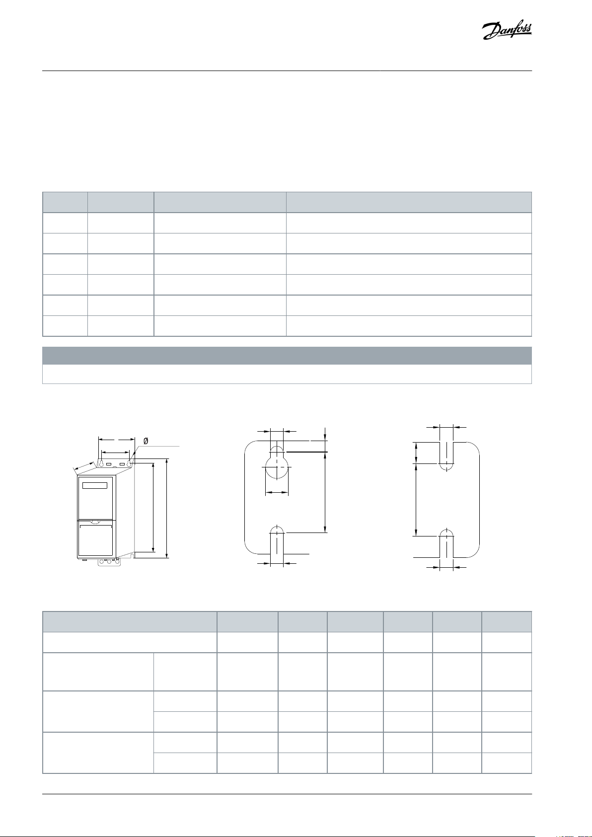
3 Installation
3.1 Mechanical Installation
3.1.1 Side-by-side Installation
The drive can be mounted side by side but requires the clearance above and below for cooling.
Table 4: Clearance Required for Cooling
Installation
The drives are not suitable for outdoor mounting.
3.1.2 Drive Dimensions
Illustration 1: Dimensions
Table 5: Dimensions, Enclosure Sizes I2–I8
N O T I C E
AQ367426199594en-000101 / 130R098810 | Danfoss A/S © 2021.06
Page 11
Enclosure Size
I2I3I4I6I7
I8
Depth [mm (in)]
C
225 (8.9)
237 (9.3)
290 (11.4)
260 (10.2)
310 (12.2)
335 (13.2)
Mounting hole [mm (in)]
d
11 (0.43)
12 (0.47)
12 (0.47)
19 (0.75)
19 (0.75)
19 (0.75)
e
5.5 (0.22)
6.5 (0.26)
6.5 (0.26)
9 (0.35)
9 (0.35)
9 (0.35)
f
9 (0.35)
9.5 (0.37)
9.5 (0.37)
9 (0.35)
9.8 (0.39)
9.8 (0.39)
Maximum weight kg (lb)
5.3 (11.7)
7.2 (15.9)
13.8 (30.42)
27 (59.5)
45 (99.2)
65 (143.3)
Power [kW (hp)]
Torque [Nm (in-lb)]
Enclosure
size
IP class
3x380–480 V
Mains
Motor
DC connection
Control terminals
Ground
Relay
I2
IP54
0.75–4.0 (1.0–5.0)
0.8 (7.0)
0.8 (7.0)
0.8 (7.0)
0.5 (4.0)
0.8 (7.0)
0.5 (4.0)
I3
IP54
5.5–7.5 (7.5–10)
0.8 (7.0)
0.8 (7.0)
0.8 (7.0)
0.5 (4.0)
0.8 (7.0)
0.5 (4.0)
I4
IP54
11–18.5 (15–25)
1.2 (11)
1.2 (11)
0.8 (7.0)
0.5 (4.0)
0.8 (7.0)
0.5 (4.0)
I6
IP54
22–37 (30–50)
4.5 (40)
4.5 (40)
–
0.5 (4.0)
3 (27)
0.6 (5.0)
I7
IP54
45–55 (60–70)
10 (89)
10 (89)
–
0.5 (4.0)
3 (27)
0.6 (5.0)
I8
IP54
75–90 (100–125)
14 (124)/24
(212)
(1)
14 (124)/24
(212)
(1)
–
0.5 (4.0)
3 (27)
0.6 (5.0)
VLT® HVAC Drive FC 131
Operating Guide
The dimensions are only for the physical units. When installing in an application, allow space above and below the units for cooling.
The amount of space for free air passage is listed in 3.1.1 Side-by-side Installation.
Installation
3.2 Electrical Installation
3.2.1 Electrical Installation in General
All cabling must comply with national and local regulations on cable cross-sections and ambient temperature. Copper conductors
are required. 75 °C (167 °F) is recommended.
Table 6: Tightening Torques for Enclosure Sizes I2–I8
1
Cable dimensions ≤95 mm2.
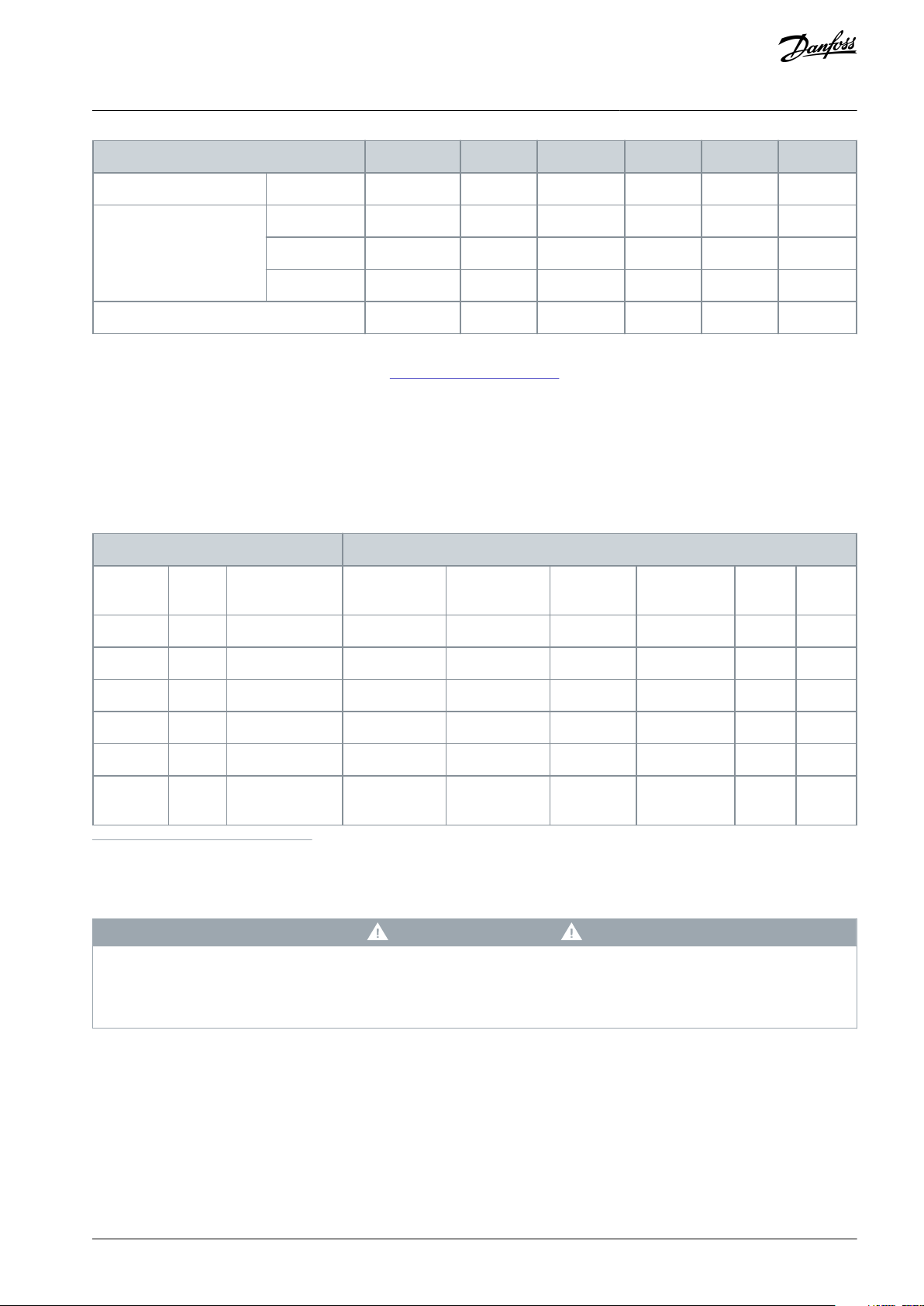
3.2.2 IT Mains
IT MAINS
Installation on isolated mains source, that is, IT mains.
Ensure that the supply voltage does not exceed 440 V (3x380–480 V units) when connected to mains.
-
For IP54, 400 V, 0.75–18.5 kW (1.0–25 hp) units, open the RFI switch by removing the EMC screw inside the drive when at IT grid. The
EMC screw is shown in the the following illustration.
C A U T I O N
AQ367426199594en-000101 / 130R0988 | 11Danfoss A/S © 2021.06
Page 12
e30bc251.10
1
EMC screw
VLT® HVAC Drive FC 131
Operating Guide
Installation
Illustration 2: IP54, 400 V, 0.75–18.5 kW (1–25 hp)
For IP54, 400 V, 22-90 kW (30–125 hp) units, the RFI switch can be opened in parameter 14-50 RFI Filter. Select [1] On to turn the RFI
filter on. The RFI filter ensures that the drive complies with EMC standards. Select [0] Off only when the drive is connected to IT
mains.
N O T I C E
If reinserted, use only M3x12 screw.
3.2.3 Mains and Motor Connection
3.2.3.1 Introduction
The drive is designed to operate all standard 3-phase induction motors.
•
Use a shielded/armored motor cable to comply with EMC emission specifications and connect this cable to the motor.
•
Keep the motor cable as short as possible to reduce the noise level and leakage currents.
•
Also see EMC-Correct Installation in the 3.2.5 EMC-compliant Electrical Installation.
AQ367426199594en-000101 / 130R098812 | Danfoss A/S © 2021.06
Page 13
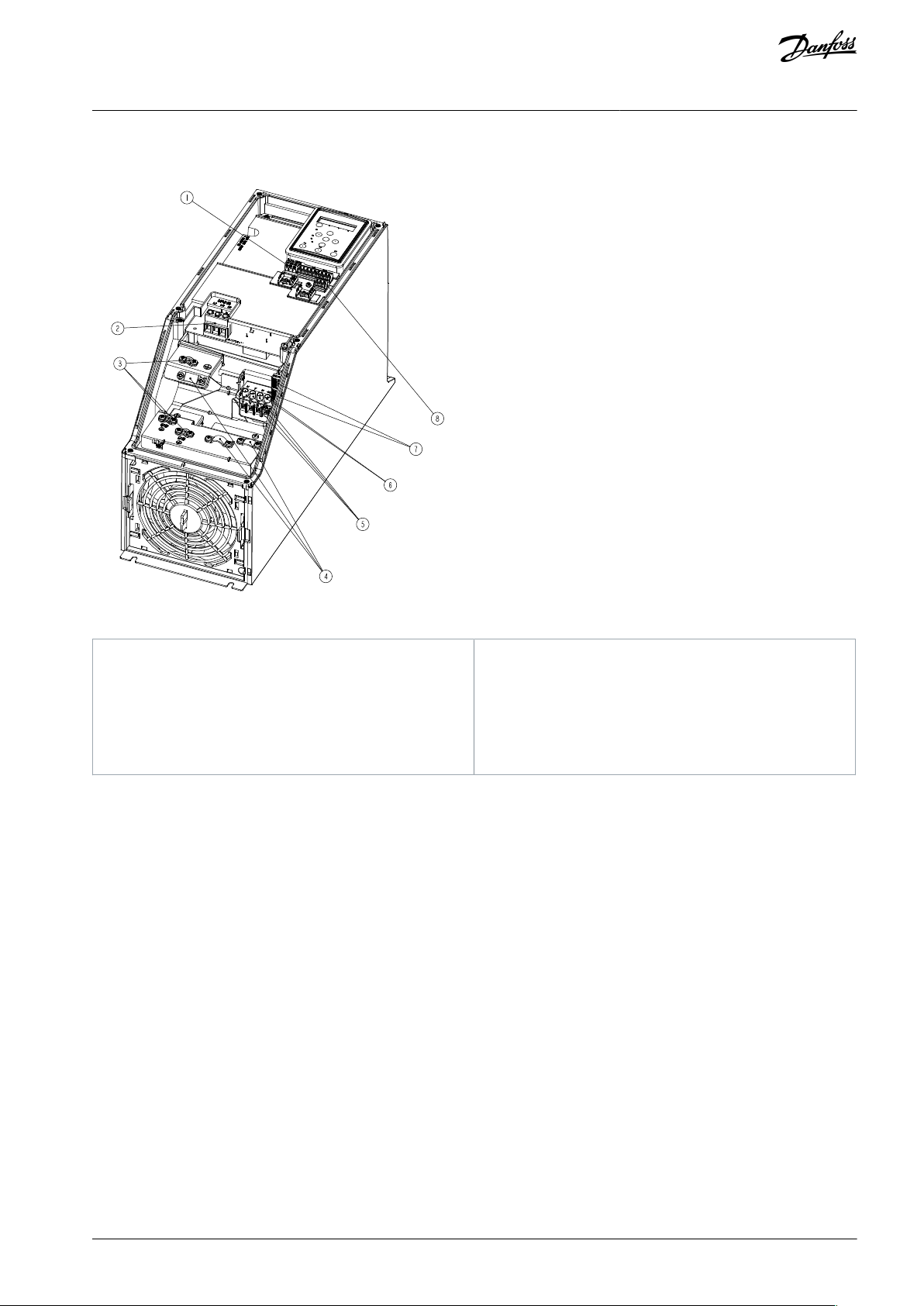
e30bc299.10
7
3
2
5
1
8
4
6
1
RS485
2
Mains
3
Ground
4
Cable clamps
5
Motor
6
UDC7Relays
8
I/O
VLT® HVAC Drive FC 131
Operating Guide
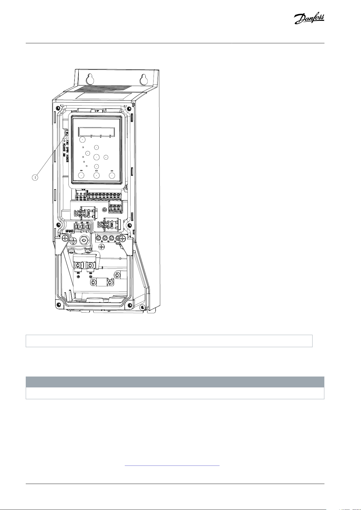
3.2.3.2 Connecting to Mains and Motor
1.
Mount the ground cables to the ground terminal.
2.
Connect the motor to terminals U, V, and W, and then tighten the screws according to the torques.
3.
Connect the mains supply to terminals L1, L2, and L3, and then tighten the screws according to the torques described in
3.2.1 Electrical Installation in General.
3.2.3.3 Enclosure Size I2
Installation
Illustration 3: Enclosure Size I2, IP54, 380–480 V, 0.75–4.0 kW (1.0–5.0 hp)
AQ367426199594en-000101 / 130R0988 | 13Danfoss A/S © 2021.06
Page 14

e30bc201.10
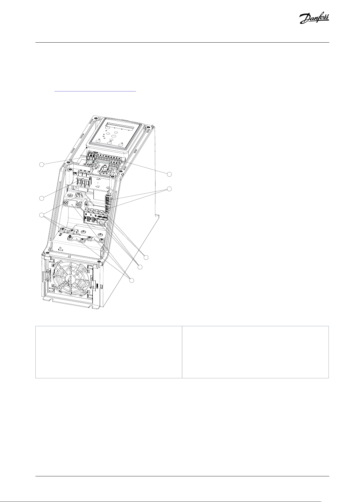
1
RS485
2
Mains
3
Ground
4
Cable clamps
5
Motor
6
UDC7Relays
8
I/O
VLT® HVAC Drive FC 131
Operating Guide
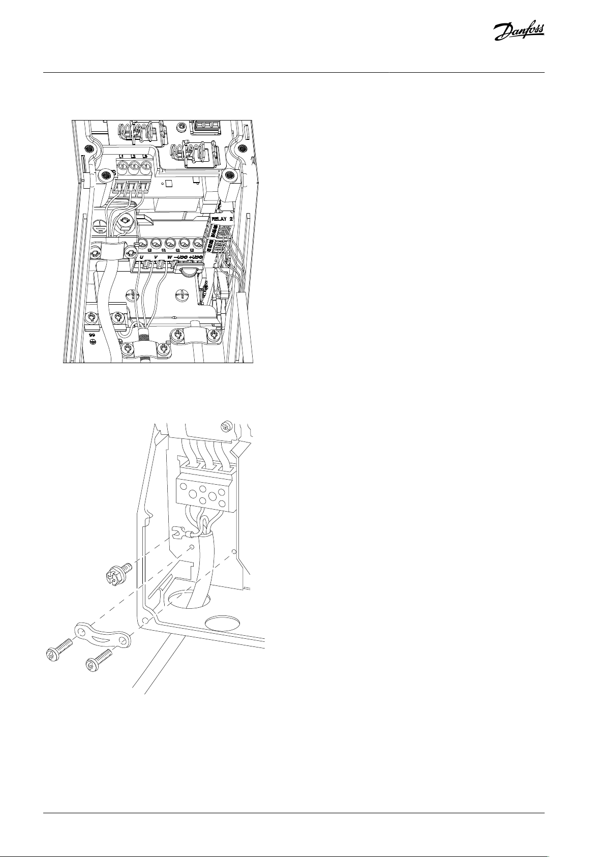
3.2.3.4 Enclosure Size I3
Installation
Illustration 4: Enclosure Size I3, IP54, 380–480 V, 5.5–7.5 kW (7.5–10 hp)
AQ367426199594en-000101 / 130R098814 | Danfoss A/S © 2021.06
Page 15
e30bd011.10
1
RS485
2
Mains
3
Ground
4
Cable clamps
5
Motor
6
UDC7Relays
8
I/O
VLT® HVAC Drive FC 131
Operating Guide
3.2.3.5 Enclosure Size I4
Installation
Illustration 5: Enclosure Size I4, IP54, 380–480 V, 11–18.5 kW (15–25 hp)
AQ367426199594en-000101 / 130R0988 | 15Danfoss A/S © 2021.06
Page 16
e30bc203.10
e30bt326.10
VLT® HVAC Drive FC 131
Operating Guide
3.2.3.6 IP54 Enclosure Sizes I2, I3, I4
Installation
Illustration 6: IP54 Enclosure Sizes I2, I3, I4
3.2.3.7 Enclosure size I6
Illustration 7: Connecting to Mains for Enclosure Size I6, IP54, 380–480 V, 22–37 kW (30–50 hp)
AQ367426199594en-000101 / 130R098816 | Danfoss A/S © 2021.06
Page 17
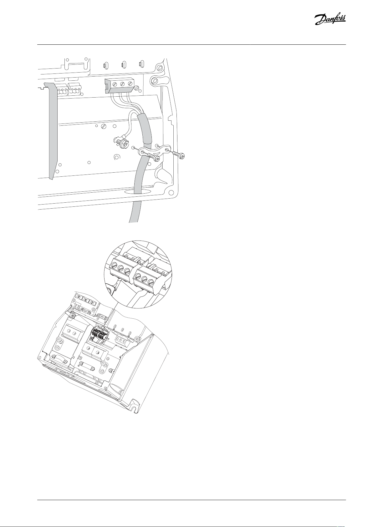
e30bt325.10
311
e30ba215.10
RELA
Y 1
RELA
Y 2
03 02 01
90
05 04
VLT® HVAC Drive FC 131
Operating Guide
Installation
Illustration 8: Connecting to Motor for Enclosure Size I6, IP54, 380–480 V, 22–37 kW (30–50 hp)
Illustration 9: Relays on Enclosure Size I6, IP54, 380–480 V, 22–37 kW (30–50 hp)
AQ367426199594en-000101 / 130R0988 | 17Danfoss A/S © 2021.06
Page 18

91
L1
92
L2
93
L3
96
U
97
V
98
W
88
DC-
99
95
e30bc248.10
Circuit breaker
Fuse
UL
Non-ULULNon-UL
Bussmann
Bussmann
Bussmann
Bussmann
Maximum fuse
Power [kW (hp)]
Type RK5
Type RK1
Type J
Type T
Type G
VLT® HVAC Drive FC 131
Operating Guide
3.2.3.8 Enclosure size I7, I8
Illustration 10: Enclosure Sizes I7, I8, IP54, 380–480 V, 45–55 kW (60–70 hp), IP54, 380–480 V, 75–90 kW (100–125 hp)
Installation
3.2.4 Fuses and Circuit Breakers
3.2.4.1 Branch Circuit Protection
To prevent fire hazards, protect the branch circuits in an installation - switch gear, machines, and so on - against short circuits and
overcurrent. Follow national and local regulations.
3.2.4.2 Short-circuit Protection
Danfoss recommends using the fuses and circuit breakers listed in this chapter to protect service personnel or other equipment in
case of an internal failure in the unit or a short circuit on the DC link. The drive provides full short-circuit protection in case of a short
circuit on the motor.
3.2.4.3 Overcurrent Protection
Provide overload protection to avoid overheating of the cables in the installation. Overcurrent protection must always be carried
out according to local and national regulations. Design circuit breakers and fuses for protection in a circuit capable of supplying a
maximum of 100000 A
(symmetrical), 480 V maximum.
rms
3.2.4.4 UL/Non-UL Compliance
To ensure compliance with UL or IEC 61800-5-1, use the circuit breakers or fuses listed in this chapter. Circuit breakers must be
designed for protection in a circuit capable of supplying a maximum of 10000 A
(symmetrical), 480 V maximum.
rms
3.2.4.5 Recommendation of Fuses and Circuit Breakers
N O T I C E
If a malfunction occurs, failure to follow the protection recommendation may result in damage to the drive.
Table 7: Fuses and Circuit Breakers
AQ367426199594en-000101 / 130R098818 | Danfoss A/S © 2021.06
Page 19

3x380–480 V IP54
0.75 (1.0)
–
PKZM0-16
FRS-R-10
KTS-R-10
JKS-10
JJS-10161.5 (2.0)
PKZM0-16
FRS-R-10
KTS-R-10
JKS-10
JJS-10162.2 (3.0)
PKZM0-16
FRS-R-15
KTS-R-15
JKS-15
JJS-15163.0 (4.0)
PKZM0-16
FRS-R-15
KTS-R-15
JKS-15
JJS-15164.0 (5.0)
PKZM0-16
FRS-R-15
KTS-R-15
JKS-15
JJS-15165.5 (7.5)
PKZM0-25
FRS-R-25
KTS-R-25
JKS-25
JJS-25257.5 (10)
PKZM0-25
FRS-R-25
KTS-R-25
JKS-25
JJS-252511 (15)
PKZM4-63
FRS-R-50
KTS-R-50
JKS-50
JJS-506315 (20)
PKZM4-63
FRS-R-50
KTS-R-50
JKS-50
JJS-506318.5 (25)
PKZM4-63
FRS-R-80
KTS-R-80
JKS-80
JJS-806322 (30)
Moeller NZMB1-A125
–
FRS-R-80
KTS-R-80
JKS-80
JJS-80
125
30 (40)
FRS-R-125
KTS-R-125
JKS-125
JJS-125
125
37 (50)
FRS-R-125
KTS-R-125
JKS-125
JJS-125
125
45 (60)
Moeller NZMB2-A160
–
FRS-R-125
KTS-R-125
JKS-125
JJS-125
160
55 (70)
FRS-R-200
KTS-R-200
JKS-200
JJS-200
160
75 (100)
Moeller NZMB2-A250
–
FRS-R-200
KTS-R-200
JKS-200
JJS-200
200
90 (125)
FRS-R-250
KTS-R-250
JKS-200
JJS-200
200
VLT® HVAC Drive FC 131
Operating Guide
Installation
3.2.5 EMC-compliant Electrical Installation
To ensure EMC-correct electrical installation, observe the following:
•
Use only shielded/armored motor cables and shielded/armored control cables.
•
Ground the shield at both ends.
•
Avoid installation with twisted shield ends (pigtails), because it reduces the shielding effect at high frequencies. Use the cable
clamps provided.
•
Ensure the same potential between the drive and the ground potential of PLC.
•
Use star washers and galvanically conductive installation plates.
AQ367426199594en-000101 / 130R0988 | 19Danfoss A/S © 2021.06
Page 20

B
a
c
k
OK
Com.
On
Warn.
Alarm
Hand
On
Reset
Auto
On
Menu
Status Quick
Menu
Main
Menu
L1
L2
L3
PE
Minimum 16 mm
2
equalizing cable
Control cables
All cable entries in
one side of the panel
Grounding rail
Cable insulation stripped
Output contactor
Motor cable
Motor, 3 phases and
PLC
Panel
Mains-supply
Minimum 200 mm (7.87 in)
between control
cable, mains cable,
and between mains
motor cable
PLC
protective earth
Reinforced protective earth
e30bb761.13
(6 AWG)
VLT® HVAC Drive FC 131
Operating Guide
Installation
Illustration 11: EMC-compliant Installation
3.2.6 Control Terminals
Remove the terminal cover to access the control terminals.
Use a flat-edged screwdriver to push down the lock lever of the terminal cover under the LCP, then remove the terminal cover as
shown in the following illustration.
For IP54 units, control terminals can be accessed after removing the front cover.
AQ367426199594en-000101 / 130R098820 | Danfoss A/S © 2021.06
Page 21

e30bd331.10
e30bf892.10
12 20 55
181927 29 42 54
45 50 53
DIGI IN
61 68 69
N
P
COMM. GND
+24 V
GND
GND
10 V OUT
10 V/20 mA IN
0/4-20 mA A OUT/DIG OUT
BUS TER.
OFF ON
DIGI IN
DIGI IN
DIGI IN
0/4-20 mA A OUT/DIG OUT
10 V/20 mA IN
VLT® HVAC Drive FC 131
Operating Guide
Installation
Illustration 12: Removing the Terminal Cover
The following illustration shows all the drive control terminals. Applying start (terminal 18), connection between terminals 12-27,
and an analog reference (terminal 53 or 54, and 55) make the drive run.
The digital input mode of terminal 18, 19, and 27 is set in parameter 5-00 Digital Input Mode (PNP is default value). Digital input 29
mode is set in parameter 5-03 Digital Input 29 Mode (PNP is default value).
Illustration 13: Control Terminals
AQ367426199594en-000101 / 130R0988 | 21Danfoss A/S © 2021.06
Page 22

L1
L2
L3
3-phase
power
input
PE
PE
+10 V DC
0-10 V DC-
0-10 V DC-
50 (+10 V OUT)
54 (A IN)
53 (A IN)
55 (COM A IN/OUT)
0/4-20 mA
0/4-20 mA
42 0/4-20 mA A OUT / D OUT
45 0/4-20 mA A OUT / D OUT
18 (D IN)
19 (D IN)
27 (D IN/OUT)
29 (D IN/OUT)
12 (+24 V OUT)
24 V (NPN)
20 (COM D IN)
O V (PNP)
24 V (NPN)
O V (PNP)
24 V (NPN)
O V (PNP)
24 V (NPN)
O V (PNP)
Bus ter.
Bus ter.
RS485
Interface
RS485
(N RS485) 69
(P RS485) 68
(Com RS485 ) 61
(PNP)-Source
(NPN)-Sink
ON=Terminated
OFF=Unterminated
ON
1 2
240 V AC 3 A
Not present on all power sizes
Do not connect shield to 61
01
02
03
relay 1
relay 2
UDC+
UDC-
Motor
U
V
W
e30bd467.13
06
05
04
240 V AC 3 A
VLT® HVAC Drive FC 131
Operating Guide
3.2.7 Electrical Wiring
Installation
Illustration 14: Basic Wiring Schematic Drawing
N O T I C E
There is no access to UDC- and UDC+ on the following units:
IP54, 380–480 V, 22–90 kW (30–125 hp)
-
3.2.8 Acoustic Noise or Vibration
If the motor or the equipment driven by the motor - for example, a fan - is making noise or vibrations at certain frequencies, configure the following parameters or parameter groups to reduce or eliminate the noise or vibrations:
•
Parameter group 4-6* Speed Bypass.
•
Set parameter 14-03 Overmodulation to [0] Off.
•
Switching pattern and switching frequency parameter group 14-0* Inverter Switching.
•
Parameter 1-64 Resonance Dampening.
AQ367426199594en-000101 / 130R098822 | Danfoss A/S © 2021.06
Page 23

e30bu820.10
B
C
D
A
13 14 15
12
11
11
5
4
10
6
7
8
9
1
2
11
1 (2)
3
1
Parameter number and name.
2
Parameter value.
3
Setup number shows the active setup and the edit setup (only in Status menu). The number outside brackets is active setup,
and the number inside brackets is edit setup. For example, 1(2) means 1 is the active setup, and 2 is the edit setup.
4
Motor direction is shown to the bottom left of the display – indicated by a small arrow pointing either clockwise or counterclockwise.
5
The triangle indicates if the LCP is in Status, Quick Menu, or Main Menu.
VLT® HVAC Drive FC 131
Operating Guide
4 Programming
4.1 Local Control Panel (LCP)
The LCP is divided into 4 functional sections.
•
A. Display
•
B. Menu key
•
C. Navigation keys and indicator lights
•
D. Operation keys and indicator lights
Programming
Illustration 15: Local Control Panel (LCP 32)
A. Display
The graphical LCD-display is illuminated with clear white backlight and can show either 3 full lines (in programming mode) or 2 full
& 2 ½ lines (in status mode). The following table describes the information that can be read from the display.
Table 8: Legend to Section A, Illustration 3
B. Menu key
Press [Menu] to select among Status, Quick Menu, or Main Menu.
AQ367426199594en-000101 / 130R0988 | 23Danfoss A/S © 2021.06
Page 24

6
Com. (yellow indicator): Flashes during bus communication.
7
On (green indicator): Shows the power on status.
8
Warn. (yellow indicator): Indicates a warning.
9
Alarm (red indicator): Indicates an alarm.
10
[Back]: For moving to the previous step or layer in the navigation structure.
11
Up arrow key, down arrow key, and right arrow key: For navigating among parameter groups and parameters, and within
parameters. They can also be used for setting local reference.
12
[OK]: For selecting a parameter and for accepting changes to parameter settings.
13
[Hand On]: Starts the motor and enables control of the drive via the LCP.
N O T I C E
[2] Coast inverse is the default option for parameter 5-12 Terminal 27 Digital Input. If there is no 24 V supply to terminal 27,
[Hand On] does not start the motor. Connect terminal 12 to terminal 27.
14
[Off/Reset]: Stops the compressor (Off). If in alarm mode, the alarm is reset.
15
[Auto On]: The drive is controlled either via control terminals or serial communication.
FC
+24 V (OUT)
DIG IN
DIG IN
DIG IN
DIG IN
COM DIG IN
A OUT / D OUT
A OUT / D OUT
18
19
27
29
42
55
50
53
54
20
12
01
02
03
04
05
06
R2
R1
+
0–10 V
Start
+10 V (OUT)
A IN
A IN
COM IN/OUT
45
Reference
e30bb674.11
VLT® HVAC Drive FC 131
Operating Guide
C. Navigation keys and indicator lights
Table 9: Legend to Section C, Illustration 3
D. Operation keys and indicator lights
Table 10: Legend to Section D, Illustration 3
Programming
4.2 Set-up Wizard
4.2.1 Setup Wizard Introduction
The built-in wizard menu guides the installer through the setup of the drive in a clear and structured manner for open-loop and
closed-loop applications, and for quick motor settings.
Illustration 16: Drive Wiring
The wizard can always be accessed again through the quick menu. Press [OK] to start the wizard. Press [Back] to return to the status
view.
AQ367426199594en-000101 / 130R098824 | Danfoss A/S © 2021.06
Page 25

Power kW/50 H z
Motor Power
Motor Voltage
Motor Frequency
Motor Current
Motor nominal speed
if
Select Regional Settings
... the Wizard starts
200-240V/50Hz/Delta
Grid Type
Induction motor
Asynchronous
Motor Type
Motor current
Motor nominal speed
Motor Cont. Rated Torque
Stator resistance
Motor poles
Back EMF at 1000 rpm
Motor type = IPM
Motor type = SPM
d-axis Inductance Sat. (LdSat)
[0]
[0]
3.8
A
3000
RPM
5.4
Nm
0.65
Ohms
8
Start Mode
Rotor Detection
[0]
Position Detection Gain
%
Off
100
Locked Rotor Detection
[0]
s
Locked Rotor Detection Time[s]
0.10
57
V
5
mH
q-axis Inductance (Lq)
5
mH
1.10
kW
400
V
50
Hz
Max Output Frequency
65
Hz
Motor Cable Length
50
m
4.66
A
1420
RPM
[0]
PM motor
Set Motor Speed low Limit
Hz
Set Motor Speed high Limit
Hz
Set Ramp 1 ramp-up time
s
Set Ramp 1 ramp-down Time
s
Active Flying start ?
Disable
Set T53 low Voltage
V
Set T53 high Voltage
V
Set T53 Low Current
A
Set T53 High Current
A
Voltage
AMA Failed
AMA Failed
Automatic Motor Adaption
Auto Motor Adapt OK
Press OK
Select Function of Relay 2
No function
Off
Select Function of Relay 1
[0] No function
Set Max Reference
Hz
Hz
Set Min Reference
AMA running
-----
Do AMA
(Do not AMA)
AMA OK
[0]
[0]
[0]
Select T53 Mode
Current
Current
Motor type = Induction
Motor type = PM motor
0000
0050
0010
0010
[0]
[0]
04.66
13.30
0050
0220
0000
0050
The next screen is
the Wizard screen.
Power-up Screen
e30bu808.11
q-axis Inductance Sat. (LqSat)
5
mH
Current at Min Inductance for d-axis
100
%
Current at Min Inductance for q-axis
100
%
d-axis Inductance (Lq)
5
mH
... the Wizard starts
1 (1)
0.0 Hz
0.000 kW
Auto On
0-**: FC-xxx Wizard
1-**: Closed Loop Set
2-**: Motor Setup
Or
VLT® HVAC Drive FC 131
Operating Guide
4.2.2 Setup Wizard for Open-loop Applications
Programming
Illustration 17: Setup Wizard for Open-loop Applications
AQ367426199594en-000101 / 130R0988 | 25Danfoss A/S © 2021.06
Page 26

•
•
•
•
•
•
•
•
•
•
•
•
•
•
•
•
Parameter
Option/range
Default
Usage
Parameter 0-03
Regional Settings
[0] International
[1] US
[0] International
–
Parameter 0-06
GridType
[0] 200–240 V/50 Hz/IT-grid
[1] 200–240 V/50 Hz/Delta
[2] 200–240 V/50 Hz
[10] 380–440 V/50 Hz/IT-grid
[11] 380–440 V/50 Hz/Delta
[12] 380–440 V/50 Hz
[20] 440–480 V/50 Hz/IT-grid
[21] 440–480 V/50 Hz/Delta
[22] 440–480 V/50 Hz
[30] 525–600 V/50 Hz/IT-grid
[31] 525–600 V/50 Hz/Delta
[32] 525–600 V/50 Hz
[100] 200–240 V/60 Hz/IT-grid
[101] 200–240 V/60 Hz/Delta
[102] 200–240 V/60 Hz
[110] 380–440 V/60 Hz/IT-grid
[111] 380–440 V/60 Hz/Delta
[112] 380–440 V/60 Hz
[120] 440–480 V/60 Hz/IT-grid
[121] 440–480 V/60 Hz/Delta
[122] 440–480 V/60 Hz
[130] 525–600 V/60 Hz/IT-grid
[131] 525–600 V/60 Hz/Delta
[132] 525–600 V/60 Hz
Size related
Select the operating mode for restart after reconnection of
the drive to mains voltage after power down.
Parameter 1-10
Motor Construction
*[0] Asynchron
[1] PM, non-salient SPM
[3] PM, salient IPM
[0] Asynchron
Setting the parameter value might change these parameters:
Parameter 1-01 Motor Control Principle.
Parameter 1-03 Torque Characteristics.
Parameter 1-08 Motor Control Bandwidth.
Parameter 1-14 Damping Gain.
Parameter 1-15 Low Speed Filter Time Const.
Parameter 1-16 High Speed Filter Time Const.
Parameter 1-17 Voltage Filter Time Const.
Parameter 1-20 Motor Power.
Parameter 1-22 Motor Voltage.
Parameter 1-23 Motor Frequency.
Parameter 1-24 Motor Current.
Parameter 1-25 Motor Nominal Speed.
Parameter 1-26 Motor Cont. Rated Torque.
Parameter 1-30 Stator Resistance (Rs).
Parameter 1-33 Stator Leakage Reactance (X1).
Parameter 1-35 Main Reactance (Xh).
VLT® HVAC Drive FC 131
Operating Guide
Table 11: Setup Wizard for Open-loop Applications
Programming
AQ367426199594en-000101 / 130R098826 | Danfoss A/S © 2021.06
Page 27

•
•
•
•
•
•
•
•
•
•
•
•
•
•
•
•
•
•
•
•
•
•
•
•
•
Parameter
Option/range
Default
Usage
Parameter 1-37 d-axis Inductance (Ld).
Parameter 1-38 q-axis Inductance (Lq).
Parameter 1-39 Motor Poles.
Parameter 1-40 Back EMF at 1000 RPM.
Parameter 1-44 d-axis Inductance Sat. (LdSat).
Parameter 1-45 q-axis Inductance Sat. (LqSat).
Parameter 1-46 Position Detection Gain.
Parameter 1-48 Current at Min Inductance for d-axis.
Parameter 1-49 Current at Min Inductance for q-axis.
Parameter 1-66 Min. Current at Low Speed.
Parameter 1-70 PM Start Mode.
Parameter 1-72 Start Function.
Parameter 1-73 Flying Start.
Parameter 1-80 Function at Stop.
Parameter 1-82 Min Speed for Function at Stop [Hz].
Parameter 1-90 Motor Thermal Protection.
Parameter 2-00 DC Hold/Motor Preheat Current.
Parameter 2-01 DC Brake Current.
Parameter 2-02 DC Braking Time.
Parameter 2-04 DC Brake Cut In Speed.
Parameter 2-10 Brake Function.
Parameter 4-14 Motor Speed High Limit [Hz].
Parameter 4-19 Max Output Frequency.
Parameter 4-58 Missing Motor Phase Function.
Parameter 14-65 Speed Derate Dead Time Compensation.
Parameter 1-20
Motor Power
0.18–110 kW/0.25–150 hp
Size related
Enter the motor power from the nameplate data.
Parameter 1-22
Motor Voltage
50–1000 V
Size related
Enter the motor voltage from the nameplate data.
Parameter 1-23
Motor Frequency
20–400 Hz
Size related
Enter the motor frequency from the nameplate data.
Parameter 1-24
Motor Current
0.01–1000.00 A
Size related
Enter the motor current from the nameplate data.
Parameter 1-25
Motor Nominal
Speed
50–9999 RPM
Size related
Enter the motor nominal speed from the nameplate data.
Parameter 1-26
Motor Cont.
Rated Torque
0.1–1000.0 Nm
Size related
This parameter is available when parameter 1-10 Motor Con-
struction is set to options that enable permanent motor
mode.
VLT® HVAC Drive FC 131
Operating Guide
Programming
AQ367426199594en-000101 / 130R0988 | 27Danfoss A/S © 2021.06
Page 28

Parameter
Option/range
Default
Usage
N O T I C E
Changing this parameter affects the settings of other pa-
rameters.
Parameter 1-29
Automatic Motor Adaption
(AMA)
See parameter 1-29 Automatic
Motor Adaption (AMA).
Off
Performing an AMA optimizes motor performance.
Parameter 1-30
Stator Resistance (Rs)
0.000–99.990 Ω
Size related
Set the stator resistance value.
Parameter 1-37
d-axis Inductance (Ld)
0.000–1000.000 mH
Size related
Enter the value of the d-axis inductance. Obtain the value
from the permanent magnet motor datasheet.
Parameter 1-38
q-axis Inductance (Lq)
0.000–1000.000 mH
Size related
Enter the value of the q-axis inductance.
Parameter 1-39
Motor Poles
2–100
4
Enter the number of motor poles.
Parameter 1-40
Back EMF at
1000 RPM
10–9000 V
Size related
Line-line RMS back EMF voltage at 1000 RPM.
Parameter 1-42
Motor Cable
Length
0–100 m
50 m
Enter the motor cable length.
Parameter 1-44
d-axis Inductance Sat.
(LdSat)
0.000–1000.000 mH
Size related
This parameter corresponds to the inductance saturation of
Ld. Ideally, this parameter has the same value as parameter
1-37 d-axis Inductance (Ld). However, if the motor supplier
provides an induction curve, enter the induction value,
which is 200% of the nominal current.
Parameter 1-45
q-axis Inductance Sat.
(LqSat)
0.000–1000.000 mH
Size related
This parameter corresponds to the inductance saturation of
Lq. Ideally, this parameter has the same value as parameter
1-38 q-axis Inductance (Lq). However, if the motor supplier
provides an induction curve, enter the induction value,
which is 200% of the nominal current.
Parameter 1-46
Position Detection Gain
20–200%
100%
Adjusts the height of the test pulse during position detection at start.
Parameter 1-48
Current at Min
Inductance for
d-axis
20–200%
100%
Enter the inductance saturation point.
Parameter 1-49
Current at Min
Inductance for
q-axis
20–200%
100%
This parameter specifies the saturation curve of the d- and qinductance values. From 20–100% of this parameter, the inductances are linearly approximated due to parameter 1-37
d-axis Inductance (Ld), parameter 1-38 q-axis Inductance (Lq),
parameter 1-44 d-axis Inductance Sat. (LdSat), and parameter
1-45 q-axis Inductance Sat. (LqSat).
VLT® HVAC Drive FC 131
Operating Guide
Programming
AQ367426199594en-000101 / 130R098828 | Danfoss A/S © 2021.06
Page 29

Parameter
Option/range
Default
Usage
Parameter 1-70
PM Start Mode
[0] Rotor Detection
[1] Parking
[3] Rotor Last Position
[1] Parking
Select the PM motor start mode.
Parameter 1-73
Flying Start
[0] Disabled
[1] Enabled
[0] Disabled
Select [1] Enabled to enable the drive to catch a motor spinning due to mains drop-out. Select [0] Disabled if this function is not required. When this parameter is set to [1] Ena-
bled, parameter 1-71 Start Delay and parameter 1-72 Start
Function are not functional. Parameter 1-73 Flying Start is ac-
tive in VVC+ mode only.
Parameter 3-02
Minimum Reference
-4999.000–4999.000
0
The minimum reference is the lowest value obtainable by
summing all references.
Parameter 3-03
Maximum Reference
-4999.000–4999.000
50
The maximum reference is the lowest obtainable by summing all references.
Parameter 3-41
Ramp 1 Ramp
Up Time
0.01–3600.00 s
Size related
If asynchronous motor is selected, the ramp-up time is from
0 to rated parameter 1-23 Motor Frequency. If PM motor is selected, the ramp-up time is from 0 to parameter 1-25 Motor
Nominal Speed.
Parameter 3-42
Ramp 1 Ramp
Down Time
0.01–3600.00 s
Size related
For asynchronous motors, the ramp-down time is from rated
parameter 1-23 Motor Frequency to 0. For PM motors, the
ramp-down time is from parameter 1-25 Motor Nominal
Speed to 0.
Parameter 4-12
Motor Speed
Low Limit [Hz]
0.0–400.0 Hz
0 Hz
Enter the minimum limit for low speed.
Parameter 4-14
Motor Speed
High Limit [Hz]
0.0–400.0 Hz
100 Hz
Enter the maximum limit for high speed.
Parameter 4-19
Max Output
Frequency
0.0–400.0 Hz
100 Hz
Enter the maximum output frequency value. If parameter
4-19 Max Output Frequency is set lower than parameter 4-14
Motor Speed High Limit [Hz], parameter 4-14 Motor Speed High
Limit [Hz] is set equal to parameter 4-19 Max Output Frequency automatically.
Parameter 5-40
Function Relay
See parameter 5-40 Function
Relay.
[9] Alarm
Select the function to control output relay 1.
Parameter 5-40
Function Relay
See parameter 5-40 Function
Relay.
[5] Drive running
Select the function to control output relay 2.
Parameter 6-10
Terminal 53
Low Voltage
0.00–10.00 V
0.07 V
Enter the voltage that corresponds to the low reference value.
Parameter 6-11
Terminal 53
High Voltage
0.00–10.00 V
10 V
Enter the voltage that corresponds to the high reference value.
Parameter 6-12
Terminal 53
Low Current
0.00–20.00 mA
4 mA
Enter the current that corresponds to the low reference value.
VLT® HVAC Drive FC 131
Operating Guide
Programming
AQ367426199594en-000101 / 130R0988 | 29Danfoss A/S © 2021.06
Page 30

Parameter
Option/range
Default
Usage
Parameter 6-13
Terminal 53
High Current
0.00–20.00 mA
20 mA
Enter the current that corresponds to the high reference value.
Parameter 6-19
Terminal 53
mode
[0] Current
[1] Voltage
[1] Voltage
Select if terminal 53 is used for current or voltage input.
Parameter
30-22 Locked
Rotor Detection
[0] Off
[1] On
[0] Off
–
Parameter
30-23 Locked
Rotor Detection
Time [s]
0.05–1 s
0.10 s
–
VLT® HVAC Drive FC 131
Operating Guide
Programming
AQ367426199594en-000101 / 130R098830 | Danfoss A/S © 2021.06
Page 31

6-29 Terminal 54 Mode
[1]
Voltage
6-25 T54 high Feedback
0050
Hz
20-94 PI integral time
0020.00
s
Current
Voltage
This dialog is forced to be set to
[1] Analog input 54
20-00 Feedback 1 source
[1]
Analog input 54
3-10 Preset reference [0]
0.00
3-03 Max Reference
50.00
3-02 Min Reference
0.00
Induction motor
1-73 Flying Start
[0]
No
1-22 Motor Voltage
400
V
1-24 Motor Current
04.66
A
1-25 Motor nominal speed
1420
RPM
3-41 Ramp 1 ramp-up time
0010
s
3-42 Ramp1 ramp-down time
0010
s
0-06 Grid Type
4-12 Motor speed low limit
0016
Hz
4-14 Motor speed high limit
0050
Hz
e30bc402.16
1-20 Motor Power
1.10
kW
1-23 Motor Frequency
50
Hz
6-22 T54 Low Current
A
6-24 T54 low Feedback
0016
Hz
6-23 T54 high Current
13.30
A
6-25 T54 high Feedback
0050
0.01
s
20-81 PI Normal/Inverse Control
[0]
Normal
20-83 PI Normal/Inverse Control
0050
Hz
20-93 PI Proportional Gain
00.50
1-29 Automatic Motor Adaption
[0]
Off
6-20 T54 low Voltage
0050
V
6-24 T54 low Feedback
0016
Hz
6-21 T54 high Voltage
0220
V
6-26
T54 Filter time const.
1-00 Configuration Mode
[3]
Closed Loop
0-03 Regional Settings
[0]
Power kW/50 Hz
3-16 Reference Source 2
[0]
No Operation
1-10 Motor Type
[0]
Asynchronous
[0]
200-240V/50Hz/Delta
1-30 Stator Resistance
0.65
Ohms
1-25 Motor Nominal Speed
3000
RPM
1-24 Motor Current
3.8
A
1-26 Motor Cont. Rated Torque
5.4
Nm
1-38 q-axis inductance(Lq)
5
mH
4-19 Max Ouput Frequency
0065
Hz
1-40 Back EMF at 1000 RPM
57
V
PM motor
1-39 Motor Poles
8
%
04.66
Hz
Motor type = Induction
Motor type = PM motor
Motor type = IPM
Motor type = SPM
1-44 d-axis Inductance Sat. (LdSat)
(1-70) Start Mode
Rotor Detection
[0]
1-46 Position Detection Gain
%
Off
100
30-22 Locked Rotor Detection
[0]
s
30-23 Locked Rotor Detection Time[s]
0.10
5
mH
1-42 Motor Cable Length
50
m
(1-45) q-axis Inductance Sat. (LqSat)
5
mH
(1-48) Current at Min Inductanc e for d-axis
100
%
1-49 Current at Min Inductanc e for q-axis
100
%
1-37 d-axis inductance(Lq)
5
mH
... the Wizard starts
... the Wizard starts
VLT® HVAC Drive FC 131
Operating Guide
4.2.3 Setup Wizard for Closed-loop Applications
Programming
Illustration 18: Setup Wizard for Closed-loop Applications
AQ367426199594en-000101 / 130R0988 | 31Danfoss A/S © 2021.06
Page 32

•
•
•
•
•
•
•
•
•
•
•
•
•
Parameter
Option/range
Default
Usage
Parameter 0-03
Regional Settings
[0] International
[1] US
[0] International
–
Parameter 0-06
GridType
[0] 200–240 V/50 Hz/IT-grid
[1] 200–240 V/50 Hz/Delta
[2] 200–240 V/50 Hz
[10] 380–440 V/50 Hz/IT-grid
[11] 380–440 V/50 Hz/Delta
[12] 380–440 V/50 Hz
[20] 440–480 V/50 Hz/IT-grid
[21] 440–480 V/50 Hz/Delta
[22] 440–480 V/50 Hz
[30] 525–600 V/50 Hz/IT-grid
[31] 525–600 V/50 Hz/Delta
[32] 525–600 V/50 Hz
[100] 200–240 V/60 Hz/IT-grid
[101] 200–240 V/60 Hz/Delta
[102] 200–240 V/60 Hz
[110] 380–440 V/60 Hz/IT-grid
[111] 380–440 V/60 Hz/Delta
[112] 380–440 V/60 Hz
[120] 440–480 V/60 Hz/IT-grid
[121] 440–480 V/60 Hz/Delta
[122] 440–480 V/60 Hz
[130] 525–600 V/60 Hz/IT-grid
[131] 525–600 V/60 Hz/Delta
[132] 525–600 V/60 Hz
Size selected
Select the operating mode for restart after reconnection of
the drive to mains voltage after power down.
Parameter 1-00
Configuration
Mode
[0] Open loop
[3] Closed loop
[0] Open loop
Select [3] Closed loop.
Parameter 1-10
Motor Construction
*[0] Asynchron
[1] PM, non-salient SPM
[3] PM, salient IPM
[0] Asynchron
Setting the parameter value might change these parameters:
Parameter 1-01 Motor Control Principle.
Parameter 1-03 Torque Characteristics.
Parameter 1-08 Motor Control Bandwidth.
Parameter 1-14 Damping Gain.
Parameter 1-15 Low Speed Filter Time Const.
Parameter 1-16 High Speed Filter Time Const.
Parameter 1-17 Voltage Filter Time Const.
Parameter 1-20 Motor Power.
Parameter 1-22 Motor Voltage.
Parameter 1-23 Motor Frequency.
Parameter 1-24 Motor Current.
Parameter 1-25 Motor Nominal Speed.
Parameter 1-26 Motor Cont. Rated Torque.
VLT® HVAC Drive FC 131
Operating Guide
Table 12: Setup Wizard for Closed-loop Applications
Programming
AQ367426199594en-000101 / 130R098832 | Danfoss A/S © 2021.06
Page 33

•
•
•
•
•
•
•
•
•
•
•
•
•
•
•
•
•
•
•
•
•
•
•
•
•
•
•
•
Parameter
Option/range
Default
Usage
Parameter 1-30 Stator Resistance (Rs).
Parameter 1-33 Stator Leakage Reactance (X1).
Parameter 1-35 Main Reactance (Xh).
Parameter 1-37 d-axis Inductance (Ld).
Parameter 1-38 q-axis Inductance (Lq).
Parameter 1-39 Motor Poles.
Parameter 1-40 Back EMF at 1000 RPM.
Parameter 1-44 d-axis Inductance Sat. (LdSat).
Parameter 1-45 q-axis Inductance Sat. (LqSat).
Parameter 1-46 Position Detection Gain.
Parameter 1-48 Current at Min Inductance for d-axis.
Parameter 1-49 Current at Min Inductance for q-axis.
Parameter 1-66 Min. Current at Low Speed.
Parameter 1-70 PM Start Mode.
Parameter 1-72 Start Function.
Parameter 1-73 Flying Start.
Parameter 1-80 Function at Stop.
Parameter 1-82 Min Speed for Function at Stop [Hz].
Parameter 1-90 Motor Thermal Protection.
Parameter 2-00 DC Hold/Motor Preheat Current.
Parameter 2-01 DC Brake Current.
Parameter 2-02 DC Braking Time.
Parameter 2-04 DC Brake Cut In Speed.
Parameter 2-10 Brake Function.
Parameter 4-14 Motor Speed High Limit [Hz].
Parameter 4-19 Max Output Frequency.
Parameter 4-58 Missing Motor Phase Function.
Parameter 14-65 Speed Derate Dead Time Compensation.
Parameter 1-20
Motor Power
0.18–110 kW/0.25–150 hp
Size related
Enter the motor power from the nameplate data.
Parameter 1-22
Motor Voltage
50–1000 V
Size related
Enter the motor voltage from the nameplate data.
Parameter 1-23
Motor Frequency
20–400 Hz
Size related
Enter the motor frequency from the nameplate data.
Parameter 1-24
Motor Current
0.01–1000.00 A
Size related
Enter the motor current from the nameplate data.
Parameter 1-25
Motor Nominal
Speed
50–60000 RPM
Size related
Enter the motor nominal speed from the nameplate data.
Parameter 1-26
Motor Cont.
Rated Torque
0.1–10000.0 Nm
Size related
This parameter is available when parameter 1-10 Motor Con-
struction is set to options that enable permanent motor
mode.
VLT® HVAC Drive FC 131
Operating Guide
Programming
AQ367426199594en-000101 / 130R0988 | 33Danfoss A/S © 2021.06
Page 34

Parameter
Option/range
Default
Usage
N O T I C E
Changing this parameter affects the settings of other pa-
rameters.
Parameter 1-29
Automatic Motor Adaption
(AMA)
–
Off
Performing an AMA optimizes motor performance.
Parameter 1-30
Stator Resistance (Rs)
0.000–9999.000 Ω
Size related
Set the stator resistance value.
Parameter 1-37
d-axis Inductance (Ld)
0.000–1000.000 mH
Size related
Enter the value of the d-axis inductance. Obtain the value
from the permanent magnet motor datasheet.
Parameter 1-38
q-axis Inductance (Lq)
0.000–1000.000 mH
Size related
Enter the value of the q-axis inductance.
Parameter 1-39
Motor Poles
2–100
4
Enter the number of motor poles.
Parameter 1-40
Back EMF at
1000 RPM
10–9000 V
Size related
Line-line RMS back EMF voltage at 1000 RPM.
Parameter 1-42
Motor Cable
Length
0–100 m
50 m
Enter the motor cable length.
Parameter 1-44
d-axis Inductance Sat.
(LdSat)
0.000–1000.000 mH
Size related
This parameter corresponds to the inductance saturation of
Ld. Ideally, this parameter has the same value as parameter
1-37 d-axis Inductance (Ld). However, if the motor supplier
provides an induction curve, enter the induction value,
which is 200% of the nominal current.
Parameter 1-45
q-axis Inductance Sat.
(LqSat)
0.000–1000.000 mH
Size related
This parameter corresponds to the inductance saturation of
Lq. Ideally, this parameter has the same value as parameter
1-38 q-axis Inductance (Lq). However, if the motor supplier
provides an induction curve, enter the induction value,
which is 200% of the nominal current.
Parameter 1-46
Position Detection Gain
20–200%
100%
Adjusts the height of the test pulse during position detection at start.
Parameter 1-48
Current at Min
Inductance for
d-axis
20–200%
100%
Enter the inductance saturation point.
Parameter 1-49
Current at Min
Inductance for
q-axis
20–200%
100%
This parameter specifies the saturation curve of the d- and qinductance values. From 20–100% of this parameter, the inductances are linearly approximated due to parameter 1-37
d-axis Inductance (Ld), parameter 1-38 q-axis Inductance (Lq),
parameter 1-44 d-axis Inductance Sat. (LdSat), and parameter
1-45 q-axis Inductance Sat. (LqSat).
VLT® HVAC Drive FC 131
Operating Guide
Programming
AQ367426199594en-000101 / 130R098834 | Danfoss A/S © 2021.06
Page 35

Parameter
Option/range
Default
Usage
Parameter 1-70
PM Start Mode
[0] Rotor Detection
[1] Parking
[3] Rotor Last Position
[1] Parking
Select the PM motor start mode.
Parameter 1-73
Flying Start
[0] Disabled
[1] Enabled
[0] Disabled
Select [1] Enabled to enable the drive to catch a spinning motor in, for example, fan applications. When PM is selected,
this parameter is enabled.
Parameter 3-02
Minimum Reference
-4999.000–4999.000
0
The minimum reference is the lowest value obtainable by
summing all references.
Parameter 3-03
Maximum Reference
-4999.000–4999.000
50
The maximum reference is the highest value obtainable by
summing all references.
Parameter 3-10
Preset Reference
-100–100%
0
Enter the setpoint.
Parameter 3-41
Ramp 1 Ramp
Up Time
0.05–3600.0 s
Size related
Ramp-up time from 0 to rated parameter 1-23 Motor Frequen-
cy for asynchronous motors. Ramp-up time from 0 to parameter 1-25 Motor Nominal Speed for PM motors.
Parameter 3-42
Ramp 1 Ramp
Down Time
0.05–3600.0 s
Size related
Ramp-down time from rated parameter 1-23 Motor Frequency
to 0 for asynchronous motors. Ramp-down time from param-
eter 1-25 Motor Nominal Speed to 0 for PM motors.
Parameter 4-12
Motor Speed
Low Limit [Hz]
0.0–400.0 Hz
0.0 Hz
Enter the minimum limit for low speed.
Parameter 4-14
Motor Speed
High Limit [Hz]
0.0–400.0 Hz
100 Hz
Enter the minimum limit for high speed.
Parameter 4-19
Max Output
Frequency
0.0–400.0 Hz
100 Hz
Enter the maximum output frequency value. If parameter
4-19 Max Output Frequency is set lower than parameter 4-14
Motor Speed High Limit [Hz], parameter 4-14 Motor Speed High
Limit [Hz] is set equal to parameter 4-19 Max Output Frequency automatically.
Parameter 6-20
Terminal 54
Low Voltage
0.00–10.00 V
0.07 V
Enter the voltage that corresponds to the low reference value.
Parameter 6-21
Terminal 54
High Voltage
0.00–10.00 V
10.00 V
Enter the voltage that corresponds to the high reference value.
Parameter 6-22
Terminal 54
Low Current
0.00–20.00 mA
4.00 mA
Enter the current that corresponds to the low reference value.
Parameter 6-23
Terminal 54
High Current
0.00–20.00 mA
20.00 mA
Enter the current that corresponds to the high reference value.
Parameter 6-24
Terminal 54
-4999–4999
0
Enter the feedback value that corresponds to the voltage or
current set in parameter 6-20 Terminal 54 Low Voltage/param-
eter 6-22 Terminal 54 Low Current.
VLT® HVAC Drive FC 131
Operating Guide
Programming
AQ367426199594en-000101 / 130R0988 | 35Danfoss A/S © 2021.06
Page 36

Parameter
Option/range
Default
Usage
Low Ref./Feedb.
Value
Parameter 6-25
Terminal 54
High Ref./
Feedb. Value
-4999–4999
50
Enter the feedback value that corresponds to the voltage or
current set in parameter 6-21 Terminal 54 High Voltage/pa-
rameter 6-23 Terminal 54 High Current.
Parameter 6-26
Terminal 54 Filter Time Constant
0.00–10.00 s
0.01
Enter the filter time constant.
Parameter 6-29
Terminal 54
mode
[0] Current
[1] Voltage
[1] Voltage
Select if terminal 54 is used for current or voltage input.
Parameter
20-81 PI Normal/Inverse
Control
[0] Normal
[1] Inverse
[0] Normal
Select [0] Normal to set the process control to increase the
output speed when the process error is positive. Select [1] In-
verse to reduce the output speed.
Parameter
20-83 PI Start
Speed [Hz]
0–200 Hz
0 Hz
Enter the motor speed to be attained as a start signal for
commencement of PI control.
Parameter
20-93 PI Proportional Gain
0.00–10.00
0.01
Enter the process controller proportional gain. Quick control
is obtained at high amplification. However, if amplification is
too high, the process may become unstable.
Parameter
20-94 PI Integral Time
0.1–999.0 s
999.0 s
Enter the process controller integral time. Obtain quick control through a short integral time, though if the integral time
is too short, the process becomes unstable. An excessively
long integral time disables the integral action.
Parameter
30-22 Locked
Rotor Detection
[0] Off
[1] On
[0] Off
–
Parameter
30-23 Locked
Rotor Detection
Time [s]
0.05–1.00 s
0.10 s
–
Parameter
Option/range
Default
Usage
Parameter 0-03
Regional Settings
[0] International
[1] US
[0] International
–
Parameter 0-06
GridType
[0] 200–240 V/50 Hz/IT-grid
[1] 200–240 V/50 Hz/Delta
[2] 200–240 V/50 Hz
[10] 380–440 V/50 Hz/IT-grid
[11] 380–440 V/50 Hz/Delta
[12] 380–440 V/50 Hz
Size selected
Select the operating mode for restart after reconnection of
the drive to mains voltage after power down.
VLT® HVAC Drive FC 131
Operating Guide
Programming
4.2.4 Motor Setup
The motor setup wizard guides users through the needed motor parameters.
Table 13: Motor Setup Wizard Settings
AQ367426199594en-000101 / 130R098836 | Danfoss A/S © 2021.06
Page 37

•
•
•
•
•
•
•
•
•
•
•
•
•
•
•
•
•
•
•
•
•
•
•
•
•
Parameter
Option/range
Default
Usage
[20] 440–480 V/50 Hz/IT-grid
[21] 440–480 V/50 Hz/Delta
[22] 440–480 V/50 Hz
[30] 525–600 V/50 Hz/IT-grid
[31] 525–600 V/50 Hz/Delta
[32] 525–600 V/50 Hz
[100] 200–240 V/60 Hz/IT-grid
[101] 200–240 V/60 Hz/Delta
[102] 200–240 V/60 Hz
[110] 380–440 V/60 Hz/IT-grid
[111] 380–440 V/60 Hz/Delta
[112] 380–440 V/60 Hz
[120] 440–480 V/60 Hz/IT-grid
[121] 440–480 V/60 Hz/Delta
[122] 440–480 V/60 Hz
[130] 525–600 V/60 Hz/IT-grid
[131] 525–600 V/60 Hz/Delta
[132] 525–600 V/60 Hz
Parameter 1-10
Motor Construction
*[0] Asynchron
[1] PM, non-salient SPM
[3] PM, salient IPM
[0] Asynchron
Setting the parameter value might change these parameters:
Parameter 1-01 Motor Control Principle.
Parameter 1-03 Torque Characteristics.
Parameter 1-08 Motor Control Bandwidth.
Parameter 1-14 Damping Gain.
Parameter 1-15 Low Speed Filter Time Const.
Parameter 1-16 High Speed Filter Time Const.
Parameter 1-17 Voltage Filter Time Const.
Parameter 1-20 Motor Power.
Parameter 1-22 Motor Voltage.
Parameter 1-23 Motor Frequency.
Parameter 1-24 Motor Current.
Parameter 1-25 Motor Nominal Speed.
Parameter 1-26 Motor Cont. Rated Torque.
Parameter 1-30 Stator Resistance (Rs).
Parameter 1-33 Stator Leakage Reactance (X1).
Parameter 1-35 Main Reactance (Xh).
Parameter 1-37 d-axis Inductance (Ld).
Parameter 1-38 q-axis Inductance (Lq).
Parameter 1-39 Motor Poles.
Parameter 1-40 Back EMF at 1000 RPM.
Parameter 1-44 d-axis Inductance Sat. (LdSat).
Parameter 1-45 q-axis Inductance Sat. (LqSat).
Parameter 1-46 Position Detection Gain.
Parameter 1-48 Current at Min Inductance for d-axis.
Parameter 1-49 Current at Min Inductance for q-axis.
VLT® HVAC Drive FC 131
Operating Guide
Programming
AQ367426199594en-000101 / 130R0988 | 37Danfoss A/S © 2021.06
Page 38

•
•
•
•
•
•
•
•
•
•
•
•
•
•
•
•
Parameter
Option/range
Default
Usage
Parameter 1-66 Min. Current at Low Speed.
Parameter 1-70 PM Start Mode.
Parameter 1-72 Start Function.
Parameter 1-73 Flying Start.
Parameter 1-80 Function at Stop.
Parameter 1-82 Min Speed for Function at Stop [Hz].
Parameter 1-90 Motor Thermal Protection.
Parameter 2-00 DC Hold/Motor Preheat Current.
Parameter 2-01 DC Brake Current.
Parameter 2-02 DC Braking Time.
Parameter 2-04 DC Brake Cut In Speed.
Parameter 2-10 Brake Function.
Parameter 4-14 Motor Speed High Limit [Hz].
Parameter 4-19 Max Output Frequency.
Parameter 4-58 Missing Motor Phase Function.
Parameter 14-65 Speed Derate Dead Time Compensation.
Parameter 1-20
Motor Power
0.18–110 kW/0.25–150 hp
Size related
Enter the motor power from the nameplate data.
Parameter 1-22
Motor Voltage
50–1000 V
Size related
Enter the motor voltage from the nameplate data.
Parameter 1-23
Motor Frequency
20–400 Hz
Size related
Enter the motor frequency from the nameplate data.
Parameter 1-24
Motor Current
0.01–10000.00 A
Size related
Enter the motor current from the nameplate data.
Parameter 1-25
Motor Nominal
Speed
50–9999 RPM
Size related
Enter the motor nominal speed from the nameplate data.
Parameter 1-26
Motor Cont.
Rated Torque
0.1–1000.0 Nm
Size related
This parameter is available when parameter 1-10 Motor Con-
struction is set to options that enable permanent motor
mode.
N O T I C E
Changing this parameter affects the settings of other pa-
rameters.
Parameter 1-30
Stator Resistance (Rs)
0–99.990 Ω
Size related
Set the stator resistance value.
Parameter 1-37
d-axis Inductance (Ld)
0.000–1000.000 mH
Size related
Enter the value of the d-axis inductance. Obtain the value
from the permanent magnet motor datasheet.
VLT® HVAC Drive FC 131
Operating Guide
Programming
AQ367426199594en-000101 / 130R098838 | Danfoss A/S © 2021.06
Page 39

Parameter
Option/range
Default
Usage
Parameter 1-38
q-axis Inductance (Lq)
0.000–1000.000 mH
Size related
Enter the value of the q-axis inductance.
Parameter 1-39
Motor Poles
2–100
4
Enter the number of motor poles.
Parameter 1-40
Back EMF at
1000 RPM
10–9000 V
Size related
Line-line RMS back EMF voltage at 1000 RPM.
Parameter 1-42
Motor Cable
Length
0–100 m
50 m
Enter the motor cable length.
Parameter 1-44
d-axis Inductance Sat.
(LdSat)
0.000–1000.000 mH
Size related
This parameter corresponds to the inductance saturation of
Ld. Ideally, this parameter has the same value as parameter
1-37 d-axis Inductance (Ld). However, if the motor supplier
provides an induction curve, enter the induction value,
which is 200% of the nominal current.
Parameter 1-45
q-axis Inductance Sat.
(LqSat)
0.000–1000.000 mH
Size related
This parameter corresponds to the inductance saturation of
Lq. Ideally, this parameter has the same value as parameter
1-38 q-axis Inductance (Lq). However, if the motor supplier
provides an induction curve, enter the induction value,
which is 200% of the nominal current.
Parameter 1-46
Position Detection Gain
20–200%
100%
Adjusts the height of the test pulse during position detection at start.
Parameter 1-48
Current at Min
Inductance for
d-axis
20–200%
100%
Enter the inductance saturation point.
Parameter 1-49
Current at Min
Inductance for
q-axis
20–200%
100%
This parameter specifies the saturation curve of the d- and qinductance values. From 20–100% of this parameter, the inductances are linearly approximated due to parameter 1-37
d-axis Inductance (Ld), parameter 1-38 q-axis Inductance (Lq),
parameter 1-44 d-axis Inductance Sat. (LdSat), and parameter
1-45 q-axis Inductance Sat. (LqSat).
Parameter 1-70
PM Start Mode
[0] Rotor Detection
[1] Parking
[3] Rotor Last Position
[1] Parking
Select the PM motor start mode.
Parameter 1-73
Flying Start
[0] Disabled
[1] Enabled
[0] Disabled
Select [1] Enabled to enable the drive to catch a spinning motor.
Parameter 3-41
Ramp 1 Ramp
Up Time
0.05–3600.0 s
Size related
Ramp-up time from 0 to rated parameter 1-23 Motor Frequen-
cy.
Parameter 3-42
Ramp 1 Ramp
Down Time
0.05–3600.0 s
Size related
Ramp-down time from rated parameter 1-23 Motor Frequency
to 0.
VLT® HVAC Drive FC 131
Operating Guide
Programming
AQ367426199594en-000101 / 130R0988 | 39Danfoss A/S © 2021.06
Page 40

Parameter
Option/range
Default
Usage
Parameter 4-12
Motor Speed
Low Limit [Hz]
0.0–400.0 Hz
0.0 Hz
Enter the minimum limit for low speed.
Parameter 4-14
Motor Speed
High Limit [Hz]
0.0–400.0 Hz
100.0 Hz
Enter the maximum limit for high speed.
Parameter 4-19
Max Output
Frequency
0.0–400.0 Hz
100.0 Hz
Enter the maximum output frequency value. If parameter
4-19 Max Output Frequency is set lower than parameter 4-14
Motor Speed High Limit [Hz], parameter 4-14 Motor Speed High
Limit [Hz] is set equal to parameter 4-19 Max Output Frequency automatically.
Parameter
30-22 Locked
Rotor Detection
[0] Off
[1] On
[0] Off
–
Parameter
30-23 Locked
Rotor Detection
Time [s]
0.05–1.00 s
0.10 s
–
VLT® HVAC Drive FC 131
Operating Guide
Programming
4.2.5 Changes Made Function
The changes made function lists all parameters changed from default settings.
•
The list shows only parameters that have been changed in the current edit setup.
•
Parameters that have been reset to default values are not listed.
•
The message Empty indicates that no parameters have been changed.
4.2.6 Changing Parameter Settings
Procedure
1.
To enter the Quick Menu, press the [Menu] key until the indicator in the display is placed above Quick Menu.
2.
Press [▵] [▿] to select the wizard, closed-loop setup, motor setup, or changes made.
3.
Press [OK].
4.
Press [▵] [▿] to browse through the parameters in the Quick Menu.
5.
Press [OK] to select a parameter.
6.
Press [▵] [▿] to change the value of a parameter setting.
7.
Press [OK] to accept the change.
8.
Press either [Back] twice to enter Status, or press [Menu] once to enter the Main Menu.
4.2.7 Accessing All Parameters via the Main Menu
Procedure
1.
Press the [Menu] key until the indicator in the display is placed above Main Menu.
2.
Press [▵] [▿] to browse through the parameter groups.
3.
Press [OK] to select a parameter group.
4.
Press [▵] [▿] to browse through the parameters in the specific group.
5.
Press [OK] to select the parameter.
6.
Press [▵] [▿] to set/change the parameter value.
7.
Press [OK] to accept the change.
AQ367426199594en-000101 / 130R098840 | Danfoss A/S © 2021.06
Page 41

Fault
num-
ber
Alarm/
warning
bit num-
ber
Fault text
Warn-
ing
Alarm
Trip
locked
Cause of problem
216Live zero error
XX–
Signal on terminal 53 or 54 is less than 50% of the value
set in parameter 6-10 Terminal 53 Low Voltage, parameter
6-12 Terminal 53 Low Current, parameter 6-20 Terminal 54
Low Voltage, or parameter 6-22 Terminal 54 Low Current.
See also parameter group 6-0* Analog I/O Mode.
3–No motor
X––
No motor is connected to the output of the drive.
414Mains ph. loss
XXX
Missing phase on the supply side or too high voltage imbalance. Check the supply voltage. See parameter 14-12
Function at Mains Imbalance.
711DC over volt
XX–
DC-link voltage exceeds the limit.
810DC under volt
XX–
DC-link voltage drops below voltage warning low-limit.
99Inverter over-
load
XX–
More than 100% load for a long time.
108Motor ETR
over
XX–
Motor is too hot due to more than 100% load for a long
time. See parameter 1-90 Motor Thermal Protection.
117Motor th over
XX–
Thermistor or thermistor connection is disconnected. See
parameter 1-90 Motor Thermal Protection.
135Over current
XXX
Inverter peak current limit is exceeded.
142Earth fault
–XX
Discharge from output phases to ground.
1612Short circuit
–XX
Short circuit in motor or on motor terminals.
174Ctrl. word TO
XX–
No communication to drive. See parameter group 8-0*
General Settings.
2450Fan fault
XX–
The heat sink cooling fan is not working (only on 400 V,
30–90 kW (40–125 hp) units).
3019U phase loss
–XX
Motor phase U is missing. Check the phase. See parameter
4-58 Missing Motor Phase Function.
3120V phase loss
–XX
Motor phase V is missing. Check the phase. See parameter
4-58 Missing Motor Phase Function.
3221W phase loss
–XX
Motor phase W is missing. Check the phase. See parame-
ter 4-58 Missing Motor Phase Function.
3817Internal fault
–XX
Contact the local Danfoss supplier.
4428Earth fault
–XX
Discharge from output phases to ground, using the value
of parameter 15-31 Alarm Log Value if possible.
4633Control volt-
age fault
–XX
Control voltage is low. Contact the local Danfoss supplier.
VLT® HVAC Drive FC 131
Operating Guide
5 Warnings and Alarms
5.1 List of Warnings and Alarms
Table 14: Warnings and Alarms
Warnings and Alarms
AQ367426199594en-000101 / 130R0988 | 41Danfoss A/S © 2021.06
Page 42

Fault
num-
ber
Alarm/
warning
bit num-
ber
Fault text
Warn-
ing
Alarm
Trip
locked
Cause of problem
472324 V supply
low
XXX
24 V DC supply may be overloaded.
5115AMA U
nom
,
I
nom
–X–
The setting of motor voltage, motor current, and motor
power is wrong. Check the settings.
52–AMA low I
nom
–X–
The motor current is too low. Check the settings.
53–AMA big mo-
tor
–X–
The motor is too big to perform AMA.
54–AMA small
motor
–X–
The motor is too small to perform AMA.
55–AMA par.
range
–X–
The parameter values found from the motor are outside
the acceptable range.
56–AMA user in-
terrupt
–X–
The AMA has been interrupted by the user.
57–AMA timeout
–X–
Try to restart the AMA several times, until the AMA is carried out.
N O T I C E
Repeated runs may heat the motor to a level where the
resistance Rs and Rr are increased. In most cases, how-
ever, this is not critical.
58–AMA internal
XX–
Contact the local Danfoss supplier.
5925Current limit
X––
The current is higher than the value in parameter 4-18 Cur-
rent Limit.
6044External Inter-
lock
–X–
External interlock has been activated. To resume normal
operation, apply 24 V DC to the terminal programmed for
external interlock and reset the drive (via serial communication, digital I/O, or by pressing [Reset] button on the
LCP).
6626Heat sink tem-
perature Low
X––
This warning is based on the temperature sensor in the
IGBT module (on 400 V, 30–90 kW (40–125 hp) units).
691Pwr. card
temp
XXX
The temperature sensor on the power card exceeds the
upper or lower limits.
7036Illegal FC con-
figuration
–XX
The control card and power card are not matched.
79–Illegal power
section configuration
XX–
Internal fault. Contact the local Danfoss supplier.
8029Drive initialised
–X–
All parameter settings are initialized to default settings.
VLT® HVAC Drive FC 131
Operating Guide
Warnings and Alarms
AQ367426199594en-000101 / 130R098842 | Danfoss A/S © 2021.06
Page 43
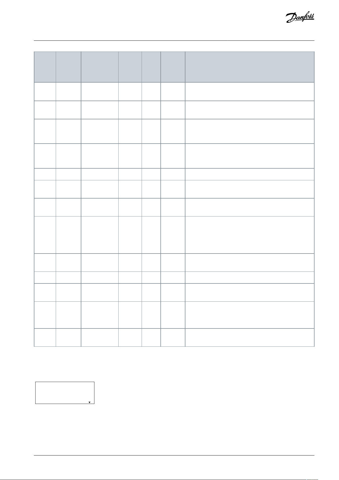
Fault
num-
ber
Alarm/
warning
bit num-
ber
Fault text
Warn-
ing
Alarm
Trip
locked
Cause of problem
92–No-Flow
XX–
A no-flow condition has been detected in the system. Pa-
rameter 22-23 No-Flow Function is set for alarm.
9338Dry pump
XX–
A dry-pump condition has been detected in the system.
Parameter 22-26 Dry Pump Function is set for alarm.
9439End of curve
XX–
An end-of-curve condition has been detected in the system. Parameter 22-50 End of Curve Function is set for
alarm.
9540Broken belt
XX–
Torque is below the torque level set for no load, indicating a broken belt. See parameter group 22-6* Broken Belt
Detection.
99–Locked rotor
–XX
The rotor is blocked.
101
–
Flow/pressure
Info Missing
–––
Sensorless-pump table is missing or wrong. Download
sensorless-pump table again.
126
–
Motor Rotating
–X–
High back EMF voltage. Stop the rotor of the PM motor.
127
–
Back EMF too
high
X––
This warning applies to PM motors only. When the back
EMF exceeds 90% x U
invmax
(overvoltage threshold) and
does not drop to normal level within 5 s, this warning is
reported. The warning remains until the back EMF returns
to a normal level.
159
36
Check valve
failure
X––
When the drive is not in operation, a broken check valve
leads to the motor runs in reverse.
200
–
Fire mode
X––
Fire mode has been activated.
202
–
Fire mode limits exceeded
X––
Fire mode has suppressed 1 or more warranty voiding
alarms.
250
–
New spare
part
–XX
The power or switch mode power supply has been exchanged (on 400 V, 30–90 kW (40–125 hp) units). Contact
the local Danfoss supplier.
251
–
New type
code
–XX
The drive has a new type code (on 400 V, 30–90 kW (40–
125 hp) units). Contact the local Danfoss supplier.
e30bu794.10
0-**: Operation / Dis
1-**: Load and Motor
Button disabled
VLT® HVAC Drive FC 131
Operating Guide
Warnings and Alarms
5.2 LCP Errors Messages
LCP errors are not warnings or alarms. They do not affect the operation of the drive. An LCP error example on the LCP is shown in
the following illustration.
Illustration 19: LCP Error Example
AQ367426199594en-000101 / 130R0988 | 43Danfoss A/S © 2021.06
Page 44

LCP error
code
Error message
Description
Err 84
LCP comm. Lost
Communication between the LCP and the drive is lost.
Err 85
Key disabled
The LCP key is disabled. One of the LCP keys has been disabled in parameter group 0-4*
LCP Keypad.
Err 86
LCP copy failed
Data copy failure. This error occurs when data is copied from drive to LCP, or from LCP to
drive (parameter 0-50 LCP Copy).
Err 88
Data not compatible
LCP data incompatible. This error occurs when data is being copied from LCP to drive
(parameter 0-50 LCP Copy). The typical reason is that data is moved between drive and LCP
that have major software differences.
Err 89
Read only
Parameter read only. An operation is issued via LCP to write a value to a parameter that is
read-only.
Err 90
Database busy
The parameter database of the drive is busy.
Err 91
Parameter invalid
The parameter value that is input via the LCP is invalid.
Err 92
Exceeds limits
The parameter value that is input via the LCP exceeds limits.
Err 93
Motor is running
The LCP copy operation cannot be performed when the drive is running.
Err 95
Not while running
The parameter cannot be changed while the drive is running.
Err 96
Password rejected
The password that is input via the LCP is incorrect.
VLT® HVAC Drive FC 131
Operating Guide
Table 15: LCP Error List
Warnings and Alarms
AQ367426199594en-000101 / 130R098844 | Danfoss A/S © 2021.06
Page 45

Drive
PK75
P1K5
P2K2
P3K0
P4KO
P5K5
P7K5
P11K
P15K
P18K
Typical shaft output [kW]
0.75
1.5
2.2
3.0
4.0
5.5
7.51115
18.5
Typical shaft output [hp]
1.0
2.0
3.0
4.0
5.0
7.5
10.0152025Protection rating IP54
I2I2I2I2I2I3I3I4I4
I4
Maximum cable size in terminals
(mains, motor) [mm2 (AWG)]
4 (10)
4 (10)
4 (10)
4 (10)
4 (10)
4 (10)
4 (10)
16 (6)
16 (6)
16 (6)
Output current at 40°C (104°F) ambient temperature
Continuous (3x380–440 V) [A]
2.2
3.7
5.3
7.2
9.01215.5233137Intermittent (3x380–440 V) [A]
2.4
4.1
5.8
7.9
9.9
13.2
17.1
25.33440.7
Continuous (3x441–480 V) [A]
2.1
3.4
4.8
6.3
8.21114212734Intermittent (3x441–480 V) [A]
2.3
3.7
5.3
6.9
9.0
12.1
15.4
23.1
29.7
37.4
Maximum input current
Continuous (3x380–440 V) [A]
2.1
3.5
4.7
6.3
8.3
11.2
15.1
22.1
29.9
35.2
Intermittent (3x380–440 V) [A]
2.3
3.9
5.2
6.9
9.1
12.3
16.6
24.3
32.9
38.7
Continuous (3x441–480 V) [A]
1.8
2.9
3.9
5.3
6.8
9.4
12.6
18.4
24.7
29.3
Intermittent (3x441–480 V) [A]
2.0
3.2
4.3
5.8
7.5
10.3
13.9
20.2
27.2
32.2
Maximum mains fuses
See 3.2.4.5 Recommendation of Fuses and Circuit Breakers.
Estimated power loss [W], best
case/typical
(1)
21/1646/5746/5866/8395/
118
104/
131
159/
198
248/
274
353/
379
412/
456
Weight enclosure protection rating IP54 [kg (lb)]
5.3
(11.7)
5.3
(11.7)
5.3
(11.7)
5.3
(11.7)
5.3
(11.7)
7.2
(15.9)
7.2
(15.9)
13.8
(30.4)
13.8
(30.4)
13.8
(30.4)
Efficiency [%], best case/typical
(2)
98/
97.6
97.7/
97.2
98.3/
97.9
98.2/
97.8
98/
97.6
98.4/9898.2/
97.8
98.1/
97.9
98/
97.8
98.1/
97.9
Output current at 50°C (122°F) ambient temperature
Continuous (3x380–440 V) [A]
1.93
3.7
4.85
6.3
7.5
10.91420.92833
VLT® HVAC Drive FC 131
Operating Guide
6 Specifications
6.1 Mains Supply
6.1.1 3x380–480 V AC
Table 16: 3x380–480 V AC, 0.75–18.5 kW (1.0–25 hp), Enclosure Sizes I2–I4
Specifications
AQ367426199594en-000101 / 130R0988 | 45Danfoss A/S © 2021.06
Page 46
Drive
PK75
P1K5
P2K2
P3K0
P4KO
P5K5
P7K5
P11K
P15K
P18K
Intermittent (3x380–440 V) [A]
2.1
4.07
5.4
6.9
9.21215.42330.8
36.3
Continuous (3x441–480 V) [A]
1.8
3.4
4.4
5.5
6.81012.6
19.12430
Intermittent (3x441–480 V) [A]
2.0
3.7
4.8
6.1
8.31113.92126.4
33
Drive
P22K
P30K
P37K
P45K
P55K
P75K
P90K
Typical shaft output [kW]
22303745557590
Typical shaft output [hp]
3040506070
100
125
Protection rating IP54
I6I6I6I7I7I8I8
Maximum cable size in terminals
(mains, motor) [mm2 (AWG)]
35 (2)
35 (2)
35 (2)
50 (1)
50 (1)
95 (3/0)
120 (4/0)
Output current at 40°C (104°F) ambient temperature
Continuous (3x380–440 V) [A]
44617390106
147
177
Intermittent (3x380–440 V) [A]
48.4
67.1
80.399116.6
161.7
194.7
Continuous (3x441–480 V) [A]
40526580105
130
160
Intermittent (3x441–480 V) [A]
44
57.2
71.588115.5
143
176
Maximum input current
Continuous (3x380–440 V) [A]
41.85770.3
84.2
102.9
140.3
165.6
Intermittent (3x380–440 V) [A]
46
62.7
77.4
92.6
113.1
154.3
182.2
Continuous (3x441–480 V) [A]
36
49.2
60.6
72.5
88.6
120.9
142.7
Intermittent (3x441–480 V) [A]
39.6
54.1
66.7
79.8
97.5
132.9
157
Maximum mains fuses
See 3.2.4.5 Recommendation of Fuses and Circuit Breakers.
Estimated power loss [W], best
case/typical
(1)
496
734
995
840
1099
1520
1781
Weight enclosure protection rating IP54 [kg (lb)]
27 (59.5)
27 (59.5)
27 (59.5)
45 (99.2)
45 (99.2)
65 (143.3)
65 (143.3)
Efficiency [%], best case/typical
(2)
98
97.8
97.6
98.3
98.2
98.1
98.3
Output current at 50°C (122°F) ambient temperature
Continuous (3x380–440 V) [A]
35.2
48.8
58.46374.2
102.9
123.9
VLT® HVAC Drive FC 131
Operating Guide
1
Applies for dimensioning of drive cooling. If the switching frequency is higher than the default setting, the power losses may increase. LCP and
typical control card power consumptions are included. For power loss data according to EN 50598-2, refer to Danfoss MyDrive® ecoSmart website.
2
Efficiency measured at nominal current. For energy efficiency class, see 6.4.13 Ambient Conditions. For part load losses, see Danfoss MyDrive®
ecoSmart website.
Table 17: 3x380–480 V AC, 22–90 kW (30–125 hp), Enclosure Sizes I6–I8
Specifications
AQ367426199594en-000101 / 130R098846 | Danfoss A/S © 2021.06
Page 47

Drive
P22K
P30K
P37K
P45K
P55K
P75K
P90K
Intermittent (3x380–440 V) [A]
38.7
53.9
64.2
69.3
81.6
113.2
136.3
Continuous (3x441–480 V) [A]
32
41.65256
73.591112
Intermittent (3x441–480 V) [A]
35.2
45.8
57.2
61.6
80.9
100.1
123.2
RFI filter
type
Conduct emission. Maximum shielded cable length [m (ft)]
Radiated emission
Industrial environment
EN 55011
Class A Group 2
Industrial environment
Class A Group 1
Industrial environment
Class B
Housing, trades and
light industries
Class A Group 1
Industrial environment
Class B
Housing, trades
and light industries
EN/IEC
61800-3
Category C3
Second environment
Industrial
Category C2
First environment
Home and office
Category C1
First environment
Home and office
Category C2
First environment
Home and office
Category C1
First environment
Home and office
Without
external
filter
With external
filter
Without
external
filter
With external
filter
Without
external
filter
With
external
filter
Without
external
filter
With
external filter
Without
external
filter
With
external filter
H2 RFI filter (EN 55011 A2, EN/IEC 61800-3 C3)
0.75–18.5
kW (1.0–25
hp) 3x380–
480 V IP54
25 (82)
–––––
Yes–––22–90 kW
(30–120 hp)
3x380–480
V IP54
25 (82)
–––––No–No–
H3 RFI filter (EN55011 A1/B, EN/IEC 61800-3 C2/C1)
0.75–18.5
kW (1.0–25
hp) 3x380–
480 V IP54
––25 (82)
–
10 (33)
–
Yes–––22–90 kW
(30–120 hp)
3x380–480
V IP54
––25 (82)
–
10 (33)
–
Yes–No
–
VLT® HVAC Drive FC 131
Operating Guide
1
Applies for dimensioning of drive cooling. If the switching frequency is higher than the default setting, the power losses may increase. LCP and
typical control card power consumptions are included. For power loss data according to EN 50598-2, refer to Danfoss MyDrive® ecoSmart website.
2
Efficiency measured at nominal current. For energy efficiency class, see 6.4.13 Ambient Conditions. For part load losses, see Danfoss MyDrive®
ecoSmart website.
Specifications
6.2 EMC Emission Test Results
The following test results have been obtained using a system with a drive, a shielded control cable, a control box with potentiometer, and a shielded motor cable.
Table 18: EMC Emission Test Results
AQ367426199594en-000101 / 130R0988 | 47Danfoss A/S © 2021.06
Page 48

Supply voltage
380–480 V ±10%
Supply frequency
50/60 Hz
Maximum imbalance temporary between mains phases
3.0% of rated supply voltage
True power factor (λ)
≥0.9 nominal at rated load
Displacement power factor (cosφ) near unity
(>0.98)
Switching on the input supply L1, L2, L3 (power-ups) enclosure
sizes I2–I4
Maximum 1 time/30 s
Switching on the input supply L1, L2, L3 (power-ups) enclosure
sizes I6–I8
Maximum 1 time/minute
Environment according to EN 60664-1
Overvoltage category III/pollution degree 2
Output voltage
0–100% of supply voltage
Output frequency
0–400 Hz
Switching on output
Unlimited
Ramp times
0.05–3600 s
Maximum motor cable length, shielded/armored (EMC-correct installation)
See 6.2 EMC Emission Test Results.
Maximum motor cable length, unshielded/unarmoured
50 m (164 ft)
Maximum cross-section to motor, mains
See 6.1.1 3x380–480 V AC for more information
Cross-section DC terminals for filter feedback on enclosure sizes
I2–I4
4 mm2/11 AWG
VLT® HVAC Drive FC 131
Operating Guide
Specifications
6.3 Special Conditions
6.3.1 Derating for Ambient Temperature and Switching Frequency
Ensure that the ambient temperature measured over 24 hours is at least 5 °C (9 °F) lower than the maximum ambient temperature
that is specified for the drive. If the drive is operated at a high ambient temperature, decrease the constant output current. For
derating specifications, see the VLT® HVAC Drive FC 131 Design Guide.
6.3.2 Derating for Low Air Pressure and High Altitudes
The cooling capability of air is decreased at low air pressure. For altitudes above 2000 m (6562 ft), contact Danfoss regarding PELV.
Below 1000 m (3281 ft) altitude, derating is not necessary. For altitudes above 1000 m (3281 ft), decrease the ambient temperature
or the maximum output current. Decrease the output by 1% per 100 m (328 ft) altitude above 1000 m (3281 ft) or reduce the maximum ambient cooling air temperature by 1 °C (1.8 °F) per 200 m (656 ft).
6.4 General Technical Data
6.4.1 Protection and Features
•
Electronic motor thermal protection against overload.
•
Temperature monitoring of the heat sink ensures that the drive trips if there is overtemperature.
•
The drive is protected against short circuits between motor terminals U, V, W.
•
When a motor phase is missing, the drive trips and issues an alarm.
•
When a mains phase is missing, the drive trips or issues a warning (depending on the load).
•
Monitoring of the DC-link voltage ensures that the drive trips when the DC-link voltage is too low or too high.
•
The drive is protected against ground faults on motor terminals U, V, W.
6.4.2 Mains Supply (L1, L2, L3)
The unit is suitable for use on a circuit capable of delivering not more than 100000 A
6.4.3 Motor Output (U, V, W)
6.4.4 Cable Length and Cross-section
symmetrical Amperes, 480 V maximum.
rms
AQ367426199594en-000101 / 130R098848 | Danfoss A/S © 2021.06
Page 49

Maximum cross-section to control terminals, rigid wire
2.5 mm2/14 AWG
Maximum cross-section to control terminals, flexible cable
2.5 mm2/14 AWG
Minimum cross-section to control terminals
0.05 mm2/30 AWG
Programmable digital inputs
4
Terminal number
18, 19, 27, 29
Logic
PNP or NPN
Voltage level
0–24 V DC
Voltage level, logic 0 PNP
<5 V DC
Voltage level, logic 1 PNP
>10 V DC
Voltage level, logic 0 NPN
>19 V DC
Voltage level, logic 1 NPN
<14 V DC
Maximum voltage on input
28 V DC
Input resistance, R
i
Approximately 4 kΩ
Digital input 29 as thermistor input
Fault: >2.9 kΩ and no fault: <800 Ω
Digital input 29 as pulse input
Maximum frequency 32 kHz push-pull-driven & 5 kHz (O.C.)
Number of analog inputs
2
Terminal number
53, 54
Terminal 53 mode
Parameter 16-61 Terminal 53 Setting: 1 = voltage, 0 = current
Terminal 54 mode
Parameter 16-63 Terminal 54 Setting: 1 = voltage, 0 = current
Voltage level
0–10 V
Input resistance, R
i
Approximately 10 kΩ
Maximum voltage
20 V
Current level
0/4–20 mA (scalable)
Input resistance, R
i
<500 Ω
Maximum current
29 mA
Resolution on analog input
10 bit
Number of programmable analog outputs
2
Terminal number
42, 45
(1)
Current range at analog output
0/4–20 mA
Maximum load to common at analog output
500 Ω
Maximum voltage at analog output
17 V
Accuracy on analog output
Maximum error: 0.4% of full scale
Resolution on analog output
10 bit
Number of digital outputs
4
Terminals 27 and 29
Terminal number
27, 29
(1)
VLT® HVAC Drive FC 131
Operating Guide
6.4.5 Digital Inputs
Specifications
The digital inputs are galvanically isolated from the supply voltage (PELV) and other high-voltage terminals.
6.4.6 Analog Inputs
6.4.7 Analog Outputs
1
Terminals 42 and 45 can also be programmed as digital outputs.
6.4.8 Digital Output
AQ367426199594en-000101 / 130R0988 | 49Danfoss A/S © 2021.06
Page 50

Voltage level at digital output
0–24 V
Maximum output current (sink and source)
40 mA
Terminals 42 and 45
Terminal number
42, 45
(2)
Voltage level at digital output
17 V
Maximum output current at digital output
20 mA
Maximum load at digital output
1 kΩ
Terminal number
68 (P, TX+, RX+), 69 (N, TX-, RX-)
Terminal number
61 common for terminals 68 and 69
Terminal number
12
Maximum load
80 mA
Programmable relay outputs
2
Relay 01 and 02 (enclosure size I2–I4)
01–03 (NC), 01–02 (NO), 04–06 (NC), 04–05 (NO)
Maximum terminal load (AC-1)
(1)
on 01–02/04–05 (NO) (resistive
load)
250 V AC, 3 A
Maximum terminal load (AC-15)
(1)
on 01–02/04–05 (NO) (induc-
tive load @ cosφ 0.4)
250 V AC, 0.2 A
Maximum terminal load (DC-1)
(1)
on 01–02/04–05 (NO) (resistive
load)
30 V DC, 2 A
Maximum terminal load (DC-13)
(1)
on 01–02/04–05 (NO) (induc-
tive load)
24 V DC, 0.1 A
Maximum terminal load (AC-1)
(1)
on 01–03/04–06 (NC) (resistive
load)
250 V AC, 3 A
Maximum terminal load (AC-15)
(1)
on 01–03/04–06 (NC) (inductive
load @ cosφ 0.4)
250 V AC, 0.2 A
Maximum terminal load (DC-1)
(1)
on 01–03/04–06 (NC) (resistive
load)
30 V DC, 2 A
Minimum terminal load on 01–03 (NC), 01–02 (NO)
24 V DC 10 mA, 24 V AC 20 mA
Environment according to EN 60664-1
Overvoltage category III/pollution degree 2
Programmable relay outputs
Maximum terminal load (AC-1)
(1)
on 01–03 (NC), 01–02 (NO) (resis-
tive load)
240 V AC, 2 A
Maximum terminal load (AC-15)
(1)
(inductive load @ cosφ 0.4)
240 V AC, 0.2 A
Maximum terminal load (DC-1)
(1)
on 01–02 (NO), 01–03 (NC) (resis-
tive load)
60 V DC, 1 A
Maximum terminal load (DC-13)
(1)
(inductive load)
24 V DC, 0.1 A
Relay 01 and 02 terminal number (enclosure size I6–I8)
01–03 (NC), 01–02 (NO), 04–06 (NC), 04– 05 (NO)
VLT® HVAC Drive FC 131
Operating Guide
1
Terminals 27 and 29 can also be programmed as input.
2
Terminals 42 and 45 can also be programmed as analog output.
The digital outputs are galvanically isolated from the supply voltage (PELV) and other high-voltage terminals.
6.4.9 Control Card, RS485 Serial Communication
6.4.10 Control Card, 24 V DC Output
Specifications
6.4.11 Relay Output
1
IEC 60947 parts 4 and 5. Endurance of the relay varies with different load type, switching current, ambient temperature, driving configuration,
working profile, and so forth. It is recommended to mount a snubber circuit when connecting inductive loads to the relays.
AQ367426199594en-000101 / 130R098850 | Danfoss A/S © 2021.06
Page 51

Maximum terminal load (AC-1)
(1)
on 04–05 (NO) (resistive load)
(2)(3)
400 V AC, 2 A
Maximum terminal load (AC-15)
(1)
on 04–05 (NO) (inductive load
@ cosφ 0.4)
240 V AC, 0.2 A
Maximum terminal load (DC-1)
(1)
on 04–05 (NO) (resistive load)
80 V DC, 2 A
Maximum terminal load (DC-13)
(1)
on 04–05 (NO) (inductive load)
24 V DC, 0.1 A
Maximum terminal load (AC-1)
(1)
on 04–06 (NC) (resistive load)
240 V AC, 2 A
Maximum terminal load (AC-15)
(1)
on 04–06 (NC) (inductive load
@ cosφ 0.4)
240 V AC, 0.2 A
Maximum terminal load (DC-1)
(1)
on 04–06 (NC) (resistive load)
50 V DC, 2 A
Maximum terminal load (DC-13)
(1)
on 04–06 (NC) (inductive load)
24 V DC, 0.1 A
Minimum terminal load on 01–03 (NC), 01–02 (NO), 04–06 (NC),
04–05 (NO)
24 V DC 10 mA, 24 V AC 20 mA
Environment according to EN 60664-1
Overvoltage category III/pollution degree 2
Terminal number
50
Output voltage
10.5 V ±0.5 V
Maximum load
25 mA
Enclosure protection rating
IP54 (not for outdoor installation)
Vibration test
1.0 g
Maximum relative humidity
5–95% (IEC 60721-3-3; Class 3K3 (non-condensing)) during opera-
tion
Aggressive environment (IEC 60721-3-3), non-coated enclosure
sizes I2–I8
Class 3C2
Test method according to IEC 60068-2-43 H2S (10 days)
Ambient temperature
(1)
See maximum output current at 40/50 °C (104/122 °F) in 6.1.1
3x380–480 V AC.
Minimum ambient temperature during full-scale operation
0 °C (32 °F)
Minimum ambient temperature at reduced performance, enclosure sizes I2–I4
-20 °C (-4 °F)
Minimum ambient temperature at reduced performance, enclosure sizes I6–I8
-10 °C (14 °F)
Temperature during storage/transport
-30 to +65/70 °C (-22 to +149/158°F)
Maximum altitude above sea level without derating
1000 m (3281 ft)
Maximum altitude above sea level with derating
3000 m (9843 ft)
Safety standards
EN/IEC 61800-5-1
EMC standards, Emission
EN 61800-3, EN 61000-6-3/4, EN 55011, IEC 61800-3
EMC standards, Immunity
EN 61800-3, EN 61000-3-12, EN 61000-6-1/2, EN 61000-4-2, EN
61000-4-3, EN 61000-4-4, EN 61000-4-5, EN 61000-4-6
VLT® HVAC Drive FC 131
Operating Guide
1
IEC 60947 parts 4 and 5. Endurance of the relay varies with different load type, switching current, ambient temperature, driving configuration,
working profile, and so forth. It is recommended to mount a snubber circuit when connecting inductive loads to the relays.
2
Overvoltage Category II.
3
UL applications 300 V AC 2 A.
Specifications
6.4.12 Control Card, 10 V DC Output
6.4.13 Ambient Conditions
AQ367426199594en-000101 / 130R0988 | 51Danfoss A/S © 2021.06
Page 52

Energy efficiency class
(2)
IE2
VLT® HVAC Drive FC 131
Operating Guide
1
Refer to chapter Special Conditions in the operating guide for:
•
Derating for high ambient temperature.
•
Derating for high altitude.
2
Determined according to EN 50598-2 at:
•
Rated load.
•
90% rated frequency.
•
Switching frequency factory setting.
•
Switching pattern factory setting.
Specifications
AQ367426199594en-000101 / 130R098852 | Danfoss A/S © 2021.06
Page 53

VLT® HVAC Drive FC 131
Operating Guide
Index
1
10 V DC output..............................................................................................51
2
24 V DC output..............................................................................................50
A
Additional resource........................................................................................6
Ambient condition.......................................................................................51
Ambient temperature.................................................................................48
Analog input.................................................................................................. 49
B
Branch circuit protection...........................................................................18
C
Certificates and approvals...........................................................................7
Circuit breaker............................................................................................... 18
Control card......................................................................................50, 50, 51
Index
Leakage current...............................................................................................9
Local control panel...................................................................................... 23
Low air pressure............................................................................................48
M
Mains supply (L1, L2, L3)............................................................................48
MCT 10 setup software.......................................................................... 6, 23
Menu key.........................................................................................................23
Motor output (U, V, W)................................................................................48
N
Navigation key...............................................................................................24
O
Operation key................................................................................................ 24
Overcurrent protection..............................................................................18
Overload protection....................................................................................48
P
Programming.................................................................................................23
D
Derating....................................................................................................48, 48
Digital input....................................................................................................49
Digital output................................................................................................ 49
Display..............................................................................................................23
Document version..........................................................................................6
E
Electrical installation................................................................................... 11
EMC-compliant installation...................................................................... 19
Energy efficiency class................................................................................52
F
Fuse................................................................................................................... 18
H
High altitudes................................................................................................ 48
I
Indicator light......................................................................................... 24, 24
Installation
Qualified personnel.............................................................................. 8
L
LCP.....................................................................................................................23
Q
Qualified personnel...................................................................................6, 8
R
Relay output...................................................................................................50
RS485 serial communication....................................................................50
S
Short-circuit protection..............................................................................18
Side-by-side installation............................................................................ 10
Software version............................................................................................. 6
Switching frequency................................................................................... 48
Symbols..............................................................................................................8
U
UL/Non-UL compliance..............................................................................18
V
Voltage
Safety warning........................................................................................8
W
Wiring schematic..........................................................................................22
AQ367426199594en-000101/130R0988 | 53Danfoss A/S © 2021.06
Page 54

Danfoss A/S
Ulsnaes 1
DK-6300 Graasten
vlt-drives.danfoss.com
Danfoss can accept no responsibility for possible errors in catalogs, brochures, and other printed material. Danfoss reserves the right to alter its products without notice. This
also applies to products already on order provided that such alterations can be made without subsequential changes being necessary in specifications already agreed. All
trademarks in this material are property of the respective companies. Danfoss and the Danfoss logotype are trademarks of Danfoss A/S. All rights reserved.
*130R0988*
Danfoss A/S © 2021.06
AQ367426199594en-000101 / 130R0988
*M0030301*
 Loading...