

Page 1
Design Guide
VLT® Flow Drive FC 111
vlt-drives.danfoss.com
Page 2

Page 3

VLT® Flow Drive FC 111
Design Guide
Contents
1
Introduction 10
1.1
Purpose of this Design Guide 10
Additional Resources 10
1.2
Other Resources 10
1.2.1
1.2.2
MCT 10 Set-up Software Support 10
1.3
Document and Software Version 10
1.4
Regulatory Compliance 10
1.4.1
Introduction 10
1.4.2
CE Mark 10
Safety 12
2
Safety Symbols 12
2.1
Qualified Personnel 12
2.2
Contents
Safety Precautions 12
2.3
Product Overview 14
3
3.1
Advantages 14
3.1.1
Why Use a Drive for Controlling Fans and Pumps? 14
3.1.1.1
3.1.1.2
3.1.1.3
3.1.1.4
3.1.1.5
3.1.1.6
3.1.1.7
3.1.1.8
3.1.1.9
3.1.2
Application Examples 20
3.1.2.1
3.1.2.2
The Clear Advantage - Energy Savings 14
Example of Energy Savings 15
Comparison of Energy Savings 15
Example with Varying Flow over 1 Year 17
Better Control 18
Star/Delta Starter or Soft Starter not Required 18
Using a Drive Saves Money 18
Traditional Fan System without a Drive 19
Fan System Controlled by Drives 20
Variable Air Volume 20
Constant Air Volume 21
3.1.2.3
3.1.2.4
3.1.2.5
3.1.2.6
3.1.3
Check Valve Monitoring 26
3.1.4
Dry Pump Detection 26
3.1.5
End of Curve Detection 26
Cooling Tower Fan 22
Condenser Pumps 23
Primary Pumps 24
Secondary Pumps 25
AJ363928382091en-000101/130R0983 | 3Danfoss A/S © 2021.04
Page 4

VLT® Flow Drive FC 111
Design Guide
3.1.6
3.2
Control Structures 26
3.2.1
3.2.2
3.2.3
3.2.4
3.2.5
3.2.6
3.2.7
3.2.8
3.2.9
3.3
Ambient Running Conditions 30
3.3.1
3.3.2
Contents
Time-based Functions 26
Introduction 26
Control Structure Open Loop 27
PM/EC+ Motor Control 27
Local (Hand On) and Remote (Auto On) Control 27
Control Structure Closed Loop 28
Feedback Conversion 28
Reference Handling 28
Tuning the Drive Closed-loop 29
Adjusting the Manual PI 29
Air Humidity 30
Acoustic Noise or Vibration 30
3.3.2.1
3.3.2.2
3.3.3
Aggressive Environments 31
3.4
General Aspects of EMC 31
3.4.1
Overview of EMC Emissions 31
3.4.2
Emission Requirements 32
3.4.3
EMC Emission Test Results 33
3.4.4
Harmonics Emission 34
3.4.4.1
3.4.4.2
3.4.5
Harmonics Emission Requirements 34
3.4.6
Harmonics Test Results (Emission) 36
3.4.7
Immunity Requirements 37
3.5
Galvanic Isolation (PELV) 37
3.6
Ground Leakage Current 38
3.6.1
Using a Residual Current Device (RCD) 40
Acoustic Noise 30
Vibration and Shock 31
Harmonics Emission Requirements 34
Harmonics Test Results (Emission) 35
3.7
Extreme Running Conditions 41
3.7.1
Introduction 41
3.7.2
Motor Thermal Protection (ETR) 42
3.7.3
Thermistor Inputs 42
3.7.3.1
3.7.3.2
Example with Digital Input and 10 V Power Supply 43
Example with Analog Input and 10 V Power Supply 43
AJ363928382091en-000101/130R09834 | Danfoss A/S © 2021.04
Page 5

VLT® Flow Drive FC 111
Design Guide
4
Selection and Ordering 45
Type Code 45
4.1
4.2
Options and Accessories 46
Local Control Panel (LCP) 46
4.2.1
4.2.2
IP21 Enclosure Kit 46
4.2.3
Decoupling Plate 48
4.3
Ordering Numbers 49
4.3.1
Options and Accessories 49
4.3.2
Harmonic Filters 50
4.3.3
External RFI Filter 51
5
Mechanical Installation Considerations 53
5.1
Power Ratings, Weights, and Dimensions 53
5.2
Mechanical Installation H1-H8 55
5.2.1
Side-by-side Installation 55
Contents
5.3
Mechanical Installation H13-H14 56
5.3.1
Tools Needed 56
5.3.2
Installation and Cooling Requirements 56
5.3.3
Lifting the Drive 57
5.3.4
Wall Mounting the Drive 58
5.3.5
Creating Cable Openings 59
5.3.6
Back-channel Cooling 59
5.4
Derating 60
5.4.1
Manual Derating and Automatic Derating 60
5.4.2
Derating for Low-speed Operation 60
5.4.3
Derating for Low Air Pressure and High Altitudes 60
5.4.4
Derating for Ambient Temperature and Switching Frequency 60
6
Electrical Installation Considerations 63
6.1
Safety Instructions 63
6.2
Electrical Wiring 64
6.3
EMC-compliant Electrical Installation 64
6.4
Relays and Terminals 66
6.4.1
Relays and Terminals on Enclosure Sizes H1–H5 66
6.4.2
Relays and Terminals on Enclosure Size H6 67
6.4.3
Relays and Terminals on Enclosure Size H7 67
6.4.4
Relays and Terminals on Enclosure Size H8 68
6.4.5
Relays and Terminals on Enclosure Size H13–H14 69
6.5
View of Control Shelf 69
AJ363928382091en-000101/130R0983 | 5Danfoss A/S © 2021.04
Page 6

VLT® Flow Drive FC 111
Design Guide
6.6
Fastener Tightening Torques 70
6.7
IT Mains 71
6.8
Mains and Motor Connection 72
6.8.1
6.8.2
6.8.3
6.8.4
6.9
Fuses and Circuit Breakers 73
6.9.1
6.9.2
6.9.3
6.9.4
6.9.5
6.10
Control Terminals 75
Contents
Introduction 72
Connecting to the Ground 72
Connecting the Motor 73
Connecting the AC Mains 73
Branch Circuit Protection 73
Short-circuit Protection 73
Overcurrent Protection 74
CE Compliance 74
Recommendation of Fuses and Circuit Breakers 74
6.11
Efficiency 76
6.11.1
Efficiency of the Drive 76
6.11.2
Efficiency of the Motor 77
6.11.3
Efficiency of the System 77
6.12
dU/dt Conditions 77
6.12.1
dU/dt Overview 77
6.12.2
dU/dt Test Results for H1–H8 77
6.12.3
High-power Range 80
6.12.4
dU/dt Test Results for H13–H14 80
7
Programming 81
7.1
Local Control Panel (LCP) 81
7.2
Menus 82
7.2.1
Status Menu 82
7.2.2
Quick Menu 82
7.2.2.1
7.2.2.2
Quick Menu Introduction 82
Setup Wizard Introduction 83
7.2.2.3
7.2.2.4
7.2.2.5
7.2.2.6
7.2.2.7
7.2.2.8
7.2.3
Main Menu 98
Setup Wizard for Open-loop Applications 84
Setup Wizard for Closed-loop Applications 89
Motor Setup 94
Changes Made Function 97
Changing Parameter Settings 98
Accessing All Parameters via the Main Menu 98
AJ363928382091en-000101/130R09836 | Danfoss A/S © 2021.04
Page 7

VLT® Flow Drive FC 111
Design Guide
7.3
Quick Transfer of Parameter Settings between Multiple Drives 98
7.3.1
Transferring Data from the Drive to the LCP 98
7.3.2
Transferring Data from the LCP to the Drive 98
7.4
Readout and Programming of Indexed Parameters 99
7.5
Initialization to Default Settings 99
7.5.1
Recommended Initialization 99
7.5.2
Two-finger Initialization 99
8
RS485 Installation and Set-up 101
8.1
RS485 101
8.1.1
Overview 101
8.1.2
Connecting the Drive to the RS485 Network 102
8.1.3
Hardware Set-up 102
8.1.4
Parameter Settings for Modbus Communication 103
8.1.5
EMC Precautions 103
Contents
8.2
FC Protocol 104
8.2.1
Overview 104
8.2.2
FC with Modbus RTU 104
8.3
Network Configuration 105
8.4
FC Protocol Message Framing Structure 105
8.4.1
Content of a Character (byte) 105
8.4.2
Telegram Structure 105
8.4.3
Telegram Length (LGE) 105
8.4.4
Drive Address (ADR) 106
8.4.5
Data Control Byte (BCC) 106
8.4.6
The Data Field 106
8.4.7
The PKE Field 107
8.4.8
Parameter Number (PNU) 108
8.4.9
Index (IND) 108
8.4.10
Parameter Value (PWE) 108
8.4.11
Data Types Supported by the Drive 109
8.4.12
Conversion 109
8.4.13
Process Words (PCD) 110
8.5
Examples 110
8.5.1
Writing a Parameter Value 110
8.5.2
Reading a Parameter Value 110
8.6
Modbus RTU 111
8.6.1
Prerequisite Knowledge 111
AJ363928382091en-000101/130R0983 | 7Danfoss A/S © 2021.04
Page 8

VLT® Flow Drive FC 111
Design Guide
8.6.2
8.6.3
8.7
Network Configuration 112
8.8
Modbus RTU Message Framing Structure 112
8.8.1
8.8.2
8.8.3
8.8.4
8.8.5
8.8.6
8.8.7
8.8.8
Contents
Modbus RTU Overview 111
Drive with Modbus RTU 111
Modbus RTU Message Byte Format 112
Modbus RTU Telegram Structure 113
Start/Stop Field 113
Address Field 113
Function Field 113
Data Field 113
CRC Check Field 113
Coil Register Addressing 114
8.8.8.1
8.8.8.2
Introduction 114
Coil Register 114
8.8.8.3
8.8.8.4
8.8.8.5
8.8.9
Access via PCD Write/read 116
8.8.10
How to Control the Drive 117
8.8.10.1
8.8.10.2
8.8.10.3
8.9
How to Access Parameters 118
8.9.1
Parameter Handling 118
8.9.2
Storage of Data 118
8.9.3
IND (Index) 119
8.9.4
Text Blocks 119
8.9.5
Conversion Factor 119
8.9.6
Parameter Values 119
8.10
Examples 119
Drive Control Word (FC Profile) 114
Drive Status Word (FC Profile) 115
Address/Registers 115
Introduction 117
Function Codes Supported by Modbus RTU 117
Modbus Exception Codes 118
8.10.1
Introduction 119
8.10.2
Read Coil Status (01 hex) 119
8.10.3
Force/Write Single Coil (05 hex) 120
8.10.4
Force/Write Multiple Coils (0F hex) 121
8.10.5
Read Holding Registers (03 hex) 122
8.10.6
Preset Single Register (06 hex) 122
8.10.7
Preset Multiple Registers (10 hex) 123
8.10.8
Read/Write Multiple Registers (17 hex) 124
AJ363928382091en-000101/130R09838 | Danfoss A/S © 2021.04
Page 9

VLT® Flow Drive FC 111
Design Guide
8.11
Danfoss FC Control Profile 125
8.11.1
Control Word According to FC Profile (8-10 Protocol = FC Profile) 125
8.11.2
Explanation of Each Control Bit 126
8.11.3
Status Word According to FC Profile (STW) 128
8.11.4
Explanation of Each Status Bit 128
8.11.5
Bus Speed Reference Value 130
9
General Specifications 131
9.1
Mains Supply 131
9.1.1
3x380–480 V AC 131
9.2
General Technical Data 133
9.2.1
Protection and Features 133
9.2.2
Mains Supply 133
9.2.3
Motor Output (U, V, W) 133
9.2.4
Cable Length and Cross-section 134
Contents
9.2.5
Digital Inputs 134
9.2.6
Analog Inputs 134
9.2.7
Analog Outputs 135
9.2.8
Digital Output 135
9.2.9
RS485 Serial Communication 135
9.2.10
24 V DC Output 135
9.2.11
Relay Output 135
9.2.12
10 V DC Output 136
9.2.13
Ambient Conditions (H1–H8) 136
9.2.14
Ambient Conditions (H13–H14) 137
10
Appendix 138
10.1
Abbreviations 138
10.2
Definitions 139
10.2.1
AC Drive 139
10.2.2
Input 139
10.2.3
Motor 139
10.2.4
References 141
10.2.5
Miscellaneous 141
AJ363928382091en-000101/130R0983 | 9Danfoss A/S © 2021.04
Page 10

Edition
Remarks
Software version
AJ363928382091, version 0101
First edition.
65.00
VLT® Flow Drive FC 111
Design Guide
Introduction
1 Introduction
1.1 Purpose of this Design Guide
This Design Guide is intended for qualified personnel, such as:
•
Project and systems engineers.
•
Design consultants.
•
Application and product specialists.
The Design Guide provides technical information to understand the capabilities of the VLT® Flow Drive FC 111 for integration into
motor control and monitoring systems. Its purpose is to provide design considerations and planning data for integration of the
drive into a system. It caters for selection of drives and options for a diversity of applications and installations. Reviewing the detailed product information in the design stage enables developing a well-conceived system with optimal functionality and efficiency.
This manual is targeted at a worldwide audience. Therefore, wherever occurring, both SI and imperial units are shown.
VLT® is a registered trademark for Danfoss A/S.
1.2 Additional Resources
1.2.1 Other Resources
Other resources are available to understand advanced drive functions and programming.
•
VLT® Flow Drive FC 111 Operating Guide provides basic information on mechanical dimensions, installation, and programming.
•
VLT® Flow Drive FC 111 Programming Guide provides information on how to program, and includes complete parameter descriptions.
•
Danfoss VLT® Energy Box software. Select PC Software Download at
VLT® Energy Box software allows energy consumption comparisons of HVAC fans and pumps driven by Danfoss drives and alternative methods of flow control. Use this tool to accurately project the costs, savings, and payback of using Danfoss drives on HVAC
fans, pumps, and cooling towers.
Supplementary publications and manuals are available from Danfoss website www.danfoss.com.
www.danfoss.com.
1.2.2 MCT 10 Set-up Software Support
Download the software from the service and support section on www.danfoss.com.
During the installation process of the software, enter access code 81462700 to activate the VLT® Flow Drive FC 111 functionality. A
license key is not required for using the VLT® Flow Drive FC 111 functionality.
The latest software does not always contain the latest updates for drives. Contact the local sales office for the latest drive updates (in
the form of *.OSS files).
1.3 Document and Software Version
This guide is regularly reviewed and updated. All suggestions for improvement are welcome.
The original language of this manual is English.
Table 1: Document and Software Version
1.4 Regulatory Compliance
1.4.1 Introduction
AC drives are designed in compliance with the directives described in this section.
1.4.2 CE Mark
The CE mark (Communauté Européenne) indicates that the product manufacturer conforms to all applicable EU directives. The EU
directives applicable to the design and manufacture of drives are listed in the following table.
AJ363928382091en-000101 / 130R098310 | Danfoss A/S © 2021.04
Page 11

EU directive
Version
Low Voltage Directive
2014/35/EU
EMC Directive
2014/30/EU
ErP Directive
VLT® Flow Drive FC 111
Design Guide
Introduction
N O T I C E
The CE mark does not regulate the quality of the product. Technical specifications cannot be deduced from the CE mark.
N O T I C E
Drives with an integrated safety function must comply with the machinery directive.
Table 2: EU Directives Applicable to Drives
Declarations of conformity are available on request.
1.4.2.1 Low Voltage Directive
The aim of the Low Voltage Directive is to protect persons, domestic animals and property against dangers caused by the electrical
equipment, when operating electrical equipment that is installed and maintained correctly, in its intended application. The directive
applies to all electrical equipment in the 50–1000 V AC and the 75–1500 V DC voltage ranges.
1.4.2.2 EMC Directive
The purpose of the EMC (electromagnetic compatibility) Directive is to reduce electromagnetic interference and enhance immunity
of electrical equipment and installations. The basic protection requirement of the EMC Directive states that devices that generate
electromagnetic interference (EMI), or whose operation could be affected by EMI, must be designed to limit the generation of electromagnetic interference and shall have a suitable degree of immunity to EMI when properly installed, maintained, and used as
intended. Electrical equipment devices used alone or as part of a system must bear the CE mark. Systems do not require the CE
mark, but must comply with the basic protection requirements of the EMC Directive.
1.4.2.3 ErP Directive
The ErP Directive is the European Ecodesign Directive for energy-related products. The directive sets ecodesign requirements for
energy-related products, including drives, and aims at reducing the energy consumption and environmental impact of products by
establishing minimum energy-efficiency standards.
AJ363928382091en-000101 / 130R0983 | 11Danfoss A/S © 2021.04
Page 12
VLT® Flow Drive FC 111
Design Guide
2 Safety
2.1 Safety Symbols
The following symbols are used in this manual:
D A N G E R
Indicates a hazardous situation which, if not avoided, will result in death or serious injury.
W A R N I N G
Indicates a hazardous situation which, if not avoided, could result in death or serious injury.
C A U T I O N
Indicates a hazardous situation which, if not avoided, could result in minor or moderate injury.
N O T I C E
Indicates information considered important, but not hazard-related (for example, messages relating to property damage).
Safety
2.2 Qualified Personnel
To allow trouble-free and safe operation of the unit, only qualified personnel with proven skills are allowed to transport, store, assemble, install, program, commission, maintain, and decommission this equipment.
Persons with proven skills:
•
Are qualified electrical engineers, or persons who have received training from qualified electrical engineers and are suitably
experienced to operate devices, systems, plant, and machinery in accordance with pertinent laws and regulations.
•
Are familiar with the basic regulations concerning health and safety/accident prevention.
•
Have read and understood the safety guidelines given in all manuals provided with the unit, especially the instructions given in
the Operating Guide.
•
Have good knowledge of the generic and specialist standards applicable to the specific application.
2.3 Safety Precautions
W A R N I N G
HAZARDOUS VOLTAGE
AC drives contain hazardous voltage when connected to the AC mains or connected on the DC terminals. Failure to perform
installation, start-up, and maintenance by skilled personnel can result in death or serious injury.
Only skilled personnel must perform installation, start-up, and maintenance.
-
W A R N I N G
UNINTENDED START
When the drive is connected to AC mains, DC supply, or load sharing, the motor may start at any time. Unintended start during
programming, service, or repair work can result in death, serious injury, or property damage. Start the motor with an external
switch, a fieldbus command, an input reference signal from the local control panel (LCP), via remote operation using MCT 10
software, or after a cleared fault condition.
Disconnect the drive from the mains.
-
Press [Off/Reset] on the LCP before programming parameters.
-
Ensure that the drive is fully wired and assembled when it is connected to AC mains, DC supply, or load sharing.
-
AJ363928382091en-000101 / 130R098312 | Danfoss A/S © 2021.04
Page 13
Voltage [V]
Power range [kW (hp)]
Minimum waiting time (minutes)
3x400
0.37–7.5 (0.5–10)
4
3x400
11–90 (15–125)
15
3x400
110–315 (150–450)
20
VLT® Flow Drive FC 111
Design Guide
Safety
W A R N I N G
DISCHARGE TIME
The drive contains DC-link capacitors, which can remain charged even when the drive is not powered. High voltage can be
present even when the warning indicator lights are off.
Failure to wait the specified time after power has been removed before performing service or repair work could result in death or
serious injury.
Stop the motor.
-
Disconnect AC mains, permanent magnet type motors, and remote DC-link supplies, including battery back-ups, UPS, and
-
DC-link connections to other drives.
Wait for the capacitors to discharge fully. The minimum waiting time is specified in the table Discharge time and is also visible
-
on the nameplate on the top of the drive.
Before performing any service or repair work, use an appropriate voltage measuring device to make sure that the capacitors
-
are fully discharged.
Table 3: Discharge Time
W A R N I N G
LEAKAGE CURRENT HAZARD
Leakage currents exceed 3.5 mA. Failure to ground the drive properly can result in death or serious injury.
Ensure that the minimum size of the ground conductor complies with the local safety regulations for high touch current
-
equipment.
W A R N I N G
EQUIPMENT HAZARD
Contact with rotating shafts and electrical equipment can result in death or serious injury.
Ensure that only trained and qualified personnel perform installation, start-up, and maintenance.
-
Ensure that electrical work conforms to national and local electrical codes.
-
Follow the procedures in this manual.
-
C A U T I O N
INTERNAL FAILURE HAZARD
An internal failure in the drive can result in serious injury when the drive is not properly closed.
Ensure that all safety covers are in place and securely fastened before applying power.
-
AJ363928382091en-000101 / 130R0983 | 13Danfoss A/S © 2021.04
Page 14
e30ba780.11
SYSTEM CURVE
FAN CURVE
PRESSURE%
A
B
C
0
20
40
60
80
100
120
20
40
60 80 100 120 140 160 180
VOLUME%
120
100
80
60
40
20
0
20
40
60
80 100 120 140 160 180
120
100
80
60
40
20
0
20
40
60 80 100 120 140 160 180
Volume %
Volume %
INPUT POWER % PRESSURE %
SYSTEM CURVE
FAN CURVE
A
B
C
e30ba781.11
ENERGY
CONSUMED
VLT® Flow Drive FC 111
Design Guide
Product Overview
3 Product Overview
3.1 Advantages
3.1.1 Why Use a Drive for Controlling Fans and Pumps?
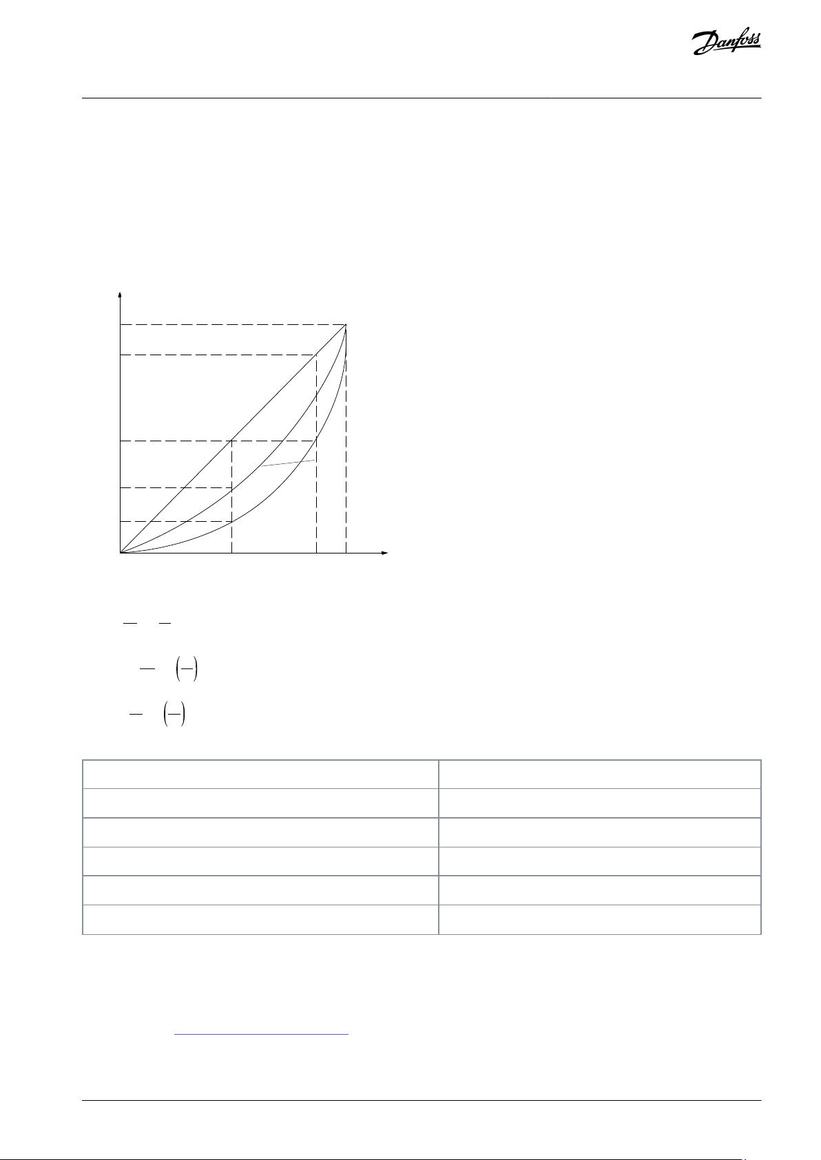
A drive takes advantage of the fact that centrifugal fans and pumps follow the laws of proportionality for such fans and pumps. For
further information, see 3.1.1.2 Example of Energy Savings.
3.1.1.1 The Clear Advantage - Energy Savings
The clear advantage of using a drive for controlling the speed of fans or pumps lies in the electricity savings.
When comparing with alternative control systems and technologies, a drive is the optimum energy control system for controlling
fan and pump systems.
Illustration 1: Fan Curves (A, B, and C) for Reduced Fan Volumes
Illustration 2: Energy Savings with Drive Solution
AJ363928382091en-000101 / 130R098314 | Danfoss A/S © 2021.04
Page 15
n
100%
50%
25%
12,5%
50% 100%
80%
80%
e75ha208.10
P o w er ~n
3
P r essur e ~n
2
Fl o w ~n
Q = Flow
P = Power
Q1 = Rated flow
P1 = Rated power
Q2 = Reduced flow
P2 = Reduced power
H = Pressure
n = Speed control
H1 = Rated pressure
n1 = Rated speed
H2 = Reduced pressure
n2 = Reduced speed
VLT® Flow Drive FC 111
Design Guide
Product Overview
When using a drive to reduce fan capacity to 60% - more than 50% energy savings may be obtained in typical applications.
3.1.1.2 Example of Energy Savings
As shown in the following illustration, the flow is controlled by changing the RPM. By reducing the speed by only 20% from the
rated speed, the flow is also reduced by 20%. This is because the flow is directly proportional to the RPM. The consumption of electricity, however, is reduced by 50%.
If the system in question only needs to be able to supply a flow that corresponds to 100% a few days in a year, while the average is
below 80% of the rated flow for the remainder of the year, the amount of energy saved is even more than 50%.
The following illustration describes the dependence of flow, pressure, and power consumption on RPM.
Illustration 3: Laws of Proportionally
Q
n
1
1
Flow:
Pressure:
Power:
Table 4: The Laws of Proportionality
=
Q
n
2
2
H
1
=
H
2
P
1
=
P
2
2
n
1
n
2
3
n
1
n
2
3.1.1.3 Comparison of Energy Savings
The Danfoss drive solution offers major savings compared with traditional energy saving solutions such as discharge damper solution and inlet guide vanes (IGV) solution. This is because the drive is able to control fan speed according to thermal load on the
system, and the drive has a built-in facility that enables the drive to function as a building management system, BMS.
The illustration in 3.1.1.2 Example of Energy Savings shows typical energy savings obtainable with 3 well-known solutions when fan
volume is reduced to 60%. As the graph shows, more than 50% energy savings can be achieved in typical applications.
AJ363928382091en-000101 / 130R0983 | 15Danfoss A/S © 2021.04
Page 16
e30ba782.10
1
2
3
4
5
1
Discharge damper
2
Less energy savings
3
Maximum energy savings
4
IGV5Costlier installation
e30ba779.12
0 60 0 60 0 60
0
20
40
60
80
100
Discharge Damper Solution
IGV Solution
VLT Solution
Energy consumed
Energy consumed
Energy consumed
Input power %
Volume %
VLT® Flow Drive FC 111
Design Guide
Product Overview
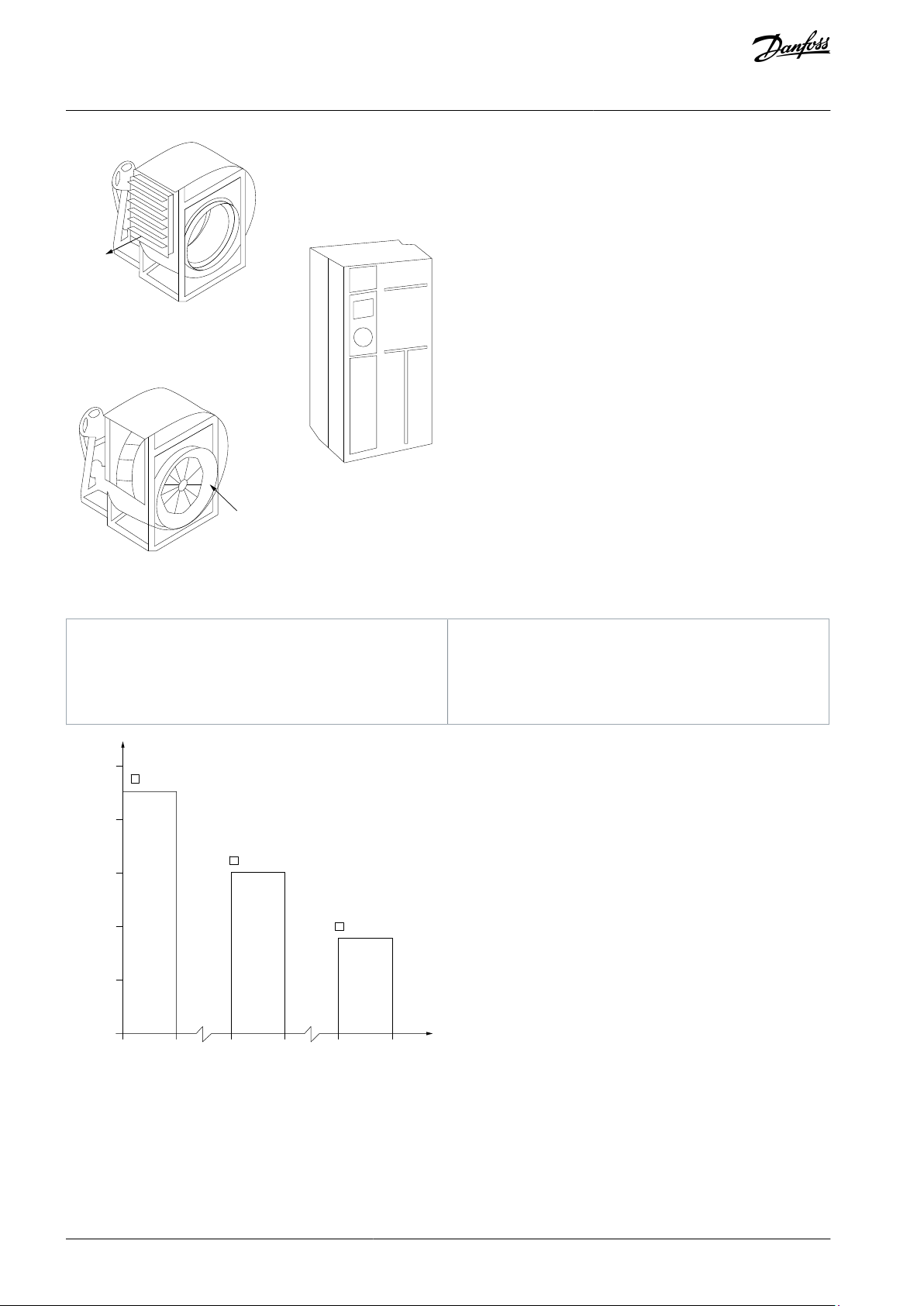
Illustration 4: The 3 Common Energy Saving Systems
Illustration 5: Energy Savings
Discharge dampers reduce power consumption. Inlet guide vanes offer a 40% reduction, but are expensive to install. The Danfoss
drive solution reduces energy consumption with more than 50% and is easy to install. It also reduces noise, mechanical stress, and
wear-and-tear, and extends the life span of the entire application.
AJ363928382091en-000101 / 130R098316 | Danfoss A/S © 2021.04
Page 17
500
[h]
t
1000
1500
2000
200100
300
[m3 /h]
400
Q
e75ha210.11
e75ha209.11
60
50
40
30
20
10
H
s
0
100
200 300 400
(m w g)
B
C
A
750r pm
1050r pm
1350r pm
1650r pm
0
10
20
30
(kW
)
40
50
60
200
100
300 ( m 3 /h )
( m
3
/h )
400
750r
pm
1050r pm
1350r pm
1650r pm
P
shaf
t
C
1
B
1
A
1
m3/h
Distribution
Valve regulation
Drive control
%
Hours
Power
Consumption
Power
Consumption
A1 - B
1
kWh
A1 - C
1
kWh
VLT® Flow Drive FC 111
Design Guide
Product Overview
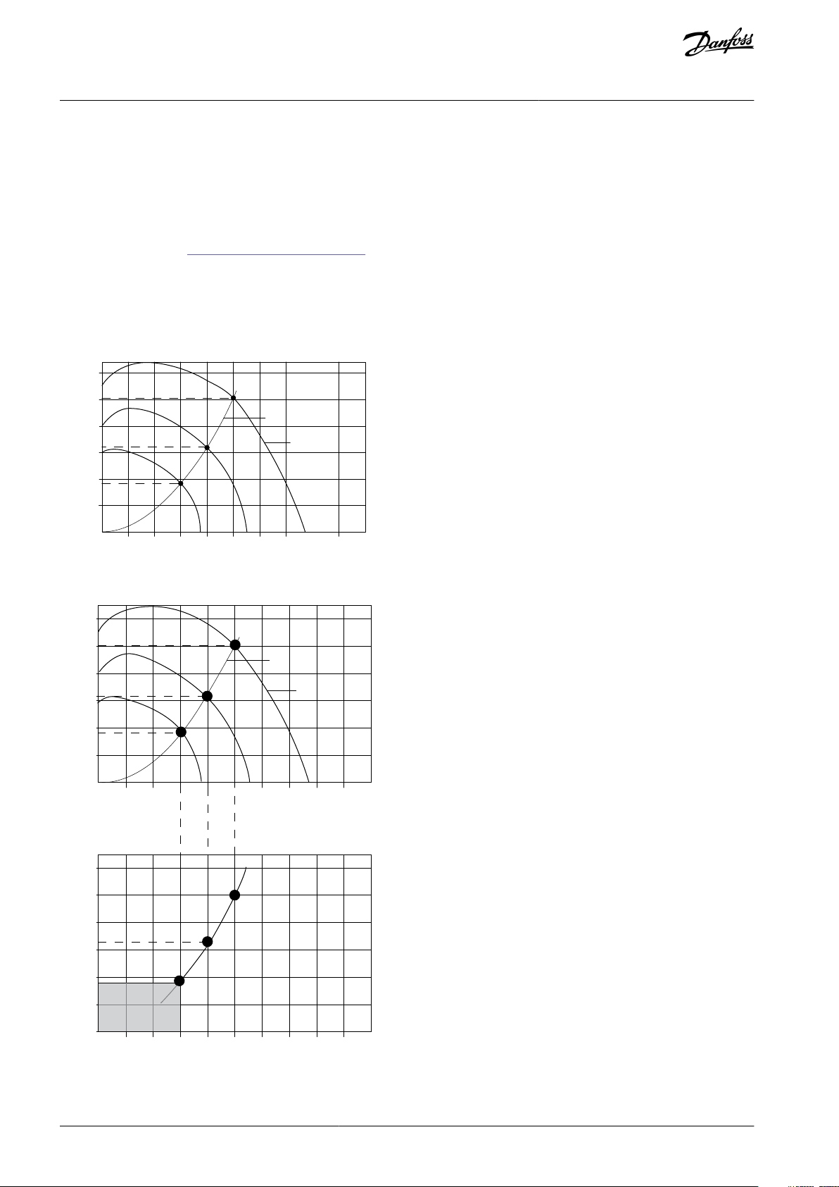
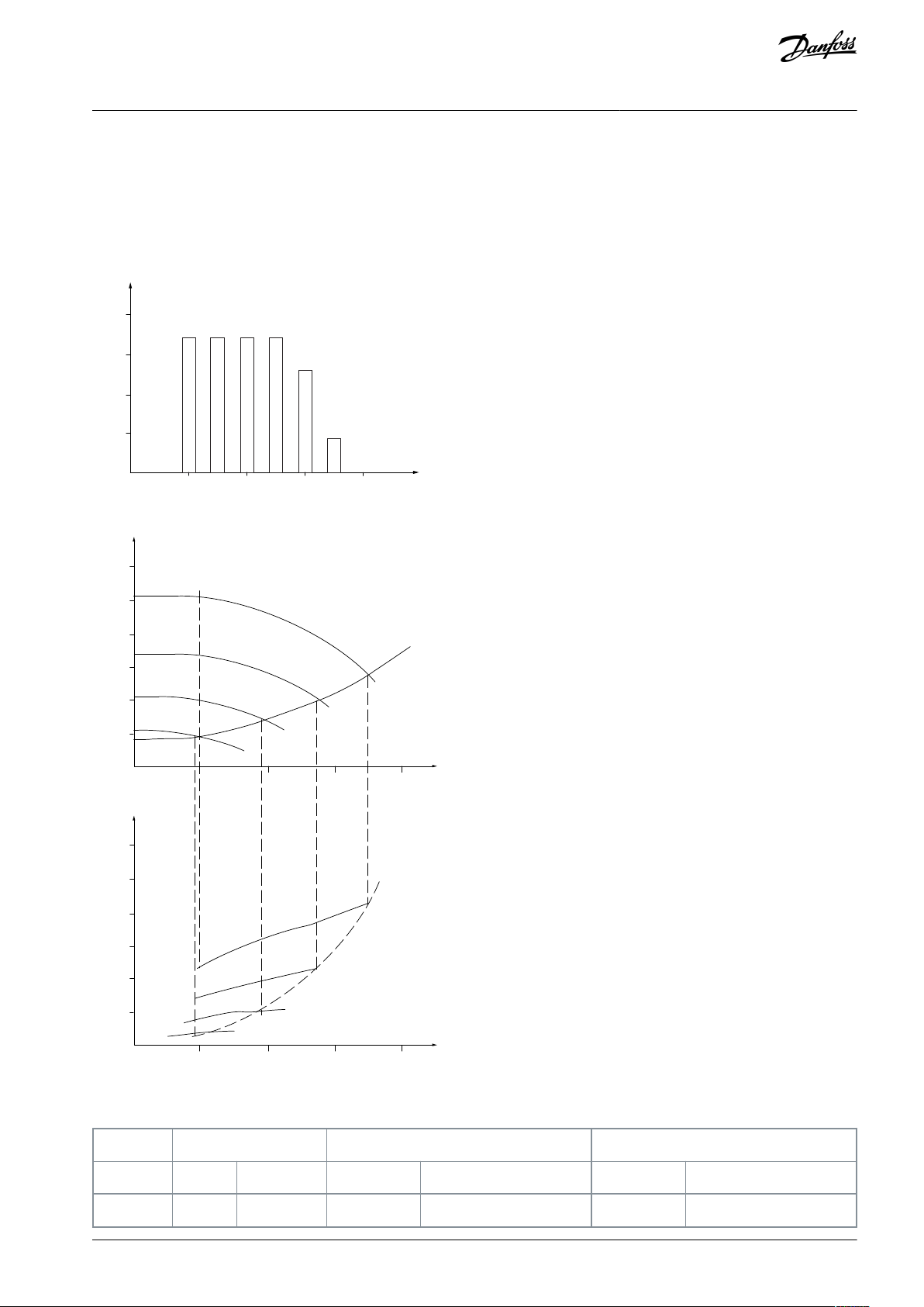
3.1.1.4 Example with Varying Flow over 1 Year
This example is calculated based on pump characteristics obtained from a pump datasheet. The result obtained shows energy savings of more than 50% at the given flow distribution over a year. The payback period depends on the price per kWh and the price of
drive. In this example, it is less than a year when compared with valves and constant speed.
Energy savings
P
= P
shaft
shaft output
Illustration 6: Flow Distribution over 1 Year
Illustration 7: Energy
Table 5: Result
AJ363928382091en-000101 / 130R0983 | 17Danfoss A/S © 2021.04
Page 18
3505438
42.5
18.615
42.5
18.615
300151314
38.5
50.589
29.0
38.106
250201752
35.0
61.320
18.5
32.412
200201752
31.5
55.188
11.5
20.148
150201752
28.0
49.056
6.5
11.388
100201752
23.0
40.296
3.5
6.132
Σ
100
8760–275.064
–
26.801
F ull load
% F ull load cur r en t
& speed
500
100
0
0
12,5 25 37,5 50H z
200
300
400
600
700
800
4
3
2
1
e75ha227.10
1
VLT® Flow Drive FC 111
2
Star/delta starter
3
Soft starter
4
Start directly on mains
VLT® Flow Drive FC 111
Design Guide
Product Overview
3.1.1.5 Better Control
If a drive is used for controlling the flow or pressure of a system, improved control is obtained.
A drive can vary the speed of the fan or pump, obtaining variable control of flow and pressure. Furthermore, a drive can quickly
adapt the speed of the fan or pump to new flow or pressure conditions in the system.
Simple control of process (flow, level, or pressure) utilizing the built-in PI control.
3.1.1.6 Star/Delta Starter or Soft Starter not Required
When larger motors are started, it is necessary in many countries to use equipment that limits the start-up current. In more traditional systems, a star/delta starter or soft starter is widely used. Such motor starters are not required if a drive is used.
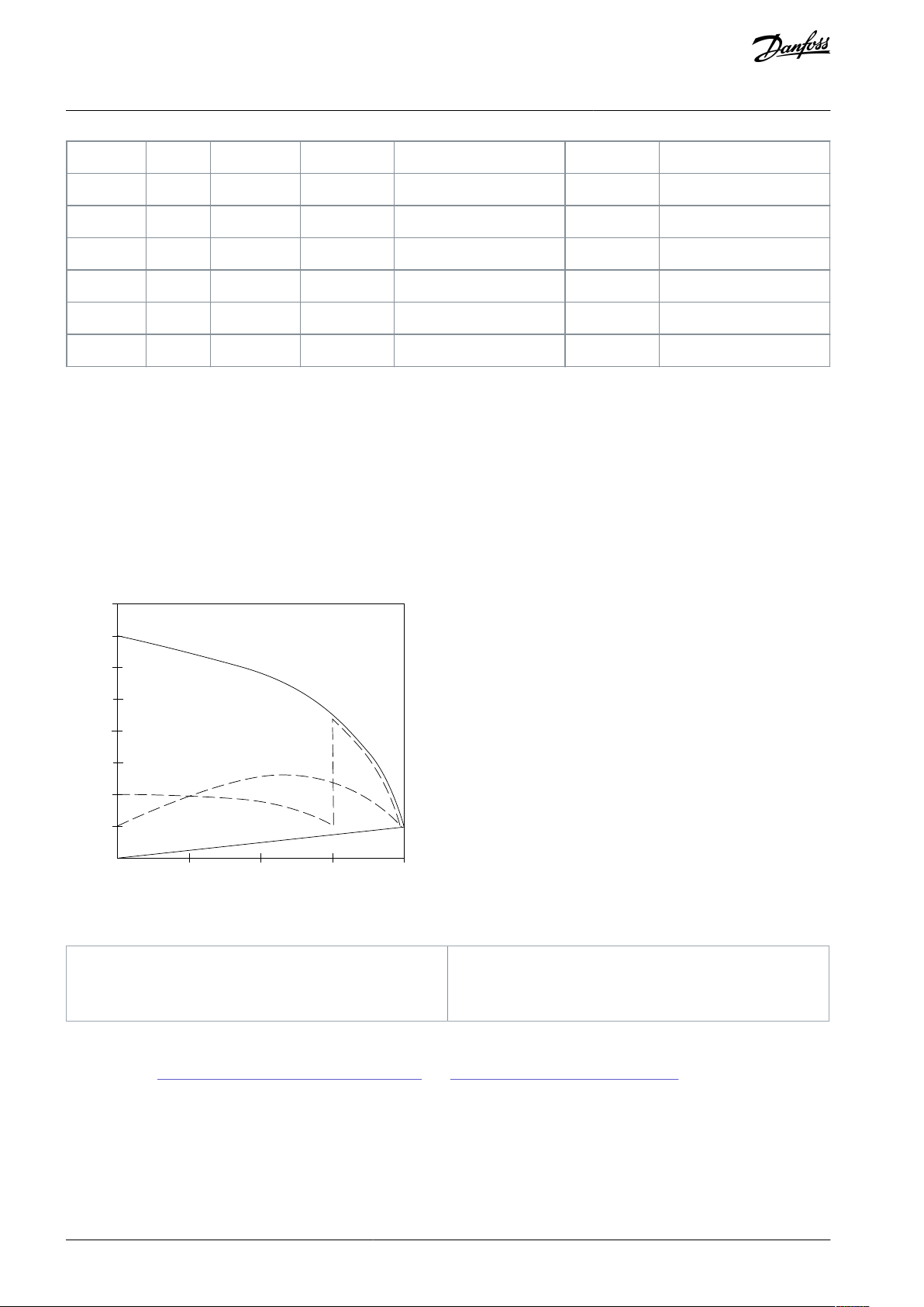
As shown in the following illustration, a drive does not consume more than rated current.
Illustration 8: Start-up Current
3.1.1.7 Using a Drive Saves Money
The example in 3.1.1.8 Traditional Fan System without a Drive and 3.1.1.9 Fan System Controlled by Drives shows that a drive replaces other equipment. It is possible to calculate the cost of installing the 2 different systems. In the example, the 2 systems can be
established at roughly the same price.
Use the VLT® Energy Box software that is introduced in chapter Additional Resources to calculate the cost savings that can be achieved by using a drive.
AJ363928382091en-000101 / 130R098318 | Danfoss A/S © 2021.04
Page 19
M
- +
M
M
x6 x6
x6
e75ha205.12
Valve
position
Starter
Fuses
LV
supply
P.F.C
Flow
3-Port
valve
Bypass
Return
Control
Supply
air
V.A.V
outlets
Duct
P.F.C
Mains
Fuses
Starter
Bypass
supply
LV
Return
valve
3-Port
Flow
Control
Valve
position
Starter
Power
Factor
Correction
Mains
IGV
Mechanical
linkage
and vanes
Fan
Motor
or
actuator
Main
B.M.S
Local
D.D.C.
control
Sensors
PT
Pressure
control
signal
0/10V
Temperature
control
signal
0/10V
Control
Mains
Cooling section Heating section
Fan sectionInlet guide vane
Pump Pump
D.D.C.
Direct digital control
E.M.S.
Energy management system
V.A.V.
Variable air volume
Sensor
P
Pressure
Sensor
T
Temperature
VLT® Flow Drive FC 111
Design Guide
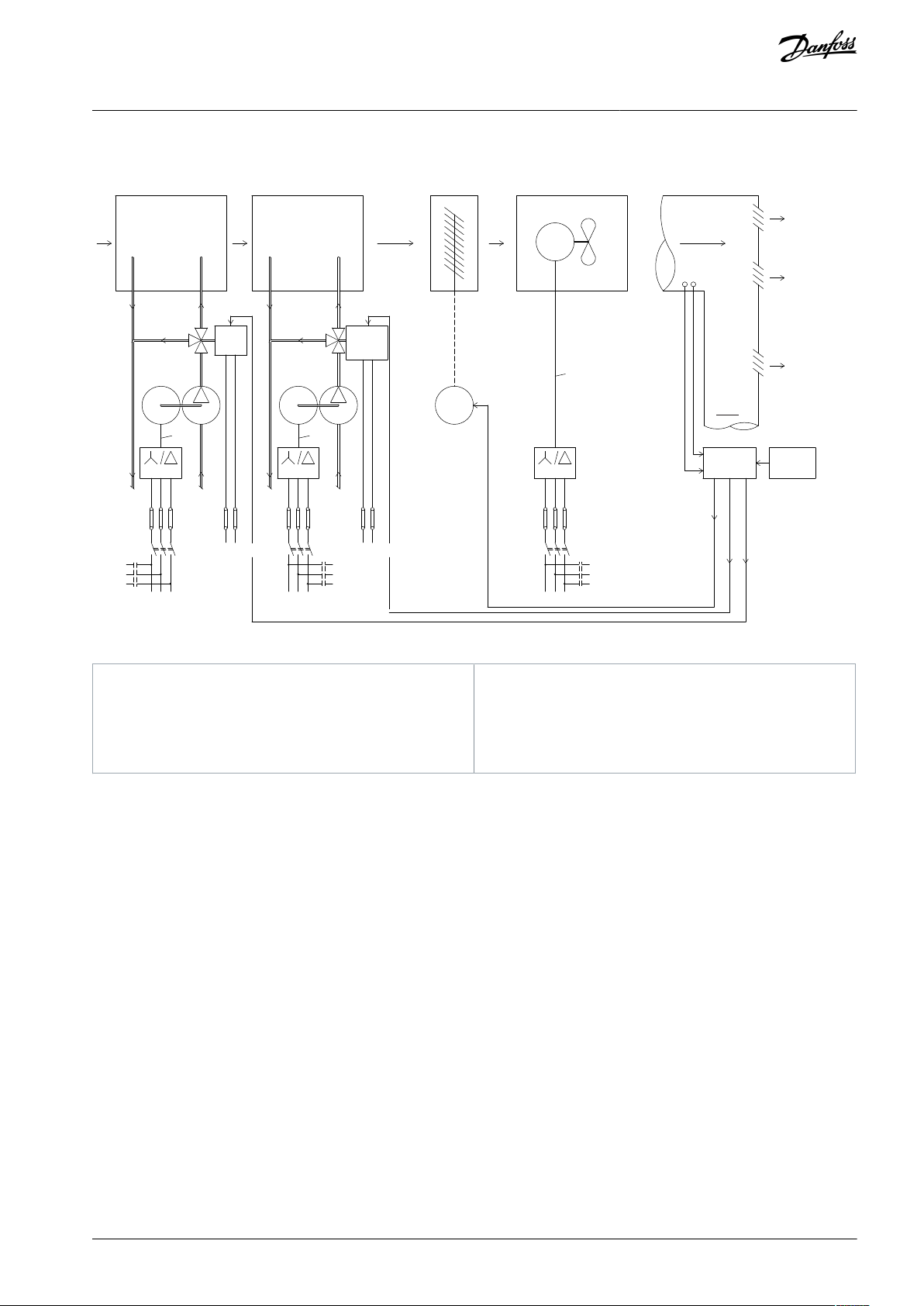
3.1.1.8 Traditional Fan System without a Drive
Product Overview
Illustration 9: Traditional Fan System without a Drive
AJ363928382091en-000101 / 130R0983 | 19Danfoss A/S © 2021.04
Page 20
e75ha206.11
Pump
Flow
Return
Supply
air
V.A.V
outlets
Duct
Mains
Pump
Return
Flow
Mains
Fan
Main
B.M.S
Local
D.D.C.
control
Sensors
Mains
Cooling section
Heating section
Fan section
Pressure
control
0-10V
or
0/4-20mA
Control
temperature
0-10V
or
0/4-20mA
Control
temperature
0-10V
or
0/4-20mA
VLT
M
- +
VLT
M
M
PT
VLT
x3 x3
x3
D.D.C.
Direct digital control
E.M.S.
Energy management system
V.A.V.
Variable air volume
Sensor
P
Pressure
Sensor
T
Temperature
VLT® Flow Drive FC 111
Design Guide
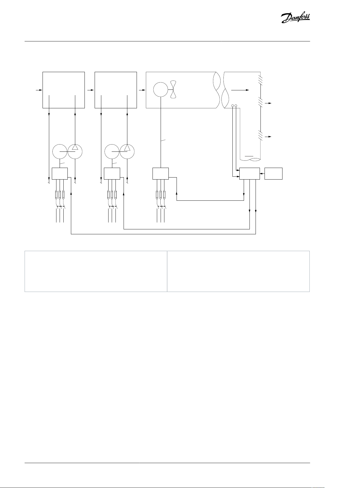
3.1.1.9 Fan System Controlled by Drives
Product Overview
Illustration 10: Fan System Controlled by Drives
3.1.2 Application Examples
The following sections give typical examples of applications.
3.1.2.1 Variable Air Volume
VAV or variable air volume systems, control both the ventilation and temperature to satisfy the requirements of a building. Central
VAV systems are considered to be the most energy efficient method to air condition buildings. By designing central systems instead
of distributed systems, a greater efficiency can be obtained.
The efficiency comes from utilizing larger fans and larger chillers which have much higher efficiencies than small motors and distributed air-cooled chillers. Savings are also seen from the decreased maintenance requirements.
The VLT Solution
While dampers and IGVs work to maintain a constant pressure in the ductwork, a drive solution saves much more energy and reduces the complexity of the installation. Instead of creating an artificial pressure drop or causing a decrease in fan efficiency, the
drive decreases the speed of the fan to provide the flow and pressure required by the system.
Centrifugal devices such as fans behave according to the centrifugal laws. This means that the fans decrease the pressure and flow
they produce as their speed is reduced. Their power consumption is thereby significantly reduced. The PI controller of the drive can
be used to eliminate the need for additional controllers.
AJ363928382091en-000101 / 130R098320 | Danfoss A/S © 2021.04
Page 21
D1
D2
D3
C
ooling c oil
Hea ting c oil
F
ilt
er
P r essur e
sig nal
Supply fan
V A V bo x es
Fl o w
Fl o w
P r essur e
tr ansmitt er
R etur n fan
3
3
T
e30bb455.10
Drive
Drive
VLT® Flow Drive FC 111
Design Guide
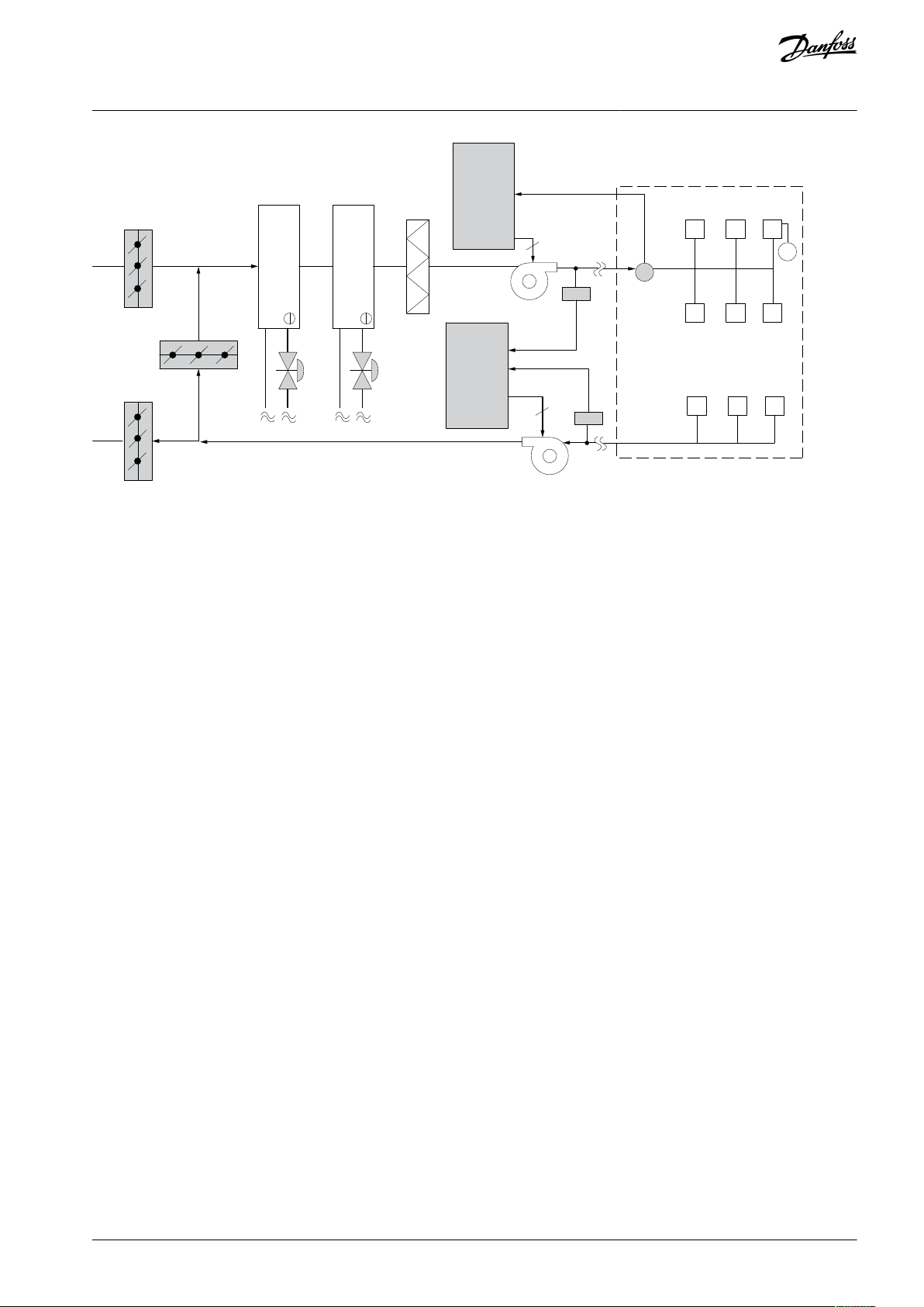
Illustration 11: Variable Air Volume
Product Overview
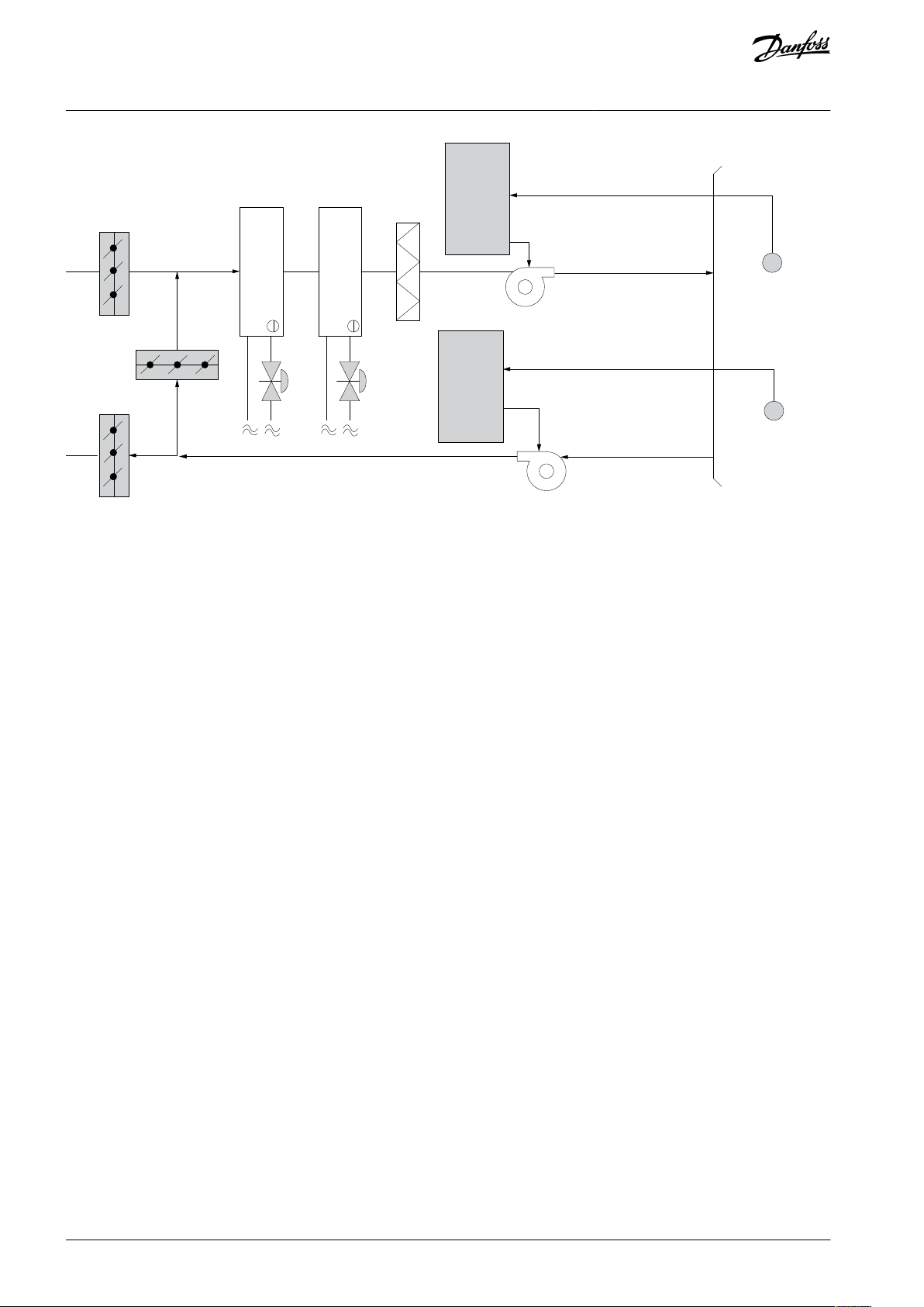
3.1.2.2 Constant Air Volume
CAV, or constant air volume systems, are central ventilation systems usually used to supply large common zones with the minimum
amounts of fresh tempered air. They preceded VAV systems and are therefore found in older multi-zoned commercial buildings as
well. These systems preheat amounts of fresh air utilizing air handling units (AHUs) with a heating coil, and many are also used to air
condition buildings and have a cooling coil. Fan coil units are frequently used to assist in the heating and cooling requirements in
the individual zones.
The VLT Solution
With a drive, significant energy savings can be obtained while maintaining decent control of the building. Temperature sensors or
CO2 sensors can be used as feedback signals to drives. Whether controlling temperature, air quality, or both, a CAV system can be
controlled to operate based on actual building conditions. As the number of people in the controlled area decreases, the need for
fresh air decreases. The CO2 sensor detects lower levels and decreases the supply fans speed. The return fan modulates to maintain
a static pressure setpoint or fixed difference between the supply and return airflows.
With temperature control, especially used in air conditioning systems, as the outside temperature varies as well as the number of
people in the controlled zone changes, different cooling requirements exist. As the temperature decreases below the setpoint, the
supply fan can decrease its speed. The return fan modulates to maintain a static pressure setpoint. By decreasing the air flow, energy used to heat or cool the fresh air is also reduced, adding further savings.
Several features of the Danfoss dedicated drive can be utilized to improve the performance of the CAV system. One concern of
controlling a ventilation system is poor air quality. The programmable minimum frequency can be set to maintain a minimum
amount of supply air regardless of the feedback or reference signal. The drive also includes a PI controller, which allows monitoring
both temperature and air quality. Even if the temperature requirement is fulfilled, the drive maintains enough supply air to satisfy
the air quality sensor. The controller is capable of monitoring and comparing 2 feedback signals to control the return fan by maintaining a fixed differential airflow between the supply and return ducts as well.
AJ363928382091en-000101 / 130R0983 | 21Danfoss A/S © 2021.04
Page 22
P r essur e
sig nal
C ooling c oil
Hea ting c oil
D1
D2
D3
F ilt er
P r essur e
tr ansmitt er
Supply fan
R etur n fan
T emper a tur e
sig nal
T emper a tur e
tr ansmitt er
e30bb451.10
Drive
Drive
VLT® Flow Drive FC 111
Design Guide
Illustration 12: Constant Air Volume
Product Overview
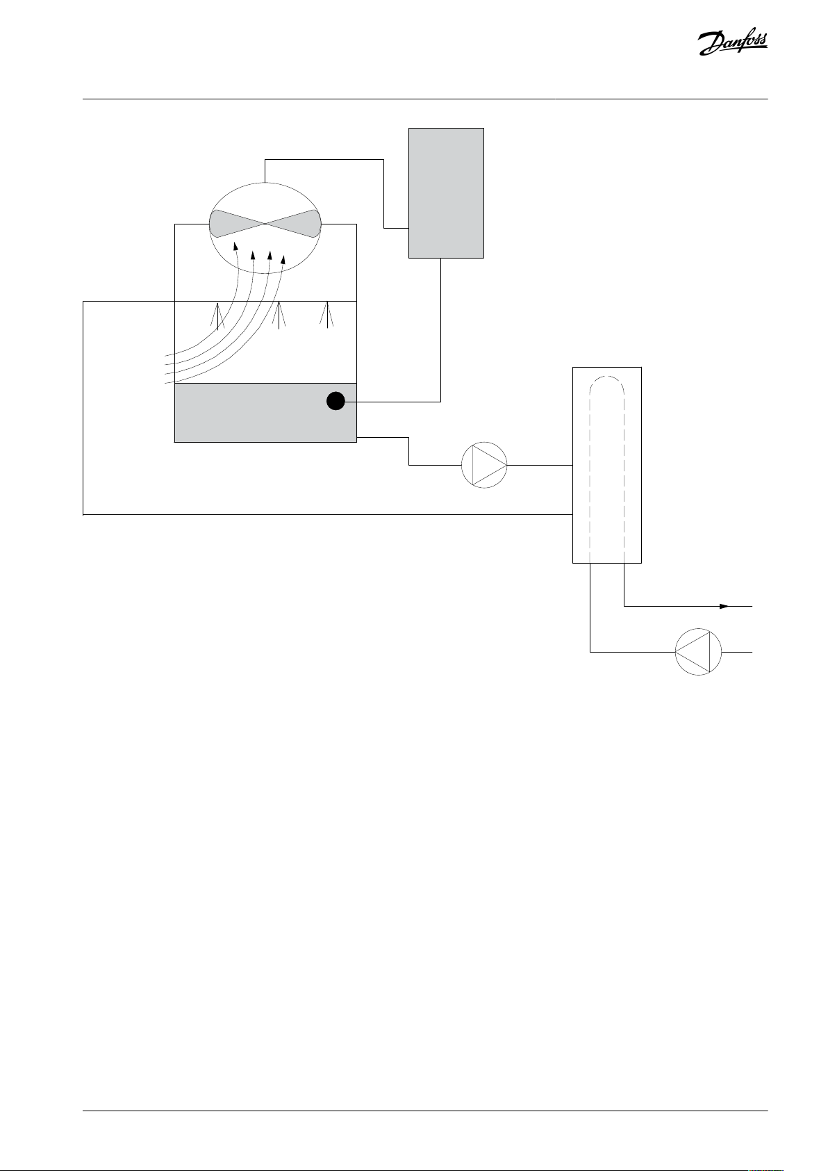
3.1.2.3 Cooling Tower Fan
Cooling tower fans cool condenser-water in water-cooled chiller systems. Water-cooled chillers provide the most efficient means of
creating chilled water. They are as much as 20% more efficient than air cooled chillers. Depending on climate, cooling towers are
often the most energy efficient method of cooling the condenser-water from chillers.
They cool the condenser water by evaporation. The condenser water is sprayed into the cooling tower until the cooling towers fill to
increase its surface area. The tower fan blows air through the fill and sprayed water to aid in the evaporation. Evaporation removes
energy from the water dropping its temperature. The cooled water collects in the cooling towers basin where it is pumped back
into the chillers condenser and the cycle is repeated.
The VLT Solution
With a drive, the cooling towers fans can be controlled to the required speed to maintain the condenser-water temperature. The
drives can also be used to turn the fan on and off as needed.
Several features of the Danfoss dedicated drive can be utilized to improve the performance of cooling tower fans applications. As
the cooling tower fans drop below a certain speed, the effect the fan has on cooling the water becomes small. Also, when utilizing a
gearbox to frequency control the tower fan, a minimum speed of 40–50% is required.
The customer programmable minimum frequency setting is available to maintain this minimum frequency even as the feedback or
speed reference calls for lower speeds.
Also as a standard feature, the drive can be programmed to enter a sleep mode and stop the fan until a higher speed is required.
Additionally, some cooling tower fans have undesirable frequencies that may cause vibrations. These frequencies can easily be avoided by programming the bypass frequency ranges in the drive.
AJ363928382091en-000101 / 130R098322 | Danfoss A/S © 2021.04
Page 23
W a t er I nlet
W a t er Outlet
CHILLER
T emper a tur e
S ensor
BASIN
C onderser
W a t er pump
Supply
e30bb453.10
Drive
VLT® Flow Drive FC 111
Design Guide
Product Overview
Illustration 13: Cooling Tower Fan
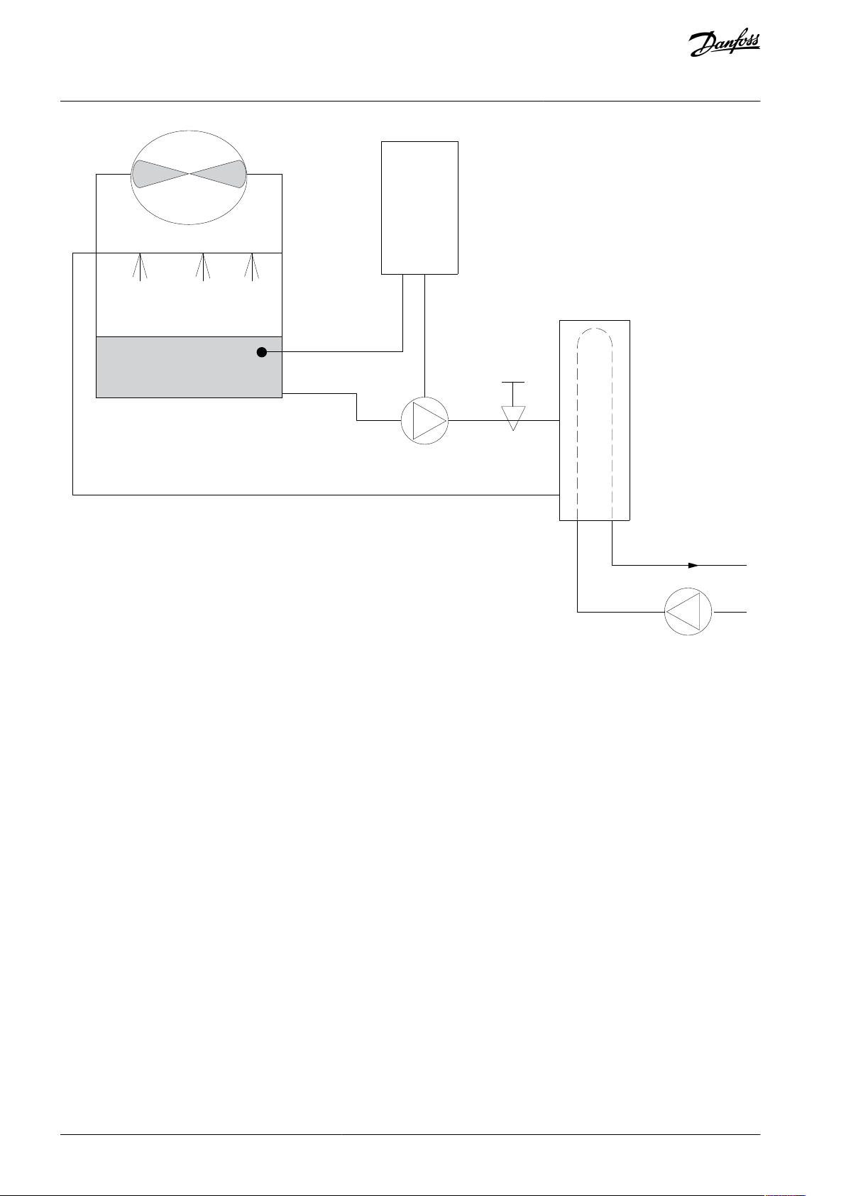
3.1.2.4 Condenser Pumps
Condenser water pumps are primarily used to circulate water through the condenser section of water cooled chillers and their associated cooling tower. The condenser water absorbs the heat from the chiller's condenser section and releases it into the atmosphere
in the cooling tower. These systems are used to provide the most efficient means of creating chilled water, they are as much as 20%
more efficient than air cooled chillers.
The VLT Solution
Drives can be added to condenser water pumps instead of balancing the pumps with a throttling valve or trimming the pump impeller.
Using a drive instead of a throttling valve simply saves the energy that would have been absorbed by the valve. This can amount to
savings of 15–20% or more. Trimming the pump impeller is irreversible, thus if the conditions change and higher flow is required
the impeller must be replaced.
AJ363928382091en-000101 / 130R0983 | 23Danfoss A/S © 2021.04
Page 24
Wa t e
r
I
nlet
Wa
t e
r
Outlet
BASIN
F
lo w or pr essur
e sensor
C ondenser
W a t er pump
T hr ottling
v alv e
Supply
CHILLER
e30bb452.10
Drive
VLT® Flow Drive FC 111
Design Guide
Product Overview
Illustration 14: Condenser Pumps
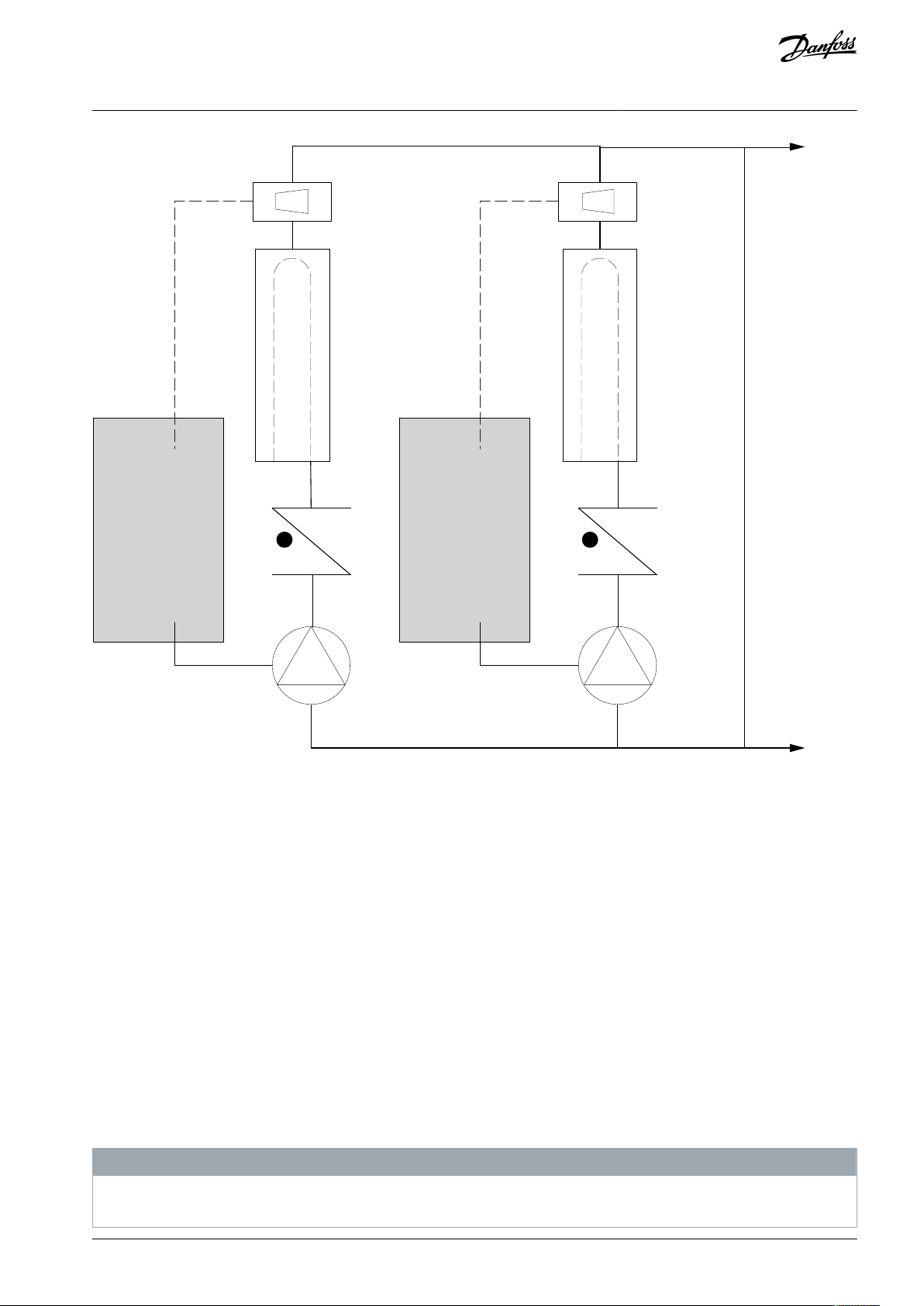
3.1.2.5 Primary Pumps
Primary pumps in a primary/secondary pumping system can be used to maintain a constant flow through devices that encounter
operation or control difficulties when exposed to variable flow. The primary/secondary pumping technique decouples the primary
production loop from the secondary distribution loop. This allows devices such as chillers to obtain constant design flow and operate properly while allowing the rest of the system to vary in flow.
As the evaporator flow rate decreases in a chiller, the chilled water begins to become overchilled. As this happens, the chiller attempts to decrease its cooling capacity. If the flow rate drops far enough, or too quickly, the chiller cannot shed its load sufficiently
and the chiller’s safety trips the chiller requiring a manual reset. This situation is common in large installations especially when 2 or
more chillers in parallel are installed if primary/ secondary pumping is not utilized.
The VLT Solution
Depending on the size of the system and the size of the primary loop, the energy consumption of the primary loop can become
substantial.
A drive can be added to the primary system to replace the throttling valve and/or trimming of the impellers, leading to reduced
operating expenses. 2 control methods are common:
Flow meter
Because the desired flow rate is known and is constant, a flow meter installed at the discharge of each chiller, can be used to control
the pump directly. Using the built-in PI controller, the drive always maintains the appropriate flow rate, even compensating for the
changing resistance in the primary piping loop as chillers and their pumps are staged on and off.
Local speed determination
The operator simply decreases the output frequency until the design flow rate is achieved.
Using a drive to decrease the pump speed is very similar to trimming the pump impeller, except it does not require any labor, and
the pump efficiency remains higher. The balancing contractor simply decreases the speed of the pump until the proper flow rate is
achieved and leaves the speed fixed. The pump operates at this speed any time the chiller is staged on. Because the primary loop
does not have control valves or other devices that can cause the system curve to change, and the variance due to staging pumps
and chillers on and off is usually small, this fixed speed remains appropriate. If the flow rate needs to be increased later in the system’s life, the drive can simply increase the pump speed instead of requiring a new pump impeller.
AJ363928382091en-000101 / 130R098324 | Danfoss A/S © 2021.04
Page 25
CHILLER
CHILLER
F
lo
wmet er
F lo wmet er
F F
e30bb456.10
Drive
Drive
VLT® Flow Drive FC 111
Design Guide
Product Overview
Illustration 15: Primary Pumps
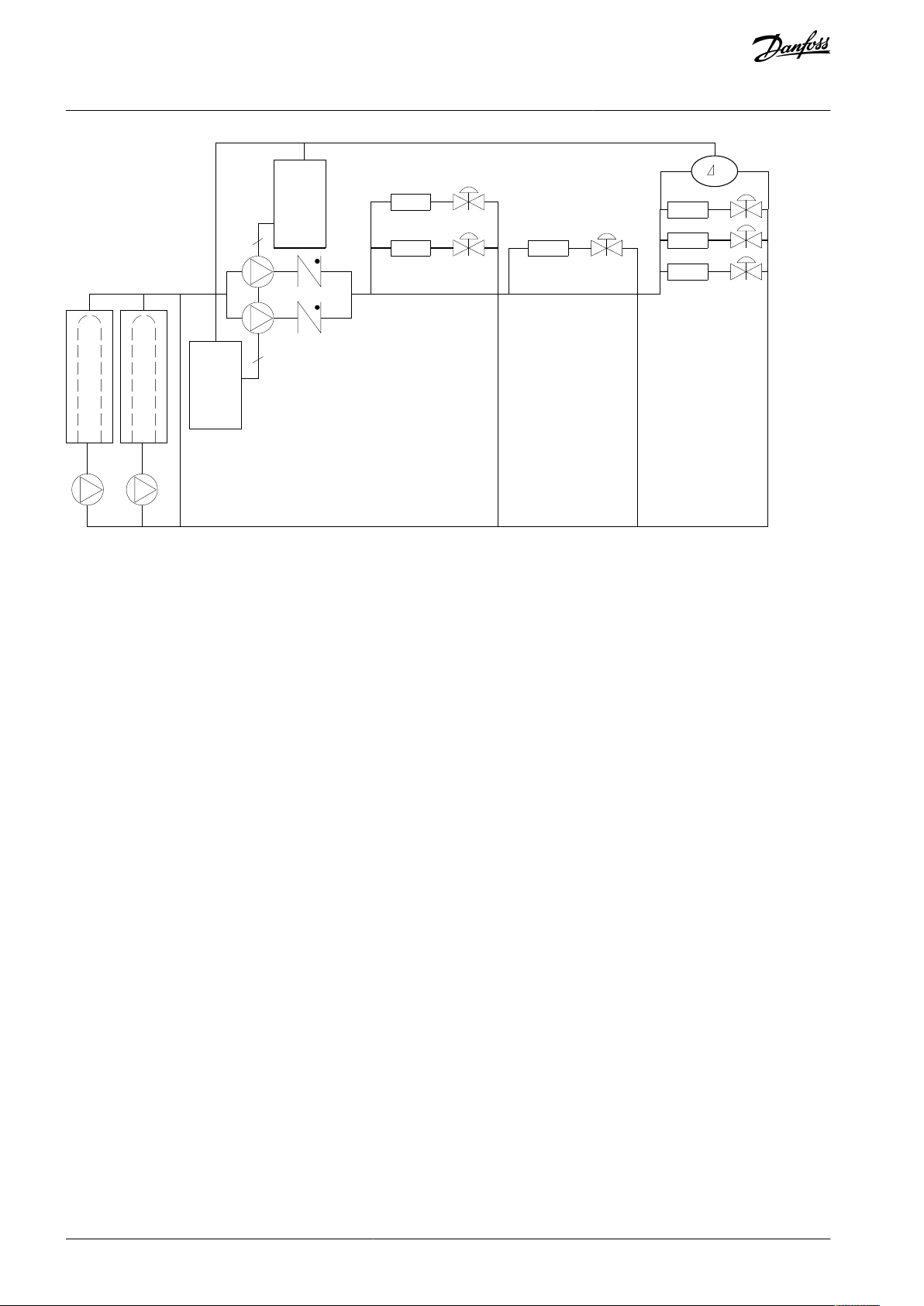
3.1.2.6 Secondary Pumps
Secondary pumps in a primary/secondary chilled water pumping system distribute the chilled water to the loads from the primary
production loop. The primary/secondary pumping system is used to hydronically de-couple 1 piping loop from another. In this case,
the primary pump is used to maintain a constant flow through the chillers while allowing the secondary pumps to vary in flow,
increase control and save energy.
If the primary/secondary concept is not used in the design of a variable volume system when the flow rate drops far enough or too
quickly, the chiller cannot shed its load properly. The chiller’s low evaporator temperature safety then trips the chiller requiring a
manual reset. This situation is common in large installations especially when 2 or more chillers in parallel are installed.
The VLT Solution
While the primary-secondary system with 2-way valves improves energy savings and eases system control problems, the true energy savings and control potential is realized by adding drives.
With the proper sensor location, the addition of drives allows the pumps to vary their speed to follow the system curve instead of
the pump curve. This results in the elimination of wasted energy and eliminates most of the overpressurization that 2-way valves
can be subjected to.
As the monitored loads are reached, the 2-way valves close down. This increases the differential pressure measured across the load
and the 2-way valve. As this differential pressure starts to rise, the pump is slowed to maintain the control head also called setpoint
value. This setpoint value is calculated by summing the pressure drop of the load and the 2-way valve together under design conditions.
N O T I C E
When running multiple pumps in parallel, they must run at the same speed to maximize energy savings, either with individual
dedicated drives or 1 drive running multiple pumps in parallel.
AJ363928382091en-000101 / 130R0983 | 25Danfoss A/S © 2021.04
Page 26
CHILLER
CHILLER
3
3
P
e30bb454.10
Drive
Drive
VLT® Flow Drive FC 111
Design Guide
Product Overview
Illustration 16: Secondary Pumps
3.1.3 Check Valve Monitoring
In the pump application system, a damaged check valve is hard to detect, which therefore causes low efficiency of the whole system. VLT® Flow Drive FC 111 has the ability to monitor the status of check valves in the system. After enabling the check valve monitoring function via setting the parameter 22-04 Check Valve Monitor to [1] Enabled, once a damaged check valve is detected, the
drive trips warning 159, Check Valve Failure.
3.1.4 Dry Pump Detection
In the pump application system, the drive monitors the operation status of the system to detect whether there is water on pump's
suction side. If the pump runs at maximum speed and consumes little power, then it can be assumed that there is no water on the
pump's suction side. Via setting the parameter 22-26 Dry Pump Function to warning or alarm, once the dry pump condition is detected, the drive trips warning/alarm 93, dry pump.
3.1.5 End of Curve Detection
In the pump application system, the drive monitors the operation status of the system to detect whether the pressure side of pump
is subject to a major leakage. If the pump runs at maximum speed for a defined time period, but the pressure is below the set point,
then it can be considered to reflect the end of curve situation. Via setting the parameter 22-50 End of Curve Function to warning or
alarm, once the end of curve condition is detected, the drive trips warning/alarm 94, end of curve.
3.1.6 Time-based Functions
In some application scenarios, there are requirements to control the motor running for a specific time, in a specific direction and a
specific speed within a specific time interval. For example, checking the motor status in fire mode or exercising pumps, fans, and
compressors.
For detailed parameter settings, refer to the parameter group 23-** Time-based Functions in the drive's Programming Guide.
3.2 Control Structures
3.2.1 Introduction
There are two control modes for the drive:
Open loop.
•
Closed loop.
•
Select [0] Open loop or [1] Closed loop in parameter 1-00 Configuration Mode.
AJ363928382091en-000101 / 130R098326 | Danfoss A/S © 2021.04
Page 27

100%
0%
-100%
100%
A ut o mode
Hand mode
L ocal
P 4-10
M ot or speed
dir ec tion
P 4-14
M ot or speed
high limit [H z]
P 4-12
M ot or speed
lo w limit [H z]
Reference
handling
Remote
reference
Local
reference
scaled to
Hz
LCP Hand on,
off and auto
on keys
Remote
Reference
P 3-4* Ramp 1
P 3-5* Ramp 2
Ramp
To motor
control
e30bb892.11
Hand
On
On
e30bb893.11
Off Auto
Reset
VLT® Flow Drive FC 111
Design Guide
Product Overview
3.2.2 Control Structure Open Loop
Illustration 17: Open-loop Structure
In the configuration shown in the above illustration, parameter 1-00 Configuration Mode is set to [0] Open loop. The resulting reference from the reference handling system or the local reference is received and fed through the ramp limitation and speed limitation
before being sent to the motor control. The output from the motor control is then limited by the maximum frequency limit.
3.2.3 PM/EC+ Motor Control
The Danfoss EC+ concept provides the possibility for using high-efficient PM motors (permanent magnet motors) in IEC standard
enclosure sizes operated by Danfoss drives.
The commissioning procedure is comparable to the existing one for asynchronous (induction) motors by utilizing the Danfoss VVC
PM control strategy.
Customer advantages:
•
Free choice of motor technology (permanent magnet or induction motor).
•
Installation and operation as know on induction motors.
•
Manufacturer independent when selecting system components (for example, motors).
•
Best system efficiency by selecting best components.
•
Possible retrofit of existing installations.
•
Power range: 0.37–90 kW (0.5–121 hp) (400 V) for induction motors and 0.37–22 kW (0.5–30 hp) (400 V) for PM motors.
Current limitations for PM motors:
•
Currently only supported up to 22 kW (30 hp).
•
LC filters are not supported with PM motors.
•
Kinetic back-up algorithm is not supported with PM motors.
•
Support only complete AMA of the stator resistance Rs in the system.
•
No stall detection (supported from software version 62.80).
3.2.4 Local (Hand On) and Remote (Auto On) Control
The drive can be operated manually via the local control panel (LCP) or remotely via analog/digital inputs or serial bus. If allowed in
parameter 0-40 [Hand on] Key on LCP, parameter 0-44 [Off/Reset] Key on LCP, and parameter 0-42 [Auto on] Key on LCP, it is possible to
start and stop the drive via LCP by pressing [Hand On] and [Off/Reset]. Alarms can be reset via the [Off/Reset] key.
+
Illustration 18: LCP Keys
Local reference forces the configuration mode to open loop, independent on the setting of parameter 1-00 Configuration Mode.
AJ363928382091en-000101 / 130R0983 | 27Danfoss A/S © 2021.04
Page 28
7-30 PI
Nor mal/I n v erse
C on tr ol
PI
F eedback
P 4-10
M ot or speed
dir ec tion
T o mot or
c on tr ol
e30bb894.11
S
100%
0%
-100%
100%
*[-1]
_
+
Reference
Scale to
speed
e30bb895.10
+
-
PI
P
P
P
Ref.
signal
Desired
flow
FB conversion
Ref.
FB
Flow
FB
signal
Flow
P 20-01
VLT® Flow Drive FC 111
Design Guide
Product Overview
Local reference is restored at power-down.
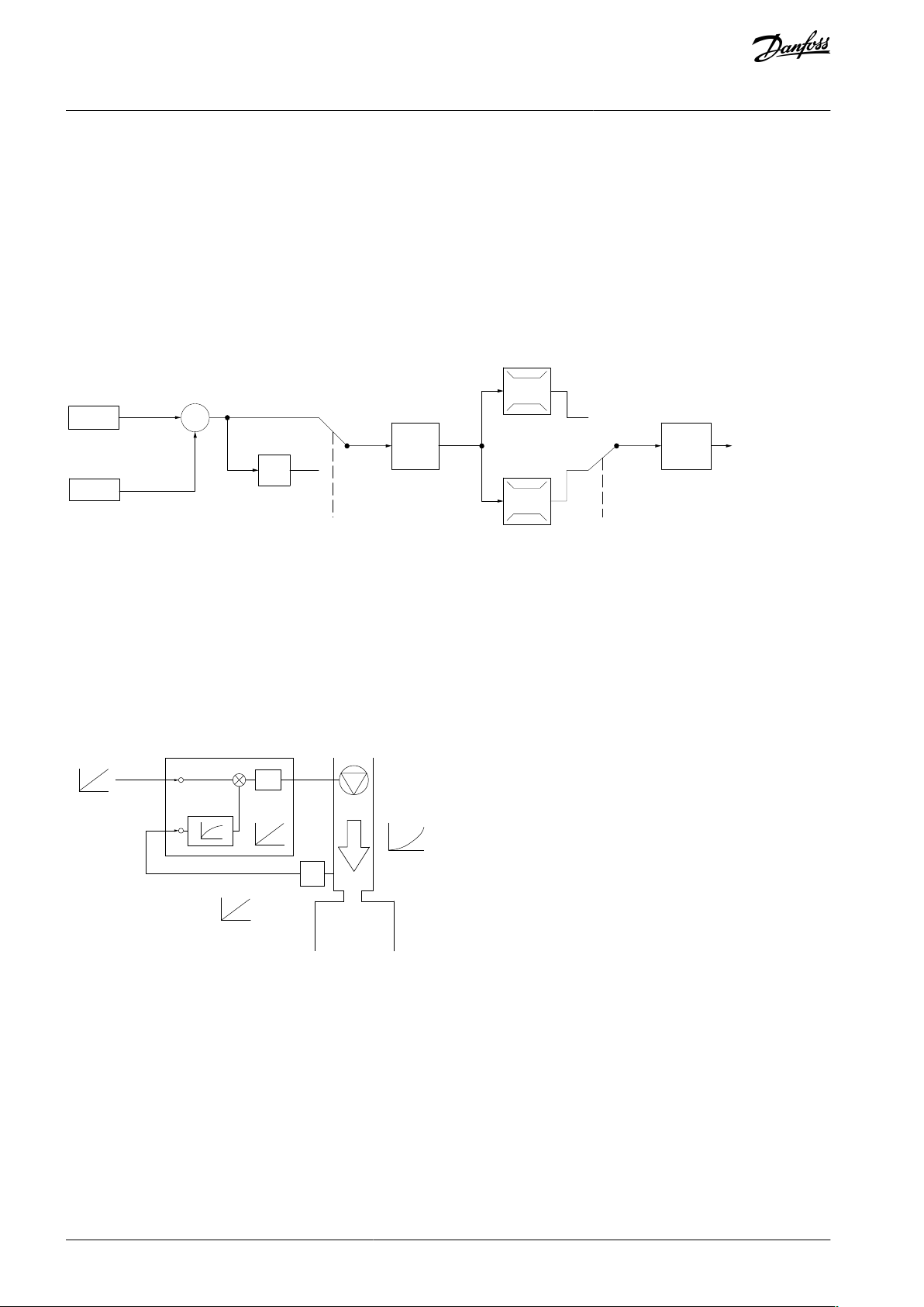
3.2.5 Control Structure Closed Loop
The internal controller allows the drive to become a part of the controlled system. The drive receives a feedback signal from a sensor
in the system. It then compares this feedback to a setpoint reference value and determines the error, if any, between these 2 signals.
It then adjusts the speed of the motor to correct this error.
For example, consider a compressor application where the speed of the compressor is to be controlled to ensure a constant suction
pressure in an evaporator. The suction pressure value is supplied to the drive as the setpoint reference. A pressure sensor measures
the actual suction pressure in the evaporator and supplies the data to the drive as a feedback signal. If the feedback signal is greater
than the setpoint reference, the drive speeds up the compressor to reduce the pressure. In a similar way, if the suction pressure is
lower than the setpoint reference, the drive automatically slows down the compressor to increase the pressure.
Illustration 19: Control Structure Closed Loop
While the default values for the closed-loop controller of the drive often provide satisfactory performance, the control of the system
can often be optimized by adjusting parameters.
3.2.6 Feedback Conversion
In some applications, it may be useful to convert the feedback signal. One example of this is using a pressure signal to provide flow
feedback. Since the square root of pressure is proportional to flow, the square root of the pressure signal yields a value proportional
to the flow. See the following illustration.
Illustration 20: Feedback Signal Conversion
3.2.7 Reference Handling
Details for open-loop and closed-loop operation.
AJ363928382091en-000101 / 130R098328 | Danfoss A/S © 2021.04
Page 29
Speed open
loop
mode
Input command:
freeze reference
Process
control
Scale to
Hz
Scale to
process
unit
Remote
reference/
setpoint
±200%
Feedback
handling
Remote
reference in %
maxRefPCT
minRefPct
min-max ref
Freeze
reference &
increase/
decrease
reference
±100%
Input commands:
Speed up/speed down
±200%
Relative
reference
=
X+X*Y/100
±200%
External reference in %
±200%
Parameter choise:
Reference resource 1,2,3
±100%
Preset reference
Input command:
preset ref bit0, bit1, bit2
+
+
Relative scalling reference
Intern resource
Preset relative reference
±100%
Preset reference 0 ±100%
Preset reference 1 ±100%
Preset reference 2 ±100%
Preset reference 3 ±100%
Preset reference 4 ±100%
Preset reference 5 ±100%
Preset reference 6 ±100%
Preset reference 7 ±100%
External resource 1
No function
Analog reference
±200 %
Local bus reference
±200 %
Pulse input reference
±200 %
Pulse input reference
±200 %
Pulse input reference
±200 %
External resource 2
No function
Analog reference
±200 %
Local bus reference
±200 %
External resource 3
No function
Analog reference
±200 %
Local bus reference
±200 %
Y
X
e30be842.10
VLT® Flow Drive FC 111
Design Guide
Product Overview
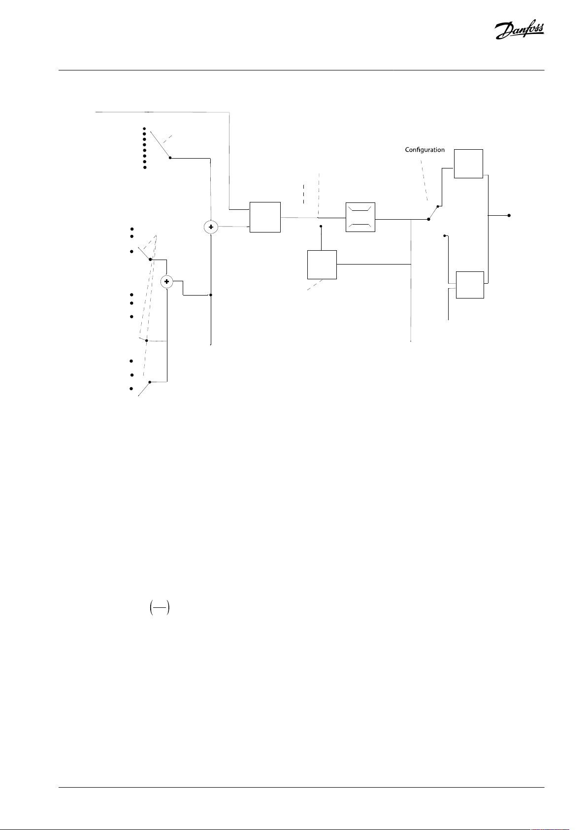
Illustration 21: Block Diagram Showing Remote Reference
The remote reference consists of:
•
Preset references.
•
External references (analog inputs and serial communication bus references).
•
The preset relative reference.
•
Feedback-controlled setpoint.
Up to 8 preset references can be programmed in the drive. The active preset reference can be selected using digital inputs or the
serial communications bus. The reference can also be supplied externally, most commonly from an analog input. This external
source is selected by 1 of the 3 reference source parameters (parameter 3-15 Reference 1 Source, parameter 3-16 Reference 2 Source,
and parameter 3-17 Reference 3 Source). All reference resources and the bus reference are added to produce the total external reference. The external reference, the preset reference, or the sum of the 2 can be selected to be the active reference. Finally, this reference can by be scaled using parameter 3-14 Preset Relative Reference.
The scaled reference is calculated as follows:
Reference = X + X ×
Where X is the external reference, the preset reference or the sum of these and Y is parameter 3-14 Preset Relative Reference in [%].
If Y, parameter 3-14 Preset Relative Reference, is set to 0%, the reference is not affected by the scaling.
3.2.8 Tuning the Drive Closed-loop
Once the drive's closed-loop controller has been set up, test the performance of the controller. Often, its performance may be acceptable using the default values of parameter 20-93 PI Proportional Gain and parameter 20-94 PI Integral Time. However, sometimes
it may be helpful to optimize these parameter values to provide faster system response while still controlling speed overshoot.
3.2.9 Adjusting the Manual PI
Procedure
1.
Start the motor.
100
Y
AJ363928382091en-000101 / 130R0983 | 29Danfoss A/S © 2021.04
Page 30

Enclosure size
Level [dBA]
(1)
H1
43.6H250.2H353.8H464H563.7H671.5H767.5 (75 kW (100 hp) 71.5 dB)
H8
73.5
H1373H14
75
VLT® Flow Drive FC 111
Design Guide
2.
Set parameter 20-93 PI Proportional Gain to 0.3 and increase it until the feedback signal begins to oscillate. If necessary, start
and stop the drive or make step changes in the setpoint reference to attempt to cause oscillation.
3.
Reduce the PI proportional gain until the feedback signal stabilizes.
4.
Reduce the proportional gain by 40–60%.
5.
Set parameter 20-94 PI Integral Time to 20 s and reduce it until the feedback signal begins to oscillate. If necessary, start and
stop the drive or make step changes in the setpoint reference to attempt to cause oscillation.
Increase the PI integral time until the feedback signal stabilizes.
6.
Increase the integral time by 15–50%.
7.
Product Overview
3.3 Ambient Running Conditions
3.3.1 Air Humidity
The drive has been designed to meet the IEC/EN 60068-2-3 standard, EN 50178 9.4.2.2 at 50 °C (122 °F).
3.3.2 Acoustic Noise or Vibration
If the motor or the equipment driven by the motor - for example, a fan - makes noise or vibrations at certain frequencies, configure
the following parameters or parameter groups to reduce or eliminate the noise or vibrations:
•
Parameter group 4-6* Speed Bypass.
•
Set parameter 14-03 Overmodulation to [0] Off.
•
Switching pattern and switching frequency parameter group 14-0* Inverter Switching.
•
Parameter 1-64 Resonance Dampening.
3.3.2.1 Acoustic Noise
The acoustic noise from the drive comes from 3 sources:
DC-link coils.
•
Integral fan.
•
RFI filter choke.
•
Table 6: Typical Values Measured at a Distance of 1 m (3.28 ft) from the Unit
1
The values are measured under the background of 35 dBA noise and the fan running with full speed.
AJ363928382091en-000101 / 130R098330 | Danfoss A/S © 2021.04
Page 31

VLT® Flow Drive FC 111
Design Guide
Product Overview
3.3.2.2 Vibration and Shock
The drive has been tested according to the following standards:
•
IEC/EN 60068-2-6: Vibration (sinusoidal) - 1970
•
IEC/EN 60068-2-64: Vibration, broad-band random
The drive complies with the requirements that exist for units mounted on the walls and floors of production premises, and in panels
bolted to walls or floors.
3.3.3 Aggressive Environments
A drive contains many mechanical and electronic components. All are to some extent vulnerable to environmental effects.
C A U T I O N
INSTALLATION ENVIRONMENTS
Failure to take necessary protective measures increases the risk of stoppages, potentially causing equipment damage and per-
sonnel injury.
Do not install the drive in environments with airborne liquids, particles, or gases that may affect or damage the electronic
-
components.
Liquids can be carried through the air and condense in the drive and may cause corrosion of components and metal parts. Steam,
oil, and salt water may cause corrosion of components and metal parts. As an extra protection, coated printed circuit boards can be
ordered as an option (standard on some power sizes).
Airborne particles such as dust may cause mechanical, electrical, or thermal failure in the drive. A typical indicator of excessive levels
of airborne particles is dust particles around the drive fan. In dusty environments, use a cabinet for IP20/TYPE 1 equipment.
In environments with high temperatures and humidity, corrosive gases such as sulphur, nitrogen, and chlorine compounds cause
chemical processes on the drive components.
Such chemical reactions rapidly affect and damage the electronic components. In such environments, mount the equipment in a
cabinet with fresh air ventilation, keeping aggressive gases away from the drive. An extra protection in such areas is a coating of the
printed circuit boards, which can be ordered as an option.
Before installing the drive, check the ambient air for liquids, particles, and gases. This is done by observing existing installations in
this environment. Typical indicators of harmful airborne liquids are water or oil on metal parts, or corrosion of metal parts.
Excessive dust particle levels are often found on installation cabinets and existing electrical installations. One indicator of aggressive
airborne gases is blackening of copper rails and cable ends on existing installations.
3.4 General Aspects of EMC
3.4.1 Overview of EMC Emissions
Drives (and other electrical devices) generate electronic or magnetic fields that may interfere with their environment. The electromagnetic compatibility (EMC) of these effects depends on the power and the harmonic characteristics of the devices.
Uncontrolled interaction between electrical devices in a system can degrade compatibility and impair reliable operation. Interference may take the form of mains harmonics distortion, electrostatic discharges, rapid voltage fluctuations, or high-frequency interference. Electrical devices generate interference along with being affected by interference from other generated sources.
Electrical interference usually occur at frequencies in the range 150 kHz to 30 MHz. Airborne interference from the drive system in
the range 30 MHz to 1 GHz is generated from the inverter, the motor cable, and the motor.
Capacitive currents in the motor cable coupled with a high dU/dt from the motor voltage generate leakage currents, as shown in
the following illustration.
The use of a shielded motor cable increases the leakage current (see the following illustration) because shielded cables have higher
capacitance to ground than unshielded cables. If the leakage current is not filtered, it causes greater interference on the mains in
the radio frequency range below approximately 5 MHz. Since the leakage current (I1) is carried back to the unit through the shield
(I3), there is only a small electromagnetic field (I4) from the shielded motor cable according to the following illustration.
AJ363928382091en-000101 / 130R0983 | 31Danfoss A/S © 2021.04
Page 32

1
2
z
z
z
L1
L2
L3
PE
U
V
W
C
S
I
2
I
1
I
3
I
4
C
S
C
S
C
S
C
S
I
4
C
S
z
PE
3
4
5
6
e75za062.12
1
Ground wire
2
Shield
3
AC mains supply
4
Drive5Shielded motor cable
6
Motor
EN/IEC
61800-3 Category
Definition
Equivalent emission class in EN
55011
C1
Drives installed in the first environment (home and office) with a supply voltage less than
1000 V.
Class B
C2
Drives installed in the first environment (home and office) with a supply voltage less than
1000 V, which are neither plug-in nor movable and are intended to be installed and commissioned by a professional.
Class A Group 1
C3
Drives installed in the second environment (industrial) with a supply voltage lower than
1000 V.
Class A Group 2
C4
Drives installed in the second environment with a supply voltage equal to or above 1000
V or rated current equal to or above 400 A or intended for use in complex systems.
No limit line. Make
an EMC plan.
VLT® Flow Drive FC 111
Design Guide
Illustration 22: Generation of Leakage Currents
Product Overview
The shield reduces the radiated interference, but increases the low-frequency interference on the mains. Connect the motor cable
shield to the drive enclosure and on the motor enclosure. This is best done by using integrated shield clamps to avoid twisted shield
ends (pigtails). Pigtails increase the shield impedance at higher frequencies, which reduces the shield effect and increases the leakage current (I4).
If a shielded cable is used for relay, control cable, signal interface, and brake, mount the shield on the enclosure at both ends. In
some situations, however, it is necessary to break the shield to avoid current loops.
If the shield is to be placed on a mounting plate for the drive, the mounting plate must be made of metal, to convey the shield
currents back to the unit. Moreover, ensure good electrical contact from the mounting plate through the mounting screws to the
drive chassis.
When using unshielded cables, some emission requirements are not complied with, although most immunity requirements are observed.
To reduce the interference level from the entire system (unit+installation), make motor and brake cables as short as possible. Avoid
placing cables with a sensitive signal level alongside motor and brake cables. Radio interference higher than 50 MHz (airborne) is
especially generated by the control electronics.
3.4.2 Emission Requirements
The EMC product standard for drives defines 4 categories (C1, C2, C3, and C4) with specified requirements for emission and immunity. The following table states the definition of the 4 categories and the equivalent classification from EN 55011.
Table 7: Correlation between IEC 61800-3 and EN 55011
AJ363928382091en-000101 / 130R098332 | Danfoss A/S © 2021.04
Page 33

Environment
Generic emission standard
Equivalent emission
class in EN 55011
First environment (home and office)
EN/IEC 61000-6-3 Emission standard for residential, commercial
and light industrial environments.
Class B
Second environment (industrial environment)
EN/IEC 61000-6-4 Emission standard for industrial environments.
Class A Group 1
RFI filter
type
Conduct emission. Maximum shielded cable length [m (ft)]
Radiated emission
Industrial environment
EN 55011
Class A Group 2
Industrial environment
Class A Group 1
Industrial environment
Class B
Housing, trades and
light industries
Class A Group 1
Industrial environment
Class B
Housing, trades
and light industries
EN/IEC
61800-3
Category C3
Second environment
industrial
Category C2
First environment
home and office
Category C1
First environment
home and office
Category C2
First environment
home and office
Category C1
First environment
home and office
Without
external
filter
With external
filter
Without
external
filter
With external
filter
Without
external
filter
With external
filter
Without
external
filter
With
external filter
Without
external
filter
With
external filter
H4 RFI filter (EN55011 A1, EN/IEC61800-3 C2)
0.37–22 kW
(0.5–30 hp)
3x380–480
V IP20
––25 (82)
50 (164)
–
20 (66)
Yes
Yes–No
H2 RFI filter (EN 55011 A2, EN/IEC 61800-3 C3)
30–90 kW
(40–125
hp) 3x380–
480 V IP20
25 (82)
–––––No–No–
H3 RFI filter (EN55011 A1/B, EN/IEC 61800-3 C2/C1)
30–90 kW
(40–125
hp) 3x380–
480 V IP20
––50 (164)
–
20 (66)
–
Yes–No
–
VLT® Flow Drive FC 111
Design Guide
When the generic (conducted) emission standards are used, the drives are required to comply with the limits in the following table.
Table 8: Correlation between Generic Emission Standards and EN 55011
Product Overview
3.4.3 EMC Emission Test Results
The following test results have been obtained using a system with a drive, a shielded control cable, a control box with potentiometer, and a shielded motor cable.
Table 9: EMC Emission Test Results, H1–H8
AJ363928382091en-000101 / 130R0983 | 33Danfoss A/S © 2021.04
Page 34

RFI filter type
Conduct emission. Maximum shielded cable length [m
(ft)]
Radiated emission
EN 55011
Class B Housing,
trades and light
industries
Class A Group 1
Industrial environment
Class A Group 2
Industrial environment
Class B Housing, trades
and light industries
Class A Group
1 Industrial
environment
Class A Group
2 Industrial
environment
EN/IEC
61800-3
Category C1
First environment home and
office
Category C2
First environment home and
office
Category C3
Second environment industrial
Category C1
First environment home
and office
Category C2
First environment home
and office
Category C3
First environment home
and office
H2 RFI filter (EN 55011 A2, EN/IEC 61800-3 C3)
110–315 kW
(150– 450 hp)
3x380–480 V
IP20
NoNo150 m (492 ft)
NoNoYes
I1I5I
7
Hz50250
350
e75ha034.10
VLT® Flow Drive FC 111
Design Guide
Table 10: EMC Emission Test Results, H13–H14
Product Overview
3.4.4 Harmonics Emission
A drive takes up a non-sinusoidal current from mains, which increases the input current I
formed with a Fourier analysis and split into sine-wave currents with different frequencies, that is, different harmonic currents I
with 50 Hz basic frequency:
. A non-sinusoidal current is trans-
RMS
n
Table 11: Harmonic Currents
The harmonics do not affect the power consumption directly, but increase the heat losses in the installation (transformer, cables).
So, in plants with a high percentage of rectifier load, maintain harmonic currents at a low level to avoid overload of the transformer
and high temperature in the cables.
Illustration 23: DC-link Coils
N O T I C E
Some of the harmonic currents might disturb communication equipment connected to the same transformer or cause resonance
with power factor correction batteries.
To ensure low harmonic currents, the drive is equipped with DC-link coils as standard. This normally reduces the input current I
by 40%.
The voltage distortion on the mains supply voltage depends on the size of the harmonic currents multiplied by the mains impedance for the frequency in question. The total voltage distortion THDv is calculated based on the individual voltage harmonics using this formula:
RMS
THD% = U
+ U
5
2
+ ... + U
7
2
N
2
(UN% of U)
3.4.4.1 Harmonics Emission Requirements
Equipment is connected to the public supply network.
AJ363928382091en-000101 / 130R098334 | Danfoss A/S © 2021.04
Page 35

Options
Definition
1
IEC/EN 61000-3-2 Class A for 3-phase balanced equipment (for professional equipment only up to 1 kW (1.3 hp) total
power).
2
IEC/EN 61000-3-12 Equipment 16–75 A and professional equipment as from 1 kW (1.3 hp) up to 16 A phase current.
Individual harmonic current In/I1 (%)
I5I7I11I
13
Actual 6.0–10 kW (8.0–15 hp), IP20, 200 V (typical)
32.6
16.6
8.0
6.0
Limit for R
sce
≥120
402515
10
Harmonic current distortion factor (%)
THDi
PWHD
Actual 6.0–10 kW (8.0–15 hp), 200 V (typical)
39
41.4
Limit for R
sce
≥120
48
46
Individual harmonic current In/I1 (%)
I5I7I11I
13
Actual 6.0–22 kW (8.0–30 hp), IP20, 380–480 V (typical)
36.7
20.8
7.6
6.4
Limit for R
sce
≥120
402515
10
Harmonic current distortion factor (%)
THDi
PWHD
Actual 6.0–22 kW (8.0–30 hp), 380–480 V (typical)
44.4
40.8
Limit for R
sce
≥120
48
46
Individual harmonic current In/I1 (%)
I5I7I11I
13
Actual 30 kW (40 hp), IP20, 380–480 V (typical)
36.7
13.8
6.9
4.2
Limit for R
sce
≥120
402515
10
Harmonic current distortion factor (%)
THDi
PWHD
Actual 30 kW (40 hp), 380–480 V (typical)
40.6
28.8
VLT® Flow Drive FC 111
Design Guide
Table 12: Connected Equipment
Product Overview
3.4.4.2 Harmonics Test Results (Emission)
Power sizes up to 10 kW (15 hp) [200–240 V AC] comply with IEC/EN 61000-3-12, Table 4. Power sizes up to 30 kW (40 hp) [380–
480 V AC] comply with IEC/EN 61000-3-2 Class A and IEC/EN 61000-3-12, Table 4.
Table 13: Harmonic Current 6.0–10 kW (8.0–15 hp), 200 V
Table 14: Harmonic Current 6.0–22 kW (8.0–30 hp), 380–480 V
Table 15: Harmonic Current 30 kW (40 hp), 380–480 V
AJ363928382091en-000101 / 130R0983 | 35Danfoss A/S © 2021.04
Page 36

Limit for R
sce
≥120
48
46
Options
Definition
1
IEC/EN 61000-3-2 Class A for 3-phase balanced equipment (for professional equipment only up to 1 kW (1.3 hp) total
power).
2
IEC/EN 61000-3-12 Equipment 16–75 A and professional equipment as from 1 kW (1.3 hp) up to 16 A phase current.
Individual harmonic current In/I1 (%)
I5I7I11I
13
Actual 0.37–22 kW (0.5–30 hp), IP20, 380-480 V (typical)
36.7
20.8
7.6
6.4
Limit for R
sce
≥120
402515
10
Harmonic current distortion factor (%)
THDi
PWHD
Actual 0.37–22 kW (0.5–30 hp), 380-480 V (typical)
44.4
40.8
Limit for R
sce
≥120
48
46
Individual harmonic current In/I1 (%)
I5I7I11I
13
Actual 30–90 kW (40–120 hp), IP20, 380-480 V (typical)
36.7
13.8
6.9
4.2
Limit for R
sce
≥120
402515
10
Harmonic current distortion factor (%)
VLT® Flow Drive FC 111
Design Guide
Product Overview
If the short-circuit power of the supply Ssc is greater than or equal to:
SSC= 3 × R
at the interface point between the user’s supply and the public system (R
SCE
× U
mains
× I
= 3 × 120 × 400 × I
equ
equ
sce
).
The installer or user of the equipment is responsible for ensuring that the equipment is connected only to a supply with a shortcircuit power Ssc greater than or equal to what is specified above. If necessary, consult with the distribution network operator. Other
power sizes can be connected to the public supply network by consultation with the distribution network operator.
Compliance with various system level guidelines: The harmonic current data in Table 13 to Table 15 are given in accordance with
IEC/EN 61000-3-12 with reference to the Power Drive Systems product standard. They may be used as the basis for calculation of the
harmonic currents' influence on the power supply system and for the documentation of compliance with relevant regional guidelines: IEEE 519 -1992; G5/4.
If there is a need for further reduction of harmonic currents, passive or active filters in front of the drives can be installed. Consult
Danfoss for further information.
3.4.5 Harmonics Emission Requirements
Equipment is connected to the public supply network.
Table 16: Connected Equipment
3.4.6 Harmonics Test Results (Emission)
Power sizes up to PK75 in T4 complies with IEC/EN 61000-3-2 Class A. Power sizes from P1K1 and up to P90K in T4 complies with
IEC/EN 61000-3-12, Table 4.
Table 17: Harmonic Current 0.37–22 kW (0.5–30 hp), 380-480 V
Table 18: Harmonic Current 30–90 kW (40–120 hp), 380-480 V
AJ363928382091en-000101 / 130R098336 | Danfoss A/S © 2021.04
Page 37

THDi
PWHD
Actual 30–90 kW (40–120 hp), 380-480 V (typical)
40.6
28.8
Limit for R
sce
≥120
48
46
SMPS
e30bb896.10
1
2
3
a
M
1
Supply (SMPS)
2
Optocouplers, communication between AOC and
BOC3Custom relays
a
Control card terminals
VLT® Flow Drive FC 111
Design Guide
Product Overview
Provided that the short-circuit power of the supply Ssc is greater than or equal to:
SSC= 3 × R
at the interface point between the user’s supply and the public system (R
SCE
× U
mains
× I
= 3 × 120 × 400 × I
equ
equ
sce
).
It is the responsibility of the installer or user of the equipment to ensure, by consultation with the distribution network operator if
necessary, that the equipment is connected only to a supply with a short-circuit power Ssc greater than or equal to specified above.
Other power sizes can be connected to the public supply network by consultation with the distribution network operator.
Compliance with various system level guidelines: The harmonic current data in the tables above are given in accordance with
IEC/EN 61000-3-12 with reference to the Power Drive Systems product standard. They may be used as the basis for calculation of the
harmonic currents' influence on the power supply system and for the documentation of compliance with relevant regional guidelines: IEEE 519 -1992; G5/4.
3.4.7 Immunity Requirements
The immunity requirements for drives depend on the environment in which they are installed. The requirements for the industrial
environment are higher than the requirements for the home and office environment. All Danfoss drives comply with the requirements for the industrial environment and therefore comply also with the lower requirements for home and office environment with
a large safety margin.
3.5 Galvanic Isolation (PELV)
PELV offers protection through extra low voltage. Protection against electric shock is ensured when the electrical supply is of the
PELV type and the installation is made as described in local/national regulations on PELV supplies.
All control terminals and relay terminals 01-03/04-06 comply with PELV (protective extra low voltage) (does not apply to grounded
delta leg above 440 V).
Galvanic (ensured) isolation is obtained by fulfilling requirements for higher isolation and by providing the relevant creepage/clearance distances. These requirements are described in the EN 61800-5-1 standard.
The components that make up the electrical isolation, as described, also comply with the requirements for higher isolation and the
relevant test as described in EN 61800-5-1. The PELV galvanic isolation can be shown in the following illustrations.
To maintain PELV, all connections made to the control terminals must be PELV, for example, thermistors must be reinforced/double
insulated.
Illustration 24: Galvanic Isolation 0.37–22 kW (0.5–30 hp)
AJ363928382091en-000101 / 130R0983 | 37Danfoss A/S © 2021.04
Page 38

e30bb901.10
1
3
2
4
5
a
M
1
Supply (SMPS) including signal isolation of UDC, indicating the intermediate current voltage
2
Gate drive that runs the IGBTs (trigger transformers/
optocouplers)
3
Current transducers
4
Internal soft-charge, RFI, and temperature measurement circuits
5
Custom relays
a
Control card terminals
e30bx514.10
4
1
37 6
8
25
M
1
Current transducers
2
Galvanic isolation for the RS485 standard bus interface3Gate drive for the IGBTs
4
Supply (SMPS) including signal isolation of V DC, indicating the intermediate current voltage
5
Galvanic isolation for the 24 V back-up option
6
Opto-coupler, brake module (optional)
7
Internal inrush, RFI, and temperature measurement
circuits
8
Customer relays
VLT® Flow Drive FC 111
Design Guide
Illustration 25: Galvanic Isolation 30–90 kW (40–120 hp)
Product Overview
Illustration 26: Galvanic Isolation 110–315 kW (150–450 hp)
The functional galvanic isolation (see Illustration 24) is for the RS485 standard bus interface.
C A U T I O N
INSTALLATION AT HIGH ALTITUDE
At altitudes above 2000 m (6500 ft), contact Danfoss regarding PELV.
3.6 Ground Leakage Current
Follow national and local codes regarding protective earthing of equipment where leakage current exceeds 3.5 mA.
Drive technology implies high frequency switching at high power. This generates a leakage current in the ground connection.
The ground leakage current is made up of several contributions and depends on various system configurations, including:
AJ363928382091en-000101 / 130R098338 | Danfoss A/S © 2021.04
Page 39
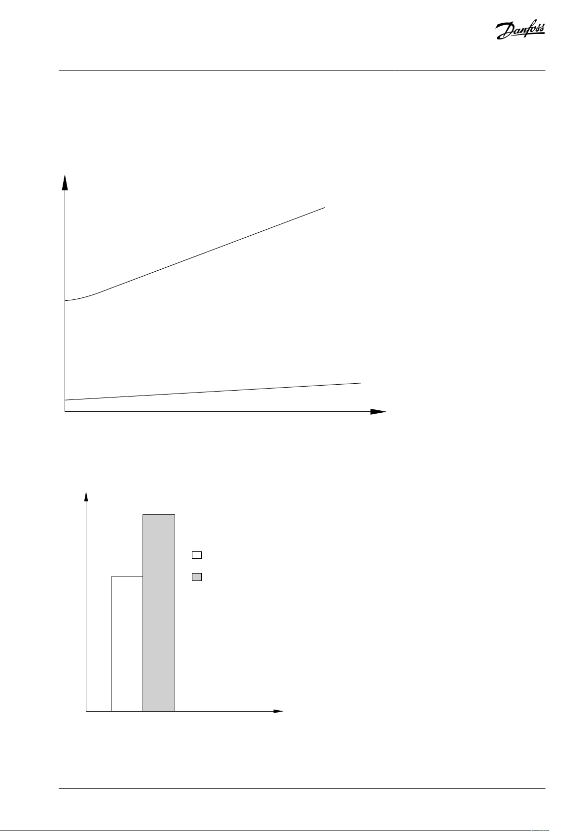
e30bb955.12
a
b
Motor cable length
Leakage current
e30bb956.12
THDv=0%
THDv=5%
Leakage current
VLT® Flow Drive FC 111
Design Guide
•
RFI filtering.
•
Motor cable length.
•
Motor cable shielding.
•
Drive power.
Product Overview
Illustration 27: Influence of the Cable Length and Power Size on Leakage Current, Power Size a > Power Size B
The leakage current also depends on the line distortion.
Illustration 28: Influence of Line Distortion on Leakage Current
If the leakage current exceeds 3.5 mA, compliance with EN/IEC 61800-5-1 (power drive system product standard) requires special
care.
Reinforce grounding with the following protective earth connection requirements:
AJ363928382091en-000101 / 130R0983 | 39Danfoss A/S © 2021.04
Page 40

e30bb958.12
Leakage current
Frequency
3rd harmonics
Mains Cable
RCD with low f
cut-off
RCD with high f
cut-off
50 Hz
150 Hz
f
sw
VLT® Flow Drive FC 111
Design Guide
•
Ground wire (terminal 95) of at least 10 mm2 (8 AWG) cross-section.
•
2 separate ground wires both complying with the dimensioning rules.
Product Overview
See EN/IEC 61800-5-1 and IEC EN 62477-1 for further information.
W A R N I N G
DISCHARGE TIME
Touching the electrical parts, even after the equipment has been disconnected from mains, could be fatal.
Make sure that other voltage inputs have been disconnected, such as load sharing (linkage of DC-link), and the motor con-
-
nection for kinetic back-up.
Before touching any electrical parts, wait at least the amount of time indicated in the safety chapter. Shorter time is allowed
-
only if indicated on the nameplate for the specific unit.
W A R N I N G
LEAKAGE CURRENT HAZARD
Leakage currents exceed 3.5 mA. Failure to ground the drive properly can result in death or serious injury.
Ensure the correct grounding of the equipment by a certified electrical installer.
-
3.6.1 Using a Residual Current Device (RCD)
Where residual current devices (RCDs), also known as earth leakage circuit breakers (ELCBs), are used, comply with the following:
•
Use RCDs of type B only, which are capable of detecting AC and DC currents.
•
Use RCDs with an inrush delay to prevent faults caused by transient ground currents.
•
Dimension RCDs according to the system configuration and environmental considerations.
The leakage current includes several frequencies originating from both the mains frequency and the switching frequency. Whether
the switching frequency is detected depends on the type of RCD used.
Illustration 29: Mains Contributions to Leakage Current
The amount of leakage current detected by the RCD depends on the cut-off frequency of the RCD.
AJ363928382091en-000101 / 130R098340 | Danfoss A/S © 2021.04
Page 41

e30bb957.12
Leakage current [mA]
100 Hz
2 kHz
100 kHz
VLT® Flow Drive FC 111
Design Guide
Product Overview
Illustration 30: Influence of Cut-off Frequency of the RCD on what is Responded to/Measured
For more details, refer to the RCD Application Note.
RESIDUAL CURRENT DEVICE PROTECTION
This product can cause a DC current in the protective conductor. Where a residual current device (RCD) is used for protection in
case of direct or indirect contact, only an RCD of Type B is allowed on the supply side of this product. Otherwise, apply another
protective measure, such as separation from the environment by double or reinforced insulation, or isolation from the supply
system by a transformer. See also application note Protection against Electrical Hazards.
-
3.7 Extreme Running Conditions
3.7.1 Introduction
Short circuit (motor phase-phase)
Current measurement in each of the 3 motor phases or in the DC-link, protects the drive against short circuits. A short circuit between 2 output phases causes an overcurrent in the inverter. The inverter is turned off individually when the short circuit current
exceeds the allowed value (alarm 16, Trip Lock).
For information about protecting the drive against a short circuit at the load sharing and brake outputs, see chapter Fuses and Circuit
Breakers.
Switching on the output
Switching on the output between the motor and the drive is allowed. The drive is not damaged in any way by switching on the
output. However, fault messages may appear.
Motor-generated overvoltage
The voltage in the DC link is increased when the motor acts as a generator. This occurs in following cases:
•
•
•
The control unit may attempt to correct the ramp if parameter 2-17 Over-voltage Control is enabled. The drive turns off to protect the
transistors and the DC-link capacitors when a certain voltage level is reached.
W A R N I N G
Protective grounding of the drive and the use of RCDs must always follow national and local regulations.
The load drives the motor (at constant output frequency from the drive), that is the load generates energy.
During deceleration (ramp-down) if the inertia moment is high, the friction is low, and the rampdown time is too short for the
energy to be dissipated as a loss in the drive, the motor, and the installation.
Incorrect slip compensation setting (parameter 1-62 Slip Compensation) may cause higher DC-link voltage.
AJ363928382091en-000101 / 130R0983 | 41Danfoss A/S © 2021.04
Page 42

1.21.0 1.4
30
10
20
100
60
40
50
1.81.6 2.0
2000
500
200
400
300
1000
600
t [s]
e75za052.13
I
M,N
(parameter 1-24)
I
M
f
OUT
= 2 x f
M,N
(parameter 1-23)
f
OUT
= 1 x f
M,N
f
OUT
= 0.2 x f
M,N
VLT® Flow Drive FC 111
Design Guide
Product Overview
Mains drop-out
During a mains dropout, the drive keeps running until the DC-link voltage drops below the minimum stop level, which is typically
15% below the drive's lowest rated supply voltage. The mains voltage before the drop-out and the motor load determines how long
it takes for the drive to coast.
3.7.2 Motor Thermal Protection (ETR)
Danfoss uses ETR to protect the motor from being overheated. It is an electronic feature that simulates a bimetal relay based on
internal measurements. The characteristic is shown in the following illustration.
Illustration 31: Motor Thermal Protection Characteristic
The X-axis shows the ratio between I
motor
and I
nominal. The Y-axis shows the time in seconds before the ETR cuts off and trips
motor
the drive. The curves show the characteristic nominal speed at twice the nominal speed and at 0.2x the nominal speed.
It is clear that at lower speed the ETR cuts off at lower heat due to less cooling of the motor. In that way, the motor is protected from
being overheated even at low speed. The ETR feature calculates the motor temperature based on actual current and speed.
3.7.3 Thermistor Inputs
The thermistor cutout value is >3 kΩ.
Integrate a thermistor (PTC sensor) in the motor for winding protection.
Motor protection can be implemented using a range of techniques:
•
PTC sensor in motor windings.
•
Mechanical thermal switch (Klixon type).
•
Electronic thermal relay (ETR).
AJ363928382091en-000101 / 130R098342 | Danfoss A/S © 2021.04
Page 43

1330
550
250
-20°C
e75ha183.10
4000
3000
R
(W)
nominel
nominel -5°C
nominel + 5°C
[°C ]
R
OFF
ON
<800 Ω >2.9 κΩ
18
19
12 20 55
27 29 42 45 50 53 54
DIGI IN
DIGI IN
DIGI IN
DIGI IN
61
68
69
N
P
C OMM. GND
+24V
0/4-20mA A OUT / DIG OUT 0/4-20mA A OUT / DIG OUT
C OM A IN
C OM DIG IN
10V/20mA IN
10V/20mA IN
10V OUT
BUS
TER.
OFF
ON
e30bb898.10
VLT® Flow Drive FC 111
Design Guide
Illustration 32: Trip due to High Motor Temperature
Product Overview
3.7.3.1 Example with Digital Input and 10 V Power Supply
The drive trips when the motor temperature is too high.
Parameter set-up:
•
Set parameter 1-90 Motor Thermal Protection to [2] Thermistor Trip.
•
Set parameter 1-93 Thermistor Source to [6] Digital Input 29.
Illustration 33: Digital Input/10 V Power Supply
3.7.3.2 Example with Analog Input and 10 V Power Supply
The drive trips when the motor temperature is too high.
Parameter set-up:
AJ363928382091en-000101 / 130R0983 | 43Danfoss A/S © 2021.04
Page 44

18
19
12 20 55
27 29 42 45 50 53 54
DIGI IN
DIGI IN
DIGI IN
DIGI IN
61
68
69
N
P
C OMM. GND
+24V
0/4-20mA A OUT / DIG OUT 0/4-20mA A OUT / DIG OUT
C OM A IN
C OM DIG IN
10V/20mA IN
10V/20mA IN
10V OUT
BUS
TER.
OFF
ON
e30bb897.10
R
<3.0 k
Ω
>2.9k Ω
OFF
ON
Input
Supply voltage [V]
Threshold cutout values [Ω]
Digital
10
<800⇒2.9 k
Analog
10
<800⇒2.9 k
VLT® Flow Drive FC 111
Design Guide
•
Set parameter 1-90 Motor Thermal Protection to [2] Thermistor Trip.
•
Set parameter 1-93 Thermistor Source to [1] Analog Input 53.
N O T I C E
Do not set Analog Input 54 as reference source.
Product Overview
Illustration 34: Analog Input/10 V Power Supply
Table 19: Supply Voltage
Make sure that the selected supply voltage follows the specification of the used thermistor element.
ETR is activated in parameter 1-90 Motor Thermal Protection.
N O T I C E
AJ363928382091en-000101 / 130R098344 | Danfoss A/S © 2021.04
Page 45

F C - P
T
H
X S A B C X X X X
1 2 3 4 5 6 7 8 9
10
11 12 13
14
15 16 17
18
19 20 30 22 21 23 27 25 24 26 28 29 31 37 36 35 34 33 32 38
39
X
1 D 1
1
X
X
X
X X X
X X X
Description
Position
Possible choice
Product group & FC series
1–6
FC 111
Power rating
7–10
0.37–315 kW (0.5–450 hp) (PK37-P315)
Number of phases
11
3 phases (T)
Mains voltage
11–12
T4: 380-480 V AC
Enclosure
13–15
E20: IP20/chassis
P20: IP20/chassis with back plate
RFI filter
16–17
H1: RFI filter class A1/B
H2: RFI filter class A2
H3: RFI filter class A1/B (reduced cable length)
H4: RFI filter class A1
Brake
18
X: No brake chopper included
Display
19
A: Alpha numeric local control panel
X: No local control panel
Coating PCB
20
X: No coated PCB
C: Coated PCB
Mains option
21
X: No mains option
Adaptation
22
X: No adaptation
Adaptation
23
X: No adaptation
Software release
24–27
SXXXX: Latest release - standard software
Software language
28
X: Standard
A options
29–30
AX: No A options
B options
31–32
BX: No B options
C0 options MCO
33–34
CX: No C options
C1 options
35
X: No C1 options
C option software
36–37
XX: No options
VLT® Flow Drive FC 111
Design Guide
Selection and Ordering
4 Selection and Ordering
4.1 Type Code
A type code defines a specific configuration of the drive. Use the following illustration to create a type code string for the desired
configuration.
Illustration 35: Type Code
Table 20: Type Code Description
AJ363928382091en-000101 / 130R0983 | 45Danfoss A/S © 2021.04
Page 46

D options
38–39
DX: No D0 options
Ordering number
Description
132B0200
LCP 31
132B9221
LCP 32
Enclosure
Front-mounted
Maximum cable length to unit
3 m (10 ft)
Communication standard
RS485
VLT® Flow Drive FC 111
Design Guide
4.2 Options and Accessories
4.2.1 Local Control Panel (LCP)
Table 21: Ordering Number of LCP
Table 22: Technical Data of LCP
Selection and Ordering
4.2.2 IP21 Enclosure Kit
IP21 is an optional enclosure element available for IP20 units. If the enclosure kit is used, an IP20 unit is upgraded to comply with
enclosure IP21.
AJ363928382091en-000101 / 130R098346 | Danfoss A/S © 2021.04
Page 47

e30bb902.12
A
B
C
VLT® Flow Drive FC 111
Design Guide
Selection and Ordering
Illustration 36: H1–H5
AJ363928382091en-000101 / 130R0983 | 47Danfoss A/S © 2021.04
Page 48

e30bb903.10
Frame
IP class
3x380-480 V [kW (hp)]
Height [mm (in)] A
Width [mm (in)] B
Depth [mm (in)] C
IP21 kit ordering
number
H1
IP20
0.37–1.5 (0.5–2.0)
293 (11.5)
81 (3.2)
173 (6.8)
132B0212
H2
IP20
2.2-4.0 (3.0–5.4)
322 (12.7)
96 (3.8)
195 (7.7)
132B0213
H3
IP20
5.5-7.5 (7.4–10)
346 (13.6)
106 (4.2)
210 (8.3)
132B0214
H4
IP20
11–15 (15–20)
374 (14.7)
141 (5.6)
245 (9.6)
132B0215
H5
IP20
18.5–22 (25–30)
418 (16.5)
161 (6.3)
260 (10.2)
132B0216
H6
IP20
30–45 (40–60)
663 (26.1)
260 (10.2)
242 (9.5)
132B0217
H7
IP20
55–75 (74–100)
807 (31.8)
329 (13.0)
335 (13.2)
132B0218
H8
IP20
90 (120)
943 (37.1)
390 (15.3)
335 (13.2)
132B0219
VLT® Flow Drive FC 111
Design Guide
Selection and Ordering
Illustration 37: Dimensions
Table 23: Enclosure Kit Specifications
4.2.3 Decoupling Plate
Use the decoupling plate for EMC-correct installation. The following illustration shows the decoupling plate on an H3 enclosure.
AJ363928382091en-000101 / 130R098348 | Danfoss A/S © 2021.04
Page 49

99
99
e30bb793.11
Frame
IP class
3x380–480 V
Decoupling plate ordering numbers
H1
IP20
0.37–1.5 (0.5–2.0)
132B0202
H2
IP20
2.2–4.0 (3.0–5.4)
132B0202
H3
IP20
5.5–7.5 (7.5–10)
132B0204
H4
IP20
11–15 (15–20)
132B0205
H5
IP20
18.5–22 (25–30)
132B0205
H6
IP20
30 (40)
132B0207
H6
IP20
37–45 (50–60)
132B0242
H7
IP20
55 (75)
132B0208
H7
IP20
75 (100)
132B0243
H8
IP20
90 (125)
132B0209
Enclo-
sure
size
Mains
volt-
age
H1 [kW
(hp)]
H2 [kW
(hp)]
H3 [kW
(hp)]
H4 [kW
(hp)]
H5 [kW
(hp)]
H6 [kW (hp)]
H7 [kW (hp)]
H8 [kW
(hp)]
VLT® Flow Drive FC 111
Design Guide
Selection and Ordering
Illustration 38: Decoupling Plate
Table 24: Decoupling Plate Specifications
4.3 Ordering Numbers
4.3.1 Options and Accessories
Table 25: Options and Accessories
AJ363928382091en-000101 / 130R0983 | 49Danfoss A/S © 2021.04
Page 50

T4
(380–
480 V
AC)
0.37–1.5
(0.5–2.0)
2.2–4.0
(3.0–5.4)
5.5–7.5
(7.5–10)
11–15
(15–20)
18.5–22
(25–30)
30 (40)
37–45
(50–60)
55 (75)
75 (100)
90 (125)
Description
LCP
(1)
132B0200
LCP
panel
mounting kit
including 3 m
(9.8 ft)
cable
132B0201
Decoupling
plate
132B0202
132B0202
132B0204
132B0205
132B0205
132B0207
132B0242
132B0208
132B0243
132B0209
IP21
option
132B0212
132B0213
132B0214
132B0215
132B0216
132B0217
132B0218
132B0219
3x380–480 V 50 Hz
Power [kW (hp)]
Drive input current continuous
[A]
Default switching
frequency [kHz]
THDi level [%]
Order number filter
IP00
Code number filter
IP20
22 (30)
41.544
130B1397
130B1239
30 (40)
5743
130B1398
130B1240
37 (50)
7043
130B1442
130B1247
45 (60)
8433
130B1442
130B1247
55 (74)
10335
130B1444
130B1249
75 (100)
14034
130B1445
130B1250
90 (120)
17634
130B1445
130B1250
3x380–480 V 50 Hz
Power [kW (hp)]
Drive input current continuous
[A]
Default switching
frequency [kHz]
THDi level [%]
Order number filter
IP00
Code number filter
IP20
22 (30)
41.546
130B1274
130B1111
30 (40)
5746
130B1275
130B1176
37 (50)
7049
130B1291
130B1201
VLT® Flow Drive FC 111
Design Guide
Selection and Ordering
1
For IP20 units, LCP is ordered separately.
4.3.2 Harmonic Filters
Table 26: AHF Filters (5% Current Distortion)
Table 27: AHF Filters (10% Current Distortion)
AJ363928382091en-000101 / 130R098350 | Danfoss A/S © 2021.04
Page 51

45 (60)
8439
130B1291
130B1201
55 (74)
10339
130B1292
130B1204
75 (100)
14038
130B1294
130B1213
90 (120)
17638
130B1294
130B1213
3x440–480 V 60 Hz
Power [kW (hp)]
Drive input current Continuous
[A]
Default switching
frequency [kHz]
THDi level [%]
Order number filter
IP00
Code number filter
IP20
22 (30)
34.643
130B1792
130B1757
30 (40)
4943
130B1793
130B1758
37 (50)
6143
130B1794
130B1759
45 (60)
7334
130B1795
130B1760
55 (74)
8934
130B1796
130B1761
75 (100)
12135
130B1797
130B1762
90 (120)
14335
130B1798
130B1763
3x440–480 V 60 Hz
Power [kW (hp)]
Drive input current continuous
[A]
Default switching
frequency [kHz]
THDi level [%]
Order number filter
IP00
Code number filter
IP20
22 (30)
34.646
130B1775
130B1487
30 (40)
4948
130B1776
130B1488
37 (50)
6147
130B1777
130B1491
45 (60)
7339
130B1778
130B1492
55 (74)
8938
130B1779
130B1493
75 (100)
12139
130B1780
130B1494
90 (120)
143310
130B1781
130B1495
Power
[kW
(hp)]
Size
380–
480 V
TypeABCDEFGHIJKL1
Torque
[Nm (inlb)]
Weight
[kg (lb)]
Ordering
Number
VLT® Flow Drive FC 111
Design Guide
Table 28: AHF Filters (5% Current Distortion)
Selection and Ordering
Table 29: AHF Filters (10% Current Distortion)
4.3.3 External RFI Filter
With external filters listed in the following table, the maximum shielded cable length of 50 m (164 ft) according to EN/IEC 61800-3
C2 (EN 55011 A1), or 20 m (65.6 ft) according to EN/IEC 61800-3 C1(EN 55011 B) can be achieved.
Table 30: RFI Filters - Details
AJ363928382091en-000101 / 130R0983 | 51Danfoss A/S © 2021.04
Page 52

0.37–
2.2
(0.5–
3.0)
FN3258-7-45
1904070
160
180204.5110.6M520310.7–0.8
(6.2–
7.1)
0.5 (1.1)
132B0244
3.0–7.5
(4.0–10)
FN3258-16-45
2504570
220
235254.5110.6M522.5310.7–0.8
(6.2–
7.1)
0.8 (1.8)
132B0245
11–15
(15–20)
FN3258-30-47
2705085
240
255305.4110.6M525401.9–2.2
(16.8–
19.5)
1.2 (2.6)
132B0246
18.5–22
(25–30)
FN3258-42-47
3105085
280
295305.4110.6M525401.9–2.2
(16.8–
19.5)
1.4 (3.1)
132B0247
H
B
K
C
A
D
J
G
E
F
l
1
L
1
e30bc247.10
VLT® Flow Drive FC 111
Design Guide
Selection and Ordering
Illustration 39: RFI Filter - Dimensions
AJ363928382091en-000101 / 130R098352 | Danfoss A/S © 2021.04
Page 53

e
f
a
e
e
f
a
d
e
A
a
b
B
C
D
e30bf984.10
Enclosure Size
H1H2H3
H4
IP class
IP20
IP20
IP20
IP20
Power [kW (hp)]
3x380–480 V
0.37–1.5
(0.5–2.0)
2.2–4.0
(3.0–5.0)
5.5–7.5
(7.5–10)
11–15
(15–20)
Height [mm (in)]
A
195 (7.7)
227 (8.9)
255 (10.0)
296 (11.7)
A
(1)
273 (10.7)
303 (11.9)
329 (13.0)
359 (14.1)
a
183 (7.2)
212 (8.3)
240 (9.4)
275 (10.8)
Width [mm (in)]
B
75 (3.0)
90 (3.5)
100 (3.9)
135 (5.3)
b
56 (2.2)
65 (2.6)
74 (2.9)
105 (4.1)
Depth [mm (in)]
C
168 (6.6)
190 (7.5)
206 (8.1)
241 (9.5)
Mounting hole [mm (in)]
d
9 (0.35)
11 (0.43)
11 (0.43)
12.6 (0.50)
e
4.5 (0.18)
5.5 (0.22)
5.5 (0.22)
7 (0.28)
f
5.3 (0.21)
7.4 (0.29)
8.1 (0.32)
8.4 (0.33)
Maximum weight kg (lb)
2.1 (4.6)
3.4 (7.5)
4.5 (9.9)
7.9 (17.4)
Enclosure Size
H5H6H7
H8
IP class
IP20
IP20
IP20
IP20
Power [kW (hp)]
3x380–480 V
18.5–22
(25–30)
30–45
(40–60)
55–75
(70–100)
90 (125)
Height [mm (in)]
A
334 (13.1)
518 (20.4)
550 (21.7)
660 (26)
A
(1)
402 (15.8)
595 (23.4)/635 (25), 45 kW
630 (24.8)/690 (27.2), 75 kW
800 (31.5)
VLT® Flow Drive FC 111
Design Guide
5 Mechanical Installation Considerations
5.1 Power Ratings, Weights, and Dimensions
Illustration 40: Dimensions, Enclosure Sizes H1–H8
Mechanical Installation
Considerations
Table 31: Power Ratings, Weights, and Dimensions, Enclosure Sizes H1–H4
1
Including decoupling plate.
Table 32: Power Ratings, Weights, and Dimensions H6–H8
AJ363928382091en-000101 / 130R0983 | 53Danfoss A/S © 2021.04
Page 54
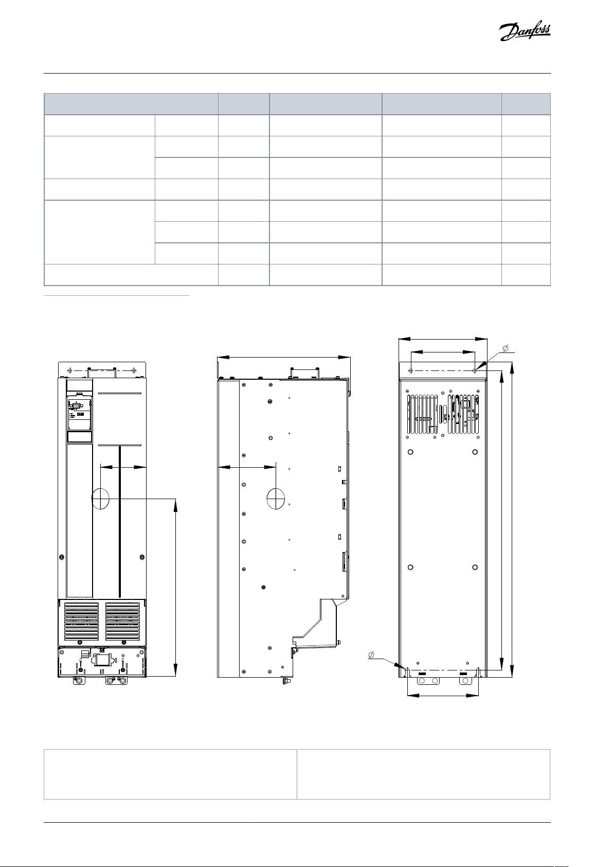
Enclosure Size
H5H6H7
H8a314 (12.4)
495 (19.5)
521 (20.5)
631 (24.8)
Width [mm (in)]
B
150 (5.9)
239 (9.4)
313 (12.3)
375 (14.8)
b
120 (4.7)
200 (7.9)
270 (10.6)
330 (13)
Depth [mm (in)]
C
255 (10)
242 (9.5)
335 (13.2)
335 (13.2)
Mounting hole [mm (in)]
d
12.6 (0.50)
–––e7 (0.28)
8.5 (0.33)
8.5 (0.33)
8.5 (0.33)
f
8.5 (0.33)
15 (0.6)
17 (0.67)
17 (0.67)
Maximum weight kg (lb)
9.5 (20.9)
24.5 (54)
36 (79)
51 (112)
e30bu775.10
C
D
b1
B
b D
A
a
E
F
G
(1) (2)
(3)
1
Front view
2
Side view
3
Back view
VLT® Flow Drive FC 111
Design Guide
1
Including decoupling plate.
Mechanical Installation
Considerations
Illustration 41: Dimensions, Enclosure Sizes H13–H14
AJ363928382091en-000101 / 130R098354 | Danfoss A/S © 2021.04
Page 55

Enclosure Size
H13
H14
IP class
IP20
IP20
Power [kW (hp)]
3x380–480 V
110–160
(150–250)
200–315
(300–450)
Height [mm (in)]
A
889 (35.0)
1096 (43.1)
A
(1)
909 (35.8)
1122 (44.2)
a
844 (33.2)
1051 (41.4)
Width [mm (in)]
B
250 (9.8)
350 (13.8)
b
180 (7.1)
280 (11.0)
b1
200 (7.9)
271 (10.7)
Depth [mm (in)]
C
375 (14.8)
375 (14.8)
Mounting hole [mm (in)]
D
11 (0.4)
11 (0.4)
Center of gravity [mm (in)]
E
128 (5.0)
176 (6.9)
F
495 (19.5)
611 (24.1)
G
148 (5.8)
148 (5.8)
Maximum weight kg (lb)
98 (216)
164 (362)
Power [kW (hp)]
Clearance above/below [mm (in)]
Size
IP class
3x380–480 V
H1
IP20
0.37–1.5 (0.5–2.0)
100 (4)
H2
IP20
2.2–4.0 (3.0–5.4)
100 (4)
H3
IP20
5.5–7.5 (7.5–10)
100 (4)
H4
IP20
11–15 (15–20)
100 (4)
H5
IP20
18.5–22 (25–30)
100 (4)
H6
IP20
30–45 (40–60)
200 (7.9)
H7
IP20
55–75 (70–100)
200 (7.9)
H8
IP20
90 (125)
225 (8.9)
VLT® Flow Drive FC 111
Design Guide
Table 33: Power Ratings, Weights, and Dimensions H13–H14
Mechanical Installation
Considerations
1
Including decoupling plate.
The dimensions are only for the physical units.
5.2 Mechanical Installation H1-H8
5.2.1 Side-by-side Installation
The drive can be mounted side by side but requires the clearance above and below for cooling.
Table 34: Clearance Required for Cooling
AJ363928382091en-000101 / 130R0983 | 55Danfoss A/S © 2021.04
Page 56

VLT® Flow Drive FC 111
Design Guide
N O T I C E
With IP21 option kit mounted, a distance of 50 mm (2 in) between the units is required.
5.3 Mechanical Installation H13-H14
5.3.1 Tools Needed
Receiving/unloading
•
I-beam and hooks rated to lift the weight of the drive. Refer to 5.1 Power Ratings, Weights, and Dimensions.
•
Crane or other lifting aid to place the unit into position.
Installation
•
Drill with a 12 mm (1/2 in) drill bit.
•
Tape measurer.
•
Phillips and flat bladed screwdrivers.
•
Wrench with 7–17 mm metric sockets.
•
Wrench extensions.
•
T25 and T50 Torx drives.
•
Sheet metal punch and/or pliers for cable entry plate.
Mechanical Installation
Considerations
5.3.2 Installation and Cooling Requirements
N O T I C E
OVERHEATING
Improper mounting can result in overheating and reduced performance.
Install the drive according to the installation and cooling requirements.
-
Installation requirements
•
Ensure drive stability by mounting the drive vertically to a solid flat surface.
•
Ensure that the strength of the mounting location supports the drive weight. Ensure that the mounting location allows access
to open the enclosure door. Refer to 5.1 Power Ratings, Weights, and Dimensions.
•
Ensure that there is enough space around the drive for cooling airflow.
•
Place the drive as near to the motor as possible. Keep the motor cables as short as possible. See 9.2.4 Cable Length and Cross-
section.
•
Ensure that the location allows for cable entry at the bottom of the drive.
Cooling and airflow requirements
•
Ensure that top and bottom clearance for air cooling is provided. Clearance requirement: 225 mm (9 in).
•
Consider derating for temperatures starting between 45 °C (113 °F) and 50 °C (122 °F) and elevation 1000 m (3300 ft) above sea
level. See chapter Derating for detailed information.
The drive uses back-channel cooling to circulate the heat sink cooling air. The cooling duct carries approximately 90% of the heat
out of the back channel of the drive. Redirect the back-channel air from the panel or room by using:
•
Duct cooling. Back-channel cooling kits are available to direct the air away from the panel when an IP20/chassis drive is installed
in a Rittal enclosure. Use of a kit reduces the heat in the panel and smaller door fans can be specified on the enclosure.
•
Cooling out the back (top and base covers). The back-channel cooling air can be ventilated out of the room so that the heat
from the back channel is not dissipated into the control room.
N O T I C E
One or more door fans are required on the enclosure to remove heat not contained in the back channel of the drive. The fans also
remove any additional losses generated by other components inside the drive.
AJ363928382091en-000101 / 130R098356 | Danfoss A/S © 2021.04
Page 57

Enclosure size
Door fan/top fan
Heat sink fan
H13
102 m3/hr (60 CFM)
420 m3/hr (250 CFM)
H14
204 m3/hr (120 CFM)
840 m3/hr (500 CFM)
e30bg512.11
65° min
VLT® Flow Drive FC 111
Mechanical Installation
Design Guide
Ensure that the fans supply adequate airflow over the heat sink. To select the appropriate number of fans, calculate the total required airflow. The flow rate is shown in the following table.
Table 35: Airflow
Considerations
5.3.3 Lifting the Drive
W A R N I N G
HEAVY LOAD
Unbalanced loads can fall or tip over. Failure to take proper lifting precautions increases risk of death, serious injury, or equip-
ment damage.
Move the unit using a hoist, crane, forklift, or other lifting device with the appropriate weight rating. See 5.1 Power Ratings,
-
Weights, and Dimensions for the weight of the drive.
Failure to locate the center of gravity and correctly position the load can cause unexpected shifting during lifting and trans-
-
port. For measurements and center of gravity, see 5.1 Power Ratings, Weights, and Dimensions.
The angle from the top of the drive module to the lifting cables affects the maximum load force on the cable. This angle
-
must be 65° or greater. Refer to the following illustration. Attach and dimension the lifting cables properly.
Never walk under suspended loads.
-
To guard against injury, wear personal protective equipment such as gloves, safety glasses, and safety shoes.
-
Always lift the drive using the dedicated eye bolts at the top of the drive. See the following illustration.
Illustration 42: Lifting the Drive
AJ363928382091en-000101 / 130R0983 | 57Danfoss A/S © 2021.04
Page 58

1
2
e30bg288.10
1
Top mounting holes
2
Lower fastener slots
VLT® Flow Drive FC 111
Mechanical Installation
Design Guide
Considerations
5.3.4 Wall Mounting the Drive
H13 and H14 are chassis drives intended to be mounted on a wall or on a mounting plate within an enclosure. To wall mount the
drive, use the following steps.
Procedure
1.
Fasten 2 M10 bolts in the wall to align with the fastener slots at the bottom of drive.
2.
Slide the lower fastener slots in the drive over the M10 bolts.
3.
Tip the drive against the wall, and secure the top with 2 M10 bolts in the mounting holes.
Example
Illustration 43: Drive-to-wall Mounting Holes
AJ363928382091en-000101 / 130R098358 | Danfoss A/S © 2021.04
Page 59

1
e30bf662.10
2
1
Plastic tabs
2
Tabs removed for cable access
e30bg823.10
225 mm (8.9 in)
225 mm (8.9 in)
VLT® Flow Drive FC 111
Mechanical Installation
Design Guide
Considerations
5.3.5 Creating Cable Openings
After installing the drive, create cable openings in the gland plate to accommodate the mains and motor cables. The gland plate is
required to maintain the drive protection rating.
Procedure
1.
Punch out plastic tabs to accommodate the cables.
Illustration 44: Cable Openings in Plastic Gland Plate
5.3.6 Back-channel Cooling
A unique back-channel duct passes cooling air over the heat sinks with minimal air passing through the electronics area. There is an
IP54/Type 12 seal between the back-channel cooling duct and the electronics area of the VLT® drive. This back-channel cooling
allows 90% of the heat losses to be exhausted directly outside the enclosure. This design improves reliability and prolongs component life by dramatically reducing interior temperatures and contamination of the electronic components. Different back-channel
cooling kits are available to redirect the airflow based on individual needs.
5.3.6.1 Airflow for H13 & H14 Enclosures
Illustration 45: Standard Airflow Configuration for Enclosures H13 and H14
AJ363928382091en-000101 / 130R0983 | 59Danfoss A/S © 2021.04
Page 60

VLT® Flow Drive FC 111
Mechanical Installation
Design Guide
Considerations
5.4 Derating
5.4.1 Manual Derating and Automatic Derating
Derating is a method used to reduce output current to avoid tripping the drive when high temperatures are reached within the
enclosure. If certain extreme operating conditions are expected, a higher-powered drive can be selected to eliminate the need for
derating. This is called manual derating. Otherwise, the drive automatically derates the output current to eliminate the excessive
heat generated by extreme conditions.
Manual derating
When the following conditions are present, Danfoss recommends selecting a drive 1 power size higher (for example P132 instead of
P110):
•
Low-speed – continuous operation at low RPM in constant torque applications.
•
Low air pressure – operating at altitudes above 1000 m (3281 ft).
•
High ambient temperature – operating at ambient temperatures of 10 °C (50 °F).
•
High switching frequency.
•
Long motor cables.
•
Cables with a large cross-section.
Automatic derating
If the following operating conditions are found, the drive automatically changes switching frequency or switching pattern (PWM to
SFAVM) to reduce excessive heat within the enclosure:
•
High temperature on the control card or heat sink.
•
High motor load or low motor speed.
•
High DC-link voltage.
5.4.2 Derating for Low-speed Operation
When a motor is connected to a drive, it is necessary to ensure that the cooling of the motor is adequate. The level of cooling required depends on the following:
•
Load on the motor.
•
Operating speed.
•
Length of operating time.
Constant torque applications (CT mode)
In a constant torque application, a motor may overheat at low speeds because the fan within the motor is providing less cooling air.
Therefore, if the motor is to be run continuously at an RPM value lower than half of the rated value, the motor must be supplied
with extra air cooling. If extra air cooling is not available, use a motor designed for low RPM/constant torque applications, or select a
larger motor to reduce the load level.
Variable (quadratic) torque applications (VT)
In variable torque applications where the torque is proportional to the square of the speed and the power is proportional to the
cube of the speed, there is no need for extra cooling or derating of the motor. Common variable torque applications are centrifugal
pumps and fans.
5.4.3 Derating for Low Air Pressure and High Altitudes
The cooling capability of air is decreased at low air pressure. For altitudes above 2000 m (6562 ft), contact Danfoss regarding PELV.
Below 1000 m (3281 ft) altitude, derating is not necessary. For altitudes above 1000 m (3281 ft), decrease the ambient temperature
or the maximum output current. Decrease the output by 1% per 100 m (328 ft) altitude above 1000 m (3281 ft) or reduce the maximum ambient cooling air temperature by 1 °C (1.8 °F) per 200 m (656 ft).
5.4.4 Derating for Ambient Temperature and Switching Frequency
Ensure that the ambient temperature measured over 24 hours is at least 5 °C (9 °F) lower than the maximum ambient temperature
that is specified for the drive. If the drive is operated at a high ambient temperature, decrease the constant output current.
N O T I C E
FACTORY DERATING
Danfoss drives have already derated for operational temperature (55 °C (131 °F) T
and 50 °C (122 °F) T
AMB,MAX
).
AMB,AVG
AJ363928382091en-000101 / 130R098360 | Danfoss A/S © 2021.04
Page 61

e30bc218.11
fsw[kHz]
20 10
0
10%
20%
30%
40%
50%
60%
70%
80%
90%
100%
110%
Iout[%]
165
40 C
104 F
。
。
45 C
113 F
。
。
50 C
122 F
。
。
0.37–1.5 kW (0.5–2.0 hp), 400 V, Enclosure Size H1, IP20
e30bc220.11
fsw[kHz]
20 10
0
10%
20%
30%
40%
50%
60%
70%
80%
90%
100%
110%
I
out[%]
165
40 C
104 F
。
。
45 C
113 F
。
。
50 C
122 F
。
。
2.2–4.0 kW (3.0–5.4 hp), 400 V, Enclosure Size H2, IP20
e30bc222.11
fsw[kHz]
20 10
0
10%
20%
30%
40%
50%
60%
70%
80%
90%
100%
110 %
I
out[%]
165
40 C
104 F
。
。
45 C
113 F
。
。
50 C
122 F
。
。
5.5–7.5 kW (7.4–10 hp), 400 V, Enclosure Size H3, IP20
e30bc224.10
fsw[kHz]
20 10
0
10%
20%
30%
40%
50%
60%
70%
80%
90%
100%
110%
I
out[%]
16
5
40 C
104 F
。
。
45 C
113 F
。
。
50 C
122 F
。
。
11–15 kW (15–20 hp), 400 V, Enclosure Size H4, IP20
e30bc226.10
fsw[kHz]
20 10
0
10%
20%
30%
40%
50%
60%
70%
80%
90%
100%
110%
I
out[%]
16
5
40 C 104 F
。 。
50 C 122 F
。 。
45 C 113 F
。 。
18.5–22 kW (25–30 hp), 400 V, Enclosure Size H5, IP20
e30bc228.10
Iout [%]
fsw [
kHz
]
20%
2 4 6 8 10 12
40%
60%
80%
100%
110%
40 C 104 F
。 。
50 C 122 F
。 。
45 C 113 F
。 。
30–37 kW (40–50 hp), 400 V, Enclosure Size H6, IP20
VLT® Flow Drive FC 111
Mechanical Installation
Design Guide
Use the following graphs to determine if the output current must be derated based on switching frequency and ambient temperature. When referring to the graphs, I
indicates the percentage of rated output current, and fsw indicates the switching frequency.
out
Considerations
AJ363928382091en-000101 / 130R0983 | 61Danfoss A/S © 2021.04
Page 62

e30bc229.10
40 C 104 F
。 。
50 C 122 F
。 。
45 C 113 F
。 。
Iout [%]
fsw [kHz]
20%
2 4 6 8 10 12
40%
60%
80%
100%
110%
45 kW (60 hp), 400 V, Enclosure Size H6, IP20
e30bc232.10
Iout [%]
fsw [kHz]
20%
2 4 6 8 10 12
40%
60%
80%
100%
110%
40 C 104 F
。 。
50 C 122 F
。 。
45 C 113 F
。 。
55–75 kW (74–100 hp), 400 V, Enclosure Size H7, IP20
e30bc235.10
Iout [%]
fsw [ kHz]
20 %
2 4 6 8 10 12
40 %
60 %
80 %
100 %
110 %
40 C 104 F
。 。
50 C 122 F
。 。
45 C 113 F
。 。
90 kW (120 hp), 400 V, Enclosure Size H8, IP20
e30bx474.11
70
80
90
1
60
100
110
2 3 4 5 6 7 8 90
50
Iout [%]
fsw
[kHz]
45 ˚C (113 ˚F)
50 ˚C (122 ˚F)
55 ˚C (131 ˚F)
110–315 kW (150–450 hp), 400 V, Enclosure Size H13–H14,
IP20, Switching Pattern 60 AVM
e30bx476.11
Iout [%]
fsw
[kHz]
70
80
90
60
100
110
2 4
60
50
1
3
5
40 ˚C (104 ˚F)
45 ˚C (113 ˚F)
50 ˚C (122 ˚F)
55 ˚C (131 ˚F)
110–315 kW (150–450 hp), 400 V, Enclosure Size H13–H14,
IP20, Switching Pattern SFAVM
VLT® Flow Drive FC 111
Design Guide
Mechanical Installation
Considerations
AJ363928382091en-000101 / 130R098362 | Danfoss A/S © 2021.04
Page 63

VLT® Flow Drive FC 111
Electrical Installation
Design Guide
Considerations
6 Electrical Installation Considerations
6.1 Safety Instructions
See chapter Safety for general safety instructions.
W A R N I N G
INDUCED VOLTAGE
Induced voltage from output motor cables from different drives that are run together can charge equipment capacitors even
with the equipment turned off and locked out. Failure to run output motor cables separately or use shielded cables could result
in death or serious injury.
Run output motor cables separately or use shielded cables.
-
Simultaneously lock out all the drives.
-
W A R N I N G
SHOCK HAZARD
The drive can cause a DC current in the ground conductor and thus result in death or serious injury. Failure to follow the recom-
mendation means that the residual current-operated protective device (RCD) cannot provide the intended protection.
When a residual current-operated protective device (RCD) is used for protection against electrical shock, only an RCD of Type
-
B is allowed on the supply side.
Overcurrent protection
•
Additional protective equipment such as short-circuit protection or motor thermal protection between drive and motor is required for applications with multiple motors.
•
Input fusing is required to provide short circuit and overcurrent protection. If fuses are not factory-supplied, the installer must
provide them. See maximum fuse ratings in chapter Fuses and Circuit Breakers.
Wire type and ratings
•
All wiring must comply with local and national regulations regarding cross-section and ambient temperature requirements.
•
Power connection wire recommendation: Minimum 75 °C (167 °F) rated copper wire.
See 9.2.4 Cable Length and Cross-section for recommended wire sizes and types.
AJ363928382091en-000101 / 130R0983 | 63Danfoss A/S © 2021.04
Page 64

L1
L2
L3
3-phase
power
input
PE
PE
+10 V DC
0-10 V DC-
0-10 V DC-
50 (+10 V OUT)
54 (A IN)
53 (A IN)
55 (COM A IN/OUT)
0/4-20 mA
0/4-20 mA
42 0/4-20 mA A OUT / D OUT
45 0/4-20 mA A OUT / D OUT
18 (D IN)
19 (D IN)
27 (D IN/OUT)
29 (D IN/OUT)
12 (+24 V OUT)
24 V (NPN)
20 (COM D IN)
O V (PNP)
24 V (NPN)
O V (PNP)
24 V (NPN)
O V (PNP)
24 V (NPN)
O V (PNP)
Bus ter.
Bus ter.
RS485
Interface
RS485
(N RS485) 69
(P RS485) 68
(Com RS485 ) 61
(PNP)-Source
(NPN)-Sink
ON=Terminated
OFF=Unterminated
ON
1 2
240 V AC 3 A
Not present on all power sizes
Do not connect shield to 61
01
02
03
relay 1
relay 2
UDC+
UDC-
Motor
U
V
W
e30bd467.12
06
05
04
240 V AC 3 A
VLT® Flow Drive FC 111
Design Guide
6.2 Electrical Wiring
Electrical Installation
Considerations
Illustration 46: Basic Wiring Schematic Drawing
N O T I C E
There is no access to UDC- and UDC+ on the following units:
IP20, 380–480 V, 30–315 kW (40–450 hp)
-
6.3 EMC-compliant Electrical Installation
To ensure EMC-correct electrical installation, observe the following:
•
Use only shielded/armored motor cables and shielded/armored control cables.
•
Ground the shield at both ends.
•
Avoid installation with twisted shield ends (pigtails), because it reduces the shielding effect at high frequencies. Use the cable
clamps provided.
•
Ensure the same potential between the drive and the ground potential of PLC.
•
Use star washers and galvanically conductive installation plates.
AJ363928382091en-000101 / 130R098364 | Danfoss A/S © 2021.04
Page 65

B
a
c
k
OK
Com.
On
Warn.
Alarm
Hand
On
Reset
Auto
On
Menu
Status Quick
Menu
Main
Menu
L1
L2
L3
PE
Minimum 16 mm
2
equalizing cable
Control cables
All cable entries in
one side of the panel
Grounding rail
Cable insulation stripped
Output contactor
Motor cable
Motor, 3 phases and
PLC
Panel
Mains-supply
Minimum 200 mm (7.87 in)
between control
cable, mains cable,
and between mains
motor cable
PLC
protective earth
Reinforced protective earth
e30bb761.13
(6 AWG)
VLT® Flow Drive FC 111
Design Guide
Electrical Installation
Considerations
Illustration 47: EMC-compliant Installation
AJ363928382091en-000101 / 130R0983 | 65Danfoss A/S © 2021.04
Page 66

e30bb634.10
1
2
2
3
4
M
ot
or
U
V
W
-DC
+DC
M
AINS
1
Mains
2
Ground
3
Motor
4
Relays
VLT® Flow Drive FC 111
Design Guide
6.4 Relays and Terminals
6.4.1 Relays and Terminals on Enclosure Sizes H1–H5
Electrical Installation
Considerations
Illustration 48: Enclosure Sizes H1–H5 IP20, 380–480 V, 0.37–22 kW (0.5–30 hp)
AJ363928382091en-000101 / 130R098366 | Danfoss A/S © 2021.04
Page 67

1
95
99
L1 91 / L2 92 / L3 93
U 96 /
V 97 /
W 98
03 02 01
06 05 04
2
3
4
e30bb762.11
1
Mains
2
Motor
3
Ground
4
Relays
1
2
3
4
e30bb763.10
VLT® Flow Drive FC 111
Design Guide
6.4.2 Relays and Terminals on Enclosure Size H6
Electrical Installation
Considerations
Illustration 49: Enclosure Size H6 IP20, 380–480 V, 30–45 kW (40–60 hp)
6.4.3 Relays and Terminals on Enclosure Size H7
Illustration 50: Enclosure Size H7 IP20, 380–480 V, 55–75 kW (70–100 hp)
AJ363928382091en-000101 / 130R0983 | 67Danfoss A/S © 2021.04
Page 68

1
Mains
2
Relays
3
Ground
4
Motor
1
2
3
4
98
97
96
99
95
93
92
91
L1
L1
L1
U
V
w
e30bb764.10
1
Mains
2
Relays
3
Ground
4
Motor
VLT® Flow Drive FC 111
Design Guide
6.4.4 Relays and Terminals on Enclosure Size H8
Electrical Installation
Considerations
Illustration 51: Enclosure Size H8 IP20, 380–480 V, 90 kW (125 hp)
AJ363928382091en-000101 / 130R098368 | Danfoss A/S © 2021.04
Page 69

e30bu777 .10
1
2
3
1
Mains
2
Motor
3
Ground
VLT® Flow Drive FC 111
Design Guide
6.4.5 Relays and Terminals on Enclosure Size H13–H14
Electrical Installation
Considerations
Illustration 52: Enclosure Size H13–H14 IP20, 380–480 V, 110–315 kW (150–450 hp)
See 6.5 View of Control Shelf for the relay terminals of H13–H14 drives.
6.5 View of Control Shelf
The control shelf of H13-H14 drives holds the keypad, known as the local control panel or LCP. The control shelf also includes the
control terminals, relays, and various connectors.
AJ363928382091en-000101 / 130R0983 | 69Danfoss A/S © 2021.04
Page 70

e30bu776.10
1
2
3
4
5
6
7
1
LCP connector
2
RS485 termination switch
3
RS485 fieldbus connector
4
Analog I/O connector
5
Digital I/O and 24 V supply
6
Relay 1 on power card
7
Relay 2 on power card
Power [kW (hp)]
Torque [Nm (in-lb)]
Enclosure size
IP class
3x380–480 V
Mains
Motor
DC connection
Control terminals
Ground
Relay
H1
IP20
0.37–1.5 (0.5–2.0)
0.8 (7)
0.8 (7)
0.8 (7)
0.5 (4)
0.8 (7)
0.5 (4)
H2
IP20
2.2–4.0 (3.0–5.4)
0.8 (7)
0.8 (7)
0.8 (7)
0.5 (4)
0.8 (7)
0.5 (4)
H3
IP20
5.5–7.5 (7.5–10)
0.8 (7)
0.8 (7)
0.8 (7)
0.5 (4)
0.8 (7)
0.5 (4)
H4
IP20
11–15 (15–20)
1.2 (11)
1.2 (11)
1.2 (11)
0.5 (4)
0.8 (7)
0.5 (4)
H5
IP20
18.5–22 (25–30)
1.2 (11)
1.2 (11)
1.2 (11)
0.5 (4)
0.8 (7)
0.5 (4)
H6
IP20
30–45 (40–60)
4.5 (40)
4.5 (40)
–
0.5 (4)
3 (27)
0.5 (4)
VLT® Flow Drive FC 111
Design Guide
Electrical Installation
Considerations
Illustration 53: View of Control Shelf in H13–H14
6.6 Fastener Tightening Torques
Apply the correct torque when tightening fasteners in the locations that are listed in the following tables. Too low or too high torque when fastening an electrical connection results in a bad electrical connection. To ensure correct torque, use a torque wrench.
Table 36: Tightening Torques for Enclosure Sizes H1–H8, 3x380–480 V
AJ363928382091en-000101 / 130R098370 | Danfoss A/S © 2021.04
Page 71

Power [kW (hp)]
Torque [Nm (in-lb)]
H7
IP20
55 (70)
10 (89)
10 (89)
–
0.5 (4)
3 (27)
0.5 (4)
H7
IP20
75 (100)
14 (124)
14 (124)
–
0.5 (4)
3 (27)
0.5 (4)
H8
IP20
90 (125)
24 (212)
(1)
24 (212)
(1)
–
0.5 (4)
3 (27)
0.5 (4)
Location
Bolt size
Torque [Nm (in-lb)]
Mains terminals
M10/M12
19 (168)/37 (335)
Motor terminals
M10/M12
19 (168)/37 (335)
Ground terminals
M8/M10
9.6 (84)/19.1 (169)
Relay terminals
–
0.5 (4)
Door/panel cover
M5
2.3 (20)
Gland plate
M5
2.3 (20)
e30bb612.10
1
1
EMC screw
VLT® Flow Drive FC 111
Design Guide
1
Cable dimensions >95 mm2.
Table 37: Tightening Torques for Enclosure Sizes H13–H14, 3x380–480 V
Electrical Installation
Considerations
6.7 IT Mains
C A U T I O N
IT MAINS
Installation on isolated mains source, that is, IT mains.
Ensure that the supply voltage does not exceed 440 V (3x380–480 V units) when connected to mains.
-
For 380–480 V, IP20, 0.37–22 kW (0.5–30 hp) units, open the RFI switch by removing the screw on the side of the drive when at IT
grid.
Illustration 54: IP20, 0.37–22 kW (0.5–30 hp), 380–480 V
If reinserted, use only M3x12 screw.
For 380–480 V, 30–90 kW (40–125 hp) units, set parameter 14-50 RFI Filter to [0] Off when operating in IT mains.
For 380–480 V, 110–315 kW (150–450 hp) units, if the drive is supplied from an isolated mains source (IT mains, floating delta, or
grounded delta) or TT/TN-S mains with grounded leg, the RFI switch is recommended to be turned off via parameter 14-50 RFI Filter
N O T I C E
AJ363928382091en-000101 / 130R0983 | 71Danfoss A/S © 2021.04
Page 72

VLT® Flow Drive FC 111
Electrical Installation
Design Guide
on the drive and parameter 14-50 RFI Filter on the filter. For more detail, see IEC 364-3. In the [Off] position, the filter capacitors between the chassis and the DC link are cut off to avoid damage to the DC link and to reduce the ground capacity currents, according
to IEC 61800-3.
If optimum EMC performance is needed, or parallel motors are connected, or the motor cable length is above 25 m (82 ft), Danfoss
recommends setting parameter 14-50 RFI Filter to [On]. It is important to use isolation monitors that are rated for use together with
power electronics (IEC 61557-8).
Considerations
6.8 Mains and Motor Connection
6.8.1 Introduction
The drive is designed to operate all standard 3-phase asynchronous motors.
Use a shielded/armored motor cable to comply with EMC emission specifications and connect this cable to both the decoupling
•
plate and the motor.
Keep the motor cable as short as possible to reduce the noise level and leakage currents.
•
•
For further details on mounting the decoupling plate, see the Decoupling Plate Mounting Instructions.
Also see EMC-Correct Installation in the
•
6.3 EMC-compliant Electrical Installation.
6.8.2 Connecting to the Ground
W A R N I N G
LEAKAGE CURRENT HAZARD
Leakage currents exceed 3.5 mA. Failure to ground the drive properly can result in death or serious injury.
Ensure that the minimum size of the ground conductor complies with the local safety regulations for high touch current
-
equipment.
For electrical safety:
•
Ground the drive in accordance with applicable standards and directives.
•
Use a dedicated ground wire for input power, motor power, and control wiring.
•
Do not ground 1 drive to another in a daisy chain fashion.
•
Keep the ground wire connections as short as possible.
•
Follow motor manufacturer wiring requirements.
•
Minimum cable cross-section: 10 mm2 (8 AWG) Cu or 16 mm2 (6 AWG) Al (or 2 rated ground wires terminated separately).
•
Tighten the terminals in accordance with the information provided in 6.6 Fastener Tightening Torques.
For EMC-compliant installation
•
Establish electrical contact between the cable shield and the drive enclosure by using metal cable glands or by using the clamps
provided on the equipment.
•
Reduce burst transient by using high-strand wire.
•
Do not use twisted shield ends (pigtails).
N O T I C E
POTENTIAL EQUALIZATION
There is a risk of burst transient when the ground potential between the drive and the control system is different.
Install equalizing cables between the system components. Recommended cable cross-section: 16 mm2 (6 AWG).
-
AJ363928382091en-000101 / 130R098372 | Danfoss A/S © 2021.04
Page 73

VLT® Flow Drive FC 111
Electrical Installation
Design Guide
Considerations
6.8.3 Connecting the Motor
W A R N I N G
INDUCED VOLTAGE
Induced voltage from output motor cables that run together can charge equipment capacitors, even with the equipment turned
off and locked out/tagged out. Failure to run output motor cables separately or to use shielded cables could result in death or
serious injury.
Run output motor cables separately or use shielded cables.
-
Simultaneously lock out/tag out all the drives.
-
•
Comply with local and national electrical codes for cable sizes. For maximum wire sizes, see 9.2.4 Cable Length and Cross-sec-
tion.
•
Follow motor manufacturer wiring requirements.
•
Motor wiring knockouts or access panels are provided at the base of IP21 (NEMA1/12) and higher units.
•
Do not wire a starting or pole-changing device (for example, Dahlander motor or slip ring asynchronous motor) between the
drive and the motor.
Procedure
1.
Strip a section of the outer cable insulation.
2.
Position the stripped wire under the cable clamp, establishing mechanical fixation and electrical contact between the cable
shield and ground.
3.
Connect the ground wire to the nearest grounding terminal in accordance with the grounding instructions provided in
6.8.2 Connecting to the Ground.
4.
Connect the 3-phase motor wiring to terminals U, V, and W.
5.
Tighten the terminals in accordance with the information provided in 6.6 Fastener Tightening Torques.
6.8.4 Connecting the AC Mains
•
Size the wiring according to the input current of the drive. For maximum wire sizes, see 9.1.1 3x380–480 V AC.
•
Comply with local and national electrical codes for cable sizes.
Procedure
1.
Strip a section of the outer cable insulation.
2.
Position the stripped wire under the cable clamp, establishing mechanical fixation and electrical contact between the cable
shield and ground.
3.
Connect the ground wire to the nearest grounding terminal in accordance with the grounding instructions provided in
6.8.2 Connecting to the Ground.
4.
For H1-H8 drives, connect the 3-phase AC input power wiring to terminals L1, L2, and L3.
5.
For H13-H14 drives, connect the 3-phase AC input power wiring to terminals R, S, and T.
6.
When supplied from an isolated mains source (IT mains or floating delta) or TT/TN-S mains with a grounded leg (grounded
delta), ensure that parameter 14-50 RFI Filter is set to [0] Off to avoid damage to the DC link and to reduce ground capacity
currents.
7.
Tighten the terminals in accordance with the information provided in 6.6 Fastener Tightening Torques.
6.9 Fuses and Circuit Breakers
6.9.1 Branch Circuit Protection
To prevent fire hazards, protect the branch circuits in an installation, switch gear, machines, and so on, against short circuits and
overcurrent. Follow national and local regulations.
6.9.2 Short-circuit Protection
Danfoss recommends using the fuses and circuit breakers listed in this chapter to protect service personnel or other equipment in
case of an internal failure in the unit or a short circuit on the DC link. The drive provides full short-circuit protection in case of a short
circuit on the motor.
AJ363928382091en-000101 / 130R0983 | 73Danfoss A/S © 2021.04
Page 74

3x380–480 V IP20 kW (hp)
Circuit breaker
Maximum fuse
0.37 (0.5)
–
gG-10
0.75 (1.0)
–
gG-10
1.5 (2.0)
–
gG-10
2.2 (3.0)
–
gG-16
3.0 (4.0)
–
gG-16
4.0 (5.4)
–
gG-16
5.5 (7.5)
–
gG-25
7.5 (10)
–
gG-25
11 (15)
–
gG-50
15 (20)
–
gG-50
18.5 (25)
–
gG-65
22 (30)
–
gG-65
30 (40)
Moeller NZMB1- A125
gG-80
37 (50)
Moeller NZMB1- A125
gG-100
45 (60)
Moeller NZMB1- A125
gG-125
55 (70)
Moeller NZMB1- A200
gG-150
75 (100)
Moeller NZMB1- A200
gG-200
90 (125)
Moeller NZMB2- A250
gG-250
110 (150)
–
aR-315
132 (175)
–
aR-350
160 (250)
–
aR-400
200 (300)
–
aR-500
250 (350)
–
aR-630
VLT® Flow Drive FC 111
Electrical Installation
Design Guide
Considerations
6.9.3 Overcurrent Protection
Provide overload protection to avoid overheating of the cables in the installation. Overcurrent protection must always be carried
out according to local and national regulations. Design circuit breakers and fuses for protection in a circuit capable of supplying a
maximum of 100000 A
(symmetrical), 480 V maximum.
rms
6.9.4 CE Compliance
To ensure compliance with IEC 61800-5-1, use the circuit breakers or fuses listed in this chapter. Circuit breakers must be designed
for protection in a circuit capable of supplying a maximum of 10000 A
(symmetrical), 480 V maximum.
rms
6.9.5 Recommendation of Fuses and Circuit Breakers
N O T I C E
In the event of malfunction, failure to follow the protection recommendation may result in damage to the drive.
Table 38: Fuses and Circuit Breakers
AJ363928382091en-000101 / 130R098374 | Danfoss A/S © 2021.04
Page 75

315 (450)
–
aR-800
Model
Fuse Options
Bussman
Littelfuse
Littelfuse
Bussman
Siba
Ferraz-Shawmut
Ferraz-Shawmut(Europe)
P110
170M2619
LA50QS300-4
L50S-300
FWH-300A
20 189 20.315
A50QS300-4
6,9URD31D08A0315
P132
170M2620
LA50QS350-4
L50S-350
FWH-350A
20 189 20.350
A50QS350-4
6,9URD31D08A0350
P160
170M2621
LA50QS400-4
L50S-400
FWH-400A
20 189 20.400
A50QS400-4
6,9URD31D08A0400
P200
170M4015
LA50QS500-4
L50S-500
FWH-500A
20 189 20.550
A50QS500-4
6,9URD31D08A0550
P250
170M4016
LA50QS600-4
L50S-600
FWH-600A
20 189 20.630
A50QS600-4
6,9URD31D08A0630
P315
170M4017
LA50QS800-4
L50S-800
FWH-800A
20 189 20.800
A50QS800-4
6,9URD32D08A0800
e30bd331.11
VLT® Flow Drive FC 111
Electrical Installation
Design Guide
Table 39: H13–H14 Power/semiconductor Fuse Options, 380–480 V
Considerations
6.10 Control Terminals
Remove the terminal cover (H1-H8) or the cradle cover (H13-H14) to access the control terminals.
H1-H8
Use a flat-edged screwdriver to push down the lock lever of the terminal cover under the LCP, then remove the terminal cover as
shown in Illustration 55.
Illustration 55: Removing the Terminal Cover
H13-H14
Press the tips of the cradle cover inwards as shown in Illustration 56, and then lift the cradle cover up.
AJ363928382091en-000101 / 130R0983 | 75Danfoss A/S © 2021.04
Page 76

e30bu793.10
e30bf892.10
12 20 55
181927 29 42 54
45 50 53
DIGI IN
61 68 69
N
P
COMM. GND
+24 V
GND
GND
10 V OUT
10 V/20 mA IN
0/4-20 mA A OUT/DIG OUT
BUS TER.
OFF ON
DIGI IN
DIGI IN
DIGI IN
0/4-20 mA A OUT/DIG OUT
10 V/20 mA IN
VLT® Flow Drive FC 111
Electrical Installation
Design Guide
Illustration 56: Removing the Cradle Cover
All the drive control terminals are shown in Illustration 57. Applying start (terminal 18), connection between terminals 12-27, and an
analog reference (terminal 53 or 54, and 55) make the drive run.
The digital input mode of terminal 18, 19, and 27 is set in parameter 5-00 Digital Input Mode (PNP is default value). Digital input 29
mode is set in parameter 5-03 Digital Input 29 Mode (PNP is default value).
Considerations
Illustration 57: Control Terminals
6.11 Efficiency
6.11.1 Efficiency of the Drive
The load on the drive has little effect on its efficiency. In general, the efficiency is the same at the rated motor frequency f
rule also applies even if the motor supplies 100% of the rated shaft torque or only 75%, for example if there is part loads.
This also means that the efficiency of the drive does not change even if other U/f characteristics are selected.
However, the U/f characteristics influence the efficiency of the motor.
The efficiency declines a little when the switching frequency is set to a value above the default value. If the mains voltage is 480 V,
or if the motor cable is longer than 30 m (98.4 ft), the efficiency is also slightly reduced.
Calculate the efficiency of the drive (η
illustration by the specific efficiency factor listed in the specification tables.
) at different loads based on the following illustration. Multiply the factor in the following
VLT
AJ363928382091en-000101 / 130R098376 | Danfoss A/S © 2021.04
M,N
. This
Page 77

e30bb252.11
1.0
0.99
0.98
0.97
0.96
0.95
0.93
0.92
0%
50% 100% 200%
0.94
1.01
150%
% Speed
100% load 75% load 50% load 25% load
Relative Efficiency
Cable length [m (ft)]
AC line voltage [V]
Rise time [μsec]
V
peak
[kV]
dU/dt [kV/μsec]
400 V 0.37 kW (0.5 hp)
5 (16)
400
0.160
0.808
4.050
25 (82)
400
0.240
1.026
3.420
VLT® Flow Drive FC 111
Electrical Installation
Design Guide
Illustration 58: Typical Efficiency Curves
Considerations
6.11.2 Efficiency of the Motor
The efficiency of a motor (η
with mains operation. The efficiency of the motor depends on the type of motor.
In the range of 75–100% of the rated torque, the efficiency of the motor is practically constant, both when controlled by the drive
and when running directly on mains.
In small motors, the influence from the U/f characteristic on efficiency is marginal. However, in motors from 11 kW (15 hp) and up,
the advantages are significant.
In general, the switching frequency does not affect the efficiency of small motors. Motors from 11 kW (15 hp) and up have their
efficiency improved 1–2% because the sine shape of the motor current is almost perfect at high switching frequency.
) connected to the drive depends on the magnetizing level. In general, the efficiency is as good as
MOTOR
6.11.3 Efficiency of the System
To calculate the system efficiency (η
η
= η
SYSTEM
VLT
x η
MOTOR
), the efficiency of the drive (η
SYSTEM
) is multiplied by the efficiency of the motor (η
VLT
MOTOR
):
6.12 dU/dt Conditions
6.12.1 dU/dt Overview
N O T I C E
To avoid the premature aging of motors that are not designed to be used with drives, such as those motors without phase insula-
tion paper or other insulation reinforcement, Danfoss strongly recommends a dU/dt filter or a sine-wave filter fitted on the out-
put of the drive. For further information about dU/dt and sine-wave filters, see the Output Filters Design Guide.
When a transistor in the inverter bridge switches, the voltage across the motor increases by a dU/dt ratio depending on the motor
cable (type, cross-section, length shielded or unshielded) and the inductance.
The natural induction causes an overshoot U
in the intermediate circuit. The rise time and the peak voltage U
phase coil insulation are affected if the peak voltage is too high. Motor cable length affects the rise time and peak voltage. If the
motor cable is short (a few meters), the rise time and peak voltage are lower. If the motor cable is long (100 m (328 ft)), the rise time
and peak voltage are higher.
Peak voltage on the motor terminals is caused by the switching of the IGBTs. The drive complies with the demands of IEC
60034-25:2007 edition 2.0 regarding motors designed to be controlled by drives. The drive also complies with IEC 60034-17:2006
edition 4 regarding Norm motors controlled by drives.
in the motor voltage before it stabilizes itself at a level depending on the voltage
PEAK
affect the service life of the motor. In particular, motors without
PEAK
6.12.2 dU/dt Test Results for H1–H8
Table 40: dU/dt Test Results for H1–H8
AJ363928382091en-000101 / 130R0983 | 77Danfoss A/S © 2021.04
Page 78

Cable length [m (ft)]
AC line voltage [V]
Rise time [μsec]
V
peak
[kV]
dU/dt [kV/μsec]
50 (164)
400
0.340
1.056
2.517
400 V 0.75 kW (1.0 hp)
5 (16)
400
0.160
0.808
4.050
25 (82)
400
0.240
1.026
3.420
50 (164)
400
0.340
1.056
2.517
400 V 1.5 kW (2.0 hp)
5 (16)
400
0.160
0.808
4.050
25 (82)
400
0.240
1.026
3.420
50 (164)
400
0.340
1.056
2.517
400 V 2.2 kW (3.0 hp)
5 (16)
400
0.190
0.760
3.200
25 (82)
400
0.293
1.026
2.801
50 (164)
400
0.422
1.040
1.971
400 V 3.0 kW (4.0 hp)
5 (16)
400
0.190
0.760
3.200
25 (82)
400
0.293
1.026
2.801
50 (164)
400
0.422
1.040
1.971
400 V 4.0 kW (5.4 hp)
5 (16)
400
0.190
0.760
3.200
25 (82)
400
0.293
1.026
2.801
50 (164)
400
0.422
1.040
1.971
400 V 5.5 kW (7.4 hp)
5 (16)
400
0.168
0.81
3.857
25 (82)
400
0.239
1.026
3.434
50 (164)
400
0.328
1.05
2.560
400 V 7.5 kW (10 hp)
5 (16)
400
0.168
0.81
3.857
25 (82)
400
0.239
1.026
3.434
50 (164)
400
0.328
1.05
2.560
400 V 11 kW (15 hp)
5 (16)
400
0.116
0.69
4.871
25 (82)
400
0.204
0.985
3.799
50 (164)
400
0.316
1.01
2.563
400 V 15 kW (20 hp)
5 (16)
400
0.139
0.864
4.955
50 (82)
400
0.338
1.008
2.365
400 V 18.5 kW (25 hp)
5 (16)
400
0.132
0.88
5.220
25 (82)
400
0.172
1.026
4.772
50 (164)
400
0.222
1.00
3.603
400 V 22 kW (30 hp)
5 (16)
400
0.132
0.88
5.220
25 (82)
400
0.172
1.026
4.772
VLT® Flow Drive FC 111
Design Guide
Electrical Installation
Considerations
AJ363928382091en-000101 / 130R098378 | Danfoss A/S © 2021.04
Page 79

Cable length [m (ft)]
AC line voltage [V]
Rise time [μsec]
V
peak
[kV]
dU/dt [kV/μsec]
50 (164)
400
0.222
1.00
3.603
400 V 30 kW (40 hp)
10 (33)
400
0.376
0.92
1.957
50 (164)
400
0.536
0.97
1.448
100 (328)
400
0.696
0.95
1.092
150 (492)
400
0.8
0.965
0.965
10 (33)
480
0.384
1.2
2.5
50 (164)
480
0.632
1.18
1.494
100 (328)
480
0.712
1.2
1.348
150 (492)
480
0.832
1.17
1.125
10 (33)
500
0.408
1.24
2.431
50 (164)
500
0.592
1.29
1.743
100 (328)
500
0.656
1.28
1.561
150 (492)
500
0.84
1.26
1.2
400 V 37 kW (50 hp)
10 (33)
400
0.276
0.928
2.69
50 (164)
400
0.432
1.02
1.889
10 (33)
480
0.272
1.17
3.441
50 (164)
480
0.384
1.21
2.521
10 (33)
500
0.288
1.2
3.333
50 (164)
500
0.384
1.27
2.646
400 V 45 kW (60 hp)
10 (33)
400
0.3
0.936
2.496
50 (164)
400
0.44
0.924
1.68
100 (328)
400
0.56
0.92
1.314
150 (492)
400
0.8
0.92
0.92
10 (33)
480
0.3
1.19
3.173
50 (164)
480
0.4
1.15
2.3
100 (328)
480
0.48
1.14
1.9
150 (492)
480
0.72
1.14
1.267
10 (33)
500
0.3
1.22
3.253
50 (164)
500
0.38
1.2
2.526
100 (328)
500
0.56
1.16
1.657
150 (492)
500
0.74
1.16
1.254
400 V 55 kW (74 hp)
10 (33)
400
0.46
1.12
1.948
VLT® Flow Drive FC 111
Design Guide
Electrical Installation
Considerations
AJ363928382091en-000101 / 130R0983 | 79Danfoss A/S © 2021.04
Page 80

Cable length [m (ft)]
AC line voltage [V]
Rise time [μsec]
V
peak
[kV]
dU/dt [kV/μsec]
480
0.468
1.3
2.222
400 V 75 kW (100 hp)
10 (33)
400
0.502
1.048
1.673
480
0.52
1.212
1.869
500
0.51
1.272
1.992
400 V 90 kW (120 hp)
10 (33)
400
0.402
1.108
2.155
400
0.408
1.288
2.529
400
0.424
1.368
2.585
Power size [kW (hp)]
Cable [m (ft)]
Mains voltage [V]
Rise time [μs]
Peak voltage [V]
dU/dt [V/μs]
90–160 (125–250)
30 (98)
500
0.71
1180
1339
150 (492)
500
0.76
1423
1497
300 (984)
500
0.91
1557
1370
200–315 (300–450)
30 (98)
500
1.10
1116
815
150 (492)
500
2.53
1028
321
300 (984)
500
1.29
835
517
Power size [kW (hp)]
Cable [m (ft)]
Mains voltage [V]
Rise time [μs]
Peak voltage [V]
dU/dt [V/μs]
90–160 (125–250)
30 (98)
500–––150 (492)
500
0.66
1418
1725
300 (984)
500
0.96
1530
1277
200–315 (300–450)
30 (98)
500–––150 (492)
500
0.56
1261
1820
300 (984)
500
0.78
1278
1295
VLT® Flow Drive FC 111
Electrical Installation
Design Guide
Considerations
6.12.3 High-power Range
The power sizes in the tables in 6.12.4 dU/dt Test Results for H13–H14 at the appropriate mains voltages comply with the requirements of IEC 60034-17:2006 edition 4 regarding normal motors controlled by drives, IEC 60034-25:2007 edition 2.0 regarding motors designed to be controlled by drives, and NEMA MG 1-1998 Part 31.4.4.2 for inverter-fed motors. The power sizes in the tables in
6.12.4 dU/dt Test Results for H13–H14 do not comply with NEMA MG 1-1998 Part 30.2.2.8 for general purpose motors.
6.12.4 dU/dt Test Results for H13–H14
Table 41: IEC dU/dt Test Results for H13–H14 with Unshielded Cables and No Output Filter, 380–480 V
Table 42: IEC dU/dt Test Results for H13–H14 with Shielded Cables and No Output Filter, 380–480 V
AJ363928382091en-000101 / 130R098380 | Danfoss A/S © 2021.04
Page 81

e30bu792.10
B
a
c
k
Com.
1-20 Motor Power
[5] 0.37kW - 0.5HP
Setup 1
A
B
1
12
13 14 15
11
11
10
9
8
7
6
5
4
3
2
C
D
Status
Main
Menu
Quick
Menu
Hand
On
OK
Menu
Off
Reset
Auto
On
Alarm
Warn.
On
11
B
C
D
A
13 14 15
12
11
11
5
4
10
6
7
8
9
1
2
11
LCP 32 LCP 31
1
Parameter number and name.
2
Parameter value.
3
The setup number shows the active setup and the edit setup.
For LCP 32, the setup number only shows in Status menu, the number outside brackets is active setup, and the number inside
brackets is edit setup. For example, 1(2) means 1 is the active setup, and 2 is the edit setup.
For LCP 31, if the same setup acts as both active and edit setup, only that setup number is shown (factory setting). When the
active and the edit setup differ, both numbers are shown in the display (setup 12). The number flashing indicates the edit
setup.
4
Motor direction is shown to the bottom left of the display – indicated by a small arrow pointing either clockwise or counterclockwise.
5
The triangle indicates if the LCP is in Status, Quick Menu, or Main Menu.
VLT® Flow Drive FC 111
Design Guide
7 Programming
7.1 Local Control Panel (LCP)
The LCP is divided into 4 functional sections.
•
A. Display
•
B. Menu key
•
C. Navigation keys and indicator lights
•
D. Operation keys and indicator lights
Programming
Illustration 59: Local Control Panel (LCP)
A. Display
The LCD-display is illuminated with 2 alphanumeric lines. All data is shown on the LCP. The Table 43 describes the information that
can be read from the display.
Table 43: Legend to Section A, Illustration 3
B. Menu key
Press [Menu] to select among Status, Quick Menu, or Main Menu.
AJ363928382091en-000101 / 130R0983 | 81Danfoss A/S © 2021.04
Page 82

6
Com. (yellow indicator): Flashes during bus communication.
7
On (green indicator): Shows the power on status.
8
Warn. (yellow indicator): Indicates a warning.
9
Alarm (red indicator): Indicates an alarm.
10
[Back]: For moving to the previous step or layer in the navigation structure.
11
Up arrow key, down arrow key, and right arrow key: For navigating among parameter groups and parameters, and within
parameters. They can also be used for setting local reference.
12
[OK]: For selecting a parameter and for accepting changes to parameter settings.
13
[Hand On]: Starts the motor and enables control of the drive via the LCP.
N O T I C E
[2] Coast inverse is the default option for parameter 5-12 Terminal 27 Digital Input. If there is no 24 V supply to terminal 27,
[Hand On] does not start the motor. Connect terminal 12 to terminal 27.
14
[Off/Reset]: Stops the compressor (Off). If in alarm mode, the alarm is reset.
15
[Auto On]: The drive is controlled either via control terminals or serial communication.
VLT® Flow Drive FC 111
Design Guide
C. Navigation keys and indicator lights
Table 44: Legend to Section C, Illustration 3
D. Operation keys and indicator lights
Table 45: Legend to Section D, Illustration 3
Programming
7.2 Menus
7.2.1 Status Menu
In the Status menu, the selection options are:
•
Motor frequency [Hz], parameter 16-13 Frequency.
•
Motor current [A], parameter 16-14 Motor current.
•
Motor speed reference in percentage [%], parameter 16-02 Reference [%].
•
Feedback, parameter 16-52 Feedback [Unit].
•
Motor power parameter 16-10 Power [kW] for kW, parameter 16-11 Power [hp] for hp. If parameter 0-03 Regional Settings is set to
[1] North America, motor power is shown in hp instead of kW.
•
Custom readout, parameter 16-09 Custom Readout.
•
Motor Speed [RPM], parameter 16-17 Speed [RPM].
7.2.2 Quick Menu
7.2.2.1 Quick Menu Introduction
Use the Quick Menu to program the most common functions. The Quick Menu consists of:
Wizard for open-loop applications.
•
Wizard for closed-loop applications.
•
Motor set-up.
•
Changes made.
•
AJ363928382091en-000101 / 130R098382 | Danfoss A/S © 2021.04
Page 83

FC
+24 V (OUT)
DIG IN
DIG IN
DIG IN
DIG IN
COM DIG IN
A OUT / D OUT
A OUT / D OUT
18
19
27
29
42
55
50
53
54
20
12
01
02
03
04
05
06
R2
R1
+
0–10 V
Start
+10 V (OUT)
A IN
A IN
COM IN/OUT
45
Reference
e30bb674.11
VLT® Flow Drive FC 111
Design Guide
Programming
7.2.2.2 Setup Wizard Introduction
The built-in wizard menu guides the installer through the setup of the drive in a clear and structured manner for open-loop and
closed-loop applications, and for quick motor settings.
Illustration 60: Drive Wiring
The wizard can always be accessed again through the quick menu. Press [OK] to start the wizard. Press [Back] to return to the status
view.
AJ363928382091en-000101 / 130R0983 | 83Danfoss A/S © 2021.04
Page 84

Power kW/50 H z
Motor Power
Motor Voltage
Motor Frequency
Motor Current
Motor nominal speed
if
Select Regional Settings
... the Wizard starts
200-240V/50Hz/Delta
Grid Type
Asynchronous motor
Asynchronous
Motor Type
Motor current
Motor nominal speed
Motor Cont. Rated Torque
Stator resistance
Motor poles
Back EMF at 1000 rpm
Motor type = IPM
Motor type = SPM
d-axis Inductance Sat. (LdSat)
[0]
[0]
3.8
A
3000
RPM
5.4
Nm
0.65
Ohms
8
Start Mode
Rotor Detection
[0]
Position Detection Gain
%
Off
100
Locked Rotor Detection
[0]
s
Locked Rotor Detection Time[s]
0.10
57
V
5
mH
q-axis Inductance (Lq)
5
mH
1.10
kW
400
V
50
Hz
Max Output Frequency
65
Hz
Motor Cable Length
50
m
4.66
A
1420
RPM
[0]
PM motor
Set Motor Speed low Limit
Hz
Set Motor Speed high Limit
Hz
Set Ramp 1 ramp-up time
s
Set Ramp 1 ramp-down Time
s
Active Flying start ?
Disable
Set T53 low Voltage
V
Set T53 high Voltage
V
Set T53 Low Current
A
Set T53 High Current
A
Voltage
AMA Failed
AMA Failed
Automatic Motor Adaption
Auto Motor Adapt OK
Press OK
Select Function of Relay 2
No function
Off
Select Function of Relay 1
[0] No function
Set Max Reference
Hz
Hz
Set Min Reference
AMA running
-----
Do AMA
(Do not AMA)
AMA OK
[0]
[0]
[0]
Select T53 Mode
Current
Current
Motor type = Asynchronous
Motor type = PM motor
0000
0050
0010
0010
[0]
[0]
04.66
13.30
0050
0220
0000
0050
The next screen is
the Wizard screen.
Power-up Screen
e30bu808.10
q-axis Inductance Sat. (LqSat)
5
mH
Current at Min Inductance for d-axis
100
%
Current at Min Inductance for q-axis
100
%
d-axis Inductance (Lq)
5
mH
... the Wizard starts
1 (1)
0.0 Hz
0.000 kW
Auto On
0-**: FC-xxx Wizard
1-**: Closed Loop Set
2-**: Motor Setup
Or
VLT® Flow Drive FC 111
Design Guide
7.2.2.3 Setup Wizard for Open-loop Applications
Programming
Illustration 61: Setup Wizard for Open-loop Applications
AJ363928382091en-000101 / 130R098384 | Danfoss A/S © 2021.04
Page 85

•
•
•
•
•
•
•
•
•
•
•
•
•
•
•
•
•
•
•
•
•
•
•
•
•
•
Parameter
Option
Default
Usage
Parameter 0-03
Regional Settings
[0] International
[1] US
[0] International
–
Parameter 0-06
GridType
[10] 380–440 V/50 Hz/IT-grid
[11] 380–440 V/50 Hz/Delta
[12] 380–440 V/50 Hz
[20] 440–480 V/50 Hz/IT-grid
[21] 440–480 V/50 Hz/Delta
[22] 440–480 V/50 Hz
[110] 380–440 V/60 Hz/IT-grid
[111] 380–440 V/60 Hz/Delta
[112] 380–440 V/60 Hz
[120] 440–480 V/60 Hz/IT-grid
[121] 440–480 V/60 Hz/Delta
[122] 440–480 V/60 Hz
Size related
Select the operating mode for restart after reconnection of
the drive to mains voltage after power down.
N O T I C E
Compared to 380–440 V groups, when selecting 440–
480 V groups, the rated current decreases accordingly.
Parameter 1-10
Motor Construction
*[0] Asynchron
[1] PM, non-salient SPM
[3] PM, salient IPM
[0] Asynchron
Setting the parameter value might change these parameters:
Parameter 1-01 Motor Control Principle.
Parameter 1-03 Torque Characteristics.
Parameter 1-08 Motor Control Bandwidth.
Parameter 1-14 Damping Gain.
Parameter 1-15 Low Speed Filter Time Const.
Parameter 1-16 High Speed Filter Time Const.
Parameter 1-17 Voltage Filter Time Const.
Parameter 1-20 Motor Power.
Parameter 1-22 Motor Voltage.
Parameter 1-23 Motor Frequency.
Parameter 1-24 Motor Current.
Parameter 1-25 Motor Nominal Speed.
Parameter 1-26 Motor Cont. Rated Torque.
Parameter 1-30 Stator Resistance (Rs).
Parameter 1-33 Stator Leakage Reactance (X1).
Parameter 1-35 Main Reactance (Xh).
Parameter 1-37 d-axis Inductance (Ld).
Parameter 1-38 q-axis Inductance (Lq).
Parameter 1-39 Motor Poles.
Parameter 1-40 Back EMF at 1000 RPM.
Parameter 1-44 d-axis Inductance Sat. (LdSat).
Parameter 1-45 q-axis Inductance Sat. (LqSat).
Parameter 1-46 Position Detection Gain.
Parameter 1-48 Current at Min Inductance for d-axis.
Parameter 1-49 Current at Min Inductance for q-axis.
Parameter 1-66 Min. Current at Low Speed.
VLT® Flow Drive FC 111
Design Guide
Table 46: Setup Wizard for Open-loop Applications
Programming
AJ363928382091en-000101 / 130R0983 | 85Danfoss A/S © 2021.04
Page 86

•
•
•
•
•
•
•
•
•
•
•
•
•
•
•
Parameter
Option
Default
Usage
Parameter 1-70 PM Start Mode.
Parameter 1-72 Start Function.
Parameter 1-73 Flying Start.
Parameter 1-80 Function at Stop.
Parameter 1-82 Min Speed for Function at Stop [Hz].
Parameter 1-90 Motor Thermal Protection.
Parameter 2-00 DC Hold/Motor Preheat Current.
Parameter 2-01 DC Brake Current.
Parameter 2-02 DC Braking Time.
Parameter 2-04 DC Brake Cut In Speed.
Parameter 2-10 Brake Function.
Parameter 4-14 Motor Speed High Limit [Hz].
Parameter 4-19 Max Output Frequency.
Parameter 4-58 Missing Motor Phase Function.
Parameter 14-65 Speed Derate Dead Time Compensation.
Parameter 1-20
Motor Power
0.18–110 kW/0.25–150 hp
Size related
Enter the motor power from the nameplate data.
Parameter 1-22
Motor Voltage
50–1000 V
Size related
Enter the motor voltage from the nameplate data.
Parameter 1-23
Motor Frequency
20–400 Hz
Size related
Enter the motor frequency from the nameplate data.
Parameter 1-24
Motor Current
0.01–1000.00 A
Size related
Enter the motor current from the nameplate data.
Parameter 1-25
Motor Nominal
Speed
50–9999 RPM
Size related
Enter the motor nominal speed from the nameplate data.
Parameter 1-26
Motor Cont.
Rated Torque
0.1–1000.0 Nm
Size related
This parameter is available when parameter 1-10 Motor Con-
struction is set to options that enable permanent motor
mode.
N O T I C E
Changing this parameter affects the settings of other pa-
rameters.
Parameter 1-29
Automatic Motor Adaption
(AMA)
See parameter 1-29 Automatic
Motor Adaption (AMA).
Off
Performing an AMA optimizes motor performance.
Parameter 1-30
Stator Resistance (Rs)
0.000–99.990 Ω
Size related
Set the stator resistance value.
Parameter 1-37
d-axis Inductance (Ld)
0.000–1000.000 mH
Size related
Enter the value of the d-axis inductance. Obtain the value
from the permanent magnet motor datasheet.
VLT® Flow Drive FC 111
Design Guide
Programming
AJ363928382091en-000101 / 130R098386 | Danfoss A/S © 2021.04
Page 87

Parameter
Option
Default
Usage
Parameter 1-38
q-axis Inductance (Lq)
0.000–1000.000 mH
Size related
Enter the value of the q-axis inductance.
Parameter 1-39
Motor Poles
2–100
4
Enter the number of motor poles.
Parameter 1-40
Back EMF at
1000 RPM
10–9000 V
Size related
Line-line RMS back EMF voltage at 1000 RPM.
Parameter 1-42
Motor Cable
Length
0–100 m
50 m
Enter the motor cable length.
Parameter 1-44
d-axis Inductance Sat.
(LdSat)
0.000–1000.000 mH
Size related
This parameter corresponds to the inductance saturation of
Ld. Ideally, this parameter has the same value as parameter
1-37 d-axis Inductance (Ld). However, if the motor supplier
provides an induction curve, enter the induction value,
which is 200% of the nominal current.
Parameter 1-45
q-axis Inductance Sat.
(LqSat)
0.000–1000.000 mH
Size related
This parameter corresponds to the inductance saturation of
Lq. Ideally, this parameter has the same value as parameter
1-38 q-axis Inductance (Lq). However, if the motor supplier
provides an induction curve, enter the induction value,
which is 200% of the nominal current.
Parameter 1-46
Position Detection Gain
20–200%
100%
Adjusts the height of the test pulse during position detection at start.
Parameter 1-48
Current at Min
Inductance for
d-axis
20–200%
100%
Enter the inductance saturation point.
Parameter 1-49
Current at Min
Inductance for
q-axis
20–200%
100%
This parameter specifies the saturation curve of the d- and qinductance values. From 20–100% of this parameter, the inductances are linearly approximated due to parameter 1-37
d-axis Inductance (Ld), parameter 1-38 q-axis Inductance (Lq),
parameter 1-44 d-axis Inductance Sat. (LdSat), and parameter
1-45 q-axis Inductance Sat. (LqSat).
Parameter 1-70
PM Start Mode
[0] Rotor Detection
[1] Parking
[3] Rotor Last Position
[1] Parking
Select the PM motor start mode.
Parameter 1-73
Flying Start
[0] Disabled
[1] Enabled
[0] Disabled
Select [1] Enabled to enable the drive to catch a motor spinning due to mains drop-out. Select [0] Disabled if this function is not required. When this parameter is set to [1] Ena-
bled, parameter 1-71 Start Delay and parameter 1-72 Start
Function are not functional. Parameter 1-73 Flying Start is ac-
tive in VVC+ mode only.
Parameter 3-02
Minimum Reference
-4999.000–4999.000
0
The minimum reference is the lowest value obtainable by
summing all references.
Parameter 3-03
Maximum Reference
-4999.000–4999.000
50
The maximum reference is the lowest obtainable by summing all references.
VLT® Flow Drive FC 111
Design Guide
Programming
AJ363928382091en-000101 / 130R0983 | 87Danfoss A/S © 2021.04
Page 88

Parameter
Option
Default
Usage
Parameter 3-41
Ramp 1 Ramp
Up Time
0.01–3600.00 s
Size related
If asynchronous motor is selected, the ramp-up time is from
0 to rated parameter 1-23 Motor Frequency. If PM motor is selected, the ramp-up time is from 0 to parameter 1-25 Motor
Nominal Speed.
Parameter 3-42
Ramp 1 Ramp
Down Time
0.01–3600.00 s
Size related
For asynchronous motors, the ramp-down time is from rated
parameter 1-23 Motor Frequency to 0. For PM motors, the
ramp-down time is from parameter 1-25 Motor Nominal
Speed to 0.
Parameter 4-12
Motor Speed
Low Limit [Hz]
0.0–400.0 Hz
0 Hz
Enter the minimum limit for low speed.
Parameter 4-14
Motor Speed
High Limit [Hz]
0.0–400.0 Hz
100 Hz
Enter the maximum limit for high speed.
Parameter 4-19
Max Output
Frequency
0.0–400.0 Hz
100 Hz
Enter the maximum output frequency value. If parameter
4-19 Max Output Frequency is set lower than parameter 4-14
Motor Speed High Limit [Hz], parameter 4-14 Motor Speed High
Limit [Hz] is set equal to parameter 4-19 Max Output Frequency automatically.
Parameter 5-40
Function Relay
See parameter 5-40 Function
Relay.
[9] Alarm
Select the function to control output relay 1.
Parameter 5-40
Function Relay
See parameter 5-40 Function
Relay.
[5] Drive running
Select the function to control output relay 2.
Parameter 6-10
Terminal 53
Low Voltage
0.00–10.00 V
0.07 V
Enter the voltage that corresponds to the low reference value.
Parameter 6-11
Terminal 53
High Voltage
0.00–10.00 V
10 V
Enter the voltage that corresponds to the high reference value.
Parameter 6-12
Terminal 53
Low Current
0.00–20.00 mA
4 mA
Enter the current that corresponds to the low reference value.
Parameter 6-13
Terminal 53
High Current
0.00–20.00 mA
20 mA
Enter the current that corresponds to the high reference value.
Parameter 6-19
Terminal 53
mode
[0] Current
[1] Voltage
[1] Voltage
Select if terminal 53 is used for current or voltage input.
Parameter
30-22 Locked
Rotor Detection
[0] Off
[1] On
[0] Off
–
Parameter
30-23 Locked
Rotor Detection
Time [s]
0.05–1 s
0.10 s
–
VLT® Flow Drive FC 111
Design Guide
Programming
AJ363928382091en-000101 / 130R098388 | Danfoss A/S © 2021.04
Page 89

6-29 Terminal 54 Mode
[1]
Voltage
6-25 T54 high Feedback
0050
Hz
20-94 PI integral time
0020.00
s
Current
Voltage
This dialog is forced to be set to
[1] Analog input 54
20-00 Feedback 1 source
[1]
Analog input 54
3-10 Preset reference [0]
0.00
3-03 Max Reference
50.00
3-02 Min Reference
0.00
Asynchronous motor
1-73 Flying Start
[0]
No
1-22 Motor Voltage
400
V
1-24 Motor Current
04.66
A
1-25 Motor nominal speed
1420
RPM
3-41 Ramp 1 ramp-up time
0010
s
3-42 Ramp1 ramp-down time
0010
s
0-06 Grid Type
4-12 Motor speed low limit
0016
Hz
4-14 Motor speed high limit
0050
Hz
e30bc402.15
1-20 Motor Power
1.10
kW
1-23 Motor Frequency
50
Hz
6-22 T54 Low Current
A
6-24 T54 low Feedback
0016
Hz
6-23 T54 high Current
13.30
A
6-25 T54 high Feedback
0050
0.01
s
20-81 PI Normal/Inverse Control
[0]
Normal
20-83 PI Normal/Inverse Control
0050
Hz
20-93 PI Proportional Gain
00.50
1-29 Automatic Motor Adaption
[0]
Off
6-20 T54 low Voltage
0050
V
6-24 T54 low Feedback
0016
Hz
6-21 T54 high Voltage
0220
V
6-26
T54 Filter time const.
1-00 Configuration Mode
[3]
Closed Loop
0-03 Regional Settings
[0]
Power kW/50 Hz
3-16 Reference Source 2
[0]
No Operation
1-10 Motor Type
[0]
Asynchronous
[0]
200-240V/50Hz/Delta
1-30 Stator Resistance
0.65
Ohms
1-25 Motor Nominal Speed
3000
RPM
1-24 Motor Current
3.8
A
1-26 Motor Cont. Rated Torque
5.4
Nm
1-38 q-axis inductance(Lq)
5
mH
4-19 Max Ouput Frequency
0065
Hz
1-40 Back EMF at 1000 RPM
57
V
PM motor
1-39 Motor Poles
8
%
04.66
Hz
Motor type = Asynchronous
Motor type = PM motor
Motor type = IPM
Motor type = SPM
1-44 d-axis Inductance Sat. (LdSat)
(1-70) Start Mode
Rotor Detection
[0]
1-46 Position Detection Gain
%
Off
100
30-22 Locked Rotor Detection
[0]
s
30-23 Locked Rotor Detection Time[s]
0.10
5
mH
1-42 Motor Cable Length
50
m
(1-45) q-axis Inductance Sat. (LqSat)
5
mH
(1-48) Current at Min Inductanc e for d-axis
100
%
1-49 Current at Min Inductanc e for q-axis
100
%
1-37 d-axis inductance(Lq)
5
mH
... the Wizard starts
... the Wizard starts
VLT® Flow Drive FC 111
Design Guide
7.2.2.4 Setup Wizard for Closed-loop Applications
Programming
Illustration 62: Setup Wizard for Closed-loop Applications
AJ363928382091en-000101 / 130R0983 | 89Danfoss A/S © 2021.04
Page 90

•
•
•
•
•
•
•
•
•
•
•
•
•
•
•
•
•
•
•
•
•
•
•
Parameter
Range
Default
Usage
Parameter 0-03
Regional Settings
[0] International
[1] US
[0] International
–
Parameter 0-06
GridType
[10] 380–440 V/50 Hz/IT-grid
[11] 380–440 V/50 Hz/Delta
[12] 380–440 V/50 Hz
[20] 440–480 V/50 Hz/IT-grid
[21] 440–480 V/50 Hz/Delta
[22] 440–480 V/50 Hz
[110] 380–440 V/60 Hz/IT-grid
[111] 380–440 V/60 Hz/Delta
[112] 380–440 V/60 Hz
[120] 440–480 V/60 Hz/IT-grid
[121] 440–480 V/60 Hz/Delta
[122] 440–480 V/60 Hz
Size selected
Select the operating mode for restart after reconnection of
the drive to mains voltage after power down.
Parameter 1-00
Configuration
Mode
[0] Open loop
[3] Closed loop
[0] Open loop
Select [3] Closed loop.
Parameter 1-10
Motor Construction
*[0] Asynchron
[1] PM, non-salient SPM
[3] PM, salient IPM
[0] Asynchron
Setting the parameter value might change these parameters:
Parameter 1-01 Motor Control Principle.
Parameter 1-03 Torque Characteristics.
Parameter 1-08 Motor Control Bandwidth.
Parameter 1-14 Damping Gain.
Parameter 1-15 Low Speed Filter Time Const.
Parameter 1-16 High Speed Filter Time Const.
Parameter 1-17 Voltage Filter Time Const.
Parameter 1-20 Motor Power.
Parameter 1-22 Motor Voltage.
Parameter 1-23 Motor Frequency.
Parameter 1-24 Motor Current.
Parameter 1-25 Motor Nominal Speed.
Parameter 1-26 Motor Cont. Rated Torque.
Parameter 1-30 Stator Resistance (Rs).
Parameter 1-33 Stator Leakage Reactance (X1).
Parameter 1-35 Main Reactance (Xh).
Parameter 1-37 d-axis Inductance (Ld).
Parameter 1-38 q-axis Inductance (Lq).
Parameter 1-39 Motor Poles.
Parameter 1-40 Back EMF at 1000 RPM.
Parameter 1-44 d-axis Inductance Sat. (LdSat).
Parameter 1-45 q-axis Inductance Sat. (LqSat).
Parameter 1-46 Position Detection Gain.
VLT® Flow Drive FC 111
Design Guide
Table 47: Setup Wizard for Closed-loop Applications
Programming
AJ363928382091en-000101 / 130R098390 | Danfoss A/S © 2021.04
Page 91

•
•
•
•
•
•
•
•
•
•
•
•
•
•
•
•
•
•
Parameter
Range
Default
Usage
Parameter 1-48 Current at Min Inductance for d-axis.
Parameter 1-49 Current at Min Inductance for q-axis.
Parameter 1-66 Min. Current at Low Speed.
Parameter 1-70 PM Start Mode.
Parameter 1-72 Start Function.
Parameter 1-73 Flying Start.
Parameter 1-80 Function at Stop.
Parameter 1-82 Min Speed for Function at Stop [Hz].
Parameter 1-90 Motor Thermal Protection.
Parameter 2-00 DC Hold/Motor Preheat Current.
Parameter 2-01 DC Brake Current.
Parameter 2-02 DC Braking Time.
Parameter 2-04 DC Brake Cut In Speed.
Parameter 2-10 Brake Function.
Parameter 4-14 Motor Speed High Limit [Hz].
Parameter 4-19 Max Output Frequency.
Parameter 4-58 Missing Motor Phase Function.
Parameter 14-65 Speed Derate Dead Time Compensation.
Parameter 1-20
Motor Power
0.18–110 kW/0.25–150 hp
Size related
Enter the motor power from the nameplate data.
Parameter 1-22
Motor Voltage
50–1000 V
Size related
Enter the motor voltage from the nameplate data.
Parameter 1-23
Motor Frequency
20–400 Hz
Size related
Enter the motor frequency from the nameplate data.
Parameter 1-24
Motor Current
0.01–1000.00 A
Size related
Enter the motor current from the nameplate data.
Parameter 1-25
Motor Nominal
Speed
50–60000 RPM
Size related
Enter the motor nominal speed from the nameplate data.
Parameter 1-26
Motor Cont.
Rated Torque
0.1–10000.0 Nm
Size related
This parameter is available when parameter 1-10 Motor Con-
struction is set to options that enable permanent motor
mode.
N O T I C E
Changing this parameter affects the settings of other pa-
rameters.
Parameter 1-29
Automatic Motor Adaption
(AMA)
–
Off
Performing an AMA optimizes motor performance.
Parameter 1-30
Stator Resistance (Rs)
0.000–9999.000 Ω
Size related
Set the stator resistance value.
VLT® Flow Drive FC 111
Design Guide
Programming
AJ363928382091en-000101 / 130R0983 | 91Danfoss A/S © 2021.04
Page 92

Parameter
Range
Default
Usage
Parameter 1-37
d-axis Inductance (Ld)
0.000–1000.000 mH
Size related
Enter the value of the d-axis inductance. Obtain the value
from the permanent magnet motor datasheet.
Parameter 1-38
q-axis Inductance (Lq)
0.000–1000.000 mH
Size related
Enter the value of the q-axis inductance.
Parameter 1-39
Motor Poles
2–100
4
Enter the number of motor poles.
Parameter 1-40
Back EMF at
1000 RPM
10–9000 V
Size related
Line-line RMS back EMF voltage at 1000 RPM.
Parameter 1-42
Motor Cable
Length
0–100 m
50 m
Enter the motor cable length.
Parameter 1-44
d-axis Inductance Sat.
(LdSat)
0.000–1000.000 mH
Size related
This parameter corresponds to the inductance saturation of
Ld. Ideally, this parameter has the same value as parameter
1-37 d-axis Inductance (Ld). However, if the motor supplier
provides an induction curve, enter the induction value,
which is 200% of the nominal current.
Parameter 1-45
q-axis Inductance Sat.
(LqSat)
0.000–1000.000 mH
Size related
This parameter corresponds to the inductance saturation of
Lq. Ideally, this parameter has the same value as parameter
1-38 q-axis Inductance (Lq). However, if the motor supplier
provides an induction curve, enter the induction value,
which is 200% of the nominal current.
Parameter 1-46
Position Detection Gain
20–200%
100%
Adjusts the height of the test pulse during position detection at start.
Parameter 1-48
Current at Min
Inductance for
d-axis
20–200%
100%
Enter the inductance saturation point.
Parameter 1-49
Current at Min
Inductance for
q-axis
20–200%
100%
This parameter specifies the saturation curve of the d- and qinductance values. From 20–100% of this parameter, the inductances are linearly approximated due to parameter 1-37
d-axis Inductance (Ld), parameter 1-38 q-axis Inductance (Lq),
parameter 1-44 d-axis Inductance Sat. (LdSat), and parameter
1-45 q-axis Inductance Sat. (LqSat).
Parameter 1-70
PM Start Mode
[0] Rotor Detection
[1] Parking
[3] Rotor Last Position
[1] Parking
Select the PM motor start mode.
Parameter 1-73
Flying Start
[0] Disabled
[1] Enabled
[0] Disabled
Select [1] Enabled to enable the drive to catch a spinning motor in, for example, fan applications. When PM is selected,
this parameter is enabled.
Parameter 3-02
Minimum Reference
-4999.000–4999.000
0
The minimum reference is the lowest value obtainable by
summing all references.
VLT® Flow Drive FC 111
Design Guide
Programming
AJ363928382091en-000101 / 130R098392 | Danfoss A/S © 2021.04
Page 93

Parameter
Range
Default
Usage
Parameter 3-03
Maximum Reference
-4999.000–4999.000
50
The maximum reference is the highest value obtainable by
summing all references.
Parameter 3-10
Preset Reference
-100–100%
0
Enter the setpoint.
Parameter 3-41
Ramp 1 Ramp
Up Time
0.05–3600.0 s
Size related
Ramp-up time from 0 to rated parameter 1-23 Motor Frequen-
cy for asynchronous motors. Ramp-up time from 0 to parameter 1-25 Motor Nominal Speed for PM motors.
Parameter 3-42
Ramp 1 Ramp
Down Time
0.05–3600.0 s
Size related
Ramp-down time from rated parameter 1-23 Motor Frequency
to 0 for asynchronous motors. Ramp-down time from param-
eter 1-25 Motor Nominal Speed to 0 for PM motors.
Parameter 4-12
Motor Speed
Low Limit [Hz]
0.0–400.0 Hz
0.0 Hz
Enter the minimum limit for low speed.
Parameter 4-14
Motor Speed
High Limit [Hz]
0.0–400.0 Hz
100 Hz
Enter the minimum limit for high speed.
Parameter 4-19
Max Output
Frequency
0.0–400.0 Hz
100 Hz
Enter the maximum output frequency value. If parameter
4-19 Max Output Frequency is set lower than parameter 4-14
Motor Speed High Limit [Hz], parameter 4-14 Motor Speed High
Limit [Hz] is set equal to parameter 4-19 Max Output Frequency automatically.
Parameter 6-20
Terminal 54
Low Voltage
0.00–10.00 V
0.07 V
Enter the voltage that corresponds to the low reference value.
Parameter 6-21
Terminal 54
High Voltage
0.00–10.00 V
10.00 V
Enter the voltage that corresponds to the high reference value.
Parameter 6-22
Terminal 54
Low Current
0.00–20.00 mA
4.00 mA
Enter the current that corresponds to the low reference value.
Parameter 6-23
Terminal 54
High Current
0.00–20.00 mA
20.00 mA
Enter the current that corresponds to the high reference value.
Parameter 6-24
Terminal 54
Low Ref./Feedb.
Value
-4999–4999
0
Enter the feedback value that corresponds to the voltage or
current set in parameter 6-20 Terminal 54 Low Voltage/param-
eter 6-22 Terminal 54 Low Current.
Parameter 6-25
Terminal 54
High Ref./
Feedb. Value
-4999–4999
50
Enter the feedback value that corresponds to the voltage or
current set in parameter 6-21 Terminal 54 High Voltage/pa-
rameter 6-23 Terminal 54 High Current.
Parameter 6-26
Terminal 54 Filter Time Constant
0.00–10.00 s
0.01
Enter the filter time constant.
VLT® Flow Drive FC 111
Design Guide
Programming
AJ363928382091en-000101 / 130R0983 | 93Danfoss A/S © 2021.04
Page 94

Parameter
Range
Default
Usage
Parameter 6-29
Terminal 54
mode
[0] Current
[1] Voltage
[1] Voltage
Select if terminal 54 is used for current or voltage input.
Parameter
20-81 PI Normal/Inverse
Control
[0] Normal
[1] Inverse
[0] Normal
Select [0] Normal to set the process control to increase the
output speed when the process error is positive. Select [1] In-
verse to reduce the output speed.
Parameter
20-83 PI Start
Speed [Hz]
0–200 Hz
0 Hz
Enter the motor speed to be attained as a start signal for
commencement of PI control.
Parameter
20-93 PI Proportional Gain
0.00–10.00
0.01
Enter the process controller proportional gain. Quick control
is obtained at high amplification. However, if amplification is
too high, the process may become unstable.
Parameter
20-94 PI Integral Time
0.1–999.0 s
999.0 s
Enter the process controller integral time. Obtain quick control through a short integral time, though if the integral time
is too short, the process becomes unstable. An excessively
long integral time disables the integral action.
Parameter
30-22 Locked
Rotor Detection
[0] Off
[1] On
[0] Off
–
Parameter
30-23 Locked
Rotor Detection
Time [s]
0.05–1.00 s
0.10 s
–
Parameter
Range
Default
Usage
Parameter 0-03
Regional Settings
[0] International
[1] US
[0] International
–
Parameter 0-06
GridType
[10] 380–440 V/50 Hz/IT-grid
[11] 380–440 V/50 Hz/Delta
[12] 380–440 V/50 Hz
[20] 440–480 V/50 Hz/IT-grid
[21] 440–480 V/50 Hz/Delta
[22] 440–480 V/50 Hz
[110] 380–440 V/60 Hz/IT-grid
[111] 380–440 V/60 Hz/Delta
[112] 380–440 V/60 Hz
[120] 440–480 V/60 Hz/IT-grid
[121] 440–480 V/60 Hz/Delta
[122] 440–480 V/60 Hz
Size selected
Select the operating mode for restart after reconnection of
the drive to mains voltage after power down.
Parameter 1-10
Motor Construction
*[0] Asynchron
[1] PM, non-salient SPM
[3] PM, salient IPM
[0] Asynchron
Setting the parameter value might change these parameters:
VLT® Flow Drive FC 111
Design Guide
Programming
7.2.2.5 Motor Setup
The motor setup wizard guides users through the needed motor parameters.
Table 48: Motor Setup Wizard Settings
AJ363928382091en-000101 / 130R098394 | Danfoss A/S © 2021.04
Page 95

•
•
•
•
•
•
•
•
•
•
•
•
•
•
•
•
•
•
•
•
•
•
•
•
•
•
•
•
•
•
•
•
•
•
•
•
•
•
•
•
•
Parameter
Range
Default
Usage
Parameter 1-01 Motor Control Principle.
Parameter 1-03 Torque Characteristics.
Parameter 1-08 Motor Control Bandwidth.
Parameter 1-14 Damping Gain.
Parameter 1-15 Low Speed Filter Time Const.
Parameter 1-16 High Speed Filter Time Const.
Parameter 1-17 Voltage Filter Time Const.
Parameter 1-20 Motor Power.
Parameter 1-22 Motor Voltage.
Parameter 1-23 Motor Frequency.
Parameter 1-24 Motor Current.
Parameter 1-25 Motor Nominal Speed.
Parameter 1-26 Motor Cont. Rated Torque.
Parameter 1-30 Stator Resistance (Rs).
Parameter 1-33 Stator Leakage Reactance (X1).
Parameter 1-35 Main Reactance (Xh).
Parameter 1-37 d-axis Inductance (Ld).
Parameter 1-38 q-axis Inductance (Lq).
Parameter 1-39 Motor Poles.
Parameter 1-40 Back EMF at 1000 RPM.
Parameter 1-44 d-axis Inductance Sat. (LdSat).
Parameter 1-45 q-axis Inductance Sat. (LqSat).
Parameter 1-46 Position Detection Gain.
Parameter 1-48 Current at Min Inductance for d-axis.
Parameter 1-49 Current at Min Inductance for q-axis.
Parameter 1-66 Min. Current at Low Speed.
Parameter 1-70 PM Start Mode.
Parameter 1-72 Start Function.
Parameter 1-73 Flying Start.
Parameter 1-80 Function at Stop.
Parameter 1-82 Min Speed for Function at Stop [Hz].
Parameter 1-90 Motor Thermal Protection.
Parameter 2-00 DC Hold/Motor Preheat Current.
Parameter 2-01 DC Brake Current.
Parameter 2-02 DC Braking Time.
Parameter 2-04 DC Brake Cut In Speed.
Parameter 2-10 Brake Function.
Parameter 4-14 Motor Speed High Limit [Hz].
Parameter 4-19 Max Output Frequency.
Parameter 4-58 Missing Motor Phase Function.
Parameter 14-65 Speed Derate Dead Time Compensation.
VLT® Flow Drive FC 111
Design Guide
Programming
AJ363928382091en-000101 / 130R0983 | 95Danfoss A/S © 2021.04
Page 96

Parameter
Range
Default
Usage
Parameter 1-20
Motor Power
0.18–110 kW/0.25–150 hp
Size related
Enter the motor power from the nameplate data.
Parameter 1-22
Motor Voltage
50–1000 V
Size related
Enter the motor voltage from the nameplate data.
Parameter 1-23
Motor Frequency
20–400 Hz
Size related
Enter the motor frequency from the nameplate data.
Parameter 1-24
Motor Current
0.01–10000.00 A
Size related
Enter the motor current from the nameplate data.
Parameter 1-25
Motor Nominal
Speed
50–9999 RPM
Size related
Enter the motor nominal speed from the nameplate data.
Parameter 1-26
Motor Cont.
Rated Torque
0.1–1000.0 Nm
Size related
This parameter is available when parameter 1-10 Motor Con-
struction is set to options that enable permanent motor
mode.
N O T I C E
Changing this parameter affects the settings of other pa-
rameters.
Parameter 1-30
Stator Resistance (Rs)
0–99.990 Ω
Size related
Set the stator resistance value.
Parameter 1-37
d-axis Inductance (Ld)
0.000–1000.000 mH
Size related
Enter the value of the d-axis inductance. Obtain the value
from the permanent magnet motor datasheet.
Parameter 1-38
q-axis Inductance (Lq)
0.000–1000.000 mH
Size related
Enter the value of the q-axis inductance.
Parameter 1-39
Motor Poles
2–100
4
Enter the number of motor poles.
Parameter 1-40
Back EMF at
1000 RPM
10–9000 V
Size related
Line-line RMS back EMF voltage at 1000 RPM.
Parameter 1-42
Motor Cable
Length
0–100 m
50 m
Enter the motor cable length.
Parameter 1-44
d-axis Inductance Sat.
(LdSat)
0.000–1000.000 mH
Size related
This parameter corresponds to the inductance saturation of
Ld. Ideally, this parameter has the same value as parameter
1-37 d-axis Inductance (Ld). However, if the motor supplier
provides an induction curve, enter the induction value,
which is 200% of the nominal current.
Parameter 1-45
q-axis Inductance Sat.
(LqSat)
0.000–1000.000 mH
Size related
This parameter corresponds to the inductance saturation of
Lq. Ideally, this parameter has the same value as parameter
1-38 q-axis Inductance (Lq). However, if the motor supplier
provides an induction curve, enter the induction value,
which is 200% of the nominal current.
VLT® Flow Drive FC 111
Design Guide
Programming
AJ363928382091en-000101 / 130R098396 | Danfoss A/S © 2021.04
Page 97

Parameter
Range
Default
Usage
Parameter 1-46
Position Detection Gain
20–200%
100%
Adjusts the height of the test pulse during position detection at start.
Parameter 1-48
Current at Min
Inductance for
d-axis
20–200%
100%
Enter the inductance saturation point.
Parameter 1-49
Current at Min
Inductance for
q-axis
20–200%
100%
This parameter specifies the saturation curve of the d- and qinductance values. From 20–100% of this parameter, the inductances are linearly approximated due to parameter 1-37
d-axis Inductance (Ld), parameter 1-38 q-axis Inductance (Lq),
parameter 1-44 d-axis Inductance Sat. (LdSat), and parameter
1-45 q-axis Inductance Sat. (LqSat).
Parameter 1-70
PM Start Mode
[0] Rotor Detection
[1] Parking
[3] Rotor Last Position
[1] Parking
Select the PM motor start mode.
Parameter 1-73
Flying Start
[0] Disabled
[1] Enabled
[0] Disabled
Select [1] Enabled to enable the drive to catch a spinning motor.
Parameter 3-41
Ramp 1 Ramp
Up Time
0.05–3600.0 s
Size related
Ramp-up time from 0 to rated parameter 1-23 Motor Frequen-
cy.
Parameter 3-42
Ramp 1 Ramp
Down Time
0.05–3600.0 s
Size related
Ramp-down time from rated parameter 1-23 Motor Frequency
to 0.
Parameter 4-12
Motor Speed
Low Limit [Hz]
0.0–400.0 Hz
0.0 Hz
Enter the minimum limit for low speed.
Parameter 4-14
Motor Speed
High Limit [Hz]
0.0–400.0 Hz
100.0 Hz
Enter the maximum limit for high speed.
Parameter 4-19
Max Output
Frequency
0.0–400.0 Hz
100.0 Hz
Enter the maximum output frequency value. If parameter
4-19 Max Output Frequency is set lower than parameter 4-14
Motor Speed High Limit [Hz], parameter 4-14 Motor Speed High
Limit [Hz] is set equal to parameter 4-19 Max Output Frequency automatically.
Parameter
30-22 Locked
Rotor Detection
[0] Off
[1] On
[0] Off
–
Parameter
30-23 Locked
Rotor Detection
Time [s]
0.05–1.00 s
0.10 s
–
VLT® Flow Drive FC 111
Design Guide
Programming
7.2.2.6 Changes Made Function
The changes made function lists all parameters changed from default settings.
AJ363928382091en-000101 / 130R0983 | 97Danfoss A/S © 2021.04
Page 98

VLT® Flow Drive FC 111
Design Guide
•
The list shows only parameters that have been changed in the current edit setup.
•
Parameters that have been reset to default values are not listed.
•
The message Empty indicates that no parameters have been changed.
7.2.2.7 Changing Parameter Settings
Procedure
1.
To enter the Quick Menu, press the [Menu] key until the indicator in the display is placed above Quick Menu.
2.
Press [▵] [▿] to select the wizard, closed-loop setup, motor setup, or changes made.
3.
Press [OK].
4.
Press [▵] [▿] to browse through the parameters in the Quick Menu.
5.
Press [OK] to select a parameter.
6.
Press [▵] [▿] to change the value of a parameter setting.
7.
Press [OK] to accept the change.
8.
Press either [Back] twice to enter Status, or press [Menu] once to enter the Main Menu.
7.2.2.8 Accessing All Parameters via the Main Menu
Procedure
1.
Press the [Menu] key until the indicator in the display is placed above Main Menu.
2.
Press [▵] [▿] to browse through the parameter groups.
3.
Press [OK] to select a parameter group.
4.
Press [▵] [▿] to browse through the parameters in the specific group.
5.
Press [OK] to select the parameter.
6.
Press [▵] [▿] to set/change the parameter value.
7.
Press [OK] to accept the change.
Programming
7.2.3 Main Menu
Press [Menu] to access the main menu and program all parameters. The main menu parameters can be accessed readily unless a
password has been created via parameter 0-60 Main Menu Password.
For most applications, it is not necessary to access the main menu parameters. The quick menu provides the simplest and quickest
access to the typical required parameters.
7.3 Quick Transfer of Parameter Settings between Multiple Drives
When the set-up of a drive is completed, store the data in the LCP. Then connect the LCP to another drive and copy the parameter
settings to the new drive.
7.3.1 Transferring Data from the Drive to the LCP
Procedure
1.
Go to parameter 0-50 LCP Copy.
Press [OK].
2.
3.
Select [1] All to LCP.
Press [OK].
4.
7.3.2 Transferring Data from the LCP to the Drive
Procedure
1.
Go to parameter 0-50 LCP Copy.
Press [OK].
2.
3.
Select [2] All from LCP.
Press [OK].
4.
AJ363928382091en-000101 / 130R098398 | Danfoss A/S © 2021.04
Page 99

VLT® Flow Drive FC 111
Design Guide
7.4 Readout and Programming of Indexed Parameters
Procedure
1.
Select the parameter and press [OK].
2.
Press [▵]/[▿] to scroll through the indexed values.
3.
To change the parameter value, select the indexed value and press [OK].
4.
Change the value by pressing [▵]/[▿].
5.
Press [OK] or [Cancel] to accept or abort the new setting.
6.
Press [Back] to leave the parameter.
7.5 Initialization to Default Settings
There are 2 ways to initialize the drive to the default settings.
•
Recommended initialization
•
Two-finger initialization
Initialization of parameters is confirmed by alarm 80, Drive initialised in the display after the power cycle.
7.5.1 Recommended Initialization
Procedure
1.
Select parameter 14-22 Operation Mode.
Press [OK].
2.
3.
Select [2] Initialisation and press [OK].
Power off the drive and wait until the display turns off.
4.
Reconnect the mains supply. The drive is now reset, except for the following parameters.
5.
Programming
•
Parameter 1-06 Clockwise Direction
•
Parameter 8-30 Protocol
•
Parameter 8-31 Address
•
Parameter 8-32 Baud Rate
•
Parameter 8-33 Parity / Stop Bits
•
Parameter 8-35 Minimum Response Delay
•
Parameter 8-36 Maximum Response Delay
•
Parameter 8-37 Maximum Inter-char delay
•
Parameter 8-70 BACnet Device Instance
•
Parameter 8-72 MS/TP Max Masters
•
Parameter 8-73 MS/TP Max Info Frames
•
Parameter 8-74 "I am" Service
•
Parameter 8-75 Intialisation Password
•
Parameter 15-00 Operating hours to parameter 15-05 Over Volt's
•
Parameter 15-03 Power Up's
•
Parameter 15-04 Over Temp's
•
Parameter 15-05 Over Volt's
•
Parameter 15-30 Alarm Log: Error Code
•
Parameter group 15-4* Drive identification
•
Parameter 18-10 FireMode Log:Event
7.5.2 Two-finger Initialization
Procedure
Power off the drive.
1.
AJ363928382091en-000101 / 130R0983 | 99Danfoss A/S © 2021.04
Page 100

VLT® Flow Drive FC 111
Design Guide
2.
Press [OK] and [Menu].
3.
Power up the drive while still pressing the keys for 10 s.
4.
The drive is now reset, except for the following parameters.
•
•
•
•
•
•
•
Programming
Parameter 1-06 Clockwise Direction
Parameter 15-00 Operating hours
Parameter 15-03 Power Up's
Parameter 15-04 Over Temp's
Parameter 15-05 Over Volt's
Parameter group 15-4* Drive identification
Parameter 18-10 FireMode Log:Event
AJ363928382091en-000101 / 130R0983100 | Danfoss A/S © 2021.04
 Loading...