

Operating Guide
VLT® Flow Drive FC 111
vlt-drives.danfoss.com


VLT® Flow Drive FC 111
Operating Guide
Contents
1
Introduction 6
1.1
Purpose of this Operating Guide 6
Additional Resources 6
1.2
Other Resources 6
1.2.1
1.2.2
MCT 10 Set-up Software Support 6
1.3
Document and Software Version 6
1.4
Disposal 6
Safety 7
2
Safety Symbols 7
2.1
Qualified Personnel 7
2.2
Safety Precautions 7
2.3
Motor Thermal Protection 8
2.4
Contents
Product Overview 9
3
Intended Use 9
3.1
3.2
Power Ratings, Weights, and Dimensions 9
3.3
Check Valve Monitoring 12
3.4
Dry Pump Detection 12
3.5
End of Curve Detection 12
3.6
Time-based Functions 12
3.7
Relays and Terminals 13
3.7.1
Relays and Terminals on Enclosure Sizes H1–H5 13
3.7.2
Relays and Terminals on Enclosure Size H11 14
3.7.3
Relays and Terminals on Enclosure Size H12 14
3.7.4
Relays and Terminals on Enclosure Size H13–H14 15
3.8
View of Control Shelf 16
4
Mechanical Installation 18
4.1
Storage and Operating Environment 18
4.2
Side-by-side Installation 19
4.3
Tools Needed 20
4.4
Installation and Cooling Requirements 20
4.5
Lifting the Drive 22
4.6
Wall Mounting the Drive 22
4.7
Creating Cable Openings 23
AQ304735638503en-000301/130R0265 | 3Danfoss A/S © 2021.10

VLT® Flow Drive FC 111
Operating Guide
5
Electrical Installation 25
Safety Instructions 25
5.1
5.2
EMC-compliant Electrical Installation 25
Electrical Wiring 26
5.3
5.4
Fastener Tightening Torques 27
5.5
IT Mains 28
5.6
Mains and Motor Connection 29
5.6.1
Introduction 29
5.6.2
Connecting to the Ground 29
5.6.3
Connecting the Motor 30
5.6.4
Connecting the AC Mains 31
5.7
Fuses and Circuit Breakers 32
5.7.1
Branch Circuit Protection 32
5.7.2
Short-circuit Protection 32
Contents
Overcurrent Protection 32
5.7.3
5.7.4
CE Compliance 32
5.7.5
Recommendation of Fuses 32
5.8
Control Terminals 33
5.9
Acoustic Noise or Vibration 34
6
Programming 35
6.1
Local Control Panel (LCP) 35
6.2
Set-up Wizard 36
6.2.1
Setup Wizard Introduction 36
6.2.2
Setup Wizard for Open-loop Applications 37
6.2.3
Setup Wizard for Closed-loop Applications 42
6.2.4
Motor Setup 47
6.2.5
Changes Made Function 51
6.2.6
Changing Parameter Settings 51
6.2.7
Accessing All Parameters via the Main Menu 51
7
Applications 52
7.1
Application Selections 52
7.1.1
Open Loop 52
7.1.2
Process Closed Loop 53
7.1.3
Constant Pressure Water Supply 55
7.1.4
Multiple Pump Control 57
AQ304735638503en-000301/130R02654 | Danfoss A/S © 2021.10

VLT® Flow Drive FC 111
Operating Guide
8
Cascade Controller 60
Introduction 60
8.1
8.1.1
Cascade Controller 60
Fixed Lead Pump 60
8.1.2
8.1.3
Lead Pump Alternation 60
8.1.4
Bandwidth Management 60
8.2
System Status and Operation 61
8.3
Start/Stop Conditions 61
8.4
Cascade Controller Wizard 62
8.5
Cascade Controller Connection 63
8.5.1
1 Pump, 1 Relay Mode 63
8.5.2
1 Pump, 2 Relay Mode 63
9
Warnings and Alarms 65
9.1
List of Warnings and Alarms 65
Contents
9.2
LCP Errors Messages 67
10
Specifications 69
10.1
Mains Supply 69
10.1.1
3x380–480 V AC 69
10.2
EMC Emission Test Results 71
10.3
Special Conditions 72
10.3.1
Dusty or Humid Environment 72
10.3.2
Derating for Ambient Temperature and Switching Frequency 72
10.3.3
Derating for Low Air Pressure and High Altitudes 72
10.4
General Technical Data 72
10.4.1
Protection and Features 72
10.4.2
Mains Supply 72
10.4.3
Motor Output (U, V, W) 73
10.4.4
Cable Length and Cross-section 73
10.4.5
Digital Inputs 73
10.4.6
Analog Inputs 74
10.4.7
Analog Outputs 74
10.4.8
Digital Output 74
10.4.9
RS485 Serial Communication 75
10.4.10
24 V DC Output 75
10.4.11
Relay Output 75
10.4.12
10 V DC Output 75
10.4.13
Ambient Conditions 75
AQ304735638503en-000301/130R0265 | 5Danfoss A/S © 2021.10
Edition
Remarks
Software version
AQ304735638503, version 0301
Update the manual for 30–90 kW
(40–125 hp) drives.
75.02 for 30–90 kW (40–125 hp); 65.02 for other power
sizes of the drive.
Do not dispose of equipment containing electrical components together with domestic waste.
Collect it separately in accordance with local and currently valid legislation.
VLT® Flow Drive FC 111
Operating Guide
Introduction
1 Introduction
1.1 Purpose of this Operating Guide
This Operating Guide provides information for safe installation and commissioning of the AC drive. It is intended for use by qualified
personnel.
Read and follow the instructions to use the drive safely and professionally.
Pay particular attention to the safety instructions and general warnings. Always keep this Operating Guide with the drive.
VLT® is a registered trademark for Danfoss A/S.
1.2 Additional Resources
1.2.1 Other Resources
Other resources are available to understand advanced drive functions and programming.
•
The VLT® Flow Drive FC 111 Programming Guide provides information on how to program and includes complete parameter
descriptions.
•
The VLT® Flow Drive FC 111 Design Guide provides all technical information about the drive. It also lists options and accessories.
The technical documentation is available in electronic form online at
1.2.2 MCT 10 Set-up Software Support
Download the software from the service and support section on www.danfoss.com.
During the installation process of the software, enter access code 81462700 to activate the VLT® Flow Drive FC 111 functionality. A
license key is not required for using the VLT® Flow Drive FC 111 functionality.
The latest software does not always contain the latest updates for drives. Contact the local sales office for the latest drive updates (in
the form of *.OSS files).
www.danfoss.com.
1.3 Document and Software Version
The Operating Guide is regularly reviewed and updated. All suggestions for improvement are welcome.
The original language of this manual is English.
Table 1: Document and Software Version
1.4 Disposal
AQ304735638503en-000301 / 130R02656 | Danfoss A/S © 2021.10
VLT® Flow Drive FC 111
Operating Guide
2 Safety
2.1 Safety Symbols
The following symbols are used in this manual:
D A N G E R
Indicates a hazardous situation which, if not avoided, will result in death or serious injury.
W A R N I N G
Indicates a hazardous situation which, if not avoided, could result in death or serious injury.
C A U T I O N
Indicates a hazardous situation which, if not avoided, could result in minor or moderate injury.
N O T I C E
Indicates information considered important, but not hazard-related (for example, messages relating to property damage).
Safety
2.2 Qualified Personnel
To allow trouble-free and safe operation of the unit, only qualified personnel with proven skills are allowed to transport, store, assemble, install, program, commission, maintain, and decommission this equipment.
Persons with proven skills:
•
Are qualified electrical engineers, or persons who have received training from qualified electrical engineers and are suitably
experienced to operate devices, systems, plant, and machinery in accordance with pertinent laws and regulations.
•
Are familiar with the basic regulations concerning health and safety/accident prevention.
•
Have read and understood the safety guidelines given in all manuals provided with the unit, especially the instructions given in
the Operating Guide.
•
Have good knowledge of the generic and specialist standards applicable to the specific application.
2.3 Safety Precautions
W A R N I N G
HAZARDOUS VOLTAGE
AC drives contain hazardous voltage when connected to the AC mains or connected on the DC terminals. Failure to perform
installation, start-up, and maintenance by skilled personnel can result in death or serious injury.
Only skilled personnel must perform installation, start-up, and maintenance.
-
W A R N I N G
UNINTENDED START
When the drive is connected to AC mains, DC supply, or load sharing, the motor may start at any time. Unintended start during
programming, service, or repair work can result in death, serious injury, or property damage. Start the motor with an external
switch, a fieldbus command, an input reference signal from the local control panel (LCP), via remote operation using MCT 10
software, or after a cleared fault condition.
Disconnect the drive from the mains.
-
Press [Off/Reset] on the LCP before programming parameters.
-
Ensure that the drive is fully wired and assembled when it is connected to AC mains, DC supply, or load sharing.
-
AQ304735638503en-000301 / 130R0265 | 7Danfoss A/S © 2021.10
Voltage [V]
Power range [kW (hp)]
Minimum waiting time (minutes)
3x400
0.37–7.5 (0.5–10)
4
3x400
11–90 (15–125)
15
3x400
110–315 (150–450)
20
VLT® Flow Drive FC 111
Operating Guide
Safety
W A R N I N G
DISCHARGE TIME
The drive contains DC-link capacitors, which can remain charged even when the drive is not powered. High voltage can be
present even when the warning indicator lights are off.
Failure to wait the specified time after power has been removed before performing service or repair work could result in death or
serious injury.
Stop the motor.
-
Disconnect AC mains, permanent magnet type motors, and remote DC-link supplies, including battery back-ups, UPS, and
-
DC-link connections to other drives.
Wait for the capacitors to discharge fully. The minimum waiting time is specified in the table Discharge time and is also visible
-
on the nameplate on the top of the drive.
Before performing any service or repair work, use an appropriate voltage measuring device to make sure that the capacitors
-
are fully discharged.
Table 2: Discharge Time
W A R N I N G
LEAKAGE CURRENT HAZARD
Leakage currents exceed 3.5 mA. Failure to ground the drive properly can result in death or serious injury.
Ensure that the minimum size of the ground conductor complies with the local safety regulations for high touch current
-
equipment.
W A R N I N G
EQUIPMENT HAZARD
Contact with rotating shafts and electrical equipment can result in death or serious injury.
Ensure that only trained and qualified personnel perform installation, start-up, and maintenance.
-
Ensure that electrical work conforms to national and local electrical codes.
-
Follow the procedures in this manual.
-
C A U T I O N
INTERNAL FAILURE HAZARD
An internal failure in the drive can result in serious injury when the drive is not properly closed.
Ensure that all safety covers are in place and securely fastened before applying power.
-
2.4 Motor Thermal Protection
Procedure
1.
Set parameter 1-90 Motor Thermal Protection to [4] ETR trip 1 to enable the motor thermal protection function.
AQ304735638503en-000301 / 130R02658 | Danfoss A/S © 2021.10
e
f
a
e
e
f
a
d
e
A
a
b
B
C
D
e30bf984.10
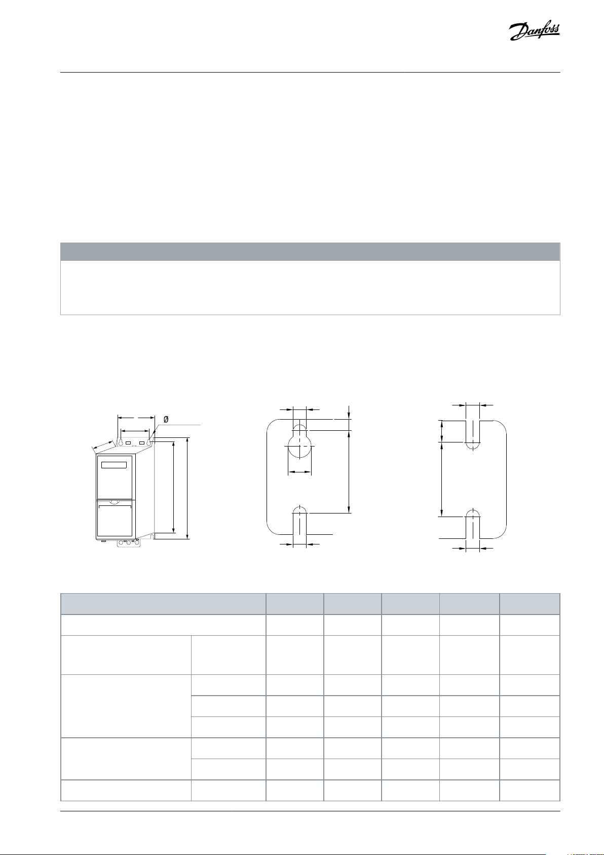
Enclosure Size
H1H2H3H4H5
IP class
IP20
IP20
IP20
IP20
IP20
Power [kW (hp)]
3x380–480 V
0.37–1.5
(0.5–2.0)
2.2–4.0
(3.0–5.0)
5.5–7.5
(7.5–10)
11–15
(15–20)
18.5–22
(25–30)
Height [mm (in)]
A
195 (7.7)
227 (8.9)
255 (10.0)
296 (11.7)
334 (13.1)
A
(1)
273 (10.7)
303 (11.9)
329 (13.0)
359 (14.1)
402 (15.8)
a
183 (7.2)
212 (8.3)
240 (9.4)
275 (10.8)
314 (12.4)
Width [mm (in)]
B
75 (3.0)
90 (3.5)
100 (3.9)
135 (5.3)
150 (5.9)
b
56 (2.2)
65 (2.6)
74 (2.9)
105 (4.1)
120 (4.7)
Depth [mm (in)]
C
168 (6.6)
190 (7.5)
206 (8.1)
241 (9.5)
255 (10)
VLT® Flow Drive FC 111
Operating Guide
Product Overview
3 Product Overview
3.1 Intended Use
The drive is an electronic motor controller that converts AC mains input into a variable AC waveform output. The frequency and
voltage of the output are regulated to control the motor speed or torque. The drive is designed to:
•
Regulate motor speed in response to system feedback or remote commands from external controllers.
•
Monitor system and motor status.
•
Provide motor overload protection.
The drive is designed for industrial and commercial environments in accordance with local laws and standards. Depending on configuration, the drive can be used in standalone applications or form part of a larger system or installation.
N O T I C E
RADIO INTERFERENCE
In a residential environment, this product can cause radio interference.
Take supplementary mitigation measures.
-
Foreseeable misuse
Do not use the drive in applications which are non-compliant with specified operating conditions and environments. Ensure compliance with the conditions specified in chapter Specifications.
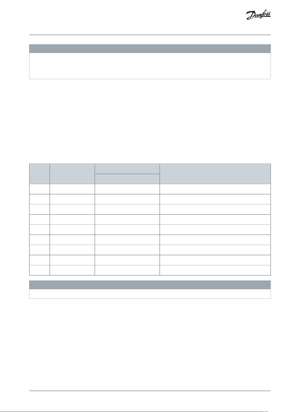
3.2 Power Ratings, Weights, and Dimensions
Illustration 1: Dimensions, Enclosure Sizes H1–H5 & H11–H12
Table 3: Power Ratings, Weights, and Dimensions, Enclosure Sizes H1–H5
AQ304735638503en-000301 / 130R0265 | 9Danfoss A/S © 2021.10
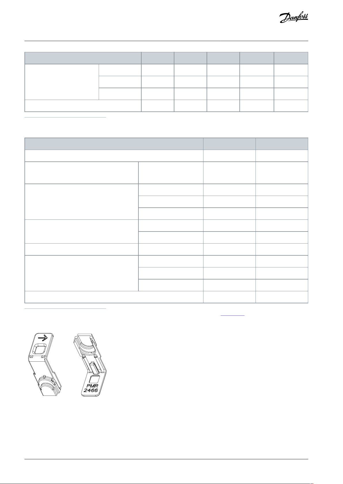
Enclosure Size
H1H2H3H4H5
Mounting hole [mm (in)]
d
9 (0.35)
11 (0.43)
11 (0.43)
12.6 (0.50)
12.6 (0.50)
e
4.5 (0.18)
5.5 (0.22)
5.5 (0.22)
7 (0.28)
7 (0.28)
f
5.3 (0.21)
7.4 (0.29)
8.1 (0.32)
8.4 (0.33)
8.5 (0.33)
Maximum weight [kg (lb)]
2.1 (4.6)
3.4 (7.5)
4.5 (9.9)
7.9 (17.4)
9.5 (20.9)
Enclosure Size
H11
H12
IP class
IP20
IP20
(1)
Power [kW (hp)]
3x380–480 V
30–45
(40–60)
55–90
(70–125)
Height [mm (in)]
A
515 (20.3)
550 (21.7)
A
(2)
545 (21.5)
610.5 (24)
a
495 (19.5)
521 (20.5)
Width [mm (in)]
B
233 (9.2)
308 (12.1)
b
200 (7.9)
270 (10.6)
Depth [mm (in)]
C
241 (9.5)
323 (12.7)
Mounting hole [mm (in)]
d
–
–e8.5 (0.33)
8.5 (0.33)
f
13 (0.5)
17 (0.67)
Maximum weight [kg (lb)]
22.6 (49.8)
40.7 (89.7)
e30bv016.10
VLT® Flow Drive FC 111
Operating Guide
1
Including decoupling plate.
Table 4: Power Ratings, Weights, and Dimensions H11–H12
Product Overview
1
Install the protective cover on the mains and motor terminals after connecting the stripped wire. See Illustration 2.
2
Including decoupling plate.
Illustration 2: Protective Cover
AQ304735638503en-000301 / 130R026510 | Danfoss A/S © 2021.10
e30bu775.10
C
D
b1
B
b D
A
a
E
F
G
(1) (2)
(3)
1
Front view
2
Side view
3
Back view
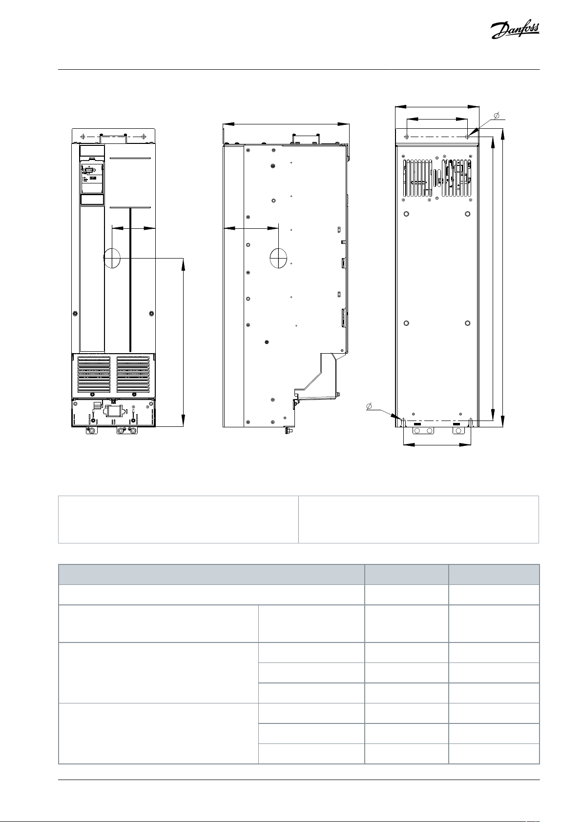
Enclosure Size
H13
H14
IP class
IP20
IP20
Power [kW (hp)]
3x380–480 V
110–160
(150–250)
200–315
(300–450)
Height [mm (in)]
A
889 (35.0)
1096 (43.1)
A
(1)
909 (35.8)
1122 (44.2)
a
844 (33.2)
1051 (41.4)
Width [mm (in)]
B
250 (9.8)
350 (13.8)
b
180 (7.1)
280 (11.0)
b1
200 (7.9)
271 (10.7)
VLT® Flow Drive FC 111
Operating Guide
Product Overview
Illustration 3: Dimensions, Enclosure Sizes H13–H14
Table 5: Power Ratings, Weights, and Dimensions H13–H14
AQ304735638503en-000301 / 130R0265 | 11Danfoss A/S © 2021.10

Enclosure Size
H13
H14
Depth [mm (in)]
C
375 (14.8)
375 (14.8)
Mounting hole [mm (in)]
D
11 (0.4)
11 (0.4)
Center of gravity [mm (in)]
E
128 (5.0)
176 (6.9)
F
495 (19.5)
611 (24.1)
G
148 (5.8)
148 (5.8)
Maximum weight [kg (lb)]
98 (216)
164 (362)
VLT® Flow Drive FC 111
Operating Guide
1
Including decoupling plate.
The dimensions are only for the physical units.
Product Overview
3.3 Check Valve Monitoring
In the pump application system, a damaged check valve is hard to detect, which therefore causes low efficiency of the whole system. VLT® Flow Drive FC 111 can monitor the status of check valves in the system. After enabling the check valve monitoring function via setting parameter 22-04 Check Valve Monitor to [1] Enabled, the drive trips warning 159, Check Valve Failure if a damaged
check valve is detected.
3.4 Dry Pump Detection
In the pump application system, the drive monitors the operation status of the system to detect whether there is water on the
pump's suction side. If the pump runs at maximum speed and consumes little power, then it can be assumed that there is no water
on the pump's suction side. Via setting parameter 22-26 Dry Pump Function to warning or alarm, the drive trips warning/alarm 93, dry
pump if the dry-pump condition is detected.
3.5 End of Curve Detection
In the pump application system, the drive monitors the operation status of the system to detect whether the pressure side of pump
is subject to a major leakage. If the pump runs at maximum speed for a defined time period, but the pressure is below the set point,
then it can be considered to reflect the end-of-curve situation. Via setting parameter 22-50 End of Curve Function to warning or
alarm, the drive trips warning/alarm 94, end of curve if the end-of-curve condition is detected.
3.6 Time-based Functions
In some application scenarios, there are requirements to control the motor running for a specific time, in a specific direction and a
specific speed within a specific time interval. For example, checking the motor status in fire mode or exercising pumps, fans, and
compressors.
For detailed parameter settings, refer to the parameter group 23-** Time-based Functions in the drive's Programming Guide.
AQ304735638503en-000301 / 130R026512 | Danfoss A/S © 2021.10
e30bb634.10
1
2
2
3
4
M
ot
or
U
V
W
-DC
+DC
M
AINS
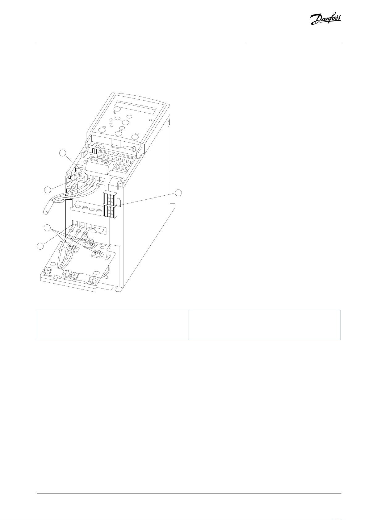
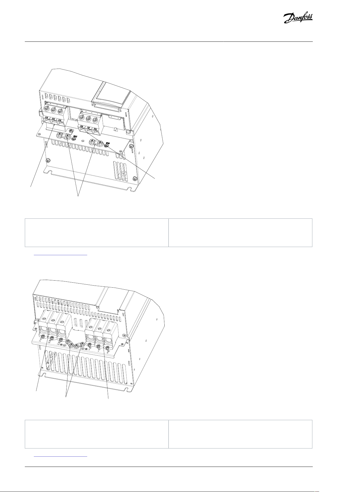
1
Mains
2
Ground
3
Motor
4
Relays
VLT® Flow Drive FC 111
Operating Guide
3.7 Relays and Terminals
3.7.1 Relays and Terminals on Enclosure Sizes H1–H5
Product Overview
Illustration 4: Enclosure Sizes H1–H5 IP20, 380–480 V, 0.37–22 kW (0.5–30 hp)
AQ304735638503en-000301 / 130R0265 | 13Danfoss A/S © 2021.10
1
2
3
e30bu937.10
1
Mains
2
Ground
3
Motor
1
2
3
e30bu938.10
1
Mains
2
Ground
3
Motor
VLT® Flow Drive FC 111
Operating Guide
3.7.2 Relays and Terminals on Enclosure Size H11
Product Overview
Illustration 5: Enclosure Size H11 IP20, 380–480 V, 30–45 kW (40–60 hp)
See 3.8 View of Control Shelf for the relay terminals of H11 drives.
3.7.3 Relays and Terminals on Enclosure Size H12
Illustration 6: Enclosure Size H12 IP20, 380–480 V, 55–90 kW (75–125 hp)
See 3.8 View of Control Shelf for the relay terminals of H12 drives.
AQ304735638503en-000301 / 130R026514 | Danfoss A/S © 2021.10
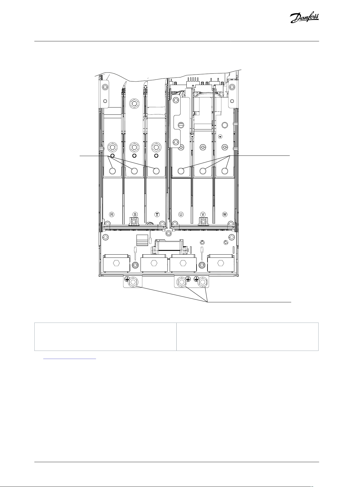
e30bu777 .10
1
2
3
1
Mains
2
Motor
3
Ground
VLT® Flow Drive FC 111
Operating Guide
3.7.4 Relays and Terminals on Enclosure Size H13–H14
Product Overview
Illustration 7: Enclosure Size H13–H14 IP20, 380–480 V, 110–315 kW (150–450 hp)
See 3.8 View of Control Shelf for the relay terminals of H13–H14 drives.
AQ304735638503en-000301 / 130R0265 | 15Danfoss A/S © 2021.10
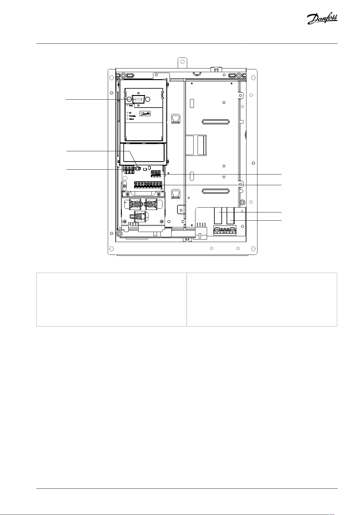
e30bu939.10
1
2
3
4
5
6
7
1
LCP2RS485 termination switch
3
RS485 fieldbus connector
4
Relay 1 on power card
5
Digital I/O and 24 V supply
6
Analog I/O connector
7
Relay 2 on power card
VLT® Flow Drive FC 111
Operating Guide
Product Overview
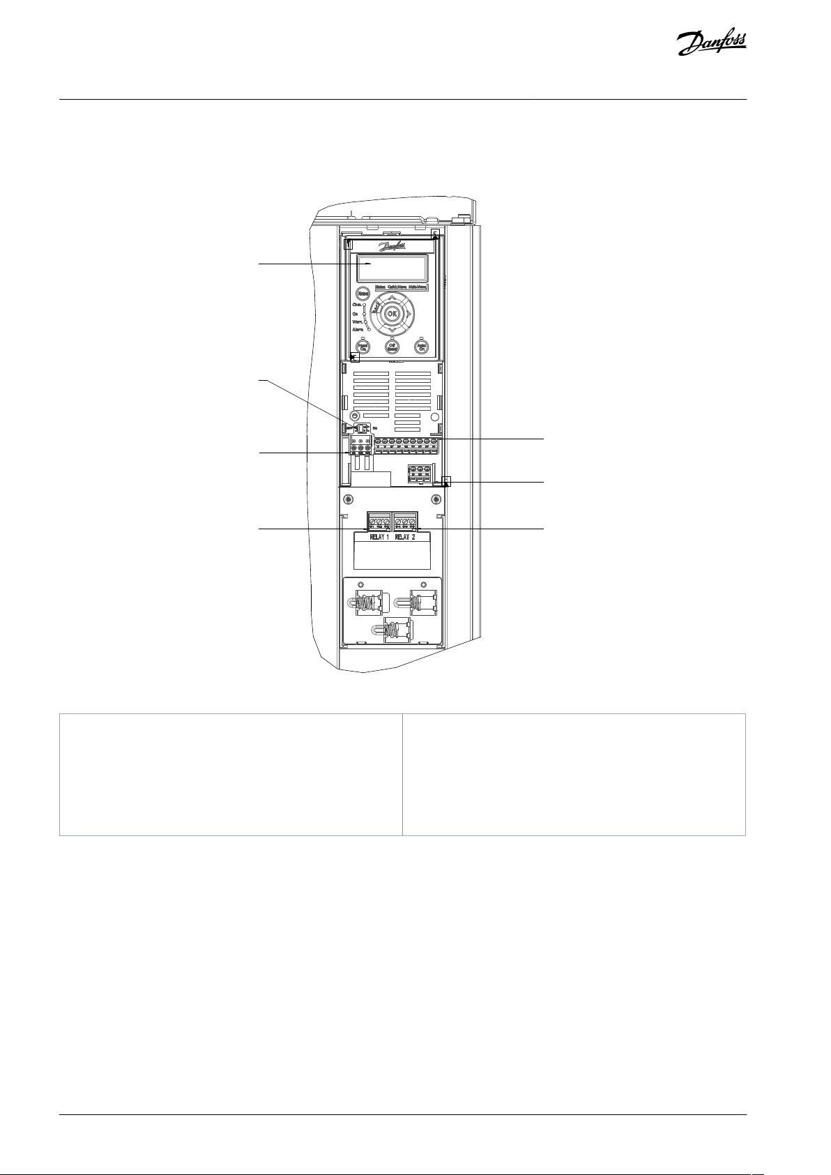
3.8 View of Control Shelf
The control shelf of H11-H14 drives holds the keypad, known as the local control panel or LCP. The control shelf also includes the
control terminals, relays, and various connectors.
Illustration 8: View of Control Shelf in H11–H12
AQ304735638503en-000301 / 130R026516 | Danfoss A/S © 2021.10
e30bu776.10
1
2
3
4
5
6
7
1
LCP connector
2
RS485 termination switch
3
RS485 fieldbus connector
4
Analog I/O connector
5
Digital I/O and 24 V supply
6
Relay 1 on power card
7
Relay 2 on power card
VLT® Flow Drive FC 111
Operating Guide
Product Overview
Illustration 9: View of Control Shelf in H13–H14
AQ304735638503en-000301 / 130R0265 | 17Danfoss A/S © 2021.10
Voltage [V]
Altitude restrictions
380–480
At altitudes above 3000 m (9842 ft), contact Danfoss regarding PELV.
VLT® Flow Drive FC 111
Operating Guide
Mechanical Installation
4 Mechanical Installation
4.1 Storage and Operating Environment
Storage
Store the drive in a dry location. Keep the equipment sealed in its packaging until installation. Refer to the Ambient Conditions
section for recommended ambient temperature.
Periodic forming (capacitor charging) is not necessary during storage unless storage exceeds 12 months.
Operating Environment
N O T I C E
OPERATING ENVIRONMENT
In environments with airborne liquids, particles, or corrosive gases, failure to meet requirements for ambient conditions can re-
duce the lifetime of the drive.
Ensure that the IP/Type rating of the equipment matches the installation environment.
-
Ensure that requirements for air humidity, temperature, and altitude are met.
-
Table 6: Installation at High Altitudes
N O T I C E
CONDENSATION
Moisture can condense on the electronic components and cause short circuits.
Avoid installation in areas subject to frost.
-
Install an optional space heater when the drive is colder than the ambient air.
-
Operating in standby mode reduces the risk of condensation as long as the power dissipation keeps the circuitry free of
-
moisture.
N O T I C E
EXTREME AMBIENT CONDITIONS
Hot or cold temperatures compromise unit performance and longevity.
Do not operate in environments where the ambient temperature exceeds 55 °C (131 °F).
-
The drive can operate at temperatures down to -15 °C (5 °F). However, proper operation at rated load is only guaranteed at
-
0 °C (32 °F) or higher.
Extra air conditioning of the cabinet or installation site is required if temperature exceeds ambient temperature limits.
-
W A R N I N G
EXPLOSIVE ATMOSPHERE
Do not install the drive in a potentially explosive atmosphere.
Install the unit in a cabinet outside of this area.
-
Failure to follow this guideline increases risk of death or serious injury.
-
AQ304735638503en-000301 / 130R026518 | Danfoss A/S © 2021.10
Size
IP class
Power [kW (hp)]
Clearance above/below [mm (in)]
3x380–480 V
H1
IP20
0.37–1.5 (0.5–2.0)
100 (4)
H2
IP20
2.2–4.0 (3.0–5.4)
100 (4)
H3
IP20
5.5–7.5 (7.5–10)
100 (4)
H4
IP20
11–15 (15–20)
100 (4)
H5
IP20
18.5–22 (25–30)
100 (4)
H11
IP20
30–45 (40–60)
200 (7.9)
H12
IP20
55–90 (70–125)
200 (7.9)
H13
IP20/Chassis
110–160 (150–250)
225 (9)
H14
IP20/Chassis
200–315 (300–450)
225 (9)
VLT® Flow Drive FC 111
Operating Guide
Mechanical Installation
N O T I C E
GASES
Aggressive gases, such as hydrogen sulfide, chlorine, or ammonia can damage the electrical and mechanical components.
The unit uses conformal-coated circuit boards to reduce the effects of aggressive gases.
-
When installing the drive in dusty environments, pay attention to the following:
Periodic maintenance
When dust accumulates on electronic components, it acts as a layer of insulation. This layer reduces the cooling capacity of the
components, and the components become warmer. The hotter environment decreases the life of the electronic components. Keep
the heat sink and fans free from dust build-up.
Cooling fans
Fans provide airflow to cool the drive. When fans are exposed to dusty environments, the dust can damage the fan bearings and
cause premature fan failure. Also, dust can accumulate on fan blades causing an imbalance which prevents the fans from properly
cooling the unit.
4.2 Side-by-side Installation
The drive can be mounted side by side but requires the clearance above and below for cooling.
Table 7: Clearance Required for Cooling
With IP21 option kit mounted (available for H1–H5 & H11–H12), a distance of 50 mm (2 in) between the units is required.
N O T I C E
AQ304735638503en-000301 / 130R0265 | 19Danfoss A/S © 2021.10

•
•
•
•
•
•
•
•
•
•
•
•
•
•
Tools
Needed
Receiving/unloading
Installation
H1–H5
–
3 mm flat-edged screwdriver for terminals.
T20 torx head screwdriver for M5 grounding screw.
H11–
H12
I-beam and hooks rated to lift the weight of the drive.
Refer to 3.2 Power Ratings, Weights, and Dimensions.
Crane or other lifting aid to place the unit into position.
Allen key 6# (for M8).
T30 torx head screwdriver for terminals.
T25 torx head screwdriver for M6 grounding screw.
H13–
H14
Drill with a 12 mm (1/2 in) drill bit.
Tape measurer.
Phillips and flat bladed screwdrivers.
Wrench with 7–17 mm metric sockets.
Wrench extensions.
T25 and T50 torx drives.
Sheet metal punch and/or pliers for cable entry plate.
VLT® Flow Drive FC 111
Operating Guide
4.3 Tools Needed
Table 8: Tools Needed
Mechanical Installation
4.4 Installation and Cooling Requirements
OVERHEATING
Improper mounting can result in overheating and reduced performance.
Install the drive according to the installation and cooling requirements.
-
Installation requirements
•
Ensure drive stability by mounting the drive vertically to a solid flat surface.
•
Ensure that the strength of the mounting location supports the drive weight. Ensure that the mounting location allows access
to open the enclosure door. Refer to 3.2 Power Ratings, Weights, and Dimensions.
•
Ensure that there is enough space around the drive for cooling airflow.
•
Place the drive as near to the motor as possible. Keep the motor cables as short as possible. See 10.4.4 Cable Length and Cross-
section.
•
Ensure the location allows for cable entry at the bottom of the drive.
Cooling and airflow requirements
•
Ensure that top and bottom clearance for air cooling is provided, see 4.2 Side-by-side Installation.
•
Consider derating for temperatures starting between 40 °C (104 °F) and 55 °C (131 °F) and elevation 1000 m (3300 ft) above sea
level. See chapter Derating in the Design Guide for detailed information.
•
The drive's maximum heating value could be estimated via the following equation:
Maximumheatingvalue ≈ Power × 1 − Efficiency
For example, the heating value of 110 kW (150 hp) drive could be 2.2 kW. Refer to 10.1.1 3x380–480 V AC for the drive's efficiency at rated load.
•
If multiple drives are installed in 1 cabinet at the same time, the heating value and ventilation volume shall be accumulated.
N O T I C E
AQ304735638503en-000301 / 130R026520 | Danfoss A/S © 2021.10

Power [kW (hp)]
Ventilation volume reference value of the cabinet
CFM
m3/hr
0.37 (0.5)
240.75 (1.0)
471.5 (2.0)
8142.2 (3.0)
9153 (4.0)
13224 (5.0)
19325.5 (7.5)
22377.5 (10)
406811 (15)
73
125
15 (20)
100
170
18.5 (25)
135
229
22 (30)
160
272
30 (40)
178
303
37 (50)
220
374
45 (60)
240
408
55 (70)
257
436
75 (100)
350
595
90 (125)
370
629
110 (150)
414
704
132 (175)
499
849
160 (250)
605
1029
200 (300)
757
1286
250 (350)
887
1507
315 (450)
1118
1900
VLT® Flow Drive FC 111
Operating Guide
••If there are other heating devices, increase the ventilation according to the instructions.
If the dust screen needs to be installed, the air volume needs to be appropriately increased according to the wind resistance
coefficient of the dust screen. For the wind resistance coefficient of dust screen, contact the dust screen supplier.
Table 9: Ventilation Volume Reference Value of the Cabinet
Mechanical Installation
AQ304735638503en-000301 / 130R0265 | 21Danfoss A/S © 2021.10
e30bg512.11
65° min
VLT® Flow Drive FC 111
Operating Guide
Mechanical Installation
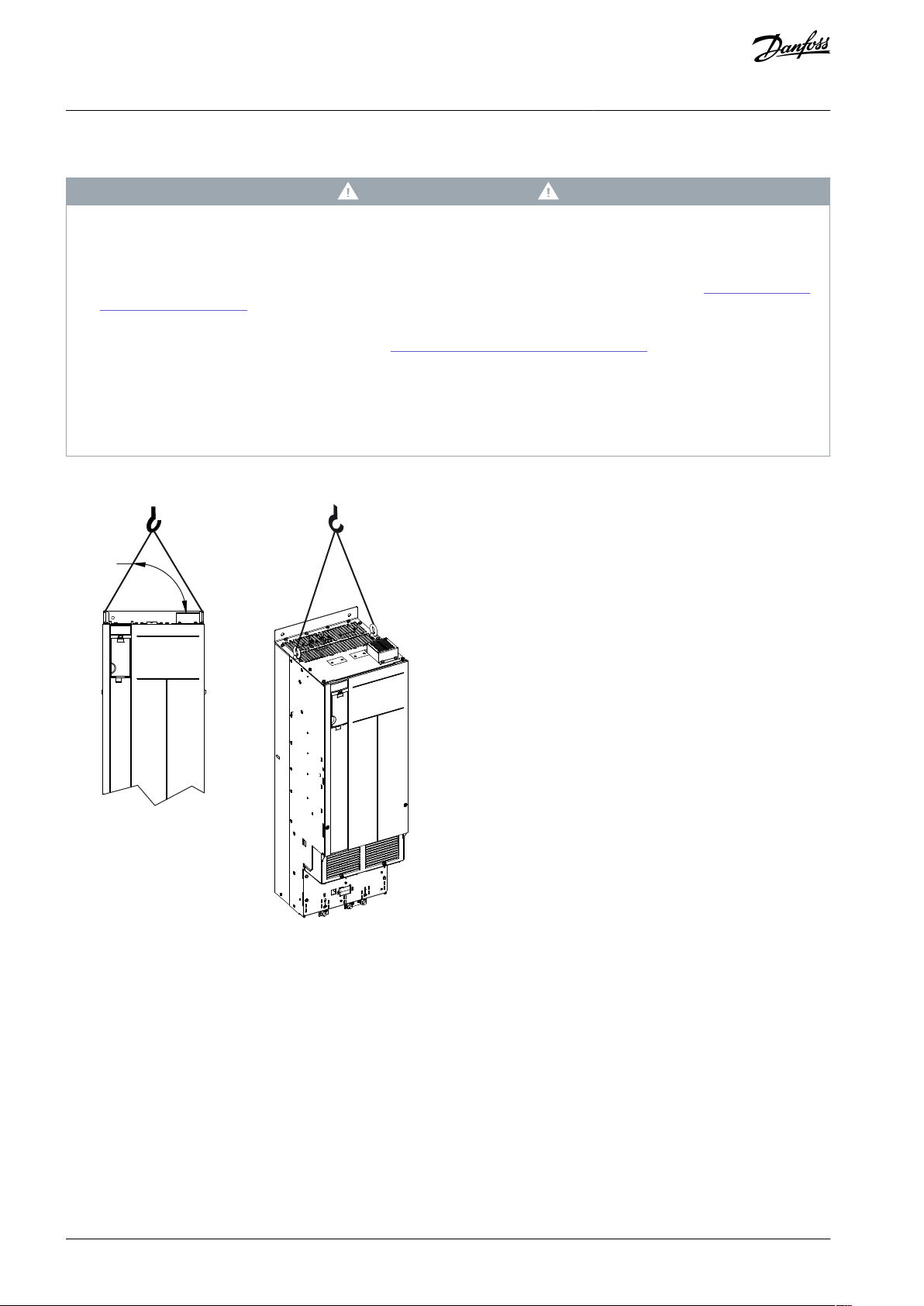
4.5 Lifting the Drive
W A R N I N G
HEAVY LOAD
Unbalanced loads can fall or tip over. Failure to take proper lifting precautions increases risk of death, serious injury, or equip-
ment damage.
Move the unit using a hoist, crane, forklift, or other lifting device with the appropriate weight rating. See 3.2 Power Ratings,
-
Weights, and Dimensions for the weight of the drive.
Failure to locate the center of gravity and correctly position the load can cause unexpected shifting during lifting and trans-
-
port. For measurements and center of gravity, see 3.2 Power Ratings, Weights, and Dimensions.
The angle from the top of the drive module to the lifting cables affects the maximum load force on the cable. This angle
-
must be 65° or greater. Refer to the following illustration. Attach and dimension the lifting cables properly.
Never walk under suspended loads.
-
To guard against injury, wear personal protective equipment such as gloves, safety glasses, and safety shoes.
-
Always lift the drive using the dedicated eye bolts at the top of the drive. See the following illustration.
Illustration 10: Lifting the Drive
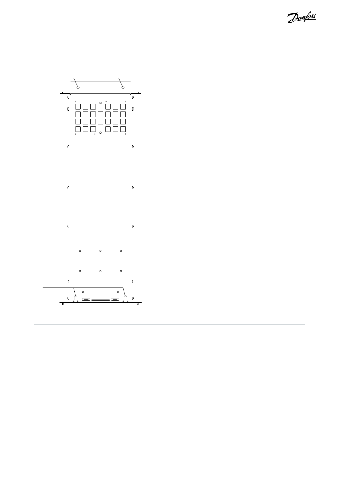
4.6 Wall Mounting the Drive
H13 and H14 are chassis drives intended to be mounted on a wall or on a mounting plate within an enclosure. To wall mount the
drive, use the following steps.
Procedure
1.
Fasten 2 M10 bolts in the wall to align with the fastener slots at the bottom of drive.
2.
Slide the lower fastener slots in the drive over the M10 bolts.
AQ304735638503en-000301 / 130R026522 | Danfoss A/S © 2021.10
1
2
e30bg288.10
1
Top mounting holes
2
Lower fastener slots
VLT® Flow Drive FC 111
Operating Guide
3. Tip the drive against the wall, and secure the top with 2 M10 bolts in the mounting holes.
Example
Mechanical Installation
Illustration 11: Drive-to-wall Mounting Holes
4.7 Creating Cable Openings
After installing H13-H14 drive, create cable openings in the gland plate to accommodate the mains and motor cables. The gland
plate is required to maintain the drive protection rating.
Procedure
AQ304735638503en-000301 / 130R0265 | 23Danfoss A/S © 2021.10

1
e30bf662.10
2
1
Plastic tabs
2
Tabs removed for cable access
VLT® Flow Drive FC 111
Operating Guide
1. Punch out plastic tabs to accommodate the cables.
Illustration 12: Cable Openings in Plastic Gland Plate
Mechanical Installation
AQ304735638503en-000301 / 130R026524 | Danfoss A/S © 2021.10

VLT® Flow Drive FC 111
Operating Guide
Electrical Installation
5 Electrical Installation
5.1 Safety Instructions
See chapter Safety for general safety instructions.
W A R N I N G
INDUCED VOLTAGE
Induced voltage from output motor cables from different drives that are run together can charge equipment capacitors even
with the equipment turned off and locked out. Failure to run output motor cables separately or use shielded cables could result
in death or serious injury.
Run output motor cables separately or use shielded cables.
-
Simultaneously lock out all the drives.
-
W A R N I N G
SHOCK HAZARD
The drive can cause a DC current in the ground conductor and thus result in death or serious injury. Failure to follow the recom-
mendation means that the residual current-operated protective device (RCD) cannot provide the intended protection.
When a residual current-operated protective device (RCD) is used for protection against electrical shock, only an RCD of Type
-
B is allowed on the supply side.
Overcurrent protection
•
Additional protective equipment such as short-circuit protection or motor thermal protection between drive and motor is required for applications with multiple motors.
•
Input fusing is required to provide short circuit and overcurrent protection. If fuses are not factory-supplied, the installer must
provide them. See maximum fuse ratings in chapter Fuses and Circuit Breakers.
Wire type and ratings
•
All wiring must comply with local and national regulations regarding cross-section and ambient temperature requirements.
•
Power connection wire recommendation: Minimum 75 °C (167 °F) rated copper wire.
See 10.4.4 Cable Length and Cross-section for recommended wire sizes and types.
5.2 EMC-compliant Electrical Installation
To ensure EMC-correct electrical installation, observe the following:
•
Use only shielded/armored motor cables and shielded/armored control cables.
•
Ground the shield at both ends.
•
Avoid installation with twisted shield ends (pigtails), because it reduces the shielding effect at high frequencies. Use the cable
clamps provided.
•
Ensure the same potential between the drive and the ground potential of PLC.
•
Use star washers and galvanically conductive installation plates.
AQ304735638503en-000301 / 130R0265 | 25Danfoss A/S © 2021.10

B
a
c
k
OK
Com.
On
Warn.
Alarm
Hand
On
Reset
Auto
On
Menu
Status Quick
Menu
Main
Menu
L1
L2
L3
PE
Minimum 16 mm
2
equalizing cable
Control cables
All cable entries in
one side of the panel
Grounding rail
Cable insulation stripped
Output contactor
Motor cable
Motor, 3 phases and
PLC
Panel
Mains-supply
Minimum 200 mm (7.87 in)
between control
cable, mains cable,
and between mains
motor cable
PLC
protective earth
Reinforced protective earth
e30bb761.13
(6 AWG)
VLT® Flow Drive FC 111
Operating Guide
Electrical Installation
Illustration 13: EMC-compliant Installation
5.3 Electrical Wiring
AQ304735638503en-000301 / 130R026526 | Danfoss A/S © 2021.10

L1
L2
L3
3-phase
power
input
PE
PE
+10 V DC
0-10 V DC-
0-10 V DC-
50 (+10 V OUT)
54 (A IN)
53 (A IN)
55 (COM A IN/OUT)
0/4-20 mA
0/4-20 mA
42 0/4-20 mA A OUT / D OUT
45 0/4-20 mA A OUT / D OUT
18 (D IN)
19 (D IN)
27 (D IN/OUT)
29 (D IN/OUT)
12 (+24 V OUT)
24 V (NPN)
20 (COM D IN)
O V (PNP)
24 V (NPN)
O V (PNP)
24 V (NPN)
O V (PNP)
24 V (NPN)
O V (PNP)
Bus ter.
Bus ter.
RS485
Interface
RS485
(N RS485) 69
(P RS485) 68
(Com RS485 ) 61
(PNP)-Source
(NPN)-Sink
ON=Terminated
OFF=Unterminated
ON
1 2
240 V AC 3 A
Not present on all power sizes
Do not connect shield to 61
01
02
03
relay 1
relay 2
UDC+
UDC-
Motor
U
V
W
e30bd467.12
06
05
04
240 V AC 3 A
Power [kW (hp)]
Torque [Nm (in-lb)]
Enclosure size
IP class
3x380–480 V
Mains
Motor
DC connection
Control terminals
Ground
Relay
H1
IP20
0.37–1.5 (0.5–2.0)
0.8 (7)
0.8 (7)
0.8 (7)
0.5 (4)
0.8 (7)
0.5 (4)
H2
IP20
2.2–4.0 (3.0–5.4)
0.8 (7)
0.8 (7)
0.8 (7)
0.5 (4)
0.8 (7)
0.5 (4)
H3
IP20
5.5–7.5 (7.5–10)
0.8 (7)
0.8 (7)
0.8 (7)
0.5 (4)
0.8 (7)
0.5 (4)
VLT® Flow Drive FC 111
Operating Guide
Electrical Installation
Illustration 14: Basic Wiring Schematic Drawing
There is no access to UDC- and UDC+ on the following units:
-
5.4 Fastener Tightening Torques
Apply the correct torque when tightening fasteners in the locations that are listed in the following tables. Too low or too high torque when fastening an electrical connection results in a bad electrical connection. To ensure correct torque, use a torque wrench.
Table 10: Tightening Torques for Enclosure Sizes H1–H5 & H11–H12, 3x380–480 V
IP20, 380–480 V, 30–315 kW (40–450 hp)
N O T I C E
AQ304735638503en-000301 / 130R0265 | 27Danfoss A/S © 2021.10

Power [kW (hp)]
Torque [Nm (in-lb)]
Enclosure size
IP class
3x380–480 V
Mains
Motor
DC connection
Control terminals
Ground
Relay
H4
IP20
11–15 (15–20)
1.2 (11)
1.2 (11)
1.2 (11)
0.5 (4)
0.8 (7)
0.5 (4)
H5
IP20
18.5–22 (25–30)
1.2 (11)
1.2 (11)
1.2 (11)
0.5 (4)
0.8 (7)
0.5 (4)
H11
IP20
30–45 (40–60)
4.5 (40)
4.5 (40)
–
0.5 (4)
3 (27)
0.5 (4)
H12
IP20
55 (70)
10 (89)
10 (89)
–
0.5 (4)
3 (27)
0.5 (4)
H12
IP20
75 (100)
14 (124)
14 (124)
–
0.5 (4)
3 (27)
0.5 (4)
H12
IP20
90 (125)
24 (212)
(1)
24 (212)
(1)
–
0.5 (4)
3 (27)
0.5 (4)
Location
Bolt size
Torque [Nm (in-lb)]
Mains terminals
M10/M12
19 (168)/37 (335)
Motor terminals
M10/M12
19 (168)/37 (335)
Ground terminals
M8/M10
9.6 (84)/19.1 (169)
Relay terminals
–
0.5 (4)
Door/panel cover
M5
2.3 (20)
Gland plate
M5
2.3 (20)
e30bb612.10
1
1
EMC screw
VLT® Flow Drive FC 111
Operating Guide
1
Cable dimensions >95 mm2.
Table 11: Tightening Torques for Enclosure Sizes H13–H14, 3x380–480 V
Electrical Installation
5.5 IT Mains
C A U T I O N
IT MAINS
Installation on isolated mains source, that is, IT mains.
Ensure that the supply voltage does not exceed 440 V (3x380–480 V units) when connected to mains.
-
For 380–480 V, IP20, 0.37–22 kW (0.5–30 hp) units, open the RFI switch by removing the screw on the side of the drive when at IT
grid.
Illustration 15: IP20, 0.37–22 kW (0.5–30 hp), 380–480 V
AQ304735638503en-000301 / 130R026528 | Danfoss A/S © 2021.10

VLT® Flow Drive FC 111
Operating Guide
Electrical Installation
N O T I C E
If reinserted, use only M3x12 screw.
For 380–480 V, 30–90 kW (40–125 hp) units, set parameter 14-50 RFI Filter to [0] Off when operating in IT mains.
For 380–480 V, 110–315 kW (150–450 hp) units, if the drive is supplied from an isolated mains source (IT mains, floating delta, or
grounded delta) or TT/TN-S mains with grounded leg, the RFI switch is recommended to be turned off via parameter 14-50 RFI Filter
on the drive and parameter 14-50 RFI Filter on the filter. For more details, see IEC 364-3. In the [Off] position, the filter capacitors
between the chassis and the DC link are cut off to avoid damage to the DC link and to reduce the ground capacity currents, according to IEC 61800-3.
If optimum EMC performance is needed, or parallel motors are connected, or the motor cable length is above 25 m (82 ft), Danfoss
recommends setting parameter 14-50 RFI Filter to [On]. It is important to use isolation monitors that are rated for use together with
power electronics (IEC 61557-8).
5.6 Mains and Motor Connection
5.6.1 Introduction
The drive is designed to operate all standard 3-phase asynchronous motors.
Use a shielded/armored motor cable to comply with EMC emission specifications and connect this cable to both the decoupling
•
plate and the motor.
•
Keep the motor cable as short as possible to reduce the noise level and leakage currents.
For further details on mounting the decoupling plate, see the relevant Decoupling Plate Installation Guide.
•
Also see EMC-Correct Installation in the
•
5.2 EMC-compliant Electrical Installation.
5.6.2 Connecting to the Ground
W A R N I N G
LEAKAGE CURRENT HAZARD
Leakage currents exceed 3.5 mA. Failure to ground the drive properly can result in death or serious injury.
Ensure that the minimum size of the ground conductor complies with the local safety regulations for high touch current
-
equipment.
For electrical safety:
•
Ground the drive in accordance with applicable standards and directives.
•
Use a dedicated ground wire for input power, motor power, and control wiring.
•
Do not ground 1 drive to another in a daisy chain fashion.
•
Keep the ground wire connections as short as possible.
•
Follow motor manufacturer wiring requirements.
•
Minimum cable cross-section: 10 mm2 (8 AWG) Cu or 16 mm2 (6 AWG) Al (or 2 rated ground wires terminated separately).
•
Tighten the terminals in accordance with the information provided in 5.4 Fastener Tightening Torques.
For EMC-compliant installation
•
Establish electrical contact between the cable shield and the drive enclosure by using metal cable glands or by using the clamps
provided on the equipment.
•
Reduce burst transient by using high-strand wire.
•
Do not use twisted shield ends (pigtails).
AQ304735638503en-000301 / 130R0265 | 29Danfoss A/S © 2021.10

e30bv020.10
1
2
1
Ferrule without plastic sleeve
2
Ferrule with plastic sleeve
VLT® Flow Drive FC 111
Operating Guide
Electrical Installation
N O T I C E
POTENTIAL EQUALIZATION
There is a risk of burst transient when the ground potential between the drive and the control system is different.
Install equalizing cables between the system components. Recommended cable cross-section: 16 mm2 (6 AWG).
-
5.6.3 Connecting the Motor
W A R N I N G
INDUCED VOLTAGE
Induced voltage from output motor cables that run together can charge equipment capacitors, even with the equipment turned
off and locked out/tagged out. Failure to run output motor cables separately or to use shielded cables could result in death or
serious injury.
Run output motor cables separately or use shielded cables.
-
Simultaneously lock out/tag out all the drives.
-
•
Comply with local and national electrical codes for cable sizes. For maximum wire sizes, see 10.4.4 Cable Length and Cross-
section.
•
Follow motor manufacturer wiring requirements.
•
Motor wiring knockouts or access panels are provided at the base of IP21 and higher units.
•
Do not wire a starting or pole-changing device (for example, Dahlander motor or slip ring asynchronous motor) between the
drive and the motor.
Procedure
1.
For H12 drives, remove the protective covers using a screwdriver before connecting the stripped wire.
2.
For H1–H5 and H13–H14 drives, strip a section of the outer cable insulation.
3.
For H11-H12 drives:
a.
If ferrule without plastic sleeve is used, strip 16–17 mm (0.63–0.67 in) section of the outer cable insulation.
b.
If ferrule with plastic sleeve is used, strip a section of the outer cable insulation.
Illustration 16: Ferrule with/without Plastic Sleeve
AQ304735638503en-000301 / 130R026530 | Danfoss A/S © 2021.10

e30bv021.10
1
2
3
1
Terminal locating slot
2
Cover positioning pins
3
Cable block slice
VLT® Flow Drive FC 111
Operating Guide
4.
Position the stripped wire under the cable clamp, establishing mechanical fixation and electrical contact between the cable
shield and ground.
5.
Connect the ground wire to the nearest grounding terminal in accordance with the grounding instructions provided in
5.6.2 Connecting to the Ground.
6.
Connect the 3-phase motor wiring to terminals U, V, and W.
7.
Tighten the terminals in accordance with the information provided in 5.4 Fastener Tightening Torques.
8.
For H12 drives, install the protective cover on the terminals.
a.
Cut the cable block slice according to the wire size.
b.
Put the positioning pin to the terminal locating slot.
Electrical Installation
Illustration 17: Installing Protective Covers, H12
5.6.4 Connecting the AC Mains
•
Size the wiring according to the input current of the drive. For maximum wire sizes, see 10.1.1 3x380–480 V AC.
•
Comply with local and national electrical codes for cable sizes.
Procedure
1.
For H12 drives, remove the protective covers using a screwdriver before connecting the stripped wire.
2.
For H1–H5 and H13–H14 drives, strip a section of the outer cable insulation.
3.
For H11-H12 drives, see the Illustration Ferrule with/without Plastic Sleeve in
a.
If ferrule without plastic sleeve is used, strip 16–17 mm (0.63–0.67 in) section of the outer cable insulation.
b.
If ferrule with plastic sleeve is used, strip a section of the outer cable insulation.
4.
Position the stripped wire under the cable clamp, establishing mechanical fixation and electrical contact between the cable
shield and ground.
5.
Connect the ground wire to the nearest grounding terminal in accordance with the grounding instructions provided in
5.6.2 Connecting to the Ground.
6.
For H1-H5 & H11-H12 drives, connect the 3-phase AC input power wiring to terminals L1, L2, and L3.
7.
For H13-H14 drives, connect the 3-phase AC input power wiring to terminals R, S, and T.
8.
When supplied from an isolated mains source (IT mains or floating delta) or TT/TN-S mains with a grounded leg (grounded
delta), ensure that parameter 14-50 RFI Filter is set to [0] Off to avoid damage to the DC link and to reduce ground capacity
currents.
9.
Tighten the terminals in accordance with the information provided in 5.4 Fastener Tightening Torques.
10.
For H12 drives, install the protective cover on the terminals, see the Illustration Installing Protective Covers, H12 in 5.6.3 Con-
necting the Motor.
a.
Cut the cable block slice according to the wire size.
b.
Put the positioning pin to the terminal locating slot.
5.6.3 Connecting the Motor.
AQ304735638503en-000301 / 130R0265 | 31Danfoss A/S © 2021.10

3x380–480 V IP20 [kW (hp)]
Maximum fuse
0.37 (0.5)
gG-10
0.75 (1.0)
gG-10
1.5 (2.0)
gG-10
2.2 (3.0)
gG-16
3.0 (4.0)
gG-16
4.0 (5.4)
gG-16
5.5 (7.5)
gG-25
7.5 (10)
gG-25
11 (15)
gG-50
15 (20)
gG-50
18.5 (25)
gG-63
22 (30)
gG-63
30 (40)
gG-125
37 (50)
gG-125
45 (60)
gG-125
55 (70)
aR-250
VLT® Flow Drive FC 111
Operating Guide
Electrical Installation
5.7 Fuses and Circuit Breakers
5.7.1 Branch Circuit Protection
To prevent fire hazards, protect the branch circuits in an installation, switch gear, machines, and so on, against short circuits and
overcurrent. Follow national and local regulations.
5.7.2 Short-circuit Protection
Danfoss recommends using the fuses and circuit breakers listed in this chapter to protect service personnel or other equipment in
case of an internal failure in the unit or a short circuit on the DC link. The drive provides full short-circuit protection in case of a short
circuit on the motor.
5.7.3 Overcurrent Protection
Provide overload protection to avoid overheating of the cables in the installation. Overcurrent protection must always be carried
out according to local and national regulations. Design circuit breakers and fuses for protection in a circuit capable of supplying a
maximum of 100000 A
(symmetrical), 480 V maximum.
rms
5.7.4 CE Compliance
To ensure compliance with IEC 61800-5-1, use the circuit breakers or fuses listed in this chapter. Circuit breakers must be designed
for protection in a circuit capable of supplying a maximum of 10000 A
(symmetrical), 480 V maximum.
rms
5.7.5 Recommendation of Fuses
N O T I C E
In the event of malfunction, failure to follow the protection recommendation may result in damage to the drive.
Table 12: Recommendation of Fuses
AQ304735638503en-000301 / 130R026532 | Danfoss A/S © 2021.10

75 (100)
aR-250
90 (125)
aR-250
110 (150)
aR-315
132 (175)
aR-350
160 (250)
aR-400
200 (300)
aR-500
250 (350)
aR-630
315 (450)
aR-800
Model
Fuse Options
Bussman
Littelfuse
Littelfuse
Bussman
Siba
Ferraz-Shawmut
Ferraz-Shawmut(Europe)
P110
170M2619
LA50QS300-4
L50S-300
FWH-300A
20 189 20.315
A50QS300-4
6,9URD31D08A0315
P132
170M2620
LA50QS350-4
L50S-350
FWH-350A
20 189 20.350
A50QS350-4
6,9URD31D08A0350
P160
170M2621
LA50QS400-4
L50S-400
FWH-400A
20 189 20.400
A50QS400-4
6,9URD31D08A0400
P200
170M4015
LA50QS500-4
L50S-500
FWH-500A
20 189 20.550
A50QS500-4
6,9URD31D08A0550
P250
170M4016
LA50QS600-4
L50S-600
FWH-600A
20 189 20.630
A50QS600-4
6,9URD31D08A0630
P315
170M4017
LA50QS800-4
L50S-800
FWH-800A
20 189 20.800
A50QS800-4
6,9URD32D08A0800
e30bd331.11
VLT® Flow Drive FC 111
Operating Guide
Table 13: H13–H14 Power/semiconductor Fuse Options, 380–480 V
Electrical Installation
5.8 Control Terminals
Remove the terminal cover (H1-H5 & H11-H12) or the cradle cover (H13-H14) to access the control terminals.
H1-H5 & H11-H12
Use a flat-edged screwdriver to push down the lock lever of the terminal cover under the LCP, then remove the terminal cover as
shown in Illustration 18.
Illustration 18: Removing the Terminal Cover
H13-H14
Press the tips of the cradle cover inwards as shown in Illustration 19, and then lift the cradle cover up.
AQ304735638503en-000301 / 130R0265 | 33Danfoss A/S © 2021.10

e30bu793.10
e30bv024.10
12 20 55
181927 29 42 54
45 50 53
DIGI IN
616869
N
P
COMM. GND
+24 V
GND
GND
10 V OUT
10 V/20 mA IN
0/4-20 mA A OUT/DIG OUT
BUS TER.
OFF
ON
DIGI IN
DIGI IN/OUT
DIGI IN/OUT
0/4-20 mA A OUT/DIG OUT
10 V/20 mA IN
VLT® Flow Drive FC 111
Operating Guide
Electrical Installation
Illustration 19: Removing the Cradle Cover
All the drive control terminals are shown in Illustration 20. Applying start (terminal 18), connection between terminals 12-27, and an
analog reference (terminal 53 or 54, and 55) make the drive run.
The digital input mode of terminal 18, 19, and 27 is set in parameter 5-00 Digital Input Mode (PNP is default value). Digital input 29
mode is set in parameter 5-03 Digital Input 29 Mode (PNP is default value).
Illustration 20: Control Terminals
5.9 Acoustic Noise or Vibration
If the motor or the equipment driven by the motor, for example, a fan, is making noise or vibrations at certain frequencies, configure
the following parameters or parameter groups to reduce or eliminate the noise or vibrations:
•
Parameter group 4-6* Speed Bypass.
•
Set parameter 14-03 Overmodulation to [0] Off.
•
Switching pattern and switching frequency parameter group 14-0* Inverter Switching.
•
Parameter 1-64 Resonance Dampening.
AQ304735638503en-000301 / 130R026534 | Danfoss A/S © 2021.10

e30bu792.11
B
a
c
k
Com.
4-10 Motor Speed Direction
[2] Both directions
Setup 1
A
B
1
12
13 14 15
11
11
10
9
8
7
6
5
4
3
2
C
D
Status
Main
Menu
Quick
Menu
Hand
On
OK
Menu
Off
Reset
Auto
On
Alarm
Warn.
On
11
B
C
D
A
13 14 15
12
11
11
5
4
10
6
7
8
9
1
2
11
LCP 32 LCP 31
4-10 Motor Speed Dir
ection
[2] Both directions
Status
Quick
Menu
Main
Menu
Menu
OK
Com.
On
Warn.
Alarm
Hand
On
Off
Reset
Auto
On
Back
1
Parameter number and name.
2
Parameter value.
3
The setup number shows the active setup and the edit setup.
For LCP 32, the setup number only shows in Status menu, the number outside the brackets is active setup, and the number
inside the brackets is edit setup. For example, 1(2) means 1 is the active setup, and 2 is the edit setup.
For LCP 31, if the same setup acts as both active and edit setup, only that setup number is shown (factory setting). When the
active and the edit setup differ, both numbers are shown in the display (setup 12). The number flashing indicates the edit
setup.
4
Motor direction is shown to the bottom left of the display – indicated by a small arrow pointing either clockwise or counterclockwise.
5
The triangle indicates if the LCP is in Status, Quick Menu, or Main Menu.
VLT® Flow Drive FC 111
Operating Guide
6 Programming
6.1 Local Control Panel (LCP)
The LCP is divided into 4 functional sections.
•
A. Display
•
B. Menu key
•
C. Navigation keys and indicator lights
•
D. Operation keys and indicator lights
Programming
Illustration 21: Local Control Panel (LCP)
A. Display
The LCD-display of LCP 32 is illuminated with 3 alphanumeric lines, while the LCD-display of LCP 31 is illuminated with 2 alphanumeric lines. All data is shown on the LCP. The Table 14 describes the information that can be read from the display.
Table 14: Legend to Section A, Illustration 3
B. Menu key
Press [Menu] to select among Status, Quick Menu, or Main Menu.
C. Navigation keys and indicator lights
AQ304735638503en-000301 / 130R0265 | 35Danfoss A/S © 2021.10

6
Com. (yellow indicator): Flashes during bus communication.
7
On (green indicator): Shows the power-on status.
8
Warn. (yellow indicator): Indicates a warning.
9
Alarm (red indicator): Indicates an alarm.
10
[Back]: For moving to the previous step or layer in the navigation structure.
11
[▵], [▿], and [▹]: For navigating among parameter groups and parameters, and within parameters. They can also be used for
setting local reference.
12
[OK]: For selecting a parameter and for accepting changes to parameter settings.
13
[Hand On]: Starts the motor and enables control of the drive via the LCP.
N O T I C E
[2] Coast inverse is the default option for parameter 5-12 Terminal 27 Digital Input. If there is no 24 V supply to terminal 27,
[Hand On] does not start the motor. Connect terminal 12 to terminal 27.
14
[Off/Reset]: Stops the compressor (Off). If in alarm mode, the alarm is reset.
15
[Auto On]: The drive is controlled either via control terminals or serial communication.
FC
+24 V (OUT)
DIG IN
DIG IN
DIG IN
DIG IN
COM DIG IN
A OUT / D OUT
A OUT / D OUT
18
19
27
29
42
55
50
53
54
20
12
01
02
03
04
05
06
R2
R1
+
0–10 V
Start
+10 V (OUT)
A IN
A IN
COM IN/OUT
45
Reference
e30bb674.11
VLT® Flow Drive FC 111
Operating Guide
Table 15: Legend to Section C, Illustration 3
D. Operation keys and indicator lights
Table 16: Legend to Section D, Illustration 3
Programming
6.2 Set-up Wizard
6.2.1 Setup Wizard Introduction
The built-in wizard menu guides the installer through the setup of the drive in a clear and structured manner for open-loop and
closed-loop applications, and for quick motor settings.
Illustration 22: Drive Wiring
The wizard can always be accessed again through the quick menu. Press [OK] to start the wizard. Press [Back] to return to the status
view.
AQ304735638503en-000301 / 130R026536 | Danfoss A/S © 2021.10

Power kW/50 H z
Motor Power
Motor Voltage
Motor Frequency
Motor Current
Motor nominal speed
if
Select Regional Settings
... the Wizard starts
200-240V/50Hz/Delta
Grid Type
Induction motor
Asynchronous
Motor Type
Motor current
Motor nominal speed
Motor Cont. Rated Torque
Stator resistance
Motor poles
Back EMF at 1000 rpm
Motor type = IPM
Motor type = SPM
d-axis Inductance Sat. (LdSat)
[0]
[0]
3.8
A
3000
RPM
5.4
Nm
0.65
Ohms
8
Start Mode
Rotor Detection
[0]
Position Detection Gain
%
Off
100
Locked Rotor Detection
[0]
s
Locked Rotor Detection Time[s]
0.10
57
V
5
mH
q-axis Inductance (Lq)
5
mH
1.10
kW
400
V
50
Hz
Max Output Frequency
65
Hz
Motor Cable Length
50
m
4.66
A
1420
RPM
[0]
PM motor
Set Motor Speed low Limit
Hz
Set Motor Speed high Limit
Hz
Set Ramp 1 ramp-up time
s
Set Ramp 1 ramp-down Time
s
Active Flying start ?
Disable
Set T53 low Voltage
V
Set T53 high Voltage
V
Set T53 Low Current
A
Set T53 High Current
A
Voltage
AMA Failed
AMA Failed
Automatic Motor Adaption
Auto Motor Adapt OK
Press OK
Select Function of Relay 2
No function
Off
Select Function of Relay 1
[0] No function
Set Max Reference
Hz
Hz
Set Min Reference
AMA running
-----
Do AMA
(Do not AMA)
AMA OK
[0]
[0]
[0]
Select T53 Mode
Current
Current
Motor type = Induction
Motor type = PM motor
0000
0050
0010
0010
[0]
[0]
04.66
13.30
0050
0220
0000
0050
The next screen is
the Wizard screen.
Power-up Screen
e30bu808.12
q-axis Inductance Sat. (LqSat)
5
mH
Current at Min Inductance for d-axis
100
%
Current at Min Inductance for q-axis
100
%
d-axis Inductance (Lq)
5
mH
... the Wizard starts
Or
0-** FC-xxx Wizard
2-** Motor Setup
Status
Quick
Menu
Main
Menu
Menu
OK
Com.
On
Warn.
Alarm
Hand
On
Off
Reset
Auto
On
Back
1-** Closed Loop Set
0.0 Hz
Auto On
Status
Quick
Menu
Main
Menu
Menu
OK
Com.
On
Warn.
Alarm
Hand
On
Off
Reset
Auto
On
Back
0.000 kW
1 (1)
Menu
OK
VLT® Flow Drive FC 111
Operating Guide
6.2.2 Setup Wizard for Open-loop Applications
Programming
Illustration 23: Setup Wizard for Open-loop Applications
AQ304735638503en-000301 / 130R0265 | 37Danfoss A/S © 2021.10

•
•
•
•
•
•
•
•
•
•
•
•
•
•
•
•
•
•
•
•
•
•
•
•
•
•
Parameter
Option
Default
Usage
Parameter 0-03
Regional Settings
[0] International
[1] US
[0] International
–
Parameter 0-06
GridType
[10] 380–440 V/50 Hz/IT-grid
[11] 380–440 V/50 Hz/Delta
[12] 380–440 V/50 Hz
[20] 440–480 V/50 Hz/IT-grid
[21] 440–480 V/50 Hz/Delta
[22] 440–480 V/50 Hz
[110] 380–440 V/60 Hz/IT-grid
[111] 380–440 V/60 Hz/Delta
[112] 380–440 V/60 Hz
[120] 440–480 V/60 Hz/IT-grid
[121] 440–480 V/60 Hz/Delta
[122] 440–480 V/60 Hz
Size related
Select the operating mode for restart after reconnection of
the drive to mains voltage after power down.
N O T I C E
Compared to 380–440 V groups, when selecting 440–
480 V groups, the rated current decreases accordingly.
Parameter 1-10
Motor Construction
*[0] Asynchron
[1] PM, non-salient SPM
[3] PM, salient IPM
[0] Asynchron
Setting the parameter value might change these parameters:
Parameter 1-01 Motor Control Principle.
Parameter 1-03 Torque Characteristics.
Parameter 1-08 Motor Control Bandwidth.
Parameter 1-14 Damping Gain.
Parameter 1-15 Low Speed Filter Time Const.
Parameter 1-16 High Speed Filter Time Const.
Parameter 1-17 Voltage Filter Time Const.
Parameter 1-20 Motor Power.
Parameter 1-22 Motor Voltage.
Parameter 1-23 Motor Frequency.
Parameter 1-24 Motor Current.
Parameter 1-25 Motor Nominal Speed.
Parameter 1-26 Motor Cont. Rated Torque.
Parameter 1-30 Stator Resistance (Rs).
Parameter 1-33 Stator Leakage Reactance (X1).
Parameter 1-35 Main Reactance (Xh).
Parameter 1-37 d-axis Inductance (Ld).
Parameter 1-38 q-axis Inductance (Lq).
Parameter 1-39 Motor Poles.
Parameter 1-40 Back EMF at 1000 RPM.
Parameter 1-44 d-axis Inductance Sat. (LdSat).
Parameter 1-45 q-axis Inductance Sat. (LqSat).
Parameter 1-46 Position Detection Gain.
Parameter 1-48 Current at Min Inductance for d-axis.
Parameter 1-49 Current at Min Inductance for q-axis.
Parameter 1-66 Min. Current at Low Speed.
VLT® Flow Drive FC 111
Operating Guide
Table 17: Setup Wizard for Open-loop Applications
Programming
AQ304735638503en-000301 / 130R026538 | Danfoss A/S © 2021.10

•
•
•
•
•
•
•
•
•
•
•
•
•
•
•
Parameter
Option
Default
Usage
Parameter 1-70 PM Start Mode.
Parameter 1-72 Start Function.
Parameter 1-73 Flying Start.
Parameter 1-80 Function at Stop.
Parameter 1-82 Min Speed for Function at Stop [Hz].
Parameter 1-90 Motor Thermal Protection.
Parameter 2-00 DC Hold/Motor Preheat Current.
Parameter 2-01 DC Brake Current.
Parameter 2-02 DC Braking Time.
Parameter 2-04 DC Brake Cut In Speed.
Parameter 2-10 Brake Function.
Parameter 4-14 Motor Speed High Limit [Hz].
Parameter 4-19 Max Output Frequency.
Parameter 4-58 Missing Motor Phase Function.
Parameter 14-65 Speed Derate Dead Time Compensation.
Parameter 1-20
Motor Power
0.18–110 kW/0.25–150 hp
Size related
Enter the motor power from the nameplate data.
Parameter 1-22
Motor Voltage
50–1000 V
Size related
Enter the motor voltage from the nameplate data.
Parameter 1-23
Motor Frequency
20–400 Hz
Size related
Enter the motor frequency from the nameplate data.
Parameter 1-24
Motor Current
0.01–1000.00 A
Size related
Enter the motor current from the nameplate data.
Parameter 1-25
Motor Nominal
Speed
50–9999 RPM
Size related
Enter the motor nominal speed from the nameplate data.
Parameter 1-26
Motor Cont.
Rated Torque
0.1–1000.0 Nm
Size related
This parameter is available when parameter 1-10 Motor Con-
struction is set to options that enable permanent motor
mode.
N O T I C E
Changing this parameter affects the settings of other pa-
rameters.
Parameter 1-29
Automatic Motor Adaption
(AMA)
See parameter 1-29 Automatic
Motor Adaption (AMA).
Off
Performing an AMA optimizes motor performance.
Parameter 1-30
Stator Resistance (Rs)
0.000–99.990 Ω
Size related
Set the stator resistance value.
Parameter 1-37
d-axis Inductance (Ld)
0.000–1000.000 mH
Size related
Enter the value of the d-axis inductance. Obtain the value
from the permanent magnet motor datasheet.
VLT® Flow Drive FC 111
Operating Guide
Programming
AQ304735638503en-000301 / 130R0265 | 39Danfoss A/S © 2021.10

Parameter
Option
Default
Usage
Parameter 1-38
q-axis Inductance (Lq)
0.000–1000.000 mH
Size related
Enter the value of the q-axis inductance.
Parameter 1-39
Motor Poles
2–100
4
Enter the number of motor poles.
Parameter 1-40
Back EMF at
1000 RPM
10–9000 V
Size related
Line-line RMS back EMF voltage at 1000 RPM.
Parameter 1-42
Motor Cable
Length
0–100 m
50 m
Enter the motor cable length.
Parameter 1-44
d-axis Inductance Sat.
(LdSat)
0.000–1000.000 mH
Size related
This parameter corresponds to the inductance saturation of
Ld. Ideally, this parameter has the same value as parameter
1-37 d-axis Inductance (Ld). However, if the motor supplier
provides an induction curve, enter the induction value,
which is 200% of the nominal current.
Parameter 1-45
q-axis Inductance Sat.
(LqSat)
0.000–1000.000 mH
Size related
This parameter corresponds to the inductance saturation of
Lq. Ideally, this parameter has the same value as parameter
1-38 q-axis Inductance (Lq). However, if the motor supplier
provides an induction curve, enter the induction value,
which is 200% of the nominal current.
Parameter 1-46
Position Detection Gain
20–200%
100%
Adjusts the height of the test pulse during position detection at start.
Parameter 1-48
Current at Min
Inductance for
d-axis
20–200%
100%
Enter the inductance saturation point.
Parameter 1-49
Current at Min
Inductance for
q-axis
20–200%
100%
This parameter specifies the saturation curve of the d- and qinductance values. From 20–100% of this parameter, the inductances are linearly approximated due to parameter 1-37
d-axis Inductance (Ld), parameter 1-38 q-axis Inductance (Lq),
parameter 1-44 d-axis Inductance Sat. (LdSat), and parameter
1-45 q-axis Inductance Sat. (LqSat).
Parameter 1-70
PM Start Mode
[0] Rotor Detection
[1] Parking
[3] Rotor Last Position
[1] Parking
Select the PM motor start mode.
Parameter 1-73
Flying Start
[0] Disabled
[1] Enabled
[0] Disabled
Select [1] Enabled to enable the drive to catch a motor spinning due to mains drop-out. Select [0] Disabled if this function is not required. When this parameter is set to [1] Ena-
bled, parameter 1-71 Start Delay and parameter 1-72 Start
Function are not functional. Parameter 1-73 Flying Start is ac-
tive in VVC+ mode only.
Parameter 3-02
Minimum Reference
-4999.000–4999.000
0
The minimum reference is the lowest value obtainable by
summing all references.
Parameter 3-03
Maximum Reference
-4999.000–4999.000
50
The maximum reference is the lowest obtainable by summing all references.
VLT® Flow Drive FC 111
Operating Guide
Programming
AQ304735638503en-000301 / 130R026540 | Danfoss A/S © 2021.10

Parameter
Option
Default
Usage
Parameter 3-41
Ramp 1 Ramp
Up Time
0.01–3600.00 s
Size related
If induction motor is selected, the ramp-up time is from 0 to
rated parameter 1-23 Motor Frequency. If PM motor is selected, the ramp-up time is from 0 to parameter 1-25 Motor
Nominal Speed.
Parameter 3-42
Ramp 1 Ramp
Down Time
0.01–3600.00 s
Size related
For induction motors, the ramp-down time is from rated pa-
rameter 1-23 Motor Frequency to 0. For PM motors, the rampdown time is from parameter 1-25 Motor Nominal Speed to 0.
Parameter 4-12
Motor Speed
Low Limit [Hz]
0.0–400.0 Hz
0 Hz
Enter the minimum limit for low speed.
Parameter 4-14
Motor Speed
High Limit [Hz]
0.0–400.0 Hz
100 Hz
Enter the maximum limit for high speed.
Parameter 4-19
Max Output
Frequency
0.0–400.0 Hz
100 Hz
Enter the maximum output frequency value. If parameter
4-19 Max Output Frequency is set lower than parameter 4-14
Motor Speed High Limit [Hz], parameter 4-14 Motor Speed High
Limit [Hz] is set equal to parameter 4-19 Max Output Frequency automatically.
Parameter 5-40
Function Relay
See parameter 5-40 Function
Relay.
[9] Alarm
Select the function to control output relay 1.
Parameter 5-40
Function Relay
See parameter 5-40 Function
Relay.
[5] Drive running
Select the function to control output relay 2.
Parameter 6-10
Terminal 53
Low Voltage
0.00–10.00 V
0.07 V
Enter the voltage that corresponds to the low reference value.
Parameter 6-11
Terminal 53
High Voltage
0.00–10.00 V
10 V
Enter the voltage that corresponds to the high reference value.
Parameter 6-12
Terminal 53
Low Current
0.00–20.00 mA
4 mA
Enter the current that corresponds to the low reference value.
Parameter 6-13
Terminal 53
High Current
0.00–20.00 mA
20 mA
Enter the current that corresponds to the high reference value.
Parameter 6-19
Terminal 53
mode
[0] Current
[1] Voltage
[1] Voltage
Select if terminal 53 is used for current or voltage input.
Parameter
30-22 Locked
Rotor Detection
[0] Off
[1] On
[0] Off
–
Parameter
30-23 Locked
Rotor Detection
Time [s]
0.05–1 s
0.10 s
–
VLT® Flow Drive FC 111
Operating Guide
Programming
AQ304735638503en-000301 / 130R0265 | 41Danfoss A/S © 2021.10

6-29 Terminal 54 Mode
[1]
Voltage
6-25 T54 high Feedback
0050
Hz
20-94 PI integral time
0020.00
s
Current
Voltage
This dialog is forced to be set to
[1] Analog input 54
20-00 Feedback 1 source
[1]
Analog input 54
3-10 Preset reference [0]
0.00
3-03 Max Reference
50.00
3-02 Min Reference
0.00
Induction motor
1-73 Flying Start
[0]
No
1-22 Motor Voltage
400
V
1-24 Motor Current
04.66
A
1-25 Motor nominal speed
1420
RPM
3-41 Ramp 1 ramp-up time
0010
s
3-42 Ramp1 ramp-down time
0010
s
0-06 Grid Type
4-12 Motor speed low limit
0016
Hz
4-14 Motor speed high limit
0050
Hz
e30bc402.16
1-20 Motor Power
1.10
kW
1-23 Motor Frequency
50
Hz
6-22 T54 Low Current
A
6-24 T54 low Feedback
0016
Hz
6-23 T54 high Current
13.30
A
6-25 T54 high Feedback
0050
0.01
s
20-81 PI Normal/Inverse Control
[0]
Normal
20-83 PI Normal/Inverse Control
0050
Hz
20-93 PI Proportional Gain
00.50
1-29 Automatic Motor Adaption
[0]
Off
6-20 T54 low Voltage
0050
V
6-24 T54 low Feedback
0016
Hz
6-21 T54 high Voltage
0220
V
6-26
T54 Filter time const.
1-00 Configuration Mode
[3]
Closed Loop
0-03 Regional Settings
[0]
Power kW/50 Hz
3-16 Reference Source 2
[0]
No Operation
1-10 Motor Type
[0]
Asynchronous
[0]
200-240V/50Hz/Delta
1-30 Stator Resistance
0.65
Ohms
1-25 Motor Nominal Speed
3000
RPM
1-24 Motor Current
3.8
A
1-26 Motor Cont. Rated Torque
5.4
Nm
1-38 q-axis inductance(Lq)
5
mH
4-19 Max Ouput Frequency
0065
Hz
1-40 Back EMF at 1000 RPM
57
V
PM motor
1-39 Motor Poles
8
%
04.66
Hz
Motor type = Induction
Motor type = PM motor
Motor type = IPM
Motor type = SPM
1-44 d-axis Inductance Sat. (LdSat)
(1-70) Start Mode
Rotor Detection
[0]
1-46 Position Detection Gain
%
Off
100
30-22 Locked Rotor Detection
[0]
s
30-23 Locked Rotor Detection Time[s]
0.10
5
mH
1-42 Motor Cable Length
50
m
(1-45) q-axis Inductance Sat. (LqSat)
5
mH
(1-48) Current at Min Inductanc e for d-axis
100
%
1-49 Current at Min Inductanc e for q-axis
100
%
1-37 d-axis inductance(Lq)
5
mH
... the Wizard starts
... the Wizard starts
VLT® Flow Drive FC 111
Operating Guide
6.2.3 Setup Wizard for Closed-loop Applications
Programming
Illustration 24: Setup Wizard for Closed-loop Applications
AQ304735638503en-000301 / 130R026542 | Danfoss A/S © 2021.10

•
•
•
•
•
•
•
•
•
•
•
•
•
•
•
•
•
•
•
•
•
•
•
•
Parameter
Range
Default
Usage
Parameter 0-03
Regional Settings
[0] International
[1] US
[0] International
–
Parameter 0-06
GridType
[10] 380–440 V/50 Hz/IT-grid
[11] 380–440 V/50 Hz/Delta
[12] 380–440 V/50 Hz
[20] 440–480 V/50 Hz/IT-grid
[21] 440–480 V/50 Hz/Delta
[22] 440–480 V/50 Hz
[110] 380–440 V/60 Hz/IT-grid
[111] 380–440 V/60 Hz/Delta
[112] 380–440 V/60 Hz
[120] 440–480 V/60 Hz/IT-grid
[121] 440–480 V/60 Hz/Delta
[122] 440–480 V/60 Hz
Size selected
Select the operating mode for restart after reconnection of
the drive to mains voltage after power down.
Parameter 1-00
Configuration
Mode
[0] Open loop
[3] Closed loop
[0] Open loop
Select [3] Closed loop.
Parameter 1-10
Motor Construction
*[0] Asynchron
[1] PM, non-salient SPM
[3] PM, salient IPM
[0] Asynchron
Setting the parameter value might change these parameters:
Parameter 1-01 Motor Control Principle.
Parameter 1-03 Torque Characteristics.
Parameter 1-08 Motor Control Bandwidth.
Parameter 1-14 Damping Gain.
Parameter 1-15 Low Speed Filter Time Const.
Parameter 1-16 High Speed Filter Time Const.
Parameter 1-17 Voltage Filter Time Const.
Parameter 1-20 Motor Power.
Parameter 1-22 Motor Voltage.
Parameter 1-23 Motor Frequency.
Parameter 1-24 Motor Current.
Parameter 1-25 Motor Nominal Speed.
Parameter 1-26 Motor Cont. Rated Torque.
Parameter 1-30 Stator Resistance (Rs).
Parameter 1-33 Stator Leakage Reactance (X1).
Parameter 1-35 Main Reactance (Xh).
Parameter 1-37 d-axis Inductance (Ld).
Parameter 1-38 q-axis Inductance (Lq).
Parameter 1-39 Motor Poles.
Parameter 1-40 Back EMF at 1000 RPM.
Parameter 1-44 d-axis Inductance Sat. (LdSat).
Parameter 1-45 q-axis Inductance Sat. (LqSat).
Parameter 1-46 Position Detection Gain.
Parameter 1-48 Current at Min Inductance for d-axis.
VLT® Flow Drive FC 111
Operating Guide
Table 18: Setup Wizard for Closed-loop Applications
Programming
AQ304735638503en-000301 / 130R0265 | 43Danfoss A/S © 2021.10

•
•
•
•
•
•
•
•
•
•
•
•
•
•
•
•
•
Parameter
Range
Default
Usage
Parameter 1-49 Current at Min Inductance for q-axis.
Parameter 1-66 Min. Current at Low Speed.
Parameter 1-70 PM Start Mode.
Parameter 1-72 Start Function.
Parameter 1-73 Flying Start.
Parameter 1-80 Function at Stop.
Parameter 1-82 Min Speed for Function at Stop [Hz].
Parameter 1-90 Motor Thermal Protection.
Parameter 2-00 DC Hold/Motor Preheat Current.
Parameter 2-01 DC Brake Current.
Parameter 2-02 DC Braking Time.
Parameter 2-04 DC Brake Cut In Speed.
Parameter 2-10 Brake Function.
Parameter 4-14 Motor Speed High Limit [Hz].
Parameter 4-19 Max Output Frequency.
Parameter 4-58 Missing Motor Phase Function.
Parameter 14-65 Speed Derate Dead Time Compensation.
Parameter 1-20
Motor Power
0.18–110 kW/0.25–150 hp
Size related
Enter the motor power from the nameplate data.
Parameter 1-22
Motor Voltage
50–1000 V
Size related
Enter the motor voltage from the nameplate data.
Parameter 1-23
Motor Frequency
20–400 Hz
Size related
Enter the motor frequency from the nameplate data.
Parameter 1-24
Motor Current
0.01–1000.00 A
Size related
Enter the motor current from the nameplate data.
Parameter 1-25
Motor Nominal
Speed
50–60000 RPM
Size related
Enter the motor nominal speed from the nameplate data.
Parameter 1-26
Motor Cont.
Rated Torque
0.1–10000.0 Nm
Size related
This parameter is available when parameter 1-10 Motor Con-
struction is set to options that enable permanent motor
mode.
N O T I C E
Changing this parameter affects the settings of other pa-
rameters.
Parameter 1-29
Automatic Motor Adaption
(AMA)
–
Off
Performing an AMA optimizes motor performance.
Parameter 1-30
Stator Resistance (Rs)
0.000–9999.000 Ω
Size related
Set the stator resistance value.
VLT® Flow Drive FC 111
Operating Guide
Programming
AQ304735638503en-000301 / 130R026544 | Danfoss A/S © 2021.10

Parameter
Range
Default
Usage
Parameter 1-37
d-axis Inductance (Ld)
0.000–1000.000 mH
Size related
Enter the value of the d-axis inductance. Obtain the value
from the permanent magnet motor datasheet.
Parameter 1-38
q-axis Inductance (Lq)
0.000–1000.000 mH
Size related
Enter the value of the q-axis inductance.
Parameter 1-39
Motor Poles
2–100
4
Enter the number of motor poles.
Parameter 1-40
Back EMF at
1000 RPM
10–9000 V
Size related
Line-line RMS back EMF voltage at 1000 RPM.
Parameter 1-42
Motor Cable
Length
0–100 m
50 m
Enter the motor cable length.
Parameter 1-44
d-axis Inductance Sat.
(LdSat)
0.000–1000.000 mH
Size related
This parameter corresponds to the inductance saturation of
Ld. Ideally, this parameter has the same value as parameter
1-37 d-axis Inductance (Ld). However, if the motor supplier
provides an induction curve, enter the induction value,
which is 200% of the nominal current.
Parameter 1-45
q-axis Inductance Sat.
(LqSat)
0.000–1000.000 mH
Size related
This parameter corresponds to the inductance saturation of
Lq. Ideally, this parameter has the same value as parameter
1-38 q-axis Inductance (Lq). However, if the motor supplier
provides an induction curve, enter the induction value,
which is 200% of the nominal current.
Parameter 1-46
Position Detection Gain
20–200%
100%
Adjusts the height of the test pulse during position detection at start.
Parameter 1-48
Current at Min
Inductance for
d-axis
20–200%
100%
Enter the inductance saturation point.
Parameter 1-49
Current at Min
Inductance for
q-axis
20–200%
100%
This parameter specifies the saturation curve of the d- and qinductance values. From 20–100% of this parameter, the inductances are linearly approximated due to parameter 1-37
d-axis Inductance (Ld), parameter 1-38 q-axis Inductance (Lq),
parameter 1-44 d-axis Inductance Sat. (LdSat), and parameter
1-45 q-axis Inductance Sat. (LqSat).
Parameter 1-70
PM Start Mode
[0] Rotor Detection
[1] Parking
[3] Rotor Last Position
[1] Parking
Select the PM motor start mode.
Parameter 1-73
Flying Start
[0] Disabled
[1] Enabled
[0] Disabled
Select [1] Enabled to enable the drive to catch a spinning motor in, for example, fan applications. When PM is selected,
this parameter is enabled.
Parameter 3-02
Minimum Reference
-4999.000–4999.000
0
The minimum reference is the lowest value obtainable by
summing all references.
VLT® Flow Drive FC 111
Operating Guide
Programming
AQ304735638503en-000301 / 130R0265 | 45Danfoss A/S © 2021.10

Parameter
Range
Default
Usage
Parameter 3-03
Maximum Reference
-4999.000–4999.000
50
The maximum reference is the highest value obtainable by
summing all references.
Parameter 3-10
Preset Reference
-100–100%
0
Enter the setpoint.
Parameter 3-41
Ramp 1 Ramp
Up Time
0.05–3600.0 s
Size related
Ramp-up time from 0 to rated parameter 1-23 Motor Frequen-
cy for induction motors. Ramp-up time from 0 to parameter
1-25 Motor Nominal Speed for PM motors.
Parameter 3-42
Ramp 1 Ramp
Down Time
0.05–3600.0 s
Size related
Ramp-down time from rated parameter 1-23 Motor Frequency
to 0 for induction motors. Ramp-down time from parameter
1-25 Motor Nominal Speed to 0 for PM motors.
Parameter 4-12
Motor Speed
Low Limit [Hz]
0.0–400.0 Hz
0.0 Hz
Enter the minimum limit for low speed.
Parameter 4-14
Motor Speed
High Limit [Hz]
0.0–400.0 Hz
100 Hz
Enter the minimum limit for high speed.
Parameter 4-19
Max Output
Frequency
0.0–400.0 Hz
100 Hz
Enter the maximum output frequency value. If parameter
4-19 Max Output Frequency is set lower than parameter 4-14
Motor Speed High Limit [Hz], parameter 4-14 Motor Speed High
Limit [Hz] is set equal to parameter 4-19 Max Output Frequency automatically.
Parameter 6-20
Terminal 54
Low Voltage
0.00–10.00 V
0.07 V
Enter the voltage that corresponds to the low reference value.
Parameter 6-21
Terminal 54
High Voltage
0.00–10.00 V
10.00 V
Enter the voltage that corresponds to the high reference value.
Parameter 6-22
Terminal 54
Low Current
0.00–20.00 mA
4.00 mA
Enter the current that corresponds to the low reference value.
Parameter 6-23
Terminal 54
High Current
0.00–20.00 mA
20.00 mA
Enter the current that corresponds to the high reference value.
Parameter 6-24
Terminal 54
Low Ref./Feedb.
Value
-4999–4999
0
Enter the feedback value that corresponds to the voltage or
current set in parameter 6-20 Terminal 54 Low Voltage/param-
eter 6-22 Terminal 54 Low Current.
Parameter 6-25
Terminal 54
High Ref./
Feedb. Value
-4999–4999
50
Enter the feedback value that corresponds to the voltage or
current set in parameter 6-21 Terminal 54 High Voltage/pa-
rameter 6-23 Terminal 54 High Current.
Parameter 6-26
Terminal 54 Filter Time Constant
0.00–10.00 s
0.01
Enter the filter time constant.
VLT® Flow Drive FC 111
Operating Guide
Programming
AQ304735638503en-000301 / 130R026546 | Danfoss A/S © 2021.10

Parameter
Range
Default
Usage
Parameter 6-29
Terminal 54
mode
[0] Current
[1] Voltage
[1] Voltage
Select if terminal 54 is used for current or voltage input.
Parameter
20-81 PI Normal/Inverse
Control
[0] Normal
[1] Inverse
[0] Normal
Select [0] Normal to set the process control to increase the
output speed when the process error is positive. Select [1] In-
verse to reduce the output speed.
Parameter
20-83 PI Start
Speed [Hz]
0–200 Hz
0 Hz
Enter the motor speed to be attained as a start signal for
commencement of PI control.
Parameter
20-93 PI Proportional Gain
0.00–10.00
0.01
Enter the process controller proportional gain. Quick control
is obtained at high amplification. However, if amplification is
too high, the process may become unstable.
Parameter
20-94 PI Integral Time
0.1–999.0 s
999.0 s
Enter the process controller integral time. Obtain quick control through a short integral time, though if the integral time
is too short, the process becomes unstable. An excessively
long integral time disables the integral action.
Parameter
30-22 Locked
Rotor Detection
[0] Off
[1] On
[0] Off
–
Parameter
30-23 Locked
Rotor Detection
Time [s]
0.05–1.00 s
0.10 s
–
Parameter
Range
Default
Usage
Parameter 0-03
Regional Settings
[0] International
[1] US
[0] International
–
Parameter 0-06
GridType
[10] 380–440 V/50 Hz/IT-grid
[11] 380–440 V/50 Hz/Delta
[12] 380–440 V/50 Hz
[20] 440–480 V/50 Hz/IT-grid
[21] 440–480 V/50 Hz/Delta
[22] 440–480 V/50 Hz
[110] 380–440 V/60 Hz/IT-grid
[111] 380–440 V/60 Hz/Delta
[112] 380–440 V/60 Hz
[120] 440–480 V/60 Hz/IT-grid
[121] 440–480 V/60 Hz/Delta
[122] 440–480 V/60 Hz
Size selected
Select the operating mode for restart after reconnection of
the drive to mains voltage after power down.
Parameter 1-10
Motor Construction
*[0] Asynchron
[1] PM, non-salient SPM
[3] PM, salient IPM
[0] Asynchron
Setting the parameter value might change these parameters:
VLT® Flow Drive FC 111
Operating Guide
Programming
6.2.4 Motor Setup
The motor setup wizard guides users through the needed motor parameters.
Table 19: Motor Setup Wizard Settings
AQ304735638503en-000301 / 130R0265 | 47Danfoss A/S © 2021.10

•
•
•
•
•
•
•
•
•
•
•
•
•
•
•
•
•
•
•
•
•
•
•
•
•
•
•
•
•
•
•
•
•
•
•
•
•
•
•
•
•
Parameter
Range
Default
Usage
Parameter 1-01 Motor Control Principle.
Parameter 1-03 Torque Characteristics.
Parameter 1-08 Motor Control Bandwidth.
Parameter 1-14 Damping Gain.
Parameter 1-15 Low Speed Filter Time Const.
Parameter 1-16 High Speed Filter Time Const.
Parameter 1-17 Voltage Filter Time Const.
Parameter 1-20 Motor Power.
Parameter 1-22 Motor Voltage.
Parameter 1-23 Motor Frequency.
Parameter 1-24 Motor Current.
Parameter 1-25 Motor Nominal Speed.
Parameter 1-26 Motor Cont. Rated Torque.
Parameter 1-30 Stator Resistance (Rs).
Parameter 1-33 Stator Leakage Reactance (X1).
Parameter 1-35 Main Reactance (Xh).
Parameter 1-37 d-axis Inductance (Ld).
Parameter 1-38 q-axis Inductance (Lq).
Parameter 1-39 Motor Poles.
Parameter 1-40 Back EMF at 1000 RPM.
Parameter 1-44 d-axis Inductance Sat. (LdSat).
Parameter 1-45 q-axis Inductance Sat. (LqSat).
Parameter 1-46 Position Detection Gain.
Parameter 1-48 Current at Min Inductance for d-axis.
Parameter 1-49 Current at Min Inductance for q-axis.
Parameter 1-66 Min. Current at Low Speed.
Parameter 1-70 PM Start Mode.
Parameter 1-72 Start Function.
Parameter 1-73 Flying Start.
Parameter 1-80 Function at Stop.
Parameter 1-82 Min Speed for Function at Stop [Hz].
Parameter 1-90 Motor Thermal Protection.
Parameter 2-00 DC Hold/Motor Preheat Current.
Parameter 2-01 DC Brake Current.
Parameter 2-02 DC Braking Time.
Parameter 2-04 DC Brake Cut In Speed.
Parameter 2-10 Brake Function.
Parameter 4-14 Motor Speed High Limit [Hz].
Parameter 4-19 Max Output Frequency.
Parameter 4-58 Missing Motor Phase Function.
Parameter 14-65 Speed Derate Dead Time Compensation.
VLT® Flow Drive FC 111
Operating Guide
Programming
AQ304735638503en-000301 / 130R026548 | Danfoss A/S © 2021.10

Parameter
Range
Default
Usage
Parameter 1-20
Motor Power
0.18–110 kW/0.25–150 hp
Size related
Enter the motor power from the nameplate data.
Parameter 1-22
Motor Voltage
50–1000 V
Size related
Enter the motor voltage from the nameplate data.
Parameter 1-23
Motor Frequency
20–400 Hz
Size related
Enter the motor frequency from the nameplate data.
Parameter 1-24
Motor Current
0.01–10000.00 A
Size related
Enter the motor current from the nameplate data.
Parameter 1-25
Motor Nominal
Speed
50–9999 RPM
Size related
Enter the motor nominal speed from the nameplate data.
Parameter 1-26
Motor Cont.
Rated Torque
0.1–1000.0 Nm
Size related
This parameter is available when parameter 1-10 Motor Con-
struction is set to options that enable permanent motor
mode.
N O T I C E
Changing this parameter affects the settings of other pa-
rameters.
Parameter 1-30
Stator Resistance (Rs)
0–99.990 Ω
Size related
Set the stator resistance value.
Parameter 1-37
d-axis Inductance (Ld)
0.000–1000.000 mH
Size related
Enter the value of the d-axis inductance. Obtain the value
from the permanent magnet motor datasheet.
Parameter 1-38
q-axis Inductance (Lq)
0.000–1000.000 mH
Size related
Enter the value of the q-axis inductance.
Parameter 1-39
Motor Poles
2–100
4
Enter the number of motor poles.
Parameter 1-40
Back EMF at
1000 RPM
10–9000 V
Size related
Line-line RMS back EMF voltage at 1000 RPM.
Parameter 1-42
Motor Cable
Length
0–100 m
50 m
Enter the motor cable length.
Parameter 1-44
d-axis Inductance Sat.
(LdSat)
0.000–1000.000 mH
Size related
This parameter corresponds to the inductance saturation of
Ld. Ideally, this parameter has the same value as parameter
1-37 d-axis Inductance (Ld). However, if the motor supplier
provides an induction curve, enter the induction value,
which is 200% of the nominal current.
Parameter 1-45
q-axis Inductance Sat.
(LqSat)
0.000–1000.000 mH
Size related
This parameter corresponds to the inductance saturation of
Lq. Ideally, this parameter has the same value as parameter
1-38 q-axis Inductance (Lq). However, if the motor supplier
provides an induction curve, enter the induction value,
which is 200% of the nominal current.
VLT® Flow Drive FC 111
Operating Guide
Programming
AQ304735638503en-000301 / 130R0265 | 49Danfoss A/S © 2021.10

Parameter
Range
Default
Usage
Parameter 1-46
Position Detection Gain
20–200%
100%
Adjusts the height of the test pulse during position detection at start.
Parameter 1-48
Current at Min
Inductance for
d-axis
20–200%
100%
Enter the inductance saturation point.
Parameter 1-49
Current at Min
Inductance for
q-axis
20–200%
100%
This parameter specifies the saturation curve of the d- and qinductance values. From 20–100% of this parameter, the inductances are linearly approximated due to parameter 1-37
d-axis Inductance (Ld), parameter 1-38 q-axis Inductance (Lq),
parameter 1-44 d-axis Inductance Sat. (LdSat), and parameter
1-45 q-axis Inductance Sat. (LqSat).
Parameter 1-70
PM Start Mode
[0] Rotor Detection
[1] Parking
[3] Rotor Last Position
[1] Parking
Select the PM motor start mode.
Parameter 1-73
Flying Start
[0] Disabled
[1] Enabled
[0] Disabled
Select [1] Enabled to enable the drive to catch a spinning motor.
Parameter 3-41
Ramp 1 Ramp
Up Time
0.05–3600.0 s
Size related
Ramp-up time from 0 to rated parameter 1-23 Motor Frequen-
cy.
Parameter 3-42
Ramp 1 Ramp
Down Time
0.05–3600.0 s
Size related
Ramp-down time from rated parameter 1-23 Motor Frequency
to 0.
Parameter 4-12
Motor Speed
Low Limit [Hz]
0.0–400.0 Hz
0.0 Hz
Enter the minimum limit for low speed.
Parameter 4-14
Motor Speed
High Limit [Hz]
0.0–400.0 Hz
100.0 Hz
Enter the maximum limit for high speed.
Parameter 4-19
Max Output
Frequency
0.0–400.0 Hz
100.0 Hz
Enter the maximum output frequency value. If parameter
4-19 Max Output Frequency is set lower than parameter 4-14
Motor Speed High Limit [Hz], parameter 4-14 Motor Speed High
Limit [Hz] is set equal to parameter 4-19 Max Output Frequency automatically.
Parameter
30-22 Locked
Rotor Detection
[0] Off
[1] On
[0] Off
–
Parameter
30-23 Locked
Rotor Detection
Time [s]
0.05–1.00 s
0.10 s
–
VLT® Flow Drive FC 111
Operating Guide
Programming
AQ304735638503en-000301 / 130R026550 | Danfoss A/S © 2021.10

VLT® Flow Drive FC 111
Operating Guide
6.2.5 Changes Made Function
The changes made function lists all parameters changed from default settings.
•
The list shows only parameters that have been changed in the current edit setup.
•
Parameters that have been reset to default values are not listed.
•
The message Empty indicates that no parameters have been changed.
6.2.6 Changing Parameter Settings
Procedure
1.
To enter the Quick Menu, press the [Menu] key until the indicator in the display is placed above Quick Menu.
2.
Press [▵] [▿] to select the wizard, closed-loop setup, motor setup, or changes made.
3.
Press [OK].
4.
Press [▵] [▿] to browse through the parameters in the Quick Menu.
5.
Press [OK] to select a parameter.
6.
Press [▵] [▿] to change the value of a parameter setting.
7.
Press [OK] to accept the change.
8.
Press either [Back] twice to enter Status, or press [Menu] once to enter the Main Menu.
6.2.7 Accessing All Parameters via the Main Menu
Procedure
1.
Press the [Menu] key until the indicator in the display is placed above Main Menu.
2.
Press [▵] [▿] to browse through the parameter groups.
3.
Press [OK] to select a parameter group.
4.
Press [▵] [▿] to browse through the parameters in the specific group.
5.
Press [OK] to select the parameter.
6.
Press [▵] [▿] to set/change the parameter value.
7.
Press [OK] to accept the change.
Programming
AQ304735638503en-000301 / 130R0265 | 51Danfoss A/S © 2021.10

Parameter
Option/value
Parameter 1-10 Motor Construction
[0] Asynchron
Parameter 1-20 Motor Power
Configuration dependent
Parameter 1-22 Motor Voltage
Configuration dependent
Parameter 1-23 Motor Frequency
Configuration dependent
Parameter 1-24 Motor Current
Configuration dependent
Parameter 1-25 Motor Nominal Speed
Configuration dependent
Parameter 1-29 Automatic Motor Adaption (AMA)
[0] Off
Parameter 1-39 Motor Poles
–
Parameter 1-40 Back EMF at 1000 RPM
–
Parameter 1-73 Flying start
[0] Disabled
Parameter 3-02 Minimum Reference
0
Parameter 3-03 Maximum Reference
50
Parameter 3-10 [0] Preset Reference
–
Parameter 3-15 Reference 1 Source
[1] Analog Input 53
Parameter 3-16 Reference 2 Source
[0] No function
Parameter 3-17 Reference 3 Source
[11] Local bus reference
Parameter 3-41 Ramp 1 Ramp Up Time
10.00 s
Parameter 3-42 Ramp 1 Ramp Down Time
10.00 s
Parameter 4-12 Motor Speed Low Limit [Hz]
0 Hz
Parameter 4-14 Motor Speed High Limit [Hz]
100 Hz
Parameter 5-10 Terminal 18 Digital Input
[8] Start
Parameter 5-11 Terminal 19 Digital Input
[0] No operation
Parameter 5-40 [1] Function Relay
[9] Alarm
Parameter 5-40 [2] Function Relay
[5] Drive running
VLT® Flow Drive FC 111
Operating Guide
Applications
7 Applications
7.1 Application Selections
Use the 4 selections for quick application setup of the most common applications via changing the setting of parameter 0-16 Appli-
cation Selection.
Open loop control.
•
Process closed loop control.
•
Constant pressure water supply.
•
Multiple pump control.
•
7.1.1 Open Loop
Table 20: Parameter settings
AQ304735638503en-000301 / 130R026552 | Danfoss A/S © 2021.10

Parameter
Option/value
Parameter 6-10 Terminal 53 Low Voltage
0.07 V
Parameter 6-11 Terminal 53 High Voltage
10 V
Parameter 6-12 Terminal 53 Low Current
4 mA
Parameter 6-13 Terminal 53 High Current
20 mA
Parameter 6-14 Terminal 53 Low Ref./Feedb. Value
0
Parameter 6-15 Terminal 53 High Ref./Feedb. Value
50.0
Parameter 6-19 Terminal 53 mode
[1] Voltage mode
Parameter 8-01 Control Site
–
Parameter 8-02 Control Source
–
Parameter 8-03 Control Timeout Time
–
Parameter 8-04 Control Timeout Function
–
Parameter
Option/value
Parameter 1-00 Configuration Mode
[3] Process Closed Loop
Parameter 1-10 Motor Construction
[0] Asynchron
Parameter 1-20 Motor Power
Configuration dependent
Parameter 1-22 Motor Voltage
Configuration dependent
Parameter 1-23 Motor Frequency
Configuration dependent
Parameter 1-24 Motor Current
Configuration dependent
Parameter 1-25 Motor Nominal Speed
Configuration dependent
Parameter 1-29 Automatic Motor Adaption (AMA)
[0] Off
Parameter 1-39 Motor Poles
–
Parameter 1-40 Back EMF at 1000 RPM
–
Parameter 1-73 Flying start
[0] Disabled
Parameter 3-02 Minimum Reference
0
Parameter 3-03 Maximum Reference
50
Parameter 3-15 Reference 1 Source
[1] Analog Input 53
Parameter 3-16 Reference 2 Source
[0] No function
Parameter 3-17 Reference 3 Source
[11] Local bus reference
Parameter 3-41 Ramp 1 Ramp Up Time
10.00 s
Parameter 3-42 Ramp 1 Ramp Down Time
10.00 s
VLT® Flow Drive FC 111
Operating Guide
Applications
7.1.2 Process Closed Loop
Table 21: Parameter settings
AQ304735638503en-000301 / 130R0265 | 53Danfoss A/S © 2021.10

Parameter
Option/value
Parameter 4-12 Motor Speed Low Limit [Hz]
0 Hz
Parameter 4-14 Motor Speed High Limit [Hz]
50 Hz
Parameter 5-10 Terminal 18 Digital Input
[8] Start
Parameter 5-11 Terminal 19 Digital Input
[0] No operation
Parameter 5-40 [1] Function Relay
[9] Alarm
Parameter 5-40 [2] Function Relay
[5] Drive running
Parameter 6-10 Terminal 53 Low Voltage
0.07 V
Parameter 6-11 Terminal 53 High Voltage
10 V
Parameter 6-12 Terminal 53 Low Current
4 mA
Parameter 6-13 Terminal 53 High Current
20 mA
Parameter 6-14 Terminal 53 Low Ref./Feedb. Value
0
Parameter 6-15 Terminal 53 High Ref./Feedb. Value
50.0
Parameter 6-19 Terminal 53 mode
[1] Voltage mode
Parameter 6-20 Terminal 54 Low Voltage
0.07 V
Parameter 6-21 Terminal 54 High Voltage
10 V
Parameter 6-22 Terminal 54 Low Current
4 mA
Parameter 6-23 Terminal 54 High Current
20 mA
Parameter 6-24 Terminal 54 Low Ref./Feedb. Value
0
Parameter 6-25 Terminal 54 High Ref./Feedb. Value
50
Parameter 6-26 Terminal 54 Filter Time Constant
0.01 s
Parameter 6-29 Terminal 54 mode
[1] Voltage mode
Parameter 8-01 Control Site
–
Parameter 8-02 Control Source
–
Parameter 8-03 Control Timeout Time
–
Parameter 8-04 Control Timeout Function
–
Parameter 20-00 Feedback 1 Source
[2] Analog Input 54
Parameter 20-01 Feedback 1 Conversion
–
Parameter 20-12 Reference/Feedback Unit
–
Parameter 20-21 Setpoint 1
–
Parameter 20-81 PI Normal/ Inverse Control
[0] Normal
VLT® Flow Drive FC 111
Operating Guide
Applications
AQ304735638503en-000301 / 130R026554 | Danfoss A/S © 2021.10

Parameter
Option/value
Parameter 20-83 PI Start Speed [Hz]
0 Hz
Parameter 20-93 PI Proportional Gain
0.50
Parameter 20-94 PI Integral Time
20 s
Parameter
Option/value
Parameter 1-00 Configuration Mode
[3] Process Closed Loop
Parameter 1-01 Motor Control Principle
[0] U/f
Parameter 1-10 Motor Construction
–
Parameter 1-20 Motor Power
Configuration dependent
Parameter 1-22 Motor Voltage
Configuration dependent
Parameter 1-23 Motor Frequency
Configuration dependent
Parameter 1-24 Motor Current
Configuration dependent
Parameter 1-26 Motor Cont. Rated Torque
Configuration dependent
Parameter 1-39 Motor Poles
–
Parameter 1-40 Back EMF at 1000 RPM
–
Parameter 3-03 Maximum Reference
11
Parameter 3-15 Reference 1 Source
[0] No function
Parameter 3-16 Reference 2 Source
[0] No function
Parameter 3-17 Reference 3 Source
[11] Local bus reference
Parameter 3-41 Ramp 1 Ramp Up Time
10.00 s
Parameter 3-42 Ramp 1 Ramp Down Time
10.00 s
Parameter 4-12 Motor Speed Low Limit [Hz]
25 Hz
Parameter 4-14 Motor Speed High Limit [Hz]
100 Hz
Parameter 4-19 Max Output Frequency
100.0 Hz
Parameter 4-40 Warning Freq. Low
0 Hz
Parameter 4-41 Warning Freq. High
100 Hz
Parameter 4-57 Warning Feedback High
4999 ProcessCtrlUnit
Parameter 5-12 Terminal 27 Digital Input
[2] Coast inverse
Parameter 5-40 [1] Function Relay
–
Parameter 5-40 [2] Function Relay
–
Parameter 6-10 Terminal 53 Low Voltage
0.07 V
VLT® Flow Drive FC 111
Operating Guide
7.1.3 Constant Pressure Water Supply
Table 22: Parameter settings
Applications
AQ304735638503en-000301 / 130R0265 | 55Danfoss A/S © 2021.10

Parameter
Option/value
Parameter 6-11 Terminal 53 High Voltage
10 V
Parameter 6-12 Terminal 53 Low Current
4 mA
Parameter 6-13 Terminal 53 High Current
20 mA
Parameter 6-14 Terminal 53 Low Ref./Feedb. Value
0
Parameter 6-15 Terminal 53 High Ref./Feedb. Value
–
Parameter 6-19 Terminal 53 mode
[0] Current mode
Parameter 6-20 Terminal 54 Low Voltage
0.07 V
Parameter 6-21 Terminal 54 High Voltage
10 V
Parameter 6-22 Terminal 54 Low Current
4 mA
Parameter 6-23 Terminal 54 High Current
20 mA
Parameter 6-24 Terminal 54 Low Ref./Feedb. Value
0
Parameter 6-25 Terminal 54 High Ref./Feedb. Value
–
Parameter 6-29 Terminal 54 mode
[0] Current mode
Parameter 6-70 Terminal 45 Mode
[0] 0-20 mA
Parameter 6-71 Terminal 45 Analog Output
[100] Output frequency
Parameter 6-73 Terminal 45 Output Min Scale
0%
Parameter 6-74 Terminal 45 Output Max Scale
50%
Parameter 6-90 Terminal 42 Mode
[1] 4-20 mA
Parameter 6-91 Terminal 42 Analog Output
[102] Feedback
Parameter 6-93 Terminal 42 Output Min Scale
50%
Parameter 6-94 Terminal 42 Output Max Scale
75%
Parameter 8-31 Address
2
Parameter 8-32 Baud Rate
[2] 9600 Baud
Parameter 8-33 Parity / Stop Bits
[2] No Parity, 1 Stop Bit
Parameter 8-43 [0] PCD Read Configuration
[7] [1603] Status Word
Parameter 8-43 [1] PCD Read Configuration
[8] [1605] Main Actual Value [%]
Parameter 8-43 [2] PCD Read Configuration
[13] [1613] Frequency
Parameter 8-43 [3] PCD Read Configuration
[13] [1613] Frequency
Parameter 8-43 [4] PCD Read Configuration
[15] [1615] Frequency [%]
Parameter 8-80 Bus Message Count
–
Parameter 14-20 Reset Mode
[3] Automatic reset x 3
Parameter 15-43 Software Version
63
VLT® Flow Drive FC 111
Operating Guide
Applications
AQ304735638503en-000301 / 130R026556 | Danfoss A/S © 2021.10

Parameter
Option/value
Parameter 20-00 Feedback 1 Source
[1] Analog Input 53
Parameter 20-21 Setpoint 1
40
Parameter 20-81 PI Normal/ Inverse Control
[0] Normal
Parameter 20-93 PI Proportional Gain
2
Parameter 20-94 PI Integral Time
1 s
Parameter 22-40 Minimum Run Time
60 s
Parameter 22-41 Minimum Sleep Time
5 s
Parameter 22-43 Wake-Up Speed [Hz]
49 Hz
Parameter 22-44 Wake-Up Ref./FB Diff
5%
Parameter 22-45 Setpoint Boost
2%
Parameter 22-46 Maximum Boost Time
30 s
Parameter 22-47 Sleep Speed [Hz]
37 Hz
Parameter 22-48 Sleep Delay Time
10 s
Parameter 22-49 Wake-Up Delay Time
0 s
Parameter
Option/value
Parameter 1-00 Configuration Mode
[3] Process Closed Loop
Parameter 1-01 Motor Control Principle
[0] U/f
Parameter 1-20 Motor Power
Configuration dependent
Parameter 1-22 Motor Voltage
Configuration dependent
Parameter 1-23 Motor Frequency
Configuration dependent
Parameter 1-24 Motor Current
Configuration dependent
Parameter 1-26 Motor Cont. Rated Torque
Configuration dependent
Parameter 1-39 Motor Poles
–
Parameter 3-03 Maximum Reference
50.0
Parameter 3-15 Reference 1 Source
[1] Analog Input 53
Parameter 3-16 Reference 2 Source
[0] No function
Parameter 3-41 Ramp 1 Ramp Up Time
10.00 s
Parameter 3-42 Ramp 1 Ramp Down Time
10.00 s
Parameter 4-12 Motor Speed Low Limit [Hz]
25 Hz
Parameter 4-14 Motor Speed High Limit [Hz]
50 Hz
VLT® Flow Drive FC 111
Operating Guide
Applications
7.1.4 Multiple Pump Control
Table 23: Parameter settings
AQ304735638503en-000301 / 130R0265 | 57Danfoss A/S © 2021.10

Parameter
Option/value
Parameter 5-11 Terminal 19 Digital Input
[130] Pump 1 Interlock
Parameter 5-13 Terminal 29 Digital Input
[131] Pump 2 Interlock
Parameter 5-40 [1] Function Relay
–
Parameter 5-40 [2] Function Relay
–
Parameter 5-41 On Delay, Relay
0.01 s
Parameter 5-42 Off Delay, Relay
0.01 s
Parameter 6-10 Terminal 53 Low Voltage
0.07 V
Parameter 6-11 Terminal 53 High Voltage
10 V
Parameter 6-12 Terminal 53 Low Current
–
Parameter 6-13 Terminal 53 High Current
–
Parameter 6-14 Terminal 53 Low Ref./Feedb. Value
0
Parameter 6-15 Terminal 53 High Ref./Feedb. Value
–
Parameter 6-19 Terminal 53 mode
[1] Voltage mode
Parameter 6-20 Terminal 54 Low Voltage
0.07 V
Parameter 6-21 Terminal 54 High Voltage
10 V
Parameter 6-22 Terminal 54 Low Current
–
Parameter 6-23 Terminal 54 High Current
–
Parameter 6-24 Terminal 54 Low Ref./Feedb. Value
0
Parameter 6-25 Terminal 54 High Ref./Feedb. Value
–
Parameter 6-29 Terminal 54 mode
[1] Voltage mode
Parameter 20-00 Feedback 1 Source
[2] Analog Input 54
Parameter 20-21 Setpoint 1
0
Parameter 20-81 PI Normal/ Inverse Control
[0] Normal
Parameter 20-93 PI Proportional Gain
3
Parameter 20-94 PI Integral Time
1 s
Parameter 22-40 Minimum Run Time
60 s
Parameter 22-41 Minimum Sleep Time
5 s
Parameter 22-43 Wake-Up Speed [Hz]
49 Hz
Parameter 22-44 Wake-Up Ref./FB Diff
5%
Parameter 22-45 Setpoint Boost
2%
Parameter 22-46 Maximum Boost Time
30 s
Parameter 22-47 Sleep Speed [Hz]
37 Hz
VLT® Flow Drive FC 111
Operating Guide
Applications
AQ304735638503en-000301 / 130R026558 | Danfoss A/S © 2021.10

Parameter
Option/value
Parameter 22-48 Sleep Delay Time
10 s
Parameter 22-49 Wake-Up Delay Time
0 s
Parameter 25-00 Cascade Controller
[1] Enabled
Parameter 25-04 Pump Cycling
[1] Enabled
Parameter 25-05 Fixed Lead Pump
[0] No
Parameter 25-06 Number of Pumps
2
Parameter 25-20 Staging Bandwidth
–
Parameter 25-21 Override Bandwidth
–
Parameter 25-22 Fixed Speed Bandwidth
–
Parameter 25-23 SBW Staging Delay
25 s
Parameter 25-24 SBW Destaging Delay
15 s
Parameter 25-25 OBW Time
10 s
Parameter 25-27 Stage Function
[1] Enabled
Parameter 25-28 Stage Function Time
15 s
Parameter 25-29 Destage Function
[1] Enabled
Parameter 25-30 Destage Function Time
15 s
Parameter 25-42 Staging Threshold
96%
Parameter 25-43 Destaging Threshold
50%
Parameter 25-50 Lead Pump Alternation
[3] At staging or command
Parameter 25-51 Alternation Event
[1] Alternation Time Interval
Parameter 25-52 Alternation Time Interval
8 h
Parameter 25-56 Staging Mode at Alternation
[1] Quick
Parameter 25-57 Relays per Pump
1
Parameter 25-58 Run Next Pump Delay
1.1 s
Parameter 25-59 Run on Mains Delay
2.1 s
VLT® Flow Drive FC 111
Operating Guide
Applications
AQ304735638503en-000301 / 130R0265 | 59Danfoss A/S © 2021.10

e30ba362.10
1
2
3
4
5
1
Variable speed pumps (1)
2
Constant speed pumps (2)
3
Pressure sensor
4
Drive with cascade controller
5
Motor starter
VLT® Flow Drive FC 111
Operating Guide
8 Cascade Controller
8.1 Introduction
8.1.1 Cascade Controller
Illustration 25: Cascade Controller
Cascade Controller
The cascade controller is used for pump applications where a certain pressure (head) or level needs to be maintained over a wide
dynamic range. Running a large pump at variable speed over a wide range is not an ideal solution because of low pump efficiency,
and because there is a practical limit of about 25% rated full load speed for running a pump.
In the cascade controller, the drive controls a variable speed motor as the variable speed pump (lead) and can stage up to 2 additional constant speed pumps on and off. By varying the speed of the initial pump, variable speed control of the entire system is
provided, which maintains constant pressure while eliminating pressure surges, resulting in reduced system stress and quieter operation in pumping systems.
8.1.2 Fixed Lead Pump
The motors must be of equal size. The cascade controller allows the drive to control up to 5 equal size pumps using the 2 built-in
relays of the drive and terminals 27, 29 (digital input/digital output). When the variable pump (lead) is connected directly to the
drive, the other 4 pumps are controlled by the 2 built-in relays and terminals 27, 29 (digital input/digital output). Lead pump alternation cannot be selected when lead pump is fixed.
8.1.3 Lead Pump Alternation
The motors must be of equal size. This function makes it possible to cycle the drive between the pumps in the system (when param-
eter 25-57 Relays per Pump=1, the maximum number of pumps is 4. When parameter 25-57 Relays per Pump=2, the maximum number of pumps is 3). In this operation, the run time between pumps is equalized reducing the required pump maintenance and increasing reliability and lifetime of the system. The alternation of the lead pump can take place at a command signal or at staging
(adding lag pump).
The command can be a manual alternation or an alternation event signal. If the alternation event is selected, the lead pump alternation takes place every time the event occurs. Selections include whenever an alternation timer expires, when the lead pump goes
into sleep mode. Staging is determined by the actual system load.
When parameter 25-55 Alternate if Load <= 50% is set to [1] Enabled, alternation does not happen if the load exceeds 50%. If load
<50%, alternation happens. When parameter 25-55 Alternate if Load <= 50% is set to [0] Disabled, alternation happens regardless of
the load. The total pump capacity is determined as lead pump plus lag speed pumps capacities.
8.1.4 Bandwidth Management
In cascade control systems, to avoid frequent switching of fixed-speed pumps, the desired system pressure is kept within a bandwidth rather than at a constant level. The staging bandwidth provides the required bandwidth for operation. When a large and
quick change in system pressure occurs, the override bandwidth overrides the staging bandwidth to prevent immediate response
AQ304735638503en-000301 / 130R026560 | Danfoss A/S © 2021.10

2
2
3
1
e75za673.10
1
Override bandwidth
2
SBW3Setpoint
Digital input commands
Variable speed pump (lead)
Fixed-speed pumps (lag)
Start (system start/stop)
Ramps up (if stopped and there is a demand)
Staging (if stopped and there is a demand)
Lead pump start
Ramps up if system start is active
Not affected
Coast (emergency stop)
Coast to stop
Cut out (corresponding relays, terminal 27/29 and 42/45)
External interlock
Coast to stop
Cut out (built-in relays are deenergized)
VLT® Flow Drive FC 111
Operating Guide
Cascade Controller
to a short duration pressure change. An override bandwidth timer can be programmed to prevent staging until the system pressure
has stabilized and normal control established.
When the cascade controller is enabled and running normally, and the drive issues a trip alarm, the system head is maintained by
staging and destaging fixed-speed pumps. To prevent frequent staging and destaging, and to minimize pressure fluctuations, use a
wider fixed-speed bandwidth instead of the staging bandwidth.
Illustration 26: Bandwidth
8.2 System Status and Operation
Only when lead pump is working, the drive can go into sleep mode. When the cascade controller is enabled, the operation status for
each pump and the cascade controller is shown in parameter 25-81 Pump Status and parameter 25-80 Cascade Status on the LCP.
The cascade controller information shown includes:
Pumps status: A readout of the status for the relays assigned to each pump. The display shows pumps that are disabled, off,
•
running on the drive, or running on the mains/motor starter.
Cascade status: A readout of the status for the cascade controller. The display shows that if cascade controller is disabled, all
•
pumps are running off, fixed-speed pumps are being staged/de-staged, and lead pump alternation is occurring.
8.3 Start/Stop Conditions
See parameter group 5-1* Digital Inputs.
Table 24: Commands Assigned to Digital Inputs
AQ304735638503en-000301 / 130R0265 | 61Danfoss A/S © 2021.10

LCP keys
Variable speed pump (lead)
Fixed-speed pumps (lag)
[Hand On]
Ramps up (if stopped by a normal stop command) or stays in operation if already running.
Destaging (if running)
[Off]
Ramps down
Destaging
[Auto On]
Starts and stops according to commands via terminals or serial bus. The cascade controller only works when the drive is in auto-on mode.
Staging/destaging
P1-00=Closed Loop
P25-00=Enabled
P25-05 Fixed lead Pump
[1]
Yes
P25-57 Relays per Pump
P25-04 Pump Cycling
[0]
Disable
if P25-05=Yes
P25-50 Lead Pump Alternation
[0]
Off
P25-51 Alternation Event
[0]
External
P25-52 Alternation Time Interval
24
P25-55 Alternate if Load 50%
[1]
Enabled
P25-56 Staging Mode at Alternation
[0]
Slow
P25-58 Run Next Pump Delay
0.1
s
P25-59 Run on Mains Delay
0.1
s
P25-20 Staging Bandwidth
10%
P25-21 Override Bandwidth
100%
P25-22 Fixed Speed Bandwidth
10%
P25-23 SBW Staging Delay
15
s
P25-24 SBW Destaging Delay
15
s
25-25 OBW Time
10
s
25-27 Stage Function
[1]
Enabled
25-28 Stage Function Time
15
s
25-30 Destage Function Time
15
s
25-29 Destage Function
[1]
Enabled
25-42 Staging Threshold
90%
25-43 Destaging Threshold
50%
1
P25-06 Number of Pump
2
e30bd161.11
Enable
Enable
VLT® Flow Drive FC 111
Operating Guide
Table 25: LCP Key Functions
8.4 Cascade Controller Wizard
Cascade Controller
Illustration 27: Cascade Controller Wizard (Recommended Logistic)
AQ304735638503en-000301 / 130R026562 | Danfoss A/S © 2021.10

FC 111
+24 V
D IN
D IN
D IN/OUT
COM
D IN/OUT
COM RS-485
P RS-485
N RS-485
+10
V
A IN
A IN
COM
A OUT/D OUT
12
18
19
20
27
29
616869
50
53
54
55
42
A OUT/D OUT
45
123
4
5
6
Start
3# Pump
4# Pump
Pressure +
Pressure -
1# Pump
2# Pump
VLT® Flow Drive FC 111
Operating Guide
8.5 Cascade Controller Connection
8.5.1 1 Pump, 1 Relay Mode
1 pump, 1 relay mode: When parameter 25-57 Relays per Pump=1
Cascade Controller
Illustration 28: 1 Pump, 1 Relay Mode
Every pump operation is controlled by 1 output.
•
When parameter 25-04 Pump Cycling=[0] Disable: maximum 5 pumps.
•
When parameter 25-04 Pump Cycling=[1] Enable: maximum 4 pumps.
•
2 relays and 2 digital outputs are available.
8.5.2 1 Pump, 2 Relay Mode
1 pump, 2 relay mode: When parameter 25-57 Relays per Pump=2
AQ304735638503en-000301 / 130R0265 | 63Danfoss A/S © 2021.10

FC 111
+24 V
D IN
D IN
D IN/OUT
COM
D IN/OUT
COM RS-485
P RS-485
N RS-485
+10
V
A IN
A IN
COM
A OUT/D OUT
12
18
19
20
27
29
61
68
695053
54
5542A OUT/D OUT
45
1
2
345
6
Start
2# Pump_Main
2# Pump_Drive
Pressure +
Pressure -
1# Pump_Main
1# Pump_Drive
3# Pump_Drive
3# Pump_Main
VLT® Flow Drive FC 111
Operating Guide
Cascade Controller
Illustration 29: 1 Pump, 2 Relay Mode
Every pump operation is controlled by 2 outputs.
•
Dedicated PLC not necessary as control.
•
When parameter 25-04 Pump Cycling=[0] Disable: no pump.
•
When parameter 25-04 Pump Cycling=[1] Enable: maximum 3 pumps.
2 relays, 2 digital outputs, and 2 analog outputs are available.
•
AQ304735638503en-000301 / 130R026564 | Danfoss A/S © 2021.10

Fault
num-
ber
Alarm/
warning
bit num-
ber
Fault text
Warn-
ing
Alarm
Trip
locked
Cause of problem
216Live zero error
XX–
Signal on terminal 53 or 54 is less than 50% of the value
set in parameter 6-10 Terminal 53 Low Voltage, parameter
6-12 Terminal 53 Low Current, parameter 6-20 Terminal 54
Low Voltage, or parameter 6-22 Terminal 54 Low Current.
See also parameter group 6-0* Analog I/O Mode.
3–No motor
X––
No motor is connected to the output of the drive.
414Mains ph. loss
XXX
Missing phase on the supply side or too high voltage imbalance. Check the supply voltage. See parameter 14-12
Function at Mains Imbalance.
711DC over volt
XX–
DC-link voltage exceeds the limit.
810DC under volt
XX–
DC-link voltage drops below voltage warning low-limit.
99Inverter over-
load
XX–
More than 100% load for a long time.
108Motor ETR
over
XX–
Motor is too hot due to more than 100% load for a long
time. See parameter 1-90 Motor Thermal Protection.
117Motor th over
XX–
Thermistor or thermistor connection is disconnected. See
parameter 1-90 Motor Thermal Protection.
135Over current
XXX
Inverter peak current limit is exceeded.
142Earth fault
–XX
Discharge from output phases to ground.
1612Short circuit
–XX
Short circuit in motor or on motor terminals.
174Ctrl. word TO
XX–
No communication to drive. See parameter group 8-0*
General Settings.
2450Fan fault
XX–
The heat sink cooling fan is not working (only on 400 V,
30–315 kW (40–450 hp) units).
3019U phase loss
–XX
Motor phase U is missing. Check the phase. See parameter
4-58 Missing Motor Phase Function.
3120V phase loss
–XX
Motor phase V is missing. Check the phase. See parameter
4-58 Missing Motor Phase Function.
3221W phase loss
–XX
Motor phase W is missing. Check the phase. See parame-
ter 4-58 Missing Motor Phase Function.
3817Internal fault
–XX
Contact the local Danfoss supplier.
4428Earth fault
–XX
Discharge from output phases to ground, using the value
of parameter 15-31 Alarm Log Value if possible.
4633Control volt-
age fault
–XX
Control voltage is low. Contact the local Danfoss supplier.
VLT® Flow Drive FC 111
Operating Guide
9 Warnings and Alarms
9.1 List of Warnings and Alarms
Table 26: Warnings and Alarms
Warnings and Alarms
AQ304735638503en-000301 / 130R0265 | 65Danfoss A/S © 2021.10

Fault
num-
ber
Alarm/
warning
bit num-
ber
Fault text
Warn-
ing
Alarm
Trip
locked
Cause of problem
472324 V supply
low
XXX
24 V DC supply may be overloaded.
5115AMA U
nom
,
I
nom
–X–
The setting of motor voltage, motor current, and motor
power is wrong. Check the settings.
52–AMA low I
nom
–X–
The motor current is too low. Check the settings.
53–AMA big mo-
tor
–X–
The motor is too big to perform AMA.
54–AMA small
motor
–X–
The motor is too small to perform AMA.
55–AMA par.
range
–X–
The parameter values found from the motor are outside
the acceptable range.
56–AMA user in-
terrupt
–X–
The AMA has been interrupted by the user.
57–AMA timeout
–X–
Try to restart the AMA several times, until the AMA is carried out.
N O T I C E
Repeated runs may heat the motor to a level where the
resistance Rs and Rr are increased. In most cases, how-
ever, this is not critical.
58–AMA internal
XX–
Contact the local Danfoss supplier.
5925Current limit
X––
The current is higher than the value in parameter 4-18 Cur-
rent Limit.
6044External Inter-
lock
–X–
External interlock has been activated. To resume normal
operation, apply 24 V DC to the terminal programmed for
external interlock and reset the drive (via serial communication, digital I/O, or by pressing [Reset] key on the LCP).
6626Heat sink tem-
perature Low
X––
This warning is based on the temperature sensor in the
IGBT module (on 400 V, 30–90 kW (40–125 hp) units).
691Pwr. card
temp
XXX
The temperature sensor on the power card exceeds the
upper or lower limits.
7036Illegal FC con-
figuration
–XX
The control card and power card are not matched.
79–Illegal power
section configuration
XX–
Internal fault. Contact the local Danfoss supplier.
8029Drive initialised
–X–
All parameter settings are initialized to default settings.
92–No-Flow
XX–
A no-flow condition has been detected in the system. Pa-
rameter 22-23 No-Flow Function is set for alarm.
VLT® Flow Drive FC 111
Operating Guide
Warnings and Alarms
AQ304735638503en-000301 / 130R026566 | Danfoss A/S © 2021.10

Fault
num-
ber
Alarm/
warning
bit num-
ber
Fault text
Warn-
ing
Alarm
Trip
locked
Cause of problem
9338Dry pump
XX–
A dry-pump condition has been detected in the system.
Parameter 22-26 Dry Pump Function is set for alarm.
9439End of curve
XX–
An end-of-curve condition has been detected in the system. Parameter 22-50 End of Curve Function is set for
alarm.
9540Broken belt
XX–
Torque is below the torque level set for no load, indicating a broken belt. See parameter group 22-6* Broken Belt
Detection.
99–Locked rotor
–XX
The rotor is blocked.
101
–
Flow/pressure
Info Missing
–––
Sensorless-pump table is missing or wrong. Download
sensorless-pump table again.
126
–
Motor Rotating
–X–
High back EMF voltage. Stop the rotor of the PM motor.
127
–
Back EMF too
high
X––
This warning applies to PM motors only. When the back
EMF exceeds 90% x U
invmax
(overvoltage threshold) and
does not drop to normal level within 5 s, this warning is
reported. The warning remains until the back EMF returns
to a normal level.
159
36
Check valve
failure
X––
When the drive is not in operation, a broken check valve
leads to the motor runs in reverse.
200
–
Fire mode
X––
Fire mode has been activated.
202
–
Fire mode limits exceeded
X––
Fire mode has suppressed 1 or more warranty voiding
alarms.
250
–
New spare
part
–XX
The power or switch mode power supply has been exchanged (on 400 V, 30–90 kW (40–125 hp) units). Contact
the local Danfoss supplier.
251
–
New type
code
–XX
The drive has a new type code (on 400 V, 30– 90 kW (40–
125 hp) units). Contact the local Danfoss supplier.
e30bu794.10
0-**: Operation / Dis
1-**: Load and Motor
Button disabled
VLT® Flow Drive FC 111
Operating Guide
Warnings and Alarms
9.2 LCP Errors Messages
LCP errors are not warnings or alarms. They do not affect the operation of the drive. An LCP error example on the LCP is shown in
the following illustration.
Illustration 30: LCP Error Example
AQ304735638503en-000301 / 130R0265 | 67Danfoss A/S © 2021.10

LCP error
code
Error message
Description
Err 84
LCP comm. lost
Communication between the LCP and the drive is lost.
Err 85
Key disabled
The LCP key is disabled. One of the LCP keys has been disabled in parameter group 0-4*
LCP Keypad.
Err 86
LCP copy failed
Data copy failure. This error occurs when data is copied from drive to LCP, or from LCP to
drive (parameter 0-50 LCP Copy).
Err 88
Data not compatible
LCP data incompatible. This error occurs when data is being copied from LCP to drive
(parameter 0-50 LCP Copy). The typical reason is that data is moved between drive and LCP
that have major software differences.
Err 89
Read only
Parameter read only. An operation is issued via LCP to write a value to a parameter that is
read-only.
Err 90
Database busy
The parameter database of the drive is busy.
Err 91
Parameter invalid
The parameter value that is input via the LCP is invalid.
Err 92
Exceeds limits
The parameter value that is input via the LCP exceeds limits.
Err 93
Motor is running
The LCP copy operation cannot be performed when the drive is running.
Err 95
Not while running
The parameter cannot be changed while the drive is running.
Err 96
Password rejected
The password that is input via the LCP is incorrect.
VLT® Flow Drive FC 111
Operating Guide
Table 27: LCP Error List
Warnings and Alarms
AQ304735638503en-000301 / 130R026568 | Danfoss A/S © 2021.10

Drive
PK37
PK75
P1K5
P2K2
P3K0
P4K0
P5K5
P7K5
P11K
P15K
Typical shaft output [kW]
0.37
0.75
1.5
2.2
3.0
4.0
5.5
7.5
11.0
15.0
Typical shaft output [hp]
0.5
1.0
2.0
3.0
4.0
5.0
7.5
10.0
15.0
20.0
Protection rating IP20
H1H1H1H2H2H2H3H3H4
H4
Maximum cable size in terminals
(mains, motor) [mm2 (AWG)]
4 (10)
4 (10)
4 (10)
4 (10)
4 (10)
4 (10)
4 (10)
4 (10)
16 (6)
16 (6)
Output current at 40°C (104°F) ambient temperature
(1)
Continuous [A]
1.2
2.2
3.7
5.3
7.2
9.0
12.0
15.5
23.0
31.0
Intermittent (110% overload 60
s) [A]
(2)
1.3
2.4
4.1
5.8
7.9
9.9
13.2
17.1
25.3
34.0
Maximum input current
Continuous [A]
1.2
2.1
3.5
4.7
6.3
8.3
11.2
15.1
22.1
29.9
Intermittent [A]
1.3
2.3
3.9
5.2
6.9
9.1
12.3
16.6
24.3
32.9
Maximum external mains fuses
[A]
See 5.7.5 Recommendation of Fuses.
Estimated power loss [W]
(3)
1521575883
118
131
198
274
379
Weight enclosure protection rating IP20 [kg (lb)]
2.0
(4.4)
2.0
(4.4)
2.1
(4.6)
3.3
(7.3)
3.3
(7.3)
3.4
(7.5)
4.3
(9.5)
4.5
(9.9)
7.9
(17.4)
7.9
(17.4)
Efficiency [%]
(4)
97.3
97.6
97.2
97.9
97.8
97.6
98.0
97.8
97.9
97.8
Drive
P18K
P22K
P30K
P37K
P45K
P55K
P75K
P90K
Typical shaft output [kW]
18.5
22.0
30.0
37.0
45.0
55.0
75.0
90.0
Typical shaft output [hp]
25.0
30.0
40.0
50.0
60.0
70.0
100.0
125.0
Protection rating IP20
H5H5H11
H11
H11
H12
H12
H12
Maximum cable size in terminals (mains, motor) [mm
2
(AWG)]
16 (6)
16 (6)
50 (1)
50 (1)
50 (1)
50 (1)
95 (0)
120 (250
MCM)
VLT® Flow Drive FC 111
Operating Guide
10 Specifications
10.1 Mains Supply
10.1.1 3x380–480 V AC
Table 28: 3x380–480 V AC, 0.37–15 kW (0.5–20 hp), Enclosure Sizes H1–H4
Specifications
1
Refer to the chapter Derating in the Design Guide for the derating curves at 50°C (122°F) ambient temperature.
2
The drive also supports 150% overload for 60 s when selecting 1 level higher power size.
3
Applies for dimensioning of drive cooling. If the switching frequency is higher than the default setting, the power losses may increase. LCP and
typical control card power consumptions are included. For power loss data according to EN 50598-2, refer to Danfoss
4
Efficiency measured at nominal current. For energy efficiency class, see 10.4.13 Ambient Conditions. For part load losses, see Danfoss MyDrive®
ecoSmart website.
Table 29: 3x380–480 V AC, 18.5–90 kW (25–125 hp), Enclosure Sizes H5, H11–H12
MyDrive® ecoSmart website.
AQ304735638503en-000301 / 130R0265 | 69Danfoss A/S © 2021.10

Drive
P18K
P22K
P30K
P37K
P45K
P55K
P75K
P90K
Output current at 40°C/45°C (104°F/113°F) ambient temperature
(1)
Continuous [A]
37.0
42.5
61.0
73.0
90.0
106.0
147.0
177.0
Intermittent (110% overload 60
s) [A]
(2)
40.7
46.8
67.1
80.3
99.0
116.6
161.7
194.7
Maximum input current
Continuous [A]
35.2
41.5
57.0
70.3
84.2
102.9
140.3
165.6
Intermittent [A]
38.7
45.7
62.7
77.3
92.6
113.2
154.3
182.2
Maximum external mains fuses
[A]
See 5.7.5 Recommendation of Fuses.
Estimated power loss [W]
(3)
403
468
630
848
1175
1250
1507
1781
Weight enclosure protection
rating IP20 [kg (lb)]
9.5 (20.9)
9.5 (20.9)
22.4
(49.4)
22.5
(49.6)
22.6
(49.8)
37.3
(82.2)
38.7
(85.3)
40.7
(89.7)
Efficiency [%]
(4)
98.1
97.9
98.19897.79898.2
98.3
Drive
P110
P132
P160
P200
P250
P315
Typical shaft output [kW]
110
132
160
200
250
315
Typical shaft output [hp]
150
175
250
300
350
450
Protection rating IP20
H13
H13
H13
H14
H14
H14
Maximum cable size in terminals
(mains, motor) [mm2 (AWG)]
2x95 (2x3/0)
2x185 (2x350 mcm)
Output current at 40°C/45°C (104°F/113°F) ambient temperature
(1)
Continuous [A]
212
260
315
395
480
588
Intermittent (110% overload 60 s)
[A]
(2)
233
286
347
435
528
647
Maximum input current
Continuous [A]
204
251
304
381
463
567
Intermittent [A]
224
276
334
419
509
623
Maximum external mains fuses
[A]
See 5.7.5 Recommendation of Fuses.
Estimated power loss [W]
(3)(4)
2559
2954
3770
4116
5137
6674
VLT® Flow Drive FC 111
Operating Guide
Specifications
1
P18K, P22K, and P90K operates at 40°C (104°F). P30K, P37K, P45K, P55K, and P75K operates at 45°C (113°F). Refer to the chapter Derating in the
Design Guide for the derating curves at 50°C (122°F) ambient temperature.
2
The drive also supports 150% overload for 60 s when selecting 1 level higher power size.
3
Applies for dimensioning of drive cooling. If the switching frequency is higher than the default setting, the power losses may increase. LCP and
typical control card power consumptions are included. For power loss data according to EN 50598-2, refer to Danfoss
4
Efficiency measured at nominal current. For energy efficiency class, see
ecoSmart website.
Table 30: 3x380–480 V AC, 110–315 kW (150–450 hp), Enclosure Sizes H13–H14
10.4.13 Ambient Conditions. For part load losses, see Danfoss MyDrive®
MyDrive® ecoSmart website.
AQ304735638503en-000301 / 130R026570 | Danfoss A/S © 2021.10

Drive
P110
P132
P160
P200
P250
P315
Efficiency
(4)
0.98
Output frequency [Hz]
0–500
Heat sink overtemperature trip
[°C (°F)]
110 (230)
Weight, enclosure protection rating IP20 kg (lbs)
98 (216)
164 (362)
Control card overtemperature
trip [°C (°F)]
75 (167)
80 (176)
RFI filter
type
Conduct emission. Maximum shielded cable length [m (ft)]
Radiated emission
Industrial environment
EN 55011
Class A Group 2
Industrial environment
Class A Group 1
Industrial environment
Class B
Housing, trades and
light industries
Class A Group 1
Industrial environment
Class B
Housing, trades
and light industries
EN/IEC
61800-3
Category C3
Second environment
industrial
Category C2
First environment
home and office
Category C1
First environment
home and office
Category C2
First environment
home and office
Category C1
First environment
home and office
Without
external
filter
With external
filter
Without
external
filter
With external
filter
Without
external
filter
With external
filter
Without
external
filter
With
external filter
Without
external
filter
With
external filter
H2 RFI filter (EN55011 A2, EN/IEC61800-3 C3)
0.37–22
kW (0.5–30
hp) 3x380–
480 V IP20
25 (82)
–––––––––
H2 RFI filter (EN 55011 A2, EN/IEC 61800-3 C3)
30–90 kW
(40–125
hp) 3x380–
480 V IP20
25 (82)
–––––No–No–
VLT® Flow Drive FC 111
Operating Guide
1
Refer to the chapter Derating in the Design Guide for the derating curves at 50°C (122°F) ambient temperature.
2
The drive also supports 150% overload for 60 s when selecting 1 level higher power size.
3
Typical power loss is at normal conditions and expected to be within ±15% (tolerance relates to variety in voltage and cable conditions). These
values are based on a typical motor efficiency (IE/IE3 border line). Lower efficiency motors add to the power loss in the drive. Applies for dimensioning of drive cooling. If the switching frequency is higher than the default setting, the power losses can increase. LCP and typical control card power
consumptions are included. For power loss data according to EN 50598-2, refer to Danfoss MyDrive® ecoSmart website. Options and customer load
can add up to 30 W to the losses, though usually a fully loaded control card and options for slots A and B each add only 4 W.
4
Measured using 5 m (16.4 ft) shielded motor cables at rated load and rated frequency. Efficiency measured at nominal current. For energy efficiency class, see
10.4.13 Ambient Conditions. For part load losses, see Danfoss MyDrive® ecoSmart website.
Specifications
10.2 EMC Emission Test Results
The following test results have been obtained using a system with a drive, a shielded control cable, a control box with potentiometer, and a shielded motor cable.
Table 31: EMC Emission Test Results, H1–H5 & H11–H12
AQ304735638503en-000301 / 130R0265 | 71Danfoss A/S © 2021.10

RFI filter type
Conduct emission. Maximum shielded cable length [m
(ft)]
Radiated emission
EN 55011
Class B Housing,
trades and light
industries
Class A Group 1
Industrial environment
Class A Group 2
Industrial environment
Class B Housing, trades
and light industries
Class A Group
1 Industrial
environment
Class A Group
2 Industrial
environment
EN/IEC
61800-3
Category C1
First environment home and
office
Category C2
First environment home and
office
Category C3
Second environment industrial
Category C1
First environment home
and office
Category C2
First environment home
and office
Category C3
First environment home
and office
H2 RFI filter (EN 55011 A2, EN/IEC 61800-3 C3)
110–315 kW
(150– 450 hp)
3x380–480 V
IP20
NoNo150 m (492 ft)
NoNoYes
Supply voltage
380–480 V ±10%
Supply frequency
50/60 Hz
Maximum imbalance temporary between mains phases
3.0% of rated supply voltage
VLT® Flow Drive FC 111
Operating Guide
Table 32: EMC Emission Test Results, H13–H14
10.3 Special Conditions
Specifications
10.3.1 Dusty or Humid Environment
N O T I C E
Do not use IP20/IP21 VLT® Flow Drive FC 111 units in dusty or humid environments. See chapter General Technical Data for details.
10.3.2 Derating for Ambient Temperature and Switching Frequency
Ensure that the ambient temperature measured over 24 hours is at least 5 °C (9 °F) lower than the maximum ambient temperature
that is specified for the drive. If the drive is operated at a high ambient temperature, decrease the constant output current. For
derating specifications, see the VLT® Flow Drive FC 111 Design Guide.
10.3.3 Derating for Low Air Pressure and High Altitudes
The cooling capability of air is decreased at low air pressure. For altitudes above 2000 m (6562 ft), contact Danfoss regarding PELV.
Below 1000 m (3281 ft) altitude, derating is not necessary. For altitudes above 1000 m (3281 ft), decrease the ambient temperature
or the maximum output current. Decrease the output by 1% per 100 m (328 ft) altitude above 1000 m (3281 ft) or reduce the maximum ambient cooling air temperature by 1 °C (1.8 °F) per 200 m (656 ft).
10.4 General Technical Data
10.4.1 Protection and Features
•
Electronic motor thermal protection against overload.
•
Temperature monitoring of the heat sink ensures that the drive trips if there is overtemperature.
•
The drive is protected against short circuits between motor terminals U, V, W.
•
When a motor phase is missing, the drive trips and issues an alarm.
•
When a mains phase is missing, the drive trips or issues a warning (depending on the load).
•
Monitoring of the DC-link voltage ensures that the drive trips when the DC-link voltage is too low or too high.
•
The drive is protected against ground faults on motor terminals U, V, W.
10.4.2 Mains Supply
AQ304735638503en-000301 / 130R026572 | Danfoss A/S © 2021.10

True power factor (λ)
≥0.9 nominal at rated load
Displacement power factor (cosφ) near unity
(>0.98)
Switching on the input supply L1, L2, L3 (power-ups) enclosure
sizes H1–H5
Maximum 1 time/30 s
Switching on the input supply L1, L2, L3 (power-ups) enclosure
sizes H11–H12
Maximum 1 time/minute
Switching on the input supply R, S, T (power-ups) enclosure sizes
H13–H14
Maximum 1 time/2 minutes
Environment according to EN 60664-1
Overvoltage category III/pollution degree 2
Output voltage
0–100% of supply voltage
Output frequency in U/f mode (for AM motor)
0–500 Hz
Output frequency in VVC+ mode (for AM motor)
0–200 Hz
Output frequency in VVC+ mode (for PM motor)
0–400 Hz
Switching on output
Unlimited
Ramp time
0.01–3600 s
Maximum motor cable length, shielded/armored (EMC-correct installation)
See 10.2 EMC Emission Test Results.
Maximum motor cable length, unshielded/unarmored, H1–H5
50 m (164 ft)
Maximum motor cable length, shielded, H11–H12
50 m (164 ft)
Maximum motor cable length, unshielded/unarmored, H11–H12
100 m (328 ft)
Maximum motor cable length, shielded, H13–H14
150 m (492 ft)
Maximum motor cable length, unshielded, H13–H14
300 m (984 ft)
Maximum cross-section to motor, mains
See 10.1.1 3x380–480 V AC for more information
Cross-section DC terminals for filter feedback on enclosure sizes
H1–H3
4 mm2/12 AWG
Cross-section DC terminals for filter feedback on enclosure sizes
H4–H5
16 mm2/6 AWG
Maximum cross-section to control terminals, rigid wire, H1–H5 &
H11–H12
2.5 mm2/14 AWG
Maximum cross-section to control terminals, rigid wire, H13–H14
1.5 mm2/16 AWG (2x0.75 mm2)
Maximum cross-section to control terminals, flexible cable, H1–
H5 & H11–H12
2.5 mm2/14 AWG
Maximum cross-section to control terminals, flexible cable, H13–
H14
1 mm2/18 AWG
Maximum cross-section to control terminals, cable with enclosed
core, H13–H14
0.05 mm2/20 AWG
Minimum cross-section to control terminals, H1–H5 & H11–H12
0.05 mm2/30 AWG
Minimum cross-section to control terminals, H13–H14
0.25 mm2/23 AWG
Programmable digital inputs
4
Terminal number
18, 19, 27, 29
Logic
PNP or NPN
Voltage level
0–24 V DC
VLT® Flow Drive FC 111
Operating Guide
The unit is suitable for use on a circuit capable of delivering not more than 100000 A
10.4.3 Motor Output (U, V, W)
Specifications
symmetrical Amperes, 240/480 V maximum.
rms
10.4.4 Cable Length and Cross-section
10.4.5 Digital Inputs
AQ304735638503en-000301 / 130R0265 | 73Danfoss A/S © 2021.10

Voltage level, logic 0 PNP
<5 V DC
Voltage level, logic 1 PNP
>10 V DC
Voltage level, logic 0 NPN
>19 V DC
Voltage level, logic 1 NPN
<14 V DC
Maximum voltage on input
28 V DC
Input resistance, R
i
Approximately 4 kΩ
Digital input 29 as thermistor input
Fault: >2.9 kΩ and no fault: <800 Ω
Digital input 29 as pulse input
Maximum frequency 32 kHz push-pull-driven & 5 kHz (O.C.)
Number of analog inputs
2
Terminal number
53, 54
Terminal 53 mode
Parameter 16-61 Terminal 53 Setting: 1 = voltage, 0 = current
Terminal 54 mode
Parameter 16-63 Terminal 54 Setting: 1 = voltage, 0 = current
Voltage level
0–10 V
Input resistance, R
i
Approximately 10 kΩ
Maximum voltage
20 V
Current level
0/4–20 mA (scalable)
Input resistance, R
i
<500 Ω
Maximum current
29 mA
Resolution on analog input
10 bit
Number of programmable analog outputs
2
Terminal number
42, 45
(1)
Current range at analog output
0/4–20 mA
The load resistor to common at analog out
≤ 500 Ω
Maximum voltage at analog output
17 V
Accuracy on analog output
Maximum error: 0.4% of full scale
Resolution on analog output
10 bit
Number of digital outputs
4
Terminals 27 and 29
Terminal number
27, 29
(1)
Voltage level at digital output
0–24 V
Maximum output current (sink and source)
40 mA
Terminals 42 and 45
Terminal number
42, 45
(2)
Voltage level at digital output
17 V
Maximum output current at digital output
20 mA
VLT® Flow Drive FC 111
Operating Guide
The digital inputs are galvanically isolated from the supply voltage (PELV) and other high-voltage terminals.
10.4.6 Analog Inputs
Specifications
10.4.7 Analog Outputs
1
Terminals 42 and 45 can also be programmed as digital outputs.
10.4.8 Digital Output
AQ304735638503en-000301 / 130R026574 | Danfoss A/S © 2021.10

The load resistor at digital output
≥ 1 kΩ
Terminal number
68 (P, TX+, RX+), 69 (N, TX-, RX-)
Terminal number
61 common for terminals 68 and 69
Terminal number
12
Maximum load
80 mA
Programmable relay output
2
Relay 01 and 02
01–03 (NC), 01–02 (NO), 04–06 (NC), 04–05 (NO)
Maximum terminal load (AC-1)
(1)
on 01–02/04–05 (NO) (Resistive
load)
250 V AC, 3 A
Maximum terminal load (AC-15)
(1)
on 01–02/04–05 (NO) (Induc-
tive load @ cosφ 0.4)
250 V AC, 0.2 A
Maximum terminal load (DC-1)
(1)
on 01–02/04–05 (NO) (Resistive
load)
30 V DC, 2 A
Maximum terminal load (DC-13)
(1)
on 01–02/04–05 (NO) (Induc-
tive load)
24 V DC, 0.1 A
Maximum terminal load (AC-1)
(1)
on 01–03/04–06 (NC) (Resistive
load)
250 V AC, 3 A
Maximum terminal load (AC-15)
(1)
on 01–03/04–06 (NC) (Inductive
load @ cosφ 0.4)
250 V AC, 0.2 A
Maximum terminal load (DC-1)
(1)
on 01–03/04–06 (NC) (Resistive
load)
30 V DC, 2 A
Minimum terminal load on 01–03 (NC), 01–02 (NO)
24 V DC 10 mA, 24 V AC 20 mA
Environment according to EN 60664-1
Overvoltage category III/pollution degree 2
Terminal number
50
Output voltage
10.5 V ±0.5 V
Maximum load
25 mA
Enclosure protection rating (H1–H5 & H11–H14)
IP20/Chassis
Vibration test (H1–H5 & H11–H14)
1.0 g
Maximum relative humidity (H1–H5 & H11–H14)
5–95% (non-condensing) during operation
VLT® Flow Drive FC 111
Operating Guide
1
Terminals 27 and 29 can also be programmed as input.
2
Terminals 42 and 45 can also be programmed as analog output.
Specifications
The digital outputs are galvanically isolated from the supply voltage (PELV) and other high-voltage terminals.
10.4.9 RS485 Serial Communication
The RS485 serial communication outputs are galvanically isolated from the supply voltage (PELV) and other high-voltage terminals.
10.4.10 24 V DC Output
The 24 V DC output is galvanically isolated from the supply voltage (PELV) and other high-voltage terminals.
10.4.11 Relay Output
1
IEC 60947 parts 4 and 5. Endurance of the relay varies with different load type, switching current, ambient temperature, driving configuration,
working profile, and so forth. It is recommended to mount a snubber circuit when connecting inductive loads to the relays.
10.4.12 10 V DC Output
The 10 V DC output is galvanically isolated from the supply voltage (PELV) and other high-voltage terminals.
10.4.13 Ambient Conditions
AQ304735638503en-000301 / 130R0265 | 75Danfoss A/S © 2021.10

Aggressive environment (IEC 60721-3-3), coated enclosure sizes
(H1–H5 & H11–H14)
Class 3C3
Aggressive gases (IEC 60721-3-3), enclosure sizes (H13–H14)
Class 3C3
Aggressive environment (IEC 60068-2-43) H2S test enclosure sizes
H13–H14
Class Kd
Test method according to IEC 60068-2-43
H2S (10 days)
Ambient temperature-full output current (H1–H5 & H11–H14)
(1)
See maximum output current at 45 °C (113 °F) in 10.1.1 3x380–
480 V AC
(2)
.
Ambient temperature with derating (H1–H5 & H11–H14)
Maximum 55° C (131° F)
(1)
Minimum ambient temperature during full-scale operation (H1–
H5 & H11–H14)
-15 °C (5 °F)
(3)
Minimum ambient temperature at reduced performance (H1–H5
& H11–H14)
-20 °C (-4 °F)
(4)
Temperature during storage/transport (H1–H5 & H11–H12)
-30 to +65/70 °C (-22 to +149/158°F)
Temperature during storage/transport (H13–H14)
-25 to +65/70 °C (-13 to +149/158 °F)
Maximum altitude above sea level without derating
1000 m (3281 ft)
Maximum altitude above sea level with derating
3000 m (9843 ft)
(1)
Derating for high altitude
See 10.3.3 Derating for Low Air Pressure and High Altitudes.
Safety standards (H1–H5 & H11–H12)
EN/IEC 61800-5-1
EMC standards, Emission (H1–H5 & H11–H14)
EN/IEC 61800-3, IEC 61000-6-2/3/12, EN55011
EMC standards, Immunity (H1–H5 & H11–H14)
EN/IEC 61800-3, IEC 61000-6-2, IEC 61000-4-2/3/4/5/6, IEC
61000-4-11/13/27/28/34
Energy efficiency class
IE2
(5)
VLT® Flow Drive FC 111
Operating Guide
Specifications
1
For more information on derating, see chapter Derating in the Design Guide.
2
Apply for enclosure sizes H1, H2, H4, H11, H12, H13, and H14. For enclosure sizes H3, H5, and 90 kW (125 hp) drives, the maximum ambient tem-
perature is 40 °C (104 °F).
3
Apply for enclosure sizes H13–H14. For enclosure sizes H1–H5 and H11–H12 drives, the minimum ambient temperature during full-scale operation
is -10 °C (14 °F).
4
Apply for enclosure sizes H13–H14. For enclosure sizes H1–H5 and H11–H12 drives, the minimum ambient temperature at reduced performance is
-15 °C (5 °F).
5
Determined according to EN 50598-2 at:
Rated load.
•
90% rated frequency.
•
Switching frequency factory setting.
•
Switching pattern factory setting.
•
AQ304735638503en-000301 / 130R026576 | Danfoss A/S © 2021.10

VLT® Flow Drive FC 111
Operating Guide
Index
A
AC mains..........................................................................................................31
Additional resource........................................................................................6
Ambient conditions.....................................................................................75
Ambient temperature.................................................................................72
Analog input.................................................................................................. 74
B
Branch circuit protection...........................................................................32
Burst transient............................................................................................... 29
C
Capacitor storage.........................................................................................18
Cascade controller....................................................................................... 60
CE compliance...............................................................................................32
Check valve monitoring.............................................................................12
Circuit breaker............................................................................................... 32
Constant pressure water supply.............................................................55
Control input/output........................................................................... 75, 75
Control shelf...................................................................................................16
Cooling.............................................................................................................20
D
DC voltage output, 10 V.............................................................................75
DC voltage output, 24 V.............................................................................75
Derating....................................................................................................72, 72
Digital input....................................................................................................73
Digital output................................................................................................ 74
Display..............................................................................................................35
Document version..........................................................................................6
Drive
Definition..................................................................................................9
Dry pump detection....................................................................................12
Index
L
LCP.....................................................................................................................35
Leakage current.................................................................................8, 29, 29
Lifting.........................................................................................................20, 22
Local control panel...................................................................................... 35
Low air pressure............................................................................................72
M
Mains supply.................................................................................................. 72
MCT 10 setup software.......................................................................... 6, 35
Menu key.........................................................................................................35
Motor
Connection............................................................................................30
Output.....................................................................................................73
Mounting.........................................................................................................20
Multiple pump control............................................................................... 57
N
Navigation key...............................................................................................35
O
Open loop....................................................................................................... 52
Operating environment.............................................................................18
Operation key................................................................................................ 36
Overcurrent protection..............................................................................32
Overload protection....................................................................................72
P
Periodic forming...........................................................................................18
Potential equalization.................................................................................29
Process closed loop..................................................................................... 53
Programming.................................................................................................35
E
Electrical installation................................................................................... 27
EMC-compliant installation...................................................................... 25
End of curve detection............................................................................... 12
Energy efficiency class................................................................................76
F
Fuse................................................................................................................... 32
G
Ground............................................................................................................. 29
H
High altitudes................................................................................................ 72
I
Indicator light......................................................................................... 35, 36
Installation
Qualified personnel.............................................................................. 7
Interference
Radio...........................................................................................................9
Isolated main..................................................................................................31
Q
Qualified personnel...................................................................................6, 7
R
Relay output...................................................................................................75
RS485................................................................................................................ 75
S
Short-circuit protection..............................................................................32
Side-by-side installation............................................................................ 19
Software version............................................................................................. 6
Storage.............................................................................................................18
Switching frequency................................................................................... 72
Symbols..............................................................................................................7
T
Tightening torques......................................................................................27
Time-based functions................................................................................. 12
Tools..................................................................................................................20
Tools required................................................................................................20
V
Voltage
Safety warning........................................................................................7
AQ304735638503en-000301/130R0265 | 77Danfoss A/S © 2021.10

VLT® Flow Drive FC 111
Operating Guide
W
Wire size...........................................................................................................30
Index
Wiring schematic..........................................................................................26
AQ304735638503en-000301/130R026578 | Danfoss A/S © 2021.10

VLT® Flow Drive FC 111
Operating Guide
Index
AQ304735638503en-000301/130R0265 | 79Danfoss A/S © 2021.10

Danfoss A/S
Ulsnaes 1
DK-6300 Graasten
vlt-drives.danfoss.com
Danfoss can accept no responsibility for possible errors in catalogs, brochures, and other printed material. Danfoss reserves the right to alter its products without notice. This
also applies to products already on order provided that such alterations can be made without subsequential changes being necessary in specifications already agreed. All
trademarks in this material are property of the respective companies. Danfoss and the Danfoss logotype are trademarks of Danfoss A/S. All rights reserved.
*130R0265*
Danfoss A/S © 2021.10
AQ304735638503en-000301 / 130R0265
*M0018901*
 Loading...