

Programming Guide
VLT® Flow Drive FC 111
vlt-drives.danfoss.com


VLT® Flow Drive FC 111
Programming Guide
Contents
1
Introduction 5
1.1
Purpose of this Programming Guide 5
Additional Resources 5
1.2
Other Resources 5
1.2.1
1.2.2
MCT 10 Set-up Software Support 5
1.3
Document and Software Version 5
1.4
Electrical Wiring 5
Safety 7
2
Safety Symbols 7
2.1
Qualified Personnel 7
2.2
Safety Precautions 7
2.3
3
Programming 9
Contents
3.1
Local Control Panel (LCP) 9
3.2
Menus 10
3.2.1
Status Menu 10
3.2.2
Quick Menu 10
3.2.2.1
3.2.2.2
3.2.2.3
3.2.2.4
3.2.2.5
3.2.2.6
3.2.2.7
3.2.2.8
3.2.3
Main Menu 26
3.3
Quick Transfer of Parameter Settings between Multiple Drives 26
3.3.1
Transferring Data from the Drive to the LCP 26
3.3.2
Transferring Data from the LCP to the Drive 26
Quick Menu Introduction 10
Setup Wizard Introduction 11
Setup Wizard for Open-loop Applications 12
Setup Wizard for Closed-loop Applications 17
Motor Setup 22
Changes Made Function 26
Changing Parameter Settings 26
Accessing All Parameters via the Main Menu 26
3.4
Readout and Programming of Indexed Parameters 26
3.5
Initialization to Default Settings 27
3.5.1
Recommended Initialization 27
3.5.2
Two-finger Initialization 27
4
Parameters 29
4.1
Parameter List 29
4.2
Parameter Group 0-** Operation / Display 32
AU363928304090en-000101/130R0982 | 3Danfoss A/S © 2021.07

VLT® Flow Drive FC 111
Programming Guide
4.3
Parameter Group 1-** Load and Motor 40
4.4
Parameter Group 2-** Brakes 57
4.5
Parameter Group 3-** Reference/Ramps 59
4.6
Parameter Group 4-** Limits/Warnings 64
4.7
Parameter Group 5-** Digital In/Out 68
4.8
Parameter Group 6-** Analog In/Out 91
4.9
Parameter Group 8-** Comm. and Options 103
4.10
Parameter Group 13-** Smart Logic 115
4.11
Parameter Group 14-** Special Functions 129
4.12
Parameter Group 15-** Drive Information 138
4.13
Parameter Group 16-** Data Readouts 144
4.14
Parameter Group 18-** Info & Readouts 156
4.15
Parameter Group 20-** Drive Closed Loop 157
4.16
Parameter Group 22-** Appl. Functions 164
Contents
4.17
Parameter Group 23-** Time-based Functions 177
4.18
Parameter Group 24-** Appl. Functions 2 178
4.19
Parameter Group 25-** Cascade Controller 183
4.20
Parameter Group 30-** Special Features 189
5
Troubleshooting 191
5.1
Warning and Alarm Messages 191
5.2
Alarm Words 193
5.3
Warning Words 194
5.4
Extended Status Words 195
5.5
Descriptions of Warnings and Alarms 196
5.6
LCP Errors Messages 203
6
Appendix 205
6.1
Abbreviations 205
6.2
Definitions 206
6.2.1
AC Drive 206
6.2.2
Input 206
6.2.3
Motor 206
6.2.4
References 207
6.2.5
Miscellaneous 208
AU363928304090en-000101/130R09824 | Danfoss A/S © 2021.07

Edition
Remarks
Software version
AU363928304090, version 0101
First edition.
6x.xx
VLT® Flow Drive FC 111
Programming Guide
Introduction
1 Introduction
1.1 Purpose of this Programming Guide
This Programming Guide provides information on working with parameters on the VLT® Flow Drive FC 111 drive.
It provides information on how to programme the drive, and a list and description of all parameters.
VLT® is a registered trademark for Danfoss A/S.
1.2 Additional Resources
1.2.1 Other Resources
Other resources are available to understand advanced drive functions and programming.
•
VLT® Flow Drive FC 111 Operating Guide provides basic information on mechanical dimensions, installation, and programming.
•
VLT® Flow Drive FC 111 Design Guide provides information on how to design motor control systems.
•
Danfoss VLT® Energy Box software. Select PC Software Download at
VLT® Energy Box software allows energy consumption comparisons of HVAC fans and pumps driven by Danfoss drives and alternative methods of flow control. Use this tool to accurately project the costs, savings, and payback of using Danfoss drives on HVAC
fans, pumps, and cooling towers.
Supplementary publications and manuals are available from Danfoss website.
www.danfoss.com.
1.2.2 MCT 10 Set-up Software Support
Download the software from the service and support section on www.danfoss.com.
During the installation process of the software, enter access code 81462700 to activate the VLT® Flow Drive FC 111 functionality. A
license key is not required for using the VLT® Flow Drive FC 111 functionality.
The latest software does not always contain the latest updates for drives. Contact the local sales office for the latest drive updates (in
the form of *.OSS files).
1.3 Document and Software Version
This guide is regularly reviewed and updated. All suggestions for improvement are welcome.
The original language of this manual is English.
Table 1: Document and Software Version
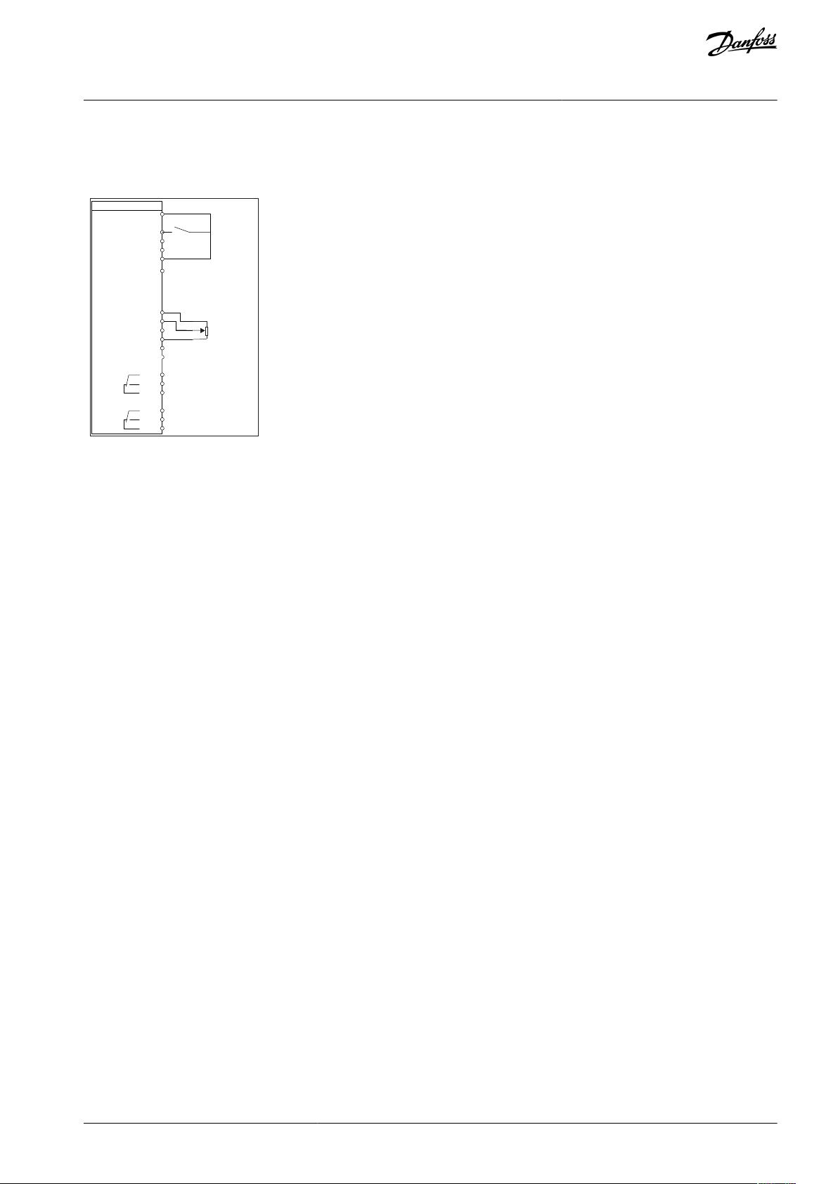
1.4 Electrical Wiring
AU363928304090en-000101 / 130R0982 | 5Danfoss A/S © 2021.07
L1
L2
L3
3-phase
power
input
PE
PE
+10 V DC
0-10 V DC-
0-10 V DC-
50 (+10 V OUT)
54 (A IN)
53 (A IN)
55 (COM A IN/OUT)
0/4-20 mA
0/4-20 mA
42 0/4-20 mA A OUT / D OUT
45 0/4-20 mA A OUT / D OUT
18 (D IN)
19 (D IN)
27 (D IN/OUT)
29 (D IN/OUT)
12 (+24 V OUT)
24 V (NPN)
20 (COM D IN)
O V (PNP)
24 V (NPN)
O V (PNP)
24 V (NPN)
O V (PNP)
24 V (NPN)
O V (PNP)
Bus ter.
Bus ter.
RS485
Interface
RS485
(N RS485) 69
(P RS485) 68
(Com RS485 ) 61
(PNP)-Source
(NPN)-Sink
ON=Terminated
OFF=Unterminated
ON
1 2
240 V AC 3 A
Not present on all power sizes
Do not connect shield to 61
01
02
03
relay 1
relay 2
UDC+
UDC-
Motor
U
V
W
e30bd467.12
06
05
04
240 V AC 3 A
VLT® Flow Drive FC 111
Programming Guide
Introduction
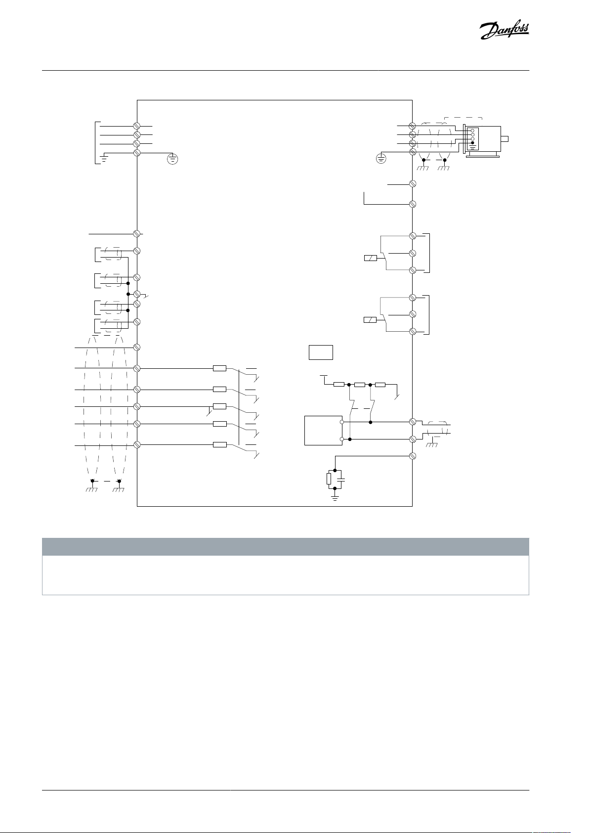
Illustration 1: Basic Wiring Schematic Drawing
There is no access to UDC- and UDC+ on the following units:
IP20, 380–480 V, 30–315 kW (40–450 hp)
-
N O T I C E
AU363928304090en-000101 / 130R09826 | Danfoss A/S © 2021.07
VLT® Flow Drive FC 111
Programming Guide
2 Safety
2.1 Safety Symbols
The following symbols are used in this manual:
D A N G E R
Indicates a hazardous situation which, if not avoided, will result in death or serious injury.
W A R N I N G
Indicates a hazardous situation which, if not avoided, could result in death or serious injury.
C A U T I O N
Indicates a hazardous situation which, if not avoided, could result in minor or moderate injury.
N O T I C E
Indicates information considered important, but not hazard-related (for example, messages relating to property damage).
Safety
2.2 Qualified Personnel
To allow trouble-free and safe operation of the unit, only qualified personnel with proven skills are allowed to transport, store, assemble, install, program, commission, maintain, and decommission this equipment.
Persons with proven skills:
•
Are qualified electrical engineers, or persons who have received training from qualified electrical engineers and are suitably
experienced to operate devices, systems, plant, and machinery in accordance with pertinent laws and regulations.
•
Are familiar with the basic regulations concerning health and safety/accident prevention.
•
Have read and understood the safety guidelines given in all manuals provided with the unit, especially the instructions given in
the Operating Guide.
•
Have good knowledge of the generic and specialist standards applicable to the specific application.
2.3 Safety Precautions
W A R N I N G
HAZARDOUS VOLTAGE
AC drives contain hazardous voltage when connected to the AC mains or connected on the DC terminals. Failure to perform
installation, start-up, and maintenance by skilled personnel can result in death or serious injury.
Only skilled personnel must perform installation, start-up, and maintenance.
-
W A R N I N G
UNINTENDED START
When the drive is connected to AC mains, DC supply, or load sharing, the motor may start at any time. Unintended start during
programming, service, or repair work can result in death, serious injury, or property damage. Start the motor with an external
switch, a fieldbus command, an input reference signal from the local control panel (LCP), via remote operation using MCT 10
software, or after a cleared fault condition.
Disconnect the drive from the mains.
-
Press [Off/Reset] on the LCP before programming parameters.
-
Ensure that the drive is fully wired and assembled when it is connected to AC mains, DC supply, or load sharing.
-
AU363928304090en-000101 / 130R0982 | 7Danfoss A/S © 2021.07
Voltage [V]
Power range [kW (hp)]
Minimum waiting time (minutes)
3x400
0.37–7.5 (0.5–10)
4
3x400
11–90 (15–125)
15
3x400
110–315 (150–450)
20
VLT® Flow Drive FC 111
Programming Guide
Safety
W A R N I N G
DISCHARGE TIME
The drive contains DC-link capacitors, which can remain charged even when the drive is not powered. High voltage can be
present even when the warning indicator lights are off.
Failure to wait the specified time after power has been removed before performing service or repair work could result in death or
serious injury.
Stop the motor.
-
Disconnect AC mains, permanent magnet type motors, and remote DC-link supplies, including battery back-ups, UPS, and
-
DC-link connections to other drives.
Wait for the capacitors to discharge fully. The minimum waiting time is specified in the table Discharge time and is also visible
-
on the nameplate on the top of the drive.
Before performing any service or repair work, use an appropriate voltage measuring device to make sure that the capacitors
-
are fully discharged.
Table 2: Discharge Time
W A R N I N G
LEAKAGE CURRENT HAZARD
Leakage currents exceed 3.5 mA. Failure to ground the drive properly can result in death or serious injury.
Ensure that the minimum size of the ground conductor complies with the local safety regulations for high touch current
-
equipment.
W A R N I N G
EQUIPMENT HAZARD
Contact with rotating shafts and electrical equipment can result in death or serious injury.
Ensure that only trained and qualified personnel perform installation, start-up, and maintenance.
-
Ensure that electrical work conforms to national and local electrical codes.
-
Follow the procedures in this manual.
-
C A U T I O N
INTERNAL FAILURE HAZARD
An internal failure in the drive can result in serious injury when the drive is not properly closed.
Ensure that all safety covers are in place and securely fastened before applying power.
-
AU363928304090en-000101 / 130R09828 | Danfoss A/S © 2021.07
e30bu792.11
B
a
c
k
Com.
4-10 Motor Speed Direction
[2] Both directions
Setup 1
A
B
1
12
13 14 15
11
11
10
9
8
7
6
5
4
3
2
C
D
Status
Main
Menu
Quick
Menu
Hand
On
OK
Menu
Off
Reset
Auto
On
Alarm
Warn.
On
11
B
C
D
A
13 14 15
12
11
11
5
4
10
6
7
8
9
1
2
11
LCP 32 LCP 31
4-10 Motor Speed Dir
ection
[2] Both directions
Status
Quick
Menu
Main
Menu
Menu
OK
Com.
On
Warn.
Alarm
Hand
On
Off
Reset
Auto
On
Back
1
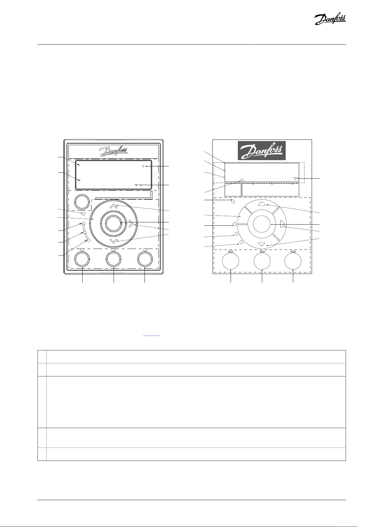
Parameter number and name.
2
Parameter value.
3
The setup number shows the active setup and the edit setup.
For LCP 32, the setup number only shows in Status menu, the number outside brackets is active setup, and the number inside
brackets is edit setup. For example, 1(2) means 1 is the active setup, and 2 is the edit setup.
For LCP 31, if the same setup acts as both active and edit setup, only that setup number is shown (factory setting). When the
active and the edit setup differ, both numbers are shown in the display (setup 12). The number flashing indicates the edit
setup.
4
Motor direction is shown to the bottom left of the display – indicated by a small arrow pointing either clockwise or counterclockwise.
5
The triangle indicates if the LCP is in Status, Quick Menu, or Main Menu.
VLT® Flow Drive FC 111
Programming Guide
3 Programming
3.1 Local Control Panel (LCP)
The LCP is divided into 4 functional sections.
•
A. Display
•
B. Menu key
•
C. Navigation keys and indicator lights
•
D. Operation keys and indicator lights
Programming
Illustration 2: Local Control Panel (LCP)
A. Display
The LCD-display of LCP 32 is illuminated with 3 alphanumeric lines, while the LCD-display of LCP 31 is illuminated with 2 alphanumeric lines. All data is shown on the LCP. The Table 3 describes the information that can be read from the display.
Table 3: Legend to Section A, Illustration 3
B. Menu key
Press [Menu] to select among Status, Quick Menu, or Main Menu.
C. Navigation keys and indicator lights
AU363928304090en-000101 / 130R0982 | 9Danfoss A/S © 2021.07

6
Com. (yellow indicator): Flashes during bus communication.
7
On (green indicator): Shows the power-on status.
8
Warn. (yellow indicator): Indicates a warning.
9
Alarm (red indicator): Indicates an alarm.
10
[Back]: For moving to the previous step or layer in the navigation structure.
11
Up arrow key, down arrow key, and right arrow key: For navigating among parameter groups and parameters, and within
parameters. They can also be used for setting local reference.
12
[OK]: For selecting a parameter and for accepting changes to parameter settings.
13
[Hand On]: Starts the motor and enables control of the drive via the LCP.
N O T I C E
[2] Coast inverse is the default option for parameter 5-12 Terminal 27 Digital Input. If there is no 24 V supply to terminal 27,
[Hand On] does not start the motor. Connect terminal 12 to terminal 27.
14
[Off/Reset]: Stops the compressor (Off). If in alarm mode, the alarm is reset.
15
[Auto On]: The drive is controlled either via control terminals or serial communication.
VLT® Flow Drive FC 111
Programming Guide
Table 4: Legend to Section C, Illustration 3
D. Operation keys and indicator lights
Table 5: Legend to Section D, Illustration 3
Programming
3.2 Menus
3.2.1 Status Menu
In the Status menu, the selection options are:
•
Motor frequency [Hz], parameter 16-13 Frequency.
•
Motor current [A], parameter 16-14 Motor current.
•
Motor speed reference in percentage [%], parameter 16-02 Reference [%].
•
Feedback, parameter 16-52 Feedback [Unit].
•
Motor power parameter 16-10 Power [kW] for kW, parameter 16-11 Power [hp] for hp. If parameter 0-03 Regional Settings is set to
[1] North America, motor power is shown in hp instead of kW.
•
Custom readout, parameter 16-09 Custom Readout.
•
Motor Speed [RPM], parameter 16-17 Speed [RPM].
3.2.2 Quick Menu
3.2.2.1 Quick Menu Introduction
Use the Quick Menu to program the most common functions. The Quick Menu consists of:
Wizard for open-loop applications.
•
Wizard for closed-loop applications.
•
Motor set-up.
•
Changes made.
•
AU363928304090en-000101 / 130R098210 | Danfoss A/S © 2021.07
FC
+24 V (OUT)
DIG IN
DIG IN
DIG IN
DIG IN
COM DIG IN
A OUT / D OUT
A OUT / D OUT
18
19
27
29
42
55
50
53
54
20
12
01
02
03
04
05
06
R2
R1
+
0–10 V
Start
+10 V (OUT)
A IN
A IN
COM IN/OUT
45
Reference
e30bb674.11
VLT® Flow Drive FC 111
Programming Guide
Programming
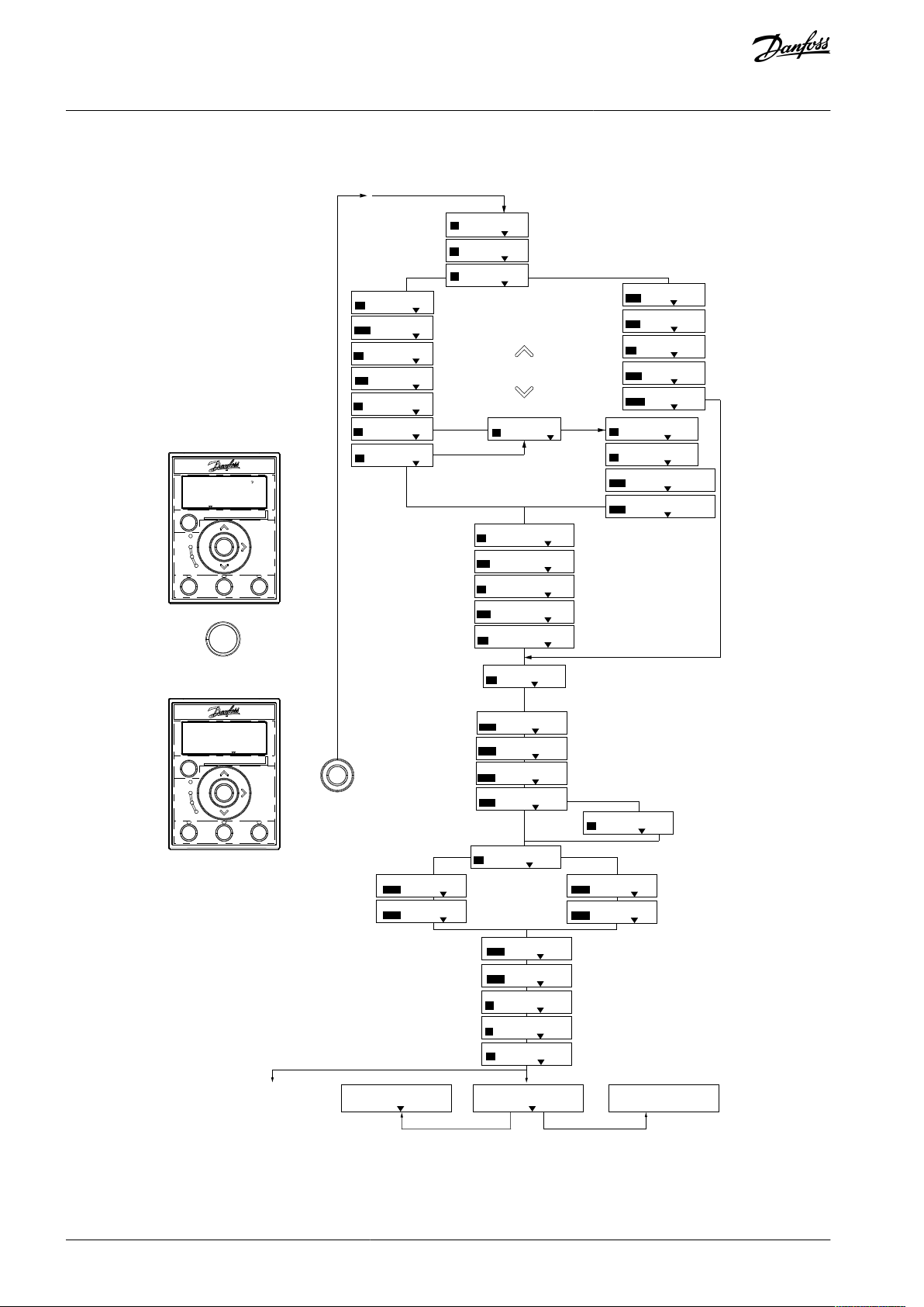
3.2.2.2 Setup Wizard Introduction
The built-in wizard menu guides the installer through the setup of the drive in a clear and structured manner for open-loop and
closed-loop applications, and for quick motor settings.
Illustration 3: Drive Wiring
The wizard can always be accessed again through the quick menu. Press [OK] to start the wizard. Press [Back] to return to the status
view.
AU363928304090en-000101 / 130R0982 | 11Danfoss A/S © 2021.07
Power kW/50 H z
Motor Power
Motor Voltage
Motor Frequency
Motor Current
Motor nominal speed
if
Select Regional Settings
... the Wizard starts
200-240V/50Hz/Delta
Grid Type
Induction motor
Asynchronous
Motor Type
Motor current
Motor nominal speed
Motor Cont. Rated Torque
Stator resistance
Motor poles
Back EMF at 1000 rpm
Motor type = IPM
Motor type = SPM
d-axis Inductance Sat. (LdSat)
[0]
[0]
3.8
A
3000
RPM
5.4
Nm
0.65
Ohms
8
Start Mode
Rotor Detection
[0]
Position Detection Gain
%
Off
100
Locked Rotor Detection
[0]
s
Locked Rotor Detection Time[s]
0.10
57
V
5
mH
q-axis Inductance (Lq)
5
mH
1.10
kW
400
V
50
Hz
Max Output Frequency
65
Hz
Motor Cable Length
50
m
4.66
A
1420
RPM
[0]
PM motor
Set Motor Speed low Limit
Hz
Set Motor Speed high Limit
Hz
Set Ramp 1 ramp-up time
s
Set Ramp 1 ramp-down Time
s
Active Flying start ?
Disable
Set T53 low Voltage
V
Set T53 high Voltage
V
Set T53 Low Current
A
Set T53 High Current
A
Voltage
AMA Failed
AMA Failed
Automatic Motor Adaption
Auto Motor Adapt OK
Press OK
Select Function of Relay 2
No function
Off
Select Function of Relay 1
[0] No function
Set Max Reference
Hz
Hz
Set Min Reference
AMA running
-----
Do AMA
(Do not AMA)
AMA OK
[0]
[0]
[0]
Select T53 Mode
Current
Current
Motor type = Induction
Motor type = PM motor
0000
0050
0010
0010
[0]
[0]
04.66
13.30
0050
0220
0000
0050
The next screen is
the Wizard screen.
Power-up Screen
e30bu808.12
q-axis Inductance Sat. (LqSat)
5
mH
Current at Min Inductance for d-axis
100
%
Current at Min Inductance for q-axis
100
%
d-axis Inductance (Lq)
5
mH
... the Wizard starts
Or
0-** FC-xxx Wizard
2-** Motor Setup
Status
Quick
Menu
Main
Menu
Menu
OK
Com.
On
Warn.
Alarm
Hand
On
Off
Reset
Auto
On
Back
1-** Closed Loop Set
0.0 Hz
Auto On
Status
Quick
Menu
Main
Menu
Menu
OK
Com.
On
Warn.
Alarm
Hand
On
Off
Reset
Auto
On
Back
0.000 kW
1 (1)
Menu
OK
VLT® Flow Drive FC 111
Programming Guide
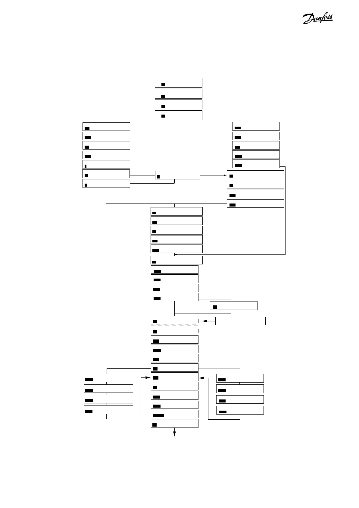
3.2.2.3 Setup Wizard for Open-loop Applications
Programming
Illustration 4: Setup Wizard for Open-loop Applications
AU363928304090en-000101 / 130R098212 | Danfoss A/S © 2021.07

•
•
•
•
•
•
•
•
•
•
•
•
•
•
•
•
•
•
•
•
•
•
•
•
•
•
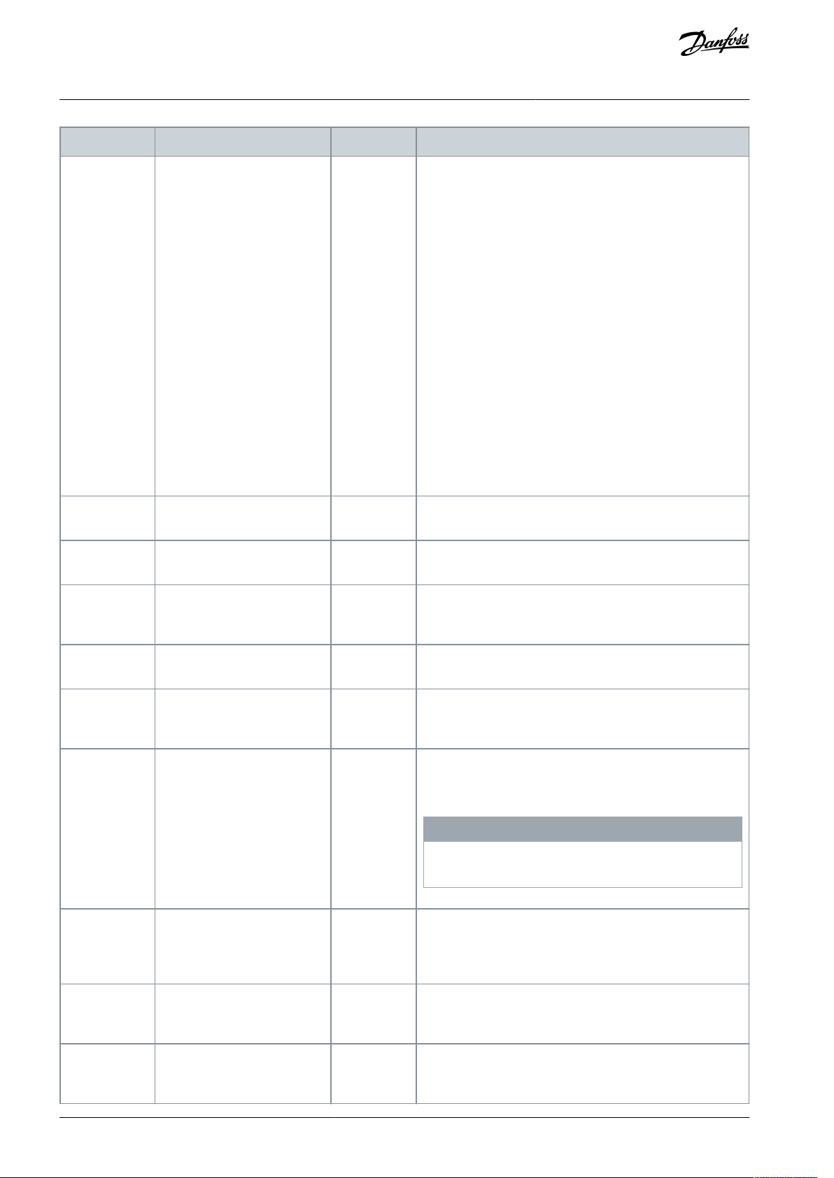
Parameter
Option
Default
Usage
Parameter 0-03
Regional Settings
[0] International
[1] US
[0] International
–
Parameter 0-06
GridType
[10] 380–440 V/50 Hz/IT-grid
[11] 380–440 V/50 Hz/Delta
[12] 380–440 V/50 Hz
[20] 440–480 V/50 Hz/IT-grid
[21] 440–480 V/50 Hz/Delta
[22] 440–480 V/50 Hz
[110] 380–440 V/60 Hz/IT-grid
[111] 380–440 V/60 Hz/Delta
[112] 380–440 V/60 Hz
[120] 440–480 V/60 Hz/IT-grid
[121] 440–480 V/60 Hz/Delta
[122] 440–480 V/60 Hz
Size related
Select the operating mode for restart after reconnection of
the drive to mains voltage after power down.
N O T I C E
Compared to 380–440 V groups, when selecting 440–
480 V groups, the rated current decreases accordingly.
Parameter 1-10
Motor Construction
*[0] Asynchron
[1] PM, non-salient SPM
[3] PM, salient IPM
[0] Asynchron
Setting the parameter value might change these parameters:
Parameter 1-01 Motor Control Principle.
Parameter 1-03 Torque Characteristics.
Parameter 1-08 Motor Control Bandwidth.
Parameter 1-14 Damping Gain.
Parameter 1-15 Low Speed Filter Time Const.
Parameter 1-16 High Speed Filter Time Const.
Parameter 1-17 Voltage Filter Time Const.
Parameter 1-20 Motor Power.
Parameter 1-22 Motor Voltage.
Parameter 1-23 Motor Frequency.
Parameter 1-24 Motor Current.
Parameter 1-25 Motor Nominal Speed.
Parameter 1-26 Motor Cont. Rated Torque.
Parameter 1-30 Stator Resistance (Rs).
Parameter 1-33 Stator Leakage Reactance (X1).
Parameter 1-35 Main Reactance (Xh).
Parameter 1-37 d-axis Inductance (Ld).
Parameter 1-38 q-axis Inductance (Lq).
Parameter 1-39 Motor Poles.
Parameter 1-40 Back EMF at 1000 RPM.
Parameter 1-44 d-axis Inductance Sat. (LdSat).
Parameter 1-45 q-axis Inductance Sat. (LqSat).
Parameter 1-46 Position Detection Gain.
Parameter 1-48 Current at Min Inductance for d-axis.
Parameter 1-49 Current at Min Inductance for q-axis.
Parameter 1-66 Min. Current at Low Speed.
VLT® Flow Drive FC 111
Programming Guide
Table 6: Setup Wizard for Open-loop Applications
Programming
AU363928304090en-000101 / 130R0982 | 13Danfoss A/S © 2021.07
•
•
•
•
•
•
•
•
•
•
•
•
•
•
•
Parameter
Option
Default
Usage
Parameter 1-70 PM Start Mode.
Parameter 1-72 Start Function.
Parameter 1-73 Flying Start.
Parameter 1-80 Function at Stop.
Parameter 1-82 Min Speed for Function at Stop [Hz].
Parameter 1-90 Motor Thermal Protection.
Parameter 2-00 DC Hold/Motor Preheat Current.
Parameter 2-01 DC Brake Current.
Parameter 2-02 DC Braking Time.
Parameter 2-04 DC Brake Cut In Speed.
Parameter 2-10 Brake Function.
Parameter 4-14 Motor Speed High Limit [Hz].
Parameter 4-19 Max Output Frequency.
Parameter 4-58 Missing Motor Phase Function.
Parameter 14-65 Speed Derate Dead Time Compensation.
Parameter 1-20
Motor Power
0.18–110 kW/0.25–150 hp
Size related
Enter the motor power from the nameplate data.
Parameter 1-22
Motor Voltage
50–1000 V
Size related
Enter the motor voltage from the nameplate data.
Parameter 1-23
Motor Frequency
20–400 Hz
Size related
Enter the motor frequency from the nameplate data.
Parameter 1-24
Motor Current
0.01–1000.00 A
Size related
Enter the motor current from the nameplate data.
Parameter 1-25
Motor Nominal
Speed
50–9999 RPM
Size related
Enter the motor nominal speed from the nameplate data.
Parameter 1-26
Motor Cont.
Rated Torque
0.1–1000.0 Nm
Size related
This parameter is available when parameter 1-10 Motor Con-
struction is set to options that enable permanent motor
mode.
N O T I C E
Changing this parameter affects the settings of other pa-
rameters.
Parameter 1-29
Automatic Motor Adaption
(AMA)
See parameter 1-29 Automatic
Motor Adaption (AMA).
Off
Performing an AMA optimizes motor performance.
Parameter 1-30
Stator Resistance (Rs)
0.000–99.990 Ω
Size related
Set the stator resistance value.
Parameter 1-37
d-axis Inductance (Ld)
0.000–1000.000 mH
Size related
Enter the value of the d-axis inductance. Obtain the value
from the permanent magnet motor datasheet.
VLT® Flow Drive FC 111
Programming Guide
Programming
AU363928304090en-000101 / 130R098214 | Danfoss A/S © 2021.07

Parameter
Option
Default
Usage
Parameter 1-38
q-axis Inductance (Lq)
0.000–1000.000 mH
Size related
Enter the value of the q-axis inductance.
Parameter 1-39
Motor Poles
2–100
4
Enter the number of motor poles.
Parameter 1-40
Back EMF at
1000 RPM
10–9000 V
Size related
Line-line RMS back EMF voltage at 1000 RPM.
Parameter 1-42
Motor Cable
Length
0–100 m
50 m
Enter the motor cable length.
Parameter 1-44
d-axis Inductance Sat.
(LdSat)
0.000–1000.000 mH
Size related
This parameter corresponds to the inductance saturation of
Ld. Ideally, this parameter has the same value as parameter
1-37 d-axis Inductance (Ld). However, if the motor supplier
provides an induction curve, enter the induction value,
which is 200% of the nominal current.
Parameter 1-45
q-axis Inductance Sat.
(LqSat)
0.000–1000.000 mH
Size related
This parameter corresponds to the inductance saturation of
Lq. Ideally, this parameter has the same value as parameter
1-38 q-axis Inductance (Lq). However, if the motor supplier
provides an induction curve, enter the induction value,
which is 200% of the nominal current.
Parameter 1-46
Position Detection Gain
20–200%
100%
Adjusts the height of the test pulse during position detection at start.
Parameter 1-48
Current at Min
Inductance for
d-axis
20–200%
100%
Enter the inductance saturation point.
Parameter 1-49
Current at Min
Inductance for
q-axis
20–200%
100%
This parameter specifies the saturation curve of the d- and qinductance values. From 20–100% of this parameter, the inductances are linearly approximated due to parameter 1-37
d-axis Inductance (Ld), parameter 1-38 q-axis Inductance (Lq),
parameter 1-44 d-axis Inductance Sat. (LdSat), and parameter
1-45 q-axis Inductance Sat. (LqSat).
Parameter 1-70
PM Start Mode
[0] Rotor Detection
[1] Parking
[3] Rotor Last Position
[1] Parking
Select the PM motor start mode.
Parameter 1-73
Flying Start
[0] Disabled
[1] Enabled
[0] Disabled
Select [1] Enabled to enable the drive to catch a motor spinning due to mains drop-out. Select [0] Disabled if this function is not required. When this parameter is set to [1] Ena-
bled, parameter 1-71 Start Delay and parameter 1-72 Start
Function are not functional. Parameter 1-73 Flying Start is ac-
tive in VVC+ mode only.
Parameter 3-02
Minimum Reference
-4999.000–4999.000
0
The minimum reference is the lowest value obtainable by
summing all references.
Parameter 3-03
Maximum Reference
-4999.000–4999.000
50
The maximum reference is the lowest obtainable by summing all references.
VLT® Flow Drive FC 111
Programming Guide
Programming
AU363928304090en-000101 / 130R0982 | 15Danfoss A/S © 2021.07

Parameter
Option
Default
Usage
Parameter 3-41
Ramp 1 Ramp
Up Time
0.01–3600.00 s
Size related
If induction motor is selected, the ramp-up time is from 0 to
rated parameter 1-23 Motor Frequency. If PM motor is selected, the ramp-up time is from 0 to parameter 1-25 Motor
Nominal Speed.
Parameter 3-42
Ramp 1 Ramp
Down Time
0.01–3600.00 s
Size related
For induction motors, the ramp-down time is from rated pa-
rameter 1-23 Motor Frequency to 0. For PM motors, the rampdown time is from parameter 1-25 Motor Nominal Speed to 0.
Parameter 4-12
Motor Speed
Low Limit [Hz]
0.0–400.0 Hz
0 Hz
Enter the minimum limit for low speed.
Parameter 4-14
Motor Speed
High Limit [Hz]
0.0–400.0 Hz
100 Hz
Enter the maximum limit for high speed.
Parameter 4-19
Max Output
Frequency
0.0–400.0 Hz
100 Hz
Enter the maximum output frequency value. If parameter
4-19 Max Output Frequency is set lower than parameter 4-14
Motor Speed High Limit [Hz], parameter 4-14 Motor Speed High
Limit [Hz] is set equal to parameter 4-19 Max Output Frequency automatically.
Parameter 5-40
Function Relay
See parameter 5-40 Function
Relay.
[9] Alarm
Select the function to control output relay 1.
Parameter 5-40
Function Relay
See parameter 5-40 Function
Relay.
[5] Drive running
Select the function to control output relay 2.
Parameter 6-10
Terminal 53
Low Voltage
0.00–10.00 V
0.07 V
Enter the voltage that corresponds to the low reference value.
Parameter 6-11
Terminal 53
High Voltage
0.00–10.00 V
10 V
Enter the voltage that corresponds to the high reference value.
Parameter 6-12
Terminal 53
Low Current
0.00–20.00 mA
4 mA
Enter the current that corresponds to the low reference value.
Parameter 6-13
Terminal 53
High Current
0.00–20.00 mA
20 mA
Enter the current that corresponds to the high reference value.
Parameter 6-19
Terminal 53
mode
[0] Current
[1] Voltage
[1] Voltage
Select if terminal 53 is used for current or voltage input.
Parameter
30-22 Locked
Rotor Detection
[0] Off
[1] On
[0] Off
–
Parameter
30-23 Locked
Rotor Detection
Time [s]
0.05–1 s
0.10 s
–
VLT® Flow Drive FC 111
Programming Guide
Programming
AU363928304090en-000101 / 130R098216 | Danfoss A/S © 2021.07
6-29 Terminal 54 Mode
[1]
Voltage
6-25 T54 high Feedback
0050
Hz
20-94 PI integral time
0020.00
s
Current
Voltage
This dialog is forced to be set to
[1] Analog input 54
20-00 Feedback 1 source
[1]
Analog input 54
3-10 Preset reference [0]
0.00
3-03 Max Reference
50.00
3-02 Min Reference
0.00
Induction motor
1-73 Flying Start
[0]
No
1-22 Motor Voltage
400
V
1-24 Motor Current
04.66
A
1-25 Motor nominal speed
1420
RPM
3-41 Ramp 1 ramp-up time
0010
s
3-42 Ramp1 ramp-down time
0010
s
0-06 Grid Type
4-12 Motor speed low limit
0016
Hz
4-14 Motor speed high limit
0050
Hz
e30bc402.16
1-20 Motor Power
1.10
kW
1-23 Motor Frequency
50
Hz
6-22 T54 Low Current
A
6-24 T54 low Feedback
0016
Hz
6-23 T54 high Current
13.30
A
6-25 T54 high Feedback
0050
0.01
s
20-81 PI Normal/Inverse Control
[0]
Normal
20-83 PI Normal/Inverse Control
0050
Hz
20-93 PI Proportional Gain
00.50
1-29 Automatic Motor Adaption
[0]
Off
6-20 T54 low Voltage
0050
V
6-24 T54 low Feedback
0016
Hz
6-21 T54 high Voltage
0220
V
6-26
T54 Filter time const.
1-00 Configuration Mode
[3]
Closed Loop
0-03 Regional Settings
[0]
Power kW/50 Hz
3-16 Reference Source 2
[0]
No Operation
1-10 Motor Type
[0]
Asynchronous
[0]
200-240V/50Hz/Delta
1-30 Stator Resistance
0.65
Ohms
1-25 Motor Nominal Speed
3000
RPM
1-24 Motor Current
3.8
A
1-26 Motor Cont. Rated Torque
5.4
Nm
1-38 q-axis inductance(Lq)
5
mH
4-19 Max Ouput Frequency
0065
Hz
1-40 Back EMF at 1000 RPM
57
V
PM motor
1-39 Motor Poles
8
%
04.66
Hz
Motor type = Induction
Motor type = PM motor
Motor type = IPM
Motor type = SPM
1-44 d-axis Inductance Sat. (LdSat)
(1-70) Start Mode
Rotor Detection
[0]
1-46 Position Detection Gain
%
Off
100
30-22 Locked Rotor Detection
[0]
s
30-23 Locked Rotor Detection Time[s]
0.10
5
mH
1-42 Motor Cable Length
50
m
(1-45) q-axis Inductance Sat. (LqSat)
5
mH
(1-48) Current at Min Inductanc e for d-axis
100
%
1-49 Current at Min Inductanc e for q-axis
100
%
1-37 d-axis inductance(Lq)
5
mH
... the Wizard starts
... the Wizard starts
VLT® Flow Drive FC 111
Programming Guide
3.2.2.4 Setup Wizard for Closed-loop Applications
Programming
Illustration 5: Setup Wizard for Closed-loop Applications
AU363928304090en-000101 / 130R0982 | 17Danfoss A/S © 2021.07

•
•
•
•
•
•
•
•
•
•
•
•
•
•
•
•
•
•
•
•
•
•
•
•
Parameter
Range
Default
Usage
Parameter 0-03
Regional Settings
[0] International
[1] US
[0] International
–
Parameter 0-06
GridType
[10] 380–440 V/50 Hz/IT-grid
[11] 380–440 V/50 Hz/Delta
[12] 380–440 V/50 Hz
[20] 440–480 V/50 Hz/IT-grid
[21] 440–480 V/50 Hz/Delta
[22] 440–480 V/50 Hz
[110] 380–440 V/60 Hz/IT-grid
[111] 380–440 V/60 Hz/Delta
[112] 380–440 V/60 Hz
[120] 440–480 V/60 Hz/IT-grid
[121] 440–480 V/60 Hz/Delta
[122] 440–480 V/60 Hz
Size selected
Select the operating mode for restart after reconnection of
the drive to mains voltage after power down.
Parameter 1-00
Configuration
Mode
[0] Open loop
[3] Closed loop
[0] Open loop
Select [3] Closed loop.
Parameter 1-10
Motor Construction
*[0] Asynchron
[1] PM, non-salient SPM
[3] PM, salient IPM
[0] Asynchron
Setting the parameter value might change these parameters:
Parameter 1-01 Motor Control Principle.
Parameter 1-03 Torque Characteristics.
Parameter 1-08 Motor Control Bandwidth.
Parameter 1-14 Damping Gain.
Parameter 1-15 Low Speed Filter Time Const.
Parameter 1-16 High Speed Filter Time Const.
Parameter 1-17 Voltage Filter Time Const.
Parameter 1-20 Motor Power.
Parameter 1-22 Motor Voltage.
Parameter 1-23 Motor Frequency.
Parameter 1-24 Motor Current.
Parameter 1-25 Motor Nominal Speed.
Parameter 1-26 Motor Cont. Rated Torque.
Parameter 1-30 Stator Resistance (Rs).
Parameter 1-33 Stator Leakage Reactance (X1).
Parameter 1-35 Main Reactance (Xh).
Parameter 1-37 d-axis Inductance (Ld).
Parameter 1-38 q-axis Inductance (Lq).
Parameter 1-39 Motor Poles.
Parameter 1-40 Back EMF at 1000 RPM.
Parameter 1-44 d-axis Inductance Sat. (LdSat).
Parameter 1-45 q-axis Inductance Sat. (LqSat).
Parameter 1-46 Position Detection Gain.
Parameter 1-48 Current at Min Inductance for d-axis.
VLT® Flow Drive FC 111
Programming Guide
Table 7: Setup Wizard for Closed-loop Applications
Programming
AU363928304090en-000101 / 130R098218 | Danfoss A/S © 2021.07

•
•
•
•
•
•
•
•
•
•
•
•
•
•
•
•
•
Parameter
Range
Default
Usage
Parameter 1-49 Current at Min Inductance for q-axis.
Parameter 1-66 Min. Current at Low Speed.
Parameter 1-70 PM Start Mode.
Parameter 1-72 Start Function.
Parameter 1-73 Flying Start.
Parameter 1-80 Function at Stop.
Parameter 1-82 Min Speed for Function at Stop [Hz].
Parameter 1-90 Motor Thermal Protection.
Parameter 2-00 DC Hold/Motor Preheat Current.
Parameter 2-01 DC Brake Current.
Parameter 2-02 DC Braking Time.
Parameter 2-04 DC Brake Cut In Speed.
Parameter 2-10 Brake Function.
Parameter 4-14 Motor Speed High Limit [Hz].
Parameter 4-19 Max Output Frequency.
Parameter 4-58 Missing Motor Phase Function.
Parameter 14-65 Speed Derate Dead Time Compensation.
Parameter 1-20
Motor Power
0.18–110 kW/0.25–150 hp
Size related
Enter the motor power from the nameplate data.
Parameter 1-22
Motor Voltage
50–1000 V
Size related
Enter the motor voltage from the nameplate data.
Parameter 1-23
Motor Frequency
20–400 Hz
Size related
Enter the motor frequency from the nameplate data.
Parameter 1-24
Motor Current
0.01–1000.00 A
Size related
Enter the motor current from the nameplate data.
Parameter 1-25
Motor Nominal
Speed
50–60000 RPM
Size related
Enter the motor nominal speed from the nameplate data.
Parameter 1-26
Motor Cont.
Rated Torque
0.1–10000.0 Nm
Size related
This parameter is available when parameter 1-10 Motor Con-
struction is set to options that enable permanent motor
mode.
N O T I C E
Changing this parameter affects the settings of other pa-
rameters.
Parameter 1-29
Automatic Motor Adaption
(AMA)
–
Off
Performing an AMA optimizes motor performance.
Parameter 1-30
Stator Resistance (Rs)
0.000–9999.000 Ω
Size related
Set the stator resistance value.
VLT® Flow Drive FC 111
Programming Guide
Programming
AU363928304090en-000101 / 130R0982 | 19Danfoss A/S © 2021.07

Parameter
Range
Default
Usage
Parameter 1-37
d-axis Inductance (Ld)
0.000–1000.000 mH
Size related
Enter the value of the d-axis inductance. Obtain the value
from the permanent magnet motor datasheet.
Parameter 1-38
q-axis Inductance (Lq)
0.000–1000.000 mH
Size related
Enter the value of the q-axis inductance.
Parameter 1-39
Motor Poles
2–100
4
Enter the number of motor poles.
Parameter 1-40
Back EMF at
1000 RPM
10–9000 V
Size related
Line-line RMS back EMF voltage at 1000 RPM.
Parameter 1-42
Motor Cable
Length
0–100 m
50 m
Enter the motor cable length.
Parameter 1-44
d-axis Inductance Sat.
(LdSat)
0.000–1000.000 mH
Size related
This parameter corresponds to the inductance saturation of
Ld. Ideally, this parameter has the same value as parameter
1-37 d-axis Inductance (Ld). However, if the motor supplier
provides an induction curve, enter the induction value,
which is 200% of the nominal current.
Parameter 1-45
q-axis Inductance Sat.
(LqSat)
0.000–1000.000 mH
Size related
This parameter corresponds to the inductance saturation of
Lq. Ideally, this parameter has the same value as parameter
1-38 q-axis Inductance (Lq). However, if the motor supplier
provides an induction curve, enter the induction value,
which is 200% of the nominal current.
Parameter 1-46
Position Detection Gain
20–200%
100%
Adjusts the height of the test pulse during position detection at start.
Parameter 1-48
Current at Min
Inductance for
d-axis
20–200%
100%
Enter the inductance saturation point.
Parameter 1-49
Current at Min
Inductance for
q-axis
20–200%
100%
This parameter specifies the saturation curve of the d- and qinductance values. From 20–100% of this parameter, the inductances are linearly approximated due to parameter 1-37
d-axis Inductance (Ld), parameter 1-38 q-axis Inductance (Lq),
parameter 1-44 d-axis Inductance Sat. (LdSat), and parameter
1-45 q-axis Inductance Sat. (LqSat).
Parameter 1-70
PM Start Mode
[0] Rotor Detection
[1] Parking
[3] Rotor Last Position
[1] Parking
Select the PM motor start mode.
Parameter 1-73
Flying Start
[0] Disabled
[1] Enabled
[0] Disabled
Select [1] Enabled to enable the drive to catch a spinning motor in, for example, fan applications. When PM is selected,
this parameter is enabled.
Parameter 3-02
Minimum Reference
-4999.000–4999.000
0
The minimum reference is the lowest value obtainable by
summing all references.
VLT® Flow Drive FC 111
Programming Guide
Programming
AU363928304090en-000101 / 130R098220 | Danfoss A/S © 2021.07

Parameter
Range
Default
Usage
Parameter 3-03
Maximum Reference
-4999.000–4999.000
50
The maximum reference is the highest value obtainable by
summing all references.
Parameter 3-10
Preset Reference
-100–100%
0
Enter the setpoint.
Parameter 3-41
Ramp 1 Ramp
Up Time
0.05–3600.0 s
Size related
Ramp-up time from 0 to rated parameter 1-23 Motor Frequen-
cy for induction motors. Ramp-up time from 0 to parameter
1-25 Motor Nominal Speed for PM motors.
Parameter 3-42
Ramp 1 Ramp
Down Time
0.05–3600.0 s
Size related
Ramp-down time from rated parameter 1-23 Motor Frequency
to 0 for induction motors. Ramp-down time from parameter
1-25 Motor Nominal Speed to 0 for PM motors.
Parameter 4-12
Motor Speed
Low Limit [Hz]
0.0–400.0 Hz
0.0 Hz
Enter the minimum limit for low speed.
Parameter 4-14
Motor Speed
High Limit [Hz]
0.0–400.0 Hz
100 Hz
Enter the minimum limit for high speed.
Parameter 4-19
Max Output
Frequency
0.0–400.0 Hz
100 Hz
Enter the maximum output frequency value. If parameter
4-19 Max Output Frequency is set lower than parameter 4-14
Motor Speed High Limit [Hz], parameter 4-14 Motor Speed High
Limit [Hz] is set equal to parameter 4-19 Max Output Frequency automatically.
Parameter 6-20
Terminal 54
Low Voltage
0.00–10.00 V
0.07 V
Enter the voltage that corresponds to the low reference value.
Parameter 6-21
Terminal 54
High Voltage
0.00–10.00 V
10.00 V
Enter the voltage that corresponds to the high reference value.
Parameter 6-22
Terminal 54
Low Current
0.00–20.00 mA
4.00 mA
Enter the current that corresponds to the low reference value.
Parameter 6-23
Terminal 54
High Current
0.00–20.00 mA
20.00 mA
Enter the current that corresponds to the high reference value.
Parameter 6-24
Terminal 54
Low Ref./Feedb.
Value
-4999–4999
0
Enter the feedback value that corresponds to the voltage or
current set in parameter 6-20 Terminal 54 Low Voltage/param-
eter 6-22 Terminal 54 Low Current.
Parameter 6-25
Terminal 54
High Ref./
Feedb. Value
-4999–4999
50
Enter the feedback value that corresponds to the voltage or
current set in parameter 6-21 Terminal 54 High Voltage/pa-
rameter 6-23 Terminal 54 High Current.
Parameter 6-26
Terminal 54 Filter Time Constant
0.00–10.00 s
0.01
Enter the filter time constant.
VLT® Flow Drive FC 111
Programming Guide
Programming
AU363928304090en-000101 / 130R0982 | 21Danfoss A/S © 2021.07

Parameter
Range
Default
Usage
Parameter 6-29
Terminal 54
mode
[0] Current
[1] Voltage
[1] Voltage
Select if terminal 54 is used for current or voltage input.
Parameter
20-81 PI Normal/Inverse
Control
[0] Normal
[1] Inverse
[0] Normal
Select [0] Normal to set the process control to increase the
output speed when the process error is positive. Select [1] In-
verse to reduce the output speed.
Parameter
20-83 PI Start
Speed [Hz]
0–200 Hz
0 Hz
Enter the motor speed to be attained as a start signal for
commencement of PI control.
Parameter
20-93 PI Proportional Gain
0.00–10.00
0.01
Enter the process controller proportional gain. Quick control
is obtained at high amplification. However, if amplification is
too high, the process may become unstable.
Parameter
20-94 PI Integral Time
0.1–999.0 s
999.0 s
Enter the process controller integral time. Obtain quick control through a short integral time, though if the integral time
is too short, the process becomes unstable. An excessively
long integral time disables the integral action.
Parameter
30-22 Locked
Rotor Detection
[0] Off
[1] On
[0] Off
–
Parameter
30-23 Locked
Rotor Detection
Time [s]
0.05–1.00 s
0.10 s
–
Parameter
Range
Default
Usage
Parameter 0-03
Regional Settings
[0] International
[1] US
[0] International
–
Parameter 0-06
GridType
[10] 380–440 V/50 Hz/IT-grid
[11] 380–440 V/50 Hz/Delta
[12] 380–440 V/50 Hz
[20] 440–480 V/50 Hz/IT-grid
[21] 440–480 V/50 Hz/Delta
[22] 440–480 V/50 Hz
[110] 380–440 V/60 Hz/IT-grid
[111] 380–440 V/60 Hz/Delta
[112] 380–440 V/60 Hz
[120] 440–480 V/60 Hz/IT-grid
[121] 440–480 V/60 Hz/Delta
[122] 440–480 V/60 Hz
Size selected
Select the operating mode for restart after reconnection of
the drive to mains voltage after power down.
Parameter 1-10
Motor Construction
*[0] Asynchron
[1] PM, non-salient SPM
[3] PM, salient IPM
[0] Asynchron
Setting the parameter value might change these parameters:
VLT® Flow Drive FC 111
Programming Guide
Programming
3.2.2.5 Motor Setup
The motor setup wizard guides users through the needed motor parameters.
Table 8: Motor Setup Wizard Settings
AU363928304090en-000101 / 130R098222 | Danfoss A/S © 2021.07

•
•
•
•
•
•
•
•
•
•
•
•
•
•
•
•
•
•
•
•
•
•
•
•
•
•
•
•
•
•
•
•
•
•
•
•
•
•
•
•
•
Parameter
Range
Default
Usage
Parameter 1-01 Motor Control Principle.
Parameter 1-03 Torque Characteristics.
Parameter 1-08 Motor Control Bandwidth.
Parameter 1-14 Damping Gain.
Parameter 1-15 Low Speed Filter Time Const.
Parameter 1-16 High Speed Filter Time Const.
Parameter 1-17 Voltage Filter Time Const.
Parameter 1-20 Motor Power.
Parameter 1-22 Motor Voltage.
Parameter 1-23 Motor Frequency.
Parameter 1-24 Motor Current.
Parameter 1-25 Motor Nominal Speed.
Parameter 1-26 Motor Cont. Rated Torque.
Parameter 1-30 Stator Resistance (Rs).
Parameter 1-33 Stator Leakage Reactance (X1).
Parameter 1-35 Main Reactance (Xh).
Parameter 1-37 d-axis Inductance (Ld).
Parameter 1-38 q-axis Inductance (Lq).
Parameter 1-39 Motor Poles.
Parameter 1-40 Back EMF at 1000 RPM.
Parameter 1-44 d-axis Inductance Sat. (LdSat).
Parameter 1-45 q-axis Inductance Sat. (LqSat).
Parameter 1-46 Position Detection Gain.
Parameter 1-48 Current at Min Inductance for d-axis.
Parameter 1-49 Current at Min Inductance for q-axis.
Parameter 1-66 Min. Current at Low Speed.
Parameter 1-70 PM Start Mode.
Parameter 1-72 Start Function.
Parameter 1-73 Flying Start.
Parameter 1-80 Function at Stop.
Parameter 1-82 Min Speed for Function at Stop [Hz].
Parameter 1-90 Motor Thermal Protection.
Parameter 2-00 DC Hold/Motor Preheat Current.
Parameter 2-01 DC Brake Current.
Parameter 2-02 DC Braking Time.
Parameter 2-04 DC Brake Cut In Speed.
Parameter 2-10 Brake Function.
Parameter 4-14 Motor Speed High Limit [Hz].
Parameter 4-19 Max Output Frequency.
Parameter 4-58 Missing Motor Phase Function.
Parameter 14-65 Speed Derate Dead Time Compensation.
VLT® Flow Drive FC 111
Programming Guide
Programming
AU363928304090en-000101 / 130R0982 | 23Danfoss A/S © 2021.07

Parameter
Range
Default
Usage
Parameter 1-20
Motor Power
0.18–110 kW/0.25–150 hp
Size related
Enter the motor power from the nameplate data.
Parameter 1-22
Motor Voltage
50–1000 V
Size related
Enter the motor voltage from the nameplate data.
Parameter 1-23
Motor Frequency
20–400 Hz
Size related
Enter the motor frequency from the nameplate data.
Parameter 1-24
Motor Current
0.01–10000.00 A
Size related
Enter the motor current from the nameplate data.
Parameter 1-25
Motor Nominal
Speed
50–9999 RPM
Size related
Enter the motor nominal speed from the nameplate data.
Parameter 1-26
Motor Cont.
Rated Torque
0.1–1000.0 Nm
Size related
This parameter is available when parameter 1-10 Motor Con-
struction is set to options that enable permanent motor
mode.
N O T I C E
Changing this parameter affects the settings of other pa-
rameters.
Parameter 1-30
Stator Resistance (Rs)
0–99.990 Ω
Size related
Set the stator resistance value.
Parameter 1-37
d-axis Inductance (Ld)
0.000–1000.000 mH
Size related
Enter the value of the d-axis inductance. Obtain the value
from the permanent magnet motor datasheet.
Parameter 1-38
q-axis Inductance (Lq)
0.000–1000.000 mH
Size related
Enter the value of the q-axis inductance.
Parameter 1-39
Motor Poles
2–100
4
Enter the number of motor poles.
Parameter 1-40
Back EMF at
1000 RPM
10–9000 V
Size related
Line-line RMS back EMF voltage at 1000 RPM.
Parameter 1-42
Motor Cable
Length
0–100 m
50 m
Enter the motor cable length.
Parameter 1-44
d-axis Inductance Sat.
(LdSat)
0.000–1000.000 mH
Size related
This parameter corresponds to the inductance saturation of
Ld. Ideally, this parameter has the same value as parameter
1-37 d-axis Inductance (Ld). However, if the motor supplier
provides an induction curve, enter the induction value,
which is 200% of the nominal current.
Parameter 1-45
q-axis Inductance Sat.
(LqSat)
0.000–1000.000 mH
Size related
This parameter corresponds to the inductance saturation of
Lq. Ideally, this parameter has the same value as parameter
1-38 q-axis Inductance (Lq). However, if the motor supplier
provides an induction curve, enter the induction value,
which is 200% of the nominal current.
VLT® Flow Drive FC 111
Programming Guide
Programming
AU363928304090en-000101 / 130R098224 | Danfoss A/S © 2021.07

Parameter
Range
Default
Usage
Parameter 1-46
Position Detection Gain
20–200%
100%
Adjusts the height of the test pulse during position detection at start.
Parameter 1-48
Current at Min
Inductance for
d-axis
20–200%
100%
Enter the inductance saturation point.
Parameter 1-49
Current at Min
Inductance for
q-axis
20–200%
100%
This parameter specifies the saturation curve of the d- and qinductance values. From 20–100% of this parameter, the inductances are linearly approximated due to parameter 1-37
d-axis Inductance (Ld), parameter 1-38 q-axis Inductance (Lq),
parameter 1-44 d-axis Inductance Sat. (LdSat), and parameter
1-45 q-axis Inductance Sat. (LqSat).
Parameter 1-70
PM Start Mode
[0] Rotor Detection
[1] Parking
[3] Rotor Last Position
[1] Parking
Select the PM motor start mode.
Parameter 1-73
Flying Start
[0] Disabled
[1] Enabled
[0] Disabled
Select [1] Enabled to enable the drive to catch a spinning motor.
Parameter 3-41
Ramp 1 Ramp
Up Time
0.05–3600.0 s
Size related
Ramp-up time from 0 to rated parameter 1-23 Motor Frequen-
cy.
Parameter 3-42
Ramp 1 Ramp
Down Time
0.05–3600.0 s
Size related
Ramp-down time from rated parameter 1-23 Motor Frequency
to 0.
Parameter 4-12
Motor Speed
Low Limit [Hz]
0.0–400.0 Hz
0.0 Hz
Enter the minimum limit for low speed.
Parameter 4-14
Motor Speed
High Limit [Hz]
0.0–400.0 Hz
100.0 Hz
Enter the maximum limit for high speed.
Parameter 4-19
Max Output
Frequency
0.0–400.0 Hz
100.0 Hz
Enter the maximum output frequency value. If parameter
4-19 Max Output Frequency is set lower than parameter 4-14
Motor Speed High Limit [Hz], parameter 4-14 Motor Speed High
Limit [Hz] is set equal to parameter 4-19 Max Output Frequency automatically.
Parameter
30-22 Locked
Rotor Detection
[0] Off
[1] On
[0] Off
–
Parameter
30-23 Locked
Rotor Detection
Time [s]
0.05–1.00 s
0.10 s
–
VLT® Flow Drive FC 111
Programming Guide
Programming
AU363928304090en-000101 / 130R0982 | 25Danfoss A/S © 2021.07

VLT® Flow Drive FC 111
Programming Guide
3.2.2.6 Changes Made Function
The changes made function lists all parameters changed from default settings.
•
The list shows only parameters that have been changed in the current edit setup.
•
Parameters that have been reset to default values are not listed.
•
The message Empty indicates that no parameters have been changed.
3.2.2.7 Changing Parameter Settings
Procedure
1.
To enter the Quick Menu, press the [Menu] key until the indicator in the display is placed above Quick Menu.
2.
Press [▵] [▿] to select the wizard, closed-loop setup, motor setup, or changes made.
3.
Press [OK].
4.
Press [▵] [▿] to browse through the parameters in the Quick Menu.
5.
Press [OK] to select a parameter.
6.
Press [▵] [▿] to change the value of a parameter setting.
7.
Press [OK] to accept the change.
8.
Press either [Back] twice to enter Status, or press [Menu] once to enter the Main Menu.
3.2.2.8 Accessing All Parameters via the Main Menu
Procedure
1.
Press the [Menu] key until the indicator in the display is placed above Main Menu.
2.
Press [▵] [▿] to browse through the parameter groups.
3.
Press [OK] to select a parameter group.
4.
Press [▵] [▿] to browse through the parameters in the specific group.
5.
Press [OK] to select the parameter.
6.
Press [▵] [▿] to set/change the parameter value.
7.
Press [OK] to accept the change.
Programming
3.2.3 Main Menu
Press [Menu] to access the main menu and program all parameters. The main menu parameters can be accessed readily unless a
password has been created via parameter 0-60 Main Menu Password.
For most applications, it is not necessary to access the main menu parameters. The quick menu provides the simplest and quickest
access to the typical required parameters.
3.3 Quick Transfer of Parameter Settings between Multiple Drives
When the set-up of a drive is completed, store the data in the LCP. Then connect the LCP to another drive and copy the parameter
settings to the new drive.
3.3.1 Transferring Data from the Drive to the LCP
Procedure
1.
Go to parameter 0-50 LCP Copy.
Press [OK].
2.
3.
Select [1] All to LCP.
Press [OK].
4.
3.3.2 Transferring Data from the LCP to the Drive
Procedure
1.
Go to parameter 0-50 LCP Copy.
Press [OK].
2.
3.
Select [2] All from LCP.
Press [OK].
4.
3.4 Readout and Programming of Indexed Parameters
Procedure
AU363928304090en-000101 / 130R098226 | Danfoss A/S © 2021.07

VLT® Flow Drive FC 111
Programming Guide
1.
Select the parameter and press [OK].
2.
Press [▵]/[▿] to scroll through the indexed values.
3.
To change the parameter value, select the indexed value and press [OK].
4.
Change the value by pressing [▵]/[▿].
5.
Press [OK] or [Cancel] to accept or abort the new setting.
6.
Press [Back] to leave the parameter.
3.5 Initialization to Default Settings
There are 2 ways to initialize the drive to the default settings.
•
Recommended initialization
•
Two-finger initialization
Initialization of parameters is confirmed by alarm 80, Drive initialised in the display after the power cycle.
3.5.1 Recommended Initialization
Procedure
1.
Select parameter 14-22 Operation Mode.
Press [OK].
2.
3.
Select [2] Initialisation and press [OK].
Power off the drive and wait until the display turns off.
4.
Reconnect the mains supply. The drive is now reset, except for the following parameters.
5.
Programming
•
Parameter 1-06 Clockwise Direction
•
Parameter 8-30 Protocol
•
Parameter 8-31 Address
•
Parameter 8-32 Baud Rate
•
Parameter 8-33 Parity / Stop Bits
•
Parameter 8-35 Minimum Response Delay
•
Parameter 8-36 Maximum Response Delay
•
Parameter 8-37 Maximum Inter-char delay
•
Parameter 8-70 BACnet Device Instance
•
Parameter 8-72 MS/TP Max Masters
•
Parameter 8-73 MS/TP Max Info Frames
•
Parameter 8-74 "I am" Service
•
Parameter 8-75 Intialisation Password
•
Parameter 15-00 Operating hours to parameter 15-05 Over Volt's
•
Parameter 15-03 Power Up's
•
Parameter 15-04 Over Temp's
•
Parameter 15-05 Over Volt's
•
Parameter 15-30 Alarm Log: Error Code
•
Parameter group 15-4* Drive identification
•
Parameter 18-10 FireMode Log:Event
3.5.2 Two-finger Initialization
Procedure
Power off the drive.
1.
Press [OK] and [Menu].
2.
Power up the drive while still pressing the keys for 10 s.
3.
AU363928304090en-000101 / 130R0982 | 27Danfoss A/S © 2021.07

VLT® Flow Drive FC 111
Programming Guide
4.
The drive is now reset, except for the following parameters.
•
Parameter 1-06 Clockwise Direction
•
Parameter 15-00 Operating hours
•
Parameter 15-03 Power Up's
•
Parameter 15-04 Over Temp's
•
Parameter 15-05 Over Volt's
•
Parameter group 15-4* Drive identification
•
Parameter 18-10 FireMode Log:Event
Programming
AU363928304090en-000101 / 130R098228 | Danfoss A/S © 2021.07

0-** Operation/Display
0-0* Basic Settings
0-01 Language
0-03 Regional Settings
0-04 Operating State at Pow-
er-up
0-06 GridType
0-07 Auto DC Braking
0-1* Set-up Operations
0-10 Active Set-up
0-11 Programming Set-up
0-12 Link Setups
0-16 Application Selection
0-3* LCP Custom Readout
0-30 Custom Readout Unit
0-31 Custom Readout Min
Value
0-32 Custom Readout Max
Value
0-37 Display Text 1
0-38 Display Text 2
0-39 Display Text 3
0-4* LCP Keypad
0-40 [Hand on] Key on LCP
0-42 [Auto on] Key on LCP
0-44 [Off/Reset] Key on LCP
0-5* Copy/Save
0-50 LCP Copy
0-51 Set-up Copy
0-6* Password
0-60 Main Menu Password
0-61 Access to Main Menu
w/o Password
1-** Load and Motor
1-0* General Settings
1-00 Configuration Mode
1-01 Motor Control Principle
1-03 Torque Characteristics
1-06 Clockwise Direction
1-08 Motor Control Band-
width
1-1* Motor Selection
1-10 Motor Construction
1-14 Damping Gain
1-15 Low Speed Filter Time
Const.
1-16 High Speed Filter Time
Const.
1-17 Voltage time const.
1-2* Motor Data
1-20 Motor Power
1-22 Motor Voltage
1-23 Motor Frequency
1-24 Motor Current
1-25 Motor Nominal Speed
1-26 Motor Cont. Rated Tor-
que
1-29 Automatic Motor Adap-
tion (AMA)
1-3* Adv. Motor Data
1-30 Stator Resistance (Rs)
1-31 Rotor Resistance (Rr)
1-33 Stator Leakage Reac-
tance (X1)
1-35 Main Reactance (Xh)
1-37 d-axis Inductance (Ld)
1-38 q-axis Inductance (Lq)
1-39 Motor Poles
1-4* Adv. Motor Data II
1-40 Back EMF at 1000 RPM
1-42 Motor Cable Length
1-43 Motor Cable Length Feet
1-44 d-axis Inductance Sat.
(LdSat)
1-45 q-axis Inductance Sat.
(LqSat)
1-46 Position Detection Gain
1-48 Current at Min Induc-
tance for d-axis
1-49 Current at Min Induc-
tance for q-axis
1-5* Load Indep. Setting
1-50 Motor Magnetisation at
Zero Speed
1-52 Min Speed Normal Mag-
netising [Hz]
1-55 U/f Characteristic - U
1-56 U/f Characteristic - F
1-6* Load Depen. Setting
1-62 Slip Compensation
1-63 Slip Compensation Time
Constant
1-64 Resonance Dampening
1-65 Resonance Dampening
Time Constant
1-66 Min. Current at Low
Speed
1-7* Start Adjustments
1-70 Start Mode
1-71 Start Delay
1-72 Start Function
1-73 Flying Start
1-8* Stop Adjustments
1-80 Function at Stop
1-82 Min Speed for Function
at Stop [Hz]
1-88 AC Brake Gain
1-9* Motor Temperature
1-90 Motor Thermal Protec-
tion
1-93 Thermistor Source
2-** Brakes
2-0* DC-Brake
2-00 DC Hold/Motor Preheat
Current
2-01 DC Brake Current
2-02 DC Braking Time
2-04 DC Brake Cut In Speed
2-06 Parking Current
2-07 Parking Time
2-1* Brake Energy Funct.
2-10 Brake Function
2-16 AC Brake, Max current
2-17 Over-voltage Control
2-19 Over-voltage Gain
3-** Reference / Ramps
3-0* Reference Limits
3-02 Minimum Reference
3-03 Maximum Reference
3-1* References
3-10 Preset Reference
3-11 Jog Speed [Hz]
3-14 Preset Relative Reference
3-15 Reference 1 Source
3-16 Reference 2 Source
3-17 Reference 3 Source
3-4* Ramp 1
3-41 Ramp 1 Ramp Up Time
3-42 Ramp 1 Ramp Down
Time
3-5* Ramp 2
3-51 Ramp 2 Ramp Up Time
3-52 Ramp 2 Ramp Down
Time
3-8* Other Ramps
3-80 Jog Ramp Time
3-81 Quick Stop Ramp Time
4-** Limits / Warnings
4-1* Motor Limits
4-10 Motor Speed Direction
4-12 Motor Speed Low Limit
[Hz]
4-14 Motor Speed High Limit
[Hz]
4-18 Current Limit
4-19 Max Output Frequency
4-4* Adj. Warnings 2
4-40 Warning Freq. Low
4-41 Warning Freq. High
4-5* Adj. Warnings
4-50 Warning Current Low
4-51 Warning Current High
4-54 Warning Reference Low
4-55 Warning Reference High
4-56 Warning Feedback Low
4-57 Warning Feedback High
4-58 Missing Motor Phase
Function
4-6* Speed Bypass
4-61 Bypass Speed From [Hz]
4-63 Bypass Speed To [Hz]
4-64 Semi-Auto Bypass Set-up
5-** Digital In/Out
5-0* Digital I/O mode
5-00 Digital Input Mode
5-01 Terminal 27 Mode
5-02 Terminal 29 Mode
5-03 Digital Input 29 Mode
5-1* Digital Inputs
5-10 Terminal 18 Digital Input
5-11 Terminal 19 Digital Input
5-12 Terminal 27 Digital Input
5-13 Terminal 29 Digital Input
5-3* Digital Outputs
5-30 Terminal 27 Digital Out-
put
5-31 Terminal 29 Digital Out-
put
5-34 On Delay, Digital Output
VLT® Flow Drive FC 111
Programming Guide
4 Parameters
4.1 Parameter List
Table 9: Parameter List
Parameters
AU363928304090en-000101 / 130R0982 | 29Danfoss A/S © 2021.07

5-35 Off Delay, Digital Output
5-4* Relays
5-40 Function Relay
5-41 On Delay, Relay
5-42 Off Delay, Relay
5-5* Pulse Input
5-50 Term. 29 Low Frequency
5-51 Term. 29 High Frequency
5-52 Term. 29 Low Ref./Feedb.
Value
5-53 Term. 29 High Ref./
Feedb. Value
5-8* I/O Options
5-80 AHF Cap Reconnect De-
lay
5-9* Bus Controlled
5-90 Digital & Relay Bus Con-
trol
6-** Analog In/Out
6-0* Analog I/O Mode
6-00 Live Zero Timeout Time
6-01 Live Zero Timeout Func-
tion
6-02 Fire Mode Live Zero
Timeout Function
6-1* Analog Input 53
6-10 Terminal 53 Low Voltage
6-11 Terminal 53 High Volt-
age
6-12 Terminal 53 Low Current
6-13 Terminal 53 High Current
6-14 Terminal 53 Low Ref./
Feedb. Value
6-15 Terminal 53 High Ref./
Feedb. Value
6-16 Terminal 53 Filter Time
Constant
6-19 Terminal 53 mode
6-2* Analog Input 54
6-20 Terminal 54 Low Voltage
6-21 Terminal 54 High Volt-
age
6-22 Terminal 54 Low Current
6-23 Terminal 54 High Current
6-24 Terminal 54 Low Ref./
Feedb. Value
6-25 Terminal 54 High Ref./
Feedb. Value
6-26 Terminal 54 Filter Time
Constant
6-29 Terminal 54 mode
6-7* Analog/Digital Output 45
6-70 Terminal 45 Mode
6-71 Terminal 45 Analog Output
6-72 Terminal 45 Digital Output
6-73 Terminal 45 Output Min
Scale
6-74 Terminal 45 Output Max
Scale
6-76 Terminal 45 Output Bus
Control
6-9* Analog/Digital Output 42
6-90 Terminal 42 Mode
6-91 Terminal 42 Analog Out-
put
6-92 Terminal 42 Digital Out-
put
6-93 Terminal 42 Output Min
Scale
6-94 Terminal 42 Output Max
Scale
6-96 Terminal 42 Output Bus
Control
6-98 Drive Type
8-** Comm. and Options
8-0* General Settings
8-01 Control Site
8-02 Control Source
8-03 Control Timeout Time
8-04 Control Timeout Func-
tion
8-3* FC Port Settings
8-30 Protocol
8-31 Address
8-32 Baud Rate
8-33 Parity/Stop Bits
8-35 Minimum Response De-
lay
8-36 Maximum Response De-
lay
8-37 Maximum Inter-char de-
lay
8-4* FC MC protocol set
8-42 PCD Write Configuration
8-43 PCD Read Configuration
8-5* Digital/Bus
8-50 Coasting Select
8-51 Quick Stop Select
8-52 DC Brake Select
8-53 Start Select
8-54 Reversing Select
8-55 Set-up Select
8-56 Preset Reference Select
8-7* BACnet
8-70 BACnet Device Instance
8-72 MS/TP Max Masters
8-73 MS/TP Max Info Frames
8-74 "I am" Service
8-75 Intialisation Password
8-79 Protocol Firmware ver-
sion
8-8* FC Port Diagnostics
8-80 Bus Message Count
8-81 Bus Error Count
8-82 Slave Messages Rcvd
8-83 Slave Error Count
8-84 Slave Messages Sent
8-85 Slave Timeout Errors
8-88 Reset FC port Diagnos-
tics
8-9* Bus Feedback
8-94 Bus Feedback 1
8-95 Bus Feedback 2
13-** Smart Logic
13-0* SLC Settings
13-00 SL Controller Mode
13-01 Start Event
13-02 Stop Event
13-03 Reset SLC
13-1* Comparators
13-10 Comparator Operand
13-11 Comparator Operator
13-12 Comparator Value
13-2* Timers
13-20 SL Controller Timer
13-4* Logic Rules
13-40 Logic Rule Boolean 1
13-41 Logic Rule Operator 1
13-42 Logic Rule Boolean 2
13-43 Logic Rule Operator 2
13-44 Logic Rule Boolean 3
13-5* States
13-51 SL Controller Event
13-52 SL Controller Action
14-** Special Functions
14-0* Inverter Switching
14-01 Switching Frequency
14-03 Overmodulation
14-07 Dead Time Compensa-
tion Level
14-08 Damping Gain Factor
14-09 Dead Time Bias Current
Level
14-1* Mains Failure
14-10 Mains Failure
14-11 Mains Fault Voltage
Level
14-12 Response to Mains Imbalance
14-15 Kin. Back-up Trip Recovery Level
14-2* Reset Functions
14-20 Reset Mode
14-21 Automatic Restart Time
14-22 Operation Mode
14-23 Typecode Setting
14-27 Action At Inverter Fault
14-28 Production Settings
14-29 Service Code
14-3* Current Limit Ctrl.
14-30 Current Lim Ctrl, Pro-
portional Gain
14-31 Current Lim Ctrl, Inte-
gration Time
14-32 Current Lim Ctrl, Filter
Time
14-4* Energy Optimising
14-40 VT Level
14-41 AEO Minimum Magnet-
isation
14-44 d-axis current optimiza-
tion for IPM
14-5* Environment
14-50 RFI Filter
14-51 DC-Link Voltage Com-
pensation
14-52 Fan Control
14-53 Fan Monitor
14-55 Output Filter
14-6* Auto Derate
14-61 Function at Inverter
Overload
14-63 Min Switch Frequency
14-64 Dead Time Compensa-
tion Zero Current Level
14-65 Speed Derate Dead
Time Compensation
14-9* Fault Settings
14-90 Fault Level
15-** Drive Information
15-0* Operating Data
15-00 Operating hours
15-01 Running Hours
15-02 kWh Counter
15-03 Power Up's
15-04 Over Temp's
15-05 Over Volt's
VLT® Flow Drive FC 111
Programming Guide
Table 10: Parameter List
Parameters
AU363928304090en-000101 / 130R098230 | Danfoss A/S © 2021.07

15-06 Reset kWh Counter
15-07 Reset Running Hours
Counter
15-3* Alarm Log
15-30 Alarm Log: Error Code
15-31 InternalFaultReason
15-32 Alarm Log: Time
15-4* Drive Identification
15-40 FC Type
15-41 Power Section
15-42 Voltage
15-43 Software Version
15-44 Ordered TypeCode
15-45 Actual Typecode String
15-46 Drive Ordering No
15-48 LCP Id No
15-49 SW ID Control Card
15-50 SW ID Power Card
15-51 Drive Serial Number
15-52 OEM Information
15-53 Power Card Serial Num-
ber
15-57 File Version
15-59 Filename
15-9* Parameter Info
15-92 Defined Parameters
15-97 Application Type
15-98 Drive Identification
16-** Data Readouts
16-0* General Status
16-00 Control Word
16-01 Reference [Unit]
16-02 Reference [%]
16-03 Status Word
16-05 Main Actual Value [%]
16-09 Custom Readout
16-1* Motor Status
16-10 Power [kW]
16-11 Power [hp]
16-12 Motor Voltage
16-13 Frequency
16-14 Motor current
16-15 Frequency [%]
16-16 Torque [Nm]
16-17 Speed [RPM]
16-18 Motor Thermal
16-22 Torque [%]
16-26 Power Filtered [kW]
16-27 Power Filtered [hp]
16-3* Drive Status
16-30 DC Link Voltage
16-34 Heatsink Temp.
16-35 Inverter Thermal
16-36 Inv. Nom. Current
16-37 Inv. Max. Current
16-38 SL Controller State
16-5* Ref. & Feedb.
16-50 External Reference
16-52 Feedback[Unit]
16-54 Feedback 1 [Unit]
16-55 Feedback 2 [Unit]
16-56 Feedback 3 [Unit]
16-6* Inputs & Outputs
16-60 Digital Input
16-61 Terminal 53 Setting
16-62 Analog input 53
16-63 Terminal 54 Setting
16-64 Analog input 54
16-65 Analog output 42 [mA]
16-66 Digital Output
16-67 Pulse input 29 [Hz]
16-71 Relay output
16-72 Counter A
16-73 Counter B
16-79 Analog output 45 [mA]
16-8* Fieldbus & FC Port
16-86 FC Port REF 1
16-9* Diagnosis Readouts
16-90 Alarm Word
16-91 Alarm Word 2
16-92 Warning Word
16-93 Warning Word 2
16-94 Ext. Status Word
16-95 Ext. Status Word 2
16-97 Alarm Word 3
16-98 Warning Word 3
18-** Info & Readouts
18-1* Fire Mode Log
18-10 FireMode Log:Event
18-5* Ref. & Feedb.
18-50 Sensorless Readout
[unit]
18-8* Compatibility
18-87 Inv. Max. Current
18-88 Motor current
18-9* PID Readouts
18-90 Process PID Error
18-91 Process PID Output
18-92 Process PID Clamped
Output
18-93 Process PID Gain Scaled
Output
20-** Drive Closed Loop
20-0* Feedback
20-00 Feedback 1 Source
20-01 Feedback 1 Conversion
20-03 Feedback 2 Source
20-04 Feedback 2 Conversion
20-06 Feedback 3 Source
20-07 Feedback 3 Conversion
20-12 Reference/Feedback
Unit
20-2* Feedback/Setpoint
20-20 Feedback Function
20-21 Setpoint 1
20-6* Sensorless
20-60 Sensorless Unit
20-69 Sensorless Information
20-7* PI Autotuning
20-70 Closed Loop Type
20-71 PI Performance
20-72 PI Output Change
20-73 Minimum Feedback
Level
20-74 Maximum Feedback
Level
20-79 PI Autotuning
20-8* PI Basic Settings
20-81 PI Normal/ Inverse Con-
trol
20-83 PI Start Speed [Hz]
20-84 On Reference Band-
width
20-9* PI Controller
20-91 PI Anti Windup
20-93 PI Proportional Gain
20-94 PI Integral Time
20-97 PI Feed Forward Factor
22-** Appl. Functions
22-0* Miscellaneous
22-01 Power Filter Time
22-02 Sleepmode CL Control
Mode
22-04 Check Valve Monitor
22-2* No-Flow Detection
22-23 No-Flow Function
22-24 No-Flow Delay
22-26 Dry Pump Function
22-27 Dry Pump Delay
22-3* No-Flow Power Tuning
22-30 No-Flow Power
22-31 Power Correction Fac-
tor
22-33 Low Speed [Hz]
22-34 Low Speed Power [kW]
22-37 High Speed [Hz]
22-38 High Speed Power [kW]
22-4* Sleep Mode
22-40 Minimum Run Time
22-41 Minimum Sleep Time
22-43 Wake-Up Speed [Hz]
22-44 Wake-Up Ref./FB Diff
22-45 Setpoint Boost
22-46 Maximum Boost Time
22-47 Sleep Speed [Hz]
22-48 Sleep Delay Time
22-49 Wake-Up Delay Time
22-5* End of Curve
22-50 End of Curve Function
22-51 End of Curve Delay
22-6* Broken Belt Detection
22-60 Broken Belt Function
22-61 Broken Belt Torque
22-62 Broken Belt Delay
22-8* Flow Compensation
22-80 Flow Compensation
22-81 Square-linear Curve Ap-
proximation
22-82 Work Point Calculation
22-84 Speed at No-Flow [Hz]
22-86 Speed at Design Point
[Hz]
22-87 Pressure at No-Flow
Speed
22-88 Pressure at Rated Speed
22-89 Flow at Design Point
22-90 Flow at Rated Speed
23-** Time-based Functions
23-0* Timed Interval Running
Settings
23-05 Interval between opera-
tion
23-06 Running time
23-07 Running speed and di-
rection
24-** Appl. Functions 2
24-0* Fire Mode
24-00 FM Function
24-01 Fire Mode Configura-
tion
24-03 Fire Mode Min Refer-
ence
24-04 Fire Mode Max Refer-
ence
24-05 FM Preset Reference
VLT® Flow Drive FC 111
Programming Guide
Table 11: Parameter List
Parameters
AU363928304090en-000101 / 130R0982 | 31Danfoss A/S © 2021.07

24-06 Fire Mode Reference
Source
24-07 Fire Mode Feedback
Source
24-08 Mul FM Preset Reference
24-09 FM Alarm Handling
24-1* Drive Bypass
24-10 Drive Bypass Function
24-11 Drive Bypass Delay
Time
25-** Cascade Controller
25-0* System Settings
25-00 Cascade Controller
25-04 Pump Cycling
25-05 Fixed Lead Pump
25-06 Number of Pumps
25-2* Bandwidth Settings
25-20 Staging Bandwidth
25-21 Override Bandwidth
25-22 Fixed Speed Bandwidth
25-23 SBW Staging Delay
25-24 SBW Destaging Delay
25-25 OBW Time
25-27 Stage Function
25-28 Stage Function Time
25-29 Destage Function
25-30 Destage Function Time
25-4* Staging Settings
25-42 Staging Threshold
25-43 Destaging Threshold
25-45 Staging Speed [Hz]
25-47 Destaging Speed [Hz]
25-5* Alternation Settings
25-50 Lead Pump Alternation
25-51 Alternation Event
25-52 Alternation Time Inter-
val
25-53 Alternation Timer Value
25-55 Alternate if Load <=
50%
25-56 Staging Mode at Alter-
nation
25-57 Relays per Pump
25-58 Run Next Pump Delay
25-59 Run on Mains Delay
25-8* Status
25-80 Cascade Status
25-81 Pump Status
25-82 Lead Pump
25-84 Pump ON Time
25-9* Service
25-90 Pump Interlock
30-** Special Features
30-2* Adv. Start Adjust
30-22 Locked Rotor Protec-
tion
30-23 Locked Rotor Detection
Time [s]
30-5* Unit Configuration
30-58 LockPassword
Default value: [0] English
Parameter type: Option
2-setup: 1 setup
Conversion index: -
Data type: u_int8
Change during operation: True
[0]
English
[10]
Chinese
Default value: [0] International
Parameter type: Option
2-setup: 1 setup
Conversion index: -
Data type: u_int8
Change during operation: False
[0]
International
Set the default value of parameter 1-23 Motor Frequency to 50 Hz.
[1]
North America
Set the default value of parameter 1-23 Motor Frequency to 60 Hz.
Default value: [0] Resume
Parameter type: Option
2-setup: All setups
Conversion index: -
Data type: u_int8
Change during operation: True
VLT® Flow Drive FC 111
Programming Guide
Table 12: Parameter List
Parameters
4.2 Parameter Group 0-** Operation / Display
Parameters related to the fundamental functions of the drive, function of the LCP buttons and configuration of the LCP display.
4.2.1 0-0* Basic Settings
Parameter group for basic drive settings.
0-01 Language
Select the language to be used in the display.
Table 13: Option:
0-03 Regional Settings
To meet the needs for different default settings in different parts of the world, parameter 0-03 Regional Settings is implemented in
the drive. The selected setting influences the default setting of the motor nominal frequency.
Table 14: Option:
0-04 Operating State at Power-up
Select the operating mode after reconnection of the drive to mains voltage after power-down when operating in Hand (local)
mode.
AU363928304090en-000101 / 130R098232 | Danfoss A/S © 2021.07

[0]
Resume
Resumes operation of the drive, maintaining the same local reference and the same start/stop condition (applied by [Hand On]/[Off] on the LCP or local start via a digital input) as before the drive was powered down.
[1]
Forced
stop,
ref=old
Uses saved reference [1] to stop the drive, but at the same time retains the local speed reference in memory
before powering down. After mains voltage is reconnected, and after receiving a start command (pressing
[Hand On] key or using the local start command via a digital input), the drive restarts and operates at the retained speed reference.
Default value: [Configuration dependent]
Parameter type: Option
2-setup: 1 setup
Conversion index: -
Data type: u_int8
Change during operation: False
[10]
380-440V/50Hz/IT-grid
[11]
380-440V/50Hz/Delta
[12]
380-440V/50Hz
[20]
440-480V/50Hz/IT-grid
[21]
440-480V/50Hz/Delta
[22]
440-480V/50Hz
[110]
380-440V/60Hz/IT-grid
[111]
380-440V/60Hz/Delta
[112]
380-440V/60Hz
[120]
440-480V/60Hz/IT-grid
[121]
440-480V/60Hz/Delta
[122]
440-480V/60Hz
Default value: [1] On
Parameter type: Option
2-setup: 1 setup
Conversion index: -
Data type: u_int8
Change during operation: False
[0]
Off
This function is not active.
[1]OnThis function is active.
VLT® Flow Drive FC 111
Programming Guide
Table 15: Option:
0-06 GridType
Select the grid type of the supply voltage/frequency.
Parameters
N O T I C E
Not all options are supported in all power sizes.
IT Grid is a supply mains, where there are no connections to ground.
Delta is a supply mains where the secondary part of the transformer is delta connected and 1 phase is connected to ground.
Table 16: Option:
0-07 Auto DC Braking
Protective function against over voltage at coast in IT grid environment. This parameter is active only when [1] On is selected in this
parameter, and IT-grid options are selected in parameter 0-06 GridType.
Table 17: Option:
AU363928304090en-000101 / 130R0982 | 33Danfoss A/S © 2021.07

Default value: [1] Set-up 1
Parameter type: Option
2-setup: 1 setup
Conversion index: -
Data type: u_int8
Change during operation: True
[1]
Set-up 1
Setup 1 is active.
[2]
Set-up 2
Setup 2 is active.
[9]
Multi Setup
Used for remote setup selections via digital inputs and the serial communication port. This setup uses the
settings from parameter 0-12 Link Setups.
Default value: [9] Active Set-up
Parameter type: Option
2-setup: 1 setup
Conversion index: -
Data type: u_int8
Change during operation: True
[1]
Set-up 1
Edit setup 1.
[2]
Set-up 2
Edit setup 2.
[9]
Active Set-up
Edit parameters in the setup selected via digital I/Os.
Default value: [20] Linked
Parameter type: Option
2-setup: All setups
Conversion index: -
Data type: u_int8
Change during operation: False
[0]
Not linked
When selecting a different setup for operation, the setup change does not occur until the motor is coasted.
[20]
Linked
Copy not changeable during operation parameters from 1 setup to the other. It is possible to switch setups
while the motor is running.
VLT® Flow Drive FC 111
Programming Guide
Parameters
4.2.2 0-1* Define and Setup Operations
A complete set of all parameters controlling the drive is called a setup. A fixed set of factory settings can be copied into 1 or more
setups.
Some of the advantages of having more than 1 setup in the drive are:
•
Run the motor in 1 setup (active setup) while updating parameters in another setup (edit setup).
•
Connect the 2 motors (1 at a time) to the drive. Motor data for the 2 motors can be placed in the 2 setups.
•
Rapidly change settings of the drive and/or the motor while the motor is running. For example, ramp time or preset references
via bus or digital inputs.
The active setup can be set as multi setup, where the active setup is selected via input on a digital input terminal and/or via the bus
control word.
To copy a setup to other setup, use parameter 0-51 Set-up Copy. To avoid conflicting settings of the same parameter within different
setups, link the setups using parameter 0-12 Link Setups. Stop the drive before switching between setups where parameters marked
not changeable during operation have different values.
0-10 Active Set-up
Select the setup to control the drive functions. Use Multi setup for remote selection.
Table 18: Option:
0-11 Programming Set-up
Select the setup to be edited. It indicates the setup being programmed by LCP when it is accessed by LCP. It indicates the setup
being programmed by RS485 when accessed by RS485, and so on for other channels like fieldbus, USB, and so on.
Table 19: Option:
0-12 Link Setups
If the setups are not linked, a change between them is not possible while the motor is running.
Table 20: Option:
AU363928304090en-000101 / 130R098234 | Danfoss A/S © 2021.07

Default value: [0] None
Parameter type: Option
2-setup: 1 setup
Conversion index: -
Data type: u_int8
Change during operation: False
[0]
None
[12]
Open Loop Control
[13]
Process Closed Loop Control
[14]
Constant Pressure Water Supply
[15]
Multi Pump Control Application
0
Custom Readout (Value)
P 16-09
Custom Readout
Unit P 0-30
Max value
P 0-32
Min value
Liniar
units only
P 0-31
Motor Speed
e30bb779.10
Motor Speed
High limit
P 4-14 (Hz)
Linear Unit (e.g. Speed and flow)
Quadratic Unit (Pressure)
Cubic Unit (Power)
Unit type
Speed relation
Dimensionless
Linear
Speed
Flow, volume
VLT® Flow Drive FC 111
Programming Guide
Parameters
0-16 Application Selection
Select an application function from the options. When an application is selected, a set of its related parameters are set automatically.
N O T I C E
Before selecting an option in parameter 0-16 Application Selection, set [2] Initialisation for parameter 14-22 Operation Mode to en-
sure that all parameter values are reset to default settings.
Table 21: Option:
4.2.3 0-3* LCP Custom Readout
Parameters for configuring the custom readout value and defining custom display texts. It is possible to customize the display elements for various purposes.
Custom readout
The calculated value to be shown is based on settings in parameter 0-30 Custom Readout Unit, parameter 0-31 Custom Readout Min
Value (linear only), parameter 0-32 Custom Readout Max Value, parameter 4-14 Motor Speed High Limit [Hz], and actual speed.
Illustration 6: Custom Readout
The relation depends on the type of unit selected in parameter 0-30 Custom Readout Unit:
Table 22: Speed Relation
AU363928304090en-000101 / 130R0982 | 35Danfoss A/S © 2021.07

Unit type
Speed relation
Flow, mass
Velocity
Length
Temperature
Pressure
Quadratic
Power
Cubic
Default value: [1] %
Parameter type: Option
2-setup: 1 setup
Conversion index: -
Data type: u_int8
Change during operation: True
[0]
None
[1]%[5]
PPM
[10]
l/Min
[11]
RPM
[12]
Pulse/s
[20]
l/s
[21]
l/min
[22]
l/h
[23]
m3/s
[24]
m3/min
[25]
m3/h
[30]
kg/s
[31]
kg/min
[32]
kg/h
[33]
t/min
[34]
t/h
[40]
m/s
[41]
m/min
[45]m[60]
Degree Celsius
VLT® Flow Drive FC 111
Programming Guide
0-30 Custom Readout Unit
Set the unit to be used for Custom Readout Value.
Table 23: Option:
Parameters
AU363928304090en-000101 / 130R098236 | Danfoss A/S © 2021.07

[70]
mbar
[71]
bar
[72]Pa[73]
kPa
[74]
m Wg
[80]kW[120]
GPM
[121]
gal/s
[122]
gal/min
[123]
gal/h
[124]
CFM
[127]
ft3/h
[140]
ft/s
[141]
ft/min
[160]
Degree Fahr
[170]
psi
[171]
lb/in
2
[172]
in WG
[173]
ft WG
[180]
hp
Default value: 0
Parameter type: Range
2-setup: 1 setup
Conversion index: -2
Data type: int32
Change during operation: True
Min: 0
Max: 999999.99 CustomReadoutUnit
Default value: 0 CustomReadoutUnit
Default value: 100
Parameter type: Range
2-setup: 1 setup
Conversion index: -2
Data type: int32
Change during operation: True
Min: 0.0
Max: 999999.99 CustomReadoutUnit
Default value: 100 CustomReadoutUnit
VLT® Flow Drive FC 111
Programming Guide
Parameters
0-31 Custom Readout Min Value
This parameter sets the minimum value of the custom defined readout (occurs at 0 speed). It is only possible to select a value different from 0 when selecting a linear unit in parameter 0-30 Custom Readout Unit. For quadratic and cubic units, the minimum value is
0.
Table 24: Range:
0-32 Custom Readout Max Value
This parameter sets the maximum value to be shown when the speed of the motor has reached the set value for parameter 4-14
Motor Speed High Limit [Hz].
Table 25: Range:
AU363928304090en-000101 / 130R0982 | 37Danfoss A/S © 2021.07

Default value: N/A
Parameter type: Range
2-setup: 1 setup
Conversion index: -
Data type: VisibleString
Change during operation: True
Min: 0
Max: 0
Default value: N/A
Default value: N/A
Parameter type: Range
2-setup: 1 setup
Conversion index: -
Data type: VisibleString
Change during operation: True
Min: 0
Max: 0
Default value: N/A
Default value: N/A
Parameter type: Range
2-setup: 1 setup
Conversion index: -
Data type: VisibleString
Change during operation: True
Min: 0
Max: 0
Default value: N/A
Default value: [1] Enabled
Parameter type: Option
2-setup: All setups
Conversion index: -
Data type: u_int8
Change during operation: True
[0]
Disabled
To avoid unintended start of the drive in hand-on mode, select [0] Disabled.
[1]
Enabled
[Hand On] is enabled.
Default value: [1] Enabled
Parameter type: Option
2-setup: All setups
Conversion index: -
Data type: u_int8
Change during operation: True
[0]
Disabled
To avoid unintended start of the drive, select [0] Disabled.
[1]
Enabled
[Auto On] is enabled.
VLT® Flow Drive FC 111
Programming Guide
0-37 Display Text 1
Use this parameter to write an individual text string to be read via serial communication. Device ID can be included. Only used when
running BACnet.
Table 26: Range:
0-38 Display Text 2
Use this parameter to write an individual text string to be read via serial communication. Only used when running BACnet.
Table 27: Range:
Parameters
0-39 Display Text 3
Use this parameter to write an individual text string to be read via serial communication. Only used when running BACnet.
Table 28: Range:
4.2.4 0-4* LCP Keypad
Enable, disable, and password protect individual keys on the LCP.
0-40 [Hand on] Key on LCP
Table 29: Option:
0-42 [Auto on] Key on LCP
Table 30: Option:
AU363928304090en-000101 / 130R098238 | Danfoss A/S © 2021.07

Default value: [1] Enabled
Parameter type: Option
2-setup: All setups
Conversion index: -
Data type: u_int8
Change during operation: True
[0]
Disabled
Disable the [Off/Reset] key.
[1]
Enabled
Enable both off and reset functions.
[7]
Enable Reset Only
Enable the reset function, and disable the off function to avoid unintended stop of the drive.
Default value: [0] No copy
Parameter type: Option
2-setup: 1 setup
Conversion index: -
Data type: u_int8
Change during operation: False
[0]
No copy
No action.
[1]
All to LCP
Copy all parameters in all setups from the drive memory to the LCP memory. For service purposes,
copy all parameters to the LCP after commissioning.
[2]
All from LCP
Copy all parameters in all setups from the LCP memory to the drive memory.
[3]
Size indep. from
LCP
Copy only the parameters that are independent of the motor size. The latter selection can be used to
program several drives with the same function without disturbing motor data that is already set.
[10]
Delete LCP copy
data
Delete copied parameters in LCP. This function requires that LCP version is greater than or equal to
V11.00.
Default value: [0] No copy
Parameter type: Option
2-setup: 1 setup
Conversion index: -
Data type: u_int8
Change during operation: False
[0]
No copy
No action.
[1]
Copy from setup 1
Copy from setup 1 to setup 2.
[2]
Copy from setup 2
Copy from setup 2 to setup 1.
[9]
Copy from factory setup
Copy factory setting to programming setup (selected in parameter 0-11 Programming Set-up).
Default value: 0
Parameter type: Range
2-setup: 1 setup
Conversion index: -
Data type: u_int16
Change during operation: True
VLT® Flow Drive FC 111
Programming Guide
0-44 [Off/Reset] Key on LCP
Table 31: Option:
4.2.5 0-5* Copy/Save
Copy parameter settings between setups and to/from the LCP.
0-50 LCP Copy
Table 32: Option:
Parameters
0-51 Set-up Copy
Table 33: Option:
4.2.6 0-6* Password
This parameter group defines password to access menus.
0-60 Main Menu Password
Define the password for access to the Main Menu via the [Main Menu] key. Setting the value to 0 disables the password function.
This parameter hides after a password is defined.
AU363928304090en-000101 / 130R0982 | 39Danfoss A/S © 2021.07

Min: 0
Max: 999
Default value: 0
Default value: [0] Full access
Parameter type: Option
2-setup: 1 setup
Conversion index: -
Data type: u_int8
Change during operation: True
[0]
Full access
Disable the password defined in parameter 0-60 Main Menu Password.
[1]
LCP: Read only
Prevent unauthorized editing of Main Menu parameters.
[2]
LCP: No access
Prevent unauthorized viewing and editing of Main Menu parameters.
[3]
Bus: Read only
Provide read-only access to parameters via fieldbus.
[5]
All: Read only
Prevent unauthorized editing of main menu parameters and provides read-only access to parameters via
fieldbus.
Default value: [0] Open Loop
Parameter type: Option
2-setup: All setups
Conversion index: -
Data type: u_int8
Change during operation: True
[0]
Open
Loop
Motor speed is determined by applying a speed reference or by setting the wanted speed when in hand-on
mode. Open loop is also used if the drive is part of a closed-loop control system based on an external PI controller providing a speed reference signal as output.
[3]
Process
Closed
Loop
N O T I C E
When set for closed loop, the commands Reversing and Start Reversing do not reverse the direction of the
motor.
A reference from the built-in PI controller determines the motor speed. The built-in PI controller varies the motor speed as of a closed-loop control process (for example, constant pressure or flow). Configure the PI controller in parameter group 20-** Drive Closed Loop.
Default value: [1] VVC
+
Parameter type: Option
2-setup: All setups
Conversion index: -
Data type: u_int8
Change during operation: False
VLT® Flow Drive FC 111
Programming Guide
Table 34: Range:
0-61 Access to Main Menu w/o Password
Table 35: Option:
4.3 Parameter Group 1-** Load and Motor
Parameters related to the motor nameplate load compensations and application load type.
Parameters
4.3.1 1-0* General Settings
Define whether the drive operates in speed mode or torque mode; and whether the internal PID control should be active or not.
1-00 Configuration Mode
Select the application control principle to be used.
Table 36: Option:
1-01 Motor Control Principle
Select U/f mode or VVC+ mode as motor control principle.
AU363928304090en-000101 / 130R098240 | Danfoss A/S © 2021.07

[0]
U/f
N O T I C E
When running U/f, control slip and load compensations are not included.
Used for parallel-connected motors and/or special motor applications. Set the U/f settings in parameter 1-55 U/f
Characteristic - U and parameter 1-56 U/f Characteristic - F.
[1]
VVC
+
N O T I C E
When parameter 1-10 Motor Construction is set to PM-enabled options, only VVC+ option is available.
Normal running mode, including slip and load compensations.
Default value: [1] Variable Torque
Parameter type: Option
2-setup: All setups
Conversion index: -
Data type: u_int8
Change during operation: False
[1]
Variable
Torque
For speed control of centrifugal pumps and fans. Also to be used when controlling more than 1 motor from
the same drive (for example, multiple condenser fans or cooling tower fans). Provides a voltage that is optimized for a squared torque load characteristic of the motor.
[3]
Auto Energy Optim.
For optimum energy efficient speed control of centrifugal pumps and fans, it provides a voltage that is optimized for a squared torque load characteristic of the motor. In addition, the AEO feature adapts the voltage
exactly to the current load situation, thereby reducing energy consumption and audible noise from the motor.
Default value: [0] Normal
Parameter type: Option
2-setup: 1 setup
Conversion index: -
Data type: u_int8
Change during operation: False
[0]
Normal
The motor shaft turns in clockwise direction when drive is connected U⇒U; V⇒V; and W⇒W to motor.
[1]
Inverse
The motor shaft turns in counterclockwise direction when drive is connected U⇒U; V⇒V; and W⇒W to motor.
Default value: [1] Medium
Parameter type: Option
2-setup: All setups
Conversion index: -
Data type: u_int8
Change during operation: False
[0]
High
Suitable for highly dynamic response.
[1]
Medium
Suitable for smooth steady-state operation.
VLT® Flow Drive FC 111
Programming Guide
Table 37: Option:
1-03 Torque Characteristics
Parameters
Select the torque characteristic. VT and AEO are both energy saving operations.
Table 38: Option:
1-06 Clockwise Direction
This parameter defines the term Clockwise corresponding to the LCP direction arrow. Used for easy change of direction of shaft
rotation without swapping motor wires.
Table 39: Option:
1-08 Motor Control Bandwidth
Table 40: Option:
AU363928304090en-000101 / 130R0982 | 41Danfoss A/S © 2021.07

[2]
Low
Suitable for smooth steady-state operation with lowest dynamic response.
[3]
Adaptive 1
Suitable for smooth steady-state operation with extra active damping.
[4]
Adaptive 2
This is an alternative to [3] Adaptive 1, which focuses on low-inductance PM motors.
Default value: [0] Asynchron
Parameter type: Option
2-setup: All setups
Conversion index: -
Data type: u_int8
Change during operation: False
[0]
Asynchron
For induction motors.
[1]
PM, non salient
SPM
For permanent magnet (PM) motors with surface-mounted (non-salient) magnets. Refer to parameter
1-14 Damping Gain to parameter 1-17 Voltage filter time const. for details about optimizing the motor
operation.
[3]
PM, salient IPM
For permanent magnet (PM) motors with interior (salient) magnets, with inductance saturation control.
Parameter 1-10 Motor Construction
[0] Asynchron
[1] PM, non salient SPM
[3] PM, salient IPM
Parameter 1-00 Configuration Mode
xxx
Parameter 1-03 Torque Characteristics
x
Parameter 1-06 Clockwise Direction
xxx
Parameter 1-08 Motor Control Bandwidth
xxx
Parameter 1-14 Damping Gain
x
x
Parameter 1-15 Low Speed Filter Time Const.
x
x
Parameter 1-16 High Speed Filter Time Const.
x
x
Parameter 1-17 Voltage filter time const.
x
x
Parameter 1-20 Motor Power [kW]
x
Parameter 1-22 Motor Voltage
x
Parameter 1-23 Motor Frequency
x
Parameter 1-24 Motor Current
xxx
Parameter 1-25 Motor Nominal Speed
xxx
Parameter 1-26 Motor Cont. Rated Torque
x
x
Parameter 1-29 Automatic Motor Adaption (AMA)
xxx
Parameter 1-30 Stator Resistance (Rs)
xxx
Parameter 1-33 Stator Leakage Reactance (X1)
x
VLT® Flow Drive FC 111
Programming Guide
4.3.2 1-1* Motor Selection
Parameter group for setting general motor data. This parameter group cannot be adjusted while the motor is running.
1-10 Motor Construction
Select the motor design type.
Table 41: Option:
Parameters
The following parameters are active ('x') depending on the setting of parameter 1-10 Motor Construction.
Table 42: Active Parameters
AU363928304090en-000101 / 130R098242 | Danfoss A/S © 2021.07

Parameter 1-10 Motor Construction
[0] Asynchron
[1] PM, non salient SPM
[3] PM, salient IPM
Parameter 1-35 Main Reactance (Xh)
x
Parameter 1-37 d-axis Inductance (Ld)
x
x
Parameter 1-38 q-axis Inductance (Lq)
x
Parameter 1-39 Motor Poles
xxx
Parameter 1-40 Back EMF at 1000 RPM
x
x
Parameter 1-42 Motor Cable Length
xxx
Parameter 1-43 Motor Cable Length Feet
xxx
Parameter 1-44 d-axis Inductance Sat. (LdSat)
x
Parameter 1-45 q-axis Inductance Sat. (LqSat)
x
Parameter 1-46 Position Detection Gain
x
x
Parameter 1-48 Current at Min Inductance for d-axis
x
Parameter 1-49 Current at Min Inductance for q-axis
x
Parameter 1-50 Motor Magnetisation at Zero Speed
x
Parameter 1-52 Min Speed Normal Magnetising [Hz]
x
Parameter 1-55 U/f Characteristic - U
x
Parameter 1-56 U/f Characteristic - F
x
Parameter 1-62 Slip Compensation
x
Parameter 1-63 Slip Compensation Time Constant
x
Parameter 1-64 Resonance Dampening
x
Parameter 1-65 Resonance Dampening Time Constant
x
rameter 1-66 Min. Current at Low Speed
x
x
Parameter 1-70 Start Mode
x
x
Parameter 1-71 Start Delay
xxx
parameter 1-72 Start Function
xxx
Parameter 1-73 Flying Start
xxx
Parameter 1-80 Function at Stop
xxx
Parameter 1-90 Motor Thermal Protection
xxx
parameter 2-00 DC Hold Current
xxx
Parameter 2-01 DC Brake Current
xxx
Parameter 2-02 DC Braking Time
xxx
Parameter 2-04 DC Brake Cut In Speed [Hz]
xxx
Parameter 2-06 Parking Current
x
x
VLT® Flow Drive FC 111
Programming Guide
Parameters
AU363928304090en-000101 / 130R0982 | 43Danfoss A/S © 2021.07

Parameter 1-10 Motor Construction
[0] Asynchron
[1] PM, non salient SPM
[3] PM, salient IPM
Parameter 2-07 Parking Time
x
x
Parameter 2-10 Brake Function
xxx
Parameter 2-16 AC brake Max. Current
x
Parameter 2-17 Over-voltage Control
xxx
Parameter 4-10 Motor Speed Direction
xxx
Parameter 4-14 Motor Speed High Limit [Hz]
xxx
Parameter 4-18 Current Limit
xxx
Parameter 4-19 Max Output Frequency
xxx
Parameter 4-58 Missing Motor Phase Function
xxx
Parameter 14-01 Switching Frequency
xxx
Parameter 14-03 Overmodulation
xxx
Parameter 14-07 Dead Time Compensation Level
xxx
Parameter 14-08 Damping Gain Factor
xxx
Parameter 14-09 Dead Time Bias Current Level
xxx
Parameter 14-10 Mains Failure
xxx
Parameter 14-11 Mains Fault Voltage Level
xxx
Parameter 14-12 Function at Mains Imbalance
xxx
Parameter 14-27 Action At Inverter Fault
xxx
Parameter 14-40 VT Level
xxx
Parameter 14-41 AEO Minimum Magnetisation
xxx
Parameter 14-44 d-axis current optimization for IPM
x
Parameter 14-50 RFI Filter
x
Parameter 14-51 DC-Link Voltage Compensation
xxx
Parameter 14-55 Output Filter
xxx
Parameter 14-64 Dead Time Compensation Zero Current Level
xxx
Parameter 14-65 Speed Derate Dead Time Compensation
xxx
Parameter 30-22 Locked Rotor Protection
x
x
Parameter 30-23 Locked Rotor Detection Time [s]
x
x
VLT® Flow Drive FC 111
Programming Guide
Parameters
1-14 to 1-17 VVC+ PM
The default control parameters for VVC+ PM motor control core are optimized for applications and inertia load in the range of
50>Jl/Jm>5. Jl is load inertia from the application and Jm is machine inertia.
For low inertia applications (Jl/Jm<5), it is recommended that parameter 1-17 Voltage filter time const. is increased with a factor of 5–
10. Sometimes, parameter 14-08 Damping Gain Factor should also be reduced to improve performance and stability.
For high-inertia applications (Jl/Jm>50), increase parameter 1-15 Low Speed Filter Time Const. and parameter 1-16 High Speed Filter
Time Const. to improve performance and stability.
AU363928304090en-000101 / 130R098244 | Danfoss A/S © 2021.07

Default value: 120%
Parameter type: Range
2-setup: All setups
Conversion index: -
Data type: int16
Change during operation: True
Min: 0%
Max: 250%
Default value: 120%
Default value: 0.01 s
Parameter type: Range
2-setup: All setups
Conversion index: -2
Data type: u_int16
Change during operation: True
Min: 0.01 s
Max: 20 s
Default value: 0.01 s
Default value: 0.01 s
Parameter type: Range
2-setup: All setups
Conversion index: -2
Data type: u_int16
Change during operation: True
Min: 0.01 s
Max: 20 s
Default value: 0.01 s
Default value: 0.01 s
Parameter type: Range
2-setup: All setups
Conversion index: -3
Data type: u_int16
Change during operation: True
Min: 0.001 s
Max: 1 s
Default value: 0.01 s
VLT® Flow Drive FC 111
Programming Guide
For high load at low speed (<30% of rated speed), it is recommended that parameter 1-17 Voltage filter time const. is increased due to
non-linearity in the inverter at low speed.
1-14 Damping Gain
The parameter stabilizes the PM motor to ensure smooth and stable operation. The value of damping gain controls the dynamic
performance of the PM motor. Low damping gain results in high dynamic performance and a high value results in a low dynamic
performance. The dynamic performance is related to the motor data and load type. If the damping gain is too high or low, the
control becomes unstable.
Table 43: Range:
1-15 Low Speed Filter Time Const.
High-pass filter damping time constant determines the response time to load steps. Obtain quick control through a short damping
time constant. However, if this value is too short, the control becomes unstable. This time constant is used below 10% rated speed.
Parameters
Table 44: Range:
1-16 High Speed Filter Time Const.
High-pass filter damping time constant determines the response time to load steps. Obtain quick control through a short damping
time constant. However, if this value is too short, the control becomes unstable. This time constant is used above 10% rated speed.
Table 45: Range:
1-17 Voltage filter time const.
Machine supply voltage filter time constant is used for reducing the influence of high-frequency ripples and system resonances in
the calculation of machine supply voltage. Without this filter, the ripples in the currents can distort the calculated voltage and affect
the stability of the system.
Table 46: Range:
4.3.3 1-2* Motor Data
This parameter group comprises input data from the nameplate on the connected motor.
These parameters cannot be adjusted while the motor is running.
N O T I C E
AU363928304090en-000101 / 130R0982 | 45Danfoss A/S © 2021.07

Default value: Configuration dependent
Parameter type: Option
2-setup: All setups
Conversion index: -
Data type: u_int8
Change during operation: False
[2]
0.12 kW - 0.16 hp
[3]
0.18 kW - 0.25 hp
[4]
0.25 kW - 0.33 hp
[5]
0.37 kW - 0.5 hp
[6]
0.55 kW - 0.75 hp
[7]
0.75 kW - 1 hp
[8]
1.1 kW - 1.5 hp
[9]
1.5 kW - 2 hp
[10]
2.2 kW - 3 hp
[11]
3 kW - 4 hp
[12]
3.7 kW - 5 hp
[13]
4 kW - 5.4 hp
[14]
5.5 kW - 7.5 hp
[15]
7.5 kW - 10 hp
[16]
11 kW - 15 hp
[17]
15 kW - 20 hp
[18]
18.5 kW - 25 hp
[19]
22 kW - 30 hp
[20]
30 kW - 40 hp
[21]
37 kW - 50 hp
[22]
45 kW - 60 hp
[23]
55 kW - 75 hp
[24]
75 kW - 100 hp
[25]
90 kW - 120 hp
[26]
110 kW - 150 hp
[27]
132 kW - 180 hp
VLT® Flow Drive FC 111
Programming Guide
Parameters
N O T I C E
Changing the value of these parameters affects the setting of other parameters.
1-20 Motor Power
Enter the nominal motor power in kW/hp according to the motor nameplate data. The default value corresponds to the nominal
rated output of the unit.
Table 47: Option:
AU363928304090en-000101 / 130R098246 | Danfoss A/S © 2021.07

[28]
160 kW - 215 hp
[29]
200 kW - 270 hp
[30]
250 kW - 340 hp
[31]
315 kW - 425 hp
[32]
355 kW - 480 hp
Default value: Configuration dependent
Parameter type: Range
2-setup: All setups
Conversion index: -
Data type: u_int16
Change during operation: False
Min: 50 V
Max: 1000 V
Default value: Configuration dependent
Default value: Configuration dependent
Parameter type: Range
2-setup: All setups
Conversion index: -
Data type: u_int16
Change during operation: False
Min: 20 Hz
Max: 400 Hz
Default value: Configuration dependent
Default value: Configuration dependent
Parameter type: Range
2-setup: All setups
Conversion index: -2
Data type: u_int32
Change during operation: False
Min: 0.01 A
Max: 1000.00 A
Default value: Configuration dependent
Default value: Configuration dependent
Parameter type: Range
2-setup: All setups
Conversion index: -
Data type: u_int16
Change during operation: False
Min: 50 RPM
Max: 60000 RPM
Default value: Configuration dependent
Default value: Configuration dependent
Parameter type: Range
2-setup: All setups
Conversion index: -1
Data type: u_int16
Change during operation: False
VLT® Flow Drive FC 111
Programming Guide
Parameters
1-22 Motor Voltage
Enter the nominal motor voltage according to the motor nameplate data. The default value corresponds to the nominal rated output of the unit.
Table 48: Range:
1-23 Motor Frequency
Select the motor frequency value from the motor nameplate data.
Table 49: Range:
1-24 Motor Current
Enter the nominal motor current value from the motor nameplate data. This data is used for calculating motor torque, motor thermal protection, and so on.
Table 50: Range:
1-25 Motor Nominal Speed
Enter the nominal motor speed value from the motor nameplate data. This data is used for calculating automatic motor compensations.
Table 51: Range:
1-26 Motor Cont. Rated Torque
AU363928304090en-000101 / 130R0982 | 47Danfoss A/S © 2021.07

Min: 0.1 Nm
Max: 10000.0 Nm
Default value: Configuration dependent
Default value: [0] Off
Parameter type: Option
2-setup: All setups
Conversion index: -
Data type: u_int8
Change during operation: False
[0]
Off
No function.
[1]
Enable
Complete
AMA
When parameter 1-10 Motor Construction is set to [0] Asynchron, perform AMA of parameter 1-30 Stator Resist-
ance (Rs) to parameter 1-35 Main Reactance (Xh).
When parameter 1-10 Motor Construction is set to options that enable permanent motors, perform AMA of
parameter 1-30 Stator Resistance (Rs) and parameter 1-37 d-axis Inductance (Ld) for SPM, and parameter 1-30
Stator Resistance (Rs), parameter 1-37 d-axis Inductance (Ld), parameter 1-38 q-axis Inductance (Lq), parameter
1-44 d-axis Inductance Sat. (LdSat), and parameter 1-45 q-axis Inductance Sat. (LqSat) for IPM.
[2]
Enable Reduced
AMA
Performs a reduced AMA of the stator resistance Rs in the system only. Select this option if an LC filter is used
between the drive and the motor.
VLT® Flow Drive FC 111
Programming Guide
This parameter is available only when parameter 1-10 Motor Construction is set to options that enable permanent motor mode.
Table 52: Range:
1-29 Automatic Motor Adaption (AMA)
The AMA function optimizes dynamic motor performance by automatically optimizing the advanced motor parameters while the
motor is stationary.
Table 53: Option:
Parameters
N O T I C E
When parameter 1-10 Motor Construction is set to options that enable permanent motor mode, the only option available is [1]
Enable Complete AMA.
Activate the AMA function by pressing [Hand On] after selecting [1] Enable Complete AMA or [2] Enable Reduced AMA. After a normal
sequence, the display reads: Press [OK] to finish AMA. After pressing [OK], the drive is ready for operation.
•
For the best adaptation of the drive, run AMA on a cold motor.
•
AMA cannot be performed while the motor is running.
•
AMA cannot be performed on a motor with a bigger power rating than the drive, for example, when a 5.5 kW (7.4 hp) motor is
connected to a 4 kW (5.4 hp) drive.
N O T I C E
Avoid generating external torque during AMA.
N O T I C E
If 1 of the settings in parameter group 1-2* Motor Data is changed, the advanced motor parameters, parameter 1-30 Stator Resist-
ance (Rs) to parameter 1-39 Motor Poles, return to default setting.
N O T I C E
Perform a full AMA without filter only, while reduced AMA should be run with a filter.
4.3.4 1-3* Motor Data II
This parameter group comprises input data from the nameplate on the connected motor.
AU363928304090en-000101 / 130R098248 | Danfoss A/S © 2021.07

Default value: Configuration dependent
Parameter type: Range
2-setup: All setups
Conversion index: -3
Data type: u_int32
Change during operation: False
Min: 0.0 Ohm
Max: 9999.000 Ohm
Default value: Configuration dependent
Default value: Configuration dependent
Parameter type: Range
2-setup: All setups
Conversion index: -3
Data type: u_int32
Change during operation: False
Min: 0
Max: 9999.000 Ohm
Default value: Configuration dependent
Default value: Configuration dependent
Parameter type: Range
2-setup: All setups
Conversion index: -3
Data type: u_int32
Change during operation: False
Min: 0.0 Ohm
Max: 9999.000 Ohm
Default value: Configuration dependent
Default value: Configuration dependent
Parameter type: Range
2-setup: All setups
Conversion index: -2
Data type: u_int32
Change during operation: False
Min: 0.0 Ohm
Max: 9999.00 Ohm
Default value: Configuration dependent
Default value: Configuration dependent
Parameter type: Range
2-setup: All setups
Conversion index: -3
Data type: int32
Change during operation: False
Min: 0.001 mH
Max: 65535 mH
Default value: Configuration dependent
VLT® Flow Drive FC 111
Programming Guide
Parameters
1-30 Stator Resistance (Rs)
Set the stator resistance value. Enter the value from a motor datasheet or perform an AMA on a cold motor.
Table 54: Range:
1-31 Rotor Resistance (Rr)
Enter the rotor resistance value. Obtain the value from a motor data sheet or by performing an AMA on a cold motor. The default
setting is calculated by the drive from motor nameplate data.
Table 55: Range:
1-33 Stator Leakage Reactance (X1)
Set the stator leakage reactance value. Enter the value from a motor data sheet or perform an AMA on a cold motor. The default
setting is calculated by the drive from motor nameplate data.
Table 56: Range:
1-35 Main Reactance (Xh)
Set the main reactance value. Enter the value from a motor data sheet or perform an AMA on a cold motor. The default setting is
calculated by the drive from motor nameplate data.
Table 57: Range:
1-37 d-axis Inductance (Ld)
Enter the value of the d-axis inductance. Obtain the value from the permanent magnet motor data sheet or perform an AMA on a
cold motor.
Table 58: Range:
AU363928304090en-000101 / 130R0982 | 49Danfoss A/S © 2021.07

Default value: Configuration dependent
Parameter type: Range
2-setup: All setups
Conversion index: -3
Data type: int32
Change during operation: False
Min: 0.001 mH
Max: 65535 mH
Default value: Configuration dependent
Default value: Configuration dependent
Parameter type: Range
2-setup: All setups
Conversion index: -
Data type: u_int8
Change during operation: False
Min: 2
Max: 100
Default value: Configuration dependent
Default value: Configuration dependent
Parameter type: Range
2-setup: All setups
Conversion index: -
Data type: u_int16
Change during operation: False
Min: 1 V
Max: 9000 V
Default value: Configuration dependent
Default value: 50 m
Parameter type: Range
2-setup: All setups
Conversion index: -
Data type: u_int8
Change during operation: False
Min: 0 m
Max: 100 m
Default value: 50 m
Default value: 164 ft
Parameter type: Range
2-setup: All setups
Conversion index: -
Data type: u_int16
Change during operation: False
Min: 0 ft
Max: 328 ft
Default value: 164 ft
VLT® Flow Drive FC 111
Programming Guide
1-38 q-axis Inductance (Lq)
Enter the value of the q-axis inductance. Obtain the value from the permanent magnet motor data sheet or perform an AMA on a
cold motor.
Table 59: Range:
1-39 Motor Poles
Enter the number of motor poles. The motor pole value is always an even number, because it refers to the total pole number, not
pairs of poles.
Table 60: Range:
Parameters
4.3.5 1-4* Adv. Motor Data II
This parameter group comprises input data from the nameplate on the connected motor.
1-40 Back EMF at 1000 RPM
Line-line RMS back EMF voltage at 1000 RPM.
Table 61: Range:
1-42 Motor Cable Length
Set the motor cable length during commissioning.
Table 62: Range:
1-43 Motor Cable Length Feet
Set the motor cable length during commissioning.
Table 63: Range:
AU363928304090en-000101 / 130R098250 | Danfoss A/S © 2021.07

Default value: Configuration dependent
Parameter type: Range
2-setup: All setups
Conversion index: -3
Data type: int32
Change during operation: False
Min: 0 mH
Max: 65535 mH
Default value: Configuration dependent
Default value: Configuration dependent
Parameter type: Range
2-setup: All setups
Conversion index: -3
Data type: int32
Change during operation: False
Min: 0 mH
Max: 65535 mH
Default value: Configuration dependent
Default value: 100%
Parameter type: Range
2-setup: All setups
Conversion index: -
Data type: u_int16
Change during operation: True
Min: 20%
Max: 200%
Default value: 100%
Default value: 100%
Parameter type: Range
2-setup: All setups
Conversion index: -
Data type: int16
Change during operation: False
Min: 20%
Max: 200%
Default value: 100%
Default value: 100%
Parameter type: Range
2-setup: All setups
Conversion index: -
Data type: u_int16
Change during operation: False
Min: 20%
Max: 200%
Default value: 100%
VLT® Flow Drive FC 111
Programming Guide
Parameters
1-44 d-axis Inductance Sat. (LdSat)
This parameter corresponds to the inductance saturation of Ld. Ideally, this parameter has the same value as parameter 1-37 d-axis
Inductance (Ld). However, if the motor supplier provides an induction curve, enter the induction value here, which is 200% of the
nominal current.
Table 64: Range:
1-45 q-axis Inductance Sat. (LqSat)
This parameter corresponds to the inductance saturation of Lq. Ideally, this parameter has the same value as parameter 1-38 q-axis
Inductance (Lq). However, if the motor supplier provides an induction curve, enter the induction value here, which is 200% of the
nominal current.
Table 65: Range:
1-46 Position Detection Gain
Adjust the amplitude of the test pulse during position detection at start. Adjust this parameter to improve the position measurement.
Table 66: Range:
1-48 Current at Min Inductance for d-axis
Use this parameter to set the inductance saturation point.
Table 67: Range:
1-49 Current at Min Inductance for q-axis
Specify the saturation curve of the q-axis inductance values. The q-axis inductance value is linearly approximated to parameters
parameter 1-38 q-axis Inductance (Lq) and parameter 1-45 q-axis Inductance Sat. (LqSat).
Table 68: Range:
AU363928304090en-000101 / 130R0982 | 51Danfoss A/S © 2021.07

Default value: 100 %
Parameter type: Range
2-setup: All setups
Conversion index: -
Data type: u_int16
Change during operation: True
Magn. current
90%
Par. 1-50
Par. 1-52
Hz
e30bb780.11
Min: 0%
Max: 300%
Default value: 100%
Default value: 1 Hz
Parameter type: Range
2-setup: All setups
Conversion index: -1
Data type: u_int16
Change during operation: True
Min: 0.1 Hz
Max: 10.0 Hz
Default value: 1 Hz
Default value: Configuration dependent
Parameter type: Range
2-setup: All setups
Conversion index: -
Data type: u_int16
Change during operation: True
Min: 0 V
Max: 999 V
Default value: Configuration dependent
Default value: Configuration dependent
Parameter type: Range
2-setup: All setups
Conversion index: -
Data type: u_int16
Change during operation: True
VLT® Flow Drive FC 111
Programming Guide
Parameters
4.3.6 1-5* Load Indep. Setting
Parameters for load-independent motor settings.
1-50 Motor Magnetisation at Zero Speed
Use this parameter along with parameter 1-52 Min Speed Normal Magnetising [Hz] to obtain a different thermal load on the motor
when running at low speed. Enter a value that is a percentage of the rated magnetizing current. If the setting is too low, the torque
on the motor shaft may be reduced.
Illustration 7: Motor Magnetization
Table 69: Range:
1-52 Min Speed Normal Magnetising [Hz]
Set the required frequency for normal magnetizing current. Use this parameter along with parameter 1-50 Motor Magnetisation at
Zero Speed.
Table 70: Range:
1-55 U/f Characteristic - U
Enter voltage at each frequency point to form a U/f characteristic matching the motor. Frequency points are defined in parameter
1-56 U/f Characteristic - F.
Table 71: Range:
1-56 U/f Characteristic - F
Enter frequency points to form a U/f characteristic matching the motor. Voltage at each point is defined in parameter 1-55 U/f Char-
acteristic - U.
Make a U/f characteristic based on 6 definable voltages and frequencies, see the following illustration. Simplify U/f characteristics by
merging 2 or more points (voltages and frequencies). Set the points at equal values.
AU363928304090en-000101 / 130R098252 | Danfoss A/S © 2021.07

Motor Voltage
Par 1-55 [x]
Output Frequency
Par 1-56 [x]
1-55[5]
1-55[4]
1-55[3]
1-55[2]
1-55[1]
1-55[0]
1-56
[0]
1-56
[1]
1-56
[2]
1-56
[3]
1-56
[4]
1-56
[5]
e30ba166.11
Min: 0 Hz
Max: 400.0 Hz
Default value: Configuration dependent
Default value: 0%
Parameter type: Range
2-setup: All setups
Conversion index: -
Data type: int16
Change during operation: True
Min: -400%
Max: 400%
Default value: 0%
Default value: 0.10 s
Parameter type: Range
2-setup: All setups
Conversion index: -2
Data type: u_int16
Change during operation: True
Min: 0.05 s
Max: 5.00 s
Default value: 0.10 s
Default value: 100%
Parameter type: Range
2-setup: All setups
Conversion index: -
Data type: u_int16
Change during operation: True
Min: 0%
Max: 500%
Default value: 100%
VLT® Flow Drive FC 111
Programming Guide
Illustration 8: U/f Characteristic
Table 72: Range:
Parameters
4.3.7 1-6* Load Depen. Setting
Parameters for adjusting the load-dependent motor settings.
1-62 Slip Compensation
Enter the % value for slip compensation to compensate for tolerances in the value of n
ically, which is based on the nominal motor speed n
Table 73: Range:
M,N
.
1-63 Slip Compensation Time Constant
Enter the slip compensation reaction speed. A high value results in slow reaction, and a low value results in quick reaction. If lowfrequency resonance problems arise, use a longer time setting.
Table 74: Range:
. Slip compensation is calculated automat-
M,N
1-64 Resonance Dampening
Enter the resonance damping value. Set parameter 1-64 Resonance Dampening and parameter 1-65 Resonance Dampening Time Con-
stant to help eliminate high-frequency resonance problems. To reduce resonance oscillation, increase the value of parameter 1-64
Resonance Dampening.
Table 75: Range:
AU363928304090en-000101 / 130R0982 | 53Danfoss A/S © 2021.07

Default value: 0.005 s
Parameter type: Range
2-setup: All setups
Conversion index: -3
Data type: u_int16
Change during operation: True
Min: 0.001 s
Max: 0.050 s
Default value: 0.005 s
Default value: 50%
Parameter type: Range
2-setup: All setups
Conversion index: -
Data type: u_int16
Change during operation: True
Min: 0%
Max: 120%
Default value: 50%
Default value: [1] Parking
Parameter type: Option
2-setup: All setups
Conversion index: -
Data type: u_int8
Change during operation: True
[0]
Rotor Detection
The rotor detection function estimates the electrical angle of the rotor and uses the angle as a starting point.
This option is the standard selection for automation drive applications. If the flying start function detects that
the motor is running at low speed or is stopped, the drive can detect the rotor position (the angle). The drive
then starts the motor from that angle.
[1]
Parking
The parking function applies DC current across the stator winding and rotates the rotor to electrical zero position. This function is typically selected for HVAC applications. If the flying start function detects that motor is
running at low speed or is stopped, the drive sends out a DC current to park the motor at an angle. The drive
then starts the motor from that angle.
[3]
Rotor
Last Position
Rotor last position takes the advantage of the last position of rotor at stop to give a very quick start. It records
the last position of rotor at stop, DC brake cut in speed function can be used to ensure the rotor is accurate and
stably stopping at the last position. For start just after power up and coast, flystart or rotor detection must be
performed according to the rotor speed.
Default value: 0 s
Parameter type: Range
2-setup: All setups
Conversion index: -1
Data type: u_int8
Change during operation: True
Min: 0 s
Max: 25.5 s
Default value: 0 s
VLT® Flow Drive FC 111
Programming Guide
1-65 Resonance Dampening Time Constant
Set parameter 1-64 Resonance Dampening and parameter 1-65 Resonance Dampening Time Constant to help eliminate high-frequency resonance problems. Enter the time constant that provides the best dampening.
Table 76: Range:
1-66 Min. Current at Low Speed
Applies to PM motors only. Increasing the minimum current improves motor torque at low speed, but also reduces efficiency.
Table 77: Range:
Parameters
4.3.8 1-7* Start Adjustments
Parameters for setting special motor start features.
1-70 Start Mode
Use this parameter to select the PM motor start mode which is to initialize the VVC+ control core for previously free running PM
motors. This parameter is active for PM motors in VVC+ mode only if the motor is stopped (or running at low speed).
Table 78: Option:
1-71 Start Delay
This parameter enables a delay of the starting time. The drive begins with the start function selected in parameter 1-72 Start Func-
tion. Set the start delay time until acceleration is to begin.
Table 79: Range:
AU363928304090en-000101 / 130R098254 | Danfoss A/S © 2021.07

Default value: [2] Coast/delay time
Parameter type: Option
2-setup: All setups
Conversion index: -
Data type: u_int8
Change during operation: True
[0]
DC Hold/delay time
The motor is energized with parameter 2-00 DC Hold/Motor Preheat Current during start delay time.
[2]
Coast/delay time
A temperature-dependent resistor is coasted during start delay time (drive off).
Default value: -
Parameter type: Option
2-setup: All setups
Conversion index: -
Data type: u_int8
Change during operation: True
[0]
Disabled
Disable the function.
[1]
Enabled
Enable the function.
Default value: [0] Coast
Parameter type: Option
2-setup: All setups
Conversion index: -
Data type: u_int8
Change during operation: True
[0]
Coast
Leave the motor in free mode.
[1]
DC hold / Motor Preheat
Energize the motor with a DC hold current (see parameter 2-00 DC Hold/Motor Preheat Current).
Default value: 0 Hz
Parameter type: Range
2-setup: All setups
Conversion index: -1
Data type: u_int16
Change during operation: True
VLT® Flow Drive FC 111
Programming Guide
1-72 Start Function
Select the start function during start delay when a non-zero value is set in parameter 1-71 Start Delay.
Table 80: Option:
1-73 Flying Start
This function makes it possible to catch a motor that is spinning freely due to a mains drop-out. Flying start searches in clockwise
direction only. If not successful, a DC brake is activated. If PM-enabled options are selected, parking is carried out if the speed is
below 2.5–5% of nominal speed, in the time set in parameter 2-07 Parking Time.
If the speed estimate comes out below 2.5–5% of nominal speed, the parking function is engaged (see parameter 2-06 Parking Cur-
rent and parameter 2-07 Parking Time). Otherwise, the drive catches the motor at that speed and resumes normal operation.
The flying start function used for PM motors is based on an initial speed estimation. The speed is always estimated as the 1st thing
after an active start signal is given.
Current limitations of the flying start principle used for PM motors:
The speed range is up to 100% nominal speed or the field weakening speed (whichever is lowest).
•
For high inertia applications (that is, where the load inertia is more than 30 times larger than the motor inertia).
•
Parameters
Table 81: Option:
4.3.9 1-8* Stop Adjustments
Parameters for configuring special motor stop features.
1-80 Function at Stop
Select this function after a stop command or after the speed is ramped down to the settings in parameter 1-82 Min Speed for Func-
tion at Stop [Hz].
Table 82: Option:
1-82 Min Speed for Function at Stop [Hz]
Set the output frequency at which to activate parameter 1-80 Function at Stop.
AU363928304090en-000101 / 130R0982 | 55Danfoss A/S © 2021.07

Min: 0 Hz
Max: 500.0 Hz
Default value: 0 Hz
Default value: 1.4
Parameter type: Range
2-setup: All setups
Conversion index: -1
Data type: u_int16
Change during operation: True
Min: 1.0
Max: 2.0
Default value: 1.4
Default value: [4] ETR trip 1
Parameter type: Option
2-setup: All setups
Conversion index: -
Data type: u_int8
Change during operation: True
[0]
No protection
Disable temperature monitoring.
[1]
Thermistor warning
A thermistor gives a warning if the upper limit of motor temperature range is exceeded.
[2]
Thermistor trip
If the upper limit of motor temperature range is exceeded, a thermistor gives an alarm and makes the
drive trip.
[3]
ETR warning 1
If the calculated upper limit of the motor temperature range is exceeded, a warning occurs.
[4]
ETR trip 1
Start motor thermal calculation based on actual load and time as well as motor frequency only when
the motor current is above 110% of the nominal motor current.
[22]
ETR Trip – Extended Detection
Start motor thermal calculation based on actual load and time as well as motor frequency when the
motor current is above 110% of the nominal motor current. Another situation is to start motor thermal calculation when the motor current is less than 110% of the nominal motor current and trigger
current limit.
Default value: [0] None
Parameter type: Option
2-setup: All setups
Conversion index: -
Data type: u_int8
Change during operation: False
VLT® Flow Drive FC 111
Programming Guide
Table 83: Range:
1-88 AC Brake Gain
This parameter is used to set AC brake power capability (set ramp-down time when inertia is constant). In the condition that the DClink voltage is not higher than DC-link voltage warning value, the generator torque can be adjusted with this parameter.
Table 84: Range:
Parameters
4.3.10 1-9* Motor Temperature
Parameters for configuring the temperature protection features for the motor.
1-90 Motor Thermal Protection
Using ETR (electronic thermal relay), the motor temperature is calculated based on frequency, current, and time. Danfoss recommends using the ETR function, if a thermistor is not present. The functionality is the same for asynchronous motors and PM motors.
N O T I C E
ETR calculation is based on motor data from parameter group 1-2* Motor Data.
Table 85: Option:
1-93 Thermistor Source
N O T I C E
Set the digital input to [0] PNP - Active at 24 V in parameter 5-03 Digital Input 29 Mode.
AU363928304090en-000101 / 130R098256 | Danfoss A/S © 2021.07

[0]
None
Do not set thermistor source.
[1]
Analog input AI53
Use analog input 53 as thermistor source.
[6]
Digital input 29
Use digital input 29 as thermistor source.
Default value: 50%
Parameter type: Range
2-setup: All setups
Conversion index: -
Data type: u_int16
Change during operation: True
Min: 0%
Max: 160%
Default value: 50%
Default value: 50%
Parameter type: Range
2-setup: All setups
Conversion index: -
Data type: u_int16
Change during operation: True
Min: 0%
Max: 150%
Default value: 50%
Default value: 10 s
Parameter type: Range
2-setup: All setups
Conversion index: -1
Data type: u_int16
Change during operation: True
VLT® Flow Drive FC 111
Programming Guide
Select the input at which the thermistor (PTC sensor) should be connected. When using an analog input, the same analog cannot be
used as a reference in parameter 3-15 Reference Resource 1 to parameter 3-17 Reference Resource 3, parameter 20-00 Feedback 1 Source,
parameter 20-03 Feedback 2 Source, parameter 24-06 Fire Mode Reference Source, and parameter 24-07 Fire Mode Feedback Source.
Table 86: Option:
Parameters
4.4 Parameter Group 2-** Brakes
4.4.1 2-0* DC-Brake
Parameters for configuring the DC brake and DC hold functions.
2-00 DC Hold/Motor Preheat Current
N O T I C E
MOTOR OVERHEATING
The maximum value depends on the rated motor current.
To avoid motor damage caused by overheating, do not run at 100% for too long.
-
Set holding current as a percentage of the rated motor current I
Preheat Current holds the motor function (holding torque) or pre-heats the motor. This parameter is active if DC hold is selected in
parameter 1-72 Start Function [0] DC Hold/delay time or parameter 1-80 Function at Stop [1] DC hold/Motor Preheat.
Table 87: Range:
2-01 DC Brake Current
in parameter 1-24 Motor Current. Parameter 2-00 DC Hold/Motor
M,N
N O T I C E
MOTOR OVERHEATING
The maximum value depends on the rated motor current.
To avoid motor damage caused by overheating, do not run at 100% for too long.
-
Set current as % of rated motor current, parameter 1-24 Motor Current. When speed is below the limit set in parameter 2-04 DC Brake
Cut In Speed, or when the DC-brake inverse function is active (in parameter group 5-1* Digital Inputs set to [5] DC-brake inverse; or via
the serial port), a DC brake current is applied on a stop command. See parameter 2-02 DC Braking Time for duration.
Table 88: Range:
2-02 DC Braking Time
AU363928304090en-000101 / 130R0982 | 57Danfoss A/S © 2021.07

Min: 0 s
Max: 60 s
Default value: 10 s
Default value: 0 Hz
Parameter type: Range
2-setup: All setups
Conversion index: -1
Data type: u_int16
Change during operation: True
Min: 0 Hz
Max: 500 Hz
Default value: 0 Hz
Default value: 100%
Parameter type: Range
2-setup: All setups
Conversion index: -
Data type: u_int16
Change during operation: True
Min: 0%
Max: 150%
Default value: 100%
Default value: 3 s
Parameter type: Range
2-setup: All setups
Conversion index: -1
Data type: u_int16
Change during operation: True
Min: 0.1 s
Max: 60 s
Default value: 3 s
Default value: [0] Off
Parameter type: Option
2-setup: All setups
Conversion index: -
Data type: u_int8
Change during operation: True
VLT® Flow Drive FC 111
Programming Guide
Set the duration of the DC-brake current set in parameter 2-01 DC Brake Current, once activated.
Table 89: Range:
2-04 DC Brake Cut In Speed
This parameter is for setting the DC-brake cut-in speed at which parameter 2-01 DC Brake Current is to be active with a stop command.
Table 90: Range:
2-06 Parking Current
Parameters
Set current as percentage of rated motor current, parameter 1-24 Motor Current. Active with parameter 1-73 Flying Start. The parking
current is active during the time period set in parameter 2-07 Parking Time.
N O T I C E
Parameter 2-06 Parking Current is only active when 1 of the PM motor construction options is selected in parameter 1-10 Motor
Construction.
Table 91: Range:
2-07 Parking Time
Set the duration of the parking current time set in parameter 2-06 Parking Current. Active with parameter 1-73 Flying Start.
N O T I C E
Parameter 2-07 Parking Time is only active when options of parameter 1-10 Motor Construction are set to enable PM motors.
Table 92: Range:
4.4.2 2-1* Brake Energy Function
Parameter group for selecting dynamic brake parameters.
2-10 Brake Function
AU363928304090en-000101 / 130R098258 | Danfoss A/S © 2021.07

[0]
Off
The brake resistor is not active.
[2]
AC brake
AC brake is active.
Default value: 100%
Parameter type: Range
2-setup: All setups
Conversion index: -
Data type: u_int16
Change during operation: True
Min: 0%
Max: 160%
Default value: 100%
Default value: [2] Enabled
Parameter type: Option
2-setup: All setups
Conversion index: -
Data type: u_int8
Change during operation: True
[0]
Disabled
No OVC required.
[1]
Enabled (not at stop)
Activates OVC when the drive is not in the stop state.
[2]
Enabled
Activates OVC.
N O T I C E
The ramp time is automatically adjusted to avoid tripping of the drive.
Default value: 100%
Parameter type: Range
2-setup: All setups
Conversion index: -
Data type: u_int16
Change during operation: True
Min: 1%
Max: 500%
Default value: 100%
Default value: 0
Parameter type: Range
2-setup: All setups
Conversion index: -3
Data type: int32
Change during operation: True
VLT® Flow Drive FC 111
Programming Guide
Table 93: Option:
2-16 AC Brake, Max current
Enter the maximum permissible current when using the AC brake to avoid overheating motor windings.
Table 94: Range:
2-17 Over-voltage Control
Select whether to enable OVC during ramp down, which reduces the risk of drive trip due to overvoltage on the DC link caused by
generative power from load.
Parameters
Table 95: Option:
2-19 Over-voltage Gain
This parameter enables the user to fine tune the overvoltage gain for parameter 2-17 Over-voltage Control. It is not necessary to
change this parameter for normal applications.
Table 96: Range:
4.5 Parameter Group 3-** Reference/Ramps
4.5.1 3-0* Reference Limits
Parameters for setting the reference unit, limits, and ranges. Also see parameter group 20-0* Feedback for information on settings in
closed loop.
3-02 Minimum Reference
AU363928304090en-000101 / 130R0982 | 59Danfoss A/S © 2021.07

Min: -4999
Max: 4999
Default value: 0
Default value: Configuration dependent
Parameter type: Range
2-setup: All setups
Conversion index: -3
Data type: int32
Change during operation: True
Min: -4999.0
Max: 4999
Default value: Configuration dependent
P3-03
P3-02
0
50
100%
P3-10
e30bb036.11
Default value: 0%
Parameter type: Range
2-setup: All setups
Conversion index: -2
Data type: int16 [8]
Change during operation: True
Min: -100%
Max: +100%
Default value: 0%
Default value: 5 Hz
Parameter type: Range
2-setup: All setups
Conversion index: -1
Data type: u_int16
Change during operation: True
VLT® Flow Drive FC 111
Programming Guide
Parameters
The minimum reference is the lowest value obtainable by summing all references.
Table 97: Range:
3-03 Maximum Reference
The maximum reference is the highest value obtainable by summing all references. The maximum reference unit matches the selection of configuration in parameter 1-00 Configuration Mode.
Table 98: Range:
4.5.2 3-1* References
Illustration 9: References
3-10 Preset Reference
Enter up to 8 different preset references (0–7) in this parameter, using array programming. For selecting dedicated references, select
preset reference bit 0/1/2 [16], [17], or [18] for the corresponding digital inputs in parameter group 5-1* Digital Inputs.
Table 99: Range:
3-11 Jog Speed [Hz]
AU363928304090en-000101 / 130R098260 | Danfoss A/S © 2021.07

Min: 0 Hz
Max: 500.0 Hz
Default value: 5 Hz
Default value: 0%
Parameter type: Range
2-setup: All setups
Conversion index: -2
Data type: int16
Change during operation: True
Relative
Z=X+X*Y/100
Resulting
actual
reference
Y
X
e30ba059.13
Z
Min: -100%
Max: 100%
Default value: 0%
Default value: [1] Analog Input 53
Parameter type: Option
2-setup: All setups
Conversion index: -
Data type: u_int8
Change during operation: True
[0]
No function
[1]
Analog Input 53
[2]
Analog Input 54
[7]
Pulse input 29
[11]
Local bus reference
Default value: [2] Analog Input 54
Parameter type: Option
2-setup: All setups
Conversion index: -
Data type: u_int8
Change during operation: True
VLT® Flow Drive FC 111
Programming Guide
Parameters
The jog speed is a fixed output speed at which the drive runs when the jog function is activated. See also parameter 3-80 Jog Ramp
Time.
Table 100: Range:
3-14 Preset Relative Reference
Define the fixed value in % to be added to the variable value defined in parameter 3-18 Relative Scaling Reference Resource.
The sum of fixed and variable values (labeled Y in the following illustration) is multiplied by actual reference (labeled X in the follow-
ing illustration). This product is added to actual reference:
X + X ×
Y
100
Illustration 10: Preset Relative Reference
Table 101: Range:
3-15 Reference 1 Source
Select the input to be used for the 1st reference signal. Parameter 3-15 Reference 1 Source, parameter 3-16 Reference 2 Source, and
parameter 3-17 Reference 3 Source define up to 3 different reference signals. The sum of these reference signals defines the actual
reference.
Table 102: Option:
3-16 Reference 2 Source
Select the input to be used for the 2nd reference signal. Parameter 3-15 Reference 1 Source, parameter 3-16 Reference 2 Source, and
parameter 3-17 Reference 3 Source define up to 3 different reference signals. The sum of these reference signals defines the actual
reference.
AU363928304090en-000101 / 130R0982 | 61Danfoss A/S © 2021.07

[0]
No function
[1]
Analog Input 53
[2]
Analog Input 54
[7]
Pulse input 29
[11]
Local bus reference
Default value: [11] Local bus reference
Parameter type: Option
2-setup: All setups
Conversion index: -
Data type: u_int8
Change during operation: True
[0]
No function
[1]
Analog Input 53
[2]
Analog Input 54
[7]
Pulse input 29
[11]
Local bus reference
t
a cc
t
dec
e30bb801.11
P 3-*2
R amp ( X)
D ow n
T ime (D ec)
P 4-14
H igh-limit
R PM
Reference
P 1-23
M ot or
fr equenc y
P 4-12
L o w limit
Time
P 3-*1
Ramp (X) Up
Time (Acc)
Default value: Configuration dependent
Parameter type: Range
2-setup: All setups
Conversion index: -2
Data type: u_int32
Change during operation: True
VLT® Flow Drive FC 111
Programming Guide
Table 103: Option:
Parameters
3-17 Reference 3 Source
Select the input to be used for the 3rd reference signal. Parameter 3-15 Reference 1 Source, parameter 3-16 Reference 2 Source, and
parameter 3-17 Reference 3 Source define up to 3 different reference signals. The sum of these reference signals defines the actual
reference.
Table 104: Option:
4.5.3 3-4* Ramp 1
Configure the ramp time parameters for each of the 2 ramps (parameter group 3-4* Ramp 1 and parameter group 3-5* Ramp 2). The
ramp time is preset to the minimum value of 10 ms for all power sizes.
Illustration 11: Ramps
3-41 Ramp 1 Ramp Up Time
AU363928304090en-000101 / 130R098262 | Danfoss A/S © 2021.07

Min: 0.01 s
Max: 3600 s
Default value: Configuration dependent
Default value: Configuration dependent
Parameter type: Range
2-setup: All setups
Conversion index: -2
Data type: u_int32
Change during operation: True
Min: 0.01 s
Max: 3600 s
Default value: Configuration dependent
Default value: Configuration dependent
Parameter type: Range
2-setup: All setups
Conversion index: -2
Data type: u_int32
Change during operation: True
Min: 0.01 s
Max: 3600 s
Default value: Configuration dependent
Default value: Configuration dependent
Parameter type: Range
2-setup: All setups
Conversion index: -2
Data type: u_int32
Change during operation: True
Min: 0.01 s
Max: 3600 s
Default value: Configuration dependent
Default value: Configuration dependent
Parameter type: Range
2-setup: All setups
Conversion index: -2
Data type: u_int32
Change during operation: True
VLT® Flow Drive FC 111
Programming Guide
Enter acceleration time from 0 Hz to parameter 1-23 Motor Frequency if asynchronous motor is selected. Enter acceleration time from
0 RPM to parameter 1-25 Motor Nominal Speed if PM motor is selected. Select a ramp-up time such that the output current does not
exceed the current limit in parameter 4-18 Current Limit during ramping. See ramp-down time in parameter 3-42 Ramp 1 Ramp Down
Time.
Table 105: Range:
3-42 Ramp 1 Ramp Down Time
If asynchronous motor is selected, enter deceleration time from parameter 1-23 Motor Frequency to 0 Hz. If PM motor is selected,
enter deceleration time from parameter 1-25 Motor Nominal Speed to 0 RPM. Select a ramp-down time to avoid tripping on overvoltage in the DC-link.
Table 106: Range:
Parameters
4.5.4 3-5* Ramp 2
This parameter group configures ramp 2 parameters.
3-51 Ramp 2 Ramp Up Time
If asynchronous motor is selected, enter acceleration time from 0 Hz to parameter 1-23 Motor Frequency. If PM motor is selected,
enter acceleration time from 0 RPM to parameter 1-25 Motor Nominal Speed. Select a ramp-up time such that the output current
does not exceed the current limit in parameter 4-18 Current Limit during ramping up.
Table 107: Range:
3-52 Ramp 2 Ramp Down Time
Enter deceleration time from parameter 1-25 Motor Nominal Speed to 0 RPM. Select a ramp-down time such that the output current
does not exceed the current limit in parameter 4-18 Current Limit during ramping down.
Table 108: Range:
4.5.5 3-8* Other Ramps
3-80 Jog Ramp Time
Enter the jog ramp time, which is the acceleration/deceleration time between 0 Hz to parameter 1-23 Motor Frequency. Ensure that
the resulting output current required for the given jog ramp time does not exceed the current limit in parameter 4-18 Current Limit.
The jog ramp time starts after activation of a jog signal via the control panel, a selected digital input, or the serial communication
port.
AU363928304090en-000101 / 130R0982 | 63Danfoss A/S © 2021.07

Min: 0.01 s
Max: 3600 s
Default value: Configuration dependent
Default value: Configuration dependent
Parameter type: Range
2-setup: 1 setup
Conversion index: -2
Data type: u_int32
Change during operation: True
Min: 0.01 s
Max: 3600 s
Default value: Configuration dependent
Default value: [2] Both directions
Parameter type: Option
2-setup: All setups
Conversion index: -
Data type: u_int8
Change during operation: False
[0]
Clockwise
N O T I C E
The setting in parameter 4-10 Motor Speed Direction has impact on parameter 1-73 Flying Start.
Only operation in clockwise direction is allowed.
[2]
Both directions
Operation in both clockwise and counterclockwise directions is allowed.
Default value: 0 Hz
Parameter type: Range
2-setup: All setups
Conversion index: -1
Data type: u_int16
Change during operation: True
Min: 0 Hz
Max: 400.0 Hz
Default value: 0 Hz
Default value: 100 Hz
Parameter type: Range
2-setup: All setups
Conversion index: -1
Data type: u_int16
Change during operation: True
VLT® Flow Drive FC 111
Programming Guide
Table 109: Range:
3-81 Quick Stop Ramp Time
Enter the quick stop ramp time from the parameter 1-23 Motor Frequency to 0 Hz. During ramping, no overvoltage may occur in the
inverter, nor may the generated current exceed the limit in parameter 4-18 Current Limit. Quick stop is activated with a signal on a
selected digital input or via the serial communication port.
Table 110: Range:
Parameters
4.6 Parameter Group 4-** Limits/Warnings
4.6.1 4-1* Motor Limits
Define current and speed limits for the motor, and the reaction of the drive when the limits are exceeded.
4-10 Motor Speed Direction
Select the motor speed direction(s) required. Use this parameter to prevent unwanted reversing.
Table 111: Option:
4-12 Motor Speed Low Limit [Hz]
Enter the minimum limit for motor speed. The motor speed low limit can be set to correspond to the minimum output frequency of
the motor shaft. The speed low limit must not exceed the setting in parameter 4-14 Motor Speed High Limit [Hz].
Table 112: Range:
4-14 Motor Speed High Limit [Hz]
Enter the maximum limit for motor speed. It can be set to match the recommended maximum motor speed. The motor speed high
limit must exceed the value in parameter 4-12 Motor Speed Low Limit [Hz]. Motor speed high limit cannot be set higher than parame-
ter 4-19 Max Output Frequency.
AU363928304090en-000101 / 130R098264 | Danfoss A/S © 2021.07

Min: 0.1 Hz
Max: 400.0 Hz
Default value: 100 Hz
Default value: 110%
Parameter type: Range
2-setup: All setups
Conversion index: -
Data type: u_int16
Change during operation: True
Min: 0%
Max: 1000%
Default value: 110%
Default value: 100.0 Hz
Parameter type: Range
2-setup: All setups
Conversion index: -1
Data type: u_int16
Change during operation: False
Min: 0 Hz
Max: 400 Hz
Default value: 100.0 Hz
Default value: 0 Hz
Parameter type: Range
2-setup: All setups
Conversion index: -1
Data type: u_int16
Change during operation: True
Min: 0 Hz
Max: 500 Hz
Default value: 0 Hz
Default value: 100 Hz
Parameter type: Range
2-setup: All setups
Conversion index: -1
Data type: u_int16
Change during operation: True
Min: 0 Hz
Max: 500 Hz
Default value: 100 Hz
VLT® Flow Drive FC 111
Programming Guide
Table 113: Range:
4-18 Current Limit
Enter the current limit for motor and generator operation. Parameter 4-18 Current Limit will be changed automatically if nominal
motor current (parameter 1-24 Motor Current) is updated.
Table 114: Range:
4-19 Max Output Frequency
Enter the maximum output frequency, which defines the absolute limit on the drive output frequency for improved safety in applications where unintended overspeeding must be avoided. This absolute limit applies to all configurations and is independent of the
setting in parameter 1-00 Configuration Mode.
When parameter 1-10 Motor Construction is set to 1 of the options enabling PM motor construction, the maximum limit of parameter
4-19 Max Output Frequency might be limited by the setting of parameter 1-40 Back EMF at 1000 RPM to avoid a too high Back EMF,
which can damage the drive. If parameter 4-19 Max Output Frequency is set lower than parameter 4-14 Motor Speed High Limit [Hz],
the value of parameter 4-14 Motor Speed High Limit [Hz] is adjusted to the same value as parameter 4-19 Max Output Frequency automatically.
Parameters
Table 115: Range:
4.6.2 4-4* Adjustable Warnings 2
4-40 Warning Freq. Low
Use this parameter to set a lower limit for the frequency range. When the motor speed drops below this limit, the display reads
SPEED LOW. Warning bit 10 is set in parameter 16-94 Ext. Status Word. The output relay or the digital output can be configured to
indicate this warning. The LCP warning indicator light is not turned on when this parameter set limit is reached.
Table 116: Range:
4-41 Warning Freq. High
Use this parameter to set a higher limit for the frequency range. When the motor speed exceeds this limit, the display reads SPEED
HIGH. Warning bit 9 is set in parameter 16-94 Ext. Status Word. The output relay or the digital output can be configured to indicate
this warning. The LCP warning indicator light is not turned on when this parameter set limit is reached.
Table 117: Range:
AU363928304090en-000101 / 130R0982 | 65Danfoss A/S © 2021.07

Default value: 0 A
Parameter type: Range
2-setup: All setups
Conversion index: -2
Data type: u_int32
Change during operation: True
Min: 0 A
Max: 500 A
Default value: 0 A
Default value: Configuration dependent
Parameter type: Range
2-setup: All setups
Conversion index: -2
Data type: u_int32
Change during operation: True
Min: 0.0 A
Max: 500.00 A
Default value: Configuration dependent
Default value: -4999
Parameter type: Range
2-setup: All setups
Conversion index: -3
Data type: int32
Change during operation: True
Min: -4999
Max: 4999
Default value: -4999
Default value: 4999
Parameter type: Range
2-setup: All setups
Conversion index: -3
Data type: int32
Change during operation: True
Min: -4999
Max: 4999
Default value: 4999
Default value: -4999.000
Parameter type: Range
2-setup: All setups
Conversion index: -3
Data type: int32
Change during operation: True
VLT® Flow Drive FC 111
Programming Guide
4.6.3 4-5* Adj. Warnings
Define adjustable warning limits for current. Warnings are shown on the display, programmed output, or fieldbus.
4-50 Warning Current Low
Enter the I
med to produce a signal on the digital output or the relay output.
Table 118: Range:
4-51 Warning Current High
Enter the I
produce a signal on the digital output or the relay output.
value. When the motor current drops below this limit, a bit in the status word is set. This value can also be program-
LOW
value. When the motor current exceeds this limit, a bit in the status word is set. This value can also be programmed to
HIGH
Parameters
Table 119: Range:
4-54 Warning Reference Low
Enter the lower reference limit. When the actual reference drops below this limit, the display indicates Ref
. Warning bit 20 is set
Low
in parameter 16-94 Ext. Status Word. The output relay or the digital output can be configured to indicate this warning. The LCP warning indicator light is not turned on when this parameter set limit is reached.
Table 120: Range:
4-55 Warning Reference High
Use this parameter to set a higher limit for the reference range. When the actual reference exceeds this limit, the display reads Reference High. Warning bit 19 is set in parameter 16-94 Ext. Status Word. The output relay or the digital output can be configured to
indicate this warning. The LCP warning indicator light is not turned on when this parameter set limit is reached.
Table 121: Range:
4-56 Warning Feedback Low
Use this parameter to set a lower limit for the feedback range. When the feedback drops below this limit, the display reads Feedback
Low. Warning bit 6 is set in parameter 16-94 Ext. Status Word. The output relay or digital output can be configured to indicate this
warning. The LCP warning indicator light is not turned on when this parameter set limit is reached.
AU363928304090en-000101 / 130R098266 | Danfoss A/S © 2021.07

Min: -4999.000
Max: 4999.000
Default value: -4999.000
Default value: 4999.000
Parameter type: Range
2-setup: All setups
Conversion index: -3
Data type: int32
Change during operation: True
Min: -4999.000
Max: 4999.000
Default value: 4999.000
Default value: [1] Trip 10 s
Parameter type: Option
2-setup: All setups
Conversion index: -
Data type: u_int8
Change during operation: False
[0]
Off
No alarm is shown if a missing motor phase occurs.
[1]
Trip 10 s
The drive performs a scans for 10 s to detect a missing motor phase. When a missing motor phase is detected,
the drive trips.
Default value: 0 Hz
Parameter type: Range
2-setup: All setups
Conversion index: -1
Data type: u_int16
Change during operation: True
Min: 0 Hz
Max: 500 Hz
Default value: 0 Hz
Default value: 0 Hz
Parameter type: Range
2-setup: All setups
Conversion index: -1
Data type: u_int16
Change during operation: True
Min: 0 Hz
Max: 500 Hz
Default value: 0 Hz
Default value: [0] Off
Parameter type: Option
2-setup: 1 setup
Conversion index: -
Data type: u_int8
Change during operation: True
VLT® Flow Drive FC 111
Programming Guide
Table 122: Range:
4-57 Warning Feedback High
Use this parameter to set a higher limit for the feedback range. When the feedback exceeds this limit, the display reads Feedback
High. Warning bit 5 is set in parameter 16-94 Ext. Status Word. The output relay or digital output can be configured to indicate this
warning. The LCP warning indicator light is not turned on when this parameter set limit is reached.
Table 123: Range:
4-58 Missing Motor Phase Function
Table 124: Option:
Parameters
4.6.4 4-6* Speed Bypass
Define the speed bypass areas for the ramps. 3 frequency ranges can be avoided.
4-61 Bypass Speed From [Hz]
Enter the lower limits of the speeds to be avoided. Some systems call for avoiding certain output speeds due to resonance problems
in the system.
Table 125: Range:
4-63 Bypass Speed To [Hz]
Some systems call for avoiding certain output speeds due to resonance problems in the system. Enter the upper limits of the speeds
to be avoided.
Table 126: Range:
4-64 Semi-Auto Bypass Set-up
AU363928304090en-000101 / 130R0982 | 67Danfoss A/S © 2021.07

[0]
Off
This function is turned off.
[1]
Enable
If this option is selected, speed ranges are automatically swept to identify bands of resonances.
Default value: [0] PNP
Parameter type: Option
2-setup: 1 setup
Conversion index: -
Data type: u_int8
Change during operation: False
[0]
PNP
Action on positive directional pulses (0). PNP systems are pulled down to ground (GND).
[1]
NPN
Action on negative directional pulses (1). NPN systems are pulled up to +24 V internally in the drive.
VLT® Flow Drive FC 111
Programming Guide
Use the semi-automatic bypass speed setup to facilitate the programming of the frequencies to be skipped due to resonances in
the system.
Table 127: Option:
Parameters
4.6.4.1 Setting Up Semi-Automatic Bypass Speed
Procedure
1.
Stop the motor.
N O T I C E
Adjust the ramp times in parameter 3-41 Ramp 1 Ramp Up Time and parameter 3-42 Ramp 1 Ramp Down Time.
2.
Select [1] Enabled in parameter 4-64 Semi-Auto Bypass Set-up.
3.
Press [Hand On] to start the search for frequency bands causing resonances. The motor ramps up according to the ramp
set.
N O T I C E
Terminal 27 digital input parameter 5-12 Terminal 27 Digital Input has [2] Coast inverse as default setting. If there is no
24 V to terminal 27, [Hand On] does not start the motor. If so, connect terminal 12 to terminal 27.
4.
When sweeping through a resonance band, press [OK] on the LCP when leaving the band. The actual frequency is stored as
the 1st element in parameter 4-63 Bypass Speed To [Hz] (array). Repeat this procedure for each resonance band identified at
the ramp-up (maximum of 3 can be adjusted).
5.
When maximum speed has been reached, the motor automatically begins to ramp down. Repeat this procedure when
speed is leaving the resonance bands during the deceleration. The actual frequencies registered when pressing [OK] are
stored in parameter 4-61 Bypass Speed From [Hz].
6.
When the motor has ramped down to stop, press [OK]. The parameter 4-64 Semi-Auto Bypass Set-up automatically resets to
off. The drive stays in hand on mode until [Off] or [Auto On] is pressed.
If the frequencies for a certain resonance band are not registered in the right order (frequency values stored in parameter 4-63 By-
pass Speed To [Hz] are ≥ the values in parameter 4-61 Bypass Speed From [Hz]), or if they do not have the same numbers of registrations for the parameter 4-61 Bypass Speed From [Hz] and parameter 4-63 Bypass Speed To [Hz], all registrations are canceled and the
following message is shown: Collected speed areas overlapping or not determined. Press [Cancel] to abort.
4.7 Parameter Group 5-** Digital In/Out
Parameter group for configuration of the digital input and output.
4.7.1 5-0* Digital I/O mode
Parameters for configuring the I/O mode, NPN or PNP, and configuring I/O for Input or Output.
5-00 Digital Input Mode
Set NPN or PNP mode for digital inputs 18, 19, and 27.
Table 128: Option:
AU363928304090en-000101 / 130R098268 | Danfoss A/S © 2021.07

Default value: [0] Input
Parameter type: Option
2-setup: All setups
Conversion index: -
Data type: u_int8
Change during operation: True
[0]
Input
Define terminal 27 as a digital input.
[1]
Output
Define terminal 27 as a digital output.
Default value: [0] Input
Parameter type: Option
2-setup: All setups
Conversion index: -
Data type: u_int8
Change during operation: True
[0]
Input
Define terminal 29 as a digital input.
[1]
Output
Define terminal 29 as a digital output.
Default value: [0] PNP
Parameter type: Option
2-setup: 1 setup
Conversion index: -
Data type: u_int8
Change during operation: False
[0]
PNP
Set to PNP mode for digital inputs 29.
[1]
NPN
Set to NPN mode for digital inputs 29.
Selected preset reference:
Preset reference bit 2
Preset reference bit 1
Preset reference bit 0
Preset reference 0
000
Preset reference 1
001
Preset reference 2
010
Preset reference 3
011
Preset reference 4
100
Preset reference 5
101
Preset reference 6
110
Preset reference 7
111
VLT® Flow Drive FC 111
Programming Guide
5-01 Terminal 27 Mode
Table 129: Option:
5-02 Terminal 29 Mode
Table 130: Option:
5-03 Digital Input 29 Mode
Parameters
Table 131: Option:
4.7.2 5-1* Digital Inputs
Parameters for configuring the input functions for the input terminals. The digital inputs are used for selecting various functions in
the drive.
Table 132: Selected Preset Reference (Parameter 3-10 Preset Reference)
AU363928304090en-000101 / 130R0982 | 69Danfoss A/S © 2021.07

Selected multi fire mode preset reference:
Fire mode reference bit
2
Fire mode reference bit
1
Fire mode reference bit
0
Fire mode preset reference 0
000
Fire mode preset reference 1
001
Fire mode preset reference 2
010
Fire mode preset reference 3
011
Fire mode preset reference 4
100
Fire mode preset reference 5
101
Fire mode preset reference 6
110
Fire mode preset reference 7
111
Default value: [8] Start
Parameter type: Option
2-setup: All setups
Conversion index: -
Data type: u_int8
Change during operation: True
[0]
No operation
No reaction to signals transmitted to the terminal.
[1]
Reset
Reset the drive after a trip/alarm. Trip lock alarms can be reset.
[2]
Coast inverse
Leave the motor in free mode. Logic 0⇒coast stop.
[3]
Coast and reset
inverse
Reset and coast stop inverted input (NC). Leaves the motor in free mode and resets the drive. Logic
0⇒coast stop and reset.
[4]
Quick stop inverse
Inverted input (NC). Generates a stop in accordance with the quick-stop ramp time set in parameter
3-81 Quick Stop Ramp Time. After ramping down, the shaft is in free mode.
[5]
DC-brake inverse
Inverted input for DC braking (NC). Stops the motor by energizing it with DC current for a certain time
period, see parameter 2-01 DC Brake Current. The function is only active when the value in parameter
2-02 DC Braking Time is different from 0. This selection is not possible when parameter 1-10 Motor Construction is set to [1] PM non-salient SPM.
[6]
Stop inverse
The stop inverse function generates the stop function when the selected terminal goes from logical
level 1 to 0 (not latched). Stop is performed according to selected ramp time.
[7]
External Interlock
Same function as coast stop, inverse, but external interlock generates the alarm message external fault
on the display when the terminal programmed for coast inverse is logic 0. If programmed for external
interlock, the alarm message is also active via digital outputs and relay outputs. If the cause for the
external interlock is removed, the alarm can be reset using a digital input, fieldbus, or the [Reset] key.
[8]
Start
Select start for a start/stop command. Logic 1 = start, logic 0 = stop. (Default digital input 18).
[9]
Latched start
If a pulse is applied for a minimum of 2 ms, the motor starts. The motor stops when stop inverse is
activated.
[10]
Reversing
Change direction of motor shaft rotation. The reversing signal only changes the direction of rotation, it
does not activate the start function. Select [2] Both directions in parameter 4-10 Motor Speed Direction. 0
= normal, 1 = reversing.
VLT® Flow Drive FC 111
Programming Guide
Table 133: Selected Multi Fire Mode Preset Reference (Parameter 24-08 Mul FM Preset Reference)
5-10 Terminal 18 Digital Input
Parameters
Parameter for configuring the input function on input terminal 18.
Table 134: Option:
AU363928304090en-000101 / 130R098270 | Danfoss A/S © 2021.07

[11]
Start reversing
Use for start/stop and for reversing at the same time. Signals on [8] Start are not allowed at the same
time. 0 = stop, 1 = start reversing.
[14]
Jog
Used for activating jog speed. See parameter 3-11 Jog Speed [Hz]. (Default digital input 29).
[16]
Preset ref bit 0
Enable a selection of 1 of the 8 preset references according to Table 132.
[17]
Preset ref bit 1
Enable a selection of 1 of the 8 preset references according to Table 132.
[18]
Preset ref bit 2
Enable a selection of 1 of the 8 preset references according to Table 132.
[19]
Freeze reference
Freeze actual reference. The frozen reference is now the point of enable/condition for speed up and
speed down to be used. If speed up/speed down is used, a speed change always follows ramp 2 (pa-
rameter 3-51 Ramp 2 Ramp Up Time and parameter 3-52 Ramp 2 Ramp Down Time) in the range parameter 3-02 Minimum Reference - parameter 3-03 Maximum Reference.
[20]
Freeze output
Freezes actual reference. The frozen reference is now the point of enable/condition for speed up and
speed down to be used. If speed up/speed down is used, the speed change always follows ramp 2.
[21]
Speed up
For digital control of the up/down speed (motor potentiometer). Activate this function by selecting
either freeze reference or freeze output. When speed up is activated for less than 400 ms, the resulting
reference is increased by 0.1%. If speed up is activated for more than 400 ms, the resulting reference
ramps according to ramp 1 in parameter 3-41 Ramp 1 Ramp Up Time.
[22]
Speed down
Same as [21] Speed up, but reference decreases.
[23]
Set-up select
bit 0
Selects 1 of the 2 setups. Set parameter 0-10 Active Set-up to multi setup.
[34]
Ramp bit 0
Select which ramp to use. Logic 0 selects ramp 1, while logic 1 selects ramp 2.
[37]
Fire Mode
A signal applied puts the into fire mode and disregards all other commands. See parameter group 24-0*
Fire Mode.
[52]
Run permissive
The input terminal, for which the run permissive is programmed, must be logic 1 before a start command can be accepted. Run permissive has a logic AND function related to the terminal, which is programmed for [8] Start, [14] Jog, or [20] Freeze Output. To start running the motor, both conditions must
be fulfilled. If run permissive is programmed on multiple terminals, run permissive only has to be logic
1 on 1 of the terminals for the function to be carried out. Run permissive does not affect the digital
output signal for run request ([8] Start, [14] Jog, or [20] Freeze Output) programmed in parameter group
5-3* Digital Outputs, or parameter group 5-4* Relays.
N O T I C E
If no run permissive signal is applied but either run, jog, or freeze commands is activated, the status
line in the display shows either Run Requested, Jog Requested, or Freeze Requested.
[53]
Hand start
A signal applied puts the drive into hand-on mode as if [Hand On] is pressed and a normal stop command is overridden. If the signal is disconnected, the motor stops. To make any other start commands
valid, assign another digital input to Auto Start and apply a signal. The [Hand On] and [Auto On] keys
have no impact. The [Off] key overrides Hand Start and Auto Start. Press either [Hand On] or [Auto On]
to reactivate Hand Start and Auto Start. If there is no signal on Hand Start or Auto Start, the motor stops
regardless of any normal start command applied. If a signal is applied to both Hand Start and Auto
Start, the function is Auto Start.
[54]
Auto start
A signal applied puts the drive into auto-on mode as if [Auto On] is pressed. See also [53] Hand Start.
[60]
Counter A (up)
Input for increment counting in the SLC counter.
[61]
Counter A
(down)
Input for decrement counting in the SLC counter.
VLT® Flow Drive FC 111
Programming Guide
Parameters
AU363928304090en-000101 / 130R0982 | 71Danfoss A/S © 2021.07

[62]
Reset Counter
A
Input for reset of counter A.
[63]
Counter B (up)
Input for increment counting in the SLC counter.
[64]
Counter B
(down)
Input for decrement counting in the SLC counter.
[65]
Reset Counter B
Input for reset of counter B.
[101]
Sleep
A signal applied puts the drive into sleep mode.
[120]
Lead Pump
Start
A signal applied puts the lead pump into start mode.
[121]
Lead Pump Alternation
A signal applied puts the lead pump into alternation mode.
[130]
Pump 1 Interlock
A signal applied puts the pump 1 into interlock mode.
[131]
Pump 2 Interlock
A signal applied puts the pump 2 into interlock mode.
[132]
Pump 3 Interlock
A signal applied puts the pump 3 into interlock mode.
[133]
Pump 4 Interlock
A signal applied puts the pump 4 into interlock mode.
[134]
Pump 5 Interlock
A signal applied puts the pump 5 into interlock mode.
[190]
Fire Mode Ref
Bit 0
Enable a selection of 1 of the 8 fire mode references according to Table 133.
[191]
Fire Mode Ref
Bit 1
Enable a selection of 1 of the 8 fire mode references according to Table 133.
[192]
Fire Mode Ref
Bit 2
Enable a selection of 1 of the 8 fire mode references according to Table 133.
Default value: [0] No operation
Parameter type: Option
2-setup: All setups
Conversion index: -
Data type: u_int8
Change during operation: True
[0]
No operation
No reaction to signals transmitted to the terminal.
[1]
Reset
Reset the after a trip/alarm. Trip lock alarms can be reset.
[2]
Coast inverse
Leave the motor in free mode. Logic 0⇒coast stop.
[3]
Coast and reset
inverse
Reset and coast stop inverted input (NC). Leaves the motor in free mode and resets the . Logic
0⇒coast stop and reset.
[4]
Quick stop inverse
Inverted input (NC). Generates a stop in accordance with the quick-stop ramp time set in parameter
3-81 Quick Stop Ramp Time. After ramping down, the shaft is in free mode.
VLT® Flow Drive FC 111
Programming Guide
Parameters
5-11 Terminal 19 Digital Input
Parameter for configuring the input function on input terminal 19.
Table 135: Option:
AU363928304090en-000101 / 130R098272 | Danfoss A/S © 2021.07

[5]
DC-brake inverse
Inverted input for DC braking (NC). Stops the motor by energizing it with DC current for a certain time
period, see parameter 2-01 DC Brake Current. The function is only active when the value in parameter
2-02 DC Braking Time is different from 0. This selection is not possible when parameter 1-10 Motor Construction is set to [1] PM non-salient SPM.
[6]
Stop inverse
The stop inverse function generates the stop function when the selected terminal goes from logical
level 1 to 0 (not latched). Stop is performed according to selected ramp time.
[7]
External Interlock
Same function as coast stop, inverse, but external interlock generates the alarm message external fault
on the display when the terminal programmed for coast inverse is logic 0. If programmed for external
interlock, the alarm message is also active via digital outputs and relay outputs. If the cause for the
external interlock is removed, the alarm can be reset using a digital input, fieldbus, or the [Reset] key.
[8]
Start
Select start for a start/stop command. Logic 1 = start, logic 0 = stop. (Default digital input 18).
[9]
Latched start
If a pulse is applied for a minimum of 2 ms, the motor starts. The motor stops when stop inverse is
activated.
[10]
Reversing
Change direction of motor shaft rotation. The reversing signal only changes the direction of rotation, it
does not activate the start function. Select [2] Both directions in parameter 4-10 Motor Speed Direction. 0
= normal, 1 = reversing.
[11]
Start reversing
Use for start/stop and for reversing at the same time. Signals on [8] Start are not allowed at the same
time. 0 = stop, 1 = start reversing.
[14]
Jog
Used for activating jog speed. See parameter 3-11 Jog Speed [Hz]. (Default digital input 29).
[16]
Preset ref bit 0
Enable a selection of 1 of the 8 preset references according to Table 132.
[17]
Preset ref bit 1
Enable a selection of 1 of the 8 preset references according to Table 132.
[18]
Preset ref bit 2
Enable a selection of 1 of the 8 preset references according to Table 132.
[19]
Freeze reference
Freeze actual reference. The frozen reference is now the point of enable/condition for speed up and
speed down to be used. If speed up/speed down is used, a speed change always follows ramp 2 (pa-
rameter 3-51 Ramp 2 Ramp Up Time and parameter 3-52 Ramp 2 Ramp Down Time) in the range parameter 3-02 Minimum Reference - parameter 3-03 Maximum Reference.
[20]
Freeze output
Freezes actual reference. The frozen reference is now the point of enable/condition for speed up and
speed down to be used. If speed up/speed down is used, the speed change always follows ramp 2.
[21]
Speed up
For digital control of the up/down speed (motor potentiometer). Activate this function by selecting
either freeze reference or freeze output. When speed up is activated for less than 400 ms, the resulting
reference is increased by 0.1%. If speed up is activated for more than 400 ms, the resulting reference
ramps according to ramp 1 in parameter 3-41 Ramp 1 Ramp Up Time.
[22]
Speed down
Same as [21] Speed up, but reference decreases.
[23]
Set-up select
bit 0
Selects 1 of the 2 setups. Set parameter 0-10 Active Set-up to multi setup.
[34]
Ramp bit 0
Select which ramp to use. Logic 0 selects ramp 1, while logic 1 selects ramp 2.
[37]
Fire Mode
A signal applied puts the into fire mode and disregards all other commands. See parameter group 24-0*
Fire Mode.
[52]
Run permissive
The input terminal, for which the run permissive is programmed, must be logic 1 before a start command can be accepted. Run permissive has a logic AND function related to the terminal, which is programmed for [8] Start, [14] Jog, or [20] Freeze Output. To start running the motor, both conditions must
be fulfilled. If run permissive is programmed on multiple terminals, run permissive only has to be logic
1 on 1 of the terminals for the function to be carried out. Run permissive does not affect the digital
output signal for run request ([8] Start, [14] Jog, or [20] Freeze Output) programmed in parameter group
5-3* Digital Outputs, or parameter group 5-4* Relays.
VLT® Flow Drive FC 111
Programming Guide
Parameters
AU363928304090en-000101 / 130R0982 | 73Danfoss A/S © 2021.07

N O T I C E
If no run permissive signal is applied but either run, jog, or freeze commands is activated, the status
line in the display shows either Run Requested, Jog Requested, or Freeze Requested.
[53]
Hand start
A signal applied puts the drive into hand-on mode as if [Hand On] is pressed and a normal stop command is overridden. If the signal is disconnected, the motor stops. To make any other start commands
valid, assign another digital input to Auto Start and apply a signal. The [Hand On] and [Auto On] keys
have no impact. The [Off] key overrides Hand Start and Auto Start. Press either [Hand On] or [Auto On]
to reactivate Hand Start and Auto Start. If there is no signal on Hand Start or Auto Start, the motor stops
regardless of any normal start command applied. If a signal is applied to both Hand Start and Auto
Start, the function is Auto Start.
[54]
Auto start
A signal applied puts the drive into auto-on mode as if [Auto On] is pressed. See also [53] Hand Start.
[60]
Counter A (up)
Input for increment counting in the SLC counter.
[61]
Counter A
(down)
Input for decrement counting in the SLC counter.
[62]
Reset Counter
A
Input for reset of counter A.
[63]
Counter B (up)
Input for increment counting in the SLC counter.
[64]
Counter B
(down)
Input for decrement counting in the SLC counter.
[65]
Reset Counter B
Input for reset of counter B.
[101]
Sleep
A signal applied puts the drive into sleep mode.
[120]
Lead Pump
Start
A signal applied puts the lead pump into start mode.
[121]
Lead Pump Alternation
A signal applied puts the lead pump into alternation mode.
[130]
Pump 1 Interlock
A signal applied puts pump 1 into interlock mode.
[131]
Pump 2 Interlock
A signal applied puts pump 2 into interlock mode.
[132]
Pump 3 Interlock
A signal applied puts pump 3 into interlock mode.
[133]
Pump 4 Interlock
A signal applied puts pump 4 into interlock mode.
[134]
Pump 5 Interlock
A signal applied puts pump 5 into interlock mode.
[190]
Fire Mode Ref
Bit 0
Enable a selection of 1 of the 8 fire mode references according to Table 133.
[191]
Fire Mode Ref
Bit 1
Enable a selection of 1 of the 8 fire mode references according to Table 133.
[192]
Fire Mode Ref
Bit 2
Enable a selection of 1 of the 8 fire mode references according to Table 133.
VLT® Flow Drive FC 111
Programming Guide
Parameters
AU363928304090en-000101 / 130R098274 | Danfoss A/S © 2021.07

Default value: [2] Coast inverse
Parameter type: Option
2-setup: All setups
Conversion index: -
Data type: u_int8
Change during operation: True
[0]
No operation
No reaction to signals transmitted to the terminal.
[1]
Reset
Reset the after a trip/alarm. Trip lock alarms can be reset.
[2]
Coast inverse
Leave the motor in free mode. Logic 0⇒coast stop.
[3]
Coast and reset
inverse
Reset and coast stop inverted input (NC). Leaves the motor in free mode and resets the drive. Logic
0⇒coast stop and reset.
[4]
Quick stop inverse
Inverted input (NC). Generates a stop in accordance with the quick-stop ramp time set in parameter
3-81 Quick Stop Ramp Time. After ramping down, the shaft is in free mode.
[5]
DC-brake inverse
Inverted input for DC braking (NC). Stops the motor by energizing it with DC current for a certain time
period, see parameter 2-01 DC Brake Current. The function is only active when the value in parameter
2-02 DC Braking Time is different from 0. This selection is not possible when parameter 1-10 Motor Construction is set to [1] PM non-salient SPM.
[6]
Stop inverse
The stop inverse function generates the stop function when the selected terminal goes from logical
level 1 to 0 (not latched). Stop is performed according to selected ramp time.
[7]
External Interlock
Same function as coast stop, inverse, but external interlock generates the alarm message external fault
on the display when the terminal programmed for coast inverse is logic 0. If programmed for external
interlock, the alarm message is also active via digital outputs and relay outputs. If the cause for the
external interlock is removed, the alarm can be reset using a digital input, fieldbus, or the [Reset] key.
[8]
Start
Select start for a start/stop command. Logic 1 = start, logic 0 = stop. (Default digital input 18).
[9]
Latched start
If a pulse is applied for a minimum of 2 ms, the motor starts. The motor stops when stop inverse is
activated.
[10]
Reversing
Change direction of motor shaft rotation. The reversing signal only changes the direction of rotation, it
does not activate the start function. Select [2] Both directions in parameter 4-10 Motor Speed Direction. 0
= normal, 1 = reversing.
[11]
Start reversing
Use for start/stop and for reversing at the same time. Signals on [8] Start are not allowed at the same
time. 0 = stop, 1 = start reversing.
[14]
Jog
Used for activating jog speed. See parameter 3-11 Jog Speed [Hz]. (Default digital input 29).
[16]
Preset ref bit 0
Enable a selection of 1 of the 8 preset references according to Table 132.
[17]
Preset ref bit 1
Enable a selection of 1 of the 8 preset references according to Table 132.
[18]
Preset ref bit 2
Enable a selection of 1 of the 8 preset references according to Table 132.
[19]
Freeze reference
Freeze actual reference. The frozen reference is now the point of enable/condition for speed up and
speed down to be used. If speed up/speed down is used, a speed change always follows ramp 2 (pa-
rameter 3-51 Ramp 2 Ramp Up Time and parameter 3-52 Ramp 2 Ramp Down Time) in the range parameter 3-02 Minimum Reference - parameter 3-03 Maximum Reference.
[20]
Freeze output
Freezes actual reference. The frozen reference is now the point of enable/condition for speed up and
speed down to be used. If speed up/speed down is used, the speed change always follows ramp 2.
[21]
Speed up
For digital control of the up/down speed (motor potentiometer). Activate this function by selecting
either freeze reference or freeze output. When speed up is activated for less than 400 ms, the resulting
VLT® Flow Drive FC 111
Programming Guide
5-12 Terminal 27 Digital Input
Parameter for configuring the input function on input terminal 27.
Table 136: Option:
Parameters
AU363928304090en-000101 / 130R0982 | 75Danfoss A/S © 2021.07

reference is increased by 0.1%. If speed up is activated for more than 400 ms, the resulting reference
ramps according to ramp 1 in parameter 3-41 Ramp 1 Ramp Up Time.
[22]
Speed down
Same as [21] Speed up, but reference decreases.
[23]
Set-up select
bit 0
Selects 1 of the 2 setups. Set parameter 0-10 Active Set-up to multi setup.
[34]
Ramp bit 0
Select which ramp to use. Logic 0 selects ramp 1, while logic 1 selects ramp 2.
[37]
Fire Mode
A signal applied puts the into fire mode and disregards all other commands. See parameter group 24-0*
Fire Mode.
[52]
Run permissive
The input terminal, for which the run permissive is programmed, must be logic 1 before a start command can be accepted. Run permissive has a logic AND function related to the terminal, which is programmed for [8] Start, [14] Jog, or [20] Freeze Output. To start running the motor, both conditions must
be fulfilled. If run permissive is programmed on multiple terminals, run permissive only has to be logic
1 on 1 of the terminals for the function to be carried out. Run permissive does not affect the digital
output signal for run request ([8] Start, [14] Jog, or [20] Freeze Output) programmed in parameter group
5-3* Digital Outputs, or parameter group 5-4* Relays.
N O T I C E
If no run permissive signal is applied but either run, jog, or freeze commands is activated, the status
line in the display shows either Run Requested, Jog Requested, or Freeze Requested.
[53]
Hand start
A signal applied puts the drive into hand-on mode as if [Hand On] is pressed and a normal stop command is overridden. If the signal is disconnected, the motor stops. To make any other start commands
valid, assign another digital input to Auto Start and apply a signal. The [Hand On] and [Auto On] keys
have no impact. The [Off] key overrides Hand Start and Auto Start. Press either [Hand On] or [Auto On]
to reactivate Hand Start and Auto Start. If there is no signal on Hand Start or Auto Start, the motor stops
regardless of any normal start command applied. If a signal is applied to both Hand Start and Auto
Start, the function is Auto Start.
[54]
Auto start
A signal applied puts the drive into auto-on mode as if [Auto On] is pressed. See also [53] Hand Start.
[60]
Counter A (up)
Input for increment counting in the SLC counter.
[61]
Counter A
(down)
Input for decrement counting in the SLC counter.
[62]
Reset Counter
A
Input for reset of counter A.
[63]
Counter B (up)
Input for increment counting in the SLC counter.
[64]
Counter B
(down)
Input for decrement counting in the SLC counter.
[65]
Reset Counter B
Input for reset of counter B.
[101]
Sleep
A signal applied puts the drive into sleep mode.
[120]
Lead Pump
Start
A signal applied puts the lead pump into start mode.
[121]
Lead Pump Alternation
A signal applied puts the lead pump into alternation mode.
[130]
Pump 1 Interlock
A signal applied puts pump 1 into interlock mode.
VLT® Flow Drive FC 111
Programming Guide
Parameters
AU363928304090en-000101 / 130R098276 | Danfoss A/S © 2021.07

[131]
Pump 2 Interlock
A signal applied puts pump 2 into interlock mode.
[132]
Pump 3 Interlock
A signal applied puts pump 3 into interlock mode.
[133]
Pump 4 Interlock
A signal applied puts pump 4 into interlock mode.
[134]
Pump 5 Interlock
A signal applied puts pump 5 into interlock mode.
[190]
Fire Mode Ref
Bit 0
Enable a selection of 1 of the 8 fire mode references according to Table 133.
[191]
Fire Mode Ref
Bit 1
Enable a selection of 1 of the 8 fire mode references according to Table 133.
[192]
Fire Mode Ref
Bit 2
Enable a selection of 1 of the 8 fire mode references according to Table 133.
Default value: [14] Jog
Parameter type: Option
2-setup: All setups
Conversion index: -
Data type: u_int8
Change during operation: True
[0]
No operation
No reaction to signals transmitted to the terminal.
[1]
Reset
Reset the after a trip/alarm. Trip lock alarms can be reset.
[2]
Coast inverse
Leave the motor in free mode. Logic 0⇒coast stop.
[3]
Coast and reset
inverse
Reset and coast stop inverted input (NC). Leaves the motor in free mode and resets the . Logic
0⇒coast stop and reset.
[4]
Quick stop inverse
Inverted input (NC). Generates a stop in accordance with the quick-stop ramp time set in parameter
3-81 Quick Stop Ramp Time. After ramping down, the shaft is in free mode.
[5]
DC-brake inverse
Inverted input for DC braking (NC). Stops the motor by energizing it with DC current for a certain time
period, see parameter 2-01 DC Brake Current. The function is only active when the value in parameter
2-02 DC Braking Time is different from 0. This selection is not possible when parameter 1-10 Motor Construction is set to [1] PM non-salient SPM.
[6]
Stop inverse
The stop inverse function generates the stop function when the selected terminal goes from logical
level 1 to 0 (not latched). Stop is performed according to selected ramp time.
[7]
External Interlock
Same function as coast stop, inverse, but external interlock generates the alarm message external fault
on the display when the terminal programmed for coast inverse is logic 0. If programmed for external
interlock, the alarm message is also active via digital outputs and relay outputs. If the cause for the
external interlock is removed, the alarm can be reset using a digital input, fieldbus, or the [Reset] key.
[8]
Start
Select start for a start/stop command. Logic 1 = start, logic 0 = stop. (Default digital input 18).
[9]
Latched start
If a pulse is applied for a minimum of 2 ms, the motor starts. The motor stops when stop inverse is
activated.
[10]
Reversing
Change direction of motor shaft rotation. The reversing signal only changes the direction of rotation, it
does not activate the start function. Select [2] Both directions in parameter 4-10 Motor Speed Direction. 0
= normal, 1 = reversing.
VLT® Flow Drive FC 111
Programming Guide
5-13 Terminal 29 Digital Input
Parameters
Parameter for configuring the input function on input terminal 29.
Table 137: Option:
AU363928304090en-000101 / 130R0982 | 77Danfoss A/S © 2021.07

[11]
Start reversing
Use for start/stop and for reversing at the same time. Signals on [8] Start are not allowed at the same
time. 0 = stop, 1 = start reversing.
[14]
Jog
Used for activating jog speed. See parameter 3-11 Jog Speed [Hz]. (Default digital input 29).
[16]
Preset ref bit 0
Enable a selection of 1 of the 8 preset references according to Table 132.
[17]
Preset ref bit 1
Enable a selection of 1 of the 8 preset references according to Table 132.
[18]
Preset ref bit 2
Enable a selection of 1 of the 8 preset references according to Table 132.
[19]
Freeze reference
Freeze actual reference. The frozen reference is now the point of enable/condition for speed up and
speed down to be used. If speed up/speed down is used, a speed change always follows ramp 2 (pa-
rameter 3-51 Ramp 2 Ramp Up Time and parameter 3-52 Ramp 2 Ramp Down Time) in the range parameter 3-02 Minimum Reference - parameter 3-03 Maximum Reference.
[20]
Freeze output
Freezes actual reference. The frozen reference is now the point of enable/condition for speed up and
speed down to be used. If speed up/speed down is used, the speed change always follows ramp 2.
[21]
Speed up
For digital control of the up/down speed (motor potentiometer). Activate this function by selecting
either freeze reference or freeze output. When speed up is activated for less than 400 ms, the resulting
reference is increased by 0.1%. If speed up is activated for more than 400 ms, the resulting reference
ramps according to ramp 1 in parameter 3-41 Ramp 1 Ramp Up Time.
[22]
Speed down
Same as [21] Speed up, but reference decreases.
[23]
Set-up select
bit 0
Selects 1 of the 2 setups. Set parameter 0-10 Active Set-up to multi setup.
[32]
Pulse input
Select pulse input when using a pulse sequence as either reference or feedback. Scaling is done in
parameter group 5-5* Pulse Input. Available only for terminal 29.
[34]
Ramp bit 0
Select which ramp to use. Logic 0 selects ramp 1, while logic 1 selects ramp 2.
[37]
Fire Mode
A signal applied puts the drive into fire mode and disregards all other commands. See parameter group
24-0* Fire Mode.
[52]
Run permissive
The input terminal, for which the run permissive is programmed, must be logic 1 before a start command can be accepted. Run permissive has a logic AND function related to the terminal, which is programmed for [8] Start, [14] Jog, or [20] Freeze Output. To start running the motor, both conditions must
be fulfilled. If run permissive is programmed on multiple terminals, run permissive only has to be logic
1 on 1 of the terminals for the function to be carried out. Run permissive does not affect the digital
output signal for run request ([8] Start, [14] Jog, or [20] Freeze Output) programmed in parameter group
5-3* Digital Outputs, or parameter group 5-4* Relays.
N O T I C E
If no run permissive signal is applied but either run, jog, or freeze commands is activated, the status
line in the display shows either Run Requested, Jog Requested, or Freeze Requested.
[53]
Hand start
A signal applied puts the drive into hand-on mode as if [Hand On] is pressed and a normal stop command is overridden. If the signal is disconnected, the motor stops. To make any other start commands
valid, assign another digital input to Auto Start and apply a signal. The [Hand On] and [Auto On] keys
have no impact. The [Off] key overrides Hand Start and Auto Start. Press either [Hand On] or [Auto On]
to reactivate Hand Start and Auto Start. If there is no signal on Hand Start or Auto Start, the motor stops
regardless of any normal start command applied. If a signal is applied to both Hand Start and Auto
Start, the function is Auto Start.
[54]
Auto start
A signal applied puts the drive into auto-on mode as if [Auto On] is pressed. See also [53] Hand Start.
[60]
Counter A (up)
Input for increment counting in the SLC counter.
VLT® Flow Drive FC 111
Programming Guide
Parameters
AU363928304090en-000101 / 130R098278 | Danfoss A/S © 2021.07

[61]
Counter A
(down)
Input for decrement counting in the SLC counter.
[62]
Reset Counter
A
Input for reset of counter A.
[63]
Counter B (up)
Input for increment counting in the SLC counter.
[64]
Counter B
(down)
Input for decrement counting in the SLC counter.
[65]
Reset Counter B
Input for reset of counter B.
[101]
Sleep
A signal applied puts the drive into sleep mode.
[120]
Lead Pump
Start
A signal applied puts the lead pump into start mode.
[121]
Lead Pump Alternation
A signal applied puts the lead pump into alternation mode.
[130]
Pump 1 Interlock
A signal applied puts pump 1 into interlock mode.
[131]
Pump 2 Interlock
A signal applied puts pump 2 into interlock mode.
[132]
Pump 3 Interlock
A signal applied puts pump 3 into interlock mode.
[133]
Pump 4 Interlock
A signal applied puts pump 4 into interlock mode.
[134]
Pump 5 Interlock
A signal applied puts pump 5 into interlock mode.
[190]
Fire Mode Ref
Bit 0
Enable a selection of 1 of the 8 fire mode references according to Table 133.
[191]
Fire Mode Ref
Bit 1
Enable a selection of 1 of the 8 fire mode references according to Table 133.
[192]
Fire Mode Ref
Bit 2
Enable a selection of 1 of the 8 fire mode references according to Table 133.
Default value: [0] No operation
Parameter type: Option
2-setup: All setups
Conversion index: -
Data type: u_int8
Change during operation: True
[0]
No operation
No operation.
[1]
Control Ready
The control board receives supply voltage.
[2]
Drive ready
The drive is ready for operation and applies a supply signal on the control board.
VLT® Flow Drive FC 111
Programming Guide
Parameters
4.7.3 5-3* Digital Outputs
Parameters for configuring the output functions for the output terminals.
5-30 Terminal 27 Digital Output
Select the function for terminal 27 digital output.
Table 138: Option:
AU363928304090en-000101 / 130R0982 | 79Danfoss A/S © 2021.07

[3]
Drive ready/remote
control
The drive is ready for operation in auto-on mode.
[4]
Standby/no warning
The drive is ready for operation. No start or stop command is given. No warnings are present.
[5]
Drive running
The motor runs.
[6]
Running/no warning
The motor runs, and no warnings are present.
[7]
Run in range/no warning
The motor runs within the programmed current ranges, see parameter 4-50 Warning Current
Low and parameter 4-51 Warning Current High. No warnings are present.
[8]
Run on ref/no warning
The motor runs at reference speed and with no warnings.
[9]
Alarm
An alarm activates output.
[10]
Alarm or warning
An alarm or warning activates output.
[12]
Out of current range
The motor current is outside the ranges set in parameter 4-50 Warning Current Low and parame-
ter 4-51 Warning Current High.
[13]
Below current, low
The motor current is lower than the limit set in parameter 4-50 Warning Current Low.
[14]
Above current, high
The motor current is higher than the limit set in parameter 4-51 Warning Current High.
[16]
Below speed, low
The drive output speed is lower than the limit set in parameter 4-40 Warning Freq. Low.
[17]
Above speed, high
The drive output speed is higher than the limit set in parameter 4-41 Warning Freq. High.
[19]
Below feedback, low
The feedback is lower than the limit set in parameter 4-56 Warning Feedback Low.
[20]
Above feedback, high
The feedback is higher than the limit set in parameter 4-57 Warning Feedback High.
[21]
Thermal warning
The thermal warning turns on when the temperature exceeds the limit in motor, drive, or thermistor.
[22]
Ready, no thermal
warning
The drive is ready for operation and no thermal warning is present.
[23]
Remote, ready, no
thermal warning
The drive is ready for operation in auto mode, and no thermal warning is present.
[24]
Ready, Voltage OK
The drive is ready for operation and mains voltage is within the specified voltage range.
[25]
Reverse
The motor runs/is ready to run clockwise when logic = 0 and counterclockwise when logic = 1.
Output changes as soon as reversing signal is applied.
[26]
Bus OK
Active communication (no timeout) via serial communication port.
[35]
External Interlock
See [7] External Interlock in the parameter group 5-1* Digital Input.
[36]
Control word bit 11
Bit 11 in control word controls the relay.
[37]
Control word bit 12
Bit 12 in control word controls the relay.
[41]
Below reference, low
The reference is lower than the limit set in parameter 4-54 Warning Reference Low.
[42]
Above ref, high
The reference is higher than the limit set in parameter 4-55 Warning Reference High.
[45]
Bus Control
The output is configured in parameter 5-90 Digital & Relay Bus Control.
[60]
Comparator 0
See parameter group 13-1* Comparators. If comparator 0 is evaluated as true, the output goes
high. Otherwise, it is low.
VLT® Flow Drive FC 111
Programming Guide
Parameters
AU363928304090en-000101 / 130R098280 | Danfoss A/S © 2021.07

[61]
Comparator 1
See parameter group 13-1* Comparators. If comparator 1 is evaluated as true, the output goes
high. Otherwise, it is low.
[62]
Comparator 2
See parameter group 13-1* Comparators. If comparator 2 is evaluated as true, the output goes
high. Otherwise, it is low.
[63]
Comparator 3
See parameter group 13-1* Comparators. If comparator 3 is evaluated as true, the output goes
high. Otherwise, it is low.
[64]
Comparator 4
See parameter group 13-1* Comparators. If comparator 4 is evaluated as true, the output goes
high. Otherwise, it is low.
[65]
Comparator 5
See parameter group 13-1* Comparators. If comparator 5 is evaluated as true, the output goes
high. Otherwise, it is low.
[70]
Logic rule 0
See parameter group 13-4* Logic Rules. If logic rule 0 is evaluated as true, the output goes high.
Otherwise, it is low.
[71]
Logic rule 1
See parameter group 13-4* Logic Rules. If logic rule 1 is evaluated as true, the output goes high.
Otherwise, it is low.
[72]
Logic rule 2
See parameter group 13-4* Logic Rules. If logic rule 2 is evaluated as true, the output goes high.
Otherwise, it is low.
[73]
Logic rule 3
See parameter group 13-4* Logic Rules. If logic rule 3 is evaluated as true, the output goes high.
Otherwise, it is low.
[74]
Logic rule 4
See parameter group 13-4* Logic Rules. If logic rule 4 is evaluated as true, the output goes high.
Otherwise, it is low.
[75]
Logic rule 5
See parameter group 13-4* Logic Rules. If logic rule 5 is evaluated as true, the output goes high.
Otherwise, it is low.
[80]
SL digital output A
See parameter 13-52 SL Controller Action. The input goes high whenever the smart logic action
[38] Set dig. out. A high is executed. The input goes low whenever the smart logic [32] Action Set
dig. out. A low is executed.
[81]
SL digital output B
See parameter 13-52 SL Controller Action. The input goes high whenever the smart logic action
[39] Set dig. out. B high is executed. The input goes low whenever the smart logic [33] Action Set
dig. out. B low is executed.
[82]
SL digital output C
See parameter 13-52 SL Controller Action. The input goes high whenever the smart logic action
[40] Set dig. out. C high is executed. The input goes low whenever the smart logic [34] Action Set
dig. out. C low is executed.
[83]
SL digital output D
See parameter 13-52 SL Controller Action. The input goes high whenever the smart logic action
[41] Set dig. out. D high is executed. The input goes low whenever the smart logic [35] Action Set
dig. out. D low is executed.
[160]
No alarm
The output is high when no alarm is present.
[161]
Running reverse
The output is high when the drive is running counterclockwise (the logical product of the status
bits running and reverse).
[165]
Local ref. active
The output is high when local reference is activated by the [Hand On] key on the LCP or by
hand-on command of digital input.
[166]
Remote ref. active
The output is high when remote reference is activated by the [Auto On] key on the LCP or by
auto-on command of digital input.
[167]
Start command activ
The output is high when there is an active start command (that is, via digital input bus connection or [Hand On] or [Auto On], and no stop command is active.
VLT® Flow Drive FC 111
Programming Guide
Parameters
AU363928304090en-000101 / 130R0982 | 81Danfoss A/S © 2021.07

[168]
Drive in hand mode
The output is high when the drive is in hand-on mode (as indicated by the LED light above
[Hand On]).
[169]
Drive in auto mode
The output is high when the drive is in auto-on mode (as indicated by the LED light above [Auto
On]).
[188]
AHF Capacitor Connect
Connect or disconnect AHF capacitor.
[190]
No-Flow
A no-flow condition has been detected. See parameter group 22-2* No-Flow Detection.
[191]
Dry Pump
A dry-pump condition has been detected. Enable the function in parameter 22-26 Dry Pump
Function.
[192]
End Of Curve
An end-of-curve condition has been detected. Enable the function in parameter 22-50 End of
Curve Function.
[193]
Sleep Mode
The drive/system has entered sleep mode. See parameter group 22-4* Sleep Mode.
[194]
Broken Belt Function
A broken-belt condition has been detected. Enable the function in parameter 22-60 Broken Belt
Function.
[196]
Fire Mode
The drive is operating in fire mode. See parameter group 24-0* Fire Mode.
[198]
Drive Bypass
To be used as a signal for activating an external electromechanical bypass, switching the motor
directly on line. See parameter group 24-1* Drive Bypass.
[200]
Full capacity
The drive enters full capacity mode.
[201]
Pump 1 running
Pump 1 is running.
[202]
Pump 2 running
Pump 2 is running.
[203]
Pump 3 running
Pump 3 is running.
[204]
Pump 4 running
Pump 4 is running.
[205]
Pump 5 running
Pump 5 is running.
[211]
Cascade Pump 1
Cascade pump 1 is running.
[212]
Cascade Pump 2
Cascade pump 2 is running.
[213]
Cascade Pump 3
Cascade pump 3 is running.
[214]
Cascade Pump 4
Cascade pump 4 is running.
[215]
Cascade Pump 5
Cascade pump 5 is running.
Default value: [0] No operation
Parameter type: Option
2-setup: All setups
Conversion index: -
Data type: u_int8
Change during operation: True
[0]
No operation
No operation.
[1]
Control Ready
The control board receives supply voltage.
[2]
Drive ready
The drive is ready for operation and applies a supply signal on the control board.
VLT® Flow Drive FC 111
Programming Guide
Parameters
5-31 Terminal 29 Digital Output
Select the function for terminal 29 digital output.
Table 139: Option:
AU363928304090en-000101 / 130R098282 | Danfoss A/S © 2021.07

[3]
Drive ready/remote
control
The drive is ready for operation in auto-on mode.
[4]
Standby/no warning
The drive is ready for operation. No start or stop command is given. No warnings are present.
[5]
Drive running
The motor runs.
[6]
Running/no warning
The motor runs, and no warnings are present.
[7]
Run in range/no warning
The motor runs within the programmed current ranges, see parameter 4-50 Warning Current
Low and parameter 4-51 Warning Current High. No warnings are present.
[8]
Run on ref/no warning
The motor runs at reference speed and with no warnings.
[9]
Alarm
An alarm activates output.
[10]
Alarm or warning
An alarm or warning activates output.
[12]
Out of current range
The motor current is outside the ranges set in parameter 4-50 Warning Current Low and parame-
ter 4-51 Warning Current High.
[13]
Below current, low
The motor current is lower than the limit set in parameter 4-50 Warning Current Low.
[14]
Above current, high
The motor current is higher than the limit set in parameter 4-51 Warning Current High.
[16]
Below speed, low
The drive output speed is lower than the limit set in parameter 4-40 Warning Freq. Low.
[17]
Above speed, high
The drive output speed is higher than the limit set in parameter 4-41 Warning Freq. High.
[19]
Below feedback, low
The feedback is lower than the limit set in parameter 4-56 Warning Feedback Low.
[20]
Above feedback, high
The feedback is higher than the limit set in parameter 4-57 Warning Feedback High.
[21]
Thermal warning
The thermal warning turns on when the temperature exceeds the limit in motor, drive, or thermistor.
[22]
Ready, no thermal
warning
The drive is ready for operation and no thermal warning is present.
[23]
Remote, ready, no
thermal warning
The drive is ready for operation in auto mode, and no thermal warning is present.
[24]
Ready, Voltage OK
The drive is ready for operation and mains voltage is within the specified voltage range.
[25]
Reverse
The motor runs/is ready to run clockwise when logic = 0 and counterclockwise when logic = 1.
Output changes as soon as reversing signal is applied.
[26]
Bus OK
Active communication (no timeout) via serial communication port.
[35]
External Interlock
See [7] External Interlock in the parameter group 5-1* Digital Input.
[36]
Control word bit 11
Bit 11 in control word controls the relay.
[37]
Control word bit 12
Bit 12 in control word controls the relay.
[41]
Below reference, low
The reference is lower than the limit set in parameter 4-54 Warning Reference Low.
[42]
Above ref, high
The reference is higher than the limit set in parameter 4-55 Warning Reference High.
[45]
Bus Control
The output is configured in parameter 5-90 Digital & Relay Bus Control.
[60]
Comparator 0
See parameter group 13-1* Comparators. If comparator 0 is evaluated as true, the output goes
high. Otherwise, it is low.
VLT® Flow Drive FC 111
Programming Guide
Parameters
AU363928304090en-000101 / 130R0982 | 83Danfoss A/S © 2021.07

[61]
Comparator 1
See parameter group 13-1* Comparators. If comparator 1 is evaluated as true, the output goes
high. Otherwise, it is low.
[62]
Comparator 2
See parameter group 13-1* Comparators. If comparator 2 is evaluated as true, the output goes
high. Otherwise, it is low.
[63]
Comparator 3
See parameter group 13-1* Comparators. If comparator 3 is evaluated as true, the output goes
high. Otherwise, it is low.
[64]
Comparator 4
See parameter group 13-1* Comparators. If comparator 4 is evaluated as true, the output goes
high. Otherwise, it is low.
[65]
Comparator 5
See parameter group 13-1* Comparators. If comparator 5 is evaluated as true, the output goes
high. Otherwise, it is low.
[70]
Logic rule 0
See parameter group 13-4* Logic Rules. If logic rule 0 is evaluated as true, the output goes high.
Otherwise, it is low.
[71]
Logic rule 1
See parameter group 13-4* Logic Rules. If logic rule 1 is evaluated as true, the output goes high.
Otherwise, it is low.
[72]
Logic rule 2
See parameter group 13-4* Logic Rules. If logic rule 2 is evaluated as true, the output goes high.
Otherwise, it is low.
[73]
Logic rule 3
See parameter group 13-4* Logic Rules. If logic rule 3 is evaluated as true, the output goes high.
Otherwise, it is low.
[74]
Logic rule 4
See parameter group 13-4* Logic Rules. If logic rule 4 is evaluated as true, the output goes high.
Otherwise, it is low.
[75]
Logic rule 5
See parameter group 13-4* Logic Rules. If logic rule 5 is evaluated as true, the output goes high.
Otherwise, it is low.
[80]
SL digital output A
See parameter 13-52 SL Controller Action. The input goes high whenever the smart logic action
[38] Set dig. out. A high is executed. The input goes low whenever the smart logic [32] Action Set
dig. out. A low is executed.
[81]
SL digital output B
See parameter 13-52 SL Controller Action. The input goes high whenever the smart logic action
[39] Set dig. out. B high is executed. The input goes low whenever the smart logic [33] Action Set
dig. out. B low is executed.
[82]
SL digital output C
See parameter 13-52 SL Controller Action. The input goes high whenever the smart logic action
[40] Set dig. out. C high is executed. The input goes low whenever the smart logic [34] Action Set
dig. out. C low is executed.
[83]
SL digital output D
See parameter 13-52 SL Controller Action. The input goes high whenever the smart logic action
[41] Set dig. out. D high is executed. The input goes low whenever the smart logic [35] Action Set
dig. out. D low is executed.
[160]
No alarm
The output is high when no alarm is present.
[161]
Running reverse
The output is high when the drive is running counterclockwise (the logical product of the status
bits running and reverse).
[165]
Local ref. active
The output is high when local reference is activated by the [Hand On] key on the LCP or by
hand-on command of digital input.
[166]
Remote ref. active
The output is high when remote reference is activated by the [Auto On] key on the LCP or by
auto-on command of digital input.
[167]
Start command activ
The output is high when there is an active start command (that is, via digital input bus connection or [Hand On] or [Auto On], and no stop command is active.
VLT® Flow Drive FC 111
Programming Guide
Parameters
AU363928304090en-000101 / 130R098284 | Danfoss A/S © 2021.07

[168]
Drive in hand mode
The output is high when the drive is in hand-on mode (as indicated by the LED light above
[Hand On]).
[169]
Drive in auto mode
The output is high when the drive is in auto-on mode (as indicated by the LED light above [Auto
On]).
[188]
AHF Capacitor Connect
Connect or disconnect AHF capacitor.
[190]
No-Flow
A no-flow condition has been detected. See parameter group 22-2* No-Flow Detection.
[191]
Dry Pump
A dry-pump condition has been detected. Enable the function in parameter 22-26 Dry Pump
Function.
[192]
End Of Curve
An end-of-curve condition has been detected. Enable the function in parameter 22-50 End of
Curve Function.
[193]
Sleep Mode
The drive/system has entered sleep mode. See parameter group 22-4* Sleep Mode.
[194]
Broken Belt Function
A broken-belt condition has been detected. Enable the function in parameter 22-60 Broken Belt
Function.
[196]
Fire Mode
The drive is operating in fire mode. See parameter group 24-0* Fire Mode.
[198]
Drive Bypass
To be used as a signal for activating an external electromechanical bypass, switching the motor
directly on line. See parameter group 24-1* Drive Bypass.
[200]
Full capacity
The drive enters full capacity mode.
[201]
Pump 1 running
Pump 1 is running.
[202]
Pump 2 running
Pump 2 is running.
[203]
Pump 3 running
Pump 3 is running.
[204]
Pump 4 running
Pump 4 is running.
[205]
Pump 5 running
Pump 5 is running.
[211]
Cascade Pump 1
Cascade pump 1 is running.
[212]
Cascade Pump 2
Cascade pump 2 is running.
[213]
Cascade Pump 3
Cascade pump 3 is running.
[214]
Cascade Pump 4
Cascade pump 4 is running.
[215]
Cascade Pump 5
Cascade pump 5 is running.
Default value: 0.01 s
Parameter type: Range
2-setup: All setups
Conversion index: -2
Data type: u_int16
Change during operation: True
Min: 0 s
Max: 600 s
Default value: 0.01 s
VLT® Flow Drive FC 111
Programming Guide
Parameters
5-34 On Delay, Digital Output
Enter the delay time before the digital output is switched on. The digital output (terminal 42/45) condition must not be interrupted
during the delay time.
Table 140: Range:
AU363928304090en-000101 / 130R0982 | 85Danfoss A/S © 2021.07

Default value: 0.01 s
Parameter type: Range
2-setup: All setups
Conversion index: -2
Data type: u_int16
Change during operation: True
Min: 0 s
Max: 600 s
Default value: 0.01 s
Default value: [0] No operation
Parameter type: Option
2-setup: All setups
Conversion index: -
Data type: u_int8
Change during operation: True
[0]
No operation
No operation.
[1]
Control Ready
The control board receives supply voltage.
[2]
Drive ready
The drive is ready for operation and applies a supply signal on the control board.
[3]
Drive ready/remote
control
The drive is ready for operation in auto-on mode.
[4]
Standby/no warning
The drive is ready for operation. No start or stop command is given. No warnings are present.
[5]
Drive running
The motor runs.
[6]
Running/no warning
The motor runs, and no warnings are present.
[7]
Run in range/no
warning
The motor runs within the programmed current ranges, see parameter 4-50 Warning Current Low
and parameter 4-51 Warning Current High. No warnings are present.
[8]
Run on ref/no warning
The motor runs at reference speed and with no warnings.
[9]
Alarm
An alarm activates output.
[10]
Alarm or warning
An alarm or warning activates output.
[12]
Out of current range
The motor current is outside the ranges set in parameter 4-50 Warning Current Low and parame-
ter 4-51 Warning Current High.
[13]
Below current, low
The motor current is lower than the limit set in parameter 4-50 Warning Current Low.
[14]
Above current, high
The motor current is higher than the limit set in parameter 4-51 Warning Current High.
[16]
Below speed, low
The drive output speed is lower than the limit set in parameter 4-40 Warning Freq. Low.
[17]
Above speed, high
The drive output speed is higher than the limit set in parameter 4-41 Warning Freq. High.
[19]
Below feedback, low
The feedback is lower than the limit set in parameter 4-56 Warning Feedback Low.
[20]
Above feedback, high
The feedback is higher than the limit set in parameter 4-57 Warning Feedback High.
VLT® Flow Drive FC 111
Programming Guide
5-35 Off Delay, Digital Output
Enter the delay time before the digital output is switched off. The digital output (terminal 42/45) condition must not be interrupted
during the delay time.
Table 141: Range:
Parameters
4.7.4 5-4* Relays
Parameters for configuring the timing and the output functions for the relays.
5-40 Function Relay
Select options to define the function of the relays.
Table 142: Option:
AU363928304090en-000101 / 130R098286 | Danfoss A/S © 2021.07

[21]
Thermal warning
The thermal warning turns on when the temperature exceeds the limit in motor, drive, or thermistor.
[22]
Ready, no thermal
warning
The drive is ready for operation and no thermal warning is present.
[23]
Remote, ready, no
thermal warning
The drive is ready for operation in auto-on mode, and no thermal warning is present.
[24]
Ready, Voltage OK
The drive is ready for operation and mains voltage is within the specified voltage range.
[25]
Reverse
The motor runs/is ready to run clockwise when logic = 0 and counterclockwise when logic = 1.
Output changes as soon as reversing signal is applied.
[26]
Bus OK
Active communication (no timeout) via serial communication port.
[35]
External Interlock
See digital input.
[36]
Control word bit 11
Bit 11 in control word controls the relay.
[37]
Control word bit 12
Bit 12 in control word controls the relay.
[41]
Below reference, low
The reference is lower than the limit set in parameter 4-54 Warning Reference Low.
[42]
Above ref, high
The reference is higher than the limit set in parameter 4-55 Warning Reference High.
[45]
Bus Control
The output is configured in parameter 5-90 Digital & Relay Bus Control.
[60]
Comparator 0
See parameter group 13-1* Comparators. If comparator 0 is evaluated as true, the output goes
high. Otherwise, it is low.
[61]
Comparator 1
See parameter group 13-1* Comparators. If comparator 1 is evaluated as true, the output goes
high. Otherwise, it is low.
[62]
Comparator 2
See parameter group 13-1* Comparators. If comparator 2 is evaluated as true, the output goes
high. Otherwise, it is low.
[63]
Comparator 3
See parameter group 13-1* Comparators. If comparator 3 is evaluated as true, the output goes
high. Otherwise, it is low.
[64]
Comparator 4
See parameter group 13-1* Comparators. If comparator 4 is evaluated as true, the output goes
high. Otherwise, it is low.
[65]
Comparator 5
See parameter group 13-1* Comparators. If comparator 5 is evaluated as true, the output goes
high. Otherwise, it is low.
[70]
Logic rule 0
See parameter group 13-4* Logic Rules. If logic rule 0 is evaluated as true, the output goes high.
Otherwise, it is low.
[71]
Logic rule 1
See parameter group 13-4* Logic Rules. If logic rule 1 is evaluated as true, the output goes high.
Otherwise, it is low.
[72]
Logic rule 2
See parameter group 13-4* Logic Rules. If logic rule 2 is evaluated as true, the output goes high.
Otherwise, it is low.
[73]
Logic rule 3
See parameter group 13-4* Logic Rules. If logic rule 3 is evaluated as true, the output goes high.
Otherwise, it is low.
[74]
Logic rule 4
See parameter group 13-4* Logic Rules. If logic rule 4 is evaluated as true, the output goes high.
Otherwise, it is low.
[75]
Logic rule 5
See parameter group 13-4* Logic Rules. If logic rule 5 is evaluated as true, the output goes high.
Otherwise, it is low.
VLT® Flow Drive FC 111
Programming Guide
Parameters
AU363928304090en-000101 / 130R0982 | 87Danfoss A/S © 2021.07

[80]
SL digital output A
See parameter 13-52 SL Controller Action. The input goes high whenever the smart logic action
[38] Set dig. out. A high is executed. The input goes low whenever the smart logic [32] Action Set
dig. out. A low is executed.
[81]
SL digital output B
See parameter 13-52 SL Controller Action. The input goes high whenever the smart logic action
[39] Set dig. out. B high is executed. The input goes low whenever the smart logic [33] Action Set
dig. out. B low is executed.
[82]
SL digital output C
See parameter 13-52 SL Controller Action. The input goes high whenever the smart logic action
[40] Set dig. out. C high is executed. The input goes low whenever the smart logic [34] Action Set
dig. out. C low is executed.
[83]
SL digital output D
See parameter 13-52 SL Controller Action. The input goes high whenever the smart logic action
[41] Set dig. out. D high is executed. The input goes low whenever the smart logic [35] Action Set
dig. out. D low is executed.
[97]
Check Valve Monitor
A check valve monitor condition has been detected. Enable the function in parameter 22-04
Check Valve Monitor.
[160]
No alarm
The output is high when no alarm is present.
[161]
Running reverse
The output is high when the drive is running counterclockwise (the logical product of the status
bits running and reverse).
[165]
Local ref. active
The output is high when local reference is activated by the [Hand On] key on the LCP or by handon command of digital input.
[166]
Remote ref. active
The output is high when remote reference is activated by the [Auto On] key on the LCP or by
auto-on command of digital input.
[167]
Start command activ
The output is high when there is an active start command (that is, via digital input bus connection or [Hand On] or [Auto On], and no stop command is active.
[168]
Drive in hand mode
The output is high when the drive is in hand-on mode (as indicated by the LED light above
[Hand On]).
[169]
Drive in auto mode
The output is high when the drive is in auto-on mode (as indicated by the LED light above [Auto
On]).
[188]
AHF Capacitor Connect
Connect or disconnect AHF capacitor.
[190]
No-Flow
A no-flow condition has been detected. See parameter group 22-2* No-Flow Detection.
[191]
Dry Pump
A dry-pump condition has been detected. Enable the function in parameter 22-26 Dry Pump
Function.
[192]
End Of Curve
An end-of-curve condition has been detected. Enable the function in parameter 22-50 End of
Curve Function.
[193]
Sleep Mode
The drive/system has entered sleep mode. See parameter group 22-4* Sleep Mode.
[194]
Broken Belt Function
A broken-belt condition has been detected. Enable the function in parameter 22-60 Broken Belt
Function.
[196]
Fire Mode
The drive is operating in fire mode. See parameter group 24-0* Fire Mode.
[198]
Drive Bypass
To be used as a signal for activating an external electromechanical bypass, switching the motor
directly on line. See parameter group 24-1* Drive Bypass.
[211]
Cascade Pump 1
Cascade pump 1 is running.
[212]
Cascade Pump 2
Cascade pump 2 is running.
VLT® Flow Drive FC 111
Programming Guide
Parameters
AU363928304090en-000101 / 130R098288 | Danfoss A/S © 2021.07

[213]
Cascade Pump 3
Cascade pump 3 is running.
[214]
Cascade Pump 4
Cascade pump 4 is running.
[215]
Cascade Pump 5
Cascade pump 5 is running.
Default value: 0.01 s
Parameter type: Range
2-setup: All setups
Conversion index: -2
Data type: u_int16
Change during operation: True
Selected
event
Relay
output
Selected
event
Relay
output
On delay
P 5-41
On delay
P 5-41
Off delay
P 5-42
e30ba171.11
Min: 0 s
Max: 600 s
Default value: 0.01 s
Default value: 0.01 s
Parameter type: Range
2-setup: All setups
Conversion index: -2
Data type: u_int16
Change during operation: True
Selected
event
Relay
output
On delay
P 5-41
Off delay
P 5-42
e30ba172.11
VLT® Flow Drive FC 111
Programming Guide
Parameters
5-41 On Delay, Relay
Enter the delay of the relay cut-in time. Select 1 of 2 internal mechanical relays in an array function. See parameter 5-40 Function
Relay for details.
Illustration 12: On Delay, Relay
If the selected event condition changes before the on delay timer expires, the relay output is unaffected.
Table 143: Range:
5-42 Off Delay, Relay
Enter the delay of the relay cutout time. Select 1 of 2 internal mechanical relays in an array function. See parameter 5-40 Function
Relay for details. If the selected event condition changes before a delay timer expires, the relay output is unaffected.
Illustration 13: Off Delay, Relay
If the selected event condition changes before the off delay timer expires, the relay output is unaffected.
AU363928304090en-000101 / 130R0982 | 89Danfoss A/S © 2021.07

Min: 0 s
Max: 600 s
Default value: 0.01 s
e30bu896.10
(RPM)
Ref.
Low freq.
P 5-50
Input
(Hz)
High
ref.
value
P 5-53
High freq.
P 5-51
Low
ref.
value
P 5-52
Default value: 20 Hz
Parameter type: Range
2-setup: All setups
Conversion index: -
Data type: u_int32
Change during operation: True
Min: 20 Hz
Max: 31999 Hz
Default value: 20 Hz
Default value: 32000 Hz
Parameter type: Range
2-setup: All setups
Conversion index: -
Data type: u_int32
Change during operation: True
Min: 21 Hz
Max: 32000 Hz
Default value: 32000 Hz
Default value: 0
Parameter type: Range
2-setup: All setups
Conversion index: -3
Data type: int32
Change during operation: True
VLT® Flow Drive FC 111
Programming Guide
Table 144: Range:
Parameters
4.7.5 5-5* Pulse Input
The pulse input parameters are used to define an appropriate window for the impulse reference area by configuring the scaling and
filter settings for the pulse inputs. Input terminals 29 act as frequency reference inputs. Set terminal 29 (parameter 5-13 Terminal 29
Digital Input) to [32] Pulse input. If terminal 29 is used as an input, set parameter 5-02 Terminal 29 Mode to [0] Input.
Illustration 14: Pulse Input
5-50 Term. 29 Low Frequency
Enter the low frequency limit corresponding to the low motor shaft speed (that is low reference value) in parameter 5-52 Term. 29
Low Ref./Feedb. Value.
Table 145: Range:
5-51 Term. 29 High Frequency
Enter the high frequency limit corresponding to the high motor shaft speed (that is high reference value) in parameter 5-53 Term. 29
High Ref./Feedb. Value.
Table 146: Range:
5-52 Term. 29 Low Ref./Feedb. Value
Enter the reference or feedback value (in for example, RPM, Hz, bar) that corresponds to the pulse frequency set in parameter 5-50
Term. 29 Low Frequency.
AU363928304090en-000101 / 130R098290 | Danfoss A/S © 2021.07

Min: -4999
Max: 4999
Default value: 0
Default value: Configuration dependent
Parameter type: Range
2-setup: All setups
Conversion index: -3
Data type: int32
Change during operation: True
Min: -4999
Max: 4999
Default value: Configuration dependent
Default value: 25 s
Parameter type: Range
2-setup: All setups
Conversion index: 0
Data type: u_int16
Change during operation: True
Min: 1 s
Max: 120 s
Default value: 25 s
Default value: 0
Parameter type: Range
2-setup: All setups
Conversion index: 0
Data type: u_int32
Change during operation: True
Min: 0
Max: 4294967295
Default value: 0
Default value: 10 s
Parameter type: Range
2-setup: All setups
Conversion index: 0
Data type: u_int8
Change during operation: True
VLT® Flow Drive FC 111
Programming Guide
Table 147: Range:
5-53 Term. 29 High Ref./Feedb. Value
Enter the reference or feedback value (in for example, RPM, Hz, bar) that corresponds to the pulse frequency set in parameter 5-51
Term. 29 High Frequency.
Table 148: Range:
Parameters
4.7.6 5-8* I/O Options
5-80 AHF Cap Reconnect Delay
Delay time between 2 consecutive AHF capacitor connections. Timer starts once the AHF capacitor disconnect and connects back
once the delay expires and the drive power is above 20% and below 30% of nominal power.
Table 149: Range:
4.7.7 5-9* Bus Controlled
This parameter group selects digital and relay outputs via a fieldbus setting.
5-90 Digital & Relay Bus Control
This parameter holds the state of the buscontrolled digital outputs and relays. A logical 1 indicates that the output is high or active.
A logical 0 indicates that the output is low or inactive.
Table 150: Range:
4.8 Parameter Group 6-** Analog In/Out
Parameter group for setting up the analog I/O configuration and the digital output.
The drive provides 2 analog inputs:
•
Terminal 53.
•
Terminal 54.
The analog inputs can be freely allocated to either voltage (0–10 V) or current input (0/4–20 mA).
4.8.1 6-0* Analog I/O Mode
6-00 Live Zero Timeout Time
Enter the timeout time.
AU363928304090en-000101 / 130R0982 | 91Danfoss A/S © 2021.07

Min: 1 s
Max: 99 s
Default value: 10 s
Default value: [0] Off
Parameter type: Option
2-setup: All setups
Conversion index: -
Data type: u_int8
Change during operation: True
[0]
Off
[1]
Freeze output
[2]
Stop
[3]
Jogging
[4]
Max. speed
[5]
Stop and trip
Default value: [0] Off
Parameter type: Option
2-setup: All setups
Conversion index: -
Data type: u_int8
Change during operation: True
[0]
Off
[1]
Freeze output
[2]
Stop
[3]
Jogging
[4]
Max. speed
Default value: 0.07 V
Parameter type: Range
2-setup: All setups
Conversion index: -2
Data type: u_int16
Change during operation: True
Min: 0 V
Max: 10 V
Default value: 0.07 V
VLT® Flow Drive FC 111
Programming Guide
Table 151: Range:
6-01 Live Zero Timeout Function
Select the timeout function. The function set in parameter 6-01 Live Zero Timeout Function is activated if the input signal on terminal
53 or 54 is below 50% of the value in parameter 6-10 Terminal 53 Low Voltage, parameter 6-12 Terminal 53 Low Current, parameter 6-20
Terminal 54 Low Voltage, or parameter 6-22 Terminal 54 Low Current for a time period defined in parameter 6-00 Live Zero Timeout
Time.
Table 152: Option:
Parameters
6-02 Fire Mode Live Zero Timeout Function
Select the timeout function when the fire mode is active. The function set in this parameter is activated if the input signal on analog
inputs is below 50% of the low value for a time period defined in parameter 6-00 Live Zero Timeout Time.
Table 153: Option:
4.8.2 6-1* Analog Input 53
Parameters for configuring the scaling and limits for analog input 53 (terminal 53).
6-10 Terminal 53 Low Voltage
Enter the voltage (V) that corresponds to parameter 6-14 Terminal 53 Low Ref./Feedb. Value. To activate parameter 6-01 Live Zero Time-
out Function, set the value to >1 V.
Table 154: Range:
AU363928304090en-000101 / 130R098292 | Danfoss A/S © 2021.07

Default value: 10 V
Parameter type: Range
2-setup: All setups
Conversion index: -2
Data type: u_int16
Change during operation: True
Min: 0 V
Max: 10 V
Default value: 10 V
Default value: 4 mA
Parameter type: Range
2-setup: All setups
Conversion index: -2
Data type: u_int16
Change during operation: True
Min: 0 mA
Max: 20 mA
Default value: 4 mA
Default value: 20 mA
Parameter type: Range
2-setup: All setups
Conversion index: -2
Data type: u_int16
Change during operation: True
Min: 0 mA
Max: 20 mA
Default value: 20 mA
Default value: 0
Parameter type: Range
2-setup: All setups
Conversion index: -3
Data type: int32
Change during operation: True
Min: -4999
Max: 4999
Default value: 0
Default value: Configuration dependent
Parameter type: Range
2-setup: All setups
Conversion index: -3
Data type: int32
Change during operation: True
Min: -4999
Max: 4999
Default value: Configuration dependent
VLT® Flow Drive FC 111
Programming Guide
Parameters
6-11 Terminal 53 High Voltage
Enter the voltage (V) that corresponds to the high reference value (set in parameter 6-15 Terminal 53 High Ref./Feedb. Value).
Table 155: Range:
6-12 Terminal 53 Low Current
Enter the low current value. This reference signal corresponds to the low reference/feedback value that is set in parameter 6-14 Ter-
minal 53 Low Ref./Feedb. Value. To activate parameter 6-01 Live Zero Timeout Function, set the value to >2 mA.
Table 156: Range:
6-13 Terminal 53 High Current
Enter the high current value corresponding to the high reference/feedback set in parameter 6-15 Terminal 53 High Ref./Feedb. Value.
Table 157: Range:
6-14 Terminal 53 Low Ref./Feedb. Value
Enter the reference or feedback value that corresponds to the voltage or current set in parameter 6-10 Terminal 53 Low Voltage to
parameter 6-12 Terminal 53 Low Current.
Table 158: Range:
6-15 Terminal 53 High Ref./Feedb. Value
Enter the reference or feedback value that corresponds to the voltage or current set in parameter 6-11 Terminal 53 High Voltage to
parameter 6-13 Terminal 53 High Current.
Table 159: Range:
AU363928304090en-000101 / 130R0982 | 93Danfoss A/S © 2021.07

Default value: 0.01 s
Parameter type: Range
2-setup: All setups
Conversion index: -2
Data type: u_int16
Change during operation: True
Min: 0.01 s
Max: 10 s
Default value: 0.01 s
Default value: [1] Voltage mode
Parameter type: Option
2-setup: 1 setup
Conversion index: -
Data type: u_int8
Change during operation: True
[0]
Current mode
[1]
Voltage mode
Default value: 0.07 V
Parameter type: Range
2-setup: All setups
Conversion index: -2
Data type: u_int16
Change during operation: True
Min: 0 V
Max: 10 V
Default value: 0.07 V
Default value: 10 V
Parameter type: Range
2-setup: All setups
Conversion index: -2
Data type: u_int16
Change during operation: True
Min: 0 V
Max: 10 V
Default value: 10 V
Default value: 4 mA
Parameter type: Range
2-setup: All setups
Conversion index: -2
Data type: u_int16
Change during operation: True
VLT® Flow Drive FC 111
Programming Guide
6-16 Terminal 53 Filter Time Constant
Enter the time constant. This constant is a first-order digital low-pass filter time constant for suppressing electrical noise in terminal
53. A high time constant value improves dampening, but also increases the time delay through the filter.
Table 160: Range:
6-19 Terminal 53 mode
Select whether terminal 53 is used for current or voltage input.
Table 161: Option:
Parameters
4.8.3 6-2* Analog Input 54
Parameters for configuring the scaling and limits for analog input 54 (terminal 54).
6-20 Terminal 54 Low Voltage
Enter the voltage (V) that corresponds to parameter 6-24 Terminal 54 Low Ref./Feedb. Value. To activate parameter 6-01 Live Zero Time-
out Function, set the value to >1 V.
Table 162: Range:
6-21 Terminal 54 High Voltage
Enter the voltage (V) that corresponds to the high reference value (set in parameter 6-25 Terminal 54 High Ref./Feedb. Value).
Table 163: Range:
6-22 Terminal 54 Low Current
Enter the low current value. This reference signal corresponds to the low reference/ feedback value that is set in parameter 6-24
Terminal 54 Low Ref./Feedb. Value. To activate parameter 6-01 Live Zero Timeout Function, set the value to >2 mA.
AU363928304090en-000101 / 130R098294 | Danfoss A/S © 2021.07

Min: 0 mA
Max: 20 mA
Default value: 4 mA
Default value: 20 mA
Parameter type: Range
2-setup: All setups
Conversion index: -2
Data type: u_int16
Change during operation: True
Min: 0 mA
Max: 20 mA
Default value: 20 mA
Default value: 0
Parameter type: Range
2-setup: All setups
Conversion index: -3
Data type: int32
Change during operation: True
Min: -4999
Max: 4999
Default value: 0
Default value: Configuration dependent
Parameter type: Range
2-setup: All setups
Conversion index: -3
Data type: int32
Change during operation: True
Min: -4999
Max: 4999
Default value: Configuration dependent
Default value: 0.01 s
Parameter type: Range
2-setup: All setups
Conversion index: -2
Data type: u_int16
Change during operation: True
Min: 0.01 s
Max: 10 s
Default value: 0.01 s
Default value: [1] Voltage mode
Parameter type: Option
2-setup: 1 setup
Conversion index: -
Data type: u_int8
Change during operation: True
VLT® Flow Drive FC 111
Programming Guide
Table 164: Range:
Parameters
6-23 Terminal 54 High Current
Enter the high current value corresponding to the high reference/feedback set in parameter 6-25 Terminal 54 High Ref./Feedb. Value.
Table 165: Range:
6-24 Terminal 54 Low Ref./Feedb. Value
Enter the reference or feedback value that corresponds to the voltage or current set in parameter 6-20 Terminal 54 Low Voltage to
parameter 6-22 Terminal 54 Low Current.
Table 166: Range:
6-25 Terminal 54 High Ref./Feedb. Value
Enter the reference or feedback value that corresponds to the voltage or current set in parameter 6-21 Terminal 53 High Voltage to
parameter 6-23 Terminal 53 High Current.
Table 167: Range:
6-26 Terminal 54 Filter Time Constant
Enter the time constant. This constant is a first-order digital low-pass filter time constant for suppressing electrical noise in terminal
54. A high time constant value improves dampening, but also increases the time delay through the filter.
Table 168: Range:
6-29 Terminal 54 mode
Select whether terminal 54 is used for current or voltage input.
AU363928304090en-000101 / 130R0982 | 95Danfoss A/S © 2021.07

[0]
Current mode
[1]
Voltage mode
Default value: [0] 0-20 mA
Parameter type: Option
2-setup: All setups
Conversion index: -
Data type: u_int8
Change during operation: True
[0]
0-20 mA
[1]
4-20 mA
[2]
Digital Output
Default value: [0] No operation
Parameter type: Option
2-setup: All setups
Conversion index: -
Data type: u_int8
Change during operation: True
[0]
No operation
[100]
Output frequency
[101]
Reference
[102]
Feedback
[103]
Motor Current
[106]
Power
[139]
Bus Control
[254]
DC Link Voltage
Default value: [0] No operation
Parameter type: Option
2-setup: All setups
Conversion index: -
Data type: u_int8
Change during operation: True
[0]
No operation
[1]
Control Ready
VLT® Flow Drive FC 111
Programming Guide
Table 169: Option:
Parameters
4.8.4 6-7* Analog/Digital Output 45
Parameters for configuring the scaling and limits for analog/digital output terminal 45. Analog outputs are current outputs: 0/4–
20 mA. Resolution on analog output is 12 bit. Analog output terminals can also be set up as digital output.
6-70 Terminal 45 Mode
Set terminal 45 to act as analog output or as digital output.
Table 170: Option:
6-71 Terminal 45 Analog Output
Select the function of terminal 45 as an analog current output. See also parameter 6-70 Terminal 45 Mode.
Table 171: Option:
6-72 Terminal 45 Digital Output
Select the function of terminal 45 as a digital current output. See also parameter 6-70 Terminal 45 Mode. See parameter 5-40 Function
Relay for description of the options.
Table 172: Option:
AU363928304090en-000101 / 130R098296 | Danfoss A/S © 2021.07

[2]
Drive ready
[3]
Drive ready/remote control
[4]
Standby/no warning
[5]
Drive running
[6]
Running/no warning
[7]
Run in range/no warning
[8]
Run on ref/no warning
[9]
Alarm
[10]
Alarm or warning
[12]
Out of current range
[13]
Below current, low
[14]
Above current, high
[16]
Below speed, low
[17]
Above speed, high
[19]
Below feedback, low
[20]
Above feedback, high
[21]
Thermal warning
[22]
Ready, no thermal warning
[23]
Remote, ready, no thermal warning
[24]
Ready, Voltage OK
[25]
Reverse
[26]
Bus OK
[35]
External Interlock
[36]
Control word bit 11
[37]
Control word bit 12
[41]
Below reference, low
[42]
Above ref, high
[45]
Bus control
[60]
Comparator 0
[61]
Comparator 1
[62]
Comparator 2
[63]
Comparator 3
[64]
Comparator 4
VLT® Flow Drive FC 111
Programming Guide
Parameters
AU363928304090en-000101 / 130R0982 | 97Danfoss A/S © 2021.07

[65]
Comparator 5
[70]
Logic rule 0
[71]
Logic rule 1
[72]
Logic rule 2
[73]
Logic rule 3
[74]
Logic rule 4
[75]
Logic rule 5
[80]
SL digital output A
[81]
SL digital output B
[82]
SL digital output C
[83]
SL digital output D
[97]
Check valve monitor
[160]
No alarm
[161]
Running reverse
[165]
Local ref. active
[166]
Remote ref. active
[167]
Start command activ
[168]
Drive in hand mode
[169]
Drive in auto mode
[188]
AHF capacitor connect
[190]
No-flow
[191]
Dry pump
[192]
End of curve
[193]
Sleep mode
[194]
Broken belt function
[196]
Fire mode
[198]
Drive bypass
[200]
Full capacity
[201]
Pump 1 running
[202]
Pump 2 running
[203]
Pump 3 running
[204]
Pump 4 running
[205]
Pump 5 running
VLT® Flow Drive FC 111
Programming Guide
Parameters
AU363928304090en-000101 / 130R098298 | Danfoss A/S © 2021.07

[211]
Cascade pump 1
[212]
Cascade pump 2
[213]
Cascade pump 3
[214]
Cascade pump 4
[215]
Cascade pump 5
Default value: 0%
Parameter type: Range
2-setup: All setups
Conversion index: -2
Data type: u_int16
Change during operation: True
Min: 0%
Max: 200%
Default value: 0%
Default value: 100%
Parameter type: Range
2-setup: All setups
Conversion index: -2
Data type: u_int16
Change during operation: True
Min: 0%
Max: 200%
Default value: 100%
Default value: 0
Parameter type: Range
2-setup: All setups
Conversion index: 0
Data type: u_int16
Change during operation: True
Min: 0
Max: 16384
Default value: 0
Default value: [0] 0-20 mA
Parameter type: Option
2-setup: All setups
Conversion index: -
Data type: u_int8
Change during operation: True
VLT® Flow Drive FC 111
Programming Guide
6-73 Terminal 45 Output Min Scale
Scale for the minimum output (0 mA or 4 mA) of the analog signal at terminal 45. Set the value to be the percentage of the full
range of the variable selected in parameter 6-71 Terminal 45 Analog Output.
Table 173: Range:
6-74 Terminal 45 Output Max Scale
Parameters
Scale for the maximum output (20 mA) of the analog signal at terminal 45. Set the value to be the percentage of the full range of the
variable selected in parameter 6-71 Terminal 45 Analog Output.
Table 174: Range:
6-76 Terminal 45 Output Bus Control
Holds the level of analog output if controlled by bus.
Table 175: Range:
4.8.5 6-9* Analog/Digital Output 42
Parameters for configuring the limits for analog/digital output terminal 42. Analog outputs are current outputs: 0/4–20 mA. Resolution on analog outputs is 12 bit. Analog output terminals can also be set up as digital output.
6-90 Terminal 42 Mode
Set terminal 45 to act as analog output or as digital output.
AU363928304090en-000101 / 130R0982 | 99Danfoss A/S © 2021.07

[0]
0-20 mA
[1]
4-20 mA
[2]
Digital Output
Default value: [0] No operation
Parameter type: Option
2-setup: All setups
Conversion index: -
Data type: u_int8
Change during operation: True
[0]
No operation
[100]
Output frequency
[101]
Reference
[102]
Feedback
[103]
Motor current
[106]
Power
[139]
Bus control
[184]
Mirror AI53 mA
[185]
Mirror AI54 mA
[254]
DC link voltage
Default value: [0] No operation
Parameter type: Option
2-setup: All setups
Conversion index: -
Data type: u_int8
Change during operation: True
[0]
No operation
[1]
Control ready
[2]
Drive ready
[3]
Drive ready/remote control
[4]
Standby/no warning
[5]
Drive running
[6]
Running/no warning
[7]
Run in range/no warning
[8]
Run on ref/no warning
VLT® Flow Drive FC 111
Programming Guide
Table 176: Option:
6-91 Terminal 42 Analog Output
Select the function of terminal 42 as an analog current output. See also parameter 6-90 Terminal 42 Mode.
Table 177: Option:
Parameters
6-92 Terminal 42 Digital Output
Select the function of terminal 42 as a digital current output. See also parameter 6-90 Terminal 42 Mode. See parameter 5-40 Function
Relay for description of the options.
Table 178: Option:
AU363928304090en-000101 / 130R0982100 | Danfoss A/S © 2021.07
 Loading...