

Page 1
MAKING MODERN LIVING POSSIBLE
Design Guide
VLT® HVAC Drive FC 102
1.1–90 kW
www.danfoss.com/drives
Page 2

Page 3
Contents Design Guide
Contents
1 How to Read this Design Guide
2 Introduction to VLT® HVAC Drive
2.1 Safety
2.2 CE Labeling
2.3 Air humidity
2.4 Aggressive Environments
2.5 Vibration and Shock
2.6 Safe Torque Off
2.7 Advantages
2.8 Control Structures
2.9 General Aspects of EMC
2.10 Galvanic Isolation (PELV)
2.11 Ground Leakage Current
2.12 Brake Function
2.13 Extreme Running Conditions
3 Selection
7
12
12
13
14
14
15
15
22
36
46
51
52
53
55
58
3.1 Options and Accessories
3.1.1 Mounting Option Modules in Slot B 58
3.1.2 General Purpose I/O Module MCB 101 59
3.1.3 Digital Inputs - Terminal X30/1-4 60
3.1.4 Analog Voltage Inputs - Terminal X30/10-12 60
3.1.5 Digital Outputs - Terminal X30/5-7 60
3.1.6 Analog Outputs - Terminal X30/5+8 60
3.1.7 Relay Option MCB 105 61
3.1.8 24 V Backup Option MCB 107 (Option D) 63
3.1.9 Analog I/O option MCB 109 64
3.1.10 PTC Thermistor Card MCB 112 66
3.1.11 Sensor Input Option MCB 114 67
3.1.11.1 Ordering Code Numbers and Parts Delivered 68
3.1.11.2 Electrical and Mechanical Specifications 68
3.1.11.3 Electrical Wiring 69
3.1.12 Remote Mounting Kit for LCP 69
3.1.13 IP21/IP41/ TYPE1 Enclosure Kit 70
58
3.1.14 IP21/Type 1 Enclosure Kit 70
3.1.15 Output Filters 72
MG11BC22 Danfoss A/S © Rev. 06/2014 All rights reserved.
Page 4
Contents Design Guide
4 How to Order
4.1 Ordering Form
4.2 Ordering Numbers
5 Mechanical Installation
5.1 Mechanical Installation
5.1.1 Safety Requirements of Mechanical Installation 85
5.1.2 Mechanical Dimensions 86
5.1.3 Accessory Bags 89
5.1.4 Mechanical Mounting 90
5.1.5 Field Mounting 91
6 Electrical Installation
6.1 Connections - Enclosure Types A, B
and C
6.1.1 Torque 92
6.1.2 Removal of Knockouts for Extra Cables 94
6.1.3 Connection to Line and Grounding 94
73
73
75
85
85
92
92
6.1.4 Motor Connection 97
6.1.5 Relay Connection 104
6.2 Fuses and Circuit Breakers
6.2.1 Fuses 105
6.2.2 Recommendations 105
6.2.3 CE Compliance 105
6.2.4 Fuse Tables 106
6.3 Disconnectors and Contactors
6.4 Additional Motor Information
6.4.1 Motor Cable 115
6.4.2 Motor Thermal Protection 115
6.4.3 Parallel Connection of Motors 116
6.4.4 Direction of Motor Rotation 118
6.4.5 Motor Insulation 119
6.4.6 Motor Bearing Currents 119
6.5 Control Cables and Terminals
6.5.1 Access to Control Terminals 120
105
114
115
120
6.5.2 Control Cable Routing 120
6.5.3 Control Terminals 121
6.5.4 Switches S201, S202, and S801 122
6.5.5 Electrical Installation, Control Terminals 122
Danfoss A/S © Rev. 06/2014 All rights reserved. MG11BC22
Page 5
Contents Design Guide
6.5.6 Basic Wiring Example 123
6.5.7 Electrical Installation, Control Cables 124
6.5.8 Relay Output 125
6.6 Additional Connections
6.6.1 DC Bus Connection 126
6.6.2 Load Sharing 126
6.6.3 Installation of Brake Cable 126
6.6.4 How to Connect a PC to the Adjustable Frequency Drive 126
6.6.5 PC Software 127
6.6.6 MCT 31 127
6.7 Safety
6.7.1 High Voltage Test 127
6.7.2 Grounding 127
6.7.3 Safety Ground Connection 128
6.7.4 ADN-compliant Installation 128
6.8 EMC-compatible Installation
6.8.1 Electrical Installation - EMC Precautions 129
6.8.2 Use of EMC-Compatible Cables 131
6.8.3 Grounding of Shielded Control Cables 132
6.8.4 RFI Switch 133
126
127
129
6.9 Residual Current Device
6.10 Final Set-up and Test
7 Application Examples
7.1 Application Examples
7.1.1 Start/Stop 135
7.1.2 Pulse Start/Stop 135
7.1.3 Potentiometer Reference 136
7.1.4 Automatic Motor Adaptation (AMA) 136
7.1.5 Smart Logic Control 136
7.1.6 Smart Logic Control Programming 137
7.1.7 SLC Application Example 138
7.1.8 Cascade Controller 140
7.1.9 Pump Staging with Lead Pump Alternation 141
7.1.10 System Status and Operation 141
7.1.11 Fixed Variable-speed Pump Wiring Diagram 141
7.1.12 Lead Pump Alternation Wiring Diagram 142
7.1.13 Cascade Controller Wiring Diagram 143
133
133
135
135
7.1.14 Start/Stop Conditions 144
MG11BC22 Danfoss A/S © Rev. 06/2014 All rights reserved.
Page 6
Contents Design Guide
8 Installation and Set-up
8.1 Installation and Set-up
8.2 Adjustable Frequency Protocol Overview
8.3 Network Configuration
8.4 FC Protocol Message Framing Structure
8.4.1 Content of a Character (byte) 148
8.4.2 Message Structure 148
8.4.3 Message Length (LGE) 148
8.4.4 Adjustable Frequency Drive Address (ADR) 149
8.4.5 Data Control Byte (BCC) 149
8.4.6 The Data Field 150
8.4.7 The PKE Field 151
8.4.8 Parameter Number (PNU) 151
8.4.9 Index (IND) 151
8.4.10 Parameter Value (PWE) 152
8.4.11 Data Types Supported by the Adjustable Frequency Drive 152
8.4.12 Conversion 152
145
145
147
148
148
8.4.13 Process Words (PCD) 153
8.5 Examples
8.5.1 Writing a Parameter Value 153
8.5.2 Reading a Parameter Value 153
8.6 Modbus RTU Overview
8.6.1 Assumptions 154
8.6.2 What the User Should Already Know 154
8.6.3 Modbus RTU Overview 154
8.6.4 Adjustable Frequency Drive with Modbus RTU 154
8.7 Network Configuration
8.8 Modbus RTU Message Framing Structure
8.8.1 Adjustable Frequency Drive with Modbus RTU 155
8.8.2 Modbus RTU Message Structure 155
8.8.3 Start/Stop Field 155
8.8.4 Address Field 156
8.8.5 Function Field 156
8.8.6 Data Field 156
153
154
155
155
8.8.7 CRC Check Field 156
8.8.8 Coil Register Addressing 156
8.8.9 How to Control the Adjustable Frequency Drive 158
Danfoss A/S © Rev. 06/2014 All rights reserved. MG11BC22
Page 7
Contents Design Guide
8.8.10 Function Codes Supported by Modbus RTU 158
8.8.11 Modbus Exception Codes 158
8.9 How to Access Parameters
8.9.1 Parameter Handling 159
8.9.2 Storage of Data 159
8.9.3 IND 159
8.9.4 Text Blocks 159
8.9.5 Conversion Factor 159
8.9.6 Parameter Values 159
8.10 Examples
8.10.1 Read Coil Status (01 HEX) 159
8.10.2 Force/Write Single Coil (05 HEX) 160
8.10.3 Force/Write Multiple Coils (0F HEX) 161
8.10.4 Read Holding Registers (03 HEX) 161
8.10.5 Preset Single Register (06 HEX) 162
8.10.6 Preset Multiple Registers (10 HEX) 162
8.11 Danfoss FC Control Profile
8.11.1 Control Word According to FC Profile (8-10 Control Profile = FC profile) 163
8.11.2 Status Word According to FC Profile (STW) (8-10 Control Profile = FC profile) 164
159
159
163
8.11.3 Bus Speed Reference Value 165
9 General Specifications and Troubleshooting
9.1 Line Power Supply Tables
9.2 General Specifications
9.3 Efficiency
9.4 Acoustic noise
9.5 Peak voltage on motor
9.6 Special Conditions
9.6.1 Purpose of Derating 186
9.6.2 Derating for Ambient Temperature 186
9.6.3 Derating for Ambient Temperature, Enclosure Type A 186
9.6.4 Derating for Ambient Temperature, Enclosure Type B 187
9.6.5 Derating for Ambient Temperature, Enclosure Type C 189
9.6.6 Automatic Adaptations to Ensure Performance 190
9.6.7 Derating for Low Air Pressure 191
9.6.8 Derating for Running at Low Speed 191
9.7 Troubleshooting
166
166
176
181
182
182
186
192
9.7.1 Alarm Words 196
MG11BC22 Danfoss A/S © Rev. 06/2014 All rights reserved.
Page 8

Contents Design Guide
9.7.2 Warning Words 197
9.7.3 Extended Status Words 198
Index
206
Danfoss A/S © Rev. 06/2014 All rights reserved. MG11BC22
Page 9
How to Read this Design Gui... Design Guide
1 How to Read this Design Guide
1
1
VLT® HVAC Drive
FC 102 Series
This guide can be used with all
VLT® HVAC Drive adjustable
frequency drives with software
version 3.9x.
The actual software version
number can be read from
15-43 Software Version.
Table 1.1 Software Version
This publication contains information proprietary to
Danfoss. By accepting and using this manual, the user
agrees that the information contained herein will be used
solely for operating equipment from Danfoss or equipment
from other vendors provided that such equipment is
intended for communication with Danfoss equipment over
a serial communication link. This publication is protected
under the copyright laws of Denmark and most other
countries.
Danfoss does not warrant that a software program
produced according to the guidelines provided in this
manual will function properly in every physical, hardware
or software environment.
Although Danfoss has tested and reviewed the documentation within this manual, Danfoss makes no warranty or
representation, neither expressed nor implied, with respect
to this documentation, including its quality, performance,
or fitness for a particular purpose.
In no event shall Danfoss be liable for direct, indirect,
special, incidental, or consequential damages arising out of
the use, or the inability to use information contained in
this manual, even if advised of the possibility of such
damages. In particular, Danfoss is not responsible for any
costs, including but not limited to those incurred as a
result of lost profits or revenue, loss or damage of
equipment, loss of computer programs, loss of data, the
costs to substitute these, or any claims by third parties.
Danfoss reserves the right to revise this publication at any
time and to make changes to its contents without prior
notice or any obligation to notify former or present users
of such revisions or changes.
Design Guide contains all the technical
•
information about the adjustable frequency drive
and customer design and applications.
The Programming Guide provides information on
•
how to program and includes complete
parameter descriptions.
Application Note, Temperature Derating Guide.
•
MCT 10 Set-up Software Instruction Manual enables
•
the user to configure the adjustable frequency
drive from a Windows™-based PC environment.
Danfoss VLT® Energy Box software at
•
www.danfoss.com/BusinessAreas/DrivesSolutions
then choose PC Software Download.
VLT® HVAC Drive BACnet, Instruction Manual.
•
®
VLT
•
•
Danfoss technical literature is available in print from local
Danfoss Sales Offices or online at:
www.danfoss.com/BusinessAreas/DrivesSolutions/Documentations/Technical+Documentation.htm
HVAC Drive Metasys, Instruction Manual.
VLT® HVAC Drive FLN, Instruction Manual.
MG11BC22 Danfoss A/S © Rev. 06/2014 All rights reserved. 7
Page 10
1
How to Read this Design Gui...
Table 1.2
Design Guide
The adjustable frequency drive complies with UL508C
thermal memory retention requirements. For more
information, refer to chapter 6.4.2 Motor Thermal Protection.
The following symbols are used in this document.
WARNING
Indicates a potentially hazardous situation which could
result in death or serious injury.
CAUTION
Indicates a potentially hazardous situation which could
result in minor or moderate injury. It may also be used
to alert against unsafe practices.
NOTICE!
Indicates important information, including situations that
may result in damage to equipment or property.
Alternating current AC
American wire gauge AWG
Ampere/AMP A
Automatic Motor Adaptation AMA
Current limit I
Degrees Celsius
Direct current DC
Drive Dependent D-TYPE
Electro Magnetic Compatibility EMC
Electronic Thermal Relay ETR
Adjustable frequency drive FC
Gram g
Hertz Hz
Horsepower hp
Kilohertz kHz
Local Control Panel LCP
Meter m
Millihenry Inductance mH
Milliampere mA
Millisecond ms
Minute min
Motion Control Tool MCT
Nanofarad nF
Newton Meters Nm
Nominal motor current I
Nominal motor frequency f
Nominal motor power P
Nominal motor voltage U
Permanent Magnet motor PM motor
Protective Extra Low Voltage PELV
Printed Circuit Board PCB
Rated Inverter Output Current I
Revolutions Per Minute RPM
Regenerative terminals Regen
Second s
Synchronous Motor Speed n
Torque limit T
Volts V
The maximum output current I
The rated output current supplied by the
adjustable frequency drive
LIM
°C
M,N
M,N
M,N
M,N
INV
s
LIM
VLT,MAX
I
VLT,N
Table 1.3 Abbreviations
8 Danfoss A/S © Rev. 06/2014 All rights reserved. MG11BC22
Page 11
175ZA078.10
Pull-out
rpm
Torque
How to Read this Design Gui...
Design Guide
1.1.1 Definitions
Adjustable Frequency Drive:
I
VLT,MAX
The maximum output current.
I
VLT,N
The rated output current supplied by the adjustable
frequency drive.
U
VLT, MAX
The maximum output voltage.
Input:
T
M,N
The rated torque (motor).
U
M
The instantaneous motor voltage.
U
M,N
The rated motor voltage (nameplate data).
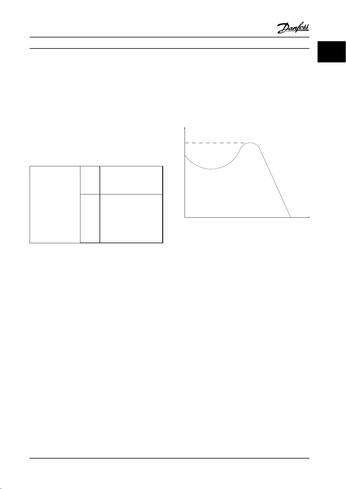
Break-away torque
1
1
Control command
Start and stop the
connected motor with
the LCP or the digital
inputs.
Functions are divided
into two groups.
Functions in group 1
have higher priority
than functions in
group 2.
Table 1.4 Function Groups
Group 1 Reset, Coasting stop, Reset
and Coasting stop, Quick
stop, DC braking, Stop and
the "Off" key
Group 2 Start, Pulse start, Reversing,
Start reversing, Jog and
Freeze output
Motor:
f
JOG
The motor frequency when the jog function is activated
(via digital terminals).
f
M
The motor frequency.
f
MAX
The maximum motor frequency.
f
MIN
The minimum motor frequency.
f
M,N
The rated motor frequency (nameplate data).
I
M
The motor current.
I
M,N
The rated motor current (nameplate data).
n
M,N
The rated motor speed (nameplate data).
P
M,N
The rated motor power (nameplate data).
Figure 1.1 Break-away Torque
η
VLT
The efficiency of the adjustable frequency drive is defined
as the ratio between the power output and the power
input.
Start-disable command
A stop command belonging to the group 1 control
commands - see Table 1.4.
Stop command
See Control commands.
References:
Analog Reference
A signal transmitted to the analog inputs 53 or 54, can be
voltage or current.
Bus Reference
A signal transmitted to the serial communication port (FC
port).
Preset Reference
A defined preset reference to be set from -100% to +100%
of the reference range. Selection of eight preset references
via the digital terminals.
Pulse Reference
A pulse frequency signal transmitted to the digital inputs
(terminal 29 or 33).
MG11BC22 Danfoss A/S © Rev. 06/2014 All rights reserved. 9
Page 12
1
How to Read this Design Gui...
Design Guide
Ref
MAX
Determines the relationship between the reference input
at 100% full scale value (typically 10 V, 20 mA) and the
resulting reference. The maximum reference value set in
3-03 Maximum Reference.
Ref
MIN
Determines the relationship between the reference input
at 0% value (typically 0 V, 0 mA, 4 mA) and the resulting
reference. The minimum reference value set in
3-02 Minimum Reference
Miscellaneous:
Advanced Vector Control
Analog Inputs
The analog inputs are used for controlling various
functions of the adjustable frequency drive.
There are two types of analog inputs:
Current input, 0–20 mA and 4–20 mA
Voltage input, 0–10 V DC.
Analog Outputs
The analog outputs can supply a signal of 0–20 mA,
4–20 mA, or a digital signal.
Automatic Motor Adaptation, AMA
AMA algorithm determines the electrical parameters for
the connected motor at standstill.
Brake Resistor
The brake resistor is a module capable of absorbing the
braking energy generated in regenerative braking. This
regenerative braking energy increases the intermediate
circuit voltage and a brake chopper ensures that the
power is transmitted to the brake resistor.
CT Characteristics
Constant torque characteristics used for screw and scroll
refrigeration compressors.
Digital Inputs
The digital inputs can be used for controlling various
functions of the adjustable frequency drive.
Digital Outputs
The adjustable frequency drive features two solid state
outputs that can supply a 24 V DC (max. 40 mA) signal.
DSP
Digital Signal Processor.
Relay Outputs
The adjustable frequency drive features two programmable
relay outputs.
ETR
Electronic Thermal Relay is a thermal load calculation
based on present load and time. Its purpose is to estimate
the motor temperature.
GLCP
Graphical Local Control Panel (LCP102).
Initializing
If initialization is carried out (14-22 Operation Mode), the
programmable parameters of the adjustable frequency
drive return to their default settings.
Intermittent Duty Cycle
An intermittent duty rating refers to a sequence of duty
cycles. Each cycle consists of an on-load and an off-load
period. The operation can be either periodic duty or nonperiodic duty.
LCP
The Local Control Panel makes up a complete interface for
control and programming of the adjustable frequency
drive. The LCP is detachable and can be installed up to
10 ft [3 m] from the adjustable frequency drive, i.e., in a
front panel by means of the installation kit option.
The LCP is available in two versions:
Numerical LCP101 (NLCP)
•
Graphical LCP102 (GLCP)
•
lsb
Least significant bit.
MCM
Short for Mille Circular Mil, an American measuring unit for
cable cross-section. 1 MCM ≡ 0.00078 in2 [0.5067 mm2].
msb
Most significant bit.
NLCP
Numerical Local Control Panel LCP 101.
Online/Offline Parameters
Changes to online parameters are activated immediately
after the data value is changed. Press [OK] to activate
changes to offline parameters.
PID Controller
The PID controller maintains the desired speed, pressure,
temperature, etc. by adjusting the output frequency to
match the varying load.
RCD
Residual Current Device.
Set-up
Save parameter settings in four set-ups. Change between
the two parameter set-ups and edit one set-up, while
another set-up is active.
SFAVM
Switching pattern called Stator Flux-oriented Asynchronous
Vector Modulation (14-00 Switching Pattern).
10 Danfoss A/S © Rev. 06/2014 All rights reserved. MG11BC22
Page 13
How to Read this Design Gui... Design Guide
1
1
Slip Compensation
The adjustable frequency drive compensates for the motor
slip by giving the frequency a supplement that follows the
measured motor load, keeping the motor speed almost
constant.
Smart Logic Control (SLC)
The SLC is a sequence of user-defined actions executed
when the associated user-defined events are evaluated as
true by the SLC.
Thermistor
A temperature-dependent resistor placed where the
temperature is to be monitored (adjustable frequency drive
or motor).
Trip
A state entered in fault situations, e.g., if the adjustable
frequency drive is subject to an overtemperature or when
the adjustable frequency drive is protecting the motor,
process or mechanism. Restart is prevented until the cause
of the fault has disappeared and the trip state is canceled
by activating reset or, in some cases, by being
programmed to reset automatically. Trip may not be used
for personal safety.
Trip Locked
A state entered in fault situations when the adjustable
frequency drive is protecting itself and requiring physical
intervention, e.g., if the adjustable frequency drive is
subject to a short circuit on the output. A locked trip can
only be canceled by cutting off line power, removing the
cause of the fault, and reconnecting the adjustable
frequency drive. Restart is prevented until the trip state is
canceled by activating reset or, in some cases, by being
programmed to reset automatically. The trip-lock function
may not be used as a personal safety measure.
VT Characteristics
Variable torque characteristics used for pumps and fans.
plus
VVC
If compared with standard voltage/frequency ratio control,
Voltage Vector Control (VVC
plus
) improves the dynamics
and the stability, both when the speed reference is
changed and in relation to the load torque.
60° AVM
Switching pattern called 60° Asynchronous Vector
Modulation (See 14-00 Switching Pattern).
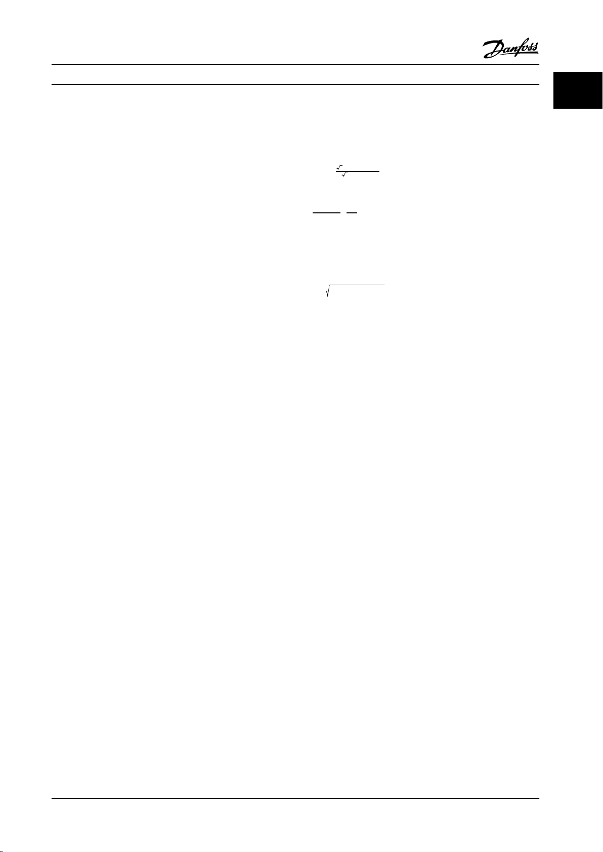
1.1.2
Power Factor
The power factor is the relation between I1 and I
3 × U ×
I
1 ×
COS
Power factor
=
3 × U ×
ϕ
I
RMS
RMS
.
The power factor for 3-phase control:
I
×
cos
ϕ1
1
=
I
1
=
since cos
I
I
RMS
RMS
ϕ1 =1
The power factor indicates to which extent the adjustable
frequency drive imposes a load on the line power supply.
The lower the power factor, the higher the I
RMS
for the
same kW performance.
2
2
2
I
RMS
=
I
+
I
+
1
5
I
7
+ . . +
2
I
n
In addition, a high power factor indicates that the different
harmonic currents are low.
The adjustable frequency drive's built-in DC coils produce a
high power factor, which minimizes the imposed load on
the line power supply.
MG11BC22 Danfoss A/S © Rev. 06/2014 All rights reserved. 11
Page 14
Introduction to VLT® HVAC D...
2
22
Introduction to VLT® HVAC Drive
Design Guide
2.1 Safety
2.1.1 Safety Note
WARNING
The voltage of the adjustable frequency drive is
dangerous whenever connected to line power. Incorrect
installation of the motor, adjustable frequency drive or
serial communication bus may cause death, serious
personal injury or damage to the equipment.
Consequently, the instructions in this manual, as well as
national and local rules and safety regulations, must be
complied with.
Safety Regulations
1. Disconnect the adjustable frequency drive from
line power if repair work is to be carried out.
Make sure that the line power supply has been
disconnected and that the necessary time has
elapsed before removing motor and line power
plugs.
2. The [Stop/Reset] key on the LCP of the adjustable
frequency drive does not disconnect the
equipment from line power and is thus not to be
used as a safety switch.
3. Established correct protective grounding of the
equipment, protect the user against supply
voltage, and protect the motor against overload
in accordance with applicable national and local
regulations.
4. The ground leakage currents are higher than
3.5 mA.
5. Protection against motor overload is set by
1-90 Motor Thermal Protection. If this function is
desired, set 1-90 Motor Thermal Protection to data
value [ETR trip] (default value) or data value [ETR
warning]. Note: The function is initialized at 1.16
x rated motor current and rated motor frequency.
For the North American market: The ETR
functions provide class 20 motor overload
protection in accordance with NEC.
6. Do not remove the plugs for the motor and line
power supply while the adjustable frequency
drive is connected to line power. Make sure that
the line power supply has been disconnected and
that the necessary time has elapsed before
removing motor and line power plugs.
7. Note that the adjustable frequency drive has
more voltage inputs than L1, L2 and L3 when
load sharing (linking of DC intermediate circuit)
and external 24 V DC have been installed. Make
sure that all voltage inputs have been disconnected and that the necessary time has passed
before commencing repair work.
Installation at high altitudes
CAUTION
380–500 V, enclosure types A, B and C: At altitudes
above 6,600 ft [2 km], contact Danfoss regarding PELV.
525–690 V: At altitudes above 6,600 ft [2 km], contact
Danfoss regarding PELV.
WARNING
Warning against unintended start
1. The motor can be stopped with digital
commands, bus commands, references or a
local stop, while the adjustable frequency drive
is connected to line power. If personal safety
considerations make it necessary to ensure that
no unintended start occurs, these stop functions
are not sufficient.
2. While parameters are being changed, the motor
may start. Consequently, the [Reset] key must
always be activated; after which data can be
modified.
3. A motor that has been stopped may start if
faults occur in the electronics of the adjustable
frequency drive, or if a temporary overload or a
fault in the line power or the motor connection
ceases.
WARNING
Touching the electrical parts may be fatal - even after
the equipment has been disconnected from line power.
Also make sure that other voltage inputs have been
disconnected, such as external 24 V DC, load sharing
(linkage of DC intermediate circuit), as well as the motor
connection for kinetic backup. Refer to the Instruction
Manual for further safety guidelines.
12 Danfoss A/S © Rev. 06/2014 All rights reserved. MG11BC22
Page 15
Introduction to VLT® HVAC D...
Design Guide
2.1.2 Caution
WARNING
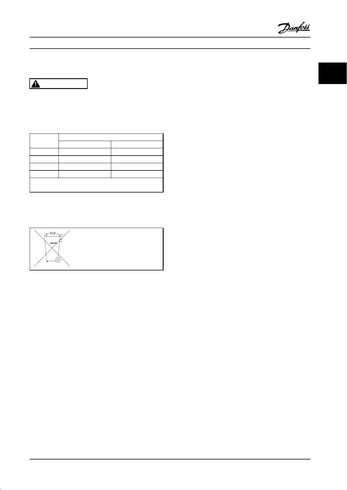
The DC link capacitors remain charged after power has
been disconnected. To avoid an electrical shock hazard,
disconnect the from line power before carrying out
maintenance. Wait at least as follows before doing
service on the adjustable frequency drive:
Voltage [V] Min. waiting time (minutes)
4 15
200–240 1.5–5 hp [1.1–3.7 kW] 7.5–60 hp [5.5–45 kW]
380–480 1.5–10 hp [1.1–7.5 kW] 15–125 hp [11–90 kW]
525–600 1.5–10 hp [1.1–7.5 kW] 15–125 hp [11–90 kW]
525–690 15–125 hp [11–90 kW]
Be aware that there may be high voltage on the DC link even
when the LEDs are turned off.
Table 2.1 Discharge Time
Disposal Instruction
2.1.3
Equipment containing electrical
components may not be disposed of
together with domestic waste.
It must be separately collected with
electrical and electronic waste according
to local and currently valid legislation.
2.2 CE Labeling
2 2
2.2.1 CE Conformity and Labeling
What is CE Conformity and Labeling?
The purpose of CE labeling is to avoid technical trade
obstacles within the EFTA and the EU. The EU has
introduced the CE label as a simple way of showing
whether a product complies with the relevant EU
directives. The CE label says nothing about the specifications or quality of the product. Adjustable frequency
drives are regulated by three EU directives.
The machinery directive (2006/42/EC)
Adjustable frequency drives with the integrated safety
function are now falling under the Machinery Directive.
Danfoss uses CE labels in accordance with the directive
and will issue a declaration of conformity upon request.
Adjustable frequency drives without the safety function do
not fall under the machinery directive. However, if an
adjustable frequency drive is supplied for use in a
machine, we provide information on its safety aspects.
The low-voltage directive (2006/95/EC)
Adjustable frequency drives must be CE labeled in
accordance with the Low-voltage Directive of January 1,
1997. The directive applies to all electrical equipment and
appliances used in the 50–1,000 V AC and the
75–1,500 V DC voltage ranges. Danfoss CE labels in
accordance with the directive and issues a declaration of
conformity upon request.
The EMC directive (2004/108/EC)
EMC is short for electromagnetic compatibility.
The presence of electromagnetic compatibility means that
the mutual interference between different components/
appliances does not affect the way the appliances work.
The EMC directive came into effect January 1, 1996.
Danfoss CE labels in accordance with the directive and
issues a declaration of conformity upon request. To carry
out EMC-compatible installation, see the instructions in this
Design Guide. In addition, Danfoss specifies which
standards our products comply with. Danfoss offers the
filters presented in the specifications and provide other
types of assistance to ensure the optimum EMC result.
The adjustable frequency drive is most often used by
professionals of the trade as a complex component
forming part of a larger appliance, system or installation.
It must be noted that the responsibility for the final EMC
properties of the appliance, system or installation rests
with the installer.
MG11BC22 Danfoss A/S © Rev. 06/2014 All rights reserved. 13
Page 16
Introduction to VLT® HVAC D...
Design Guide
2.2.2 What Is Covered
22
The EU "Guidelines on the Application of Council Directive
2004/108/EC" outline three typical situations of using an
adjustable frequency drive.
1. The adjustable frequency drive is sold directly to
the end user. For such applications, the
adjustable frequency drive must be CE labeled in
accordance with the EMC directive.
2. The adjustable frequency drive is sold as part of a
system. It is being marketed as complete system,
e.g., an air-conditioning system. The complete
system must be CE labeled in accordance with
the EMC directive. The manufacturer can ensure
CE labeling under the EMC directive by testing
the EMC of the system. The components of the
system do not need to be CE marked.
3. The adjustable frequency drive is sold for installation in a plant. It could be a production or a
heating/ventilation plant designed and installed
by professionals of the trade. The adjustable
frequency drive must be CE labeled under the
EMC directive. The finished plant should not bear
the CE mark. However, the installation must
comply with the essential requirements of the
directive. This is assumed by using appliances
and systems that are CE labeled under the EMC
directive
Danfoss Adjustable frequency drive
2.2.3
The CE label also applies to the EMC directive provided
that the instructions for EMC-compatible installation and
filtering are followed. On this basis, a declaration of
conformity in accordance with the EMC directive is issued.
This Design Guide offers detailed instructions for installation
to ensure EMC-compatible installation. Furthermore,
Danfoss specifies with what the different products comply.
Danfoss provides other types of assistance that can help
obtain the best EMC result.
2.2.4 Compliance with EMC Directive
2004/108/EC
As mentioned, the adjustable frequency drive is mostly
used by professionals of the trade as a complex
component forming part of a larger appliance, system or
installation. Note that the responsibility for the final EMC
properties of the appliance, system or installation rests
with the installer. As an aid to the installer, Danfoss has
prepared EMC installation guidelines for the Power Drive
system. The standards and test levels stated for Power
Drive systems are complied with, provided that the EMCcompatible instructions for installation are followed, see.
2.3
Air humidity
The adjustable frequency drive has been designed to meet
the IEC/EN 60068-2-3 standard, EN 50178 pkt. 9.4.2.2 at
122 °F [50 °C].
2.4
Aggressive Environments
and CE Labeling
An adjustable frequency drive contains a large number of
The purpose of CE labeling is to facilitate trade within the
EU and EFTA.
mechanical and electronic components. All are to some
extent vulnerable to environmental effects.
However, CE labeling may cover many different specifications. Thus, check what a given CE label specifically
covers.
The covered specifications can be very different and a CE
label may therefore give the installer a false feeling of
security when using an adjustable frequency drive as a
component in a system or an appliance.
Danfoss CE labels the adjustable frequency drives in
accordance with the low-voltage directive. This means that
if the adjustable frequency drive is installed correctly,
Danfoss guarantees compliance with the low-voltage
directive. Danfoss issues a declaration of conformity that
confirms our CE labeling in accordance with the lowvoltage directive.
14 Danfoss A/S © Rev. 06/2014 All rights reserved. MG11BC22
CAUTION
Do not install the adjustable frequency drive in
environments with airborne liquids, particles, or gases
capable of affecting and damaging the electronic
components. Failure to take the necessary protective
measures increases the risk of stoppages, thus reducing
the life of the adjustable frequency drive.
Degree of protection as per IEC 60529
The Safe Torque Off function may only be installed and
operated in a control cabinet with degree of protection
IP54 or higher (or equivalent environment). This is required
to avoid cross faults and short circuits between terminals,
connectors, tracks and safety-related circuitry caused by
foreign objects.
Page 17
Introduction to VLT® HVAC D... Design Guide
Liquids can be carried through the air and condense in the
adjustable frequency drive and may cause corrosion of
components and metal parts. Steam, oil, and salt water
may cause corrosion of components and metal parts. In
such environments, use equipment with enclosure rating IP
54/55. As an extra protection, coated printed circuit boards
can be ordered as an option.
Airborne particles such as dust may cause mechanical,
electrical or thermal failure in the adjustable frequency
drive. A typical indicator of excessive levels of airborne
particles is the presence of dust particles around the
adjustable frequency drive fan. In very dusty environments,
use equipment with enclosure rating IP 54/55 or a cabinet
for IP 00/IP 20/TYPE 1 equipment.
In environments with high temperatures and humidity,
corrosive gases such as sulfur, nitrogen, and chlorine
compounds cause chemical processes on the adjustable
frequency drive components.
Such chemical reactions rapidly affect and damage the
electronic components. In such environments, mount the
equipment in a cabinet with fresh air ventilation, keeping
aggressive gases away from the adjustable frequency drive.
An extra protection in such areas is a coating of the
printed circuit boards, which can be ordered as an option.
NOTICE!
Mounting adjustable frequency drives in aggressive
environments increases the risk of stoppages and considerably reduces the life of the adjustable frequency drive.
Before installing the adjustable frequency drive, check the
ambient air for liquids, particles and gases. This is done by
observing existing installations in this environment. Typical
indicators of harmful airborne liquids are water or oil on
metal parts, or corrosion of metal parts.
Excessive dust particle levels are often found on installation cabinets and existing electrical installations. One
indicator of aggressive airborne gases is the blackening of
copper rails and cable ends on existing installations.
D and E enclosure types have a stainless steel backchannel
option to provide additional protection in aggressive
environments. Proper ventilation is still required for the
internal components of the adjustable frequency drive.
Contact Danfoss for additional information.
2.5
Vibration and Shock
The adjustable frequency drive has been tested according
to the procedure based on the shown standards:
IEC/EN 60068-2-6: Vibration (sinusoidal) - 1970
•
IEC/EN 60068-2-64: Vibration, broad-band random
•
The adjustable frequency drive complies with requirements
that exist for units mounted on the walls and floors of
production premises, as well as in panels bolted to walls or
floors.
2.6 Safe Torque Off
The FC 102 can perform the safety function Safe Torque Off
(STO, as defined by EN IEC 61800-5-21) and Stop Category 0
(as defined in EN 60204-12).
Before integrating and using Safe Torque Off in an installation, a thorough risk analysis on the installation must be
carried out in order to determine whether the Safe Torque
Off functionality and safety levels are appropriate and
sufficient. It is designed and approved as suitable for the
requirements of:
Category 3 in EN ISO 13849-1
•
Performance Level "d" in EN ISO 13849-1:2008
•
SIL 2 Capability in IEC 61508 and EN 61800-5-2
•
SILCL 2 in EN 62061
•
1) Refer to EN IEC 61800-5-2 for details of Safe torque off
(STO) function.
2) Refer to EN IEC 60204-1 for details of stop category 0
and 1.
Activation and Termination of Safe Torque Off
The Safe Torque Off (STO) function is activated by
removing the voltage at Terminal 37 of the Safe Inverter.
By connecting the Safe Inverter to external safety devices
providing a safe delay, an installation for a Safe Torque Off
Category 1 can be obtained. The Safe Torque Off function
of FC 102 can be used for asynchronous, synchronous
motors and permanent magnet motors. See examples in
chapter 2.6.1 Terminal 37 Safe Torque Off Function.
WARNING
After installation of Safe Torque Off (STO), a commissioning test as specified in section Safe Torque Off
Commissioning Test must be performed. A passed
commissioning test is mandatory after first installation
and after each change to the safety installation.
2 2
MG11BC22 Danfoss A/S © Rev. 06/2014 All rights reserved. 15
Page 18
Introduction to VLT® HVAC D...
Design Guide
Safe Torque Off Technical Data
22
The following values are associated to the different types
of safety levels:
Reaction time for T37
Maximum reaction time: 20 ms
•
Reaction time = delay between de-energizing the STO
input and switching off the output bridge.
Data for EN ISO 13849-1
Performance Level "d"
•
MTTFd (Mean Time To Dangerous Failure):
•
14,000 years
DC (Diagnostic Coverage): 90%
•
Category 3
•
Lifetime 20 years
•
Data for EN IEC 62061, EN IEC 61508, EN IEC 61800-5-2
SIL 2 Capability, SILCL 2
•
PFH (Probability of dangerous Failure per Hour) =
•
1E-10/h
SFF (Safe Failure Fraction) > 99%
•
HFT (Hardware Fault Tolerance) = 0
•
(1001 architecture)
Lifetime 20 years
•
Data for EN IEC 61508 low demand
PFDavg for 1-year proof test: 1E-10
•
PFDavg for 3-year proof test: 1E-10
•
PFDavg for 5-year proof test: 1E-10
•
No maintenance of the STO functionality is needed.
Take security measures, e.g., only skilled personnel must be
able to access and install in closed cabinets.
SISTEMA Data
Danfoss provides functional safety data via a data library
for use with the SISTEMA calculation tool from IFA
(Institute for Occupational Safety and Health of the
German Social Accident Insurance), as well as data for
manual calculation. The library is complete and continually
extended.
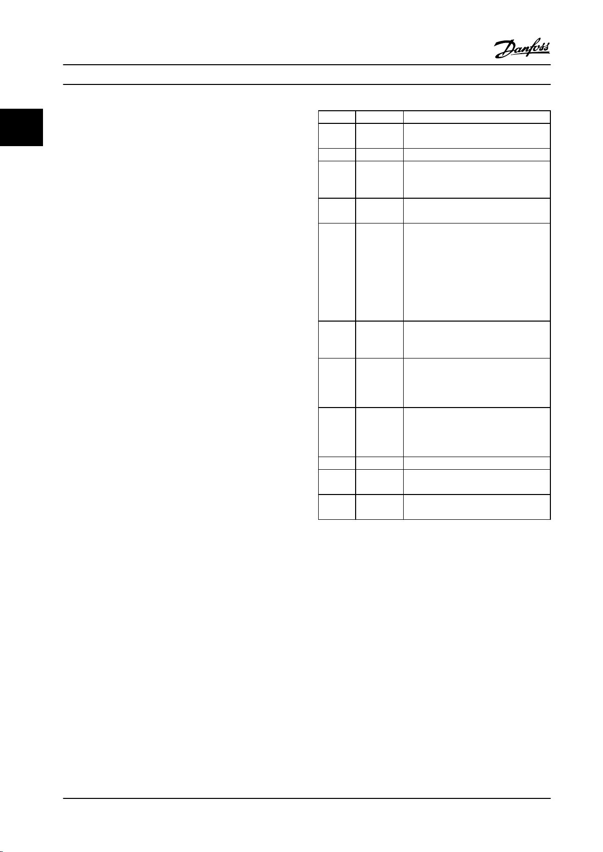
Abbrev. Ref. Description
Cat. EN ISO
13849-1
FIT Failure In Time: 1E-9 hours
HFT IEC 61508 Hardware Fault Tolerance: HFT = n
MTTFd EN ISO
13849-1
PFH IEC 61508 Probability of Dangerous Failures per
PFD IEC 61508 Average probability of failure on
PL EN ISO
13849-1
SFF IEC 61508 Safe Failure Fraction [%]; Percentage
SIL IEC 61508 Safety Integrity Level
STO EN
61800-5-2
SS1 EN 61800
-5-2
Table 2.2 Abbreviations Related to Functional Safety
Terminal 37 Safe Torque Off Function
2.6.1
The FC 102 is available with Safe Torque Off functionality
via control terminal 37. Safe Torque Off disables the
control voltage of the power semiconductors of the
adjustable frequency drive output stage which in turn
prevents generating the voltage required to rotate the
motor. When the Safe Torque Off (T37) is activated, the
adjustable frequency drive issues an alarm, trips the unit,
and coasts the motor to a stop. Manual restart is required.
The Safe Torque Off function can be used for stopping the
adjustable frequency drive in emergency stop situations. In
the normal operating mode when Safe Torque Off is not
required, use the adjustable frequency drive’s regular stop
function instead. When automatic restart is used – the
requirements according to ISO 12100-2 paragraph 5.3.2.5
must be fulfilled.
Category, level “B, 1-4”
means that n+1 faults could cause a
loss of the safety function
Mean Time To Failure - dangerous. Unit:
years
Hour. This value shall be considered if
the safety device is operated in high
demand (more often than once per
year) or continuous mode of operation,
where the frequency of demands for
operation made on a safety-related
system is greater than one per year
demand, value used for low demand
operation
Discrete level used to specify the ability
of safety related parts of control
systems to perform a safety function
under foreseeable conditions. Levels a-e
part of safe failures and dangerous
detected failures of a safety function or
a subsystem related to all failures
Safe Torque Off
Safe Stop 1
16 Danfoss A/S © Rev. 06/2014 All rights reserved. MG11BC22
Page 19
Introduction to VLT® HVAC D...
Design Guide
Liability Conditions
It is the user’s responsibility to ensure that personnel
installing and operating the Safe Torque Off function:
Read and understand the safety regulations
•
concerning health and safety/accident prevention
Understand the generic and safety guidelines
•
given in this description and the extended
description in the Design Guide
Have a good knowledge of the generic and safety
•
standards applicable to the specific application
Standards
Use of Safe Torque Off on terminal 37 requires that the
user satisfies all provisions for safety including relevant
laws, regulations and guidelines. The optional Safe Torque
Off function complies with the following standards.
IEC 60204-1: 2005 category 0 – uncontrolled stop
IEC 61508: 1998 SIL2
IEC 61800-5-2: 2007 – safe torque off (STO)
function
IEC 62061: 2005 SIL CL2
ISO 13849-1: 2006 Category 3 PL d
ISO 14118: 2000 (EN 1037) – prevention of
unexpected startup
The information and instructions of the Instruction Manual
are not sufficient for a proper and safe use of the Safe
Torque Off functionality. The related information and
instructions in the relevant Design Guide must be followed.
Protective Measures
Safety engineering systems may only be installed
•
and commissioned by qualified and skilled
personnel
The unit must be installed in an IP54 cabinet or
•
in an equivalent environment. In special
applications, a higher IP degree may be necessary
The cable between terminal 37 and the external
•
safety device must be short-circuit-protected
according to ISO 13849-2 table D.4
If any external forces influence the motor axis
•
(e.g., suspended loads), additional measures
(e.g., a safety holding brake) are required to
eliminate hazards.
Safe Torque Off Installation and Set-up
WARNING
SAFE TORQUE OFF FUNCTION!
The Safe Torque Off function does NOT isolate AC line
voltage to the adjustable frequency drive or auxiliary
circuits. Perform work on electrical parts of the
adjustable frequency drive or the motor only after
isolating the AC line voltage supply and waiting the
length of time specified under Safety in this manual.
Failure to isolate the AC line voltage supply from the
unit and waiting the time specified could result in death
or serious injury.
It is not recommended to stop the adjustable
•
frequency drive by using the Safe Torque Off
function. If a running adjustable frequency drive
is stopped by using the function, the unit trips
and stops by coasting. If this is not acceptable,
e.g., causes danger, the adjustable frequency
drive and machinery must be stopped using the
appropriate stopping mode before using this
function. Depending on the application, a
mechanical brake may be required.
Concerning synchronous and permanent magnet
•
motor adjustable frequency drives in case of a
multiple IGBT power semiconductor failure: In
spite of the activation of the Safe Torque Off
function, the adjustable frequency drive system
can produce an alignment torque which
maximally rotates the motor shaft by 180/p
degrees. p denotes the pole pair number.
This function is suitable for performing
•
mechanical work on the adjustable frequency
drive system or affected area of a machine only.
It does not provide electrical safety. This function
should not be used as a control for starting
and/or stopping the adjustable frequency drive.
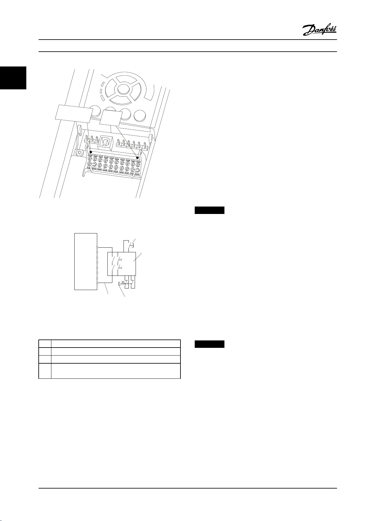
Meet the following requirements to perform a safe installation of the adjustable frequency drive:
1. Remove the jumper wire between control
terminals 37 and 12 or 13. Cutting or breaking
the jumper is not sufficient to avoid shortcircuiting. (See jumper on Figure 2.1.)
2. Connect an external safety monitoring relay via a
NO safety function (the instruction for the safety
device must be followed) to terminal 37 (Safe
Torque Off) and either terminal 12 or 13 (24 V
DC). The Safety monitoring relay must comply
with Category 3/PL “d” (ISO 13849-1) or SIL 2
(EN 62061).
2 2
MG11BC22 Danfoss A/S © Rev. 06/2014 All rights reserved. 17
Page 20
12/13
37
130BA874.10
12
37
3
2
FC
4
1
130BB967.10
Introduction to VLT® HVAC D...
22
Figure 2.1 Jumper between Terminal 12/13 (24 V) and 37
Design Guide
Safe Torque Off Commissioning Test
After installation and before first operation, perform a
commissioning test of the installation making use of Safe
Torque Off. Also, perform the test after each modification
of the installation.
Example with STO
A safety relay evaluates the E-Stop button signals and
triggers an STO function on the adjustable frequency drive
in the event of an activation of the E-Stop button (See
Figure 2.3). This safety function corresponds to a category 0
stop (uncontrolled stop) in accordance with IEC 60204-1. If
the function is triggered during operation, the motor runs
down in an uncontrolled manner. The power to the motor
is safely removed, so that no further movement is possible.
It is not necessary to monitor plant at a standstill. If an
external force effect is to be anticipated, provide additional
measures to safely prevent any potential movement
(e.g., mechanical brakes).
NOTICE!
For all applications with Safe Torque Off, it is important
that short circuit in the wiring to T37 can be excluded.
This can be done as described in EN ISO 13849-2 D4 by
the use of protected wiring, (shielded or segregated).
Figure 2.2 Installation to Achieve a Stopping Category 0
(EN 60204-1) with Safety Cat. 3/PL “d” (ISO 13849-1) or
SIL 2 (EN 62061).
1 Safety relay (cat. 3, PL d or SIL2
2 Emergency stop button
3 Reset button
4 Short-circuit protected cable (if not inside installation
IP54 cabinet)
Table 2.3 Legend to Figure 2.2
Example with SS1
SS1 correspond to a controlled stop, stop category 1
according to IEC 60204-1 (see Figure 2.4). When activating
the safety function, a normal controlled stop is performed.
This can be activated through terminal 27. After the safe
delay time has expired on the external safety module, the
STO is triggered and terminal 37 is set low. Ramp-down is
performed as configured in the adjustable frequency drive.
If the adjustable frequency drive is not stopped after the
safe delay time, the activation of STO coasts the adjustable
frequency drive.
NOTICE!
When using the SS1 function, the brake ramp of the
adjustable frequency drive is not monitored with respect
to safety.
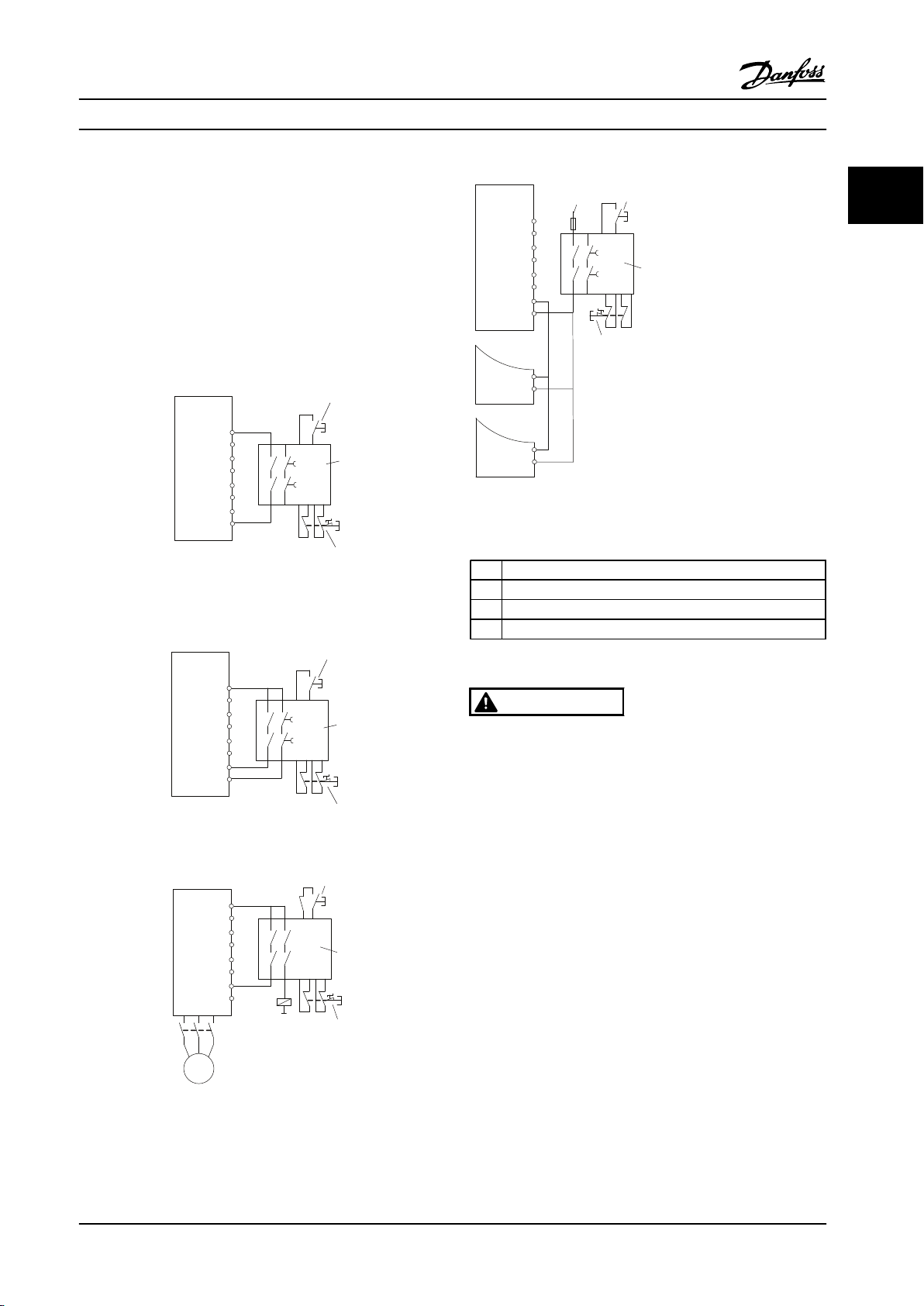
Example with Category 4/PL e application
Where the safety control system design requires two
channels for the STO function to achieve Category 4/PL e,
one channel can be implemented by Safe Torque Off T37
(STO) and the other by a contactor which may be
connected in either the adjustable frequency drive input or
output power circuits and controlled by the safety relay
(see Figure 2.5). The contactor must be monitored through
an auxiliary guided contact and connected to the reset
input of the safety relay.
18 Danfoss A/S © Rev. 06/2014 All rights reserved. MG11BC22
Page 21
12
37
FC
1
2
3
130BB968.10
FC
12
18
37
3
1
2
130BB969.10
12
FC
37
K1
K1
K1
130BB970.10
2
3
1
12
37
FC
20
130BC001.10
FC
FC
20
20
37
37
3
1
2
4
Introduction to VLT® HVAC D...
Design Guide
Paralleling of Safe Torque Off inputs via one safety relay
Safe Torque Off inputs T37 (STO) may be connected
directly if the situation is required to control multiple
adjustable frequency drives from the same control line via
one safety relay (see Figure 2.6). Connecting inputs
increases the probability of a fault in the unsafe direction,
since a fault in one adjustable frequency drive might result
in all adjustable frequency drives becoming enabled. The
probability of a fault for T37 is so low, that the resulting
probability still meets the requirements for SIL2.
2 2
Figure 2.6 Paralleling of Multiple Adjustable Frequency
Drives Example
Figure 2.3 STO Example
1 Safety relay
2 Emergency stop button
3 Reset button
4 24 V DC
Table 2.4 Legend to Figure 2.3 to Figure 2.6
WARNING
Safe Torque Off activation (i.e., removal of 24 V DC
voltage supply to terminal 37) does not provide
electrical safety. The Safe Torque Off function itself is
therefore not sufficient to implement the Emergency Off
function as defined by EN 60204-1. Emergency Off
Figure 2.4 SS1 Example
requires measures of electrical isolation, e.g., by
switching off line power via an additional contactor.
1. Activate the Safe Torque Off function by
removing the 24 V DC voltage supply to the
terminal 37.
2. After activation of Safe Torque Off (i.e., after the
response time), the adjustable frequency drive
coasts (stops creating a rotational field in the
motor). The response time is typically shorter
than 10 ms for the complete performance range
of the adjustable frequency drive.
Figure 2.5 STO Category 4 Example
MG11BC22 Danfoss A/S © Rev. 06/2014 All rights reserved. 19
Page 22
Introduction to VLT® HVAC D... Design Guide
The adjustable frequency drive is guaranteed not to restart
22
creation of a rotational field by an internal fault (in
accordance with Cat. 3 PL d acc. EN ISO 13849-1 and SIL 2
acc. EN 62061). After activation of Safe Torque Off, the
adjustable frequency drive display shows the text Safe
Torque Off activated. The associated help text says "Safe
Torque Off has been activated". This means that the Safe
Torque Off has been activated, or that normal operation
has not been resumed yet after Safe Torque Off activation.
NOTICE!
The requirements of Cat. 3/PL “d” (ISO 13849-1) are only
fulfilled while 24 V DC supply to terminal 37 is kept
removed or low by a safety device, which itself fulfills
Cat. 3/PL “d” (ISO 13849-1). If external forces act on the
motor, e.g., in case of vertical axis (suspended loads) and an unwanted movement, for example caused by
gravity, could cause a hazard, the motor must not be
operated without additional measures for fall protection.
For example, mechanical brakes must be installed
additionally.
To resume operation after activation of Safe Torque Off,
first reapply 24 V DC voltage to terminal 37 (text Safe
Torque Off activated is still displayed), then create a reset
signal (via bus, Digital I/O, or [Reset] key on inverter).
By default, the Safe Torque Off functions is set to an
Unintended Restart Prevention behavior. This means, in
order to terminate Safe Torque Off and resume normal
operation, the 24 V DC must first be reapplied to Terminal
37. Subsequently, send a reset signal (via Bus, Digital I/O,
or [Reset] key).
WARNING
Automatic Restart Behavior is only allowed in one of the
two situations:
1. The Unintended Restart Prevention is
implemented by other parts of the Safe Torque
Off installation.
2. A presence in the dangerous zone can be
physically excluded when Safe Torque Off is not
activated. In particular, paragraph 5.3.2.5 of ISO
12100-2 2003 must be observed.
2.6.2 Installation of External Safety Device
in Combination with MCB 112
If the ex-certified thermistor module MCB 112, which uses
Terminal 37 as its safety-related switch-off channel, is
connected, then the output X44/12 of MCB 112 must be
AND-ed with the safety-related sensor (such as emergency
stop button, safety-guard switch, etc.) that activates Safe
Torque Off. This means that the output to Safe Torque Off
terminal 37 is HIGH (24 V) only if both the signal from MCB
112 output X44/12 and the signal from the safety-related
sensor are HIGH. If at least one of the two signals is LOW,
the output to Terminal 37 must be LOW, too. The safety
device with this AND logic itself must conform to IEC
61508, SIL 2. The connection from the output of the safety
device with safe AND logic to Safe Torque Off terminal 37
must be short-circuit protected. See Figure 2.7.
The Safe Torque Off function can be set to an Automatic
Restart Behavior by setting the value of 5-19 Terminal 37
Safe Stop from default value [1] to value [3]. If a MCB 112
Option is connected to the adjustable frequency drive,
then Automatic Restart Behavior is set by values [7] and
[8].
Automatic Restart means that Safe Torque Off is
terminated and normal operation is resumed as soon as
the 24 V DC is applied to Terminal 37, and no reset signal
is required.
20 Danfoss A/S © Rev. 06/2014 All rights reserved. MG11BC22
Page 23
130BA967.11
121110987654321
37203332292 719181312
DI DI
SIL 2
Safe St op
Digital Input
e.g. Par 5-15
PTC
Sensor
X44/
Par. 5-19
Terminal 37 Safe Stop
Safety Device
Safe I nput
Safe Out put
Safe AN D Input
Manual R estart
PTC Thermist or Card
MCB112
Non- Haz ardous AreaHazardous
Area
Introduction to VLT® HVAC D...
Design Guide
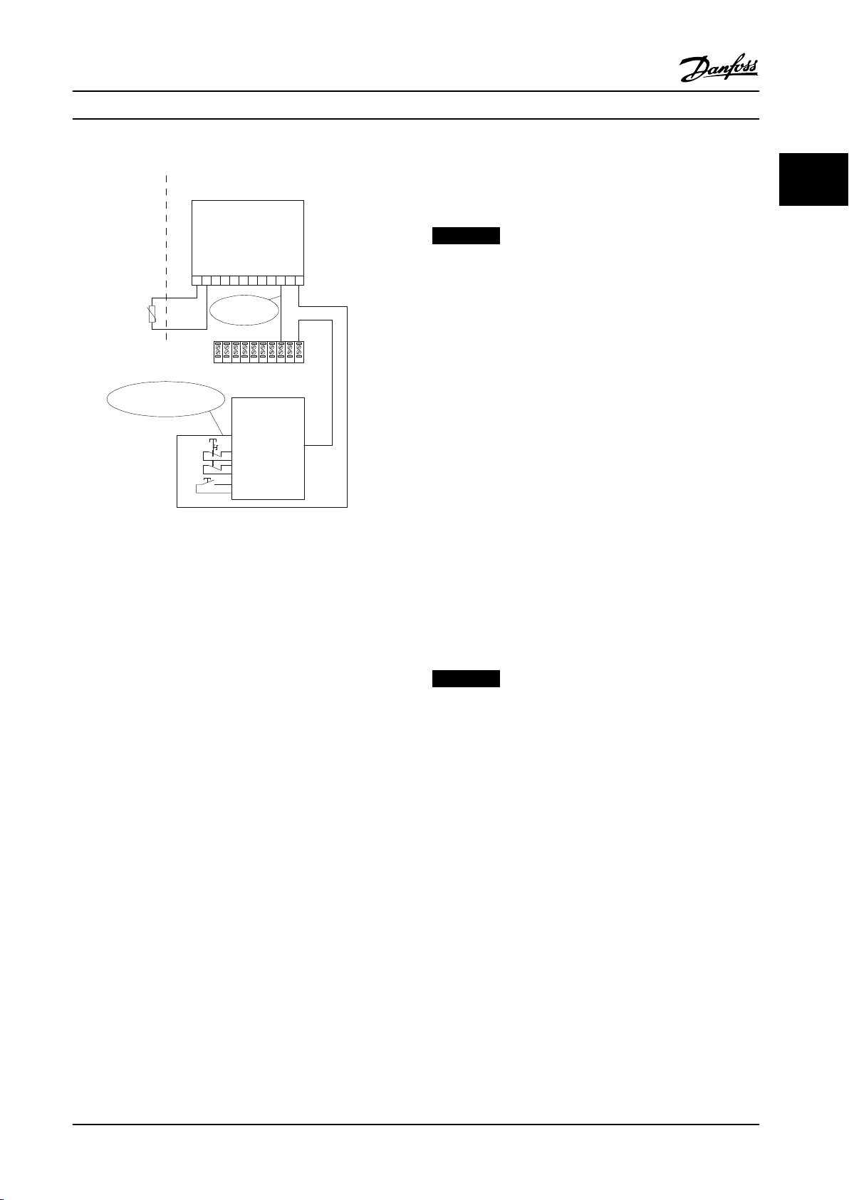
Figure 2.7 Figure of the essential aspects for installing a
combination of a Safe Torque Off application and an
MCB 112 application. The diagram shows a Restart input for
the external Safety Device. This means that in this installation,
5-19 Terminal 37 Safe Stop might be set to value [7] PTC 1 &
Relay W or [8] [8] PTC 1 & Relay A/W. Refer to MCB 112
Instruction Manual for further details.
Selections
[6] PTC 1 & Relay A to [9] PTC 1 & Relay W/A must
be selected for the combination of external safety device
and MCB 112.
NOTICE!
Note that selections [7] PTC 1 & Relay W and [8] PTC 1 &
Relay A/W open up for automatic restart when the
external safety device is de-activated again.
This is only allowed in the following cases:
The unintended restart prevention is
•
implemented by other parts of the Safe Torque
Off installation.
A presence in the dangerous zone can be
•
physically excluded when Safe Torque Off is not
activated. In particular, paragraph 5.3.2.5 of ISO
12100-2 2003 must be observed.
See MCB 112 Instruction Manual for further information.
Safe Torque Off Commissioning Test
2.6.3
After installation and before first operation, perform a
commissioning test of an installation or application making
use of Safe Torque Off.
Moreover, perform the test after each modification of the
installation or application which the Safe Torque Off is part
of.
2 2
Parameter settings for external safety device in
combination with MCB112
If MCB 112 is connected, then additional selections ([4] PTC
1 Alarm to [9] PTC 1 & Relay W/A) become possible for
5-19 Terminal 37 Safe Stop. Selections [1] Safe Torque Off
Alarm and [3] Safe Torque Off Warning are still available but
are not to be used as these are for installations without
MCB 112 or any external safety devices. If [1] Safe Torque
Off Alarm or [3] Safe Torque Off Warning should be selected
by mistake and MCB 112 is triggered, then the adjustable
frequency drive reacts with an alarm ”Dangerous Failure
[A72]” and coasts the adjustable frequency drive safely,
without Automatic Restart. Selections [4] PTC 1 Alarm and
[5] PTC 1 Warning are not to be selected when an external
safety device is used. These selections are for when only
MCB 112 uses the Safe Torque Off. If selection [4] PTC 1
Alarm or [5] PTC 1 Warning is selected by mistake and the
external safety device triggers Safe Torque Off, the
adjustable frequency drive issues an alarm ”Dangerous
Failure [A72]” and coasts the adjustable frequency drive
safely, without Automatic Restart.
MG11BC22 Danfoss A/S © Rev. 06/2014 All rights reserved. 21
NOTICE!
A passed commissioning test is mandatory after first
installation and after each change to the safety installation.
The commissioning test (select one of cases 1 or 2 as
applicable):
Case 1: Restart prevention for Safe Torque Off is
required (i.e., Safe Torque Off only where 5-19 Terminal
37 Safe Stop is set to default value [1], or combined Safe
Torque Off and MCB112 where 5-19 Terminal 37 Safe
Stop is set to [6] or [9]):
1.1 Remove the 24 V DC voltage supply to
terminal 37 using the interrupt device while the
motor is driven by the FC 102 (i.e., the line power
supply is not interrupted). The test step is passed
if the motor reacts with a coast and the
mechanical brake (if connected) is activated, and
if an LCP is mounted, the alarm “Safe Torque Off
[A68]” is displayed.
Page 24
Introduction to VLT® HVAC D... Design Guide
1.2 Send reset signal (via Bus, Digital I/O, or
22
The commissioning test is passed if all four test steps 1.1,
1.2, 1.3 and 1.4 are passed.
Case 2: Automatic Restart of Safe Torque Off is wanted
and allowed (i.e., Safe Torque Off only where
5-19 Terminal 37 Safe Stop is set to [3], or combined Safe
Torque Off and MCB112 where 5-19 Terminal 37 Safe
Stop is set to [7] or [8]):
The test step is passed if the motor becomes operational
again. The commissioning test is passed if both test steps
2.1 and 2.2 are passed.
[Reset] key). The test step is passed if the motor
remains in the Safe Torque Off state, and the
mechanical brake (if connected) remains
activated.
1.3 Reapply 24 V DC to terminal 37. The test step
is passed if the motor remains in the coasted
state, and the mechanical brake (if connected)
remains activated.
1.4 Send reset signal (via Bus, Digital I/O, or
[Reset] key). The test step is passed if the motor
becomes operational again.
2.1 Remove the 24 V DC voltage supply to
terminal 37 by the interrupt device while the
motor is driven by the FC 102 (i.e., line power
supply is not interrupted). The test step is passed
if the motor reacts with a coast and the
mechanical brake (if connected) is activated, and
if an LCP is mounted, the warning “Safe Torque
Off [W68]” is displayed.
2.2 Reapply 24 V DC to terminal 37.
Compared to alternative control systems and technologies,
an adjustable frequency drive is the optimum energy
control system for controlling fan and pump systems.
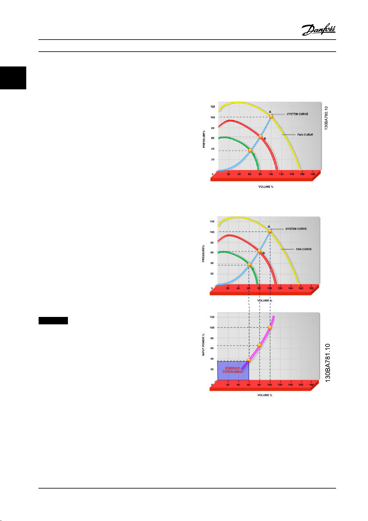
Figure 2.8 Fan Curves (A, B and C) for Reduced Fan Volumes
NOTICE!
See warning on the restart behavior in
chapter 2.6.1 Terminal 37 Safe Torque Off Function.
2.7 Advantages
2.7.1 Why use an adjustable frequency
drive for controlling fans and pumps?
An adjustable frequency drive takes advantage of the fact
that centrifugal fans and pumps follow the laws of proportionality for such fans and pumps. For further information,
see the text and figure The Laws of Proportionality.
2.7.2
The Clear Advantage - Energy Savings
The advantage of using an adjustable frequency drive for
controlling the speed of fans or pumps lies in the
electricity savings.
22 Danfoss A/S © Rev. 06/2014 All rights reserved. MG11BC22
Figure 2.9 When Using an Adjustable Frequency Drive to
Reduce Fan Capacity to 60% - More Than 50% Energy
Savings may Be Obtained in Typical Applications.
Page 25
n
100%
50%
25%
12,5%
50% 100%
80%
80%
175HA208.10
Power ~n
3
Pressure ~n
2
Flow ~n
130BA782.10
Discharge
damper
Less energy savings
IGV
Costlier installation
Maximum energy savings
Introduction to VLT® HVAC D... Design Guide
2.7.3 Example of Energy Savings
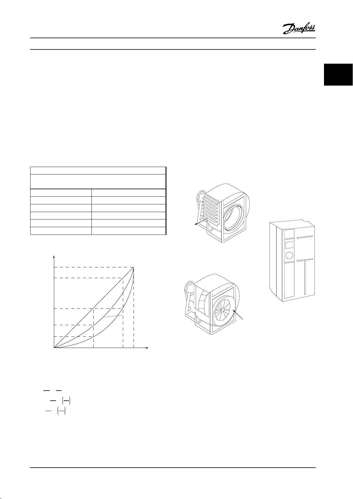
As shown in the figure (the laws of proportionality), the
flow is controlled by changing the RPM. By reducing the
rated speed by only 20%, the flow is also reduced by 20%.
This is because the flow is directly proportional to the
RPM. The consumption of electricity, however, is reduced
by 50%.
If the system in question only needs to be able to supply a
flow corresponding to 100% a few days each year, while
the average is below 80% of the rated flow for the
remainder of the year, the amount of energy saved is even
greater than 50%.
The laws of proportionality
Figure 2.10 describes the dependence of flow, pressure and
power consumption on RPM.
Q = Flow P = Power
Q1 = Rated flow P1 = Rated power
Q2 = Reduced flow P2 = Reduced power
H = Pressure n = Speed regulation
H1 = Rated pressure n1 = Rated speed
H2 = Reduced pressure n2 = Reduced speed
Comparison of Energy Savings
2.7.4
The Danfoss adjustable frequency drive solution offers
major savings compared with traditional energy saving
solutions. This is because the adjustable frequency drive is
able to control fan speed according to thermal load on the
system and the fact that the adjustable frequency drive
has a built-in facility that enables the adjustable frequency
drive to function as a Building Management System, BMS.
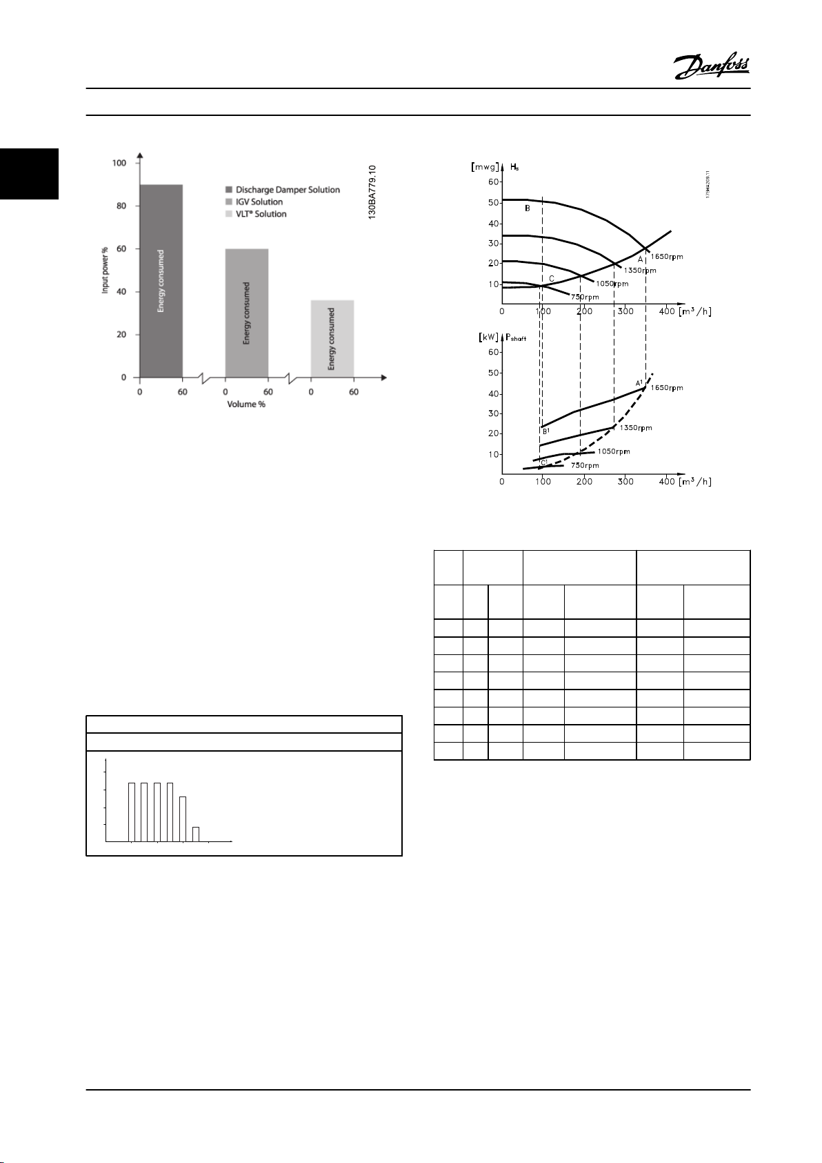
Figure 2.12 shows typical energy savings obtainable with
three well-known solutions when fan volume is reduced to,
e.g., 60%.
Figure 2.12 shows more than 50% energy savings can be
achieved in typical applications.
2 2
Table 2.5 Abbreviations Used in Equation
Figure 2.10 The Dependence of Flow, Pressure and Power
Consumption on RPM
Q
n
1
Flow
:
Pressure
Power
:
1
=
Q
n
2
2
H
n
2
1
H
=
1
=
n
2
2
n
3
1
n
2
:
P
1
P
2
Figure 2.11 The Three Common Energy Saving Systems
MG11BC22 Danfoss A/S © Rev. 06/2014 All rights reserved. 23
Page 26
500
[h]
t
1000
1500
2000
200100 300
[m
3
/h]
400
Q
175HA210.11
Introduction to VLT® HVAC D...
Design Guide
22
Figure 2.12 Discharge dampers reduce power consumption
somewhat. Inlet guide vans offer a 40% reduction but are
expensive to install. The Danfoss adjustable frequency drive
solution reduces energy consumption with more than 50%
and is easy to install.
Figure 2.13 Example with Varying Flow
Example with Varying Flow over 1
2.7.5
Year
The example below is calculated on the basis of pump
characteristics obtained from a pump datasheet.
The result obtained shows energy savings in excess of 50%
at the given flow distribution over a year. The payback
period depends on the price per kWh and price of
adjustable frequency drive. In this example, it is less than a
year when compared with valves and constant speed.
Flow distribution over 1 year
P
shaft=Pshaft output
Table 2.6 Energy Savings
Distri-
m3/
bution
h
% Hours Power Consumption Power Consump-
Valve regulation Adjustable frequency
drive control
tion
A1–B
1
kWh A1–C
kWh
1
350 5 438 42.5 18.615 42.5 18.615
300 15 1314 38.5 50.589 29.0 38.106
250 20 1752 35.0 61.320 18.5 32.412
200 20 1752 31.5 55.188 11.5 20.148
150 20 1752 28.0 49.056 6.5 11.388
100 20 1752 23.0 40.296 3.5 6.132
100 8760 275.064 26.801
Σ
Table 2.7 Consumption
Better Control
2.7.6
If an adjustable frequency drive is used for controlling the
flow or pressure of a system, improved control is obtained.
An adjustable frequency drive can vary the speed of the
fan or pump, thereby obtaining variable control of flow
and pressure.
Furthermore, an adjustable frequency drive can quickly
adapt the speed of the fan or pump to new flow or
pressure conditions in the system.
Simple control of process (flow, level, or pressure) utilizing
the built-in PID control.
24 Danfoss A/S © Rev. 06/2014 All rights reserved. MG11BC22
Page 27
Full load
% Full load current
& speed
500
100
0
0 12,5 25 37,5 50Hz
200
300
400
600
700
800
4
3
2
1
175HA227.10
Introduction to VLT® HVAC D...
2.7.7
Cos φ Compensation
Design Guide
Generally speaking, the VLT® HVAC Drive has a cos φ of 1
and provides power factor correction for the cos φ of the
motor, which means that there is no need to make
allowance for the cos φ of the motor when sizing the
power factor correction unit.
2.7.8 Star/Delta Starter or Soft-starter not
Required
When larger motors are started, it is necessary in many
countries to use equipment that limits the start-up current.
In more traditional systems, a star/delta starter or softstarter is widely used. Such motor starters are not required
if an adjustable frequency drive is used.
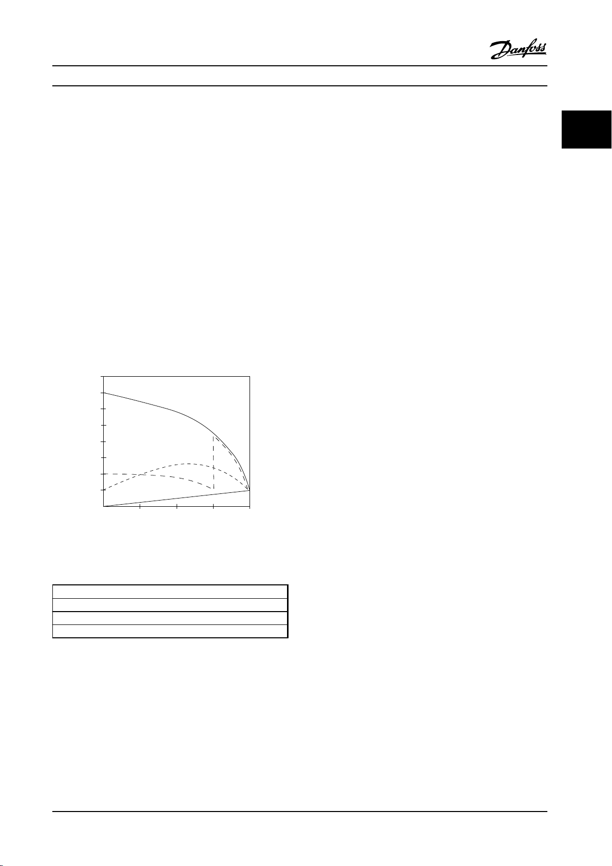
As illustrated in Figure 2.14, an adjustable frequency drive
does not consume more than rated current.
2 2
Figure 2.14 An Adjustable Frequency Drive Does Not
Consume More Than Rated Current
1 VLT® HVAC Drive
2 Star/delta starter
3 Soft-starter
4 Start directly on line power
Table 2.8 Legend to Figure 2.14
MG11BC22 Danfoss A/S © Rev. 06/2014 All rights reserved. 25
Page 28
Introduction to VLT® HVAC D... Design Guide
2.7.9 Using an Adjustable Frequency Drive Saves Money
22
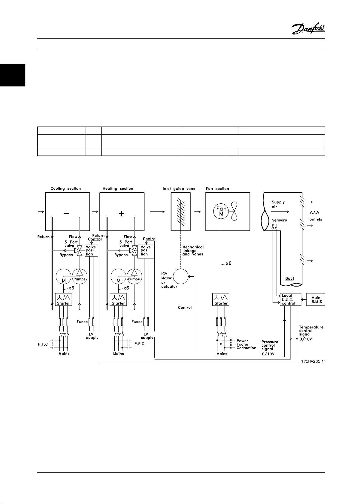
The example on the following page shows that a lot of extra equipment is not required when an adjustable frequency drive
is used. It is possible to calculate the cost of installing the two different systems. In the example on the following page, the
two systems can be established at roughly the same price.
2.7.10 Without an Adjustable Frequency Drive
D.D.C. = Direct Digital Control E.M.S. = Energy Management system
V.A.V. = Variable Air Volume
Sensor P = Pressure Sensor T = Temperature
Table 2.9 Abbreviations used in Figure 2.15 and Figure 2.16
Figure 2.15 Traditional Fan System
26 Danfoss A/S © Rev. 06/2014 All rights reserved. MG11BC22
Page 29
175HA206.11
Pump
Flow
Return
Supply
air
V.A.V
outlets
Duct
Mains
Pump
Return
Flow
Mains
Fan
Main
B.M.S
Local
D.D.C.
control
Sensors
Mains
Cooling section Heating section
Fan section
Pressure
control
0-10V
or
0/4-20mA
Control
temperature
0-10V
or
0/4-20mA
Control
temperature
0-10V
or
0/4-20mA
VLT
M
- +
VLT
M
M
P
T
VLT
x3 x3
x3
Introduction to VLT® HVAC D...
Design Guide
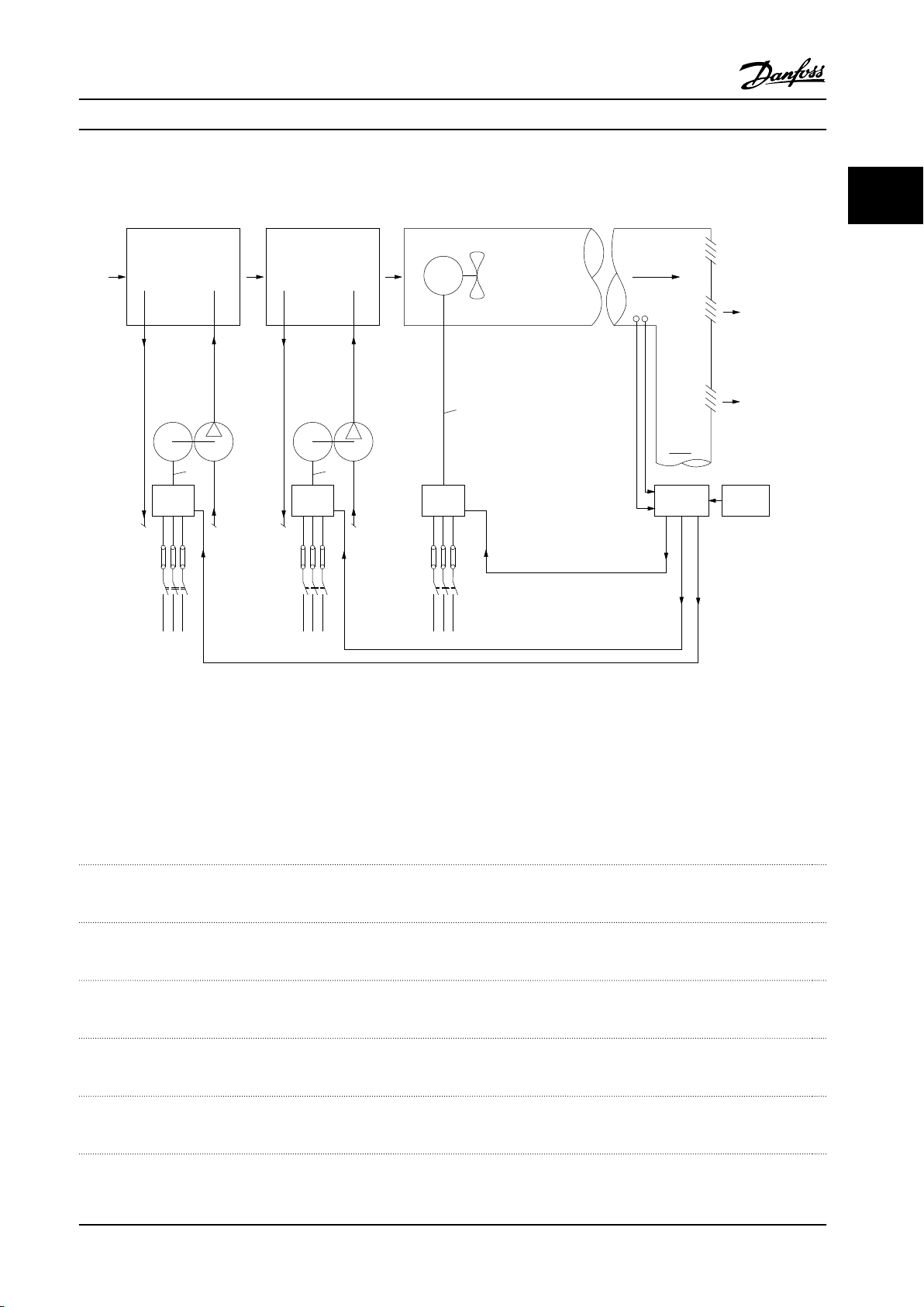
2.7.11 With an Adjustable Frequency Drive
2 2
Figure 2.16 Fan System Controlled by Adjustable Frequency Drives.
2.7.12
Application Examples
The following pages give typical examples of applications within HVAC.
For further information about a given application, ask a Danfoss supplier for an information sheet that gives a full
description of the application.
Variable Air Volume
Ask for The Drive to...Improving Variable Air Volume Ventilation Systems MN.60.A1.02
Constant Air Volume
Ask for The Drive to...Improving Constant Air Volume Ventilation Systems MN.60.B1.02
Cooling Tower Fan
Ask for The Drive to...Improving fan control on cooling towers MN.60.C1.02
Condenser pumps
Ask for The Drive to...Improving condenser water pumping systems MN.60.F1.02
Primary pumps
Ask for The Drive to...Improve your primary pumping in primary/secondary pumping systems MN.60.D1.02
Secondary pumps
Ask for The Drive to...Improve your secondary pumping in primary/secondary pumping systems MN.60.E1.02
MG11BC22 Danfoss A/S © Rev. 06/2014 All rights reserved. 27
Page 30
Frequency
converter
Frequency
converter
D1
D2
D3
Cooling coil
Heating coil
Filter
Pressure
signal
Supply fan
VAV boxes
Flow
Flow
Pressure
transmitter
Return fan
3
3
T
130BB455.10
Introduction to VLT® HVAC D... Design Guide
2.7.13 Variable Air Volume
22
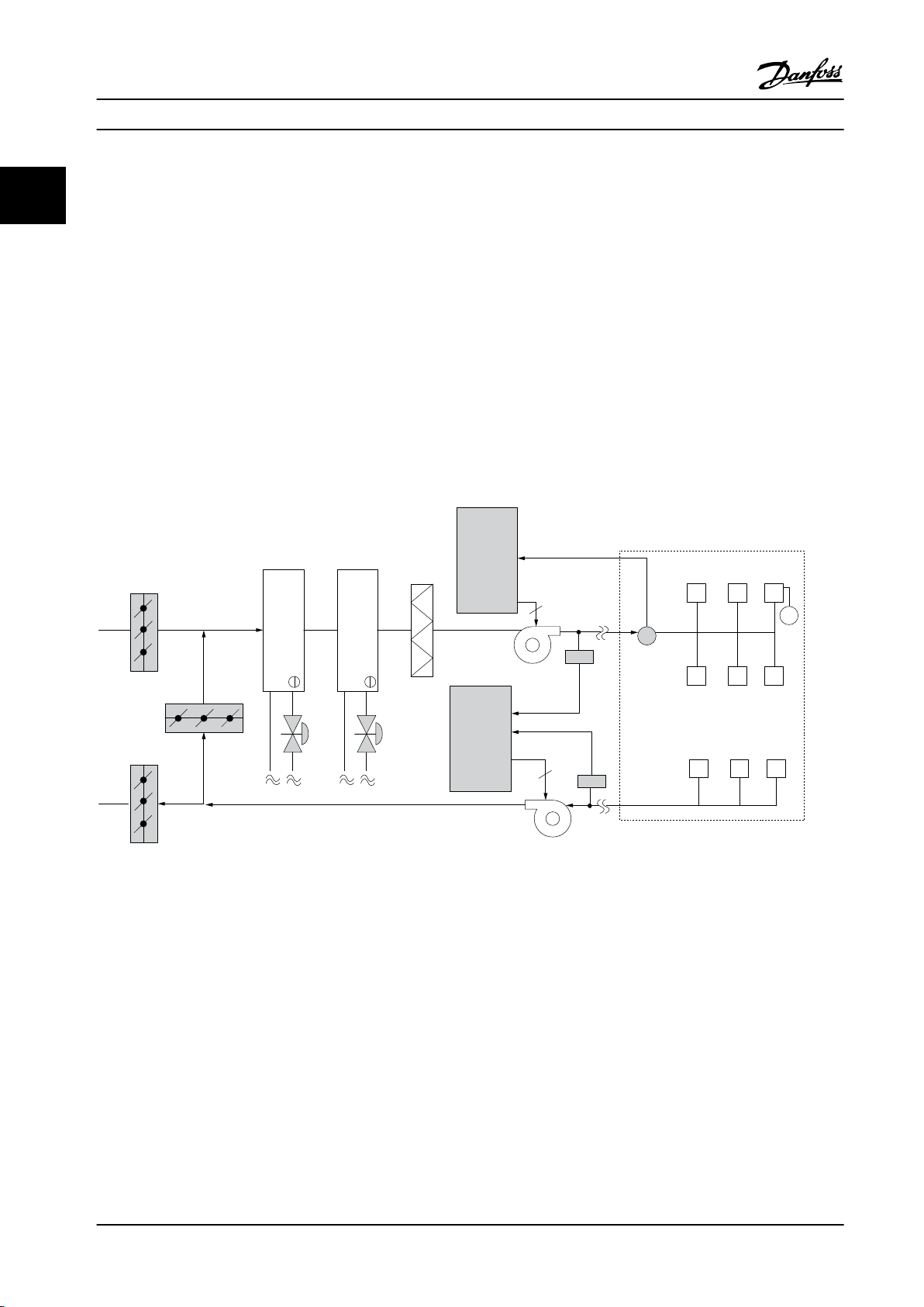
VAV or Variable Air Volume systems, are used to control both the ventilation and temperature to satisfy the requirements of
a building. Central VAV systems are considered to be the most energy efficient method to air condition buildings. By
designing central systems instead of distributed systems, greater efficiency can be obtained.
The efficiency comes from utilizing larger fans and larger chillers which have much higher efficiencies than small motors
and distributed air-cooled chillers. Savings are also a result of decreased maintenance requirements.
2.7.14 The VLT Solution
While dampers and IGVs work to maintain a constant pressure in the ductwork, a solution saves much more energy and
reduces the complexity of the installation. Instead of creating an artificial pressure drop or causing a decrease in fan
efficiency, the decreases the speed of the fan to provide the flow and pressure required by the system.
Centrifugal devices such as fans behave according to the centrifugal laws. This means the fans decrease the pressure and
flow they produce as their speed is reduced. Their power consumption is thereby significantly reduced.
The return fan is frequently controlled to maintain a fixed difference in airflow between the supply and return. The
advanced PID controller of the HVAC can be used to eliminate the need for additional controllers.
Figure 2.17 The VLT Solution
28 Danfoss A/S © Rev. 06/2014 All rights reserved. MG11BC22
Page 31
Frequency
converter
Frequency
converter
Pressure
signal
Cooling coil
Heating coil
D1
D2
D3
Filter
Pressure
transmitter
Supply fan
Return fan
Temperature
signal
Temperature
transmitter
130BB451.10
Introduction to VLT® HVAC D... Design Guide
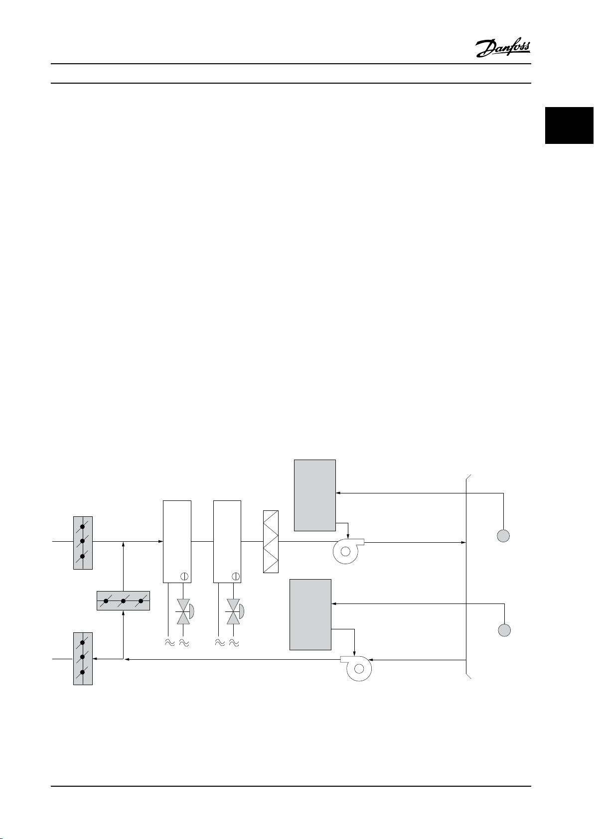
2.7.15 Constant Air Volume
CAV, or Constant Air Volume systems, are central ventilation systems usually used to supply large common zones with the
minimum amounts of fresh tempered air. They preceded VAV systems and therefore are found in older, multi-zoned
commercial buildings as well. These systems preheat amounts of fresh air utilizing Air Handling Units (AHUs) with a heating
coil, and many are also used to air condition buildings and have a cooling coil. Fan coil units are frequently used to assist in
the heating and cooling requirements in the individual zones.
2.7.16 The VLT Solution
With an adjustable frequency drive, significant energy savings can be obtained while maintaining decent control of the
building. Temperature sensors or CO2 sensors can be used as feedback signals to adjustable frequency drives. Whether
controlling temperature, air quality, or both, a CAV system can be controlled to operate based on actual building conditions.
As the number of people in the controlled area decreases, the need for fresh air decreases. The CO2 sensor detects lower
levels and decreases the supply fans speed. The return fan modulates to maintain a static pressure setpoint or fixed
difference between the supply and return air flows.
With temperature control (especially used in air conditioning systems), as the outside temperature varies and the number of
people in the controlled zone changes, different cooling requirements arise. As the temperature decreases below the
setpoint, the supply fan can decrease its speed. The return fan modulates to maintain a static pressure setpoint. By
decreasing the air flow, energy used to heat or cool the fresh air is also reduced, adding further savings.
Several features of the Danfoss HVAC dedicated adjustable frequency drive can be utilized to improve the performance of a
CAV system. One concern of controlling a ventilation system is poor air quality. The programmable minimum frequency can
be set to maintain a minimum amount of supply air, regardless of the feedback or reference signal. The adjustable
frequency drive also includes a 3-zone, 3-setpoint PID controller which allows monitoring of both temperature and air
quality. Even if the temperature requirement is satisfied, the adjustable frequency drive will maintain enough supply air to
satisfy the air quality sensor. The adjustable frequency drive is capable of monitoring and comparing two feedback signals
to control the return fan by maintaining a fixed differential air flow between the supply and return ducts as well.
2 2
Figure 2.18 The VLT Solution
MG11BC22 Danfoss A/S © Rev. 06/2014 All rights reserved. 29
Page 32
Introduction to VLT® HVAC D... Design Guide
2.7.17 Cooling Tower Fan
22
Cooling tower fans are used to cool condenser water in water-cooled chiller systems. Water-cooled chillers provide the most
efficient means of creating chilled water. They are as much as 20% more efficient than air-cooled chillers. Depending on
climate, cooling towers are often the most energy efficient method of cooling the condenser water from chillers.
They cool the condenser water by evaporation.
The condenser water is sprayed into the cooling tower, onto the cooling tower's “fill” to increase its surface area. The tower
fan blows air through the fill and sprayed water to aid in the evaporation. Evaporation removes energy from the water, thus
dropping its temperature. The cooled water collects in the cooling towers basin, where it is pumped back into the chiller's
condenser, and the cycle is then repeated.
2.7.18 The VLT Solution
With an adjustable frequency drive, the cooling towers fans can be set to the speed required to maintain the condenser
water temperature. The adjustable frequency drives can also be used to turn the fan on and off as needed.
Several features of the Danfoss HVAC dedicated adjustable frequency drive, the HVAC adjustable frequency drive can be
utilized to improve the performance of a cooling tower fans application. As the cooling tower fans drop below a certain
speed, the effect the fan has on cooling the water becomes insignificant. Also, when utilizing a gear box to frequency
control the tower fan, a minimum speed of 40–50% may be required.
The customer programmable minimum frequency setting is available to maintain this minimum frequency even as the
feedback or speed reference calls for lower speeds.
Also as a standard feature, program the adjustable frequency drive to enter a “sleep” mode and stop the fan until a higher
speed is required. Additionally, some cooling tower fans have undesirable frequencies that may cause vibrations. These
frequencies can easily be avoided by programming the bypass frequency ranges in the adjustable frequency drive.
30 Danfoss A/S © Rev. 06/2014 All rights reserved. MG11BC22
Page 33
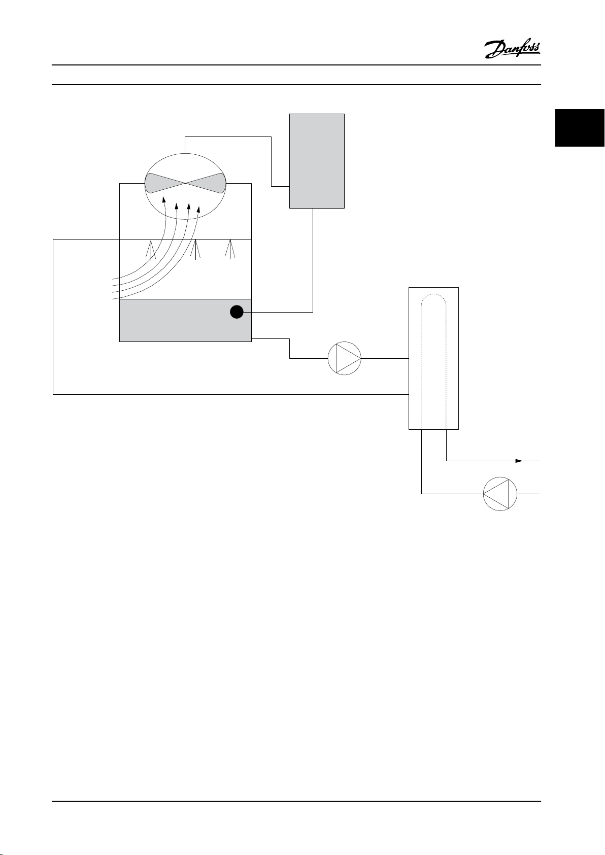
Frequency
converter
Water Inlet
Water Outlet
CHILLER
Temperature
Sensor
BASIN
Conderser
Water pump
Supply
130BB453.10
Introduction to VLT® HVAC D... Design Guide
2 2
Figure 2.19 The VLT Solution
MG11BC22 Danfoss A/S © Rev. 06/2014 All rights reserved. 31
Page 34
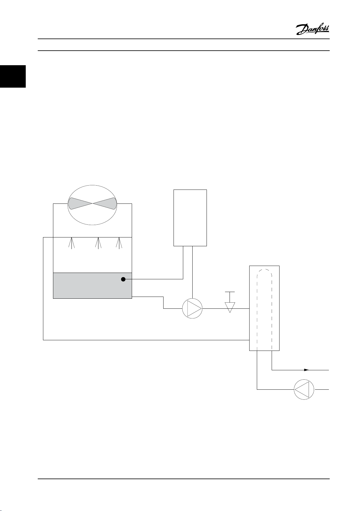
Frequency
converter
Water
Inlet
Water
Outlet
BASIN
Flow or pressure sensor
Condenser
Water pump
Throttling
valve
Supply
CHILLER
130BB452.10
Introduction to VLT® HVAC D... Design Guide
2.7.19 Condenser Pumps
22
Condenser water pumps are primarily used to circulate water through the condenser section of water cooled chillers and
their associated cooling tower. The condenser water absorbs the heat from the chiller's condenser section and releases it
into the atmosphere in the cooling tower. These systems are used to provide the most efficient means of creating chilled
water, and they are as much as 20% more efficient than air cooled chillers.
2.7.20 The VLT Solution
Adjustable frequency drives can be added to condenser water pumps instead of balancing the pumps with a throttling
valve or trimming the pump impeller.
Using an adjustable frequency drive instead of a throttling valve simply saves the energy that would have been absorbed
by the valve. This can amount to savings of 15–20% or more. Trimming the pump impeller is irreversible, thus if the
conditions change and higher flow is required the impeller must be replaced.
Figure 2.20 The VLT Solution
32 Danfoss A/S © Rev. 06/2014 All rights reserved. MG11BC22
Page 35
Introduction to VLT® HVAC D... Design Guide
2.7.21 Primary Pumps
Primary pumps in a primary/secondary pumping system can be used to maintain a constant flow through devices that
encounter operation or control difficulties when exposed to variable flow. The primary/secondary pumping technique
decouples the “primary” production loop from the “secondary” distribution loop. This allows devices such as chillers to
obtain constant design flow and operate properly, while allowing the rest of the system to vary in flow.
As the evaporator flow rate decreases in a chiller, the chilled water begins to become overly chilled. As this happens, the
chiller attempts to decrease its cooling capacity. If the flow rate drops far enough, or too quickly, the chiller cannot shed its
load sufficiently and the chiller’s low evaporator temperature safety trips the chiller, requiring a manual reset. This situation
is common in large installations especially when two or more chillers are installed in parallel, if primary/secondary pumping
is not utilized.
2.7.22 The VLT Solution
Depending on the size of the system and the size of the primary loop, the energy consumption of the primary loop can
become substantial.
An adjustable frequency drive can be added to the primary system, to replace the throttling valve and/or trimming of the
impellers, leading to reduced operating expenses. Two control methods are common:
The first method uses a flow meter. Because the desired flow rate is known and constant, a flow meter installed at the
discharge of each chiller can be used to control the pump directly. Using the built-in PID controller, the adjustable
frequency drive always maintains the appropriate flow rate, even compensating for the changing resistance in the primary
piping loop as chillers and their pumps are staged on and off.
2 2
The other method is local speed determination. The operator simply decreases the output frequency until the design flow
rate is achieved.
Using an adjustable frequency drive to decrease the pump speed is very similar to trimming the pump impeller, except it
does not require any labor and the pump efficiency remains higher. The balancing contractor simply decreases the speed of
the pump until the proper flow rate is achieved and leaves the speed fixed. The pump operates at this speed any time the
chiller is staged on. Because the primary loop does not have control valves or other devices that can cause the system curve
to change, and the variance due to staging pumps and chillers on and off is usually small, this fixed speed remains
appropriate. In the event the flow rate needs to be increased later in the systems life, the adjustable frequency drive can
simply increase the pump speed instead of requiring a new pump impeller.
MG11BC22 Danfoss A/S © Rev. 06/2014 All rights reserved. 33
Page 36
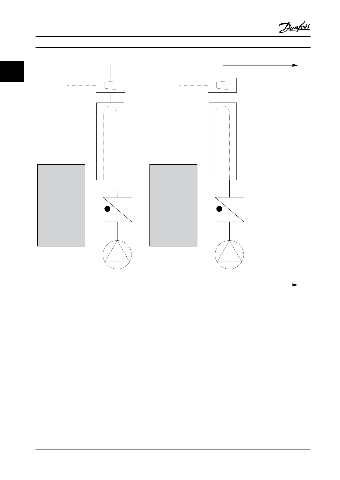
Frequency
converter
Frequency
converter
CHILLER
CHILLER
Flowmeter
Flowmeter
F F
130BB456.10
Introduction to VLT® HVAC D... Design Guide
22
Figure 2.21 The VLT Solution
34 Danfoss A/S © Rev. 06/2014 All rights reserved. MG11BC22
Page 37
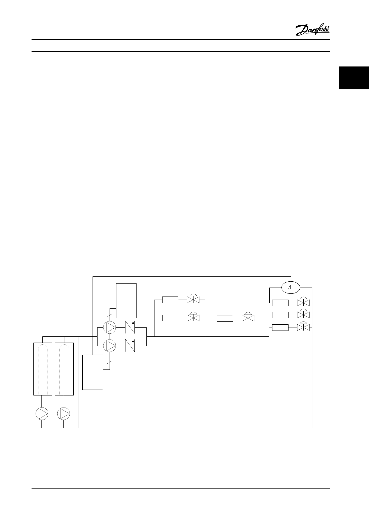
Frequency
converter
Frequency
converter
CHILLER
CHILLER
3
3
P
130BB454.10
Introduction to VLT® HVAC D... Design Guide
2.7.23 Secondary Pumps
Secondary pumps in a primary/secondary chilled water pumping system are used to distribute the chilled water to the loads
from the primary production loop. The primary/secondary pumping system is used to hydraulically de-couple one piping
loop from another. In this case, the primary pump is used to maintain a constant flow through the chillers while allowing
the secondary pumps to vary in flow, increase control and save energy.
If the primary/secondary design concept is not used and a variable volume system is designed, the chiller cannot shed its
load properly when the flow rate drops far enough or too quickly. The chiller’s low evaporator temperature safety then trips
the chiller, requiring a manual reset. This situation is common in large installations, especially when two or more chillers are
installed in parallel.
2.7.24 The VLT Solution
While the primary-secondary system with two-way valves improves energy savings and eases system control problems, the
true energy savings and control potential is realized by adding adjustable frequency drives.
With the proper sensor location, the addition of adjustable frequency drives allows the pumps to vary their speed to follow
the system curve instead of the pump curve.
This results in the elimination of wasted energy and eliminates most of the over-pressurization two-way valves can be
subjected to.
As the monitored loads are reached, the two-way valves close down. This increases the differential pressure measured
across the load and two-way valve. As this differential pressure starts to rise, the pump is slowed to maintain the control
head also called setpoint value. This setpoint value is calculated by summing up the pressure drop of the load and two-way
valve under design conditions.
2 2
Note that when running multiple pumps in parallel, they must run at the same speed to maximize energy savings, either
with individual dedicated drives or one running multiple pumps in parallel.
Figure 2.22 The VLT Solution
MG11BC22 Danfoss A/S © Rev. 06/2014 All rights reserved. 35
Page 38
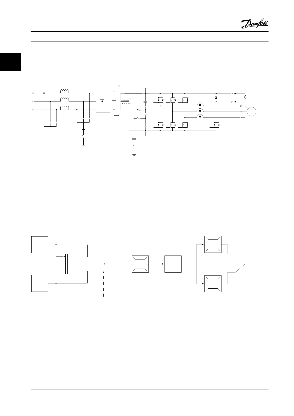
Inrush
R inr
Load sharing -
Load sharing +
LC Filter (5A)
LC Filter +
(5A)
Brake
Resistor
130BA193.14
M
L2 92
L1 91
L3 93
89(+)
88(-)
R+
82
R81
U 96
V 97
W 98
P 14-50 R Filter
130BB153.10
100%
0%
-100%
100%
P 3-13
Reference
site
Local
reference
scaled to
RPM or Hz
Auto mode
Hand mode
LCP Hand on,
o and auto
on keys
Linked to hand/auto
Local
Remote
Reference
Ramp
P 4-10
Motor speed
direction
To motor
control
Reference
handling
Remote
reference
P 4-13
Motor speed
high limit [RPM]
P 4-14
Motor speed
high limit [Hz]
P 4-11
Motor speed
low limit [RPM]
P 4-12
Motor speed
low limit [Hz]
P 3-4* Ramp 1
P 3-5* Ramp 2
Introduction to VLT® HVAC D...
Design Guide
2.8 Control Structures
22
2.8.1 Control Principle
Figure 2.23 Control Structures
The adjustable frequency drive is a high-performance unit for demanding applications. It can handle various kinds of motor
control principles such as U/f special motor mode and VVC
plus
and can handle normal squirrel cage asynchronous motors.
Short circuit behavior on this adjustable frequency drive depends on the three current transducers in the motor phases.
Select between open-loop and closed-loop in 1-00 Configuration Mode.
Control Structure Open-loop
2.8.2
Figure 2.24 Open-loop Structure
In the configuration shown in Figure 2.24, 1-00 Configuration Mode is set to [0] Open-loop. The resulting reference from the
reference handling system or the local reference is received and fed through the ramp limitation and speed limitation
before being sent to the motor control.
The output from the motor control is then limited by the maximum frequency limit.
36 Danfoss A/S © Rev. 06/2014 All rights reserved. MG11BC22
Page 39
Introduction to VLT® HVAC D... Design Guide
2.8.3 PM/EC+ Motor Control
The Danfoss EC+ concept provides the possibility for using
high efficient PM motors in IEC standard enclosure types
operated by Danfoss adjustable frequency drives.
The commissioning procedure is comparable to the
existing one for asynchronous (induction) motors by
utilizing the Danfoss VVC
Customer advantages:
Free choice of motor technology (permanent
•
magnet or induction motor)
Installation and operation as known for induction
•
motors
Manufacturer independent when choosing system
•
components (e.g., motors)
Best system efficiency by choosing best
•
components
Possible retrofit of existing installations
•
Power range: 1.5–30 hp [1.1–22 kW]
•
Current limitations:
Currently only supported up to 30 hp [22 kW]
•
Currently limited to non-salient type PM motors
•
LC filters not supported together with PM motors
•
Over Voltage Control algorithm is not supported
•
with PM motors
Kinetic backup algorithm is not supported with
•
PM motors
AMA algorithm is not supported with PM motors
•
No missing motor phase detection
•
No stall detection
•
No ETR function
•
plus
PM control strategy.
Sizing of Adjustable Frequency Drive
2.8.4
and PM motor
The low motor inductances of PM motors can cause
current ripples in the adjustable frequency drive.
To select the right adjustable frequency drive for a given
PM motor, ensure that:
The adjustable frequency drive can deliver the
•
required power and current in all operating
conditions.
The power rating of the adjustable frequency
•
drive is equal to or higher than the power rating
of the motor.
Size the adjustable frequency drive for a constant
•
100% operating load with sufficient safety
margin.
The current (A) and the typical power rating (kW) for a PM
motor can be found in chapter 9.1 Line Power Supply Tables
for different voltages.
2 2
MG11BC22 Danfoss A/S © Rev. 06/2014 All rights reserved. 37
Page 40
Introduction to VLT® HVAC D...
Design Guide
Sizing examples for nominal power rating
22
Example 1
•
•
PM motor size: 1.5 kW / 2.9 A
Line power: 3 x 400 V
Adjustable
Frequency Drive
P1K1 1.1 1.5 3.0 3.3 2.7 3.0
P1K5 1.5 2.0 4.1 4.5 3.4 3.7
Table 2.10 Sizing Data for 1.5 and 2 hp [1.1 and 1.5 kW] Adjustable Frequency Drives
Typical [kW] Typical [hp] at
460 V
Continuous
[A]
(3x380–440 V)
Intermitted
[A]
(3x380–440 V)
Continuous
[A]
(3x441–480 V)
Intermitted
[A]
(3x441–480 V)
The current rating of the PM motor (2.9 A) matches the current rating of both the 1.5 hp [1.1 kW] adjustable frequency
drive (3 A @ 400 V) and the 2 hp [1.5 kW] adjustable frequency drive (4.1 A @ 400 V). However, since the power rating of
the motor is 2 hp [1.5 kW], the 2 hp [1.5 kW] adjustable frequency drive is the correct choice.
Power 2 hp [1.5 kW] 2 hp [1.5 kW]
Current 2.9 A 4.1 A @ 400V
Table 2.11 Correctly Sized Adjustable Frequency Drive
Motor Adjustable Frequency Drive 2 hp [1.5 kW]
Example 2
PM motor size: 7.5 hp [5.5 kW] / 12.5 A
•
Line power: 3 x 400 V
•
Adjustable
Frequency Drive
P4K0 4.0 5.0 10.0 11.0 8.2 9.0
P5K5 5.5 7.5 13.0 14.3 11.0 12.1
Typical [kW] Typical [hp] at
460 V
Continuous
[A]
(3x380–440 V)
Intermitted
[A]
(3x380–440 V)
Continuous
[A]
(3x441–480 V)
Intermitted
[A]
(3x441–480 V)
Table 2.12 Sizing Data for 5 and 7.5 hp [4.0 and 5.5 kW] Adjustable Frequency Drives
The current rating of the PM motor (12.5 A) matches the current rating of the 7.5 hp [5.5 kW] adjustable frequency drive
(13 A @ 400 V), not the current rating of the 5 hp [4.0 kW] adjustable frequency drive (10 A @ 400 V). Since the power
rating of the motor is 7.5 hp [5.5 kW], the 7.5 hp [5.5 kW] adjustable frequency drive is the correct choice.
Power 7.5 hp [5.5 kW] 7.5 hp [5.5 kW]
Current 12.5 A 13 A @ 400 V
Table 2.13 Correctly Sized Adjustable Frequency Drive
38 Danfoss A/S © Rev. 06/2014 All rights reserved. MG11BC22
Motor Adjustable Frequency Drive 7.5 hp [5.5 kW]
Page 41
130BP046.10
Hand
on
O
Auto
on
Reset
Introduction to VLT® HVAC D... Design Guide
2.8.5 Local (Hand On) and Remote (Auto
On) Control
The adjustable frequency drive can be operated manually
via the local control panel (LCP) or remotely via
analog/digital inputs or serial bus.
If allowed in 0-40 [Hand on] Key on LCP, 0-41 [Off] Key on
LCP, 0-42 [Auto on] Key on LCP, and 0-43 [Reset] Key on LCP,
it is possible to start and stop the adjustable frequency
drive by LCP using the [Hand On] and [Off] keys. Alarms
can be reset via the [Reset] key. After pressing [Hand On],
the adjustable frequency drive goes into Hand Mode and
follows (as default) the local reference set by using
[▲] and [▼].
After pressing [Auto On], the adjustable frequency drive
goes into Auto mode and follows (as default) the remote
reference. In this mode, it is possible to control the
adjustable frequency drive via the digital inputs and
various serial interfaces (RS-485, USB, or an optional serial
communication bus). See more about starting, stopping,
changing ramps and parameter set-ups, etc.,in parameter
group 5-1* Digital Inputs or parameter group 8-5* Serial
Communication.
Local reference forces the configuration mode to openloop, independent on the setting of 1-00 Configuration
Mode.
Local reference is restored at power-down.
2.8.6 Control Structure Closed-loop
The internal controller allows the adjustable frequency
drive to become an integral part of the controlled system.
The adjustable frequency drive receives a feedback signal
from a sensor in the system. It then compares this
feedback to a setpoint reference value and determines the
error, if any, between these two signals. It then adjusts the
speed of the motor to correct this error.
For example, consider a pump application where the
speed of a pump is to be controlled so that the static
pressure in a pipe is constant. The desired static pressure
value is supplied to the adjustable frequency drive as the
setpoint reference. A static pressure sensor measures the
actual static pressure in the pipe and supplies this to the
adjustable frequency drive as a feedback signal. If the
feedback signal is greater than the setpoint reference, the
adjustable frequency drive slows down to reduce the
pressure. In a similar way, if the pipe pressure is lower than
the setpoint reference, the adjustable frequency drive
automatically speed up to increase the pressure provided
by the pump.
2 2
Figure 2.25 Operation Keys
Hand Off
Auto
LCP Keys
Hand Linked to Hand/
Hand ⇒ Off
Auto Linked to Hand/
Auto ⇒ Off
All keys Local Local
All keys Remote Remote
Table 2.14 Conditions for Either Local or Remote Reference
3-13 Reference Site Active Reference
Local
Auto
Linked to Hand/
Auto
Auto
Linked to Hand/
Auto
Local
Remote
Remote
Table 2.14 shows under which conditions either the local
reference or the remote reference is active. One of them is
always active, but both cannot be active at the same time.
MG11BC22 Danfoss A/S © Rev. 06/2014 All rights reserved. 39
Page 42
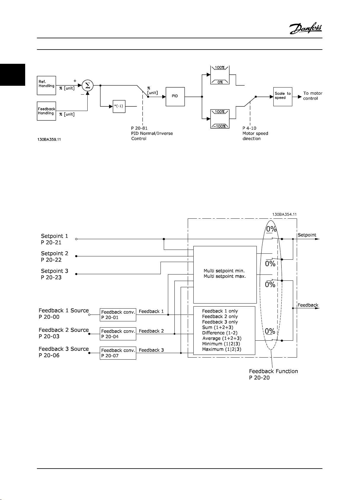
Introduction to VLT® HVAC D... Design Guide
22
Figure 2.26 Block Diagram of Closed-loop Controller
While the default values for the adjustable frequency drive’s closed-loop controller often provides satisfactory performance,
the control of the system can often be optimized by adjusting some of the closed-loop controller’s parameters. It is also
possible to autotune the PI constants.
Feedback Handling
2.8.7
Figure 2.27 Block Diagram of Feedback Signal Processing
40 Danfoss A/S © Rev. 06/2014 All rights reserved. MG11BC22
Page 43
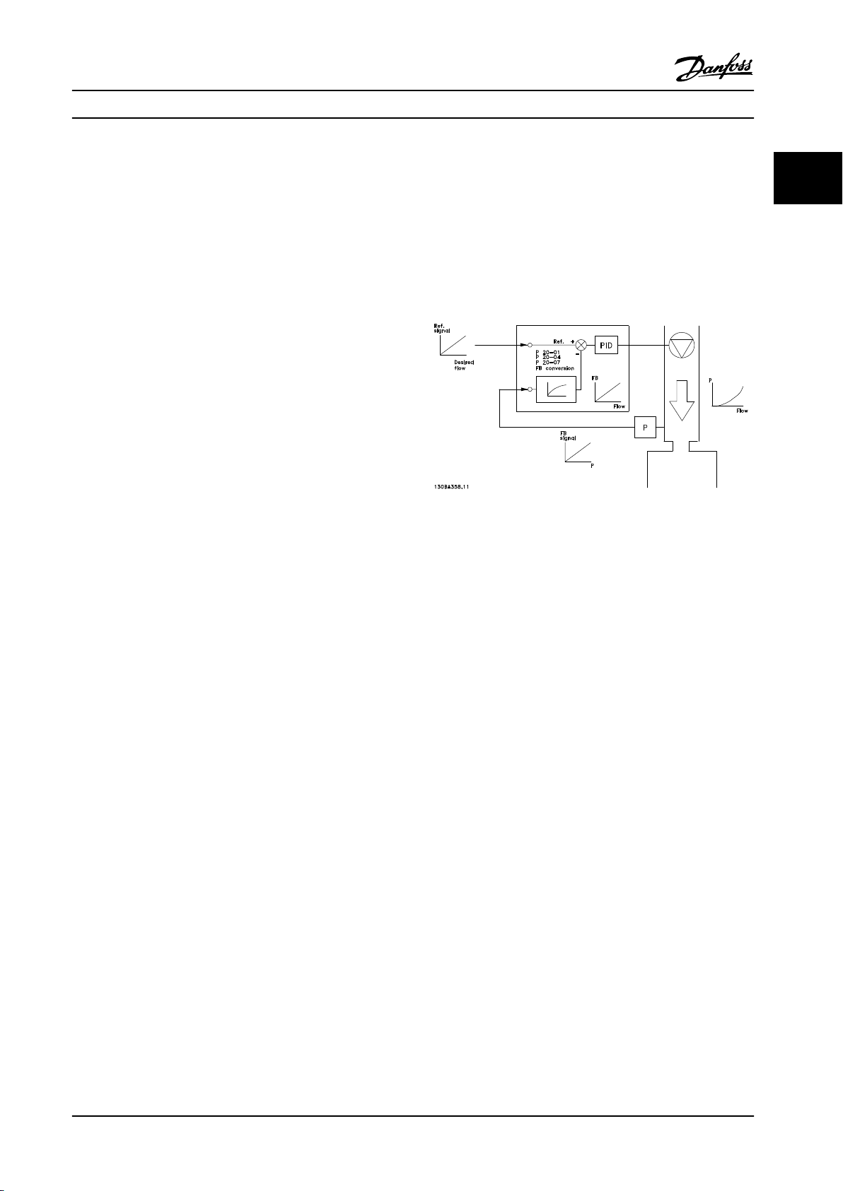
Introduction to VLT® HVAC D... Design Guide
Feedback handling can be configured to work with
applications requiring advanced control, such as multiple
setpoints and multiple feedbacks. Three types of control
are common.
Single Zone, Single Setpoint
Single Zone, Single Setpoint is a basic configuration.
Setpoint 1 is added to any other reference (if any, see
Reference Handling) and the feedback signal is selected
using 20-20 Feedback Function.
Multi-zone, Single Setpoint
Multi-zone, Single Setpoint uses two or three feedback
sensors, but only one setpoint. Feedback can be added,
subtracted (only feedback 1 and 2) or averaged. In
addition, the maximum or minimum value may be used.
Setpoint 1 is used exclusively in this configuration.
If [5] Multi Setpoint Min is selected, the setpoint/feedback
pair with the largest difference controls the speed of the
adjustable frequency drive. [6] Multi Setpoint Max attempts
to keep all zones at or below their respective setpoints,
while [5] Multi Setpoint Min attempts to keep all zones at
or above their respective setpoints.
Example
A two-zone two setpoint application Zone 1 setpoint is
15 bar and the feedback is 5.5 bar. Zone 2 setpoint is
4.4 bar and the feedback is 4.6 bar. If [14] Multi Setpoint
Max is selected, Zone 1’s setpoint and feedback are sent to
the PID controller, since this has the smaller difference
(feedback is higher than setpoint, resulting in a negative
difference). If [13] Multi Setpoint Min is selected, Zone 2’s
setpoint and feedback is sent to the PID controller, since
this has the larger difference (feedback is lower than
setpoint, resulting in a positive difference).
Feedback Conversion
2.8.8
In some applications, it may be useful to convert the
feedback signal. One example of this is using a pressure
signal to provide flow feedback. Since the square root of
pressure is proportional to flow, the square root of the
pressure signal yields a value proportional to the flow. This
is shown in Figure 2.28.
Figure 2.28 Feedback Conversion
2 2
MG11BC22 Danfoss A/S © Rev. 06/2014 All rights reserved. 41
Page 44
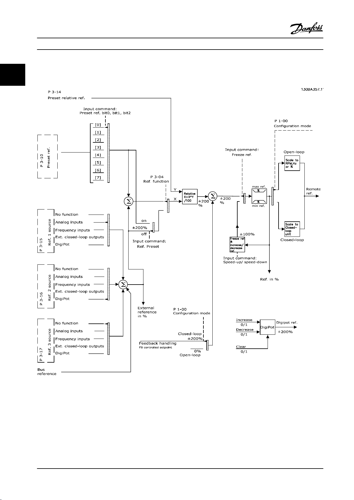
Introduction to VLT® HVAC D... Design Guide
2.8.9 Reference Handling
22
Details for Open-loop and Closed-loop operation
Figure 2.29 Block Diagram Showing Remote Reference
42 Danfoss A/S © Rev. 06/2014 All rights reserved. MG11BC22
Page 45
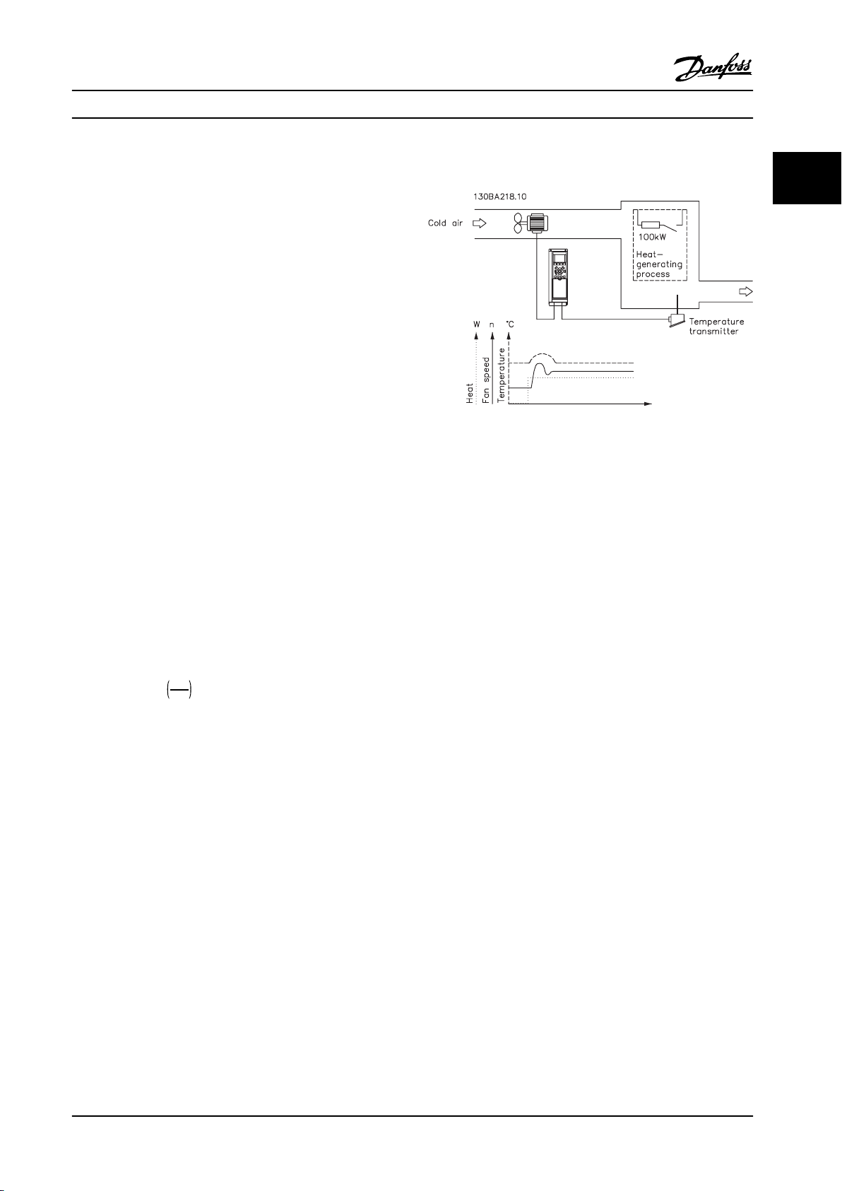
Introduction to VLT® HVAC D... Design Guide
The remote reference is comprised of:
Preset references.
•
External references (analog inputs, pulse
•
frequency inputs, digital potentiometer inputs
and serial communication bus references).
The preset relative reference.
•
Feedback controlled setpoint.
•
Up to eight preset references can be programmed in the
adjustable frequency drive. The active preset reference can
be selected using digital inputs or the serial communications bus. The reference can also be supplied externally,
most commonly from an analog input. This external source
is selected by one of the three Reference Source
parameters (3-15 Reference 1 Source, 3-16 Reference 2 Source
and 3-17 Reference 3 Source). Digipot is a digital potentiometer. This is also commonly called a Speed Up/Slow
Control or a Floating Point Control. To set it up, one digital
input is programmed to increase the reference, while
another digital input is programmed to decrease the
reference. A third digital input can be used to reset the
digipot reference. All reference resources and the bus
reference are added to produce the total external
reference. The external reference, the preset reference or
the sum of the two can be selected to be the active
reference. Finally, this reference can be scaled by using
3-14 Preset Relative Reference.
2.8.10
In a ventilation system, the temperature is to be
maintained at a constant value. The desired temperature is
set between 23–95 °F [-5–+35 °C] using a 0–10 V potentiometer. Because this is a cooling application, if the
temperature is above the setpoint value, the speed of the
fan must be increased to provide more cooling air flow.
The temperature sensor has a range of 14–104 °F
[-10–+40 °C] and uses a two-wire transmitter to provide a
4–20 mA signal. The output frequency range of the
adjustable frequency drive is 10 to 50 Hz.
Example of Closed-loop PID Control
Figure 2.30 Closed-loop Control for a Ventilation System
2 2
The scaled reference is calculated as follows:
Reference
= X + X ×
Where X is the external reference, the preset reference or
the sum of these and Y is 3-14 Preset Relative Reference in
[%].
If Y, 3-14 Preset Relative Reference is set to 0%, the
reference is affected by the scaling.
Y
100
1. Start/Stop via switch connected between
terminals 12 (+24 V) and 18.
2. Temperature reference via a potentiometer
(23–95 °F [-5–+35 °C], 0 to 10 V) connected to
terminals 50 (+10 V), 53 (input) and 55 (common).
3. Temperature feedback via transmitter (14–104 °F
[-10–+40 °C], 4–20 mA) connected to terminal 54.
Switch S202 behind the LCP set to ON (current
input).
MG11BC22 Danfoss A/S © Rev. 06/2014 All rights reserved. 43
Page 46
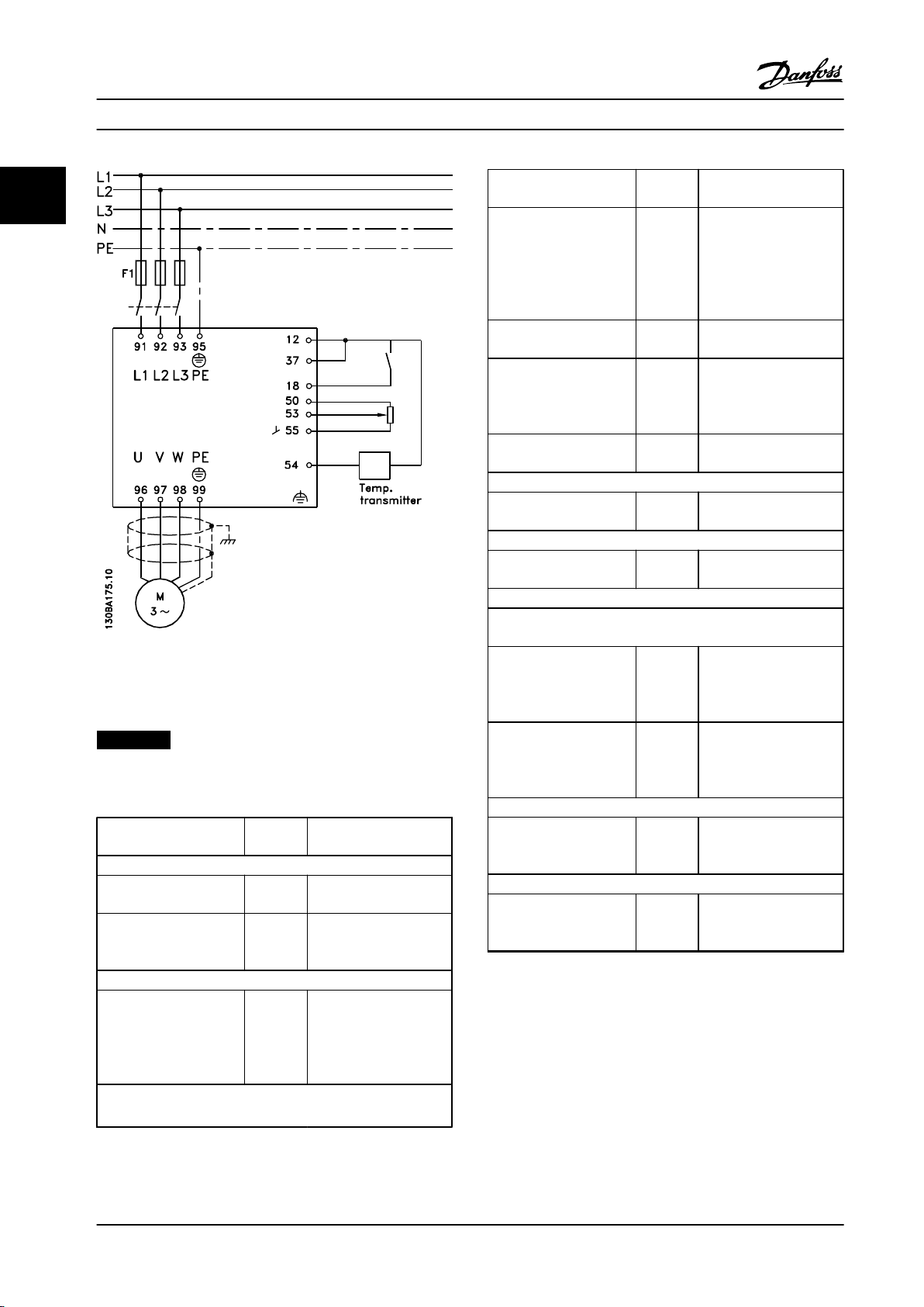
Introduction to VLT® HVAC D... Design Guide
Function Para--
22
Check that the ramp
settings are within
capabilities of the
adjustable frequency drive
and allowed application
operating specifications.
Prohibit the motor from
reversing (if necessary).
Set acceptable limits for
the motor speed.
Switch from open-loop to
closed-loop.
4) Configure the feedback to the PID controller.
Select the appropriate
reference/feedback unit.
5) Configure the setpoint reference for the PID controller.
Set acceptable limits for
the setpoint reference.
Select current or voltage by switches S201 / S202.
6) Scale the analog inputs used for setpoint reference and
Figure 2.31 Example of Closed-loop PID Control
2.8.11
Programming Order
NOTICE!
In this example, it is assumed that an induction motor is
used, i.e., that 1-10 Motor Construction = [0] Asynchron.
Function Para--
meter
1) Make sure the motor runs properly. Do the following:
Set the motor parameters
using nameplate data.
Run Automatic Motor
Adaptation.
2) Check that the motor is running in the right direction.
Run Motor Rotation
Check.
3) Make sure the adjustable frequency drive limits are set to safe
values.
1-2* As specified by motor
1-29
1-28 If the motor runs in the
Setting
nameplate
[1] Enable complete AMA
and then run the AMA
function
wrong direction, remove
power temporarily and
reverse two of the motor
phases
feedback.
Scale Analog Input 53 for
the pressure range of the
potentiometer (0–10 Bar,
0–10 V).
Scale Analog Input 54 for
pressure sensor (0–10 Bar,
4–20 mA).
7) Tune the PID controller parameters.
Adjust the adjustable
frequency drive’s closedloop controller, if needed.
8) Save to finish.
Save the parameter
settings to the LCP for
safekeeping.
Table 2.15 Programming Order
meter
3-41
3-42
4-10
4-12
4-14
4-19
1-00
20-12
20-13
20-14
6-10
6-11
6-14
6-15
6-22
6-23
6-24
6-25
20-93
20-94
0-50
Setting
60 s
60 s
Depends on motor/load
size!
Also active in hand
mode.
[0] Clockwise
10 Hz, Motor min speed
50 Hz, Motor max speed
50 Hz, Drive max output
frequency
[3] Closed-loop
[71] Bar
0 Bar
10 Bar
0 V
10 V (default)
0 Bar
10 Bar
4 mA
20 mA (default)
0 Bar
10 Bar
See Optimization of the
PID Controller, below
[1] All to LCP
44 Danfoss A/S © Rev. 06/2014 All rights reserved. MG11BC22
Page 47
Introduction to VLT® HVAC D... Design Guide
2.8.12 Tuning the Adjustable Frequency
Drive Closed-loop Controller
Once the adjustable frequency drive's closed-loop
controller has been set up, the performance of the
controller should be tested. In many cases, its performance
may be acceptable using the default values of 20-93 PID
Proportional Gain and 20-94 PID Integral Time. However, in
some cases it may be helpful to optimize these parameter
values to provide faster system response while still
controlling speed overshoot.
2.8.13 Manual PID Adjustment
1. Start the motor.
2.
Set 20-93 PID Proportional Gain to 0.3 and
increase it until the feedback signal begins to
oscillate. If necessary, start and stop the
adjustable frequency drive or make step changes
in the setpoint reference to attempt to cause
oscillation. Next reduce the PID proportional gain
until the feedback signal stabilizes. Then reduce
the proportional gain by 40–60%.
3.
Set 20-94 PID Integral Time to 20 s and reduce it
until the feedback signal begins to oscillate. If
necessary, start and stop the adjustable frequency
drive or make step changes in the setpoint
reference to attempt to cause oscillation. Next,
increase the PID integral time until the feedback
signal stabilizes. Then increase of the integral
time by 15–50%.
4.
20-95 PID Differentiation Time should only be used
for very fast-acting systems. The typical value is
25% of 20-94 PID Integral Time. The differential
function should only be used when the setting of
the proportional gain and the integral time has
been fully optimized. Make sure that oscillations
of the feedback signal are sufficiently dampened
by the low-pass filter for the feedback signal
(parameters 6-16, 6-26, 5-54 or 5-59 as required).
2 2
MG11BC22 Danfoss A/S © Rev. 06/2014 All rights reserved. 45
Page 48
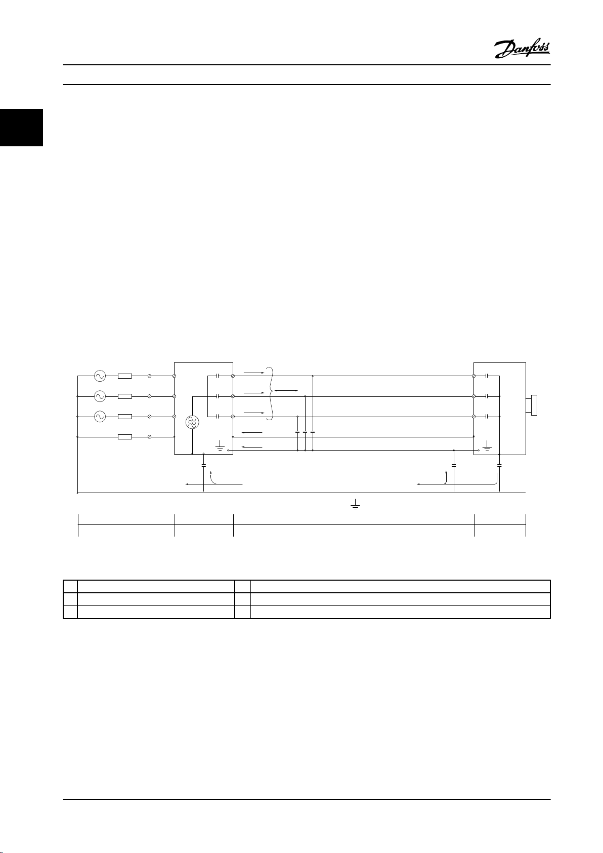
1
2
z
z
z
L1
L2
L3
PE
U
V
W
C
S
I
2
I
1
I
3
I
4
C
S
C
S
C
S
C
S
I
4
C
S
z
PE
3
4
5
6
175ZA062.12
Introduction to VLT® HVAC D...
Design Guide
2.9 General Aspects of EMC
22
Electrical interference is usually conducted at frequencies in the range 150 kHz to 30 MHz. Airborne interference from the
adjustable frequency drive system in the range 30 MHz to 1 GHz is generated from the inverter, motor cable, and the
motor.
As shown in Figure 2.32, capacitance in the motor cable coupled with a high dU/dt from the motor voltage generate
leakage currents.
The use of a shielded motor cable increases the leakage current (see Figure 2.32) because shielded cables have higher
capacitance to ground than non-shielded cables. If the leakage current is not filtered, it causes greater interference on the
line power in the radio frequency range below approximately 5 MHz. Since the leakage current (I1) is carried back to the
unit through the shield (I3), there is in principle only a small electro-magnetic field (I4) from the shielded motor cable
according to Figure 2.32.
The shield reduces the radiated interference, but increases the low-frequency interference in the line power supply. Connect
the motor cable shield to the adjustable frequency drive enclosure as well as on the motor enclosure. This is best done by
using integrated shield clamps so as to avoid twisted shield ends (pigtails) Pigtails increase the shield impedance at higher
frequencies, which reduces the shield effect and increases the leakage current (I4).
If a shielded cable is used for relay, control cable, signal interface and brake, mount the shield on the enclosure at both
ends. In some situations, however, it is necessary to break the shield to avoid current loops.
Figure 2.32 Situation that Generates Leakage Currents
1 Ground wire 4 Adjustable frequency drive
2 Shield 5 Shielded motor cable
3 AC line power supply 6 Motor
Table 2.16 Legend to Figure 2.32
If the shield is to be placed on a mounting plate for the adjustable frequency drive, the mounting plate must be made of
metal, to convey the shield currents back to the unit. Moreover, ensure good electrical contact from the mounting plate
through the mounting screws to the adjustable frequency driver chassis.
When non-shielded cables are used, some emission requirements are not complied with, although most immunity
requirements are observed.
46 Danfoss A/S © Rev. 06/2014 All rights reserved. MG11BC22
Page 49
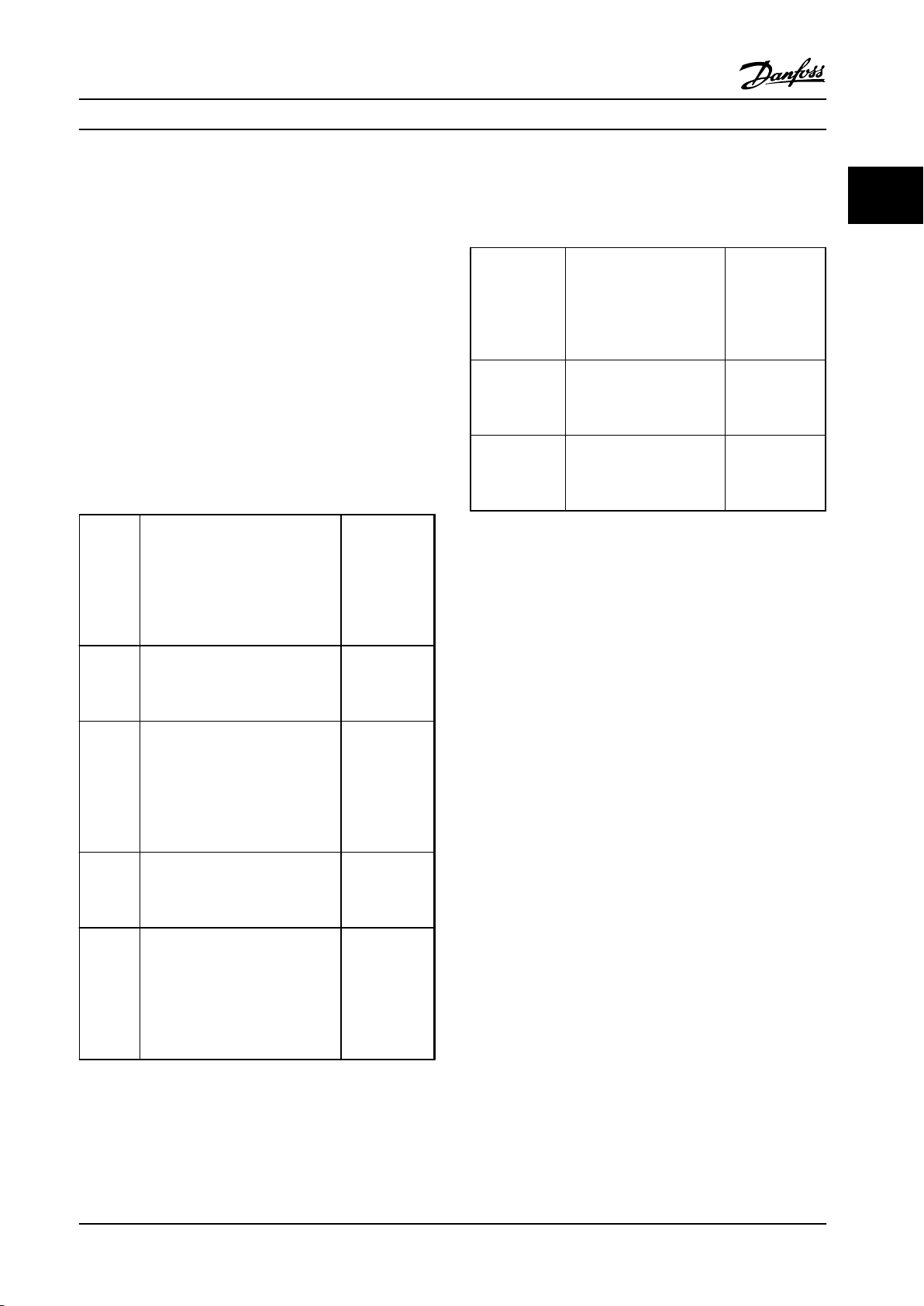
Introduction to VLT® HVAC D... Design Guide
To reduce the interference level from the entire system
(unit+installation), make motor and brake cables as short
as possible. Avoid placing cables with a sensitive signal
level alongside motor and brake cables. Radio interference
higher than 50 MHz (airborne) is especially generated by
the control electronics. See for more information on EMC.
2.9.1 Emission Requirements
According to the EMC product standard for adjustable
speed adjustable frequency drives EN/IEC 61800-3:2004,
the EMC requirements depend on the intended use of the
adjustable frequency drive. Four categories are defined in
the EMC product standard. The definitions of the four
categories together with the requirements for line power
supply voltage conducted emissions are given in
Table 2.17.
Conducted
emission
requirement
Category Definition
C1 Adjustable frequency drives
installed in the first environment
(home and office) with a supply
voltage less than 1000 V.
C2 Adjustable frequency drives
installed in the first environment
(home and office) with a supply
voltage less than 1000 V, which are
neither plug-in nor movable and
are intended to be installed and
commissioned by a professional.
C3 Adjustable frequency drives
installed in the second environment
(industrial) with a supply voltage
lower than 1000 V.
C4 Adjustable frequency drives
installed in the second environment
with a supply voltage equal to or
above 1000 V or rated current
equal to or above 400 A or
intended for use in complex
systems.
according to
the limits
given in EN
55011
Class B
Class A Group 1
Class A Group 2
No limit line.
An EMC plan
should be
made.
When the generic (conducted) emission standards are used
the adjustable frequency drives are required to comply
with the following limits.
Conducted
emission
Environment Generic standard
First
environment
(home and
office)
Second
environment
(industrial
environment)
Table 2.18 Limits at Generic Emission Standards
EMC Test Results
2.9.2
EN/IEC 61000-6-3 Emission
standard for residential,
commercial and light
industrial environments.
EN/IEC 61000-6-4 Emission
standard for industrial
environments.
requirement
according to the
limits given in
EN 55011
Class B
Class A Group 1
The following test results have been obtained using a
system with an adjustable frequency drive, a shielded
control cable, a control box with potentiometer, as well as
a motor and shielded motor cable at nominal switching
frequency. In Table 2.19, the maximum motor cable lengths
for compliance are stated.
2 2
Table 2.17 Emission Requirements
MG11BC22 Danfoss A/S © Rev. 06/2014 All rights reserved. 47
Page 50
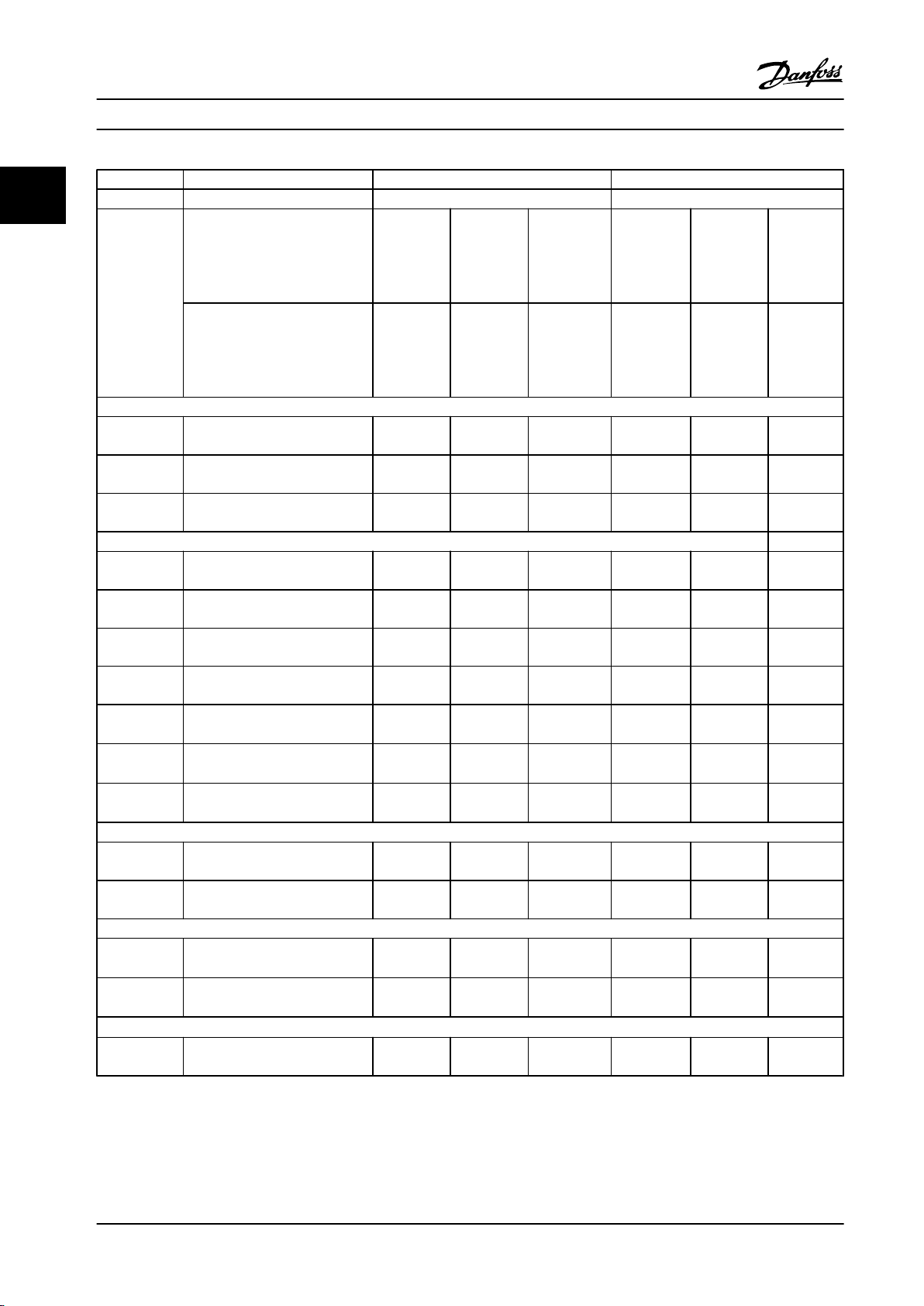
Introduction to VLT® HVAC D...
Design Guide
RFI filter type Conducted emission Radiated emission
22
Standards and
requirements
EN 55011 Class B
Housing,
trades and
industries
EN/IEC 61800-3 Category C1
environment
Home and
Cable length (ft [m]) Cable length (ft [m])
light
First
office
Class A
Group 1
Industrial
environ-
ment
Category C2
First
environment
Home and
office
Class A
Group 2
Industrial
environ-
ment
Category C3
Second
environment
Industrial
Class B
Housing,
trades and
light
industries
Category C1
First
environment
home and
office
Class A
Group 1
Industrial
environment
Category C2
First
environment
home and
office
Class A
Group 2
Industrial
environment
Category C3
Second
environment
Industrial
H1
FC 102
1.5–30 hp [1.1–22 kW]
220–240 V
1.5–60 hp [1.1–45 kW]
200–240 V
1.5–125 hp [1.1–90 kW]
380–480 V
164 [50] 492 [150] 492 [150] No Yes N/A
164 [50] 492 [150] 492 [150] No Yes Yes
164 [50] 492 [150] 492 [150] No Yes Yes
H2
FC 102 1.5–30 hp [1.1–22 kW]
220–240 V
1.5–5 hp [1.1–3.7 kW]
200–240 V
7.5–60 hp [5.5–45 kW]
200–240 V
1.5–10 hp [1.1–7.5 kW]
380–500 V
15–125 hp [11–90 kW]
380–500 V
4)
15–30 hp [11–22 kW]
525–690 V
1, 4)
40–125 hp [30–90 kW]
525–690 V
2, 4)
No No 82 [25] No No N/A
No No 16.4 [5] No No No
No No 82 [25] No No No
No No 16.4 [5] No No No
No No 82 [25] No No No
No No 82 [25] No No No
No No 82 [25] No No No
H3
FC 102
1.5–60 hp [1.1–45 kW]
200–240 V
1.5–125 hp [1.1–90 kW]
380–480 V
33 [10] 164 [50] 250 [75] No Yes Yes
33 [10] 164 [50] 250 [75] No Yes Yes
H4
FC 102
3)
Hx
FC 102
15–40 hp [11–30 kW]
525–690 V
1)
50–125 hp [37–90 kW]
525–690 V
2)
1.5–125 hp [1.1–90 kW]
525–600 V
No 330 [100] 330 [100] No Yes Yes
No 492 [150] 492 [150] No Yes Yes
No No No No No No
Table 2.19 EMC Test Results (Emission)
1) Enclosure Type B
2) Enclosure Type C
3) Hx versions can be used according to EN/IEC 61800-3 category C4
48 Danfoss A/S © Rev. 06/2014 All rights reserved. MG11BC22
Page 51
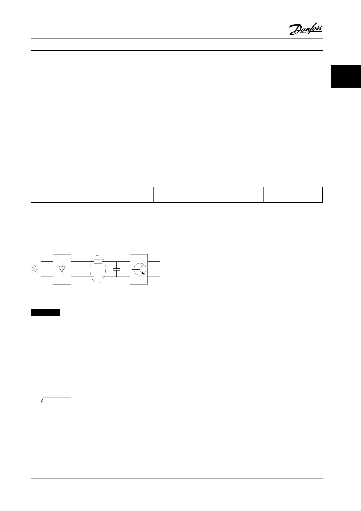
175HA034.10
Introduction to VLT® HVAC D... Design Guide
4) T7, 50–125 hp [37–90 kW] complies with class A group 1 with 82 ft [25 m] motor cable. Some restrictions for the installation apply (contact
Danfoss for details).
HX, H1, H2, H3, H4 or H5 is defined in the type code pos. 16-17 for EMC filters
HX - No EMC filters built in the adjustable frequency drive (600 V units only)
H1 - Integrated EMC filter. Fulfill EN 55011 Class A1/B and EN/IEC 61800-3 Category 1/2
H2 - No additional EMC filter. Fulfill EN 55011 Class A2 and EN/IEC 61800-3 Category 3
H3 - Integrated EMC filter. Fulfill EN 55011 class A1/B and EN/IEC 61800-3 Category 1/2
H4 - Integrated EMC filter. Fulfill EN 55011 class A1 and EN/IEC 61800-3 Category 2
H5 – Marine versions. Fulfill same emissions levels as H2 versions
2.9.3 General Aspects of Harmonics Emission
2 2
An adjustable frequency drive takes up a non-sinusoidal current from the line power, which increases the input current I
A non-sinusoidal current is transformed with a Fourier analysis and split into sine-wave currents with different frequencies,
that is, different harmonic currents In with 50 Hz basic frequency:
Hz 50 250 350
Table 2.20 Harmonic Currents
I
1
I
5
I
7
The harmonics do not affect the power consumption directly, but they do increase the heat losses in the installation
(transformer, cables). So, in plants with a high percentage of rectifier load, maintain harmonic currents at a low level to
avoid overload of the transformer and high temperature in the cables.
Figure 2.33 Harmonic Currents
NOTICE!
Some of the harmonic currents might disturb communication equipment connected to the same transformer or cause
resonance with power-factor correction batteries.
RMS
.
To ensure low harmonic currents, the adjustable frequency drive is equipped with intermediate circuit coils as standard. This
normally reduces the input current I
by 40%.
RMS
The voltage distortion on the line power supply voltage depends on the size of the harmonic currents multiplied by the line
power impedance for the frequency in question. The total voltage distortion THD is calculated based on the individual
voltage harmonics using this formula:
2
2
THD
% =
U
+
5
U
+ ... +
7
2
U
N
(UN% of U)
MG11BC22 Danfoss A/S © Rev. 06/2014 All rights reserved. 49
Page 52
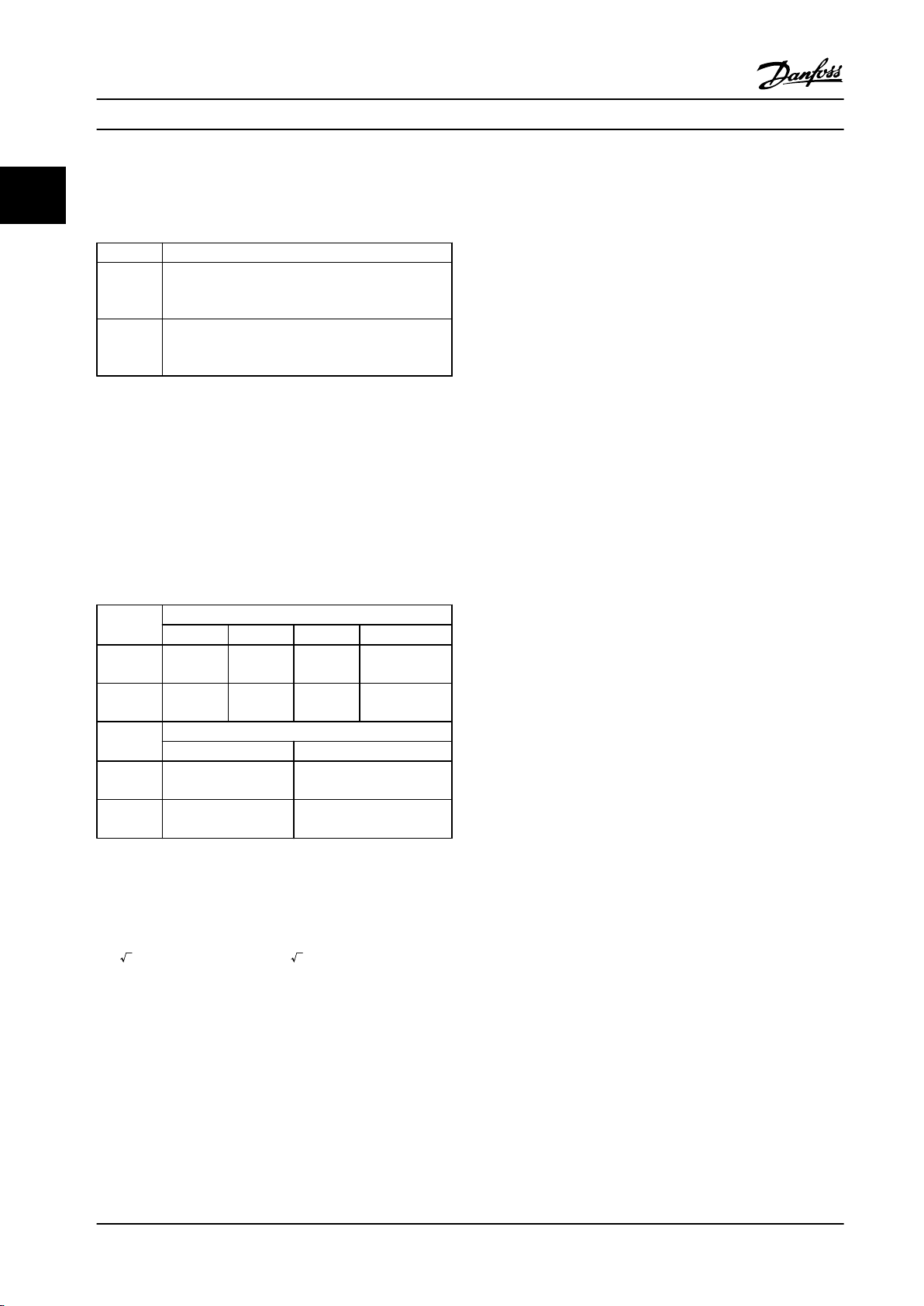
Introduction to VLT® HVAC D...
Design Guide
2.9.4 Harmonics Emission Requirements
22
Equipment connected to the public supply network
Compliance with various system level guidelines:
The harmonic current data in Table 2.22 are given in
accordance with IEC/EN61000-3-12 with reference to the
Power Drive Systems product standard. The data may be
Options Definition
1 IEC/EN 61000-3-2 Class A for 3-phase balanced
equipment (for professional equipment only up to
1 kW total power).
2 IEC/EN 61000-3-12 Equipment 16 A-75 A and profes-
sional equipment as from 1 kW up to 16 A phase
current.
Table 2.21 Connected Equipment
used to calculate the harmonic currents' influence on the
power supply system and to document compliance with
relevant regional guidelines: IEEE 519 -1992; G5/4.
2.9.6 Immunity Requirements
The immunity requirements for adjustable frequency drives
depend on the environment where they are installed. The
requirements for the industrial environment are higher
than the requirements for the home and office
Harmonics Test Results (Emission)
2.9.5
environment. All Danfoss adjustable frequency drives
comply with the requirements for the industrial
Power sizes up to PK75 in T2 and T4 comply with IEC/EN
61000-3-2 Class A. Power sizes from P1K1 and up to P18K
in T2 and up to P90K in T4 comply with IEC/EN
environment and consequently comply also with the lower
requirements for home and office environment with a
large safety margin.
61000-3-12, Table 4. Power sizes P110 - P450 in T4 also
comply with IEC/EN 61000-3-12 even though not required
because currents are above 75 A.
To document immunity against electrical interference from
electrical phenomena, the following immunity tests have
been made in accordance with following basic standards:
Actual
(typical)
Limit for
R
≥120
sce
Actual
(typical)
Limit for
R
≥120
sce
Table 2.22 Harmonics Test Results (Emission)
If the short-circuit power of the supply Ssc is greater than
or equal to:
S
= 3 ×
R
SC
SCE
at the interface point between the user’s supply and the
public system (R
It is the responsibility of the installer or user of the
Individual harmonic current In/I1 (%)
I
5
40 20 10 8
40 25 15 10
Harmonic current distortion factor (%)
×
U
line power
).
sce
I
7
THD PWHD
46 45
48 46
×
I
equ
I
11
= 3 × 120 × 400 ×
I
equ
I
13
EN 61000-4-2 (IEC 61000-4-2): Electrostatic
•
discharges (ESD): Simulation of electrostatic
discharges from human beings.
EN 61000-4-3 (IEC 61000-4-3): Incoming electro-
•
magnetic field radiation, amplitude modulated
simulation of the effects of radar and radio
communication equipment as well as mobile
communications equipment.
EN 61000-4-4 (IEC 61000-4-4): Electrical
•
interference: Simulation of interference brought
about by switching a contactor, relay or similar
devices.
EN 61000-4-5 (IEC 61000-4-5): Surge transients:
•
Simulation of transients brought about, e.g., by
lightning that strikes near installations.
EN 61000-4-6 (IEC 61000-4-6): RF Common
•
mode: Simulation of the effect from radiotransmission equipment joined by connection
cables.
See Table 2.23.
equipment to ensure that the equipment is connected
only to a supply with a short-circuit power Ssc greater than
or equal to what is specified above. If necessary, consult
the distribution network operator.
Other power sizes can be connected to the public supply
network by consultation with the distribution network
operator.
50 Danfoss A/S © Rev. 06/2014 All rights reserved. MG11BC22
Page 53
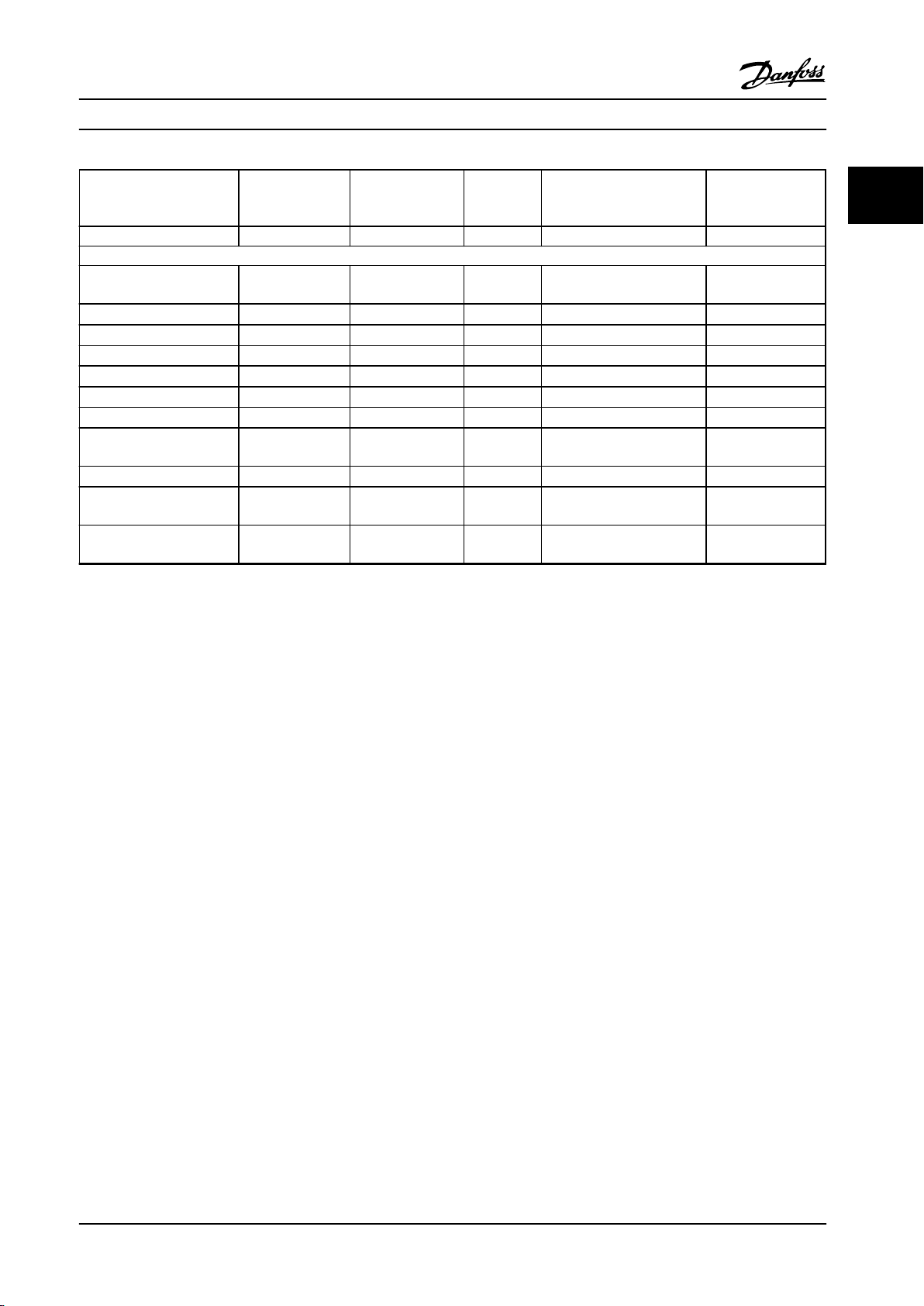
Introduction to VLT® HVAC D...
Design Guide
Basic standard Electrical
interference
IEC 61000-4-4
Surge
IEC 61000-4-5
ESD
IEC
61000-4-2
Radiated electromagnetic
field
IEC 61000-4-3
RF common
mode voltage
IEC 61000-4-6
Acceptance criterion B B B A A
Voltage range: 200–240 V, 380–500 V, 525–600 V, 525–690 V
Line
Motor
4 kV CM
4 kV CM
Brake 4 kV CM
Load sharing 4 kV CM
Control wires
2 kV CM
Standard bus 2 kV CM
Relay wires 2 kV CM
Application and serial
communication options
LCP cable
External 24 V DC
Enclosure
2 kV CM
2 kV CM
2 V CM
— —
2 kV/2 Ω DM
4 kV/12 Ω CM
4 kV/2 Ω
4 kV/2 Ω
4 kV/2 Ω
2 kV/2 Ω
2 kV/2 Ω
2 kV/2 Ω
2 kV/2 Ω
2 kV/2 Ω
1)
1)
1)
1)
1)
1)
1)
1)
0.5 kV/2 Ω DM
1 kV/12 Ω CM
— —
— —
— —
— —
— —
— —
— —
— —
— —
— —
8 kV AD
6 kV CD
10 V
10 V
10 V
10 V
10 V
10 V
10 V
10 V
10 V
10 V
10 V/m —
Table 2.23 EMC Immunity Form
1) Injection on cable shield
AD: Air Discharge
CD: Contact Discharge
CM: Common mode
DM: Differential mode
2 2
RMS
RMS
RMS
RMS
RMS
RMS
RMS
RMS
RMS
RMS
2.10
Galvanic Isolation (PELV)
2.10.1 PELV - Protective Extra Low Voltage
PELV offers protection by way of extra low voltage. Protection against electric shock is ensured when the electrical supply is
of the PELV type and the installation is made as described in local/national regulations on PELV supplies.
All control terminals and relay terminals 01-03/04-06 comply with PELV (Protective Extra Low Voltage), with the exception of
the grounded Delta leg above 400 V.
Galvanic (ensured) isolation is obtained by fulfilling requirements for higher isolation and by providing the relevant
creepage/clearance distances. These requirements are described in the EN 61800-5-1 standard.
The components that make up the electrical isolation, as described below, also comply with the requirements for higher
isolation and the relevant test as described in EN 61800-5-1. The PELV galvanic isolation can be shown in six locations (see
Figure 2.34):
To maintain PELV all connections made to the control terminals must be PELV, e.g., thermistor must be reinforced/double
insulated.
MG11BC22 Danfoss A/S © Rev. 06/2014 All rights reserved. 51
Page 54
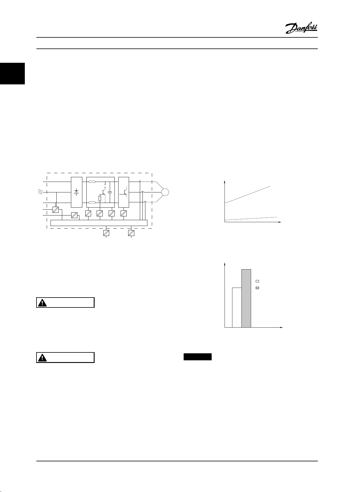
130BC968.10
1325 4
6
b
a
M
7
130BB955.12
a
b
Leakage current
Motor cable length
130BB956.12
THVD=0%
THVD=5%
Leakage current
Introduction to VLT® HVAC D... Design Guide
1. Power supply (SMPS) incl. signal isolation of UDC,
22
indicating the voltage of intermediate DC link
circuit.
2. Gate drive that runs the IGBTs (trigger
transformers/opto-couplers).
3. Current transducers.
4. Opto-coupler, brake module.
5. Internal soft-charge, RFI and temperature
measurement circuits.
6. Custom relays.
7. Mechanical brake.
2.11 Ground Leakage Current
Follow national and local codes regarding protective
grounding of equipment with a leakage current > 3.5 mA.
Adjustable frequency drive technology implies high
frequency switching at high power. This generates a
leakage current in the ground connection. A fault current
in the adjustable frequency drive at the output power
terminals might contain a DC component which can
charge the filter capacitors and cause a transient ground
current.
The ground leakage current is made up from several
contributions and depends on various system configurations including RFI filtering, shielded motor cables and
adjustable frequency drive power.
Figure 2.35 Cable Length and Power Size Influence on
Leakage Current. Pa > Pb
Figure 2.34 Galvanic Isolation
The functional galvanic isolation (a and b in drawing) is for
the 24 V backup option and for the RS-485 standard bus
interface.
WARNING
Installation at high altitude:
380–500 V, enclosure types A, B and C: At altitudes
above 6,600 ft [2 km], contact Danfoss regarding PELV.
525–690 V: At altitudes above 6,600 ft [2 km], contact
Danfoss regarding PELV.
WARNING
Touching the electrical parts could be fatal - even after
the equipment has been disconnected from line power.
Also make sure that other voltage inputs have been
disconnected, such as load sharing (linkage of DC
intermediate circuit), as well as the motor connection for
kinetic backup.
Before touching any electrical parts, wait at least the
amount of time indicated in Table 2.19.
Shorter time is allowed only if indicated on the
nameplate for the specific unit.
52 Danfoss A/S © Rev. 06/2014 All rights reserved. MG11BC22
Figure 2.36 Line Distortion Influences Leakage Current
NOTICE!
When a filter is used, turn off 14-50 RFI 1 when charging
the filter to avoid that a high leakage current makes the
RCD switch.
Page 55
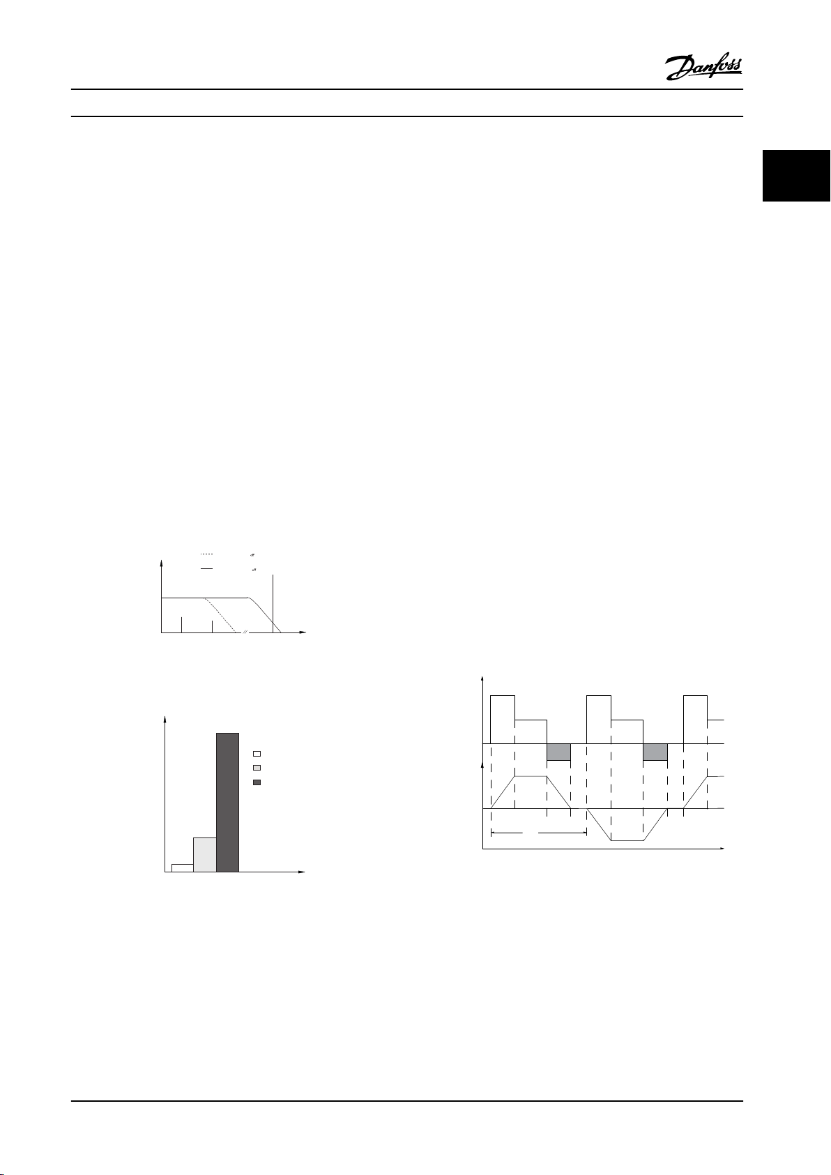
130BB958.12
f
sw
Cable
150 Hz
3rd harmonics
50 Hz
Mains
RCD with low f
cut-
RCD with high f
cut-
Leakage current
Frequency
130BB957.11
Leakage current [mA]
100 Hz
2 kHz
100 kHz
T
ta
tc
tb
to ta
tc
tb
to ta
130BA167.10
Load
Time
Speed
Introduction to VLT® HVAC D...
Design Guide
EN/IEC61800-5-1 (Power Drive System Product Standard)
requires special care if the leakage current exceeds 3.5 mA.
Grounding must be reinforced in one of the following
ways:
Ground wire (terminal 95) of at least 0.016 in
•
2
[10 mm2]
Two separate ground wires both complying with
•
the dimensioning rules
See EN/IEC61800-5-1 and EN50178 for further information.
Using RCDs
Where residual current devices (RCDs), also known as
ground leakage circuit breakers (GLCBs), are used, comply
with the following:
Use RCDs of type B only which are capable of
•
detecting AC and DC currents
Use RCDs with a soft-charge delay to prevent
•
faults due to transient ground currents
Dimension RCDs according to the system configu-
•
ration and environmental considerations
2.12
Brake Function
2.12.1 Selection of Brake Resistor
In certain applications, such as in tunnels or underground
railway station ventilation systems, it is desirable to bring
the motor to a stop more rapidly than can be achieved
through controlling via ramp-down or free-wheeling. In
such applications, dynamic braking with a brake resistor
may be utilized. Using a brake resistor ensures that the
energy is absorbed in the resistor and not in the
adjustable frequency drive.
If the amount of kinetic energy transferred to the resistor
in each braking period is not known, the average power
can be calculated on the basis of the cycle time and
braking time, also known as the intermitted duty cycle.
The resistor intermittent duty cycle is an indication of the
duty cycle at which the resistor is active. Figure 2.39 shows
a typical braking cycle.
The intermittent duty cycle for the resistor is calculated as
follows:
2 2
Duty Cycle = tb / T
T = cycle time in seconds
tb is the braking time in seconds (as part of the total cycle
time)
Figure 2.37 Main Contributions to Leakage Current
Figure 2.39 Intermittent Duty Cycle for the Resistor
Figure 2.38 The Influence of the Cut-off Frequency of the
RCD on What Is Responded to/Measured
Danfoss offers brake resistors with duty cycle of 5%, 10%
and 40% suitable for use with the VLT® HVAC Drive
See also RCD Application Note, MN90G.
adjustable frequency drive series. If a 10% duty cycle
resistor is applied, it is capable of absorbing braking
energy up to 10% of the cycle time, with the remaining
MG11BC22 Danfoss A/S © Rev. 06/2014 All rights reserved. 53
90% being used to dissipate heat from the resistor.
For further selection advice, contact Danfoss.
Page 56
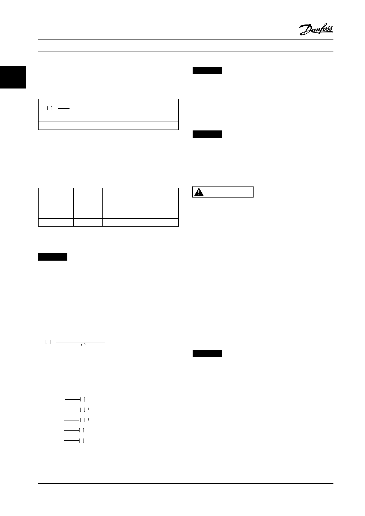
Introduction to VLT® HVAC D...
Design Guide
2.12.2 Brake Resistor Calculation
22
The brake resistance is calculated as shown:
NOTICE!
The brake resistor circuit resistance selected should not
be higher than that recommended by Danfoss. If a brake
resistor with a higher ohmic value is selected, the
2
U
Ω =
P
dc
peak
R
br
where
P
= P
peak
motor
x Mbr x η
motor
x η[W]
Table 2.24 Brake Resistor Calculation
braking torque may not be achieved because there is a
risk that the adjustable frequency drive cuts out for
safety reasons.
NOTICE!
If a short circuit in the brake transistor occurs, power
As can be seen, the brake resistance depends on the
intermediate circuit voltage (UDC).
The brake function of the adjustable frequency drive is
settled in three areas of the line power supply:
Size [V] Brake
active [V]
3x200–240 390 (UDC) 405 410
3x380–480 778 810 820
3x525–690 1084 1109 1130
Table 2.25 Brake Function Settled in Three Areas of Line
Power Supply
Warning before
cut-out [V]
Cut-out (trip)
[V]
dissipation in the brake resistor is only prevented by
using a line switch or contactor to disconnect the line
power for the adjustable frequency drive. (The contactor
can be controlled by the adjustable frequency drive).
WARNING
Do not touch the brake resistor, as it can get very hot
during/after braking.
2.12.3 Control with Brake Function
The brake is protected against short-circuiting of the brake
resistor, and the brake transistor is monitored to ensure
NOTICE!
Make sure that the brake resistor can cope with a
voltage of 410 V, 820 V or 975 V, unless Danfoss brake
resistors are used.
that short-circuiting of the transistor is detected. A relay/
digital output can be used for protecting the brake resistor
against overloading in connection with a fault in the
adjustable frequency drive.
In addition, the brake enables reading out the momentary
power and the mean power for the latest 120 s. The brake
Danfoss recommends the brake resistance R
that guarantees that the is able to brake at the highest
braking torque (M
) of 110%. The formula can be
br(%)
written as:
, i.e., one
rec
can also monitor the power energizing and ensure that it
does not exceed the limit selected in 2-12 Brake Power
Limit (kW). In 2-13 Brake Power Monitoring, select the
function to carry out when the power transmitted to the
brake resistor exceeds the limit set in 2-12 Brake Power
2
U
x 100
P
motor
dc
x
M
br
R
Ω =
rec
η
is typically at 0.90
motor
η is typically at 0.98
%
x x
motor
Limit (kW).
NOTICE!
Monitoring the braking energy is not a safety function; a
For 200 V, 480 V and 600 V adjustable frequency drives,
R
at 160% braking torque is written as:
rec
thermal switch is required for that purpose. The brake
resistor circuit is not ground leakage protected.
200V :
480V :
480V :
600V :
690V :
107780
R
=
rec
R
=
rec
R
=
rec
R
=
rec
R
=
rec
P
motor
375300
P
motor
428914
P
motor
630137
P
motor
832664
P
motor
Ω
Ω
Ω
1
2
Ω
Ω
1) For adjustable frequency drives ≤ 7.5 kW shaft output
2) For adjustable frequency drives > 7.5 kW shaft output
Overvoltage control (OVC) (exclusive brake resistor) can be
selected as an alternative brake function in 2-17 Over-
voltage Control. This function is active for all units. The
function ensures that a trip can be avoided, if the DC link
voltage increases. This is done by increasing the output
frequency to limit the voltage from the DC link. It is a
useful function, e.g., if the ramp-down time is too short
since tripping of the adjustable frequency drive is avoided.
In this situation, the ramp-down time is extended.
54 Danfoss A/S © Rev. 06/2014 All rights reserved. MG11BC22
Page 57
Introduction to VLT® HVAC D...
Design Guide
NOTICE!
OVC cannot be activated when running a PM motor
(when 1-10 Motor Construction is set to [1] PM non salient
SPM).
2.12.4 Brake Resistor Cabling
EMC (twisted cables/shielding)
Twist the wires to reduce the electrical noise from the
wires between the brake resistor and the adjustable
frequency drive.
For enhanced EMC performance, use a metal shield.
2.13 Extreme Running Conditions
Short Circuit (Motor Phase – Phase)
The adjustable frequency drive is protected against short
circuits by current measurement in each of the three
motor phases or in the DC link. A short circuit between
two output phases causes an overcurrent in the inverter.
The inverter is turned off individually when the short
circuit current exceeds the permitted value
(Alarm 16 Trip Lock).
To protect the adjustable frequency drive against a short
circuit at the load sharing and brake outputs, see the
design guidelines.
Switching on the output
Switching on the output between the motor and the
adjustable frequency drive is permitted. Fault messages
may appear. Enable flying start to catch a spinning motor.
Motor-generated overvoltage
The voltage in the intermediate circuit is increased when
the motor acts as a generator. This occurs in following
cases:
The load drives the motor (at constant output
•
frequency from the adjustable frequency drive),
i.e., the load generates energy.
During deceleration (ramp-down) if the moment
•
of inertia is high, the friction is low and the rampdown time is too short for the energy to be
dissipated as a loss in the adjustable frequency
drive, the motor and the installation.
Incorrect slip compensation setting may cause
•
higher DC link voltage.
Back-EMF from PM motor operation. If coasted at
•
high RPM, the PM motor back-EMF may
potentially exceed the maximum voltage
tolerance of the adjustable frequency drive and
cause damage. To help prevent this, the value of
4-19 Max Output Frequency is automatically
limited based on an internal calculation based on
the value of 1-40 Back EMF at 1000 RPM,
1-25 Motor Nominal Speed and 1-39 Motor Poles.
If it is possible that the motor may overspeed
(e.g., due to excessive windmilling effects),
Danfoss recommends using a brake resistor.
WARNING
The adjustable frequency drive must be equipped with a
brake chopper.
The control unit may attempt to correct the ramp if
possible (2-17 Over-voltage Control).
The inverter turns off to protect the transistors and the
intermediate circuit capacitors when a certain voltage level
is reached.
See 2-10 Brake Function and 2-17 Over-voltage Control to
select the method used for controlling the intermediate
circuit voltage level.
NOTICE!
OVC cannot be activated when running a PM motor
(when 1-10 Motor Construction is set to [1] PM non
salient SPM).
Line drop-out
During a line drop-out, the adjustable frequency drive
keeps running until the intermediate circuit voltage drops
below the minimum stop level, which is typically 15%
below the adjustable frequency drive's lowest rated supply
voltage. The AC line voltage before the drop-out and the
motor load determine how long it takes for the inverter to
coast.
Static overload in VVC
When the adjustable frequency drive is overloaded (the
torque limit in 4-16 Torque Limit Motor Mode/4-17 Torque
Limit Generator Mode is reached), the controls reduces the
output frequency to reduce the load.
If the overload is excessive, a current may occur that
makes the adjustable frequency drive cut out after approximately 5-10 s.
Operation within the torque limit is limited in time (0–60 s)
in 14-25 Trip Delay at Torque Limit.
plus
mode
2 2
MG11BC22 Danfoss A/S © Rev. 06/2014 All rights reserved. 55
Page 58
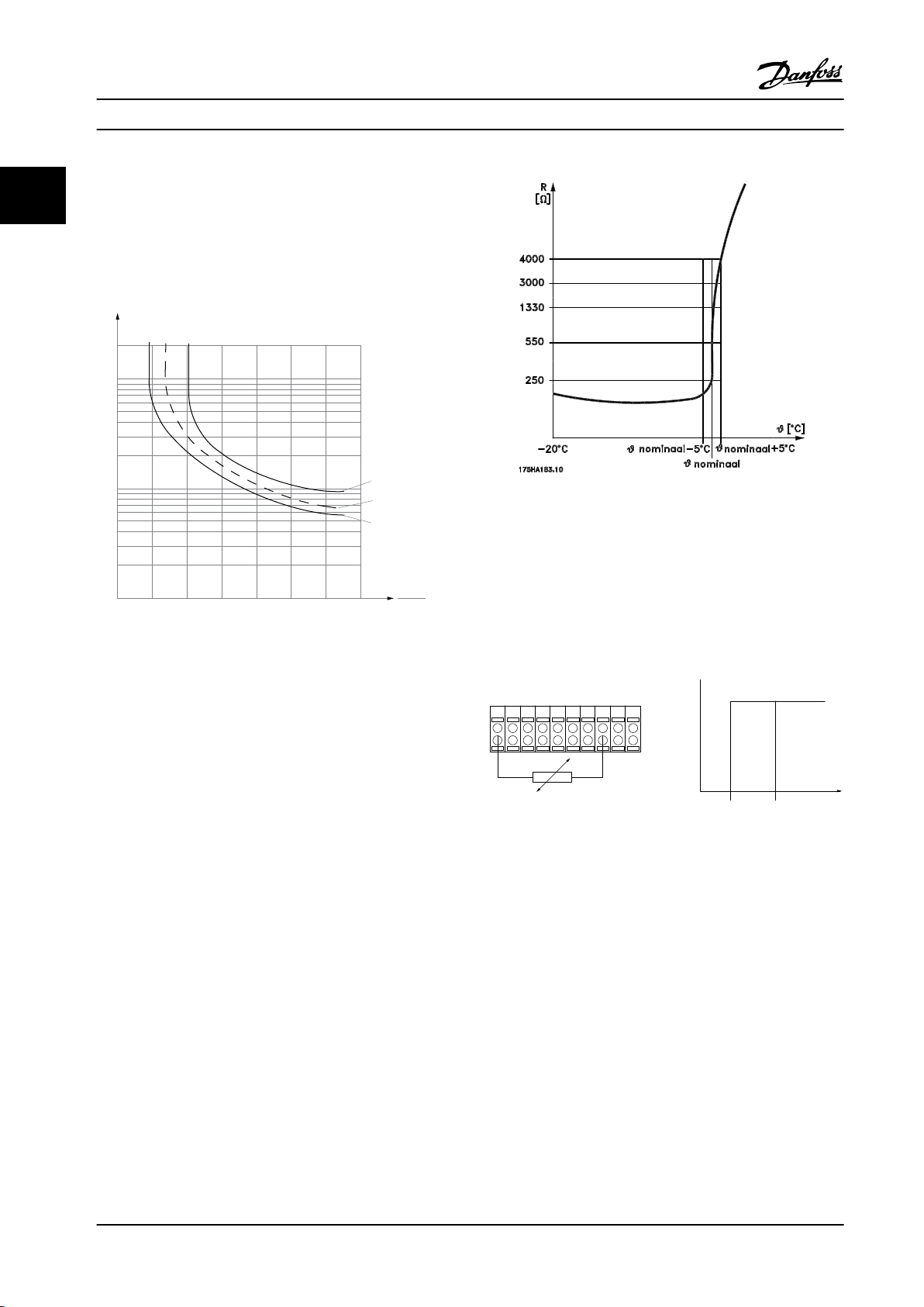
1.21.0 1.4
30
10
20
100
60
40
50
1.81.6 2.0
2000
500
200
400
300
1000
600
t [s]
175ZA052.11
fOUT = 0.2 x f M,N
fOUT = 2 x f M,N
fOUT = 1 x f M,N
IMN
IM
PTC / Thermistor
OFF
ON
+24V
12 13 18 3732
A
2719 29 33B20
GND
R<6.6 k Ω >10.8 k Ω
130BA151.11
Introduction to VLT® HVAC D... Design Guide
2.13.1 Motor Thermal Protection
22
This is the way Danfoss is protecting the motor from being
overheated. It is an electronic feature that simulates a
bimetal relay based on internal measurements.
The characteristic is shown in Figure 2.40
Figure 2.41 The Thermistor Cut-out
Using a digital input and 24 V as power supply:
Example: The adjustable frequency drive trips when the
motor temperature is too high.
Parameter set-up:
Figure 2.40 The X-axis show the ratio between I
nominal. The Y-axis is showing the time in seconds before the
ETR cuts off and trips the adjustable frequency drive. The
curves show the characteristic nominal speed at twice the
nominal speed and at 0.2x the nominal speed.
motor
and I
motor
Set 1-90 Motor Thermal Protection to [2] Thermistor Trip
Set 1-93 Thermistor Source to [6] Digital Input 33
At lower speeds, the ETR cuts off at lower levels due to
reduced cooling of the motor. In that way, the motors are
protected from being overheated even at low speeds. The
ETR feature calculates the motor temperature based on the
actual current and speed. The calculated temperature is
Figure 2.42 Using a Digital Input and 24 V as Power Supply
visible as a readout parameter in 16-18 Motor Thermal in
the adjustable frequency drive.
Using a digital input and 10 V as power supply:
The thermistor cut-out value is > 3 kΩ.
Integrate a thermistor (PTC sensor) in the motor for
winding protection.
Example: The adjustable frequency drive trips when the
motor temperature is too high.
Parameter set-up:
Set 1-90 Motor Thermal Protection to [2] Thermistor Trip
Set 1-93 Thermistor Source to [6] Digital Input 33
Motor protection can be implemented using a range of
techniques: PTC sensor in motor windings; mechanical
thermal switch (Klixon type); or Electronic Thermal Relay
(ETR).
56 Danfoss A/S © Rev. 06/2014 All rights reserved. MG11BC22
Page 59
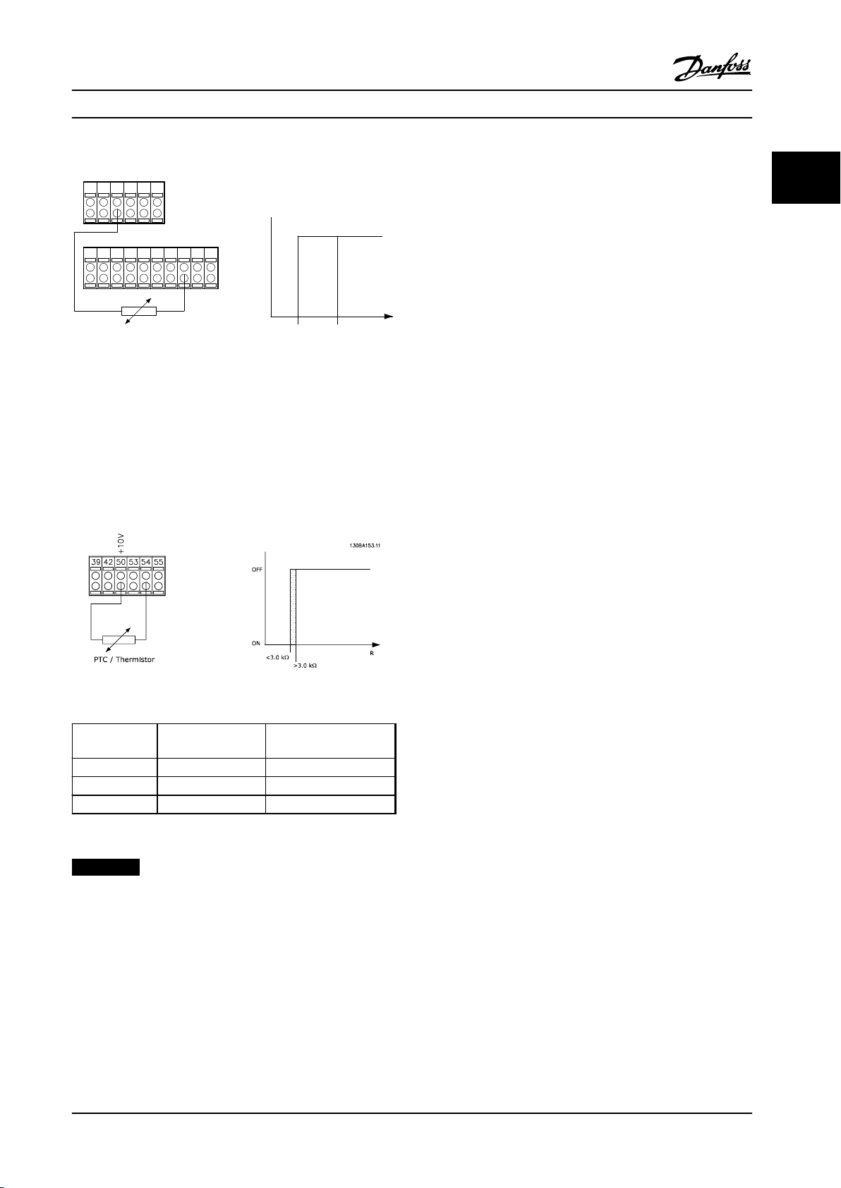
PTC / Thermistor
R
OFF
ON
<800 Ω
+10V
130BA152.10
>2.7 kΩ
12 13 18 37322719 29 33 20
5550
39 42 53 54
Introduction to VLT® HVAC D... Design Guide
Figure 2.43 Using a Digital Input and 10 V as Power Supply
Using an analog input and 10 V as power supply:
Example: The adjustable frequency drive trips when the
motor temperature is too high.
Parameter set-up:
Set 1-90 Motor Thermal Protection to [2] Thermistor Trip
Set 1-93 Thermistor Source to [2] Analog Input 54
Do not select a reference source.
Summary
With the torque limit feature the motor is protected for
being overloaded independent of the speed. With the ETR,
the motor is protected from being overheated and there is
no need for any further motor protection. That means
when the motor is heated up, the ETR timer controls for
how long time the motor can be running at the high
temperature before it is stopped to prevent overheating. If
the motor is overloaded without reaching the temperature
where the ETR shuts off the motor, the torque limit
protects the motor and application for becoming
overloaded.
ETR is activated in 1-90 Motor Thermal Protection and is
controlled in 4-16 Torque Limit Motor Mode. The time
before the torque limit warning trips the adjustable
frequency drive is set in 14-25 Trip Delay at Torque Limit.
2 2
Figure 2.44 Using an Analog Input and 10 V as Power Supply
Input
Digital/analog
Digital 24
Digital 10
Analog 10
Table 2.26 Threshold Cut-out Values
NOTICE!
Ensure that the chosen supply voltage follows the
specification of the thermistor element utilized.
MG11BC22 Danfoss A/S © Rev. 06/2014 All rights reserved. 57
Supply Voltage V
Cut-out Values
Threshold
Cut-out Values
< 6.6 kΩ - > 10.8 kΩ
< 800 Ω - > 2.7 kΩ
< 3.0 kΩ - > 3.0 kΩ
Page 60
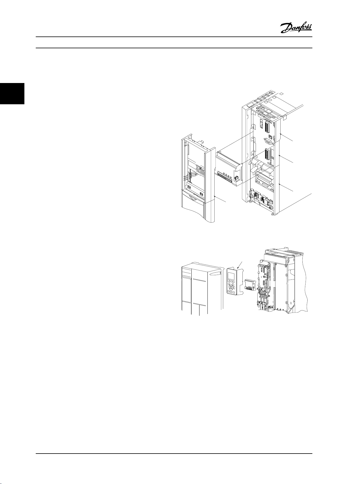
LCP
Frame
A
B
D
130BA707.10
XXXN1100
3x380-480V 50/60Hz 14.9A
OUT: 3x0-Uin 0-1000Hz 16.0A 11.1 kVA
CHASIS/IP20 Tamb Max 45C/113F
MADE IN DENMARK
CAUTION:
SEE MANUAL / RCD and high leakage current
VOIR MANUAL / Fransk tekst
WARNING:
Stored charge / “Fransk tekst” (4 min.)
LISTED 76x1 134261
INDUSTRIAL CONTROL EQUIPMENT
SEE MANUAL FOR PREFUSE TUPE IN UL
APPLICATIONS
LCP
Cradle
DC-
DC+
130BA708.10
13
12
18
19
27
28
32
38
2
42
39
53
50
5
61
6
Remove jumper to activate Safe Stop
9Ø
9Ø
Selection Design Guide
3 Selection
33
3.1 Options and Accessories
Danfoss offers a wide range of options and accessories for
adjustable frequency drives.
3.1.1 Mounting Option Modules in Slot B
Disconnect power to the adjustable frequency drive.
For A2 and A3 enclosure types:
1. Remove the LCP, the terminal cover, and the LCP
frame from the adjustable frequency drive.
2. Fit the MCB1xx option card into slot B.
3. Connect the control cables and fasten the cables
with the enclosed cable strips.
Remove the knockout in the extended LCP frame
delivered in the option set so that the option fits
under the extended LCP frame.
4. Fit the extended LCP frame and terminal cover.
5. Fit the LCP or blind cover in the extended LCP
frame.
6. Connect power to the adjustable frequency drive.
7. Set up the input/output functions in the
corresponding parameters, as mentioned in
chapter 9.2 General Specifications.
For B1, B2, C1 and C2 enclosure types:
Figure 3.1 A2, A3 and B3 Enclosure Types
1. Remove the LCP and the LCP cradle.
2. Fit the MCB 1xx option card into slot B.
Figure 3.2 A5, B1, B2, B4, C1, C2, C3 and C4 Enclosure Types
3. Connect the control cables and fasten the cables
with the enclosed cable strips.
4. Fit the cradle.
5. Fit the LCP.
58 Danfoss A/S © Rev. 06/2014 All rights reserved. MG11BC22
Page 61
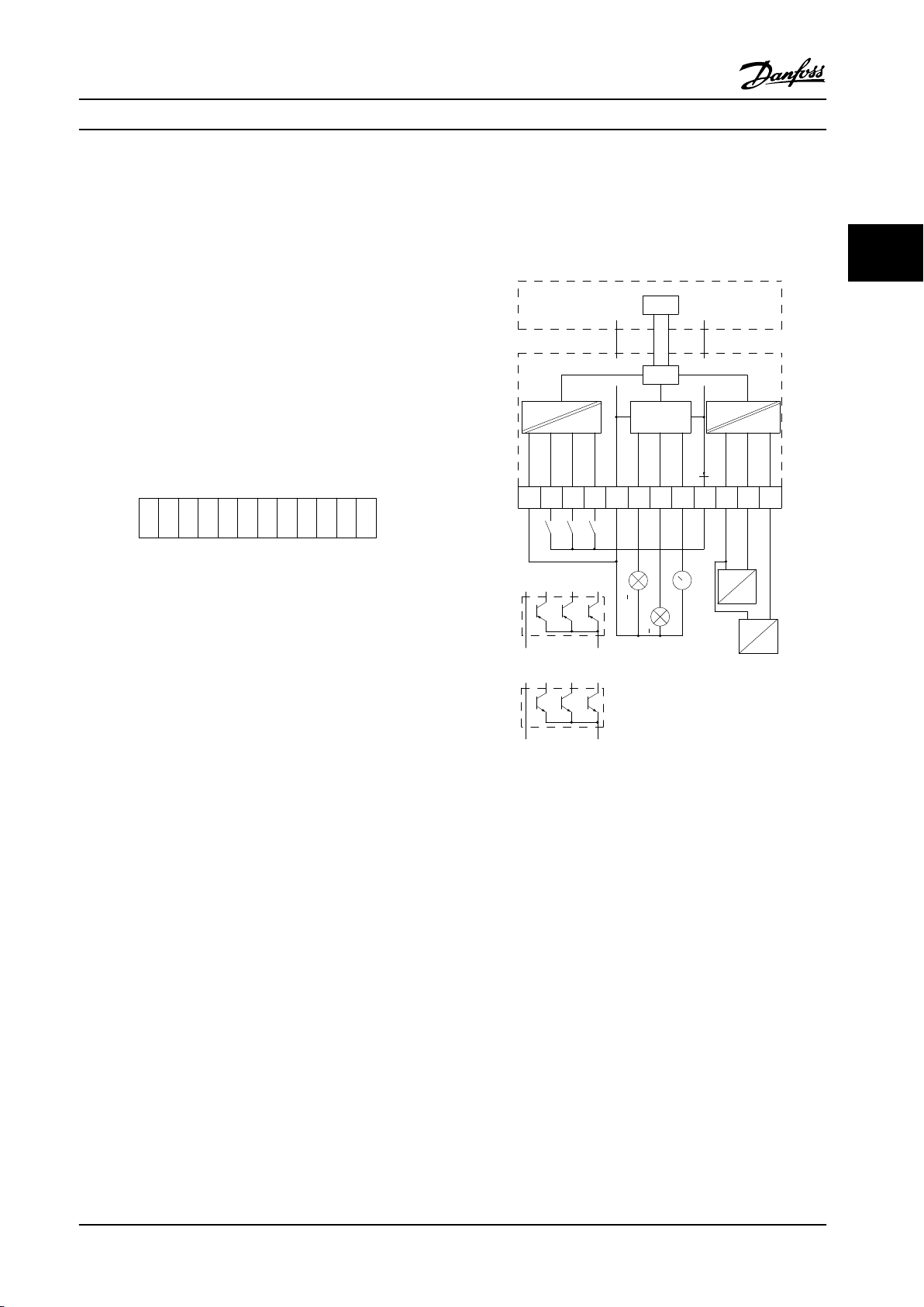
General Purpose I/O
SW. ver. XX.XX
MCB 101
FC Series
Code No. 130BXXXX
B slot
X30/
AIN4
7 8654321 9 10 11 12
AIN3
GND(2)
24V
AOUT2
DOUT4
DOUT3
GND(1)
DIN7
COM
DIN
DIN8
DIN9
130BA208.10
130BA209.10
1
2 3
4 5
6
7
8
9 10
11
12
COM DIN
DIN7
DIN8
DIN9
GND(1)
DOUT3
0/24VDC
DOUT4
0/24VDC
AOUT2
0/4-20mA
24V
GND(2)
AIN3
AIN4
RIN=
5kohm
RIN=
10kohm
0-10
VDC
0-10
VDC
0V 24V
0V 24V
24V DC0V
0V24V DC
<500 ohm
>600 ohm
>600 ohm
X30/
DIG IN
DIG &
ANALOG
OUT
ANALOG
IN
CPU
CAN BUS
CPU
Control card (FC 100/200/300)
General Purpose
I/O option MCB 101
PLC
(PNP)
PLC
(NPN)
Selection Design Guide
3.1.2 General Purpose I/O Module MCB 101
MCB 101 is used for extension of the number of digital
and analog inputs and outputs of the adjustable frequency
drive.
MCB 101 must be fitted into slot B in the adjustable
frequency drive. Contents:
MCB 101 option module
•
Extended LCP frame
•
Terminal cover
•
Figure 3.3
Galvanic isolation in the MCB 101
Digital/analog inputs are galvanically isolated from other
inputs/outputs on the MCB 101 and in the control card of
the adjustable frequency drive. Digital/analog outputs in
the MCB 101 are galvanically isolated from other inputs/
outputs on the MCB 101, but not from these on the
control card of the adjustable frequency drive.
If the digital inputs 7, 8 or 9 are to be switched by use of
the internal 24 V power supply (terminal 9) the connection
between terminal 1 and 5 which is shown in Figure 3.4 has
to be established.
3 3
Figure 3.4 Principle Diagram
MG11BC22 Danfoss A/S © Rev. 06/2014 All rights reserved. 59
Page 62
Selection Design Guide
3.1.3 Digital Inputs - Terminal X30/1-4
Number of
digital inputs
33
3 0–24 V DC PNP type:
Table 3.1 Parameters for set-up: 5-16, 5-17 and 5-18
Analog Voltage Inputs - Terminal X30/10-12
3.1.4
Number of analog voltage inputs Standardized input signal Tolerance Resolution Max. Input impedance
2 0–10 V DC
Table 3.2 Parameters for set-up: 6-3*, 6-4* and 16-76
Digital Outputs - Terminal X30/5-7
3.1.5
Number of digital outputs Output level Tolerance Max.impedance
2 0 or 2 V DC
Voltage level Voltage levels Tolerance Max. Input impedance
Common = 0 V
Logic “0”: Input < 5 V DC
Logic “0”: Input > 10 V DC
NPN type:
Common = 24 V
Logic “0”: Input > 19 V DC
Logic “0”: Input < 14 V DC
± 28 V continuous
± 37 V in minimum 10 s
± 20 V continuously
± 4 V ≥ 600 Ω
10 bits
Approx. 5 kΩ
Approx. 5 KΩ
Table 3.3 Parameters for set-up: 5-32 and 5-33
Analog Outputs - Terminal X30/5+8
3.1.6
Number of analog outputs Output signal level Tolerance Max. impedance
1 0/4–20 mA
Table 3.4 Parameters for set-up: 6-6* and 16-77
±0.1 mA < 500 Ω
60 Danfoss A/S © Rev. 06/2014 All rights reserved. MG11BC22
Page 63
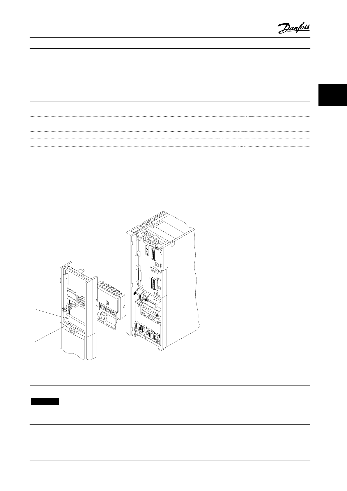
2
130BA709.11
1
LABEL
Remove jumper to activate Safe Stop
12
13
18
19
27
29
33
32
20
39
42
50
53
54
61
68
CAUTION:
SEE MANUAL / RCD and high leakage current
VOIR MANUAL / Fransk tekst
WARNING:
Stored charge / “Fransk tekst” (4 min.)
LISTED 76x1 134261
INDUSTRIAL CONTROL EQUIPMENT
SEE MANUAL FOR PREFUSE TUPE IN UL
APPLICATIONS
T/C : CIAXXXPT5B20BR1DBF00A00
P/N : XXXN1100 S/N: 012815G432
IN: 3x380-480V 50/60Hz 14.9A
OUT: 3x0-Uin 0-1000Hz 16.0A 11.1 kVA
CHASIS/IP20 Tamb Max 45C/113F
MADE IN DENMARK
9Ø
9Ø
Ø6
Selection
Design Guide
3.1.7 Relay Option MCB 105
The MCB 105 option includes three pieces of SPDT contacts and must be fitted into option slot B.
Electrical Data:
Max terminal load (AC-1)1) (Resistive load) 240 V AC 2A
Max terminal load (AC-15)1) (Inductive load @ cosφ 0.4) 240 V AC 0.2 A
Max terminal load (DC-1)1) (Resistive load) 24 V DC 1 A
Max terminal load (DC-13)
1)
(Inductive load) 24 V DC 0.1 A
Min terminal load (DC) 5 V 10 mA
Max switching rate at rated load/min load 6 min-1/20 s
1)
IEC 947 part 4 and 5
When the relay option kit is ordered separately, the kit includes:
Relay Module MCB 105
•
Extended LCP frame and enlarged terminal cover
•
Label for covering access to switches S201, S202 and S801
•
Cable strips for fastening cables to relay module
•
3 3
-1
Figure 3.5 Relay Option MCB 105
A2-A3-A4-B3
A5-B1-B2-B4-C1-C2-C3-C4
NOTICE!
1)
IMPORTANT! The label MUST be placed on the LCP frame as shown (UL-approved).
Table 3.5 Legend to Figure 3.5 and Figure 3.6
MG11BC22 Danfoss A/S © Rev. 06/2014 All rights reserved. 61
Page 64
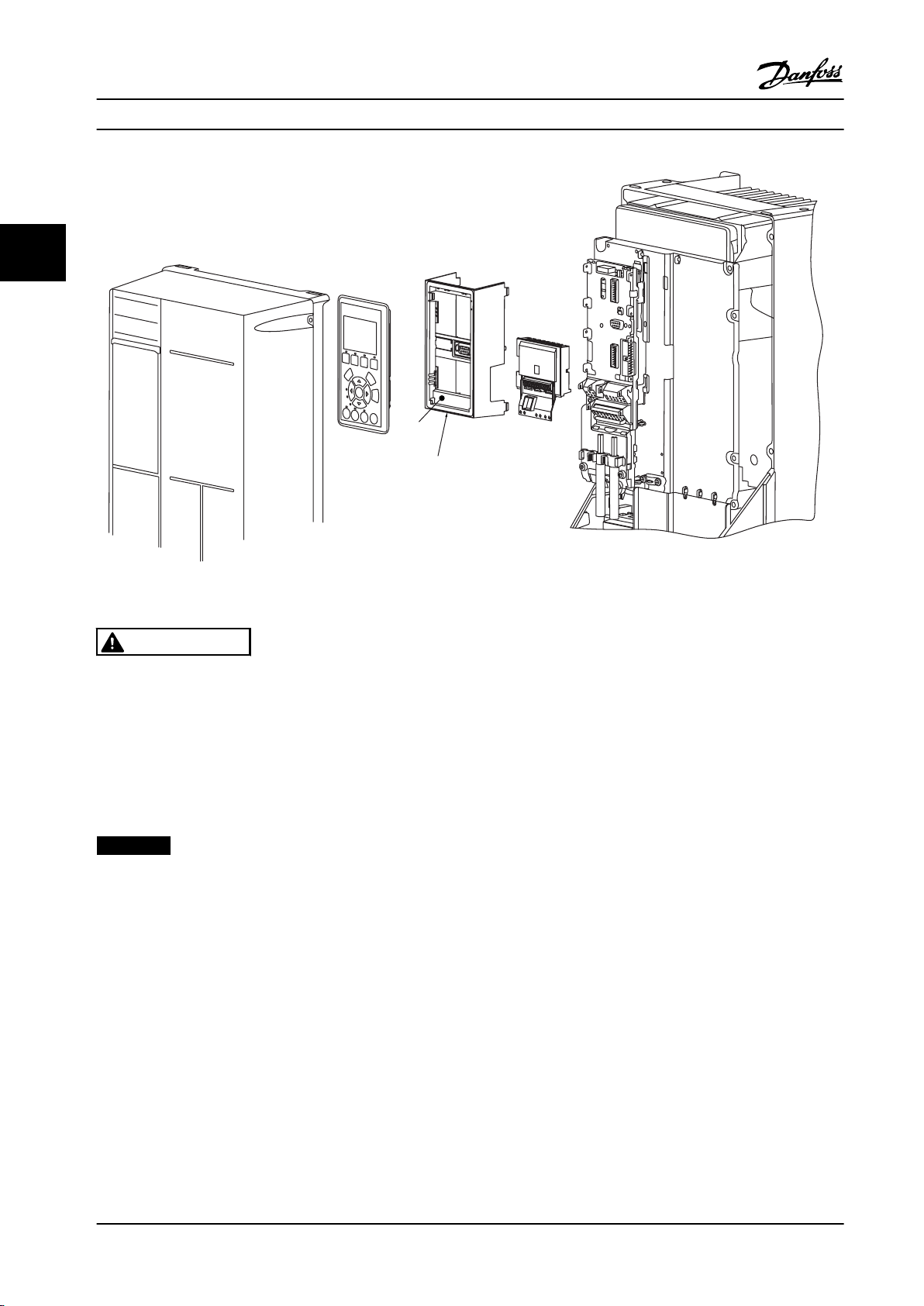
2
130BA710.11
1
LABEL
Remove jumper to activate Safe Stop
13
12
18
19
27
32
38
2
28
42
39
53
50
5
61
6
9Ø
9Ø
DC-
DC+
Selection Design Guide
33
Figure 3.6 Relay Option Kit
WARNING
Warning Dual supply.
How to add the MCB 105 option:
See the mounting instructions at the beginning of the section Options and Accessories.
•
Disconnect power to the live part connections on relay terminals.
•
Do not mix live parts with control signals (PELV).
•
Select the relay functions in 5-40 Function Relay [6-8], 5-41 On Delay, Relay [6-8] and 5-42 Off Delay, Relay [6-8].
•
NOTICE!
Index [6] is relay 7, index [7] is relay 8, and index [8] is relay 9.
62 Danfoss A/S © Rev. 06/2014 All rights reserved. MG11BC22
Page 65
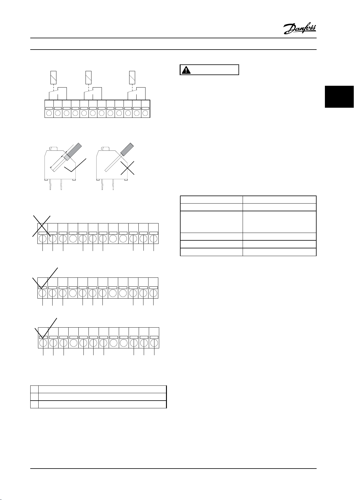
Relay 7
NC NCNC
Relay 9Relay 8
1 2 3 12
130BA162.10
754 6 8 9 10 11
130BA177.10
8-9mm
2mm
1 1 1
1 102 3 4 5 6 7 8 9 1211
2 2 3
1 1 1
1 102 3 4 5 6 7 8 9 1211
3 3 3
1 1 1
1 102 3 4 5 6 7 8 9 1211
2 2
2
130BA176.11
Selection
Design Guide
WARNING
Do not combine low voltage parts and PELV systems.
At a single fault the whole system might become
dangerous to touch, and it could result in death or
serious injury.
3 3
Figure 3.7 Relay 7, Relay 8, and Relay 9
Figure 3.8 Mounting
3.1.8 24 V Backup Option MCB 107 (Option
D)
External 24 V DC Supply
An external 24 V DC supply can be installed for lowvoltage supply to the control card and any option card
installed. This enables full operation of the LCP (including
the parameter setting) and serial communication busses
without line power supplied to the power section.
Input voltage range
Max. input current 2.2 A
Average input current for
the adjustable frequency
drive
Max cable length 250 ft [75 m]
Input capacitance load
Power-up delay
Table 3.7 External 24 V DC Supply Specification
The inputs are protected.
24 V DC ±15% (max. 37 V in 10 s)
0.9 A
<10 uF
<0.6 s
Figure 3.9 Connection
1 NC
2 Live part
3 PELV
Table 3.6 Legend to Figure 3.9
MG11BC22 Danfoss A/S © Rev. 06/2014 All rights reserved. 63
Terminal numbers:
Terminal 35: - external 24 V DC supply.
Terminal 36: + external 24 V DC supply.
Follow these steps:
1. Remove the LCP or blind cover.
2. Remove the terminal cover.
3. Remove the cable decoupling plate and the
plastic cover underneath.
4. Insert the 24 V DC backup external supply option
in the option slot.
5. Mount the cable de-coupling plate.
6. Attach the terminal cover and the LCP or blind
cover.
Page 66
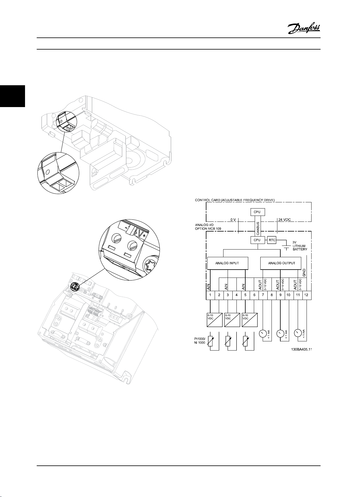
35
36
35
36
130BA028.11
9
9
6
311
130BA216.10
35 36
Selection Design Guide
When 24 V backup option MCB 107 supplies the control
Analog I/O option MCB 109
3.1.9
circuit, the internal 24 V supply is automatically
disconnected.
The Analog I/O card is to be used, e.g., in the following
cases:
33
Providing battery backup of clock function on
•
control card
As general extension of analog I/O selection
•
available on control card, e.g., for multi-zone
control with three pressure transmitters
Turning the adjustable frequency drive into a de-
•
central I/O block supporting a Building
Management System with inputs for sensors and
outputs for operating dampers and valve servos
Support Extended PID controllers with I/Os for
•
setpoint inputs, transmitter/sensor inputs and
outputs for servos
Figure 3.10 Connection to 24 V Backup Supplier (A2-A3).
Figure 3.11 Connection to 24 V Backup Supplier (A5-C2).
64 Danfoss A/S © Rev. 06/2014 All rights reserved. MG11BC22
Figure 3.12 Principle Diagram for Analog I/O Mounted in
Adjustable Frequency Drive.
Page 67
Selection
Design Guide
Analog I/O configuration
3 x analog inputs, capable of handling following:
0–10 V DC
•
OR
0–20 mA (voltage input 0–10 V) by mounting a
•
510 Ω resistor across terminals (see NOTICE)
4–20 mA (voltage input 2–10 V) by mounting a
•
510 Ω resistor across terminals (see NOTICE)
Ni1000 temperature sensor of 1000 Ω at 32 °F
•
[0 °C]. Specifications according to DIN43760
Pt1000 temperature sensor of 1000 Ω at 32 °F
•
[0 °C]. Specifications according to IEC 60751
3 x Analog Outputs supplying 0–10 V DC.
NOTICE!
Note the values available within the different standard
groups of resistors:
E12: Closest standard value is 470 Ω, creating an input of
449.9 Ω and 8.997 V.
E24: Closest standard value is 510 Ω, creating an input of
486.4Ω and 9.728 V.
E48: Closest standard value is 511 Ω, creating an input of
487.3 Ω and 9.746 V.
E96: Closest standard value is 523 Ω, creating an input of
498.2 Ω and 9.964 V.
When used for voltage, analog inputs are scalable by
parameters for each input.
When used for temperature sensor, analog inputs scaling is
preset to necessary signal level for specified temperature
span.
When analog inputs are used for temperature sensors, it is
possible to read out the feedback value in both °C and °F.
When operating with temperature sensors, maximum cable
length to connect sensors is 270 ft [82 m] non-shielded/
non-twisted wires.
Analog outputs - terminal X42/7-12
Parameter group: 18-3*. See also VLT® HVAC Drive
Programming Guide.
Parameter groups for set-up: 26-4*, 26-5* and 26-6*.
®
See also VLT
3 x analog
outputs
Volt 0–10 V DC 11 bits 1% of full
Table 3.9 Analog outputs - terminal X42/7-12
HVAC Drive Programming Guide.
Output
signal level
Resolution Linearity Max load
scale
1 mA
Analog outputs are scalable by parameters for each
output.
3 3
Analog inputs - terminal X42/1-6
Parameter group: 18-3*. See also VLT® HVAC Drive
Programming Guide.
Parameter groups for set-up: 26-0*, 26-1*, 26-2* and 26-3*.
®
See also VLT
3 x analog
inputs
Operating
range
Resolution
Accuracy
Sampling
Max load
Impedance
Table 3.8 Analog inputs - terminal X42/1-6
HVAC Drive Programming Guide.
Used as temperature
sensor input
-58–+302 °F
[-50–+150 °C]
11 bits 10 bits
-58 °F [-50 °C]
±1 Kelvin
302 °F [+150 °C]
±2 Kelvin
3 Hz 2.4 Hz
- ± 20 V continuously
-
Used as voltage input
0–10 V DC
0.2% of full
scale at cal.
temperature
Approximately 5 kΩ
The function assigned is selectable via a parameter and
has the same options as for analog outputs on the control
card.
For a more detailed description of parameters, refer to the
VLT® HVAC Drive Programming Guide.
Real time clock (RTC) with backup
The data format of RTC includes year, month, date, hour,
minutes and weekday.
Accuracy of clock is better than ± 20 ppm at 77 °F [25 °C].
The built-in lithium backup battery lasts on average for
minimum 10 years, when adjustable frequency drive is
operating at 104 °F [40 °C] ambient temperature. If the
battery backup pack fails, the analog I/O option must be
replaced.
MG11BC22 Danfoss A/S © Rev. 06/2014 All rights reserved. 65
Page 68
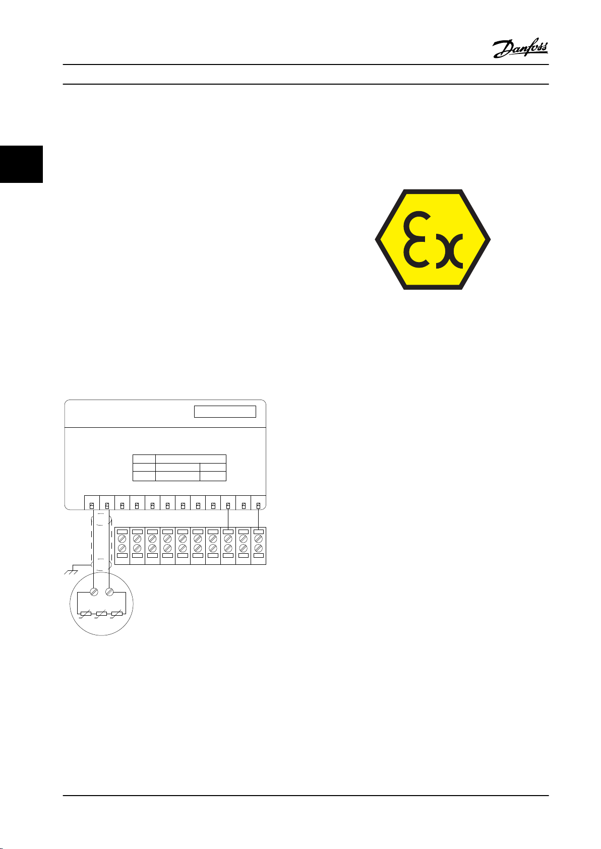
MS 220 DA
11
10
20-28 VDC 10 mA
12
20-28 VDC
60 mA
com
ZIEHL
X44
12 13 18 19 27 29 32 33 20 37
3
NC
4NC5NC6NC7NC8NC9NC10 11NC121
T1
2
T2
T
P
T
P
PTC
M3~
130BA638.10
DO
Motor protection
MCB 112 PTC Thermistor Card
Option B
Reference for 10, 12
DO FOR SAFE
STOP T37
Code No.130B1137
Control Terminals of FC302
Selection Design Guide
3.1.10 PTC Thermistor Card MCB 112
ATEX Certification with FC 102
The MCB 112 has been certified for ATEX, which means
The MCB 112 option makes it possible to monitor the
temperature of an electrical motor through a galvanically-
33
isolated PTC thermistor input. It is a B option for adjustable
frequency drive with Safe Torque Off.
that the adjustable frequency drive with the MCB 112 can
now be used with motors in potentially explosive
atmospheres. See the Instruction Manual for the MCB 112
for more information.
For information on mounting and installation of the
option, see chapter 3.1.1 Mounting Option Modules in Slot B.
See also chapter 7 Application Examples for different
application possibilities.
X44/1 and X44/2 are the thermistor inputs. X44/12 enables
Safe Torque Off of the adjustable frequency drive (T-37), if
the thermistor values make it necessary, and X44/10
informs the adjustable frequency drive that a request for
Figure 3.14 ATmosphère EXplosive (ATEX)
safe torque off came from the MCB 112 to ensure a
suitable alarm handling. One of the digital inputs
parameters (or a digital input of a mounted option) must
be set to [80] PTC Card 1 to use the information from
X44/10. Configure 5-19 Terminal 37 Safe Stop to the desired
Safe Torque Off functionality (default is Safe Stop Alarm).
Figure 3.13 Installation of MCB 112
66 Danfoss A/S © Rev. 06/2014 All rights reserved. MG11BC22
Page 69
Selection
Electrical Data
Resistor connection
PTC compliant with DIN 44081 and DIN 44082.
Number 1..6 resistors in series
Shut-off value 3.3 Ω.... 3.65 Ω.... 3.85 Ω
Reset value 1.7 Ω.... 1.8 Ω... 1.95 Ω
Trigger tolerance ± 11 °F [± 6 °C]
Collective resistance of the sensor loop < 1.65 Ω
Terminal voltage ≤ 2.5 V for R ≤ 3.65 Ω, ≤ 9 V for R = ∞
Sensor current ≤ 1 mA
Short-circuit 20 Ω ≤ R ≤ 40 Ω
Power consumption 60 mA
Testing conditions
EN 60 947-8
Measurement voltage surge resistance 6000 V
Overvoltage category III
Pollution degree 2
Measurement isolation voltage Vbis 690 V
Reliable galvanic isolation until Vi 500 V
Perm. ambient temperature -4–+140 °F [-20–+60 °C]
Moisture 5–95%, no condensation permissible
EMC resistance EN61000-6-2
EMC emissions EN61000-6-4
Vibration resistance 10 ... 1000 Hz 1.14 g
Shock resistance 50 g
Design Guide
EN 60068-2-1 Dry heat
3 3
Safety system values
EN 61508 for Tu = 75 °C ongoing
SIL 2 for maintenance cycle of 2 years
1 for maintenance cycle of 3 years
HFT 0
PFD (for yearly functional test) 4.10 *10
SFF 78%
λs + λ
DD
λ
DU
Ordering number 130B1137
8494 FIT
934 FIT
3.1.11 Sensor Input Option MCB 114
The sensor input option card MCB 114 can be used in the following cases:
Sensor input for temperature transmitters PT100 and PT1000 for monitoring bearing temperatures
•
As general extension of analog inputs with one additional input for multi-zone control or differential pressure
•
measurements
Support extended PID controllers with I/Os for setpoint, transmitter/sensor inputs
•
Typical motors, designed with temperature sensors for protecting bearings from being overloaded, are fitted with three
PT100/1000 temperature sensors. One in front, one in the back-end bearing, and one in the motor windings. The sensor
input Option MCB 114 supports two or three-wire sensors with individual temperature limits for under/over temperature.
An auto detection of sensor type PT100 or PT1000 takes place at power-up.
-3
MG11BC22 Danfoss A/S © Rev. 06/2014 All rights reserved. 67
Page 70
Selection Design Guide
The option can generate an alarm if the measured temperature is either below low limit or above high limit specified by
the user. The individual measured temperature on each sensor input can be read out in the display or by readout
parameters. If an alarm occurs, the relays or digital outputs can be programmed to be active high by selecting [21] Thermal
Warning in parameter group 5-**.
33
A fault condition has a common warning/alarm number associated with it, which is Alarm/Warning 20, Temp. input error.
Any present output can be programmed to be active in case the warning or alarm appears.
3.1.11.1 Ordering Code Numbers and Parts Delivered
Standard version code no: 130B1172.
Coated version code no: 130B1272.
3.1.11.2
Analog Input
Number of analog inputs 1
Format 0–20 mA or 4–20 mA
Wires 2
Input impedance <200 Ω
Sample rate 1 kHz
Third order filter 100 Hz at 3 dB
The option is able to supply the analog sensor with 24 V DC (terminal 1).
Temperature Sensor Input
Number of analog inputs supporting PT100/1000 3
Signal type PT100/1000
Connection PT 100 2 or 3 wire/PT1000 2 or 3 wire
Frequency PT100 and PT1000 input 1Hz for each channel
Resolution 10 bit
Temperature range
Galvanic Isolation
The sensors to be connected are expected to be galvanically isolated from the AC line voltage
level. IEC 61800-5-1 and UL508C
Electrical and Mechanical Specifications
-50–+204 °C
-58–+399 °F
Cabling
Maximum signal cable length 1640 ft [500 m]
68 Danfoss A/S © Rev. 06/2014 All rights reserved. MG11BC22
Page 71
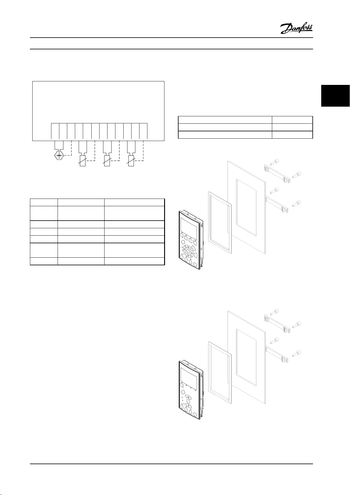
MCB 114
Sensor Input Option B
SW. ver. xx.xx Code No. 130B1272
VDD
I IN
GND
TEMP
1
WIRE
1
GND
TEMP 2 WIRE
2
GND
TEMP 3 WIRE
3
GND
X48/
1 2 3 4 5 6 7 8 9
10
11
12
4-20mA
2 or 3
wire
2 or 3
wire
2 or 3
wire
2 or 3
wire
130BB326.10
130BA138.10
130BA200.10
Selection Design Guide
3.1.11.3 Electrical Wiring
Figure 3.15 Electrical Wiring
Terminal Name Function
1 VDD 24 V DC to supply 4–20 mA
sensor
2 I in 4–20 mA input
3 GND Analog input GND
4, 7, 10 Temp 1, 2, 3 Temperature input
5, 8, 11 Wire 1, 2, 3 Third wire input if three
wire sensors are used
6, 9, 12 GND Temp. input GND
3.1.12
Remote Mounting Kit for LCP
The LCP can be moved to the front of a cabinet by using
the remote built-in kit. The enclosure is the IP66. The
fastening screws must be tightened with a torque of max.
1 Nm.
Enclosure IP66 front
Max. cable length between and unit 10 ft [3 m]
Communication std RS-485
Table 3.11 Technical Data
3 3
Table 3.10 Terminals
Figure 3.16 LCP Kit with Graphical LCP, Fasteners, 10 ft [3 m]
Cable and Gasket
Ordering No. 130B1113
Figure 3.17 LCP Kit with Numerical LCP, Fasteners and Gasket
Ordering no. 130B1114
MG11BC22 Danfoss A/S © Rev. 06/2014 All rights reserved. 69
Page 72
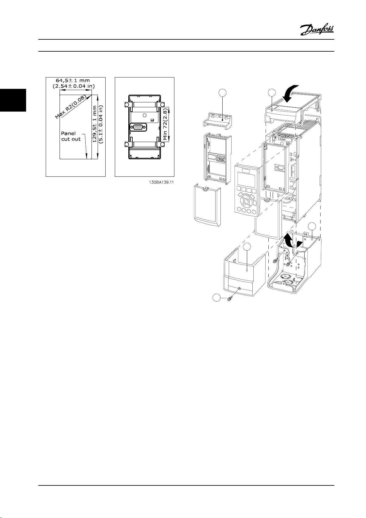
A
B
C
D
E
130BT323.10
Selection Design Guide
3.1.14
IP21/Type 1 Enclosure Kit
33
Figure 3.18 Dimensions
3.1.13
IP21/IP41 top/ TYPE 1 is an optional enclosure element
available for IP20 compact units, enclosure size A2-A3,
B3+B4 and C3+C4.
If the enclosure kit is used, an IP20 unit is upgraded to
comply with enclosure IP21/41 top/TYPE 1.
IP21/IP41/ TYPE1 Enclosure Kit
The IP41 top can be applied to all standard IP20 VLT
HVAC Drive variants.
®
Figure 3.19 Enclosure Type A2
70 Danfoss A/S © Rev. 06/2014 All rights reserved. MG11BC22
Page 73
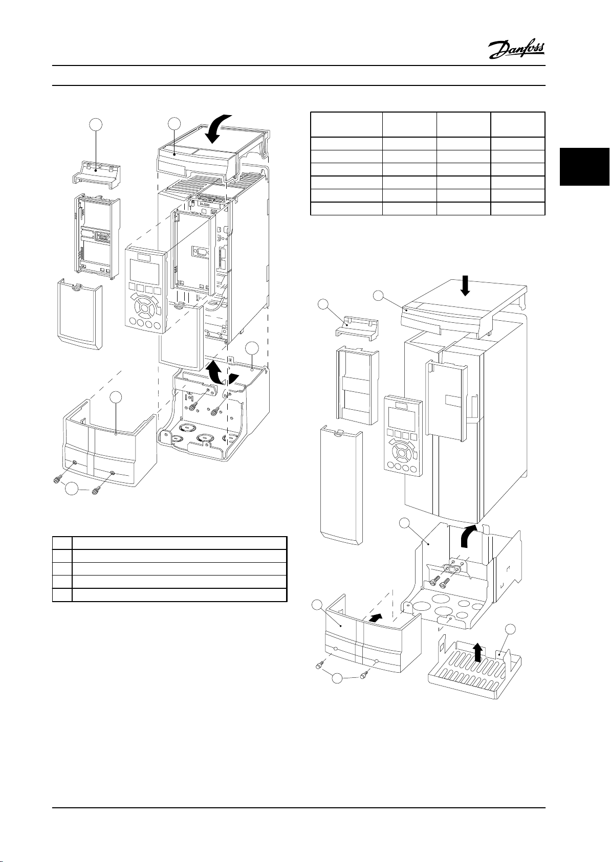
B
A
E
C
D
130BT324.10
E
F
D
C
B
A
130BT620.12
Selection Design Guide
Enclosure type
A2 14.65 [372] 3.54 [90] 8.07 [205]
A3 14.65 [372] 5.12 [130] 8.07 [205]
B3 18.7 [475] 6.5 [165] 9.8 [249]
B4 26.38 [670] 10.04 [255] 9.69 [246]
C3 29.72 [755] 12.95 [329] 13.27 [337]
C4 37.4 [950] 15.39 [391] 13.27 [337]
Table 3.13 Dimensions
* If option A/B is used, the depth increases
(see chapter 5.1.2 Mechanical Dimensions for details)
Height A
(in [mm])
Width B
(in [mm])
Depth C*
(in [mm])
3 3
Figure 3.20 Enclosure Type A3
Top cover
A
B Brim
C Base part
D Base cover
E Screw(s)
Table 3.12 Legend to Figure 3.19 and Figure 3.20
Place the top cover as shown. If an A or B option is used,
the brim must be fitted to cover the top inlet. Place the
base part C at the bottom of the adjustable frequency
drive and use the clamps from the accessory bag to
correctly fasten the cables. Holes for cable connectors:
Size A2: 2x M25 and 3xM32
Size A3: 3xM25 and 3xM32
Figure 3.21 Enclosure Type B3
MG11BC22 Danfoss A/S © Rev. 06/2014 All rights reserved. 71
Page 74
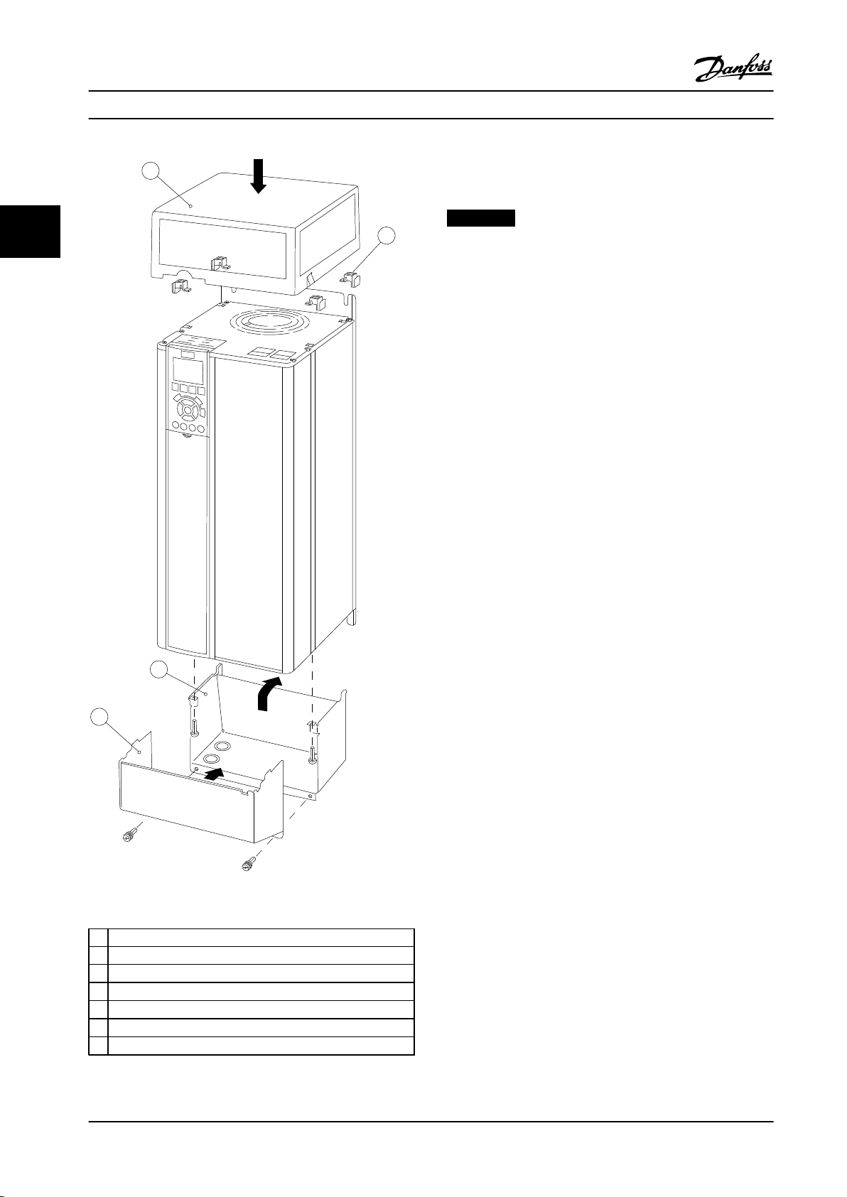
130BT621.12
D
C
A
G
Selection
Design Guide
When option module A and/or option module B is/are
used, the brim (B) must be fitted to the top cover (A).
NOTICE!
33
Side-by-side installation is not possible when using the
IP21/IP4X/TYPE 1 Enclosure Kit.
3.1.15 Output Filters
The high speed switching of the adjustable frequency
drive produces some secondary effects, which influence
the motor and the enclosed environment. These side
effects are addressed by two different filter types, the
dU/dt and the sine-wave filter.
dU/dt filters
Motor insulation stresses are often caused by the
combination of rapid voltage and current increase. The
rapid energy changes can also be reflected back to the DC
line in the inverter and cause shutdown. The dU/dt filter is
designed to reduce the voltage rise time/the rapid energy
change in the motor and by that intervention avoid
premature aging and flashover in the motor insulation.
dU/dt filters have a positive influence on the radiation of
magnetic noise in the cable that connects the adjustable
frequency drive to the motor. The voltage wave form is
still pulse shaped but the dU/dt ratio is reduced in
comparison with the installation without filter.
Sine-wave filters
Sine-wave filters are designed to allow only low
frequencies to pass. High frequencies are consequently
shunted away, which results in a sinusoidal phase-to-phase
voltage waveform and sinusoidal current waveforms.
With the sinusoidal waveforms, the use of special
adjustable frequency drive motors with reinforced
insulation is no longer needed. The acoustic noise from the
motor is also damped as a consequence of the wave
condition.
Besides the features of the dU/dt filter, the sine-wave filter
also reduces insulation stress and bearing currents in the
Figure 3.22 Enclosure Types B4 - C3 - C4
motor thus leading to prolonged motor lifetime and longer
periods between services. Sine-wave filters enable use of
longer motor cables in applications where the motor is
Top cover
A
B Brim
C Base part
D Base cover
E Screw(s)
F Fan cover
G Top clip
Table 3.14 Legend to Figure 3.21 and Figure 3.21
installed far from the adjustable frequency drive. The
length is unfortunately limited because the filter does not
reduce leakage currents in the cables.
72 Danfoss A/S © Rev. 06/2014 All rights reserved. MG11BC22
Page 75
How to Order Design Guide
4 How to Order
4.1 Ordering Form
4.1.1 Drive Configurator
It is possible to design an adjustable frequency drive
according to the application requirements by using the
ordering number system.
Order the adjustable frequency drive as either standard or
with integral options by sending a type code string
describing the product a to the local Danfoss sales office,
i.e.:
FC-102P18KT4E21H1XGCXXXSXXXXAGBKCXXXXDX
The meaning of the characters in the string can be located
in the pages containing the ordering numbers in chapter 3
Selection. In the example above, a Profibus LON works
option and a general purpose I/O option is included in the
adjustable frequency drive.
Ordering numbers for adjustable frequency drive standard
variants can also be located in chapter 4 How to Order.
Configure the right adjustable frequency drive for the right
application and generate the type code string in the
Internet-based Drive Configurator. The Drive Configurator
automatically generates an 8-digit sales number to be
delivered to the local sales office.
Furthermore, establish a project list with several products
and send it to a Danfoss sales representative.
Example of Drive Configurator interface set-up:
The numbers shown in the boxes refer to the letter/figure
number of the type code string; read from left to right.
Product groups 1-3
Adjustable frequency drive series 4-6
Power rating 8-10
Phases 11
AC Line Voltage 12
Enclosure 13-15
Enclosure type
Enclosure class
Control supply voltage
Hardware configuration
RFI filter 16-17
Brake 18
Display (LCP) 19
Coating PCB 20
Line power option 21
Adaptation A 22
Adaptation B 23
Software release 24-27
Software language 28
A options 29-30
B options 31-32
C0 options, MCO 33-34
C1 options 35
C option software 36-37
D options 38-39
Table 4.1 Example of Drive Configurator Interface Set-up
4 4
The Drive Configurator can be found on the global
Internet site: www.danfoss.com/drives.
MG11BC22 Danfoss A/S © Rev. 06/2014 All rights reserved. 73
Page 76
F C - P T H
130BA052.14
X S A B CX X X X
1 2 3 4 5 6 7 8 9 10 11 12 13 14 15 16 17 18 19 20 302221 23 272524 26 28 29 31 373635343332 38 39
X0 D
How to Order Design Guide
4.1.2 Type Code String Low and Medium Power
Figure 4.1 Type Code String
44
Description Pos. Possible choice
Product group & FC Series 1-6 FC 102
Power rating 8-10 1.1–90 kW (P1K1–P90K)
Number of phases 11 3 phases (T)
S 2: 220–240 V AC single phase
T 2: 200–240 V AC
AC line voltage 11-12
Enclosure 13-15
RFI filter 16-17
Brake 18
Display 19
Coating PCB 20
Line power option 21
Adaptation 22
Adaptation 23 Reserved
Software release 24-27 Current software
Software language 28
T 4: 380–480 V AC
T 6: 525–600 V AC
T 7: 525–690 V AC
E20: IP20
E21: IP21/NEMA Type 1
E55: IP55/NEMA Type 12
E66: IP66
P21: IP21/NEMA Type 1 w/backplate
P55: IP55/NEMA Type 12 w/backplate
Z55: A4 Frame IP55
Z66: A4 Frame IP66
H1: RFI filter class A1/B
H2: RFI filter class A2
H3: RFI filter class A1/B (reduced cable length)
Hx: No RFI filter
X: No brake chopper included
B: Brake chopper included
T: Safe Stop
U: Safe + brake
G: Graphical Local Control Panel (GLCP)
N: Numeric Local Control Panel (NLCP)
X: No Local Control Panel
X. No coated PCB
C: Coated PCB
X: No line power disconnect switch and load sharing
1: With line power disconnect switch (IP55 only)
8: Line power disconnect and Load Sharing
D: Load Sharing
See Chapter 9 for max. cable sizes.
X: Standard cable entries
O: European metric thread in cable entries (A4, A5, B1, B2 only)
S: Imperial cable entries (A5, B1, B2 only)
74 Danfoss A/S © Rev. 06/2014 All rights reserved. MG11BC22
Page 77
How to Order Design Guide
Description Pos. Possible choice
AX: No options
A0: MCA 101 Profibus DP V1
A4: MCA 104 DeviceNet
A options 29-30
B options 31-32
C0 options MCO 33-34 CX: No options
C1 options 35 X: No options
C option software 36-37 XX: Standard software
D options 38-39
AG: MCA 108 Lonworks
AJ: MCA 109 BACnet gateway
AL: MCA 120 Profinet
AN: MCA 121 EtherNet/IP
AQ: MCA 122 Modbus TCP
BX: No option
BK: MCB 101 General purpose I/O option
BP: MCB 105 Relay option
BO: MCB 109 Analog I/O option
B2: MCB 112 PTC Thermistor Card
B4: MCB 114 Sensor input option
DX: No option
D0: 24 V backup
4 4
Table 4.2 Type Code Description
4.2 Ordering Numbers
4.2.1 Ordering Numbers: Options and Accessories
Type Description Ordering no.
Miscellaneous hardware I
DC link connector Terminal block for DC link connnection on A2/A3 130B1064
IP 21/4X top/TYPE 1 kit IP21/NEMA1 Top + bottom A2 130B1122
IP 21/4X top/TYPE 1 kit IP21/NEMA1 Top + bottom A3 130B1123
IP 21/4X top/TYPE 1 kit IP21/NEMA1 Top + bottom B3 130B1187
IP 21/4X top/TYPE 1 kit IP21/NEMA1 Top + bottom B4 130B1189
IP 21/4X top/TYPE 1 kit IP21/NEMA1 Top + bottom C3 130B1191
IP 21/4X top/TYPE 1 kit IP21/NEMA1 Top + bottom C4 130B1193
IP21/4X top IP21 Top Cover A2 130B1132
IP21/4X top IP21 Top Cover A3 130B1133
IP 21/4X top IP21 Top Cover B3 130B1188
IP 21/4X top IP21 Top Cover B4 130B1190
IP 21/4X top IP21 Top Cover C3 130B1192
IP 21/4X top IP21 Top Cover C4 130B1194
Panel Through Mount Kit Enclosure, enclosure type A5 130B1028
Panel Through Mount Kit Enclosure, enclosure type B1 130B1046
Panel Through Mount Kit Enclosure, enclosure type B2 130B1047
Panel Through Mount Kit Enclosure, enclosure type C1 130B1048
Panel Through Mount Kit Enclosure, enclosure type C2 130B1049
Profibus D-Sub 9 Connector kit for IP20 130B1112
Profibus top entry kit Top entry kit for Profibus connection - D + E enclosure types 176F1742
Terminal blocks Screw terminal blocks for replacing spring loaded terminals
1 x 10-pin, 1 x 6-pin and 1 x 3-pin connectors
Backplate A5 IP55/NEMA 12 130B1098
Backplate B1 IP21/IP55 / NEMA 12
130B1116
130B3383
MG11BC22 Danfoss A/S © Rev. 06/2014 All rights reserved. 75
Page 78
How to Order
Type Description Ordering no.
Miscellaneous hardware I
Backplate B2 IP21/IP55 / NEMA 12 130B3397
Backplate C1 IP21/IP55 / NEMA 12 130B3910
Backplate C2 IP21/IP55 / NEMA 12 130B3911
Backplate A5 IP66 130B3242
Backplate B1 IP66 130B3434
44
Backplate B2 IP66 130B3465
Backplate C1 IP66 130B3468
Backplate C2 IP66 130B3491
LCPs and kits
LCP 101 Numerical Local Control Panel (NLCP) 130B1124
102 Graphical Local Control Panel (GLCP) 130B1107
cable Separate cable, 10 ft [3 m] 175Z0929
kit Panel mounting kit including graphical LCP, fasteners, 10 ft [3 m] cable and
gasket
LCP kit Panel mounting kit including numerical LCP, fasteners and gasket 130B1114
kit Panel mounting kit for all LCPs including fasteners, 10 ft [3 m] cable and
gasket
kit Front mounting kit, IP55 enclosures 130B1129
kit Panel mounting kit for all LCPs including fasteners and gasket - without
cable
Design Guide
130B1113
130B1117
130B1170
Table 4.3 Options can be ordered as factory built-in options, see ordering information.
Type Description Comments
Options for Slot A Ordering no.
Coated
MCA 101 Profibus option DP V0/V1 130B1200
MCA 104 DeviceNet option 130B1202
MCA 108 Lonworks 130B1206
MCA 109 BACnet gateway for built-in. Not to be used with the relay option MCB 105 card 130B1244
MCA 120 Profinet 130B1135
MCA 121 Ethernet 130B1219
Options for Slot B
MCB 101 General purpose Input Output option
MCB 105 Relay option
MCB 109 Analog I/O option and battery backup for real-time clock 130B1243
MCB 112 ATEX PTC 130B1137
MCB 114
Option for Slot D
MCB 107 24 V DC backup 130B1208
External Options
Ethernet IP Ethernet master
Table 4.4 Ordering Information Options
For information on serial communication bus and application option compatibility with older software versions, contact your Danfoss supplier.
Sensor input - uncoated 130B1172
Sensor input - coated 130B1272
76 Danfoss A/S © Rev. 06/2014 All rights reserved. MG11BC22
Page 79
How to Order Design Guide
Type Description
Spare Parts Ordering no. Comments
Control board FC With Safe Stop Function 130B1150
Control board FC Without Safe Stop Function 130B1151
Fan A2 Fan, enclosure type A2 130B1009
Fan A3 Fan, enclosure type A3 130B1010
Fan A5 Fan, enclosure type A5 130B1017
Fan B1 Fan external, enclosure type B1 130B3407
Fan B2 Fan external, enclosure type B2 130B3406
Fan B3 Fan external, enclosure type B3 130B3563
Fan B4 Fan external, 18.5/22 kW 130B3699
Fan B4 Fan external 22/30 kW 130B3701
Fan C1 Fan external, enclosure type C1 130B3865
Fan C2 Fan external, enclosure type C2 130B3867
Fan C3 Fan external, enclosure type C3 130B4292
Fan C4 Fan external, enclosure type C4 130B4294
Miscellaneous hardware II
Accessory bag A2 Accessory bag, enclosure type A2 130B1022
Accessory bag A3 Accessory bag, enclosure type A3 130B1022
Accessory bag A4 Accessory bag for frame A4 w/o thread 130B0536
Accessory bag A5 Accessory bag, enclosure type A5 130B1023
Accessory bag B1 Accessory bag, enclosure type B1 130B2060
Accessory bag B2 Accessory bag, enclosure type B2 130B2061
Accessory bag B3 Accessory bag, enclosure type B3 130B0980
Accessory bag B4 Accessory bag, enclosure type B4 130B1300 Small
Accessory bag B4 Accessory bag, enclosure type B4 130B1301 Big
Accessory bag C1 Accessory bag, enclosure type C1 130B0046
Accessory bag C2 Accessory bag, enclosure type C2 130B0047
Accessory bag C3 Accessory bag, enclosure type C3 130B0981
Accessory bag C4 Accessory bag, enclosure type C4 130B0982 Small
Accessory bag C4 Accessory bag, enclosure type C4 130B0983 Big
4 4
Table 4.5 Accessories Ordering Information
MG11BC22 Danfoss A/S © Rev. 06/2014 All rights reserved. 77
Page 80
How to Order Design Guide
4.2.2 Ordering Numbers: Harmonic Filters
Harmonic filters are used to reduce line harmonics.
AHF 010: 10% current distortion
•
AHF 005: 5% current distortion
•
44
I
[A] Typical Motor Used [kW] Danfoss Ordering Number Adjustable frequency
AHF, N
AHF 005 AHF 010
10 1.1–4 175G6600 175G6622 P1K1, P4K0
19 5.5–7.5 175G6601 175G6623 P5K5–P7K5
26 11 175G6602 175G6624 P11K
35 15–18.5 175G6603 175G6625 P15K–P18K
43 22 175G6604 175G6626 P22K
72 30–37 175G6605 175G6627 P30K–P37K
101 45–55 175G6606 175G6628 P45K–P55K
144 75 175G6607 175G6629 P75K
180 90 175G6608 175G6630 P90K
217 110 175G6609 175G6631 P110
289 132 175G6610 175G6632 P132–P160
324 160 175G6611 175G6633
370 200 175G6688 175G6691 P200
506 250
578 315 2x 175G6610 2x 175G6632 P315
648 355 2x175G6611 2x175G6633 P355
694 400
740 450 2x175G6688 2x175G6691 P450
175G6609
+ 175G6610
175G6611
+ 175G6688
175G6631
+ 175G6632
175G6633
+ 175G6691
drive size
P250
P400
Table 4.6 380–415 V AC, 50 Hz
78 Danfoss A/S © Rev. 06/2014 All rights reserved. MG11BC22
Page 81
How to Order
I
[A] Typical Motor Used [hp] Danfoss Ordering Number Adjustable frequency drive
AHF, N
10 1.1–4 130B2540 130B2541 P1K1–P4K0
19 5.5–7.5 130B2460 130B2472 P5K5–P7K5
26 11 130B2461 130B2473 P11K
35 15–18.5 130B2462 130B2474 P15K, P18K
43 22 130B2463 130B2475 P22K
72 30–37 130B2464 130B2476 P30K–P37K
101 45–55 130B2465 130B2477 P45K–P55K
144 75 130B2466 130B2478 P75K
180 90 130B2467 130B2479 P90K
217 110 130B2468 130B2480 P110
289 132 130B2469 130B2481 P132
324 160 130B2470 130B2482 P160
370 200 130B2471 130B2483 P200
506 250
578 315 2x 130B2469 2x 130B2481 P315
648 355 2x130B2470 2x130B2482 P355
694 400
740 450 2x130B2471 130B2483 P450
Design Guide
AHF 005 AHF 010
130B2468
+ 130B2469
130B2470
+ 130B2471
130B2480
+ 130B2481
130B2482
+ 130B2483
size
4 4
P250
P400
Table 4.7 380–415 V AC, 60 Hz
I
[A] Typical Motor Used [hp] Danfoss Ordering Number Adjustable frequency drive
AHF, N
AHF 005 AHF 010
10 1.5–7.5 130B2538 130B2539 P1K1–P5K5
19 10–15 175G6612 175G6634 P7K5–P11K
26 20 175G6613 175G6635 P15K
35 25–30 175G6614 175G6636 P18K–P22K
43 40 175G6615 175G6637 P30K
72 50–60 175G6616 175G6638 P37K–P45K
101 75 175G6617 175G6639 P55K
144 100–125 175G6618 175G6640 P75K–P90K
180 150 175G6619 175G6641 P110
217 200 175G6620 175G6642 P132
289 250 175G6621 175G6643 P160
370 350 175G6690 175G6693 P200
434 350 2x175G6620 2x175G6642 P250
506 450 175G6620 + 175G6621 175G6642 + 175G6643 P315
578 500 2x 175G6621 2x 175G6643 P355
648 550-600 2x175G6689 2x175G6692 P400
694 600 175G6689 + 175G6690 175G6692 + 175G6693 P450
740 650 2x175G6690 2x175G6693 P500
Table 4.8 440–480 V AC, 60 Hz
size
Matching the adjustable frequency drive and filter is pre-calculated based on 400 V/480 V, a typical motor load (4-pole) and
110% torque.
MG11BC22 Danfoss A/S © Rev. 06/2014 All rights reserved. 79
Page 82
How to Order Design Guide
I
[A] Typical Motor Used [kW] Danfoss Ordering Number Adjustable frequency
AHF, N
AHF 005 AHF 010
10 1.1–7.5 175G6644 175G6656 P1K1–P7K5
19 11 175G6645 175G6657 P11K
26 15–18.5 175G6646 175G6658 P15K–P18K
35 22 175G6647 175G6659 P22K
43 30 175G6648 175G6660 P30K
44
72 37–45 175G6649 175G6661 P45K–P55K
101 55 175G6650 175G6662 P75K
144 75-90 175G6651 175G6663 P90K–P110
180 110 175G6652 175G6664 P132
217 132 175G6653 175G6665 P160
289 160–200 175G6654 175G6666 P200–P250
324 250 175G6655 175G6667 P315
397 315 175G6652 + 175G6653 175G6641 + 175G6665 P400
434 355 2x175G6653 2x175G6665 P450
506 400 175G6653 + 175G6654 175G6665 + 175G6666 P500
578 450 2X 175G6654 2X 175G6666 P560
613 500 175G6654 + 175G6655 175G6666 + 175G6667 P630
drive size
Table 4.9 500–525 V AC, 50 Hz
I
[A] Typical Motor Used [kW] Danfoss Ordering Number Adjustable frequency drive
AHF, N
AHF 005 AHF 010
43 45 130B2328 130B2293
72 45–55 130B2330 130B2295 P37K–P45K
101 75-90 130B2331 130B2296 P55K–P75K
144 110 130B2333 130B2298 P90K–P110
180 132 130B2334 130B2299 P132
217 160 130B2335 130B2300 P160
288 200–250 2x130B2333 130B2301 P200–P250
324 315 130B2334 + 130B2335 130B2302 P315
397 400 130B2334 + 130B2335 130B2299 + 130B2300 P400
434 450 2x130B2335 2x130B2300 P450
505 500 * 130B2300 + 130B2301 P500
576 560 * 2x130B2301 P560
612 630 * 130B2301 + 130B2300 P630
730 710 * 2x130B2302 P710
Table 4.10 690 V AC, 50 Hz
* For higher currents, contact Danfoss.
size
80 Danfoss A/S © Rev. 06/2014 All rights reserved. MG11BC22
Page 83
How to Order Design Guide
4.2.3 Ordering Numbers: Sine-Wave Filter Modules, 200–500 V AC
Adj. Frequency Drive Size
200–240
[V AC]
P1K1 P1K1 5 120 130B2441 130B2406 4.5
P1K5 P1K5 5 120 130B2441 130B2406 4.5
P1K5 P3K0 P3K0 5 120 130B2443 130B2408 8
P4K0 P4K0 5 120 130B2444 130B2409 10
P2K2 P5K5 P5K5 5 120 130B2446 130B2411 17
P3K0 P7K5 P7K5 5 120 130B2446 130B2411 17
P4K0 5 120 130B2446 130B2411 17
P5K5 P11K P11K 4 100 130B2447 130B2412 24
P7K5 P15K P15K 4 100 130B2448 130B2413 38
P18K P18K 4 100 130B2448 130B2413 38
P11K P22K P22K 4 100 130B2307 130B2281 48
P15K P30K P30K 3 100 130B2308 130B2282 62
P18K P37K P37K 3 100 130B2309 130B2283 75
P22K P45K P55K 3 100 130B2310 130B2284 115
P30K P55K P75K 3 100 130B2310 130B2284 115
P37K P75K P90K 3 100 130B2311 130B2285 180
P45K P90K P110 3 100 130B2311 130B2285 180
P110 P132 3 100 130B2312 130B2286 260
P132 P160 3 100 130B2313 130B2287 260
P160 P200 3 100 130B2313 130B2287 410
P200 P250 3 100 130B2314 130B2288 410
P250 P315 3 100 130B2314 130B2288 480
P315 P315 2 100 130B2315 130B2289 660
P355 P355 2 100 130B2315 130B2289 660
P400 P400 2 100 130B2316 130B2290 750
P450 2 100 130B2316 130B2290 750
P450 P500 2 100 130B2317 130B2291 880
P500 P560 2 100 130B2317 130B2291 880
P560 P630 2 100 130B2318 130B2292 1200
P630 P710 2 100 130B2318 130B2292 1200
P710 P800 2 100 2x130B2317 2x130B2291 1500
P800 P1M0 2 100 2x130B2317 2x130B2291 1500
P1M0 2 100 2x130B2318 2x130B2292 1700
380–440
[V AC]
P2K2 P2K2 5 120 130B2443 130B2408 8
440–480
[V AC]
Minimum switching
frequency [kHz]
Maximum
output
frequency [Hz]
Part No. IP20 Part No. IP00
Rated filter current
at 50 Hz [A]
4 4
Table 4.11 Line Power Supply 3x200 to 480 V AC
When using sine-wave filters, the switching frequency should comply with filter specifications in 14-01 Switching Frequency.
NOTICE!
See also Output Filter Design Guide.
MG11BC22 Danfoss A/S © Rev. 06/2014 All rights reserved. 81
Page 84
How to Order Design Guide
4.2.4 Ordering Numbers: Sine-Wave Filter Modules, 525–600/690 V AC
Adj. Frequency Drive Size
525–600 [V AC] 690 [V AC]
P1K1 2 100 130B2341 130B2321 13
P1K5 2 100 130B2341 130B2321 13
44
P2k2 2 100 130B2341 130B2321 13
P3K0 2 100 130B2341 130B2321 13
P4K0 2 100 130B2341 130B2321 13
P5K5 2 100 130B2341 130B2321 13
P7K5 2 100 130B2341 130B2321 13
P11K 2 100 130B2342 130B2322 28
P15K 2 100 130B2342 130B2322 28
P18K 2 100 130B2342 130B2322 28
P22K 2 100 130B2342 130B2322 28
P30K 2 100 130B2343 130B2323 45
P37K P45K 2 100 130B2344 130B2324 76
P45K P55K 2 100 130B2344 130B2324 76
P55K P75K 2 100 130B2345 130B2325 115
P75K P90K 2 100 130B2345 130B2325 115
P90K P110 2 100 130B2346 130B2326 165
P132 2 100 130B2346 130B2326 165
P160 2 100 130B2347 130B2327 260
P200 2 100 130B2347 130B2327 260
P250 2 100 130B2348 130B2329 303
P315 2 100 130B2370 130B2341 430
P355 1.5 100 130B2370 130B2341 430
P400 1.5 100 130B2370 130B2341 430
P450 1.5 100 130B2371 130B2342 530
P500 1.5 100 130B2371 130B2342 530
P560 1.5 100 130B2381 130B2337 660
P630 1.5 100 130B2381 130B2337 660
P710 1.5 100 130B2382 130B2338 765
P800 1.5 100 130B2383 130B2339 940
P900 1.5 100 130B2383 130B2339 940
P1M0 1.5 100 130B2384 130B2340 1320
P1M2 1.5 100 130B2384 130B2340 1320
P1M4 1.5 100 2x130B2382 2x130B2338 1479
Minimum switching
frequency [kHz]
Maximum output
frequency [Hz]
Part No. IP20 Part No. IP00
Rated filter
current at
50 Hz [A]
Table 4.12 Line Power Supply 3 x 525–690 V AC
NOTICE!
When using sine-wave filters, the switching frequency should comply with filter specifications in 14-01 Switching
Frequency.
NOTICE!
See also Output Filter Design Guide.
82 Danfoss A/S © Rev. 06/2014 All rights reserved. MG11BC22
Page 85
How to Order Design Guide
4.2.5 Ordering Numbers: dU/dt Filters, 380–480 V AC
Adj. Frequency Drive Size
380–439 [V AC] 440–480 [V AC]
P11K P11K 4 100 130B2396 130B2385 24
P15K P15K 4 100 130B2397 130B2386 45
P18K P18K 4 100 130B2397 130B2386 45
P22K P22K 4 100 130B2397 130B2386 45
P30K P30K 3 100 130B2398 130B2387 75
P37K P37K 3 100 130B2398 130B2387 75
P45K P45K 3 100 130B2399 130B2388 110
P55K P55K 3 100 130B2399 130B2388 110
P75K P75K 3 100 130B2400 130B2389 182
P90K P90K 3 100 130B2400 130B2389 182
P110 P110 3 100 130B2401 130B2390 280
P132 P132 3 100 130B2401 130B2390 280
P160 P160 3 100 130B2402 130B2391 400
P200 P200 3 100 130B2402 130B2391 400
P250 P250 3 100 130B2277 130B2275 500
P315 P315 2 100 130B2278 130B2276 750
P355 P355 2 100 130B2278 130B2276 750
P400 P400 2 100 130B2278 130B2276 750
P450 2 100 130B2278 130B2276 750
P450 P500 2 100 130B2405 130B2393 910
P500 P560 2 100 130B2405 130B2393 910
P560 P630 2 100 130B2407 130B2394 1500
P630 P710 2 100 130B2407 130B2394 1500
P710 P800 2 100 130B2407 130B2394 1500
P800 P1M0 2 100 130B2407 130B2394 1500
P1M0 2 100 130B2410 130B2395 2300
Minimum switching
frequency [kHz]
Maximum output
frequency [Hz]
Part No. IP20 Part No. IP00
Rated filter current at
50 Hz [A]
4 4
Table 4.13 Line Power supply 3x380 to 3x480 V AC
NOTICE!
See also Output Filter Design Guide.
MG11BC22 Danfoss A/S © Rev. 06/2014 All rights reserved. 83
Page 86
How to Order Design Guide
4.2.6 Ordering Numbers: dU/dt Filters, 525–600/690 V AC
Adj. Frequency Drive Size
525–600 [V AC] 690 [V AC]
P1K1 4 100 130B2423 130B2414 28
P1K5 4 100 130B2423 130B2414 28
P2K2 4 100 130B2423 130B2414 28
44
P3K0 4 100 130B2423 130B2414 28
P4K0 4 100 130B2424 130B2415 45
P5K5 4 100 130B2424 130B2415 45
P7K5 3 100 130B2425 130B2416 75
P11K 3 100 130B2425 130B2416 75
P15K 3 100 130B2426 130B2417 115
P18K 3 100 130B2426 130B2417 115
P22K 3 100 130B2427 130B2418 165
P30K 3 100 130B2427 130B2418 165
P37K P45K 3 100 130B2425 130B2416 75
P45K P55K 3 100 130B2425 130B2416 75
P55K P75K 3 100 130B2426 130B2417 115
P75K P90K 3 100 130B2426 130B2417 115
P90K P110 3 100 130B2427 130B2418 165
P132 2 100 130B2427 130B2418 165
P160 2 100 130B2428 130B2419 260
P200 2 100 130B2428 130B2419 260
P250 2 100 130B2429 130B2420 310
P315 2 100 130B2238 130B2235 430
P400 2 100 130B2238 130B2235 430
P450 2 100 130B2239 130B2236 530
P500 2 100 130B2239 130B2236 530
P560 2 100 130B2274 130B2280 630
P630 2 100 130B2274 130B2280 630
P710 2 100 130B2430 130B2421 765
P800 2 100 130B2431 130B2422 1350
P900 2 100 130B2431 130B2422 1350
P1M0 2 100 130B2431 130B2422 1350
P1M2 2 100 130B2431 130B2422 1350
P1M4 2 100 2x130B2430 2x130B2421 1530
Minimum switching
frequency [kHz]
Maximum output
frequency [Hz]
Part No. IP20 Part No. IP00
Rated filter current at 50
Hz [A]
Table 4.14 Line Power Supply 3x525 to 3x690 V AC
NOTICE!
See also Output Filter Design Guide.
4.2.7 Ordering Numbers: Brake Resistors
NOTICE!
See Brake Resistor Design Guide.
84 Danfoss A/S © Rev. 06/2014 All rights reserved. MG11BC22
Page 87
Mechanical Installation Design Guide
5 Mechanical Installation
5.1 Mechanical Installation
5.1.1 Safety Requirements of Mechanical
Installation
WARNING
Pay attention to the requirements that apply to
integration and the field mounting kit. Observe the
information in the list to avoid serious injury or
equipment damage, especially when installing large
units.
CAUTION
The adjustable frequency drive is cooled by air
circulation.
To protect the unit from overheating, it must be ensured
that the ambient temperature does not exceed the
maximum temperature stated for the adjustable frequency
drive, and that the 24-hour average temperature is not
exceeded. Locate the maximum temperature and 24-hour
average in chapter 9.6.2 Derating for Ambient
Temperature.
If the ambient temperature is in the range of 113–131 °F
[45 °C–55 °C], derating of the adjustable frequency drive
becomes relevant, see chapter 9.6.2 Derating for Ambient
Temperature.
The service life of the adjustable frequency drive is
reduced if derating for ambient temperature is not taken
into account.
5 5
MG11BC22 Danfoss A/S © Rev. 06/2014 All rights reserved. 85
Page 88
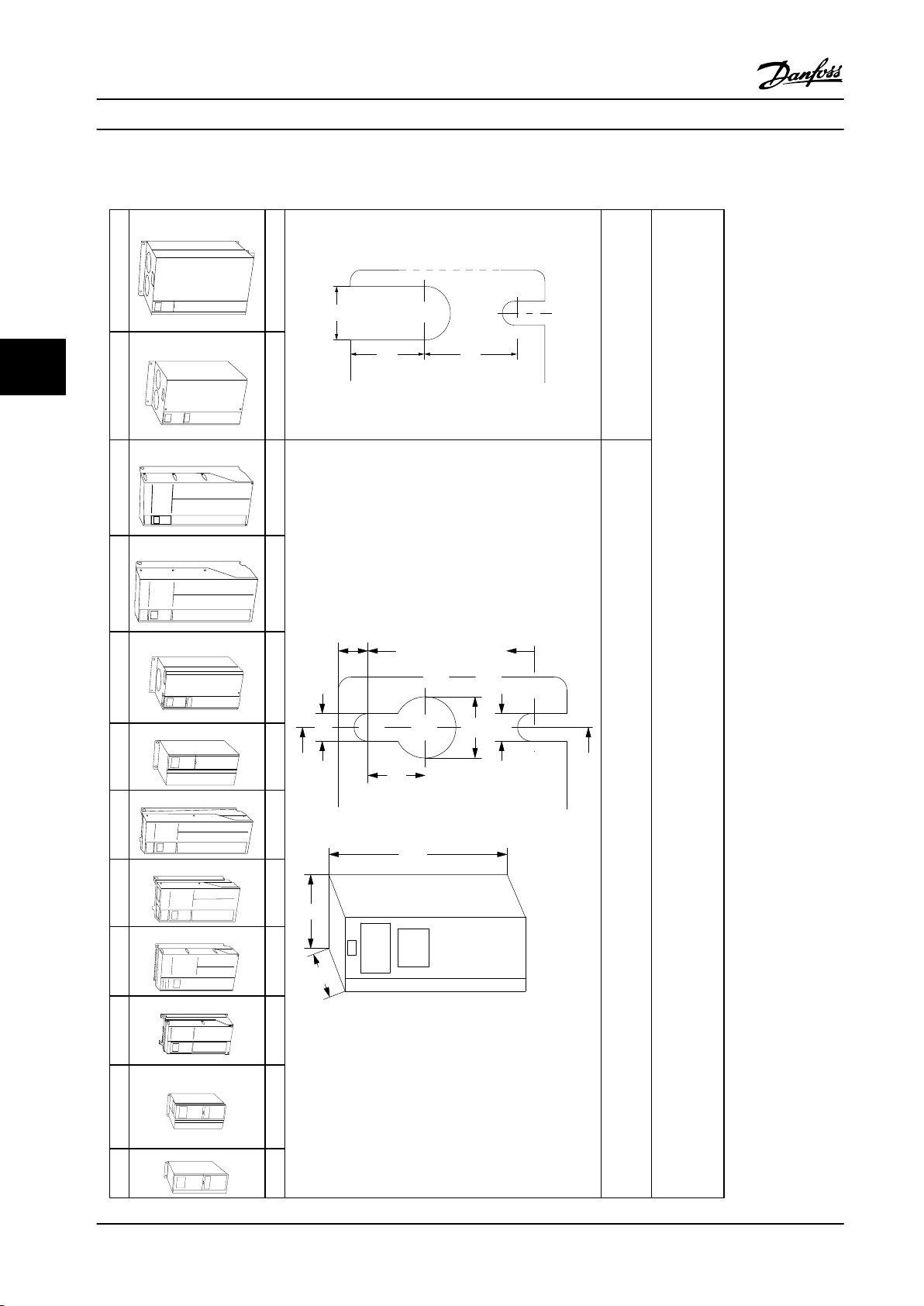
130BA809.10
130BA810.10
130BB458.10
130BA811.10
130BA812.10
130BA813.10
130BA826.10
130BA827.10
130BA814.10
130BA815.10
130BA828.10
130BA829.10
C
a
b
130BA648.12
f
e
B
A
a
d
e
b
c
a
e
f
130BA715.12
Mechanical Installation Design Guide
5.1.2 Mechanical Dimensions
55
(B4, C3 and C4 only)
Top and bottom mounting holes
* A5 in IP55/66 only
A2 A3 A4 A5 B1 B2 B3 B4 C1 C2 C3 C4
IP20/21 IP20/21 IP55/66 IP55/66 IP21/55/66 IP21/55/66 IP20 IP20 IP21/55/66 IP21/55/66 IP20 IP20
86 Danfoss A/S © Rev. 06/2014 All rights reserved. MG11BC22
Accessory bags containing necessary brackets, screws and connectors are included with the adjustable frequency drives upon delivery.
Table 5.1 Mechanical Dimensions
Page 89
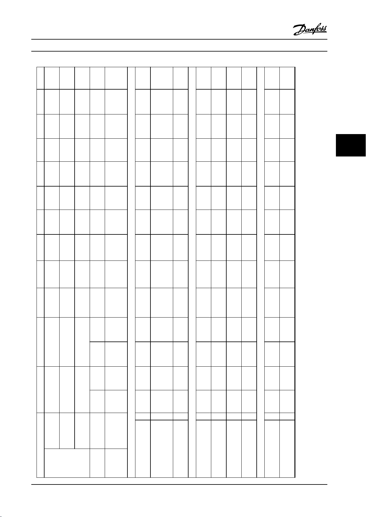
Mechanical Installation Design Guide
50–60
[37–45]
30–40
[22–30]
50–60
[37–45]
25–40
[18–30]
11–25
[15–18]
7.5–15
[5.5–11]
20
[15]
7.5–15
[5.5–11]
[75–90]
100–125
60–75
[45–55]
[75–90]
100–125
50–75
[37–55]
30–50
[22–37]
15–25
[11–18]
30–40
[22–30]
15–25
[11–18]
[75–90]
100–125
60–75
[45–55]
[75–90]
100–125
50–75
[37–55]
30–50
[22–37]
15–25
[11–18]
30–40
[22–30]
15–25
[11–18]
50–125
[37–90]
[11–30]
20
Chassis
20
Chassis
Type 1/
21/55/66
Type 1/
21/55/66
20
Chassis
20
Chassis
Type 1/
21/55/66
Type 1/
21/ 55/66
Type 12
Type 12
Type 12
Type 12
25.98
21.65
30.32
26.77
20.47
15.71
25.59
18.90
[660]
[550]
[770]
[680]
[520]
[399]
[650]
[480]
31.5
24.8
23.43
16.54
[800]
[630]
[595]
[420]
24.84
20.51
29.1
25.51
19.50
14.96
24.57
17.87
[631]
[521]
[739]
[648]
[495]
[380]
[624]
[454]
14.57
12.13
14.57
12.13
9.06
6.5
9.53
9.53
[370]
[308]
[370]
[308]
[230]
[165]
[242]
[242]
14.57
12.13
14.57
12.13
9.06
8.07
9.53
9.53
[370]
[308]
[370]
[308]
[230]
[205]
[242]
[242]
14.57
12.13
14.57
12.13
9.06
8.86
9.53
9.53
[370]
[308]
[370]
[308]
[230]
[225]
[242]
[242]
13
10.63
13.15
10.71
7.87
5.51
8.27
8.27
[330]
[270]
[334]
[272]
[200]
[140]
[210]
[210]
12.99
12.99
13.19
12.21
9.53
9.8
10.24
10.24
[333]
[333]
[335]
[310]
[242]
[249]
[260]
[260]
12.99
12.99
13.19
12.21
9.53
10.32
10.24
10.24
[333]
[333]
[335]
5 5
[310]
[242]
[262]
[260]
[260]
1.5–5
1.5–3
4–5
200–240 V 1.5–3
1.5–10
[1.1–3.7]
1.5–5
[1.1–2.2]
7.5–10
[3–3.7]
1.5–5
[1.1–2.2]
380–480/
1.5–10
[1.1–7.5]
[1.1–4]
[5.5–7.5]
[1.1–4.0]
525–600 V 1.5–10
500 V
[1.1–7.5]
[1.1–7.5]
525–690 V 15–40
55/66
Type 12
55/66
Type 12
21
Type 1
20
Chassis
21
Type 1
20
Chassis
16.54
15.35
14.76
10.6
14.76
10.60
[420]
[390]
[375]
[268]
[375]
[268]
- - - - -
14.72
14.72
A
[374]
[374]
15.83
15.80
13.80
10.12
13.80
10.12
a
[402]
[401]
[350]
[257]
[350]
[257]
9.53
7.87
5.12
5.12
3.54
3.54
[242]
[200]
[130]
[130]
[90]
[90]
9.53
6.69
6.69
5.12
5.12
B
[242]
[170]
[170]
[130]
[130]
9.53
7.48
7.48
5.91
5.91
B
[242]
[190]
[190]
[150]
[150]
8.47
6.73
4.33
4.33
2.76
2.76
b
[215]
[171]
[110]
[110]
[70]
[70]
7.87
6.89
18.15
8.07
18.15
8.07
C
[200]
[175]
[207]
[205]
[207]
[205]
7.87
6.89
8.74
8.66
8.74
8.66
[200]
[175]
[222]
[220]
[222]
[220]
Depth without
option A/B
With option A/B C
Height (in [mm])
IP
Enclosure Type A2 A3 A4 A5 B1 B2 B3 B4 C1 C2 C3 C4
Rated
Power
(hp [kW])
MG11BC22 Danfoss A/S © Rev. 06/2014 All rights reserved. 87
NEMA
Height of backplate A
Height with decoupling
plate for serial communi-
cation bus cables
Distance between
mounting holes
Width (in [mm])
Width of backplate B
Width of backplate with
Width of backplate with
one C option
two C options
mounting holes
Depth (in [mm])
Distance between
Page 90
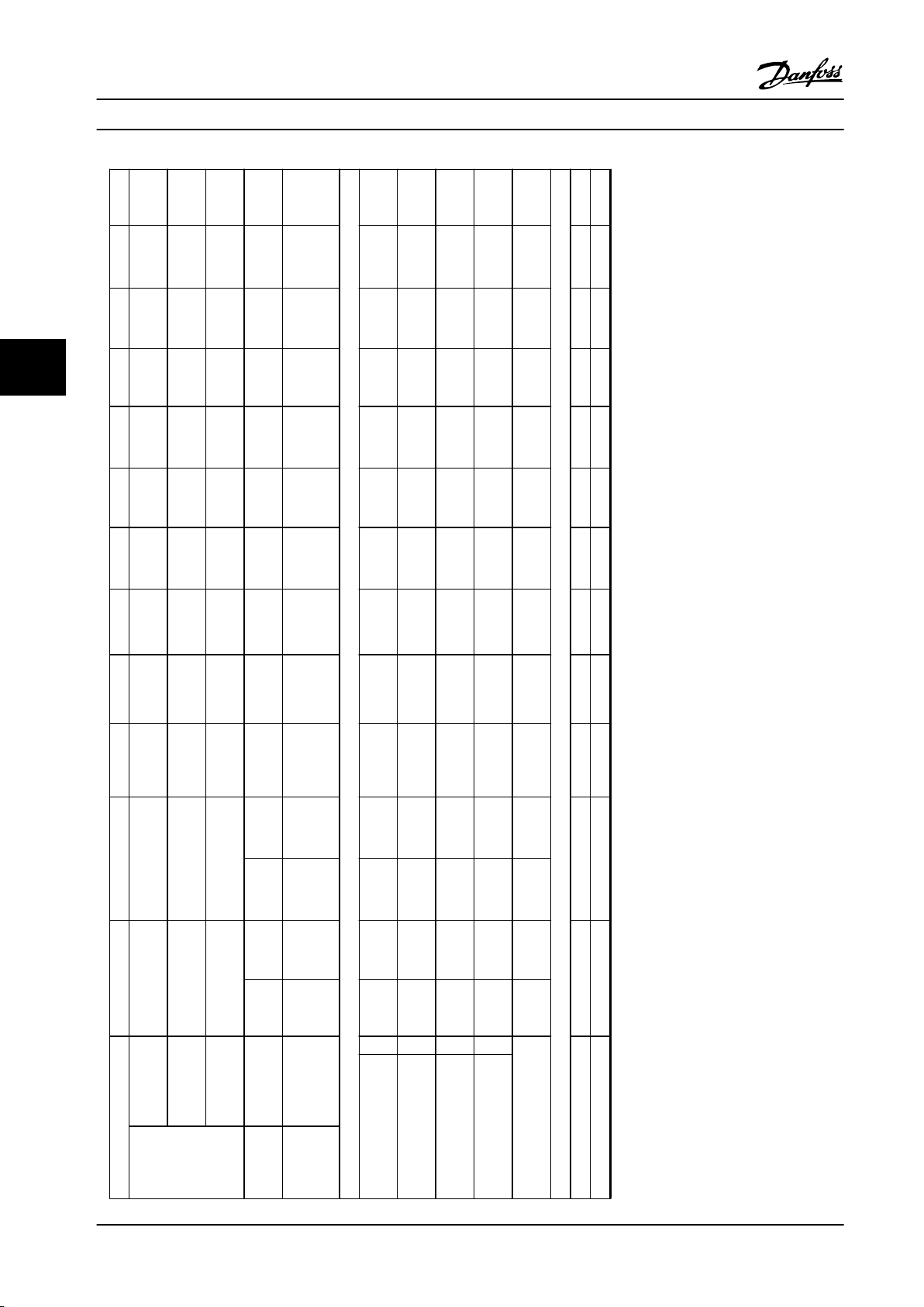
Mechanical Installation Design Guide
50–125
[37–90]
[11–30]
20
Chassis
20
Chassis
Type 1/
21/55/66
Type 1/
21/55/66
20
Chassis
20
Chassis
Type 1/
21/55/66
Type 1/
21/ 55/66
Type 12
Type 12
Type 12
Type 12
0.49
0.49
0.47
0.47
[12.5]
[12.5]
8
[12]
[12]
50–60
30–40
50–60
[37–45]
100–125
60–75
[22–30]
[37–45]
100–125
[75–90]
100–125
60–75
[45–55]
[75–90]
100–125
[75–90]
[45–55]
[75–90]
55
50–75
25–40
[18–30]
11–25
[15–18]
7.5–15
[5.5–11]
20
[15]
7.5–15
[5.5–11]
[37–55]
30–50
[22–37]
15–25
[11–18]
30–40
[22–30]
15–25
[11–18]
50–75
[37–55]
30–50
[22–37]
15–25
[11–18]
30–40
[22–30]
15–25
[11–18]
ø0.75
ø0.75
0.47
ø0.75
ø0.75
[ø19]
[ø19]
[12]
[ø19]
[ø19]
0.34
0.34
ø0.35
ø0.35
0.34
0.27
ø0.35
ø0.35
[8.5]
[8.5]
[ø9]
[ø9]
[8.5]
[6.8]
[ø9]
[ø9]
0.67
0.67
0.39
0.39
0.59
0.31
0.35
0.35
[17]
[17]
[9.8]
[9.8]
[15]
[7.9]
[9]
[9]
110.2
77.2
143.3
99.21
52
26.5
59.53
50.7
[50]
[35]
[65]
[45]
[23.5]
[12]
[27]
[23]
1.5–5
1.5–3
4–5
200–240 V 1.5–3
1.5–10
[1.1–3.7]
1.5–5
[1.1–2.2]
7.5–10
[3–3.7]
1.5–5
[1.1–2.2]
380–480/
1.5–10
[1.1–7.5]
[1.1–4]
[5.5–7.5]
[1.1–4.0]
500 V
525–600 V 1.5–10
[1.1–7.5]
[1.1–7.5]
525–690 V 15–40
55/66
55/66
21
20
21
20
Type 12
Type 12
Type 1
Chassis
Type 1
Chassis
0.33
0.33
0.32
0.32
0.32
0.32
c
[8.25]
[8.25]
8.0]
[8.0]
[8.0]
[8.0]
ø0.47
ø0.47
ø0.43
ø0.43
ø0.43
ø0.43
d
[ø12]
[ø12]
[ø11]
[ø11]
[ø11]
[ø11]
ø0.26
ø0.26
ø0.22
ø0.22
ø0.22
ø0.22
e
[ø6.5]
[ø6.5]
[ø5.5]
[ø5.5]
[ø5.5]
[ø5.5]
0.35
0.24
0.26
0.26
0.35
0.35
f
[9]
[6]
[6.5]
[6.5]
[9]
[9]
30/31.5
[13.5/14.2]
21.5
[9.7]
15.5
[7.0]
14.6
[6.6]
[5.3]
11.68
10.8
[4.9]
Enclosure Type A2 A3 A4 A5 B1 B2 B3 B4 C1 C2 C3 C4
Rated
Power
(hp [kW])
88 Danfoss A/S © Rev. 06/2014 All rights reserved. MG11BC22
IP
NEMA
Screw holes (in [mm])
Max weight lbs [kg]
Front cover tightening torque [Nm]
Plastic cover (low IP) Click Click - - Click Click Click Click Click Click 2.0 2.0
Metal cover (IP55/66) - - 1.5 1.5 2.2 2.2 - - 2.2 2.2 2.0 2.0
Table 5.2 Weight and Dimensions
Page 91
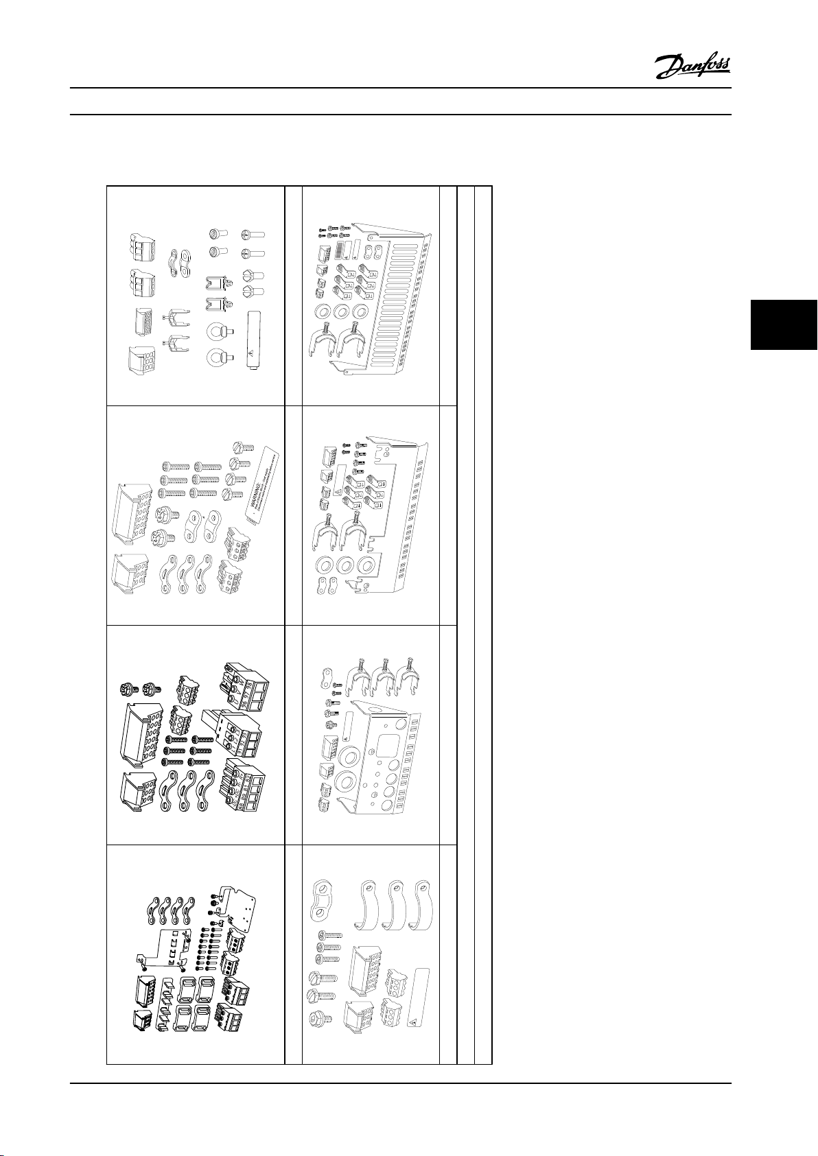
U
96
97
98
L1
L2
L3
91
92
93
V
W
RELAY 1
RELAY 1
03
02
01
06
05
04
10
10
06
06
130BT309.10
130BT339.10
130BT330.10
130BA406.10
61 68 6
39 42 50 53 54 5
03 02 01
06 05 04
A
B
C D
E
F
G
H
I
J K
WARNING:
Risk of Electric Shock - Dual supply
Disconnect mains and loadsharing before service
ISOA0021
61
68
39
42
50
53
54
RELAY 1
RELAY 2
03
02
01
06
05
04
130BT346.10
WARNING:
Risk of Electric Shock - Dual supply
Discunnect mains and loadsharing before service
61
68
39
50
53
54
5
42
03
02
01
06
05
04
99
95
130BT347.10
WARNING:
Risk of Electric Shock - Dual supply
Disconnect mains and loadsharing before service
99
95
61
68
39
50
53
54
5
42
03
02
01
06
05
04
130BT348.10
Risk of Electric Shock - Dual supply
Disconnect mains and loadsharing before service
WARNING:
RELAY 1
RELAY 2
61
68
39
50
53
54
5
42
03
02
01
06
05
04
130BT349.10
RELAY 1
RELAY 2
WARNING
STORED CHARGE DO NOT TOUCH UNTIL
15 MIN. AFTER DISCONNECTION
CHARGE RESIDUELLE.
ATTENDRE 15 MIN. APRES DECONNEXION
WARNING
:
Risk of Electric Shock - Dual supply
Disconnect mains and loadsharing before service
Mechanical Installation Design Guide
5.1.3 Accessory Bags
5 5
MG11BC22 Danfoss A/S © Rev. 06/2014 All rights reserved. 89
Enclosure type A1, A2 and A3 Enclosure type A56 Enclosure type B1 and B2 Enclosure type C1 and C2
Enclosure type B3 Enclosure type B4 Enclosure type C3 Enclosure type C4
1 + 2 only available in units with brake chopper. For the DC link connection (load sharing), connector 1 can be ordered separately (code no. 130B1064).
Table 5.3 Parts included in Accessory Bags
An 8-pole connector is included in accessory bag for FC 102 without Safe Torque Off.
Page 92
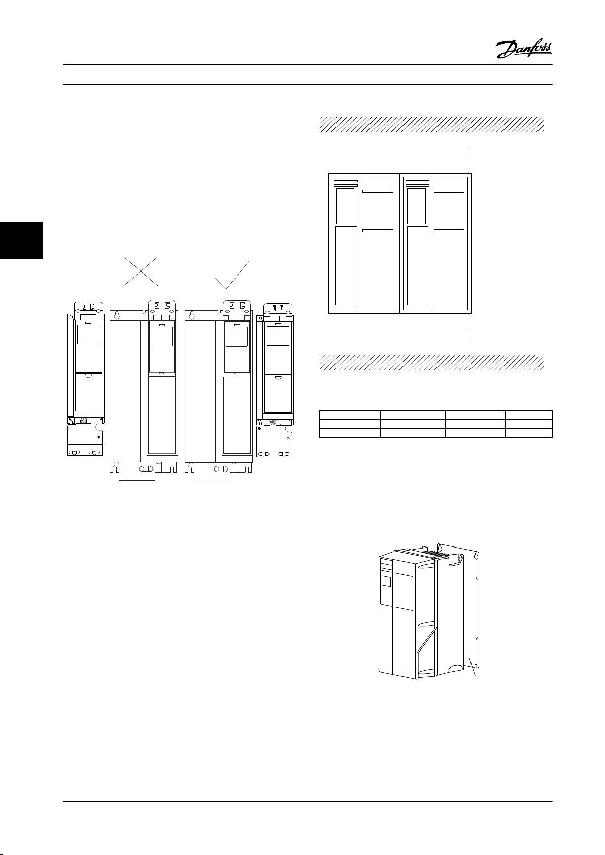
130BD389.11
A2
B3 B3
A2
a
b
130BA419.10
130BA219.11
1
Mechanical Installation Design Guide
5.1.4 Mechanical Mounting
All enclosure types allow side-by-side installation except
when a IP21/IP4X/TYPE 1 Enclosure Kit is used (see
chapter 3.1 Options and Accessories).
Side-by-side mounting
IP20 A and B enclosures can be arranged side-by-side with
no clearance required between them, but the mounting
order is important. Figure 5.1 shows how to mount the
55
frames correctly.
Figure 5.1 Correct Side-by-side Mounting
If the IP 21 Enclosure kit is used on enclosure type A2 or
A3, there must be a clearance between the adjustable
frequency drives of min. 2 in [50 mm].
For optimal cooling conditions, allow a free-air passage
above and below the adjustable frequency drive. See
Table 5.4.
Figure 5.2 Clearance
Enclosure type
a (ins [mm]) 3.94 [100] 7.87 [200] 8.86 [225]
b (ins [mm]) 3.94 [100] 7.87 [200] 8.86 [225]
Table 5.4 Air Passage for Different Enclosure Types
A2/A3/A4/A5/B1 B2/B3/B4/C1/C3 C2/C4
1. Drill holes in accordance with the measurements
given.
2. Provide screws suitable for the surface for
mounting the adjustable frequency drive.
Retighten all four screws.
Figure 5.3 Proper Mounting with Backplate
90 Danfoss A/S © Rev. 06/2014 All rights reserved. MG11BC22
Page 93
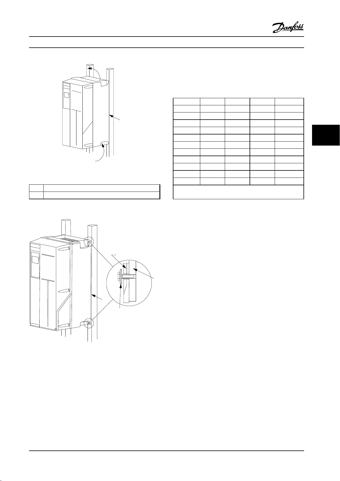
130BA228.11
1
130BA392.11
2
1
3
4
Mechanical Installation Design Guide
Figure 5.4 Proper Mounting with Railings
Item Description
1 Backplate
Mounting enclosure types A4, A5, B1, B2, C1 and C2 on a
non-solid back wall, the adjustable frequency drive must
be provided with a backplate, “1”, due to insufficient
cooling air over the heatsink.
Enclosure IP20 IP21 IP55 IP66
A2 * * - A3 * * - -
A4/A5 - - 1.48 [2] 1.48 [2]
B1 - * 1.62 [2.2] 1.62 [2.2]
B2 - * 1.62 [2.2] 1.62 [2.2]
B3 * - - -
B4 1.48 [2] - - C1 - * 1.62 [2.2] 1.62 [2.2]
C2 - * 1.62 [2.2] 1.62 [2.2]
C3 1.48 [2] - - C4 1.48 [2] - - -
* = No screws to tighten
- = Does not exist
5 5
Table 5.5 Legend to Figure 5.4
Figure 5.5 Mounting on a Non-solid Back Wall
Table 5.6 Tightening torque for covers (lb/ft [Nm])
Field Mounting
5.1.5
For field mounting the IP21/IP4X top/TYPE 1 kits or IP54/55
units are recommended.
MG11BC22 Danfoss A/S © Rev. 06/2014 All rights reserved. 91
Page 94
Electrical Installation Design Guide
6 Electrical Installation
6.1 Connections - Enclosure Types A, B
and C
6.1.1 Torque
NOTICE!
Cables General
All cabling must comply with national and local
regulations on cable cross-sections and ambient
66
temperature. Copper (167 °F [75 °C]) conductors are
recommended.
Aluminum Conductors
Terminals can accept aluminum conductors, but the
conductor surface must be clean, and the oxidation must
be removed and sealed by neutral acid-free Vaseline
grease before the conductor is connected.
Furthermore, the terminal screw must be retightened after
two days due to softness of the aluminum. It is crucial to
keep the connection a gas-tight joint; otherwise, the
aluminum surface will oxidize again.
92 Danfoss A/S © Rev. 06/2014 All rights reserved. MG11BC22
Page 95
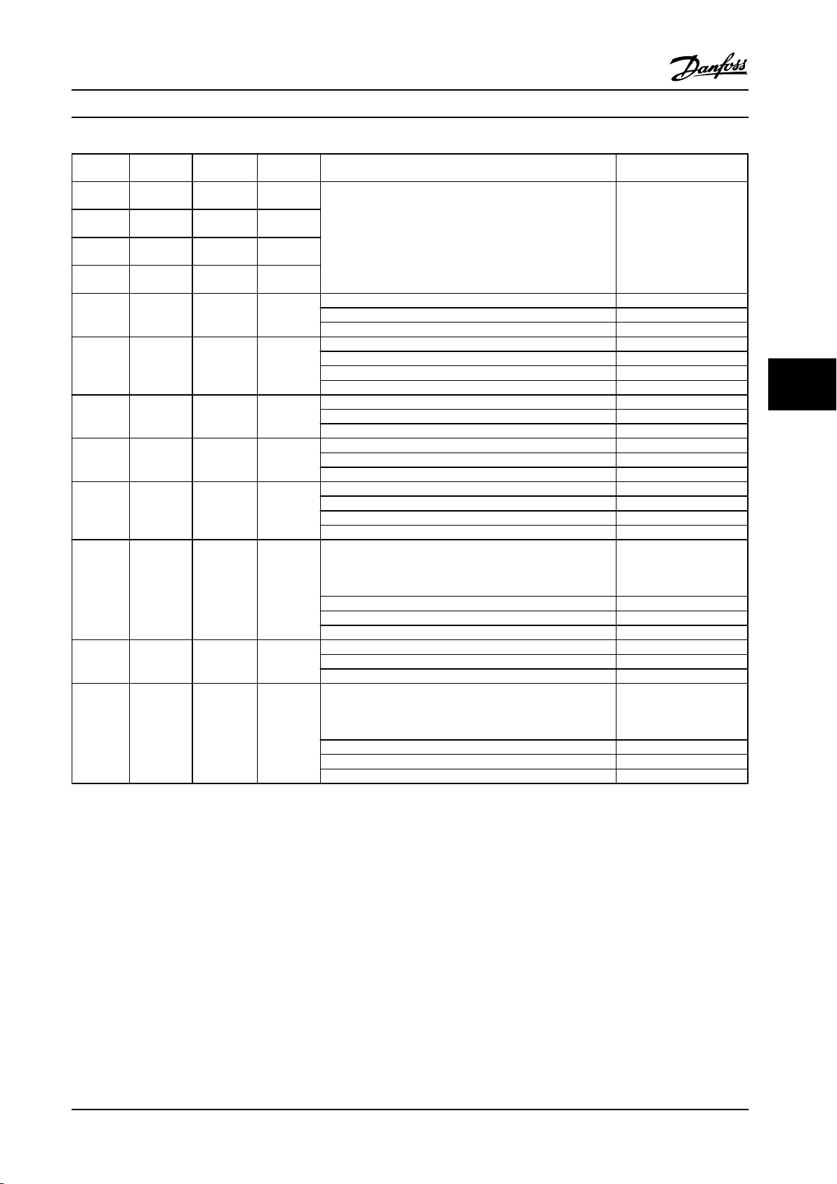
Electrical Installation Design Guide
Enclosure
type
A2 1.5–3
A3 4–5
A4 1.5–3
A5 1.5–5
B1 7.5–15
B2 20
B3 7.5–15
B4 11–25
C1 25–40
C2 50–60
C3 30–40
C4 50–60
200–240 V
(hp [kW])
[1.1–2.2]
[3–3.7]
[1.1–2.2]
[1.1–3.7]
[5.5–11]
[15]
[5.5–11]
[15–18]
[18–30]
[37–45]
[22–30]
[37–45]
380–480 V
(hp [kW])
1.5–5
[1.1–4]
7.5–10
[5.5–7.5]
1.5–5
[1.1–4]
1.5–10
[1.1–7.5]
15–25
[11–18]
30–40
[22–30]
15–25
[11–18]
30–50
[22–37]
50–75
[37–55]
100–125
[75–90]
60–75
[45–55]
100–125
[75–90]
525–690 V
(hp [kW])
-
-
-
- Line power, brake resistor, load sharing, motor cables 1.33 [1.8]
15–40
[11–30]
- Line power, brake resistor, load sharing, motor cables 1.33 [1.8]
- Line power, brake resistor, load sharing, motor cables 3.32 [4.5]
- Line power, brake resistor, load sharing cables 7.38 [10]
50–125
[37–90]
- Line power, brake resistor, load sharing, motor cables 7.38 [10]
- Line power, motor cables 10.33 [14] (up to
Cable for Tightening up torque
(lb/ft [Nm])
Relay 0.37–0.44 [0.5–0.6]
Ground 1.48–2.21 [2–3]
Line power, brake resistor, load sharing cables 3.32 [4.5]
Motor cables 3.32 [4.5]
Relay 0.37–0.44 [0.5–0.6]
Ground 1.48–2.21 [2–3]
Relay 0.37–0.44 [0.5–0.6]
Ground 1.48–2.21 [2–3]
Relay 0.37–0.44 [0.5–0.6]
Ground 1.48–2.21 [2–3]
Motor cables 7.38 [10]
Relay 0.37–0.44 [0.5–0.6]
Ground 1.48–2.21 [2–3]
Line power, motor cables 10.33 [14] (up to
4/0 AWG [95 mm2])
17.7 [24] (over 4/0 AWG
[95 mm2])
Load sharing, brake cables 10.33 [14]
Relay 0.37–0.44 [0.5–0.6]
Ground 1.48–2.21 [2–3]
Relay 0.37–0.44 [0.5–0.6]
Ground 1.48–2.21 [2–3]
4/0 AWG [95 mm2])
17.7 [24] (over 4/0 AWG
[95 mm2])
Load sharing, brake cables 10.33 [14]
Relay 0.37–0.44 [0.5–0.6]
Ground 1.48–2.21 [2–3]
6 6
Table 6.1 Tightening-up Torque
MG11BC22 Danfoss A/S © Rev. 06/2014 All rights reserved. 93
Page 96
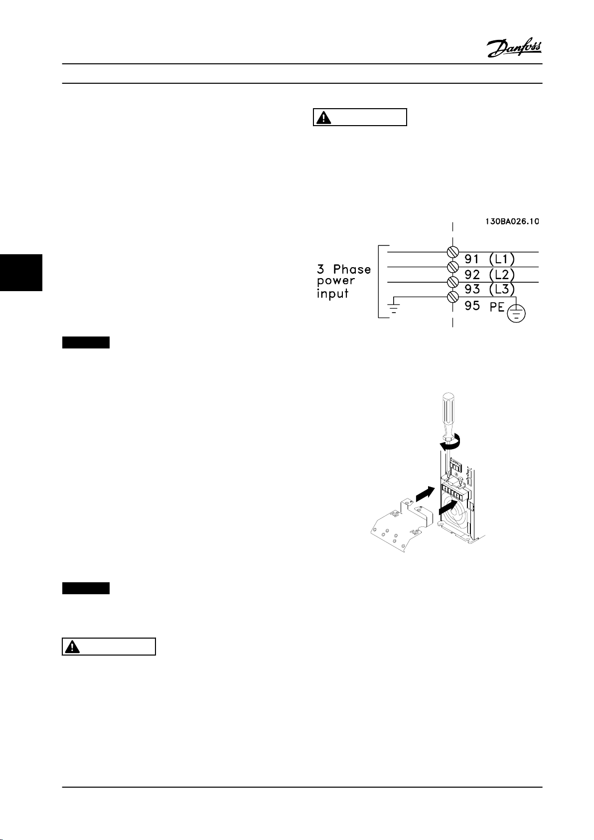
-DC+DC
BR- BR+ U V W
99
M A I N S
95
RELAY 1 RELAY 2
- LC +
130BA261.10
Electrical Installation Design Guide
6.1.2 Removal of Knockouts for Extra
Cables
1. Remove the cable entry from the adjustable
frequency drive (this prevents foreign parts from
CAUTION
The ground connection cable cross-section must be at
least 10 mm2 or 2 x rated line power wires terminated
separately according to EN 50178.
falling into the adjustable frequency drive when
removing knockouts).
2. Cable entry has to be supported around the
The AC line input connection is fitted to the line power
switch if this is included.
knockout to be removed.
3. The knockout can now be removed with a strong
mandrel and a hammer.
4. Remove burrs from the hole.
66
5. Mount the cable entry on the adjustable
frequency drive.
Connection to Line and Grounding
6.1.3
Figure 6.1 AC line input connections
NOTICE!
The plug connector for power can be plugged on
adjustable frequency drives of up to 10 hp [7.5 kW].
1. Fit the two screws in the de-coupling plate, slide
it into place and tighten the screws.
2. Make sure the adjustable frequency drive is
properly grounded. Connect to ground
connection (terminal 95). Use screw from the
accessory bag.
3. Place plug connector 91 (L1), 92 (L2), 93 (L3) from
the accessory bag onto the terminals labeled
MAINS at the bottom of the adjustable frequency
drive.
4. Attach the line wires to the line power plug
connector.
5. Support the cable with the enclosed supporting
brackets.
AC line input connection for enclosure types A1, A2
and A3:
Figure 6.2 Fitting the Mounting Plate
NOTICE!
Ensure that AC line voltage corresponds to the AC line
voltage on the nameplate.
CAUTION
IT Line Power
Do not connect 400 V adjustable frequency drives with
RFI filters to line power supplies with a voltage between
phase and ground of more than 440 V.
94 Danfoss A/S © Rev. 06/2014 All rights reserved. MG11BC22
Page 97
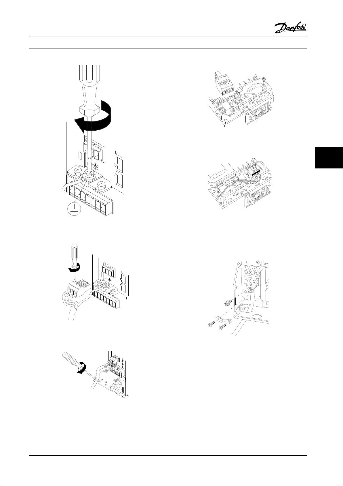
130BA262.10
M
I N S
+DC
BR-
BR+
U
V
W
RELAY 1 RELAY 2
95
130BA263.10
95
M
A
INS
+DC
BR-
BR+
U
V
W
91
92
93
L1
L2
L3
RELAY 1 RELAY 2
+DC
BR-
BR+
U
V
W
MAINS
L1 L2 L3
91 92 93
RELAY 1 RELAY 2
99
- LC -
130BA264.10
L 1
L 2
L 3
91
92
93
130BT336.10
130BT335.10
130BT332.10
Electrical Installation Design Guide
AC line input connector enclosure type A4/A5 (IP55/66)
Figure 6.6 Connecting to Line Power and Grounding without
Disconnector
6 6
Figure 6.3 Tightening the Ground Cable
Figure 6.4 Mounting Line Power Plug and Tightening
Wires
Figure 6.7 Connecting to Line Power and Grounding with
Disconnector
When disconnector is used (enclosure type A4/A5), the PE
must be mounted on the left side of the adjustable
frequency drive.
Figure 6.8 AC Line Input Connection Enclosure Types B1 and
B2 (IP21/NEMA Type 1 and IP55/66/ NEMA Type 12)
Figure 6.5 Tighten Support Bracket
MG11BC22 Danfoss A/S © Rev. 06/2014 All rights reserved. 95
Page 98
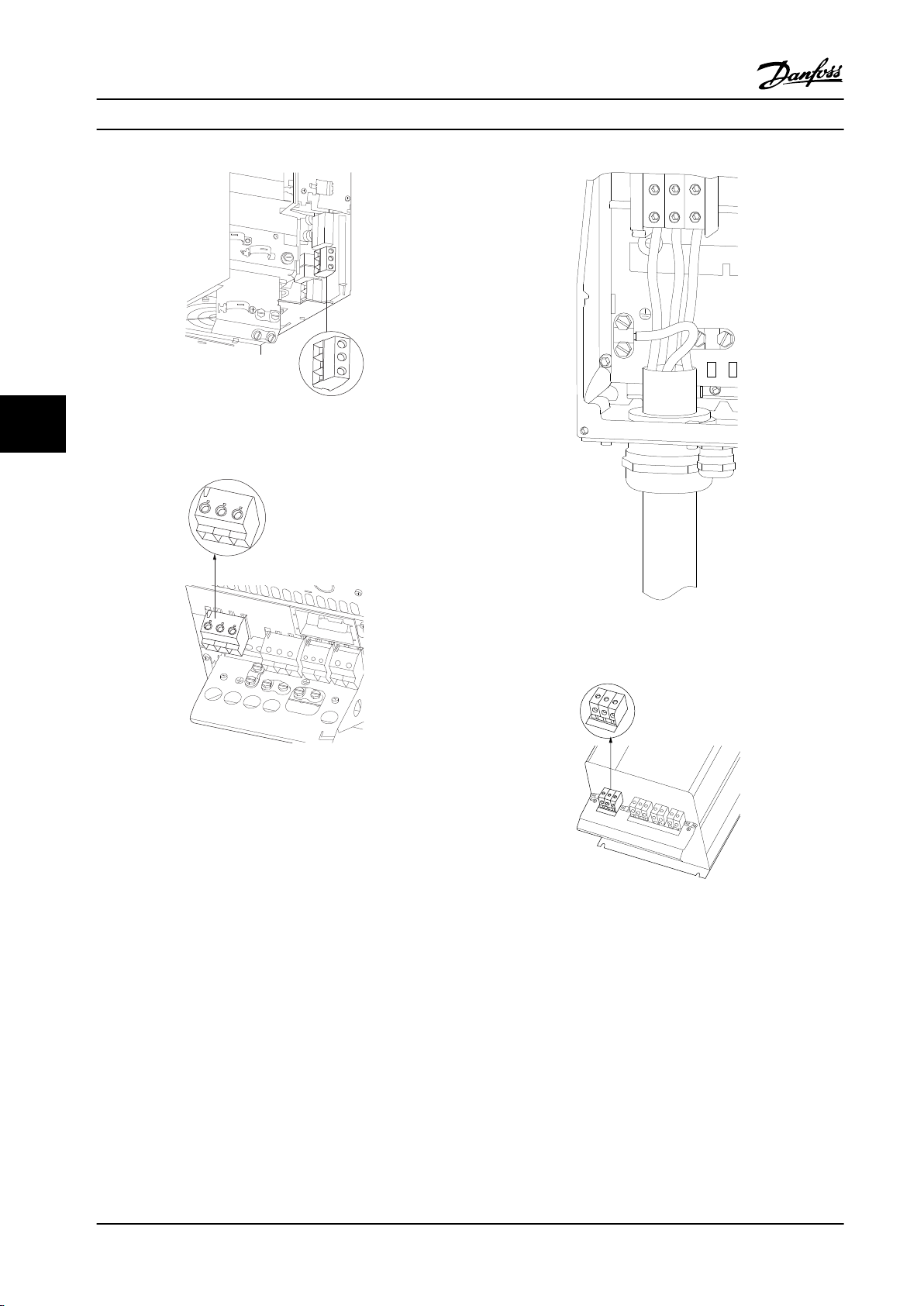
130BA725.10
L1 91
L2 92
L3 93
L1 91
L2 92
L3 93
U 96
V 97
W 98
DC-88
DC+89
R-81
R+82
130BA714.10
95
99
130BA389.10
95
91
L1
92
L2
93
L3
91 92 93
91 92 93
96 97 98
88 89
81 82
99
95
130BA718.10
Electrical Installation Design Guide
Figure 6.9 AC Line Input Connection Enclosure Type B3
66
(IP20)
Figure 6.10 AC Line Input Connection Enclosure Type B4
(IP20)
Figure 6.11 AC Line Input Connection Enclosure Types C1
and C2 (IP21/NEMA Type 1 and IP55/66/NEMA Type 12).
Figure 6.12 AC Line Input Connection Enclosure Type C3
(IP20).
96 Danfoss A/S © Rev. 06/2014 All rights reserved. MG11BC22
Page 99
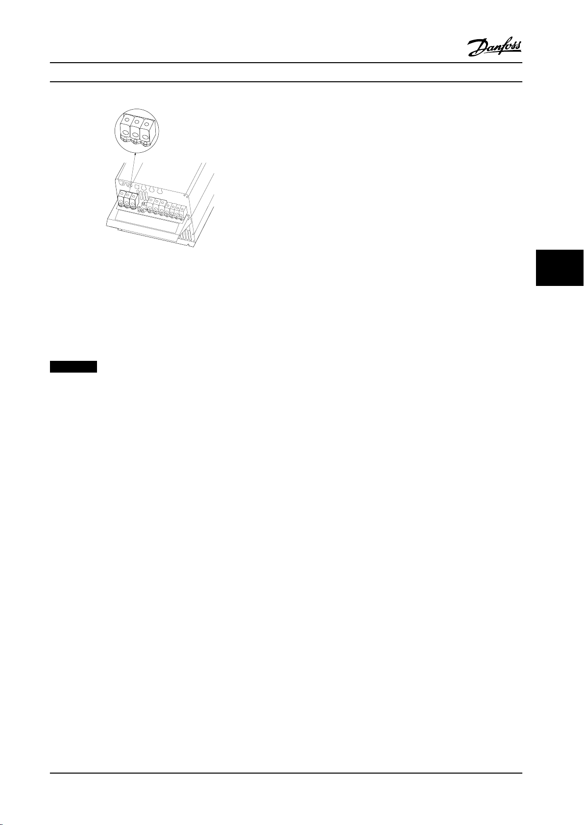
91
L1
L2
L3
92
93
91
L1
L2
L3
92
93
99
95
96
97
98
88
89
81
82
U
V
W
DC-
DC+
R-
R+
130BA719.10
Electrical Installation
Design Guide
Cable length and cross-section
The adjustable frequency drive has been tested with a
given length of cable and a given cross-section of that
cable. If the cross-section is increased, the cable
capacitance - and thus the leakage current - may increase,
thereby requiring that the cable length is reduced
accordingly. Keep the motor cable as short as possible to
reduce the noise level and leakage currents.
Switching frequency
When adjustable frequency drives are used with sine-wave
filters to reduce the acoustic noise from a motor, the
Figure 6.13 AC Line Input Connection Enclosure Type C4
(IP20).
switching frequency must be set according to the sinewave filter instruction in 14-01 Switching Frequency.
6 6
1. Fasten decoupling plate to the bottom of the
Usually the power cables for line power are non-shielded
cables.
adjustable frequency drive with screws and
washers from the accessory bag.
2. Attach motor cable to terminals 96 (U), 97 (V),
Motor Connection
6.1.4
NOTICE!
To comply with EMC emission specifications, shielded/
armored cables are required. For more information, see
chapter 2.9.2 EMC Test Results.
98 (W).
3. Connect to ground connection (terminal 99) on
decoupling plate with screws from the accessory
bag.
4. Insert plug connectors 96 (U), 97 (V), 98 (W)
(up to 10 hp [7.5 kW]) and motor cable to
terminals labeled MOTOR.
See chapter 9 General Specifications and Troubleshooting for
correct dimensioning of motor cable cross-section and
length.
5. Fasten shielded cable to the decoupling plate
with screws and washers from the accessory bag.
All types of three-phase asynchronous standard motors can
Shielding of cables:
Avoid installation with twisted shield ends (pigtails). They
spoil the shielding effect at higher frequencies. If it is
necessary to break the shield to install a motor isolator or
motor contactor, the shield must be continued at the
be connected to the adjustable frequency drive. Normally,
small motors are star-connected (230/400 V, Y). Large
motors are normally delta-connected (400/690 V, Δ). Refer
to the motor nameplate for correct connection mode and
voltage.
lowest possible HF impedance.
Connect the motor cable shield to both the decoupling
plate on the adjustable frequency drive and to the metal
housing on the motor.
Make the shield connections with the largest possible
surface area (cable clamp). This is done by using the
supplied installation devices in the adjustable frequency
drive.
If it is necessary to split the shield to install a motor
isolator or motor relay, continue the shield with the lowest
possible HF impedance.
Procedure
1. Strip a section of the outer cable insulation.
2. Position the stripped wire under the cable clamp
to establish mechanical fixation and electrical
contact between cable shield and ground.
3. Connect ground wire to the nearest grounding
terminal in accordance with grounding
instructions.
4. Connect the three-phase motor wiring to
terminals 96 (U), 97 (V), and 98 (W), see
Figure 6.14.
5. Tighten terminals in accordance with the
information provided in chapter 6.1.1 Torque.
MG11BC22 Danfoss A/S © Rev. 06/2014 All rights reserved. 97
Page 100
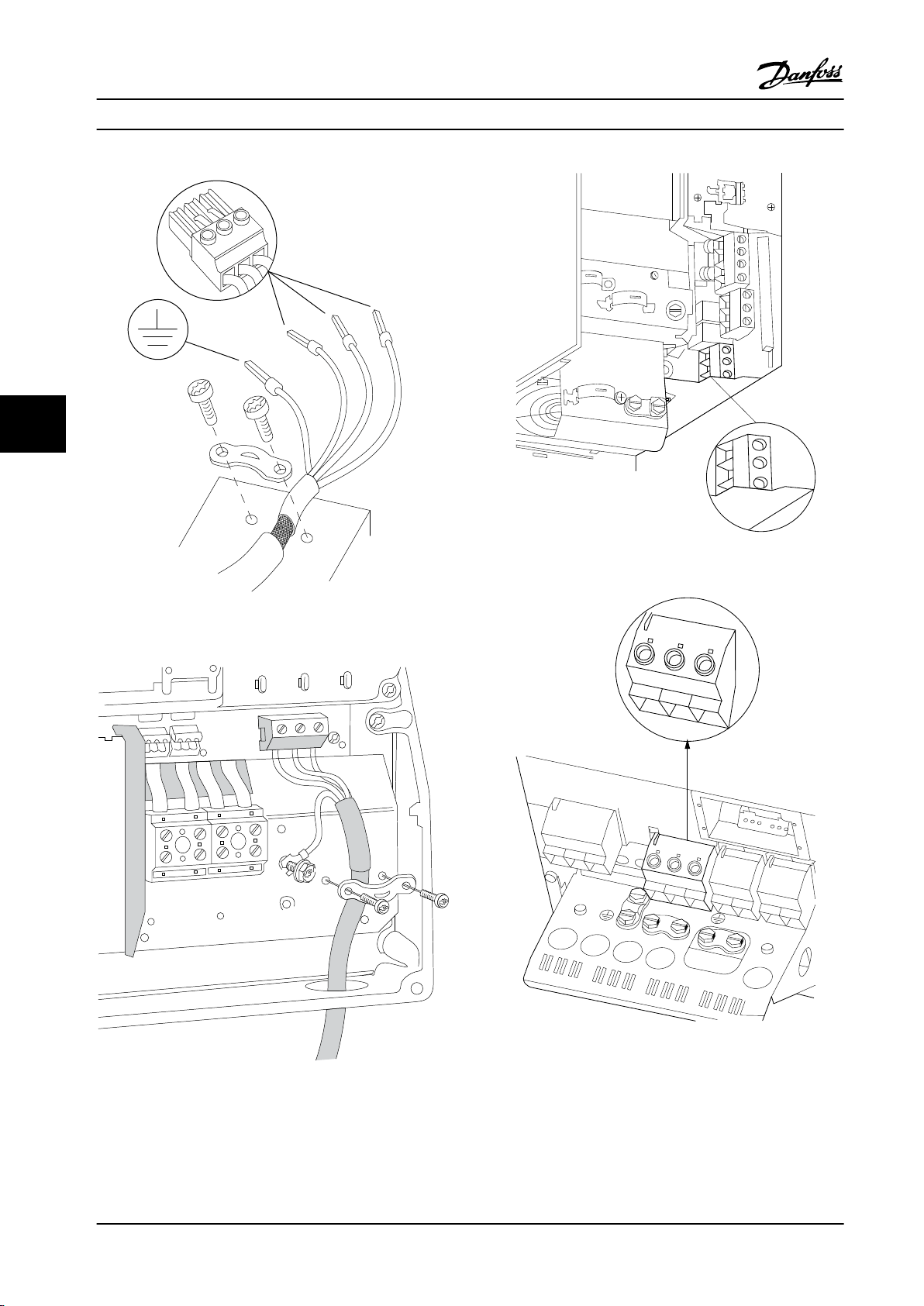
130BD531.10
U
V
W
96
97
98
130BT333.10
130BA726.10
U
96
V
97
W
98
U
96
V
97
W
98
L1
91
L2
92
L3
93
DC-
88
DC+
89
R-
81
R+
82
130BA721.10
99
Electrical Installation Design Guide
66
Figure 6.16 Motor Connection for Enclosure Type B3
Figure 6.14 Motor Connection
Figure 6.17 Motor Connection for Enclosure Type B4
Figure 6.15 Motor Connection for Enclosure Type B1 and B2
(IP21/NEMA Type 1, IP55/NEMA Type 12 and IP66/NEMA
Type 4X)
98 Danfoss A/S © Rev. 06/2014 All rights reserved. MG11BC22
 Loading...