

Page 1
Technical Information
Passive Force Feedback Electric Steering Wheel Bas
e
powersolutions.danfoss.com
Page 2

Technical Information
e-Wheel 100
Revision history Table of re
Date Changed Rev
January 2020 Second Edition : Corrected RPM operating speed
September 2019
visions
Fir
st Edition
0102
0101
© 2019 Danfoss A/S. All rights reserved
All trademarks in this material are properties of their respective owners.
PLUS+1, GUIDE and Sauer-Danfoss are trademarks of Danfoss A/S.
2 | © Danfoss | September 2019 BC318774147046en-000101
Page 3

Technical Information
e-Wheel 100
Table of Contents
iterature References ...................................................................................................................................................................... 4
L
OEM responsibility ........................................................................................................................................................................... 5
Introduction ..................................................................................................................................................................................... 6
e-Wheel 100 ...................................................................................................................................................................................................................................... 6
Features of e-Wheel ....................................................................................................................................................................................................................... 6
Benefits of e-Wheel ........................................................................................................................................................................................................................ 7
e-Wheel Safety Functions ............................................................................................................................................................................................................ 7
Application Example ...................................................................................................................................................................................................................... 7
Different steering wheel sizes .................................................................................................................................................................................................... 9
e-Wheel Torque Control Algorithms ............................................................................................................................................ 10
Information Flow Block Diagram .............................................................................................................................................................................................10
Graphical Representation of Torque featuring various control algorithms ............................................................................................................11
End-Stop Torque Control ...........................................................................................................................................................................................................12
Base Torque Control .....................................................................................................................................................................................................................12
RPM Torque Control .....................................................................................................................................................................................................................12
Warning Control Torque .............................................................................................................................................................................................................14
Vehicle Speed Torque Control .................................................................................................................................................................................................15
Technical Data ................................................................................................................................................................................ 16
Mechanical characteristics .........................................................................................................................................................................................................16
Electrical characteristics ..............................................................................................................................................................................................................16
CAN (Controller Area Network) ................................................................................................................................................................................................16
Connector type and Pin Configuration .................................................................................................................................................................................16
Environmental characteristics ..................................................................................................................................................................................................17
F
unctional Safety ...........................................................................................................................................................................................................................17
Communication Protocol .............................................................................................................................................................. 18
Messages from e-Wheel to steering controller [AUX_STW_P and AUX
Messages from Vehicle speed sensor to steering controller and to e-Wheel [VSP_P and VSP_R] ..................................................................20
Messages from steering controller to e-Wheel ..................................................................................................................................................................21
Installations .................................................................................................................................................................................... 25
Dimensions ......................................................................................................................................................................................................................................25
Instructions ......................................................................................................................................................................................................................................25
Variant and ordering specifications ............................................................................................................................................. 26
e-Wheel MMC .................................................................................................................................................................................................................................26
Code Numbers ...............................................................................................................................................................................................................................26
Variants codes for e-Wheel MMC ............................................................................................................................................................................................27
STW_R] ...................................................................................................19
_
3 | © Danfoss | September 2019 BC318774147046en-000101
Page 4

PVED-CLS
User Manual
L1525062
Technical Information
e-Wheel 100
Literature References
Purpose of the document
References
Definitions and Abbreviations
This document describes the technical specifications and features’ information of the e-Wheel,
applied with Danfoss electro-hydraulic steering valves and steering controller.
Literature Type Reference number
PVED-CLS Communication Protocol L1425546
PVED-CLS Safety Manual BC00000331
OSPE Steering valve, SASA
Sensor
EHi Steering Valve Technical Information BC00000379
Technical Information 11068682
e-Wheel
SbW
AgPL
SIL
CAN
PL
PVED-CLS
OSPE
EHi
Fail Safe
Fail Operational
PAE
Electric Steering Wheel Base
Steer-by-Wire
Agricultural Performance Level
Safety Integrity Level
Controller Area Network
Performance Level
Proportional Valve Digital – Closed Loop - Safety (steering valve controller)
Orbital Steering Product – Electro-hydraulic steering valve
Electro-hydraulic in-line steering valve
To detect fault, indicate fault to safe state system and revert to a safe
condition in the event of a breakdown or malfunction
To detect fault, indicate fault to safe state system and continue full
operation with enough redundancy level
Product Application Engineering
4 | © Danfoss | September 2019 BC318774147046en-000101
Page 5

Technical Information
e-Wheel 100
OEM responsibility
The OEM of a machine or vehicle in which Danfoss products are installed has the full responsibility for all consequences that
might occur. Danfoss has no responsibility for any consequences, direct or indirect, caused by failures or malfunctions.
•
The OEM shall perform a hazard and risk analysis for the target system to analyze if the relevant risks are
sufficiently reduced by the safety functions. The safety functions are provided by the involved functional safety
elements.
•
Danfoss has no responsibility for any accidents caused by incorrectly mounted or maintained equipment.
•
Danfoss does not assume any responsibility for Danfoss products being incorrectly applied or the system being
programmed in a manner that jeopardizes safety.
5 | © Danfoss | September 2019 BC318774147046en-000101
Page 6
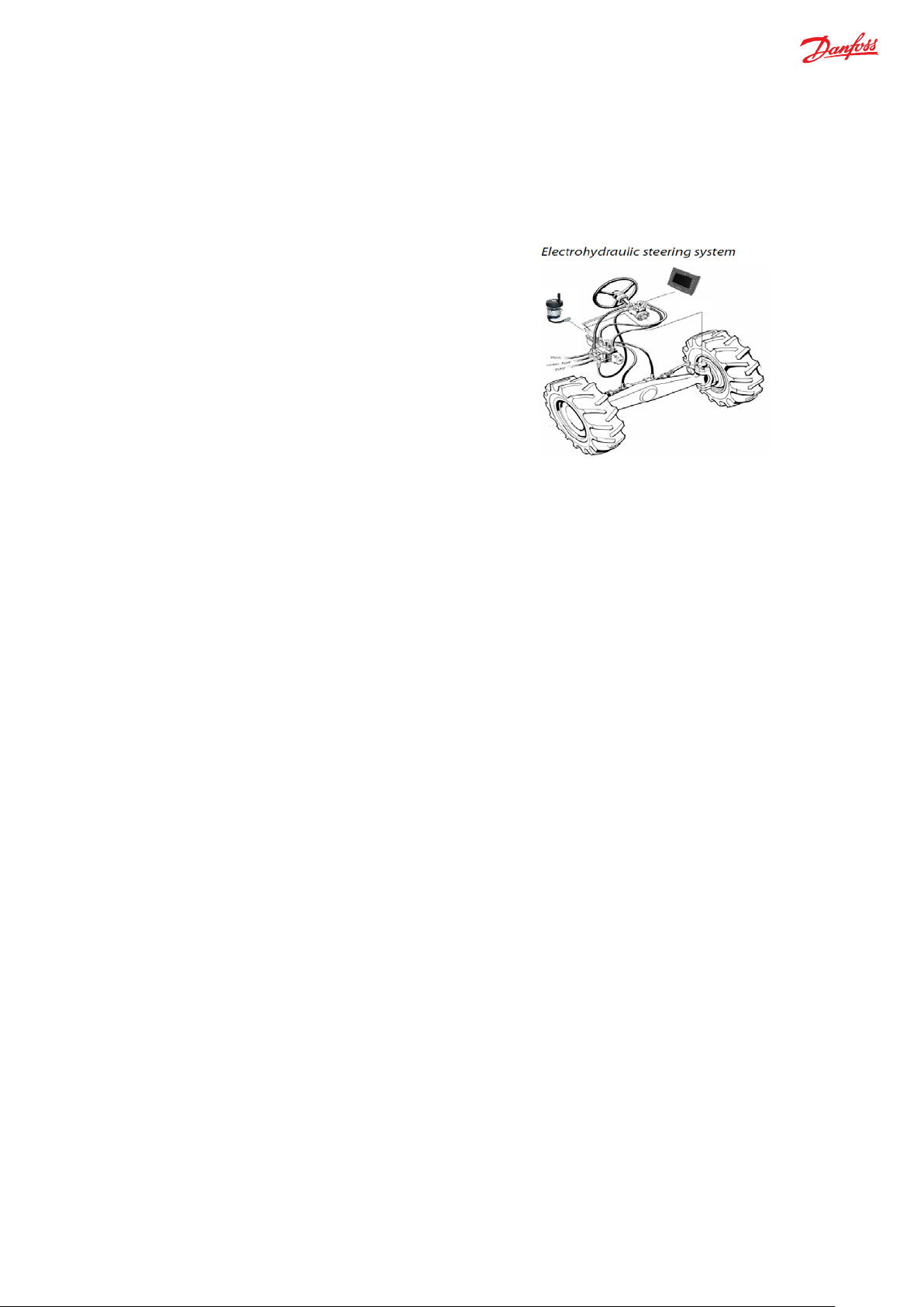
With the introduction of electro-hydraulic steering systems and
‘e-Wheel 100’ stands for Electric Steering Wheel Base, ‘100’ represents first of the series of Danfoss electric steering input devices.
Technical Information
e-Wheel 100
Introduction
eel 100
e-Wh
Danfoss steering products are used in vehicles where the driver must control high steering forces, reliably, comfortably and with
maximum safety.
Steer-by-Wire steering systems, applying electric steering wheel
advanced steering features like variable lock to lock ratio, softstop, anti-drift are possible, as easy integration in new vehicles
as well as retrofit to upgrade the existing vehicles. Primarily,
the objective of electric steering wheel is to offer high quality
steering feel, providing better operator comfort and reduce
operator fatigue. To meet this objective, Danfoss is now
offering electric steering input device ‘e-Wheel 100’.
‘e-Wheel 100’ is a haptic steering input device with passive force-feedback torque. ‘e-Wheel 100’ is referred to as ‘e-Wheel’
further in this document. The measured input steering angular position and the rate of change of steering angle from e-Wheel
are transmitted to steering valve controller, which determines the preferred steering response.
• e-Wheel is a ‘Plug and Play solution’ when interfaced directly to steering valve controller - PVED-CLS (for details refer
PVED-CLS User Manual), together with electro-hydraulic steering units OSPE / EHi.
• The communication protocol between e-Wheel and steering valve controller is based on the Danfoss proprietary safety
CAN protocol (refer PVED-CLS Communication Protocol).
• e-Wheel sub-system with PVED-CLS, supports realizing safe steering solutions designed to meet SIL 2/ PL d/ AgPL d by
designing the sub-system to a category 3 architecture (refer mini-steering wheel sub-system in PVED-CLS Safety
Manual).
In applications where e-Wheel is used as a primary steering input device or auxiliary steering input device, force-feedback is
necessary as the steering is expected not only to replicate same functions of conventional mechanically linked steering systems
(such as hydro-static enforced feedback) but also to provide advanced steering functions like:
• Directional control and wheel synchronization
• Variable steering ratio
• Smooth steering feel
The absence of hydro-static enforced feedback makes operator disconnected with the vehicle steering feedback which may
cause over or under steering. So, e-Wheel haptic passive force-feedback, mimics the feel of conventional steering systems, which
makes it a special attribute.
Features of e-Wheel
•
‘Plug and Play’ solution with PVED-CLS as steering controller
•
SIL Claim limit : 2
•
Dual channel redundant CAN bus interface
•
High quality steering feel
• Smooth steering torque control
• Absence of traditional steering wheel backlash and drift
• End-Stop feeling when vehicle wheels steered to extreme end-locks
• RPM torque for better controllability during Quick Steer
• Warning or event signal via steering wheel vibration
6 | © Danfoss | September 2019 BC318774147046en-000101
Page 7

Components
Description
e-Wheel 100
Primary steering input device
EHi (configuration type 7)
Electro-hydraulic steering unit
PVED-CLS
Steering valve Controller
WAS
Dual Analogue Wheel Angle sensor
VSP
CAN Vehicle Speed Sensor (Dual Channel)
MMI
Man-Machine Interface as well as a Gateway for primary vehicle speed message
(Dual Channel)
MC012
External Controller (as a redundant controller) for secondary vehicle speed
message
Vehicle ECU
OEM controller for braking function during any malfunction or events of failure
Technical Information
e-Wheel 100
Benefits of e-W
•
•
•
•
•
e-Wheel Safety Functions
1. Safe Steering Angular Position and Safe Steering Speed:
2. Safe Force-Feedback Brake Torque:
heel
Reduced operator fatigues due to improved ergonomics
Benefits for different steering solutions
• Electro-hydraulic steering solutions
• e-Wheel applied as auxiliary steering input device
• In case of failures, reliable fallback to the primary manual steering wheel
• Fail-Safe SbW solutions
• Eliminates steering column
• Cabin design freedom for OEMs
• Better accessibility for operator, flexibility in seat movements and orientation
Low power consumption
Compact and robust design
Easy to install
Two Channels of e-Wheel (each channel provides sub-system elements as the hall effect angle sensors, microprocessor
logic blocks, power supply conditioning and protection , CAN transceivers) independently measure angular positions,
calculate steering speeds and transmit both steering angular positions and steering speeds onto CAN bus (safety
protocol as per PVED-CLS communication protocol)
Applying force-feedback torque by e-Wheel as response to the data received via CAN bus (safety protocol as per PVEDCLS communication protocol). Software in the microprocessors will run various torque algorithms in response to the
system inputs, defining the required current for force feedback brake torque of e-Wheel. Both microprocessors within eWheel will also carry out independent monitoring of sub-systems elements to identify and react to subsystem faults.
Application Example
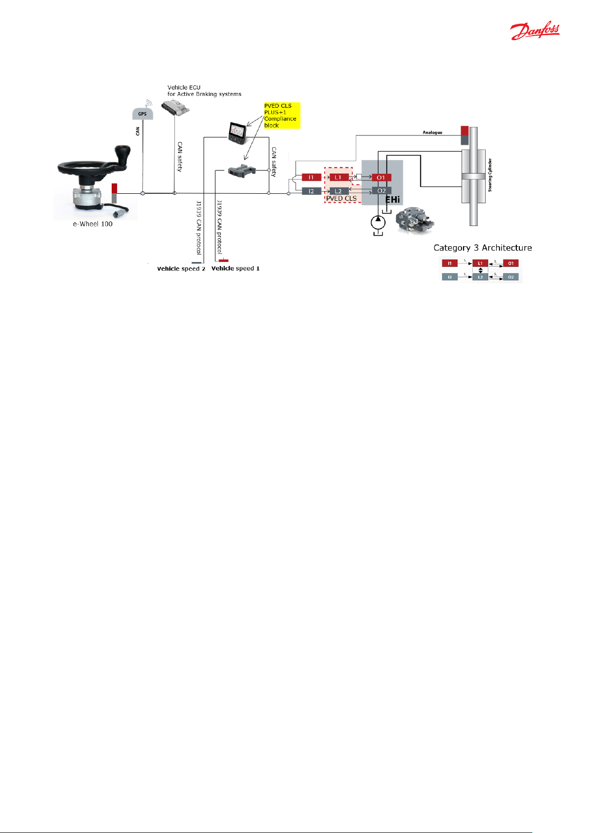
e-Wheel supports category 3 architecture and can be integrated in a Danfoss CAT 3 Fail-Safe Steering System with Danfoss EHi /
OSPE and PVED-CLS as steering valve controller (refer to EHi / OSPE Technical Information Document). In below example shown in
figure 1, we consider a Fail-Safe steering solution with Steer-by-Wire (SbW) system:
7 | © Danfoss | September 2019 BC318774147046en-000101
Page 8
Technical Information
e-Wheel 100
Figure 1 Fail-Safe Steer-by-Wire steering sub-system with e-Wheel
Here, e-Wheel is the primary steering input device in the vehicle with Fail-Safe steering system, which transmits the steering
angular positions and the rate of change of steering angle, via CAN bus, to the steering valve controller. The steering valve
controller uses the dual redundant analogue wheel angle sensor inputs, dual redundant vehicle speed messages and dual MMI
(display) message, as per PVED-CLS communication protocol. In this example, vehicle speed (VSP) message is as per standard CAN
J1939 protocol. So, the VSP messages further needs to be converted from standard CAN protocol to PVED-CLS communication
protocol using PLUS+1 functional block in the two redundant external controllers (Danfoss Display and Danfoss MC- 012
Controller). With above messages along-with the e-Wheel inputs, steering valve controller determines the appropriate steering
response.
For vehicles with Fail-Safe SbW steering systems only using EHi steering valve, manual activated emergency steering will not be
possible. Such steering systems must be set up with complete redundancy and limited only for off road usage. In case of failures,
vehicles must be brought to a defined safe state, for instance by stopping the vehicle or switching to a backup steering system. As
shown in figure 1, during the malfunction or events of failure, based on the operational status message from the steering
controller and the vehicle speed CAN safety message from the two plus+1 controllers, the vehicle ECU can signal the vehicle brake
systems for reduction of the speed and stopping the vehicle as a safe state response. Vehicle builder necessarily must perform
hazard and risk analysis, to have a “safe vehicle brake” safety function which the steering sub-system can demand. In order to
integrate with above steering system, suggested category is category 3. The steering controller will not monitor any status
message from the braking system and no action is intended to steering system related to the status of the braking system.
8 | © Danfoss | September 2019 BC318774147046en-000101
Page 9
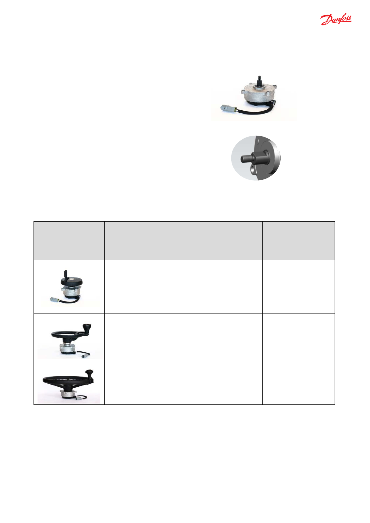
Danfoss offers e-Wheel – I without mounting any top steering
Figure 2
The steering wheels to be mounted on top, must be machined
Examples*
(* Danfoss does not offer the
possibilities with the
Steering wheel sizes to fit on
Recommended Torque for
Recommended Part
Mini-steering wheel
2 Nm
11224128 / 11198022
Medium size steering wheel
5 Nm
11224129 / 11243182
Larger size steering wheel
5 Nm
11224129 / 11243182
Technical Information
e-Wheel 100
Different steering wheel sizes
wheel, shown as per figure 2.
The shaft of e-Wheel is a ‘flat D-shaped’ shaft with:
• with a maximum axial force of 1500 N
• bending moment of 50 Nm
in a way that they accept the ‘flat D-shaped’ shaft of e-Wheel,
as shown in figure 3.
Figure 3
Below are few possibilities of different steering wheel sizes that can fit on shaft of the e-Wheel:
e-Wheel
steering wheels, below are
just the
e-Wheel)
corresponding steering
wheel size
Numbers
Recommendation:
• Danfoss offers e-Wheel with 5 Nm and 2 Nm as standard variants for maximum operating torque; choice of these
variants majorly depends on the type of application and the type of steering wheel size required in respective
application.
9 | © Danfoss | September 2019 BC318774147046en-000101
Page 10

Primary
Primary Primary
Primary
Prima ry
Steering Valve Controller
E-Wheel 100
Steering
Input Device
MMI Display
Analogue WAS
Vehicle Speed Sensor
MMI_P and MMI_R
AUX_STW_P and AUX_STW_R
STR_FB_MSG_X
VSP _P and V SP_R
Primary
Controller
Redundant
Controller
Primary
Controller
Redundant
Controller
Primary Redundant
Primary
Redundant
Primary
Redundant
Analog Input 1
Analog Input 2
STAT_MSG_OP_X
Cross check
Technical Information
e-Wheel 100
e-Wheel Torque Control Algorithms
The passive force- feedback torque is controlled by applying a proportional current, where the current is function of the below
mentioned control algorithms in e-Wheel. Force feedback torque will be based on, only one commanded control algorithm
offering maximum torque out of all available control algorithms in the configured variant of e-Wheel, at any instant applicable
during steering. Below is the list of e-Wheel Torque Control Algorithms:
• End Stop Torque
• Base Torque
• RPM Torque
• Vehicle Speed Dependent Torque
• Warning Control Torque
Information Flow Block Diagram
Figure 4 Block diagram for e-Wheel with steering valve controller
The operation between e-Wheel and steering controller in the steering system with relevant messages from each component is
simplified in figure 4. In terms of the primary purpose of e-Wheel, is giving steering inputs (steering angle and steering speed);
whereas the steering controller is defining the steering response based on the data available from all components in steering subsystem. The messages from each component in figure 4, are as per the PVED-CLS communication protocol, specified with the
respective annotations.
Recommendation:
• e-Wheel being a ‘Plug and Play solution’ with PVED -CLS, it is recommended to use PVED-CLS as steering valve controller.
• The Steering Primary and Redundant Controller must perform the cross checks to use e-Wheel in a safe way, refer PVED-
CLS Safety Manual.
• In Off Road Reaction/Non reaction mode, the controller detects AUX open loop device (e-Wheel 100) when, the steering
wheel velocity and the steering wheel angular position is above the threshold set in steering controller, along-with the
pre-condition that AUX device is set present and is allowed to steer (see flags in MMI message as per PVED CLS
communication protocol).
10 | © Danfoss | September 2019 BC318774147046en-000101
Page 11

Technical Information
e-Wheel 100
Graphical Representation of Torque featuring various control algorithms
The control algorithms in e-Wheel, are offered as standard variants with the torque values shown as per figure 5 and figure 6.
%End stop Torque %Base Torque %RPM Torque
100
90
80
70
60
50
40
% OF MAX. TORQUE
-100 -90 -80 -70 -60 -50 -40 -30 -20 -10 0 10 20 30 40 50 60 70 80 90 100
30
20
10
0
% WHEEL ANGLE
Figure 5 Torque Control Algorithms for 5 Nm
%End stop Torque %Base Torque %RPM Torque
100
90
80
70
60
50
40
% OF MAX.TORQUE
-100 -90 -80 -70 -60 -50 -40 -30 -20 -10 0 10 20 30 40 50 60 70 80 90 100
Figure 6 Torque Control Algorithms for 2 Nm
30
20
10
0
% WHEEL ANGLE
In above figures 5 and 6 respectively,
• ±100 % wheel angle shall correspond to maximum wheel angles on right and left end stop.
• Figure 5 represents for e-Wheel with 5 Nm as 100 % of the maximum operating torque and figure 6 represents for e-
Wheel with 2 Nm as 100 % of the maximum operating torque.
• RPM torque in both the above graph depicts that it can be experienced irrespective of the wheel angle position,
11 | © Danfoss | September 2019 BC318774147046en-000101
Page 12
Technical Information
e-Wheel 100
depending upon the allowable RPM, at corresponding steering lock to lock ratio from steering controller. Figure 5 shows,
the maximum RPM torque for 5Nm is defined for 90 % of the maximum operating torque; whereas figure 6 shows RPM
torque for 2Nm is defined for 60 % of the maximum operating torque.
End-Stop Torque Control
Wheel angle sensors close the feedback loop with the steering controller, ensuring the vehicle wheels’ match steering commands.
During the operation, steering controller transmits the estimated wheel angle values as a feedback message over CAN bus to the
e-Wheel, refer Figure 4. Based on this message, e-Wheel detects the wheel angle values and determines the torque force feedback.
As shown in figure 5 and figure 6, the End-Stop control algorithm increases linearly from 90 % to 100 % wheel angles and provides
maximum operating torque (torque of 5Nm or 2Nm based on the chosen e-Wheel variant) at 100 % wheel angle. Thus, operator
experiences the End- Stop torque feedback, on vehicle wheels reaching the maximum wheel angle limits. As soon as the operator
steers away from the end stop towards neutral, the torque drops to the base torque control, as explained below.
Base Torque Control
The background torque for normal steering, excluding end-stop conditions, is the base torque control. This torque is smooth and
persistent through-out steering at different wheel angles, as shown in figure 5 and figure 6, as 10 % of the maximum operating
torque.
RPM Torque Control
e-Wheel offers more-precise control at low speeds. In material handling applications, for instance, vehicles might require two or
three steering wheel turns lock to lock, for maneuvering at low speeds. Whereas in other applications, steering wheel turns lock to
lock needs to adjust the range to six or more turns for less sensitivity at high speeds. Regardless of how quickly the operator might
turn the steering wheel, e-Wheel limits steering speed, to not exceed the maximum allowable steering speed for a given lock to
lock configuration. The lock to lock configuration is provided in the feedback message from steering valve controller to e-Wheel.
This attribute of restricting higher steering speed than allowable steering speed is therefore called as RPM torque control.
Figure 7 shows the amount of torque requested (as a percentage of maximum allowable torque), as the operator approaches the
maximum allowable RPM (scaled to 1200 internal resolution) for the respective lock to lock ratio. The torque brake in e-Wheel is
applied by the algorithm to limit the actual steering speed so that the maximum steering speed is not exceeded highly. Figure 7
shows the maximum RPM torque is limited to 90 % of maximum operating torque of 5 Nm. This is applicable in case of medium to
larger steering wheel size application.
% RPM torque
100
90
80
70
60
50
40
30
% Max Torque
20
10
0
0 200 400 600 800 1000 1200
% of Maximum Allowable RPM (scaled to 1200 IR)
Figure 7 RPM torque for e-Wheel with 5 Nm
12 | © Danfoss | September 2019 BC318774147046en-000101
Page 13

Lock to Lock
Maximum Allowable steering speed (RPM)
1
25
2
50
3
75
4
100
5
125
6
150
7
175
8
200
Technical Information
e-Wheel 100
% RPM torque
70
60
50
40
30
%Max Torque
20
10
0
0 200 400 600 800 1000 1200
% of Maximum Allowable RPM (scaled to 1200 IR)
Figure 8 RPM control for e-Wheel with 2 Nm
Figure 8 shows maximum RPM torque is limited to 60 % of maximum operating torque of 2 Nm. This is applicable in case of ministeering wheel applications.
For different lock to lock shown in below table, the Max Allowable steering speed (RPM) is default in standard variants as:
13 | © Danfoss | September 2019 BC318774147046en-000101
Page 14

0
0x00
On-Road
Active through-out operation state
16
0x10
Off-Road Reaction
Active through-out operation state
17
0x11
Off-Road Non-reaction
Active through-out operation state
32
0x20
STW Program 1
Active through-out operation state
33
0x21
STW Program 2
Active through-out operation state
34
0x22
STW Program 3
Active through-out operation state
35
0x23
STW Program 4
Active through-out operation state
36
0x24
STW Program 5
Active through-out operation state
48
0x30
AUX Program 1
Active only if error occurs
49
0x31
AUX Program 2
Active only if error occurs
50
0x32
AUX Program 3
Active only if error occurs
51
0x33
AUX Program 4
Active only if error occurs
52
0x34
AUX Program 5
Active only if error occurs
64
0x40
GPS Steering
Active only if error occurs
65
0x41
GPS 2 Steering
Active only if error occurs
208
0xD0
Off-Road Safety-Check
Active through-out operation state
224
0xE0
Service mode – Direct Output Control
Active through-out operation state
225
0xE1
Service mode – Wheel angle sensor calibration
Active through-out operation state
226
0xE2
Service mode – Spool calibration
Active through-out operation state
227
0xE3
Service mode – Joystick calibration
Active through-out operation state
240
0xF0
Initialization
Active through-out operation state
255
0xFF
Safe State
Active through-out operation state
Powering up with no controller messages
Active through-out operation state
Technical Information
e-Wheel 100
Warning Control Torque
In case of missing messages or errors in CAN messages, steering valve controller goes to safe state and thus the e-Wheel provides
relevant error codes to steering valve controller which triggers the steering controller to a safe state mode. This makes e-Wheel to
send out warning to the operator by vibrational sensation via steering wheel. The vibrational feedback of e-Wheel also called as
Warning Control Torque, signals awareness to operator about the loss of steering control. In such events of failure, vehicles must
be defined with the necessary safe state conditions.
Steering Controller Outputs e-Wheel 100 Response
Value (Dec) Value (Hex) Current Operation state Warning Control Torque
14 | © Danfoss | September 2019 BC318774147046en-000101
Page 15

Technical Information
e-Wheel 100
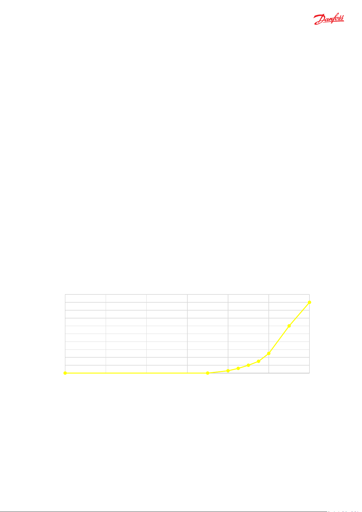
Vehicle Speed Torque Control
This torque eliminates vehicle resonances entering e-Wheel by providing gradually increasing torque dependency on vehicle
speed.
% Vehicle Speed Torque
10
9
8
7
6
5
4
% of Max Torque
3
2
1
0
0 10 20 30 40 50
Vehicle speed (Kph)
Figure 9 Vehicle Speed Torque
15 | © Danfoss | September 2019 BC318774147046en-000101
Page 16

Description
Value
Rated Torque
5.5 Nm Nominal (100 % command)
Off-State Torque
<0.5 Nm (0% command)
Operating Speed
Max Axial Force
1500 N
Max Bending Moment
50 Nm
Shaft Type
D shaped
Rotating Angle
360 °, without mechanical stop
Weight
1.5kg
Description
Value
Supply Voltage
12 VDC or 24 VDC (9-36 V), single common power
Coil Resistance
10 Ω nominal
Maximum Power Dissipated
15 Watts
Cable
20 AWG x 4 conductors
Description
Value
Standard
CAN 2.0B
Channels
Two
Baud Rate
250k Baud
Connector
DEUTSCH DT 04-4P*
PIN
Wire Color
Function
1 White
CAN-H
2 Blue
CAN-L
3 Red
V+ 4
Black
V-
Technical Information
e-Wheel 100
Technical Data
echanical characteristics
M
Electrical characteristics
300 RPM maximum
CAN (Controller Area Network)
Connector type and Pin Configuration
*Mating part to be bought externally
(Sealed cable with single connector withstands cable pull load
maximum 100 N)
16 | © Danfoss | September 2019 BC318774147046en-000101
Page 17

Description
Value
Operating Temperature
-40 °C to 85 °C
Storage Temperature
-40 °C to 95 °C
Ingress Protection (IP) rating
IP66
Environmental Testing Std.
ISO 16750-4 §5.1 per IEC 60068-2
Description
e-Wheel Sensor Safety Specification
e-Wheel Brake Safety
Performance Level (EN 13849-1: 2015)
PLd
PLd
Hardware Fault Tolerance (HFT)
1
1
System
Fail Safe
Fail Safe
Safety Element Classification (IEC 62061)
Type B
Type B
Probability of Dangerous Failures
1.597 x 10⁻⁸
5.289 x 10⁻⁹
Safe Failure Fraction (SFF)
98.72%
99.25%
SIL Claim Limit (IEC 62061:2005)
2
2
Architecture (ISO 13849)
Category 3
Category 3
DC
High
High
Proof Test Interval / Mission Time
20 years
20 Years
MTTFd per channel (ISO 13849 Table K.1)
150 years
180 years
CCF factor (IEC 62061)
5 %
5 %
Technical Information
e-Wheel 100
Environmental characteristics
Functional Safety
(PFHDssD) (IEC 62061 : 2005)
Specification
(1)
(2)
Notes:
(1) The sensor sub-system is redundant. If one channel fails, the other channel continues transmitting data. However, the
steering controller can no longer perform diagnostics and a system safe state shall be reached. The system integrator
must ensure sufficient diagnostics, please refer Block Diagram.
(2) Reaching a DC= High, depends on a correctly working diagnostic function in the steering controller. (Refer to the PVED-
CLS Safety Manual.)
17 | © Danfoss | September 2019 BC318774147046en-000101
Page 18

Messages from e-Wheel to Steering Controller
Sensor message
Default Message
Main Controller
Safety
Controller
Auxiliary Steering
0x0CFF144F
P3299 =0x4F
e-Wheel = Auxiliary
0x0CFF154F
P3299 = 0x4F
Messages from PVED-CLS Steering Controller to e-Wheel
Steering Feedback
0xCFF1813
P3297 = 0x13
P3297= 0x5A
Operation Status
0x18FF2013
P3297 = 0x13
P3297= 0x5A
Messages from Vehicle Speed Sensor to e-Wheel and to Steering Controller
Vehicle Speed -
0xCFF40FB
P3294 =0xFB
Vehicle Speed -
0xCFF41FB
P3294 = 0xFB
Sensor CAN Messages to Steering Controller
Wheel Angle Sensor-
0x0CFF12FA
P3298 = 0xFA
Wheel Angle Sensor-
0x0CFF13FA
P3298 = 0xFA
Man Machine
0x0CEF13FC
P3295 =0xFC
Man Machine Interface
0x0CEF5AFC
P3295 = 0xFC
Technical Information
e-Wheel 100
Communication Protocol
The below table shows how the steering controller shall be parameterized in order to correctly send main and redundant sensor
CAN messages. The auxiliary steering device ID’s will be used for fail-safe applications. (Refer PVED-CLS communication protocol
for further details)
Device (Mini STW) –
e-Wheel Primary
Steering Device
(Mini STW) – eWheel Redundant
Primary
Redundant
ID
Parameter
P3321 =0x14
P3318 =0x40
Parameter
P3321 = 0x15
P3318 = 0x41
Primary
Redundant
Interface – Primary
– Secondary
18 | © Danfoss | September 2019 BC318774147046en-000101
P3320 = 0x12
P3320 = 0x13
P3297 =0x13
P3297 = 0x5A
Page 19

Bytes
Encoding
Value/Range
Description
1..2
U16
4096..65535
Steering angle 1 relative to the 0-index point [AUX_STW_pos_P]:
Information not available
3..4
U16
Steering angle velocity
5 - All 1
Reserved
6
Bits 8..5
15
Error codes [AUX_STW_error_code_P]:
No Error
Bits 4..1
0..15
Sequence number [AUX_STW_Seq_P], incremented by 1 in each AUX
Rolls over from 15 to 0
7..8
U16
0..65535
CRC16 for data bytes 1..6 [AUX_STW_CRC_P]:
Polynomial: 0 x C86C
Technical Information
e-Wheel 100
Messages from e-Wheel to steering controller [AUX_STW_P and AUX_STW_R]
This message transmits angle, current, and fault information from the e-Wheel.
Priority: 3
Nominal Transmission: 50 ms
Sent by: e-Wheel
Send to: PVED-CLS Steering controller
0..4095
0..40960
40961..65535
0
1
2
3
4
5
6
7
8..13
14
Steering angle in [360 / 4096 degree] steps, where:
0 corresponds to 0 degrees,
4095 corresponds to 359.912 degrees
Note: the steering angle rolls over from 4095 to 0 for clockwise activation
and from 0 to 4095 for counter clockwise activation
[AUX_STW_velocity_P]:
Steering angle velocity (offset -20480) in [ 30 / 20480 RPM] steps, where
0 corresponds to -300 RPM (300 RPM counter clockwise)
20480 corresponds to 0 RPM
40960 corresponds to 300 RPM (300 RPM clockwise)
Information not available
Reserved
Sensor chip error
Steering angle failure
CAN input message failure
Power failure
CPU failure
Memory failure
Force feedback failure
Reserved
Temperature warning
Note:
• The above messages should be dual messages for both Primary and Redundant controllers.
19 | © Danfoss | September 2019 BC318774147046en-000101
primary message
Page 20

1
U8
All 1
Reserved
2
Bits 8..7
Direction Indication [ VSP_Dir_P]:
Bits 6..1
All 1
Reserved
3..4
U16
64256..65535
Vehicle speed [VSP_Speed_P]:
Information not available
5 - All 1
Reserved
6
Bits 8..5
All 1
Reserved
Bits 4..1
0..15
Sequence number [VSP_Seq_P], incremented by 1 in each VSP primary
Rolls over from 15 to 0
7..8
U16
0..65535
CRC16 for data bytes 1..6 [VSP_CRC_P]:
Polynomial: 0 x C86C
Technical Information
e-Wheel 100
Messages from Vehicle speed sensor to steering controller and to e-Wheel [VSP_P and VSP_R]
This message contains information from the steering controller to the e-wheel
Nominal Transmission: 100 ms
Priority: 3
Sent by: Vehicle Speed
Sensor Send to: e-Wheel
Bytes Encoding Value/Range Description
00
01
10
11
0..64255
Vehicle Speed
This parameter specifies the vehicle speed, measured in (1/256 kph).
Sequence number
This parameter is an internal counter that runs from 0 – 15 and then loops back. It could be used by the eWheel to check for validity of the incoming message.
Note:
• The above messages should be dual messages for both Primary and Redundant controllers.
Forward
Reverse
Error Condition
Information not available
Measured vehicle speed in [1/256 kmph]
message
20 | © Danfoss | September 2019 BC318774147046en-000101
Page 21

Technical Information
e-Wheel 100
Messages from steering controller to e-Wheel
Feedback Message [STR_FB_MSG_X]
This message contains information from the steering controller to the e-Wheel, including control commands and
relevant system level information.
Priority: 3
Nominal Transmission: 50 ms
Sent by: Steering controller
Send to: e-Wheel
Note:
• The above messages are dual messages from both Primary and Redundant controller.
21 | © Danfoss | September 2019 BC318774147046en-000101
Page 22

Bytes
Encoding
Value/Range
Description
0x00
On-Road
0x11
Off-Road Non-reaction
0x23
STW Program 4
0x30
AUX Program 1
0x34
AUX Program 5
0x41
GPS 2 Steering
0xE1
00
Steering device changes allowed
11
Information not available
[Lockout_program_change_X]:
00
Program changes allowed
01
Program changes prohibited
Technical Information
e-Wheel 100
Operation message [STAT_MSG_OP_X]
This message contains information from the steering controller to the e-Wheel.
Priority: 6
Nominal Transmission: 100 ms
Sent by: Steering controller
Send to: e-Wheel
1
U8
0x10 Off-Road Reaction
0x20 STW Program 1
0x21 STW Program 2
0x22 STW Program 3
Current Operation state [OperationState_X]:
2
Bits 8..7
0x24 STW Program 5
0x31 AUX Program 2
0x32 AUX Program 3
0x33 AUX Program 4
0x40 GPS Steering
0xD0 Off-Road Safety-Check
0xE0 Service mode – Direct Output Control
Service mode – Wheel angle sensor calibration
0xE2 Service mode – Spool calibration
0xE3 Service mode – Joystick calibration
0xF0 Initialization
0xFF Safe State
Lock-out status for steering device changes
[Lockout_device_change_X]:
01 Steering device changes prohibited
10 Error condition
Bits 6..5
22 | © Danfoss | September 2019 BC318774147046en-000101
Lock-out status for STW/AUX program changes
10 Error condition
11 Information not available
Page 23

00
EH-Steering functionality allowed
11
Information not available
prohibited)
01
GPS Steering selected
10
GPS 2 Steering selected
11
Reserved
Bits 6..1
Service mode state [Service_mode_state_X]:
0x02..0x0F
Reserved
0x11
WAS calibration in progress
0x1D
WAS calibration counter update
0x1F
WAS calibration complete
0x21
Spool calibration inactive
0x23
Spool calibration armed
0x25
Spool parameters plausibility check
0x27
Spool parameters update
0x2D
Spool calibration counter update
0x2F
Spool calibration complete
0x31
Joystick calibration in progress
Technical Information
e-Wheel 100
Bits 4..3
Bits 2..1
3
Bits 8..7
4
U8
Lock-out status for EH-steering functionality [Lockout_EH_steering_X]:
01
10 Error condition
11 Information not available
00 AUX device steering allowed
01 AUX device steering prohibited
10 Error condition
00 No GPS receiver selected (GPS steering
All 1 Reserved
0x00 Direct output control reset
0x01
EH-Steering functionality prohibited by an external switch
AUX Steering device lockout status [Lockout_AUX_X]:
GPS receiver selection and lockout status [Lockout_GPS_X]:
Direct output control active
0x10 WAS calibration Reset
0x12..0x1C Reserved
0x1E WAS calibration failure
0x20 Spool calibration reset
0x22 Spool calibration getting armed
0x24 Spool calibration in progress
0x26 Spool parameters ready to update
0x28..0x2C Reserved
0x2E Spool calibration failure
0x30 Joystick calibration Reset
23 | © Danfoss | September 2019 BC318774147046en-000101
Page 24

0x32..0x3C
Reserved
0x3D
Joystick calibration counter update
0x3E
Joystick calibration failure
0x3F
Joystick calibration complete
0x40..0xFC
Reserved
0xFD
No analog joystick configured
0xFE
No wheel angle sensor configured
mode)
Bits 8..5
All 1
Reserved
0xC86C
Technical Information
e-Wheel 100
0xFF
5
6
7..8 U16 0..65535
Note
• The above messages are dual messages from both Primary and Redundant controllers
• In Off Road Reaction/Non reaction mode, the controller detects AUX open loop device (e-Wheel 100) when, the steering
-
Bits 4..1 0..15 Sequence number [OperationState_Seq_X]: Incremented by 1 in
wheel velocity and the steering wheel angular position is above the threshold set in steering controller, along-with the
pre-condition that AUX device is set present and is allowed to steer (see flags in MMI message as per PVED CLS
communication protocol).
All 1 Reserved
Information not available (Operation state other than service
each Operation status message.
Rolls over from 15 to 0
CRC16 for data bytes 1..6
[OperationState_CRC_X]: Polynomial:
24 | © Danfoss | September 2019 BC318774147046en-000101
Page 25
Technical Information
e-Wheel 100
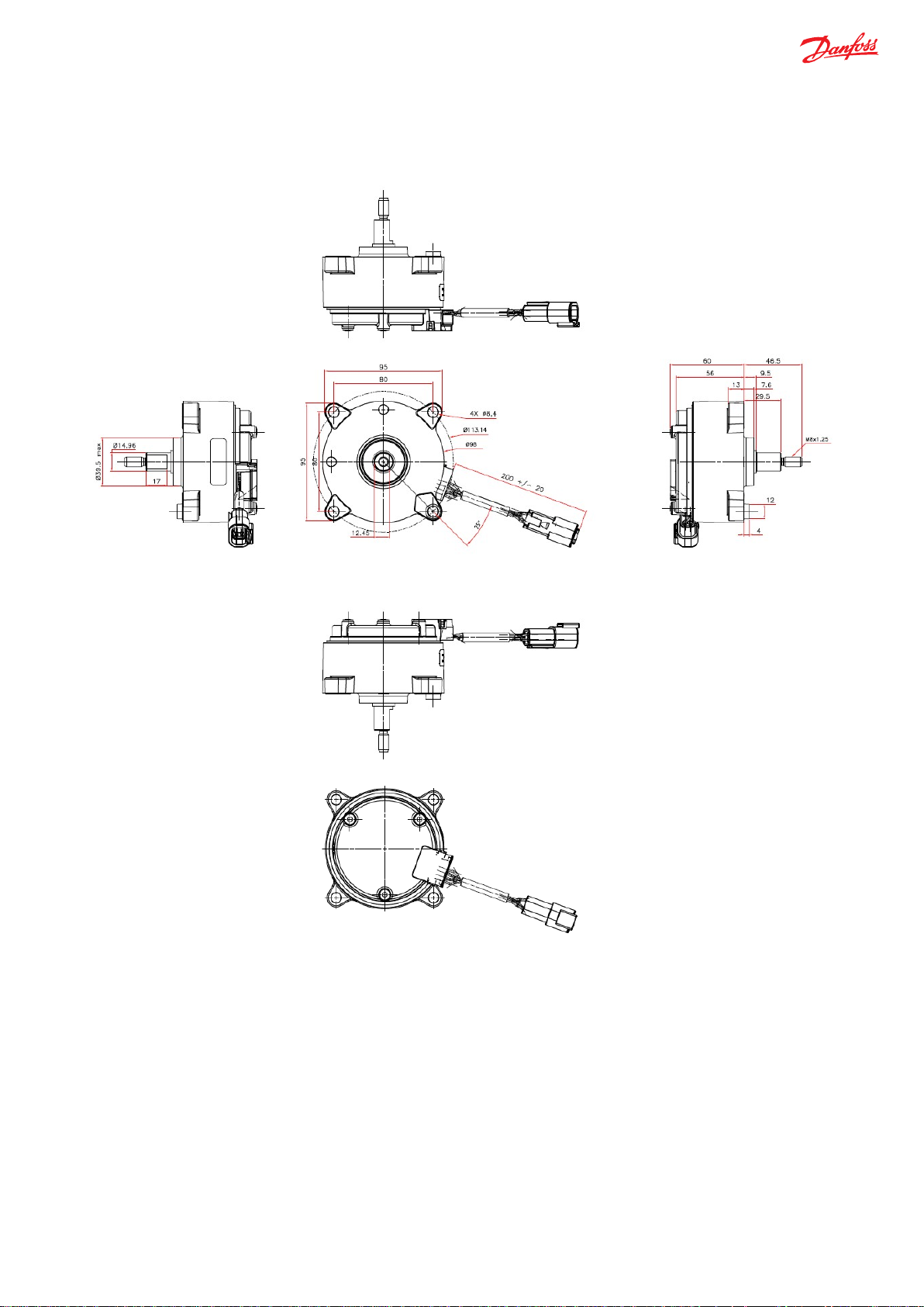
Installations
Dimensions
Instructions
-
To be installed such that shaft is between vertical axis and -10° from horizontal axis
-
Avoid misalignment that causes excessive load
25 | © Danfoss | September 2019 BC318774147046en-000101
Page 26

e-Wheel 100
1
CAN2
53
ES4
BS5
RPM6
Reserved7
VSP8
D9
Package10
Code
Configuratio
MMC Specifications according to above description format
11224128
Type 1
CAN 2
ES
BS N - VSP D S
11224129
Type 2
CAN 5
ES
BS
RPM -
VSP D S
11198022
Type 3
CAN 2
ES
BS N - VSP D M
11243182
Type 4
CAN 5
ES
BS
RPM -
VSP D M
Technical Information
e-Wheel 100
Variant and ordering specifications
e-Wheel MMC
Determine Master Model Code (MMC). Fill in with codes from Variant codes for e-Wheel, to specify e-Wheel 100. MMC
values for e-Wheel
Example only
e-Wheel 100
1
e-Wheel 100 base
2
Communication channel
3
Maximum Operating Torque (Nm)
4
End Stop Torque (Nm)
5
Base Torque (Nm)
6
RPM Torque (Nm)
7
Reserved
8
Vehicle Speed Torque (Nm)
9
Connector Type
10
Package
Code Numbers
Configuration Numbers, in the following table, are referring to matrix description for e-Wheel standard configurations.
Code numbers for catalog versions with specifications:
No.
n No.
26 | © Danfoss | September 2019 BC318774147046en-000101
Page 27

e-Wheel
Electric Steering Wheel Base
Code
e-Wheel 100
Type
Digital
Code
CAN
Maximum Operating Torque
5 Nm
2 Nm
Code 5 2
EndStop Torque
Included
Not Included
Code
ES N
Base Torque
Included
Not Included
Code
BS N
Code
RPM N
VSP Torque
Included
Not Included
Code
VSP N
Technical Information
e-Wheel 100
Variants codes for e-Wheel MMC
1) e-Wheel 100 base
2) Communication Channel
3) Maximum Operating Torque (Nm)
4) End Stop Torque (Nm)
5) Base Torque (Nm)
6) RPM (Nm)
RPM Torque Included Not Included
7) Reserved
8) Vehicle Speed Torque (Nm)
27 | © Danfoss | September 2019 BC318774147046en-000101
Page 28

Type, Connector
Deutsch DT, one 4 pin
Code D
Package
Single
Multiple
Code S
M
Technical Information
e-Wheel 100
9) Connector Type
10) Package
28 | © Danfoss | September 2019 BC318774147046en-000101
Page 29

Technical Information
e-Wheel 100
Page 30

Danfoss
Power Solutions GmbH & Co. OHG
Krokamp 35
D-24539 Neumünster, Germany
Phone: +49 4321 871 0
Danfoss
Power Solutions ApS
Nordborgvej 81
DK-6430 Nordborg, Denmark
Phone: +45 7488 2222
Danfoss
Power Solutions (US) Company
2800 East 13th Street
Ames, IA 50010, USA
Phone: +1 515 239 6000
Danfoss
Power Solutions Trading
(Shanghai) Co., Ltd.
Building #22, No. 1000 Jin Hai Rd
Jin Qiao, Pudong New District
Shanghai, China 201206
Phone: +86 21 2080 6201
Products we offer:
Hydro-Gear
www.hydro-gear.com
Daikin-Sauer-Danfoss
www.daikin-sauer-danfoss.com
DCV directional control
•
valves
Electric converters
•
Electric machines
•
Electric motors
•
Gear motors
•
Gear pumps
•
Hydrostatic motors
•
Hydrostatic pumps
•
Orbital motors
•
PLUS+1® controllers
•
PLUS+1® displays
•
PLUS+1® joysticks and
•
pedals
PLUS+1® operator
•
interfaces
PLUS+1® sensors
•
PLUS+1® software
•
PLUS+1® software services,
•
support and training
Position controls and
•
sensors
PVG proportional valves
•
Steering components and
•
systems
Telematics
•
Danfoss Power Solutions is a global manufacturer and supplier of high-quality hydraulic and
electric components. We specialize in providing state-of-the-art technology and solutions
that excel in the harsh operating conditions of the mobile off-highway market as well as the
marine sector. Building on our extensive applications expertise, we work closely with you to
ensure exceptional performance for a broad range of applications. We help you and other
customers around the world speed up system development, reduce costs and bring vehicles
and vessels to market faster.
Danfoss Power Solutions – your strongest partner in mobile hydraulics and mobile
electrification.
Go to www.danfoss.com for further product information.
We offer you expert worldwide support for ensuring the best possible solutions for
outstanding performance. And with an extensive network of Global Service Partners, we also
provide you with comprehensive global service for all of our components.
Local address:
Danfoss can accept no responsibility for possible errors in catalogues, brochures and other printed material. Danfoss reserves the right to alter its products without notice. This also applies to products
already on order provided that such alterations can be made without subsequent changes being necessary in specifications already agreed.
All trademarks in this material are property of the respective companies. Danfoss and the Danfoss logotype are trademarks of Danfoss A/S. All rights reserved.
©
Danfoss |
September 2019
BC318774147046en-000101
 Loading...