

Data sheet
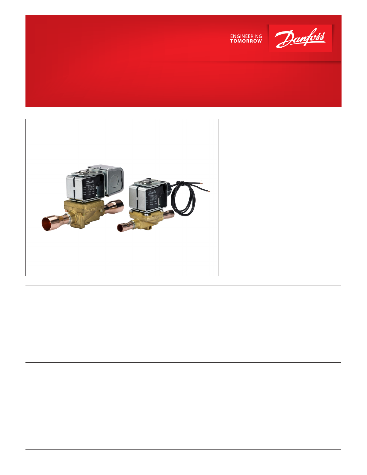
Solenoid valve
Type EVR 2 - EVR 40 Version 2
EVR is a direct or servo operated solenoid valve
suitable for liquid, suction, and hot gas lines with
most refrigerants, including flammable refrigerants.
EVR valves and coils are sold separately.
Features
Approvals • Pressure Equipment Directive (PED) 2014/68/EU
© Danfoss | DCS (az) | 2017.12
• Complete range of solenoid valves for
refrigeration, freezing and air conditioning plant
• Supplied in versions normally closed (NC) and
normally open (NO) with de-energized coil
• Wide choice of coils for AC and DC
• Suitable for most refrigerants, including
flammable refrigerants
• Designed for media temperatures up to 221 °F
• Low Voltage Directive (LVD) 2014/35/EU
• UL429 General Purpose Valve
• EAC
• UA
• Flare connections up to 5⁄8 in
• Solder connections up to 2 1⁄8 in
• Extended ends on solder versions make the
installation easy, eliminating the need to
dismantle the valve when soldering in
• Available in flare, solder and flange
connection versions
• ATEX zone 2
• CQC
• RoHS II
• For Marine approvals: Contact Danfoss for latest
updates
DKRCC.PD.BB0.F2.22 | 1

Data sheet | Solenoid valve, types EVR 2 - EVR 40 Version 2
Table of contents
Technical data ............................................................................................................................................................................. 3
Rated capacity [TR] ................................................................................................................................................................... 4
Ordering ....................................................................................................................................................................................... 5
EVR solder connection (NC) ........................................................................................................................................... 5
EVR solder connection (NO) ........................................................................................................................................... 6
EVR flare connection (NC) ............................................................................................................................................... 6
EVR flare connection (NO) .............................................................................................................................................. 6
EVR flange connection (NC) ........................................................................................................................................... 7
EVRC solder connection (NC) ........................................................................................................................................ 7
BJ and BX coils .................................................................................................................................................................... 8
BG coils .................................................................................................................................................................................. 9
Function ......................................................................................................................................................................................10
Design and material specifications ...................................................................................................................................11
EVR 2 - EVR 3 solder and flare connection ..............................................................................................................11
EVR 4 - EVR 6 - EVR 8 solder and flare connection ...............................................................................................12
EVR 10 solder and flare connection ..........................................................................................................................13
EVR 15 - EVR 18 solder, flare and flange connection ...........................................................................................14
EVR 20 - EVR 22 solder and flange connection .....................................................................................................15
EVR 25 solder connection .............................................................................................................................................16
EVR 32 - EVR 40 solder connection ............................................................................................................................17
EVRC solder connection ................................................................................................................................................18
Dimensions and weights ......................................................................................................................................................19
EVR 2 - EVR 3 solder connection .................................................................................................................................19
EVR 4 - EVR 6 - EVR 8 solder connection ..................................................................................................................20
EVR 10 solder conncetion .............................................................................................................................................21
EVR 15 - EVR 18 solder connection ............................................................................................................................22
EVR 20 - EVR 22 solder connection ............................................................................................................................23
EVR 25 solder connection .............................................................................................................................................24
EVR 32 - EVR 40 solder conncetion ............................................................................................................................25
EVRC 15 solder connection ..........................................................................................................................................26
EVRC 20 solder connection ..........................................................................................................................................27
EVR 2 - EVR 3 flare connection ....................................................................................................................................28
EVR 6 flare connection ..................................................................................................................................................29
EVR 10 flare connection.................................................................................................................................................30
EVR 15 flare connection.................................................................................................................................................31
EVR 15 flange connection .............................................................................................................................................32
EVR 20 flange connection .............................................................................................................................................33
Extended capacity, Liquid ....................................................................................................................................................34
Extended capacity, Suction .................................................................................................................................................37
Extended capacity, Hot gas .................................................................................................................................................49
© Danfoss | DCS (az) | 2017.12
DKRCC.PD.BB0.F2.22 | 2
psi
Data sheet | Solenoid valve, types EVR 2 - EVR 40 Version 2
Technical data
Refrigerants
R22/R407C, R134a, R404A/R507, R410A, R407A,
R32, R290, R600, R600a, R1234yf, R1234ze, R407F,
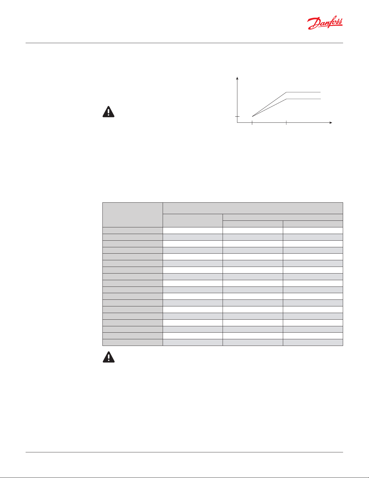
Max. working pressure
EVR solder and flare connections: 655 psi.
EVR flange connections: 460 psi.
R125, R152A, R448A, R449A, R452A, and R450A.
For a complete list of approved refrigerants, visit
www.products.danfoss.com and search for individual
code numbers, where refrigerants are listed as part
of technical data.
Special note for R152A, R32, R290, R600, R600a,
R1234yf, and R1234ze:
This product is validated in accordance to ATEX, ISO
5149, IEC 60335, and UL. Ignition risk is evaluated in
43.5
-40 32
Max. working pressure in bar in relation to media
temperature in °F.
accordance to ISO 5149 and IEC 60335.
See safety note at the bottom of this page.
Capacity
See extended capacity tables later in this data
Media temperature
sheet.
-40 – 221 °F
Max. 266 °F during defrosting
Ambient temperature and enclosure for coil
See separate data sheet for solenoid and ATEX coils.
Opening differential pressure
Type
Min.
EVR 2 NC 0 550 478
EVR 3 NC 0 550 261
EVR 4 NC 0.44 550 406
EVR 6 NC 0.44 550 406
EVR 6 NO 0.44 305 305
EVR 8 NC 0.44 550 406
EVR 10 NC 0.44 550 290
EVR 10 NO 0.44 305 305
EVR 15 NC 0.44 550 290
EVR 15 NO 0.44 305 305
EVR 18 NC 0.44 550 290
EVR 20 NC 0.44 550 290
EVR 20 NO 0.44 276 276
EVR 22 NC 0.44 550 290
EVR 22 NO 0.44 276 276
EVR 25 NC 2.9 450 246
EVR 32 NC 2.9 450 246
EVR 40 NC 2.9 450 246
with standard coil ∆p [psi]
Max. (= MOPD) liquid
AC coil [14-17 W] DC coil [20 W]
655 psi
460 psi
°F
The EVR 2 - EVR 22 with solder connections and
without manual stem can be applied on systems
with R152A, R32, R290, R600, R600a, R1234yf, and
R1234ze as the working fluid.
For countries where safety standards are not an
indispensable part of the safety system Danfoss
recommends the installer gets a third party
approval of any system containing flammable
refrigerant.
Note: please follow specific selection criteria stated
in the datasheet for these particular refrigerants.
© Danfoss | DCS (az) | 2017.12
DKRCC.PD.BB0.F2.22 | 3
Data sheet | Solenoid valve, types EVR 2 - EVR 40 Version 2
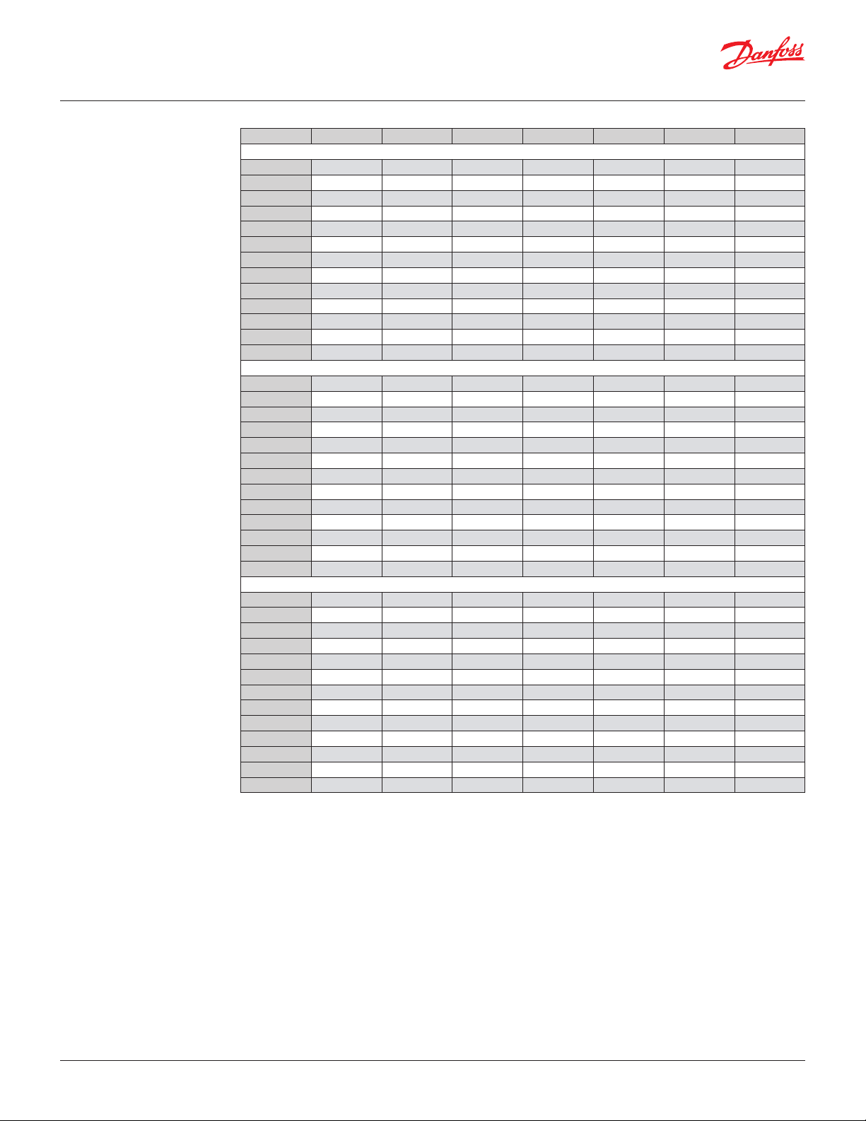
Rated capacity [TR]
For other refrigerants, refer
to Coolselector®2
Capacities are based on:
Pressure drop across valve: 3.00 psi
Liquid temperature: 100.0 °F
Subcooling: 10.0 °F
Evaporating temperature: 40.0 °F
Superheat: 0 °F
Capacities are based on:
Pressure drop across valve: 1.00 psi
EVR 25, EVR 32, EVR 40: 2.00 psi
Liquid temperature: 100.0 °F
Subcooling: 10.0 °F
Evaporating temperature: 40.0 °F
Superheat: 0 °F
Capacities are based on:
Pressure drop across valve: 3.00 psi
Condensing temperature: 100.0 °F
Subcooling: 10.0 °F
Hot gas temperature = tc +: 40.0 °F
Evaporating temperature: 40.0 °F
Superheat: 0 °F
Type R22/R407C R134a R404A/R507 R410A R32 R290 R600a
Liquid
EVR 2 0.92 0.85 0.59 0.86 1.25 1.03 1.06
EVR 3 1.66 1.54 1.07 1.55 2.26 1.85 1.91
EVR 4 4.18 3.87 2.68 3.9 5.69 4.65 4.81
EVR 6 5.47 5.07 3.51 5.11 7.44 6.08 6.3
EVR 8 6.52 6.03 4.18 6.08 8.87 7.25 7.5
EVR 10 11.5 10.64 7.38 10.73 15.64 12.78 13.24
EVR 15 17.71 16.39 11.37 16.53 24.09 19.68 20.39
EVR 18 23.18 21.46 14.88 21.64 31.53 25.77 26.69
EVR 20 36.76 34.04 23.6 34.32 50.01 40.87 42.33
EVR 22 41.93 38.82 26.92 39.14 57.04 46.61 48.28
EVR 25 60.19 55.72 38.64 56.18 – – –
EVR 32 102.85 95.23 66.03 96.01 – – –
EVR 40 148.77 137.75 95.51 138.88 – – –
Suction vapour
EVR 2 0.08 0.06 0.06 0.09 0.12 0.09 0.06
EVR 3 0.14 0.11 0.12 0.17 0.22 0.17 0.1
EVR 4 0.35 0.27 0.29 0.42 0.55 0.42 0.26
EVR 6 0.46 0.35 0.38 0.55 0.72 0.55 0.34
EVR 8 0.55 0.41 0.46 0.66 0.86 0.66 0.4
EVR 10 0.96 0.73 0.8 1.16 1.51 1.16 0.71
EVR 15 1.48 1.13 1.24 1.79 2.32 1.79 1.1
EVR 18 1.94 1.47 1.62 2.34 3.04 2.34 1.44
EVR 20 3.08 2.34 2.57 3.71 4.82 3.71 2.28
EVR 22 3.51 2.67 2.93 4.23 5.5 4.24 2.61
EVR 25 4.67 3.5 3.9 5.65 – – –
EVR 32 7.97 5.99 6.66 9.65 – – –
EVR 40 11.53 8.66 9.63 13.96 – – –
Hot gas
EVR 2 0.21 0.17 0.18 0.25 0.33 0.25 0.16
EVR 3 0.37 0.30 0.32 0.46 0.59 0.44 0.29
EVR 4 0.94 0.76 0.82 1.16 1.48 1.12 0.73
EVR 6 1.23 0.99 1.07 1.51 1.94 1.46 0.95
EVR 8 1.47 1.18 1.27 1.80 2.31 1.74 1.13
EVR 10 2.59 2.09 2.25 3.18 4.07 3.07 2.00
EVR 15 4.00 3.22 3.46 4.89 6.26 4.73 3.08
EVR 18 5.23 4.21 4.53 6.40 8.20 6.19 4.03
EVR 20 8.30 6.69 7.18 10.16 13.01 9.81 6.40
EVR 22 9.46 7.62 8.19 11.59 14.83 11.19 7.30
EVR 25 13.58 10.94 11.76 16.63 – – –
EVR 32 23.21 18.70 20.09 28.42 – – –
EVR 40 33.58 27.05 29.06 41.11 – – –
© Danfoss | DCS (az) | 2017.12
DKRCC.PD.BB0.F2.22 | 4
Data sheet | Solenoid valve, types EVR 2 - EVR 40 Version 2
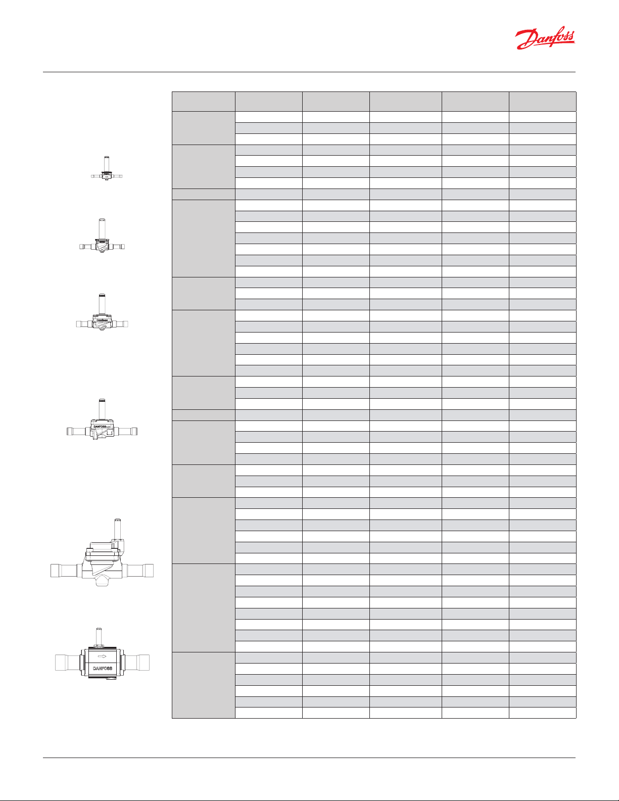
Ordering
EVR solder connection,
Normally Closed (NC)
- separate valve bodies
EVR 2 / EVR 3
EVR 4 / EVR 6 / EVR 8
EVR 10
EVR 15 / EVR 18 / EVR 20 / EVR 22
EVR 25
EVR 32 / EVR 40
Type Coil voltage
AC / DC
EVR 2
AC / DC
AC / DC – 6 No 032F1202
AC / DC
EVR 3
AC / DC
AC / DC – 6 No 032F1207
AC / DC – 10 No 032F1208
EVR 4 AC / DC
AC / DC
AC / DC
AC / DC – 10 No 032L1213
EVR 6
AC / DC – 12 No 032L1236
AC / DC
AC / DC
AC / DC
AC /DC
EVR 8
AC / DC
AC / DC
AC / DC
AC / DC – 12 No 032L1218
EVR 10
AC / DC
AC / DC
AC / DC
AC / DC
AC / DC
EVR 15
AC / DC
AC / DC
EVR 18 AC / DC
AC / DC
EVR 20
AC / DC
AC / DC 1 1⁄8 – No 032L1244
AC / DC – 28 No 032L1245
AC / DC 1 1⁄8 – No 032L7145
EVR 22
AC / DC 1 1⁄8 – Ye s 032L7137
AC / DC 1 3⁄8 – No 032L3267
AC / DC 1 1⁄8 – Ye s 032L2200
AC / DC 1 1⁄8 – No 032L2201
EVR 25
AC / DC – 28 Ye s 032L2205
AC / DC – 28 No 032L2206
AC / DC 1 3⁄8 – Ye s 032L2207
AC / DC 1 3⁄8 – No 032L2208
AC / DC 1 3⁄8 35 Yes 032L1105
AC / DC 1 3⁄8 35 No 032L1106
AC / DC 1 5⁄8 – Ye s 032L1103
EVR 32
AC / DC 1 5⁄8 – No 032L1104
AC / DC – 42 Ye s 032L1107
AC / DC – 42 No 032L1108
AC / DC 2 1⁄8 – No 032L1180
AC / DC 2 1⁄8 – Ye s 032L1181
AC / DC 1 5⁄8 – Ye s 032L1109
AC / DC 1 5⁄8 – No 032L1110
EVR 40
AC / DC – 42 Ye s 032L1113
AC / DC – 42 No 032L1114
AC / DC 2 1⁄8 – Ye s 032L1111
AC / DC 2 1⁄8 – No 032L1112
See separate data sheet for coils
Connection size
[in]
1
⁄4 – No 032F1201
1
⁄4 – No 032F7100
1
⁄4 – No 032F1206
3
⁄8 – No 032F1204
3
⁄8 – No 032L7110
3
⁄8 – No 032L1212
3
⁄8 – Yes 032L7116
1
⁄2 – No 032L1209
1
⁄2 – Yes 032L7144
5
⁄8 – No 032L7117
1
⁄2 – No 032L7121
1
⁄2 – Yes 032L7148
5
⁄8 – No 032L7122
3
⁄8 – No 032L7125
1
⁄2 – No 032L1217
1
⁄2 – Yes 032L1188
5
⁄8 16 No 032L1214
5
⁄8 – Ye s 032L7149
5
⁄8 16 No 032L1228
5
⁄8 16 Ye s 032L1227
7
⁄8 22 No 032L1225
7
⁄8 – Ye s 032L1004
7
⁄8 – No 032L1240
7
⁄8 – Ye s 032L1254
Connection size
[mm]
Manual operation Code no.
© Danfoss | DCS (az) | 2017.12
DKRCC.PD.BB0.F2.22 | 5
Data sheet | Solenoid valve, types EVR 2 - EVR 40 Version 2
Ordering
EVR solder connection,
Normally Open (NO)
- separate valve bodies
Note:
tube design
EVR 6
Ordering
EVR flare connection,
Normally Closed (NC)
- separate valve bodies
EVR 6
Type Coil voltage
EVR 6
EVR 10
EVR 15
EVR 20
EVR 22 AC 1 3⁄8 – No 032L3268
AC / DC
AC / DC – 10 No 032L1295
AC / DC
AC / DC – 12 No 032L1296
AC / DC
AC / DC
AC / DC
AC / DC 1 1⁄8 – No 032L1269
AC / DC – 28 No 032L1279
Connection size
[in]
3
⁄8 – No 032L1290
1
⁄2 – No 032L1291
5
⁄8 16 No 032L1299
7
⁄8 – No 032L3270
7
⁄8 – No 032L1260
Connection size
[mm]
Manual operation Code no.
See separate data sheet for coils
The normal range of coils can be used for the NO valves, with the exception of the double frequency versions of
110 V, 50/60 Hz and 220 V, 50/60 Hz.
Type Coil voltage
EVR 2 AC / DC
EVR 3
EVR 6
EVR 10
EVR 15
AC / DC
AC / DC
AC / DC
AC / DC
AC / DC
AC / DC
AC / DC
AC / DC
Connection size
[in]
1
⁄4 6 No 032F8056
1
⁄4 6 No 032F8107
3
⁄8 10 No 032F8116
3
⁄8 10 No 032L8072
1
⁄2 12 No 032L8079
1
⁄2 12 No 032L8095
5
⁄8 16 No 032L8098
5
⁄8 16 Yes 032L8100
5
⁄8 16 No 032L8101
Connection size
[mm]
Manual operation Code no.
See separate data sheet for coils
Ordering
EVR flare connection,
Normally Open (NO)
- separate valve bodies
Note:
tube design
Type Coil voltage
EVR 6 AC / DC
EVR 10 AC / DC
Connection size
[in]
3
⁄8 10 No 032L8085
1
⁄2 12 No 032L8090
Connection size
[mm]
Manual operation Code no.
See separate data sheet for coils
The normal range of coils can be used for the NO valves, with the exception of the double frequency versions of
110 V, 50/60 Hz and 220 V, 50/60 Hz.
Valve bodies are supplied without flare nuts.
Separate flare nuts:
– 1⁄4 in or 6 mm, code no. 011L1101
– 3⁄8 in or 10 mm, code no. 011L1135
– 1⁄2 in or 12 mm, code no. 011L1103
– 5⁄8 in or 16 mm, code no. 011L1167
© Danfoss | DCS (az) | 2017.12
DKRCC.PD.BB0.F2.22 | 6
Data sheet | Solenoid valve, types EVR 2 - EVR 40 Version 2
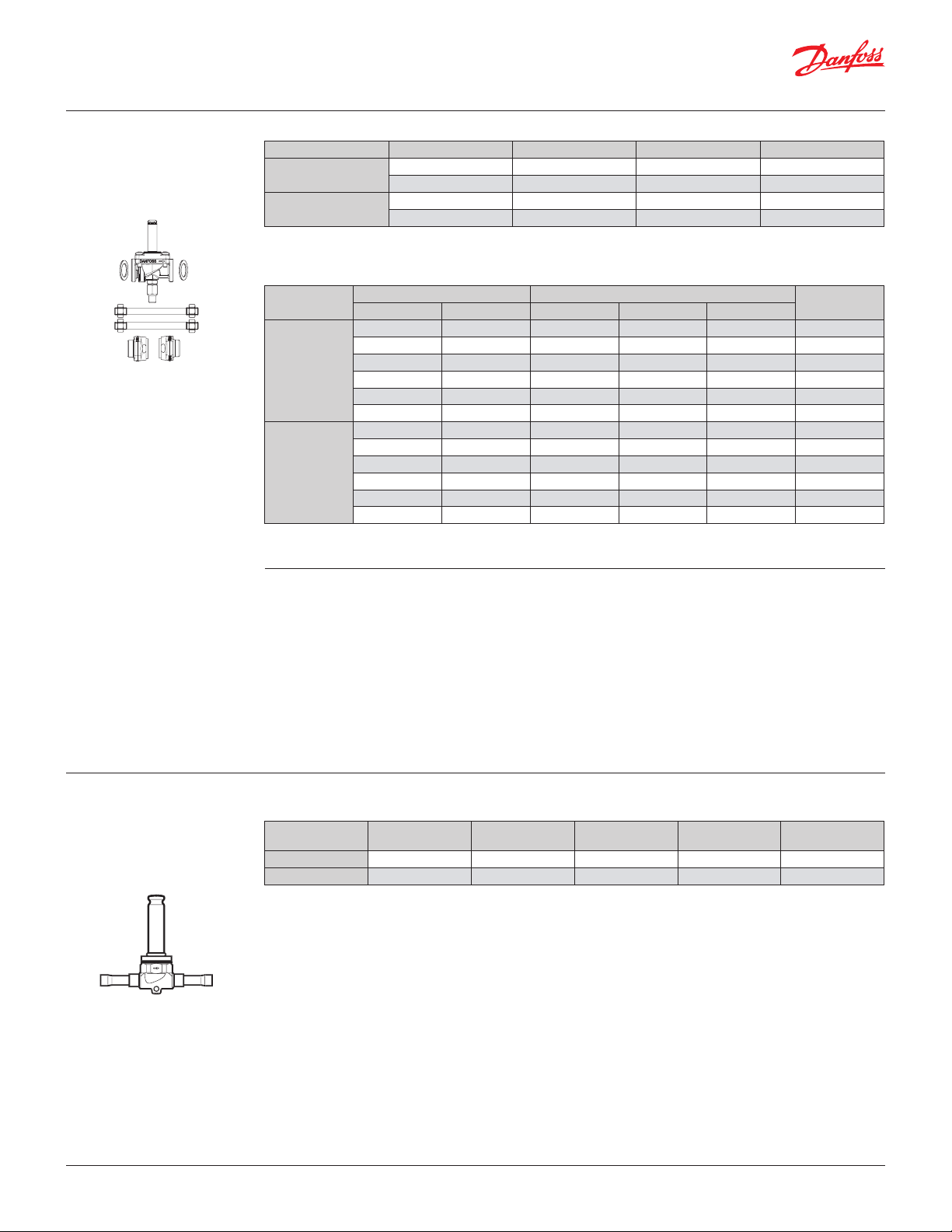
Ordering
EVR flange connection,
Normally Closed (NC)
- separate valve bodies
EVR 15
Type Coil voltage Connection Manual operation Code no.
EVR 15
EVR 20
AC / DC Flanges No 032L1224
AC / DC Flanges Ye s 032L1234
AC / DC Flanges No 032L1243
AC / DC Flanges Ye s 032L1253
See separate data sheet for coils
Flange sets
Type
EVR 15
EVR 20
Connection size Connection type
[in] [mm] Solder [in] Solder [mm] Weld [in]
1
⁄2 – – – Yes 027N1115
5
⁄8 – Yes – – 027L1117
– 16 – Yes – 027L1116
3
⁄4 – – – Yes 027N1120
7
⁄8 – Yes – – 027L1123
– 22 – Yes – 027L1122
3
⁄4 – – – Yes 027N1220
7
⁄8 – Yes – – 027L1223
– 22 – Yes – 027L1222
1 – – – Yes 027N1225
11
⁄8 – Yes – – 027L1229
– 28 – Yes – 027L1228
Code no.
See separate data sheet for coils
Ordering
EVRC solder connection,
Normally Closed (NC)
- separate valve bodies
Example
EVR 15 without manual operation,
code no. 032L1224
1
⁄2 in weld flange set,
code no. 027N1115
+ coil with terminal box, 220 V, 50 Hz,
code no. 018F6701
Type Coil voltage
EVRC 15 AC / DC
EVRC 20 AC / DC
See separate data sheet for coils
Connection size
[in]
5
⁄8 16 No 032L1255
7
⁄8 22 No 032L1258
Connection size
[mm]
Manual operation Code no.
© Danfoss | DCS (az) | 2017.12
DKRCC.PD.BB0.F2.22 | 7
Danfoss
18F66.10
Danfoss
18F67.10
Data sheet | Solenoid valve, types EVR 2 - EVR 40 Version 2
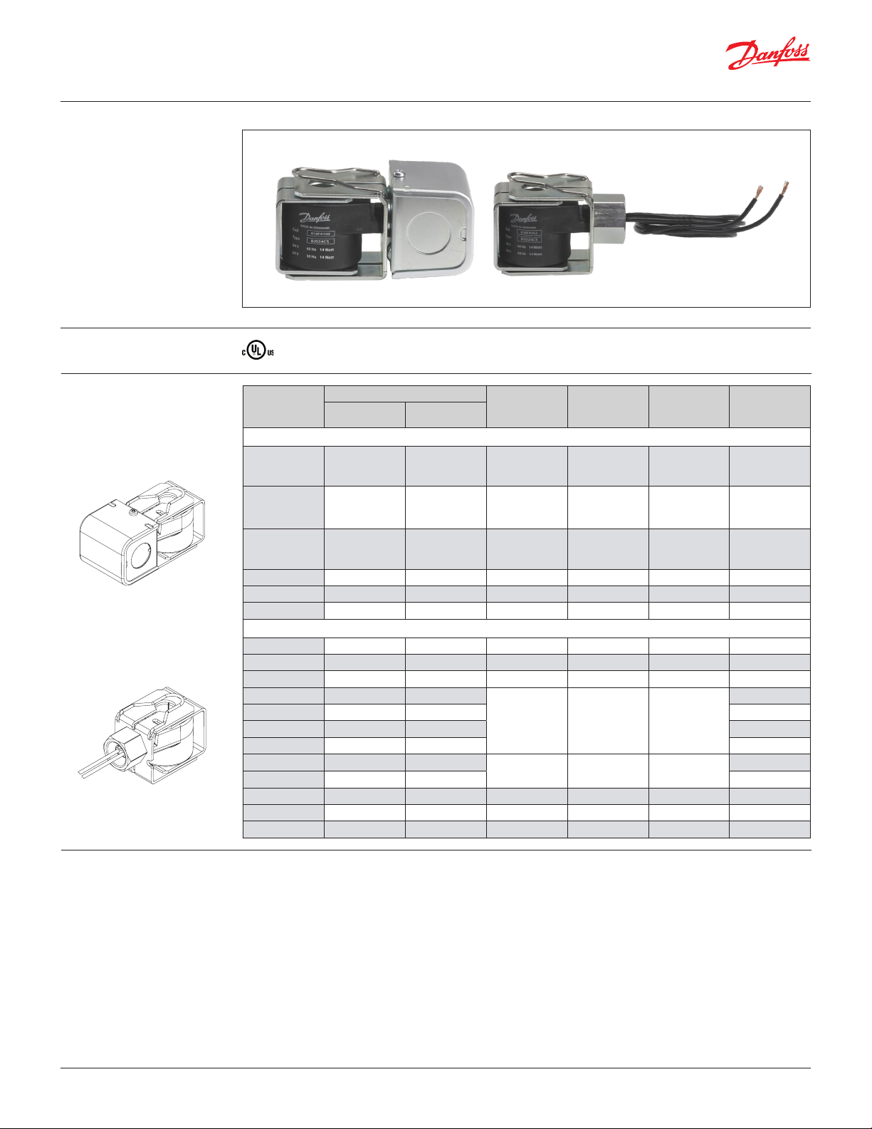
BJ and BX coils
Approvals
Ordering
Listed
Coil type
Junction box NEMA 2
BJ024CS 7 18 24 50 / 60 14 018F4100
BJ120CS
BJ240CS
BJ120BS 7 18 120 60 16 018F4130
BJ208BS 7 18 208 60 16 018F4132
BJ240BS 7 18 240 60 16 018F4134
Conduit boss NEMA 4
BX024CS 18 46 24 50 / 60 14 018F4102
BX024CS 71 180 24 50 / 60 14 018F4103
BX024CS 98 250 24 50 / 60 14 018F4104
BX120CS 18 46
BX120CS 36 91 018F4113
BX120CS 71 180 018F4114
BX120CS 98 250 018F4115
BX240CS 18 46
BX240CS 98 250 018F4123
BX120BS 98 250 120 60 16 018F4131
BX208BS 98 250 208 60 16 018F4133
BX240BS 98 250 240 60 16 018F4135
Wire length
[in] [cm]
7 18 110-120 60 15
7 18 110 50 16
7 18 208 – 240 60 14
7 18 230 50 17
Voltage
[V ] AC
110-120
110
208 – 240
230
Frequency
[Hz]
60
50
60
50
Power
consumption
[W]
15
16
14
17
Code no.
018F4110
018F4120
018F4112
018F4122
Technical data
© Danfoss | DCS (az) | 2017.12
Design
In accordance with UL 429
Power supply
Alternating current (AC)
Permissible voltage variation
Alternating current (AC):
50 Hz and 60 Hz: -10% – +15%
50/60 Hz: +/- 10%
Power consumption
Alternating current (AC): Inrush: 49 VA;
Holding: 28 VA. 14-17 W
Insulation of coil wire
Class H according to IEC 85
Connection
Junction box or Conduit boss
Enclosure. IEC 60529
Junction box NEMA 2 ~ IP 12–32
Conduit boss NEMA 4 ~ IP 54
Ambient temperature
-40 °F – 122 °F (-40 °C – 50 °C)
DKRCC.PD.BB0.F2.22 | 8
Danfoss
18F61
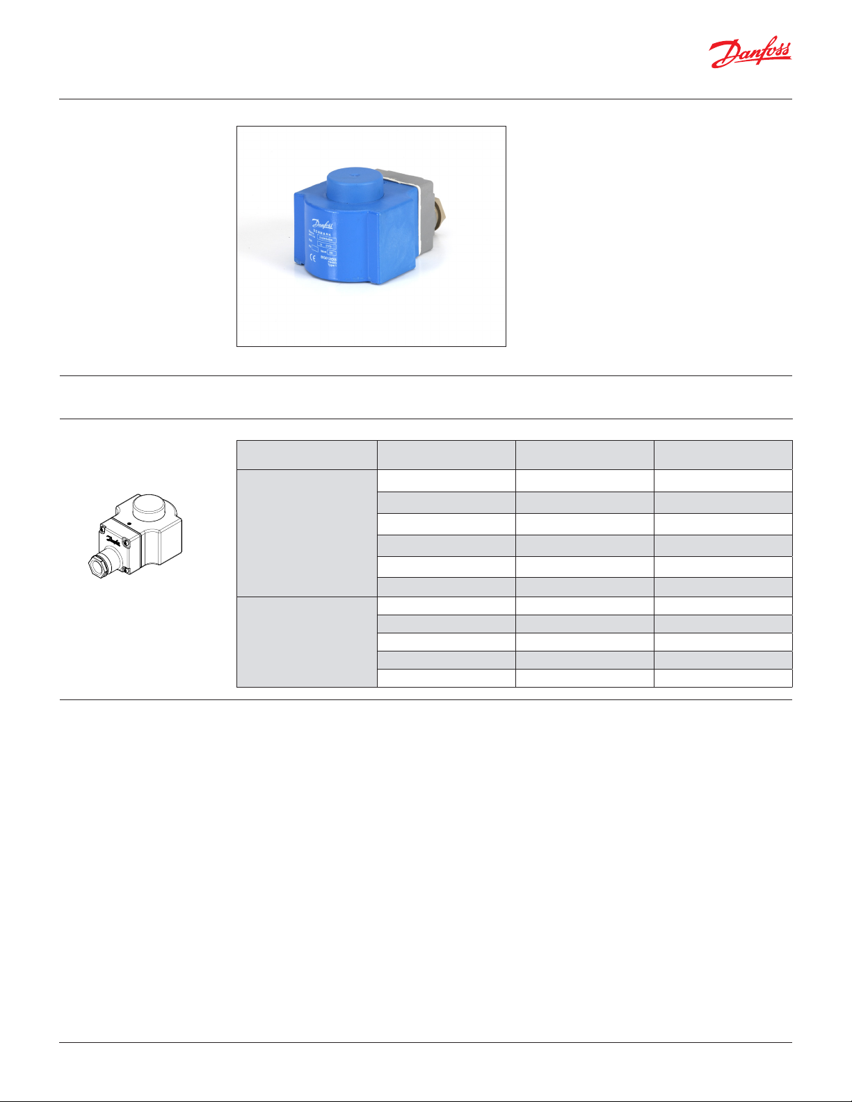
BG coils
Data sheet | Solenoid valve, types EVR 2 - EVR 40 Version 2
BG coils
Approvals
Ordering
Low Voltage Directive (LVD) 2014/35/EU
Valve type
EVR 2 to 8 (NC)
EVR 25 to 40 (NC/NO)
EVR 6 to 8 (NO)
EVR 10 to 22 (NC/NO)
EVRC 15 to 20
Voltage
[V] DC
y For high temperatures – class H insulated wire
y Encapsulated coils with long life time
y Wide range of coils
− from 12 V – 220 V DC
− with terminal box IP67 ~ NEMA 6
Power consumption
[W]
12 20 018F6856
24 16 018F6857
48 19 018F6859
110 16 018F6860
115 19 018F6861
220 20 018F6851
12 20 018F6886
24 20 018F6887
48 20 018F6889
110 20 018F6890
220 20 018F6881
Code no.
Technical data
© Danfoss | DCS (az) | 2017.12
Design
In accordance with VDE 0580
Power supply
Direct current (DC)
Permissible voltage variation
±10%
Power consumption
16-20 W
Insulation of coil wire
Class H according to IEC 85
Connection
Terminal box
Enclosure. IEC 529
IP 67 NEMA 6
Ambient temperature
-40 °F – 122 °F (-40 °C – 50 °C)
DKRCC.PD.BB0.F2.22 | 9

Data sheet | Solenoid valve, types EVR 2 - EVR 40 Version 2
Function
See Design and material
drawings for additional details
on the following pages
EVR solenoid valves are designed on two different
principles:
1. Direct operation
2. Servo operation
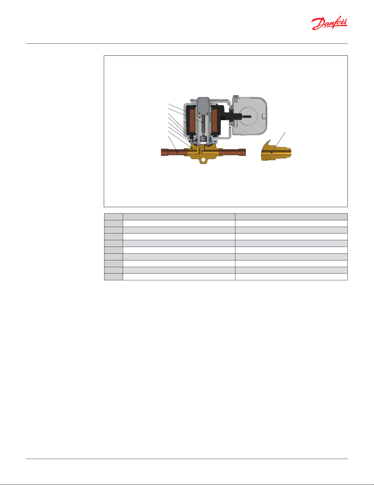
1. Direct operation (NC)
EVR 2 – EVR 3 are direct operated. The valves open
directly for full flow when the armature (3) moves
up into the magnetic field of the coil.
This means that the valves operate with a minimum
differential pressure of 0 bar.
The seat plate is fitted directly on the armature (3).
Inlet pressure acts from above on the armature and
the valve plate. Thus, the inlet pressure and spring
force act to close the valve when there is no current
in the coil.
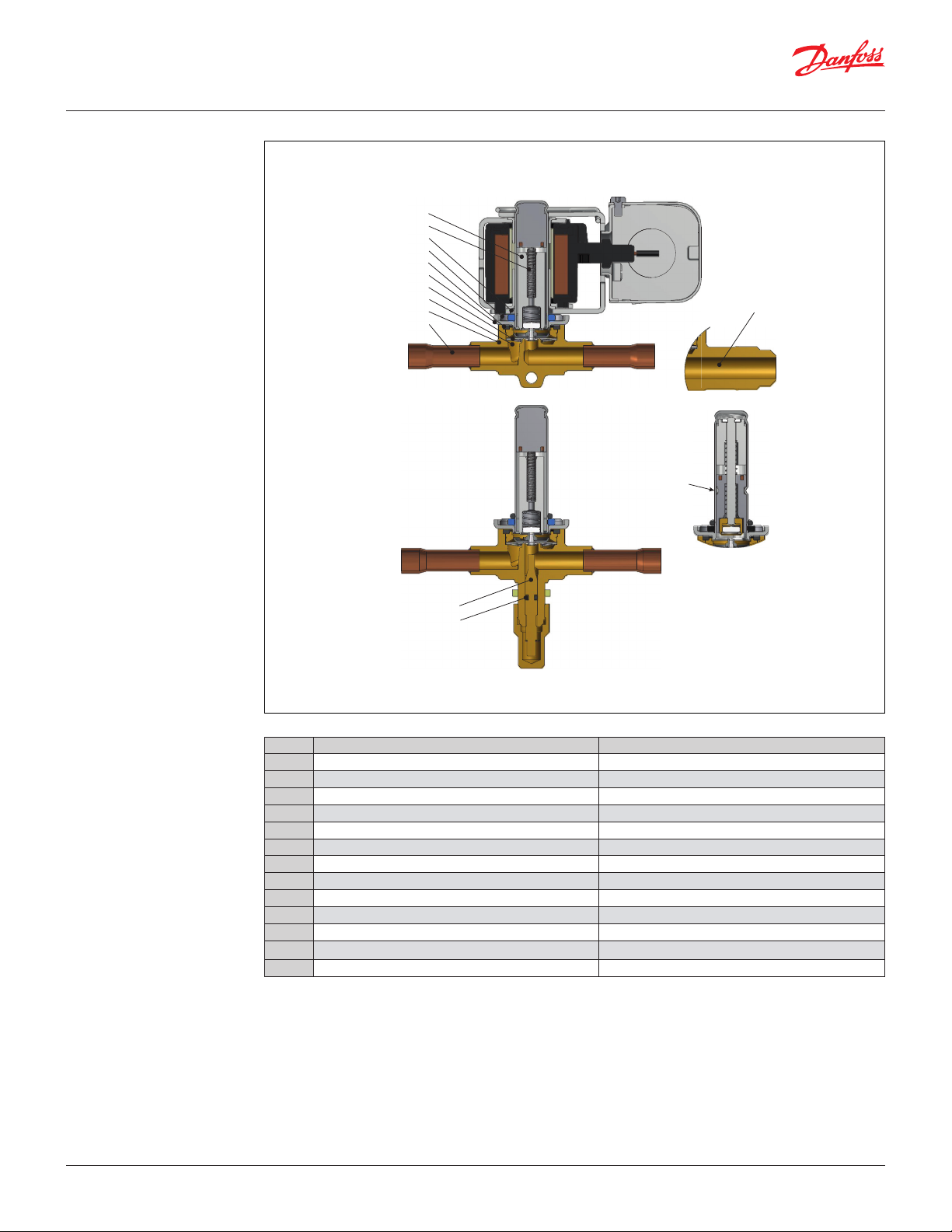
2. Servo operation (NC)
EVR 4 – EVR 22 are servo operated with a "floating"
diaphragm (4). The pilot orifice of stainless steel
is placed in the center of the diaphragm. The seat
plate is fitted directly to the armature (3). When
there is no current in the coil, the main orifice and
pilot orifice are closed. The pilot orifice and main
orifice are held closed by the armature spring force
and the differential pressure between inlet and
outlet sides.
When current is applied to the coil, the armature
is drawn up into the magnetic field and opens the
pilot orifice. This relieves the pressure above the
diaphragm, i.e. the space above the diaphragm
becomes connected to the outlet side of the valve.
The differential pressure between inlet and outlet
sides then presses the diaphragm away from the
main orifice and opens it for full flow. Therefore a
certain minimum differential pressure is necessary
to open the valve and keep it open. For EVR 4 – EVR
22 valves the minimum differential pressure for
safe operation is 0.03 bar.
When the current is switched off, the pilot orifice is
closed. Via the equalization holes in the
diaphragm, the pressure above the diaphragm
rises to the same value as the inlet pressure and the
diaphragm closes the main orifice.
EVR 25, EVR 32 and EVR 40 are servo operated
piston valves. The servo piston (16) with sealing
face closes against the valve seat by means of the
differential pressure between inlet and
outlet side of the valve and the force of the
compression spring. When the coil is switched on,
the pilot orifice opens. This relieves the pressure on
the piston spring side of the valve. The differential
pressure will then open the valve. The minimum
differential pressure for safe operation is 0.2 bar.
EVR (NO) has the opposite function to EVR (NC), i.e.
it is open with de-energized coil.
EVR (NO) is available with servo operation only.
3. Bi-flow operation with EVRC
EVRC is a servo operated solenoid valve with a
special diaphragm with built-in non-return valve.
The valve is for use in liquid lines in refrigeration
plants.
EVRC allows flow in both directions and can be
used in liquid lines in refrigeration plants with hot
gas or gas defrost.
During the refrigeration period EVRC works as
a normal solenoid valve, while during defrost it
allows the condensed liquid to return to the liquid
manifold.
During the defrosting period the coil for EVRC must
be energized.
4. Manual stem operation for EVR 6 - EVR 25 NC
EVR 6 - EVR 25 NC are available with optional
manual stem operation to manually force the
NC valve open when the coil is de-energized.
The protective cap should be removed and the
manual stem (12) should be rotated until the valve
is fully open. It takes approx. 6 cycles from fully
closed, to reach the fully open position.
After manual operation is completed, the valve
should manually be closed again and the protective
cap mounted.
Alternatively, all EVR NC and NO valves can be
manually operated by removing the coil and force
the valve open or closed by using a solenoid valve
tester (permanent magnet) code no. 018F0091.
© Danfoss | DCS (az) | 2017.12
DKRCC.PD.BB0.F2.22 | 10
11
Data sheet | Solenoid valve, types EVR 2 - EVR 40 Version 2
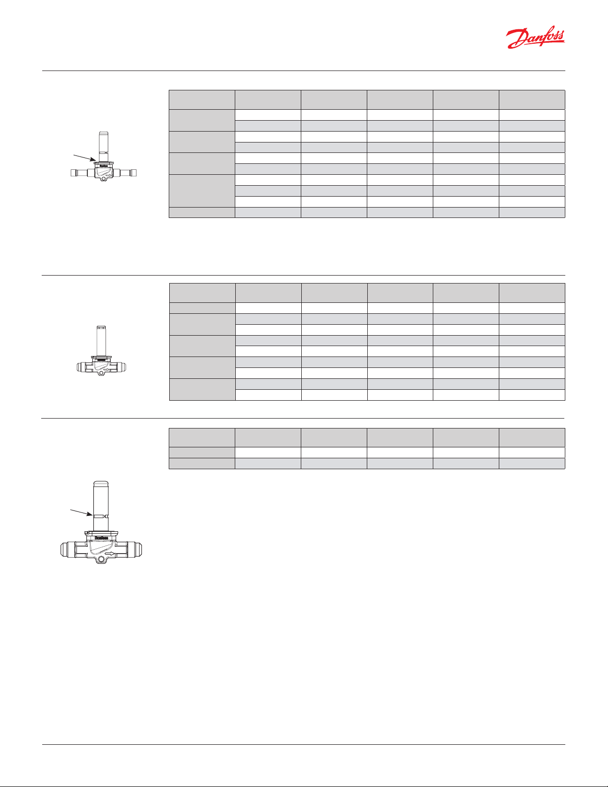
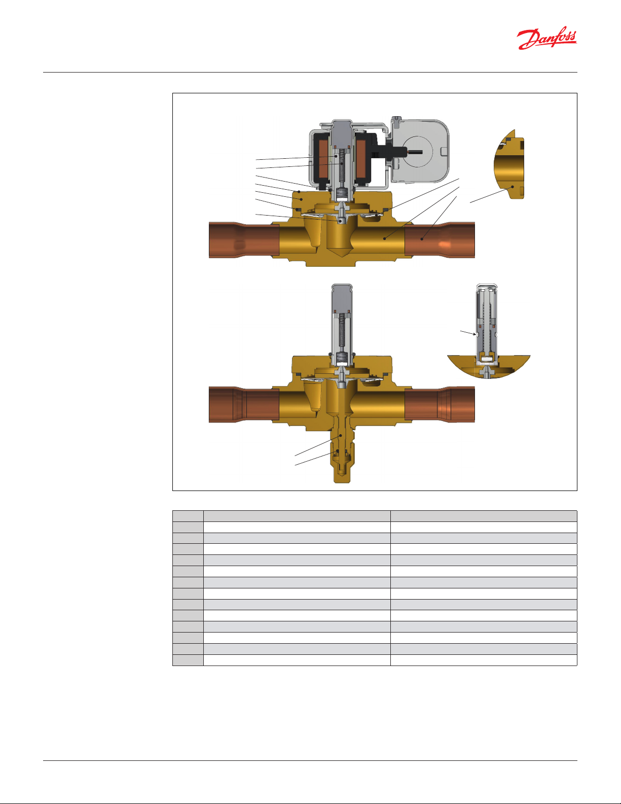
Design and
material specifications
EVR 2 - EVR 3
Solder and flare connection
3
6
9
8
7
2
1
10
Pos. no. Description Material
1 Valve assembly housing Brass, copper
2 Cover assembly Stainless steel
3 Armature assembly Stainless steel/PTFE
6 Armature spring Stainless steel
7 Seal Chloroprene rubber
8 Screw Stainless steel
9 O-ring EPDM Rubber
10 Solder connection Copper
11 Flare connection Brass
© Danfoss | DCS (az) | 2017.12
DKRCC.PD.BB0.F2.22 | 11
Data sheet | Solenoid valve, types EVR 2 - EVR 40 Version 2
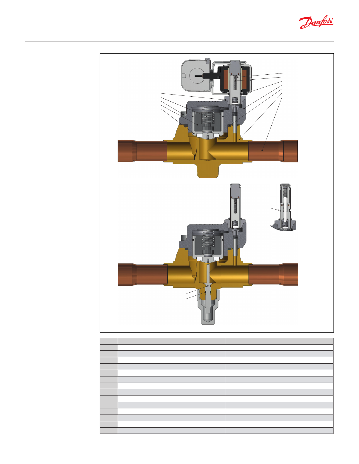
Design and
material specifications
EVR 4 - EVR 6 - EVR 8
Solder and flare connection
3
6
9
8
7
2
1
10
4
5
11
NO tube design
12
13
© Danfoss | DCS (az) | 2017.12
Pos. no. Description Material
1 Valve housing assembly Brass
2 Cover Stainless steel
3 Armature assembly Stainless steel/PTFE
4 Diaphragm assembly Stainless steel/PTFE
5 Suppor t washer Stainless steel
6 Armature spring Stainless steel
7 Seal Chloroprene rubber
8 Screws Stainless steel
9 O-ring EPDM rubber
10 Solder connection Copper
11 Flare connection Brass
12
13 O-ring Chloroprene rubber
1)
Manual stem is not available for EVR 4
Manual stem
1
Brass
DKRCC.PD.BB0.F2.22 | 12
Data sheet | Solenoid valve, types EVR 2 - EVR 40 Version 2
Design and
material specifications
EVR 10
Solder and flare connection
3
6
9
8
2
7
5
10
4
11
1
NO tube design
12
13
© Danfoss | DCS (az) | 2017.12
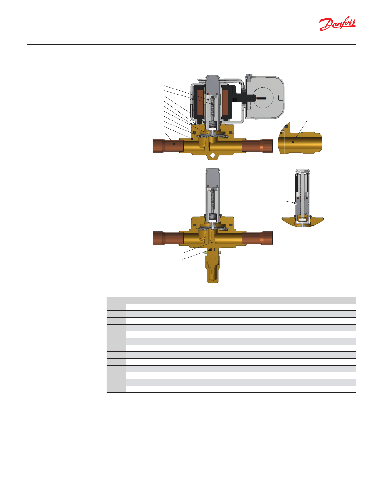
Pos. no. Description Material
1 Valve body Brass
2 Cover Brass
3 Armature assembly Stainless steel/PTFE
4 Diaphragm assembly Stainless steel/PTFE
5 Support washer Stainless steel
6 Armature spring Stainless steel
7 Seal Chloroprene rubber
8 Screws Stainless steel
9 O-ring EPDM rubber
10 Solder connection Copper
11 Flare connection Brass
12 Manual stem Brass
13 O-ring Chloroprene rubber
DKRCC.PD.BB0.F2.22 | 13
Data sheet | Solenoid valve, types EVR 2 - EVR 40 Version 2
Design and
material specifications
EVR 15 - EVR 18
Solder, flare, and flange
connection
3
6
5
9
8
4
2
7
1
10
14
11
NO tube design
12
13
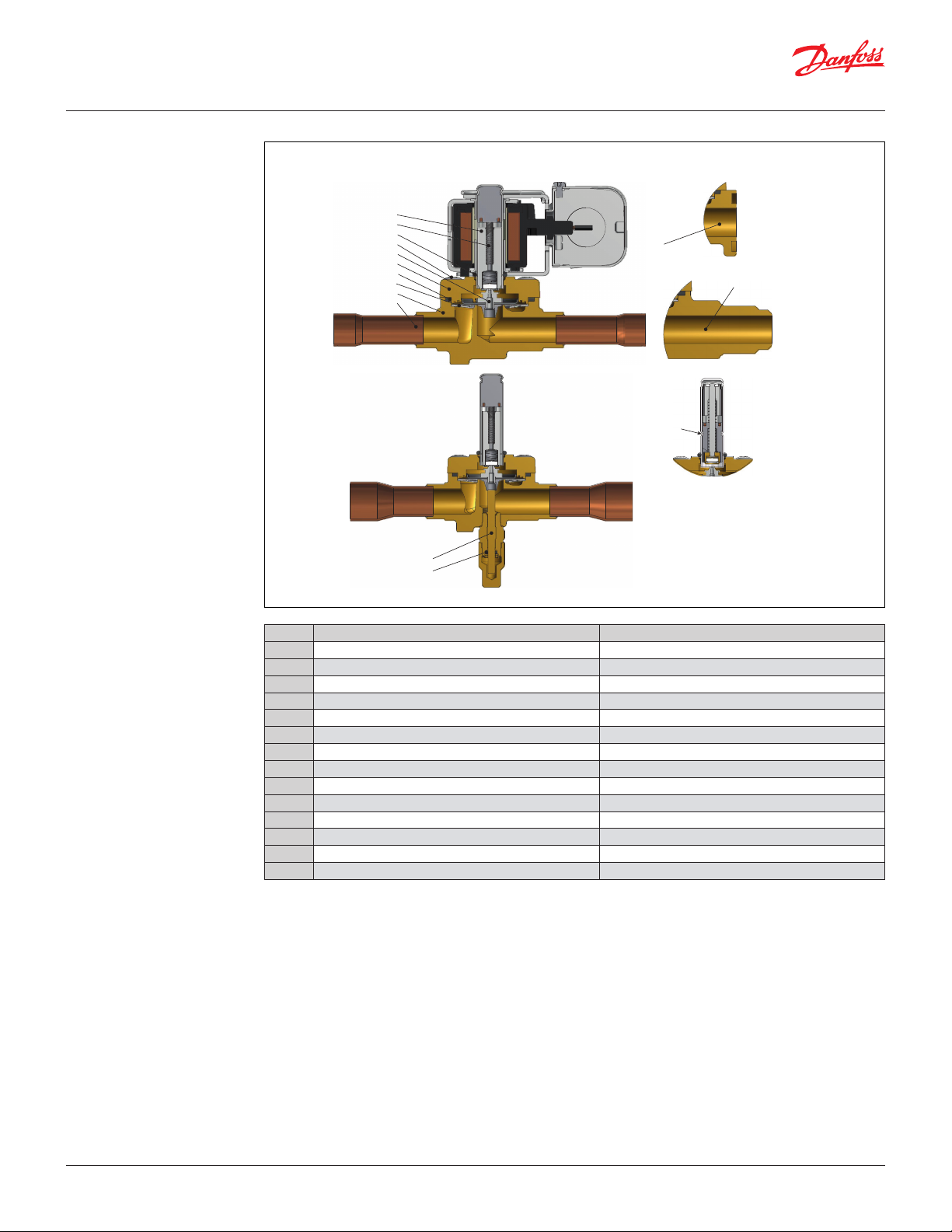
Pos. no. Description Material
1 Valve body Brass
2 Cover Brass
3 Armature assembly Stainless steel/PTFE
4 Diaphragm assembly Stainless steel/PTFE
5 Support washer Stainless steel
6 Armature spring Stainless steel
7 Seal Chloroprene rubber
8 Screws Stainless steel
9 O-ring EPDM rubber
10 Solder connection Copper
11 Flare connection Brass
12 Manual stem Brass
13 O-ring Chloroprene rubber
14 Flange connection Brass
© Danfoss | DCS (az) | 2017.12
DKRCC.PD.BB0.F2.22 | 14
Data sheet | Solenoid valve, types EVR 2 - EVR 40 Version 2
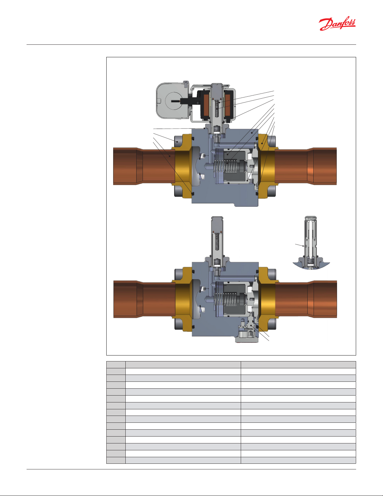
Design and
material specifications
EVR 20 - EVR 22
Solder and flange
connection
3
6
9
8
2
7
4
5
1
10
14
NO tube design
12
13
Pos. no. Description Material
1 Valve body Brass
2 Cover Brass
3 Armature assembly Stainless steel/PTFE
4 Diaphragm assembly Stainless steel/PTFE
5 Support washer Stainless steel
6 Armature spring Stainless steel
7 Seal Chloroprene rubber
8 Screws Stainless steel
9 O-ring EPDM rubber
10 Solder connection Copper
12 Manual stem Brass
13 O-ring Chloroprene rubber
14 Flange connection Brass
© Danfoss | DCS (az) | 2017.12
DKRCC.PD.BB0.F2.22 | 15
Data sheet | Solenoid valve, types EVR 2 - EVR 40 Version 2
Design and
material specifications
EVR 25
Solder connection
15
17
16
18
3
6
9
2
7
1
8
10
NO tube design
© Danfoss | DCS (az) | 2017.12
12
13
Pos. no. Description Material
1 Valve body Brass
2 Cover Cast iron
3 Armature assembly Stainless steel/PTFE
6 Armature spring Stainless steel
7 Gasket Chloroprene rubber
8 Screws Stainless steel
9 O-ring EPDM rubber
10 Solder connection Copper
12 Manual stem Brass
13 O-ring Chloroprene rubber
15 Gasket Aluminum
16 Insert Nylon
17 Piston spring Stainless steel
18 Piston Stainless steel
DKRCC.PD.BB0.F2.22 | 16
Data sheet | Solenoid valve, types EVR 2 - EVR 40 Version 2
Design and
material specifications
EVR 32 - EVR 40
Solder connection
15
8
10
7
3
6
9
16
1
17
2
18
7
NO tube design
13
12
Pos. no. Description Material
1 Valve body Cast iron
2 Cover Brass
3 Armature assembly Stainless steel
6 Armature spring Stainless steel
7 Gasket Chloroprene rubber
8 Screws Stainless steel
9 O-ring EPDM rubber
10 Solder connection Copper
12 Manual stem Brass
13 O-ring Chloroprene rubber
15 Gasket Aluminum
16 Insert Nylon
17 Piston spring Stainless steel
18 Piston Stainless steel
© Danfoss | DCS (az) | 2017.12
DKRCC.PD.BB0.F2.22 | 17
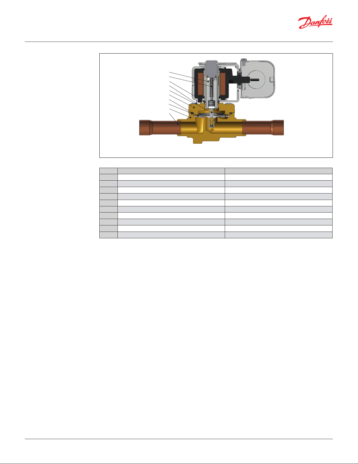
Data sheet | Solenoid valve, types EVR 2 - EVR 40 Version 2
Design and
material specifications
EVRC
Solder connection
Pos. no. Description Material
1 Valve body Brass
2 Cover Brass
3 Armature assembly Stainless steel/PTFE
4 Diaphram assembly Stainless steel/PTFE
5 Support washer Stainless steel
6 Armature spring Stainless steel
7 Gasket Chloroprene rubber
8 Screws Stainless steel
9 O-ring EPDM rubber
10 Solder connection Copper
3
6
9
8
4
7
5
10
2
1
© Danfoss | DCS (az) | 2017.12
DKRCC.PD.BB0.F2.22 | 18
H1
H2
Min. 2 9/16
H1
H2
Min. 2 9/16
W1
W1
W1
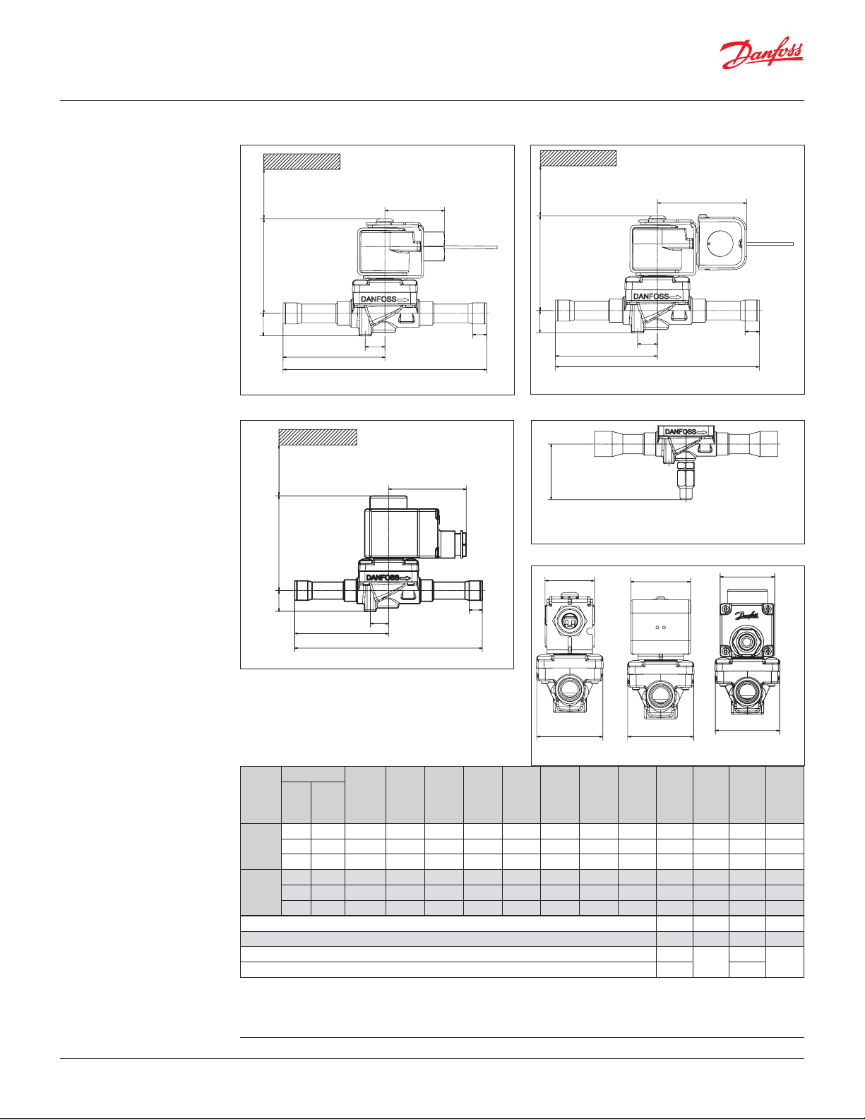
Data sheet | Solenoid valve, types EVR 2 - EVR 40 Version 2
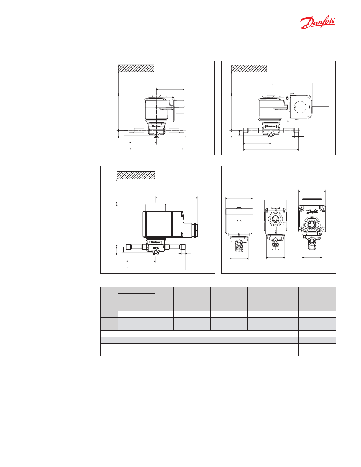
Dimensions and weights
EVR 2 - EVR 3
Solder connection
Conduit hub 1)
H3
Terminal box 3)
Min. 65 mm
Lc
L2
L1
L
Junction box 2)
Lc
H3
L1
L
L2
End view
Lc
H2
Type
EVR 2
EVR 3
H3
H1
L1
L
Connection
H
1
[in] [mm]
1
⁄4 6 0.55 2.87 0.35 3.98 1.99 0.28 – 1.34 – 0.35
1
⁄4 6 0.55 73 0.35 3.98 1.99 0.28 – 1.34 – 0.35
3
⁄8 10 0.55 73 0.35 4.61 2.30 0.31 – 1.34 – 0.37
[in]
H
[in]
L2
W
Conduit hub 1)
W
Junction box 2)
W
Terminal box 3)
Net
weight
H
2
[in]
L
3
[in]
[in]
L
L
1
[in]
2
L
C
[in]W[in]
W1 max.
[in]
without
coil
[lbs]
Cable coil 1) 1.93 – 1.81 –
DIN plug coil 2) 2.52 – 1.85 –
Terminal box coil 10 W 3) 2.83
Terminal box coil 12 / 20 W 3) 3.15 2.68
1.85
–
–
Conduit hub: 0.72 lbs
Junction box: 0.86 lbs
Terminal box: 1.10 lbs
For CAD models on individual code numbers, visit www.danfoss.com/products/categories/
© Danfoss | DCS (az) | 2017.12
DKRCC.PD.BB0.F2.22 | 19
H1
H2
Min. 2 9/16
H4
H1
H2
Min. 2 9/16
W1
W1
H1
H2
Min. 65 mm
W1
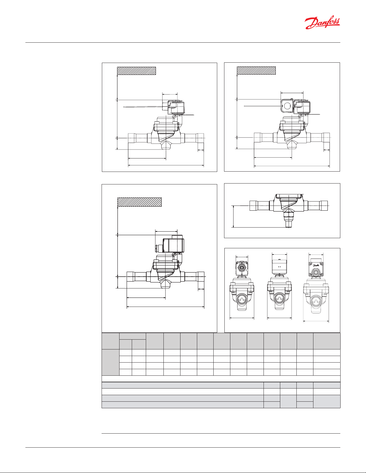
Data sheet | Solenoid valve, types EVR 2 - EVR 40 Version 2
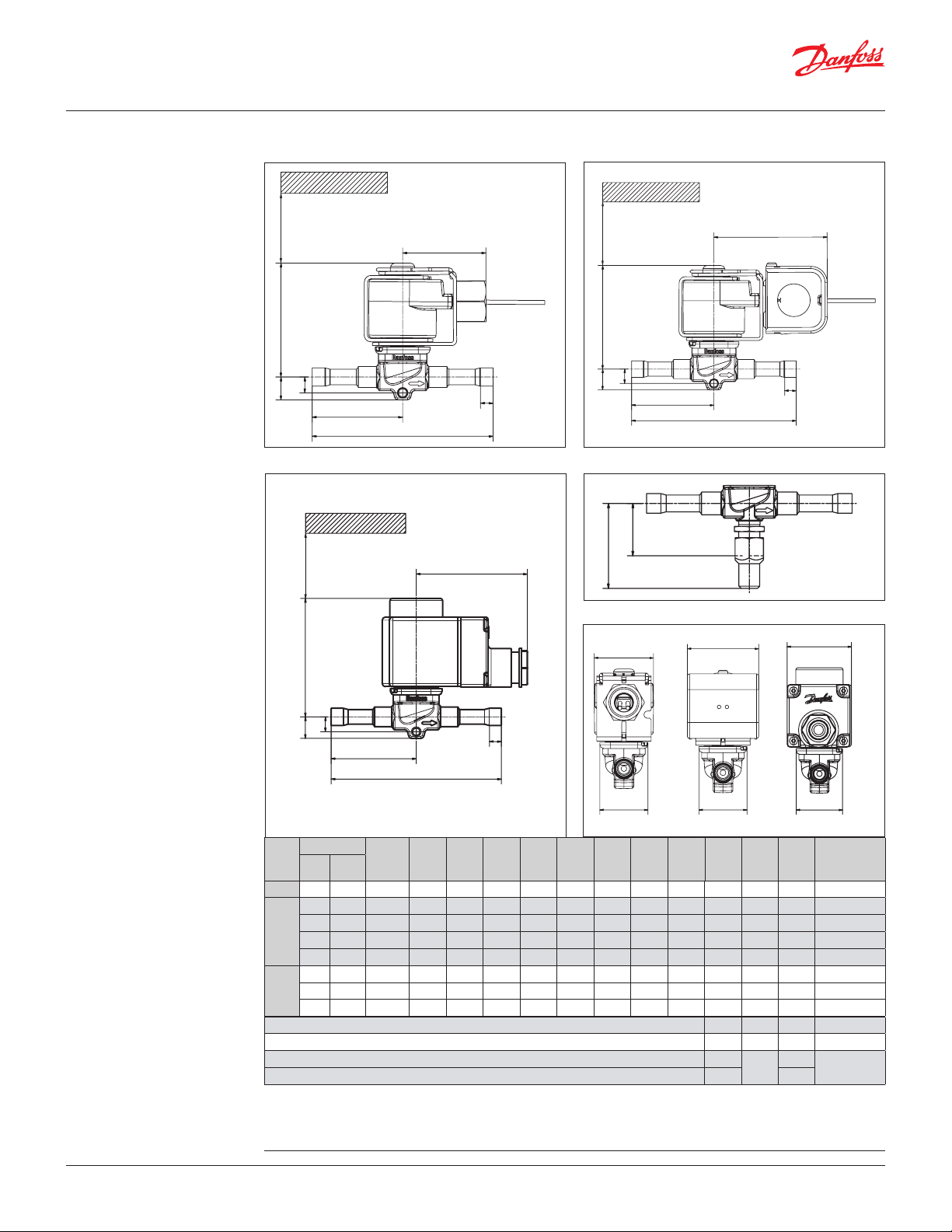
Dimensions and weights
EVR 4 - EVR 6 - EVR 8
Solder connection
Conduit hub 1)
H3
Terminal box 3)
Lc
L2
L1
L
Lc
Junction box 2)
H3
Manual stem
H5
Lc
L2
L1
L
© Danfoss | DCS (az) | 2017.12
End view
3
Connection Manual
Type
[in] [mm]
H
L1
L
opera-
tion
[in]
H
1
H
[in]
L2
W
L
[in]
1
Conduit hub 1)
H
H
2
3
[in]
[in]
4
H
5
[in]L[in]
W
Junction box 2)
L
L
2
C
[in]
[in]W[in]
Terminal box 3)
W1
max.
[in]
W
Net weight
without coil
[lbs]
EVR 43⁄8 10 No 0.55 3.07 0.39 — — 4.61 2.30 0.31 — 1.34 — 0.42
3
⁄8 10 Ye s 0.55 3.07 0.39 1.89 1.18 4.61 2.30 0.31 — 1.34 — 0.42
3
⁄8 10 No 0.55 3.07 0.39 — — 4.37 2.19 0.31 — 1.34 — 0.42
EVR 6
1
⁄2 12 Ye s 0.55 3.07 0.39 1.89 1.18 5 2.50 0.39 — 1.34 — 0.44
1
⁄2 12 No 0.55 3.07 0.39 — — 5 2.50 0.39 — 1.34 — 0.44
1
⁄2 12 Ye s 0.55 3.07 0.39 1.89 1.18 5 2.50 0.39 — 1.34 — 0.44
1
EVR 8
⁄2 12 No 0.55 3.07 0.39 — — 5 2.50 0.39 — 1.34 — 0.44
5
⁄8 16 No 0.55 3.07 0.39 — — 6.42 3.21 0.47 — 1.34 — 0.44
Cable coil 1) 1.93 — 1.81 —
DIN plug coil 2) 2.52 — 1.85 —
Terminal box coil 10 W 3) 2.83
Terminal box coil 12 / 20 W 3) 3.15 2.68
1.85
—
—
Net weight of coil (approx.)
Conduit hub: 0.72 lbs
Junction box: 0.86 lbs
Terminal box: 1.10 lbs
For 3D models, visit www.danfoss.com/products/categories/
DKRCC.PD.BB0.F2.22 | 20
H1
H2
Min. 2 9/16
H4
H1
H2
Min. 2 9/16
W1
W1
W1
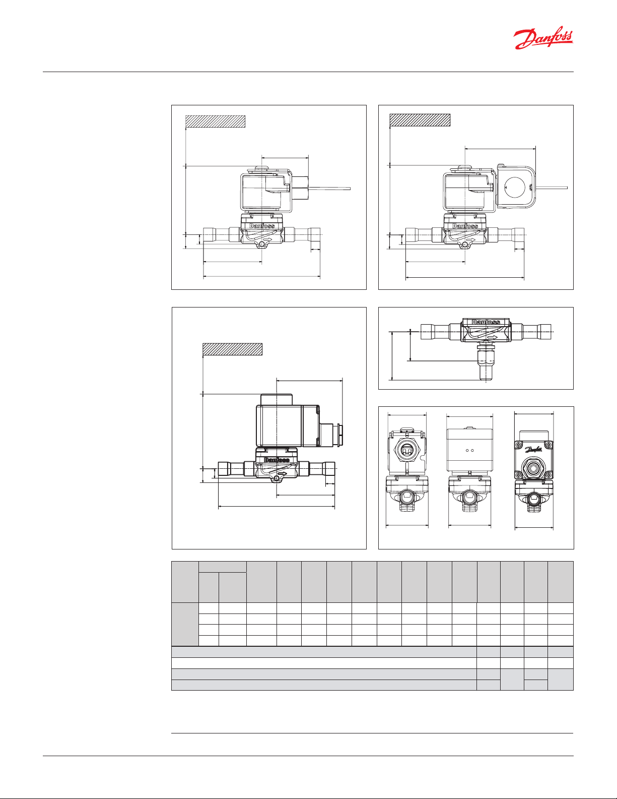
Data sheet | Solenoid valve, types EVR 2 - EVR 40 Version 2
Dimensions and weights
EVR 10
Solder connection
Conduit hub 1)
H3
Terminal box 3)
Min. 65 mm
Lc
L2
L1
L
Lc
Junction box 2)
H3
Manual stem
Lc
L2
L1
L
H5
End view
© Danfoss | DCS (az) | 2017.12
H2
H3
Type
EVR 10
H1
L
Connection
Manual
[in] [mm]
opera-
1
⁄2 12 Yes 0.59 3.23 0.39 1.89 1.14 5.04 2.52 0.39 – 1.81 – 0.86
3
⁄8 10 No 0.59 3.23 0.39 – – 4.65 2.32 – – 1.81 – 0.75
5
⁄8 16 No 0.59 3.23 0.39 – – 6.42 3.21 0.47 – 1.81 – 0.84
5
⁄8 16 Yes 0.59 3.23 0.39 1.89 1.14 6.42 3.21 0.47 – 1.81 – 0.88
tion
H
[in]
1
L2
L1
[in]
W
Conduit hub 1)
H
H
2
[in]
H
[in]
4
H
5
[in]L[in]
3
L
[in]
W
Junction box 2)
L
1
2
[in]
Terminal box 3)
L
C
[in]W[in]
W
W1
max.
[in]
weight
with-
out coil
Cable coil 1) 1.93 – 1.81 –
DIN plug coil 2) 2.52 – 1.85 –
Terminal box coil 10 W 3) 2.83
Terminal box coil 12 / 20 W 3) 3.15 2.68
1.85
–
Net weight of coil (approx.)
Conduit hub: 0.72 lbs
Junction box: 0.86 lbs
Terminal box: 1.10 lbs
For 3D models. visit www.danfoss.com/products/categories/
DKRCC.PD.BB0.F2.22 | 21
Net
[lbs]
–
H4
H1
H2
Min. 2 9/16
H1
H2
Min. 2 9/16
W1
W1
H1
H2
Min. 65 mm
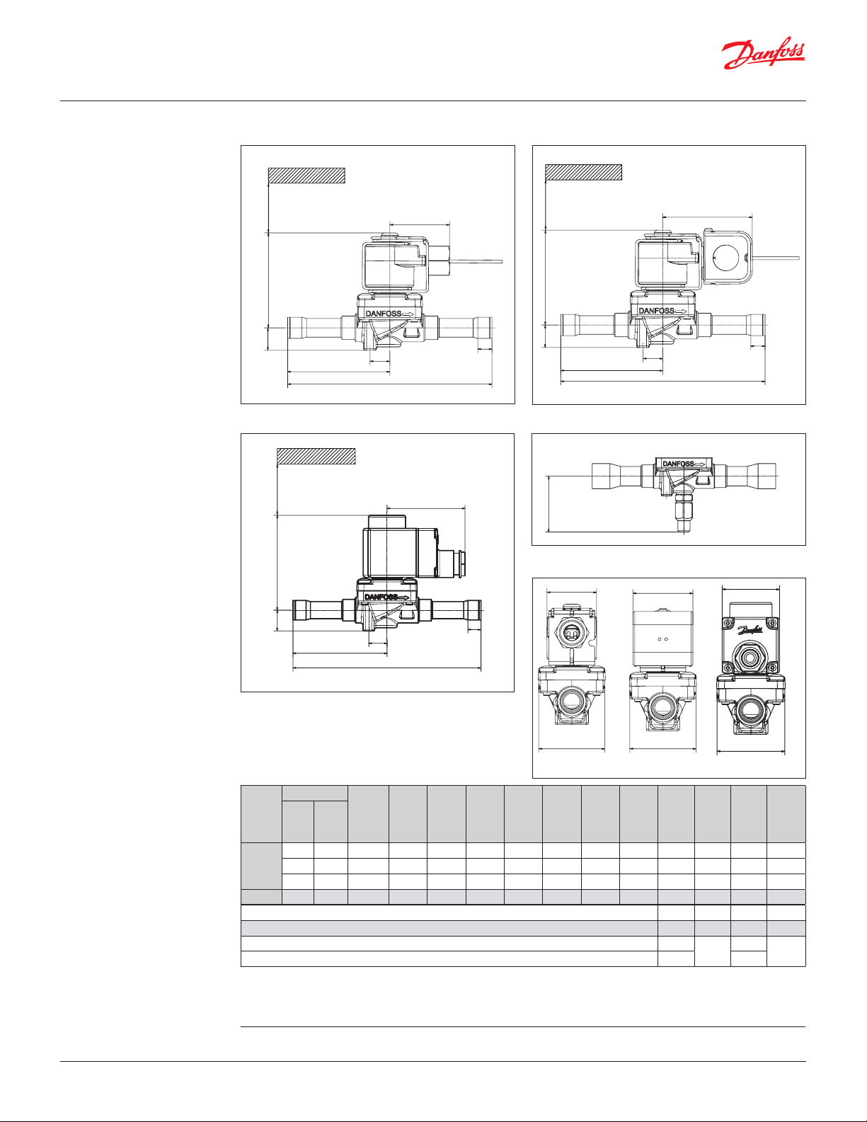
Data sheet | Solenoid valve, types EVR 2 - EVR 40 Version 2
Dimensions and weights
EVR 15 - EVR 18
Solder connection
Conduit hub 1)
Terminal box 3)
Junction box 2)
Lc
L3
L1
L
L2
L3
L1
L
Lc
L2
Manual stem
Lc
End view
W1
Type
EVR 15
L3
L1
L
Connection
Manual
[in] [mm]
5
⁄8 16 Yes 0.75 3.50 2.13 6.85 3.43 0.47 0.67 – 2.20 – 1.54
5
⁄8 16 No 0.75 3.50 – 6.85 3.43 0.47 0.67 – 2.20 – 1.54
7
⁄8 22 No 0.75 3.50 – 6.85 3.43 0.67 0.67 – 2.20 – 1.54
tion
opera-
H
[in]
1
H
[in]
2
L2
H
4
[in]L[in]
W
Conduit hub 1)
L
1
[in]
Junction box 2)
L
2
[in]
[in]
L
3
W
L
C
[in]W[in]
Terminal box 3)
W
W1
max.
[in]
Net
weight
without
coil
[lbs]
EVR 187⁄8 22 Yes 0.75 3.50 2.13 7.05 3.52 0.67 0.67 – 2.20 – 1.54
Cable coil 1) 1.93 – 1.81 –
DIN plug coil 2) 2.52 – 1.85 –
Terminal box coil 12 / 20 W 3) 3.15 2.68
Terminal box coil 10 W 3) 2.83
1.85
–
–
Net weight of coil (approx.)
Conduit hub: 0.72 lbs
Junction box: 0.86 lbs
Terminal box: 1.10 lbs
For 3D models, visit www.danfoss.com/products/categories/
© Danfoss | DCS (az) | 2017.12
DKRCC.PD.BB0.F2.22 | 22
H1
H2
Min. 2 9/16
H1
H2
Min. 2 9/16
W1
W1
H1
H2
Min. 65 mm
W1
Data sheet | Solenoid valve, types EVR 2 - EVR 40 Version 2
H4
Dimensions and weights
EVR 20 - EVR 22
Solder connection
Cable coil 1)
L1
Terminal box coil 3)
DIN plug coil 2)
Lc
L3
L2
L
L3
L1
L
Lc
L2
Manual stem
Lc
© Danfoss | DCS (az) | 2017.12
End view
H
[in]
2
L2
H
4
[in]L[in]
W
Conduit hub 1)
L
1
[in]
Junction box 2)
L
2
[in]
[in]
L
3
W
L
C
[in]W[in]
Terminal box 3)
–
W
W1
max.
[in]
1.85
weight
without
[lbs]
L3
L1
L
Connection
Manual
Type
EVR 20
opera-
[in] [mm]
7
⁄8 22 Yes 0.75 3.66 2.20 7.48 3.74 0.67 0.79 – 2.83 – 2.78
7
⁄8 22 No 0.75 3.66 – 7.48 3.74 0.67 0.79 – 2.83 – 2.78
tion
H
[in]
1
1 1⁄8 28 No 0.75 3.66 – 8.54 4.27 0.79 0.79 – 2.83 – 2.89
1 1⁄8 28 Yes 0.75 3.66 2.20 8.74 4.37 0.79 0.79 – 2.83 – 2.89
EVR 22
1 1⁄8 28 No 0.75 3.66 – 10.51 5.26 0.79 0.79 – 2.83 – 3.24
1 3⁄8 35 No 0.75 3.66 – 11.50 5.75 0.98 0.79 – 2.83 – 3.24
Cable coil 1) 1.93 – 1.81 –
DIN plug coil 2) 2.52 – 1.85 –
Terminal box coil 10 W 3) 2.83
Terminal box coil 12 / 20 W 3) 3.15 2.68
Net weight of coil (approx.)
Conduit hub: 0.72 lbs
Junction box: 0.86 lbs
Terminal box: 1.10 lbs
For 3D models, visit www.danfoss.com/products/categories/
DKRCC.PD.BB0.F2.22 | 23
Net
coil
–
H4
H1
H2
Min. 2 9/16
H1
H2
Min. 2 9/16
H1
H2
Min. 65 mm
W1
Data sheet | Solenoid valve, types EVR 2 - EVR 40 Version 2
W1
W1
Dimensions and weights
EVR 25
Solder connection
Conduit hub 1)
Terminal box 3)
Junction box 2)
Lc
L2
L1
L
L1
Lc
L2
L
Manual stem
Lc
© Danfoss | DCS (az) | 2017.12
End view
L2
L1
L
Type
Connection Manual
opera-
[in] [mm]
tion
H
[in]
W
Conduit hub 1)
H
[in]
2
H
4
[in]L[in]
[in]
1
L
L
1
2
[in]
W
Junction box 2)
L
C
[in]W[in]
Terminal box 3)
W1 max.
[in]
W
Net weight
without coil
1 1⁄8 28 Yes 1.54 5.43 2.80 10.04 5.02 0.79 – 3.23 – 5.89 *)
EVR 25
1 1⁄8 28 No 1.54 5.43 – 10.04 5.02 0.79 – 3.23 – 5.89 *)
1 3⁄8 35 Yes 1.54 5.43 2.80 11.06 5.53 0.98 – 3.23 – 6.17 *)
1 3⁄8 35 No 1.54 5.43 – 11.06 5.53 0.98 – 3.23 – 6.17 *)
*) Manual stem: +0.13 lbs
Cable coil 1) 1.93 – 1.81 –
DIN plug coil 2) 2.52 – 1.85 –
Terminal box coil 10 W 3) 2.83
Terminal box coil 12 / 20 W 3) 3.15 2.68
1.85
–
Net weight of coil (approx.)
Conduit hub: 0.72 lbs
Junction box: 0.86 lbs
Terminal box: 1.10 lbs
For 3D models, visit www.danfoss.com/products/categories/
DKRCC.PD.BB0.F2.22 | 24
[lbs]
–

H4
H2
H1
Min. 2 9/16
H2
H1
Min. 2 9/16
W1
W1
H2
H1
Min. 65 mm
W1
Data sheet | Solenoid valve, types EVR 2 - EVR 40 Version 2
Dimensions and weights
EVR 32 - EVR 40
Solder connection
Conduit hub 1)
Terminal box 3)
Junction box 2)
Lc
L2
L1
L
Lc
L2
L1
L
Manual stem
Lc
© Danfoss | DCS (az) | 2017.12
End view
H
[in]
2
L2
H
4
[in]L[in]
W
Conduit hub 1)
L
1
[in]
Junction box 2)
L
2
[in]
W
L
C
[in]W[in]
W1 max.
–
W
Terminal box 3)
Net weight
without coil
[in]
1.85
[lbs]
L1
L
Connection Manual
Type
[in] [mm]
opera-
tion
H
[in]
1
1 3⁄8 35 Yes – 4.37 2.17 11.02 5.51 0.98 – 3.19 – 9.48
1 3⁄8 35 No 2.01 4.37 – 11.02 5.51 0.98 – 3.19 – 9.48
EVR 32
1 5⁄8 42 Yes – 4.37 2.17 11.02 5.51 1.14 – 3.19 – 9.70
1 5⁄8 42 No 2.01 4.37 – 11.02 5.51 1.14 – 3.19 – 9.70
2 1⁄8 – Ye s – 4.37 2.17 11.02 5.51 1.34 – 3.15 – 10.08
2 1⁄8 – No 2.01 4.37 – 11.02 5.51 1.34 – 3.15 – 10.08
1 5⁄8 42 Yes – 4.37 2.17 11.02 5.51 1.14 – 3.19 – 9.70
EVR 40
1 5⁄8 42 No 2.01 4.37 – 11.02 5.51 1.14 – 3.19 – 9.70
2 1⁄8 – Ye s – 4.37 2.17 11.02 5.51 1.34 – 3.15 – 10.08
2 1⁄8 – No 2.01 4.37 – 11.02 5.51 1.34 – 3.15 – 10.08
Cable coil 1) 1.93 – 1.81 –
DIN plug coil 2) 2.52 – 1.85 –
Terminal box coil 10 W 3) 2.83
Terminal box coil 12 / 20 W 3) 3.15 2.68
Net weight of coil (approx.)
Conduit hub: 0.72 lbs
Junction box: 0.86 lbs
For 3D models. visit www.
danfoss.com/products/categories/
Terminal box: 1.10 lbs
DKRCC.PD.BB0.F2.22 | 25
–

H1
H2
Min. 2 9/16
H1
H2
Min. 2 9/16
W1
W1
H1
H2
Min. 65 mm
Data sheet | Solenoid valve, types EVR 2 - EVR 40 Version 2
Dimensions [mm]
and weights [kg]
EVRC 15
Solder connection
Conduit hub 1)
Lc
L3
L1
L
L2
Junction box 2)
Terminal box 3) End view
Lc
Lc
L3
L1
L
L2
W1
L3
L1
L
L2
W
Conduit hub 1)
W
Junction box 2)
W
Terminal box 3)
Connection
Type
[in] [mm]
Manual
opera-
tion
[in]
H
1
H
2
[in]L[in]
[in]
L
L
L
1
2
[in]
[in]
3
L
C
[in]W[in]
W1 max.
[in]
Net weight
without coil
[lbs]
EVRC 155⁄8 16 No 0.75 3.50 6.85 3.43 0.47 0.67 – 2.20 – 1.54
Cable coil 1) 1.93 – 1.81 –
DIN plug coil 2) 2.52 – 1.85 –
Terminal box coil 10 W 3) 2.83
Terminal box coil 12 / 20 W 3) 3.15 2.68
1.85
–
–
Net weight of coil (approx.)
Conduit hub: 0.72 lbs
Junction box: 0.86 lbs
Terminal box: 1.10 lbs
For 3D models, visit www.danfoss.com/products/categories/
© Danfoss | DCS (az) | 2017.12
DKRCC.PD.BB0.F2.22 | 26

H1
H2
Min. 2 9/16
H1
H2
Min. 2 9/16
W1
W1
H1
H2
Min. 65 mm
W1
Data sheet | Solenoid valve, types EVR 2 - EVR 40 Version 2
Dimensions and weights
EVRC 20
Solder connection
Conduit hub 1)
Lc
L3
L1
L
L2
Junction box 2)
Terminal box 3) End view
Lc
Lc
L3
L1
L
L2
L3
L1
L
L2
W
Conduit hub 1)
W
Junction box 2)
W
Terminal box 3)
Connection
Type
[in] [mm]
Manual
opera-
tion
H
[in]
1
H
2
[in]L[in]
L
[in]
L
L
1
2
[in]
[in]
3
L
C
[in]W[in]
W1 max.
[in]
Net weight
without coil
[lbs]
EVRC 207⁄8 22 No 0.75 3.66 7.48 3.74 0.67 0.79 – 2.83 – 2.78
Cable coil 1) 1.93 – 1.81 –
DIN plug coil 2) 2.52 – 1.85 –
Terminal box coil 10 W 3) 2.83
Terminal box coil 12 / 20 W 3) 3.15 2.68
1.85
–
–
Net weight of coil (approx.)
Conduit hub: 0.72 lbs
Junction box: 0.86 lbs
Terminal box: 1.10 lbs
For 3D models, visit www.danfoss.com/products/categories/
© Danfoss | DCS (az) | 2017.12
DKRCC.PD.BB0.F2.22 | 27

H1
H2
Min. 2 9/16
H1
H2
Min. 2 9/16
W1
W1
H1
H2
Min. 2 9/16
H1
H2
Min. 2 9/16
H1
H2
Min. 65 mm
W1
Data sheet | Solenoid valve, types EVR 2 - EVR 40 Version 2
Dimensions and weights
EVR 2 - EVR 3
Flare connection
Conduit hub 1)
H3
H3
Terminal box 3)
Junction box 2)
c
c
L
L
H3
H3
L1
L1
L
L
L1
L1
L
L
c
c
L
L
End view
Lc
3
Type
EVR 2
EVR 3
H
L1
L
W
Conduit hub 1)
Junction box 2)
W
Connection
H
1
[in] [mm]
1
⁄4 6 0.55 2.87 0.35 2.95 1.48 – 1.34 – 0.40
1
⁄4 6 0.55 2.87 0.35 2.95 1.48 – 1.34 – 0.40
3
⁄8 10 0.55 2.87 0.35 2.95 1.48 – 1.34 – 0.40
[in]
H
[in]
H
2
[in]
3
[in]
L
[in]
L
L
1
[in]
W
C
[in]
W
Terminal box 3)
weight
[in]
without
[lbs]
W1 max.
Net
coil
Cable coil 1) 1.93 – 1.81 –
DIN plug coil 2) 2.52 – 1.85 –
Terminal box coil 10 W 3) 2.83
Terminal box coil 12 / 20 W 3) 3.15 2.68
–
1.85
–
Net weight of coil (approx.)
Conduit hub: 0.72 lbs
Junction box: 0.86 lbs
Terminal box: 1.10 lbs
For 3D models, visit www.danfoss.com/products/categories/
© Danfoss | DCS (az) | 2017.12
DKRCC.PD.BB0.F2.22 | 28

W1
Data sheet | Solenoid valve, types EVR 2 - EVR 40 Version 2
H1
H2
Min. 2 9/16
H1
H2
Min. 2 9/16
W1
W1
Dimensions and weights
EVR 6
Flare connection
Conduit hub 1)
H3
Terminal box 3)
Min. 65 mm
Junction box 2)
Lc
H3
L1
L
L1
L
Lc
End view
Lc
H2
Type
EVR 6
H3
H1
L1
L
Connection
H
[in] [mm]
3
⁄8 10 0.55 3.03 0.39 3.23 1.61 – 1.34 – 0.46
1
⁄2 12 0.55 3.03 0.39 3.46 1.73 – 1.34 – 0.49
[in]
H
1
[in]
H
2
[in]
3
W
Conduit hub 1)
L
[in]
L
[in]
Junction box 2)
1
[in]
W
W
Terminal box 3)
Net
weight
L
W
C
W1 max.
[in]
[in]
without
coil
[lbs]
Cable coil 1) 1.93 – 1.81 –
DIN plug coil 2) 2.52 – 1.85 –
Terminal box coil 10 W 3) 2.83
Terminal box coil 12 / 20 W 3) 3.15 2.68
–
1.85
–
Net weight of coil (approx.)
Conduit hub: 0.72 lbs
Junction box: 0.86 lbs
Terminal box: 1.10 lbs
For 3D models, visit www.danfoss.com/products/categories/
© Danfoss | DCS (az) | 2017.12
DKRCC.PD.BB0.F2.22 | 29

H1
H2
Min. 2 9/16
H1
H2
Min. 2 9/16
H1
H2
Min. 65 mm
W1
W1
Data sheet | Solenoid valve, types EVR 2 - EVR 40 Version 2
Dimensions and weights
EVR 10
Flare connection
H3
Terminal box 3)
Junction box 2)Conduit hub 1)
Lc
H3
L1
L
L1
L
Lc
End view
W1
Lc
© Danfoss | DCS (az) | 2017.12
Type
EVR 10
H3
L1
L
Connection
H
1
[in] [mm]
1
⁄2 12 0.59 3.23 0.39 4.06 2.03 – 1.81 – 0.97
5
⁄8 16 0.59 3.23 0.39 4.33 2.17 – 1.81 – 0.99
[in]
H
[in]
H
2
[in]
3
W
Conduit hub 1)
L
[in]
L
[in]
Junction box 2)
1
[in]
W
W
Terminal box 3)
weight
L
W
C
W1 max.
[in]
[in]
without
[lbs]
Cable coil 1) 1.93 – 1.81 –
DIN plug coil 2) 2.52 – 1.85 –
Terminal box coil 10 W 3) 2.83
Terminal box coil 12 / 20 W 3) 3.15 2.68
–
1.85
Net weight of coil (approx.)
Conduit hub: 0.72 lbs
Junction box: 0.86 lbs
Terminal box: 1.10 lbs
For 3D models, visit www.danfoss.com/products/categories/
DKRCC.PD.BB0.F2.22 | 30
Net
coil
–

H1
H2
Min. 2 9/16
H1
H2
Min. 2 9/16
H1
H2
Min. 65 mm
H4
W1
W1
Data sheet | Solenoid valve, types EVR 2 - EVR 40 Version 2
Dimensions and weights
EVR 15
Flare connection
Conduit hub 1)
Lc
L3
L1
L
Junction box 2)
Terminal box 3) Manual stem
Lc
Lc
L3
L1
L
© Danfoss | DCS (az) | 2017.12
End view
W1
L3
L1
L
Type
EVR 15
W
Conduit hub 1)
Connection Manual
opera-
[in] [mm]
5
⁄8 16 Yes 0.75 3.50 2.09 5.16 2.58 0.67 – 2.20 – 1.72
5
⁄8 16 No 0.75 3.50 – 5.16 2.58 0.67 – 2.20 – 1.72
tion
H
[in]
H
[in]
2
H
4
[in]L[in]
1
[in]
L
L
1
3
[in]
W
Junction box 2)
L
C
[in]W[in]
Terminal box 3)
W1 max.
[in]
W
Net weight
without coil
Cable coil 1) 1.93 – 1.81 –
DIN plug coil
Terminal box coil 10 W 3) 2.83
Terminal box coil 12 / 20 W 3) 3.15 2.68
2)
2.52 – 1.85 –
1.85
–
Net weight of coil (approx.)
Conduit hub: 0.72 lbs
Junction box: 0.86 lbs
Terminal box: 1.10 lbs
For 3D models, visit www.danfoss.com/products/categories/
DKRCC.PD.BB0.F2.22 | 31
[lbs]
–

H4
H1
H2
Min. 2 9/16
H1
H2
Min. 2 9/16
W1
W1
Min. 65 mm
H2
H1
W1
Data sheet | Solenoid valve, types EVR 2 - EVR 40 Version 2
Dimensions and weights
EVR 15
Flange connection
Conduit hub 1)
Terminal box 3)
Junction box 2)
Lc
L3
L1
L
L3
L1
L
Lc
Manual stem
© Danfoss | DCS (az) | 2017.12
Lc
End view
L3
L1
L
W
Terminal box 3)
Net weight
without coil
Type
EVR 15
W
Conduit hub 1)
W
Junction box 2)
Manual
opera-
tion
H
[in]
1
[in]
H
H
2
[in]
L
4
[in]
[in]
L
L
1
[in]
L
3
[in]
W
[in]
W1 max.
[in]
C
Yes 0.75 3.50 2.09 4.96 1.33 0.67 – 3.15 – 1.41
No 0.75 3.50 – 4.96 1.33 0.67 – 3.15 – 1.41
Cable coil 1) 1.93 – 1.81 –
DIN plug coil 2) 2.52 – 1.85 –
Terminal box coil 10 W 3) 2.83
Terminal box coil 12 / 20 W 3) 3.15 2.68
1.85
–
Net weight of coil (approx.)
Conduit hub: 0.72 lbs
Junction box: 0.86 lbs
Terminal box: 1.10 lbs
For 3D models, visit www.danfoss.com/products/categories/
DKRCC.PD.BB0.F2.22 | 32
[lbs]
–

H4
H1
H2
Min. 2 9/16
H1
H2
Min. 2 9/16
W1
W1
Min. 65 mm
H2
H1
W1
Data sheet | Solenoid valve, types EVR 2 - EVR 40 Version 2
Dimensions and weights
EVR 20
Flange connection
Conduit hub 1)
Lc
L3
L1
L
Junction box 2)
L1
Terminal box 3) Manual stem
Lc
L3
L
© Danfoss | DCS (az) | 2017.12
Lc
End view
L3
L1
L
W
Terminal box 3)
Net weight
without coil
Type
EVR 20
W
Conduit hub 1)
W
Junction box 2)
Manual
opera-
tion
H
[in]
1
[in]
H
H
2
[in]
L
4
[in]
[in]
L
L
1
[in]
L
3
[in]
W
[in]
W1 max.
[in]
C
Yes 0.75 3.66 2.20 6.14 1.67 0.79 – 3.78 – 2.65
No 0.75 3.66 – 6.14 1.67 0.79 – 3.78 – 2.65
Cable coil 1) 1.93 – 1.81 –
DIN plug coil 2) 2.52 – 1.85 –
Terminal box coil 10 W 3) 2.83
Terminal box coil 12 / 20 W 3) 3.15 2.68
1.85
–
Net weight of coil (approx.)
Conduit hub: 0.72 lbs
Junction box: 0.86 lbs
Terminal box: 1.10 lbs
For 3D models, visit www.danfoss.com/products/categories/
DKRCC.PD.BB0.F2.22 | 33
[lbs]
–

Data sheet | Solenoid valve, types EVR 2 - EVR 40 Version 2
Extended capacity
Liquid
Typ e
1 2 3 4 5 6 7
Liquid capacity Qe [TR] at pressure drop across valve ∆p [psi]
R22/R407C
EVR 2 0.55 0.77 0.95 1.09 1.22 1. 34 1.44
EVR 3 0.98 1. 39 1.70 1.97 2.20 2. 41 2.60
EVR 4 2.48 3.50 4.29 4.95 5.54 6.06 6.55
EVR 6 3.24 4.58 5. 61 6.48 7.2 4 7.9 4 8.57
EVR 8 3.86 5.46 6.68 7.7 2 8.63 9. 45 10 .21
EVR 10 6. 81 9.63 11. 79 13. 61 15. 22 16.67 18. 01
EV R 15 10.48 14.83 18 .16 20 .97 23.4 4 25.68 27. 74
EVR 18 13.72 19.41 23.77 2 7.45 30.69 33. 62 36. 31
EVR 20 21. 77 30.79 37. 71 43.54 48.68 53.32 57. 60
EVR 22 24.83 3 5.11 43.00 49. 65 55. 52 60.81 65.69
EVR 25 0.27 33.4 4 61.73 71.28 79.69 8 7.3 0 94.29
EVR 32 0.46 57.13 105.49 121. 81 136 .18 149.18 161.13
EVR 40 0.65 82.62 152. 59 176.19 196.99 215. 79 233.08
R134a
EVR 2 0.51 0.72 0.88 1. 02 1.14 1. 25 1. 35
Capacities are based on:
Liquid temperature: 100.0 °F
Subcooling: 10.0 °F
Evaporating temperature:
40.0 °F
Superheat: 0 °F
Metric conversions
1 psi = 0.07 bar
5
/9 (t1 °F - 32) = t2 °C
1 TR = 3.5 kW
EVR 3 0.92 1. 30 1.59 1.84 2.05 2.25 2.43
EVR 4 2.31 3. 27 4.00 4.62 5.17 5.66 6.12
EVR 6 3.03 4.28 5.24 6.05 6.77 7. 41 8.00
EVR 8 3.60 5.10 6 .24 7.2 1 8.06 8.83 9.53
EVR 10 6.36 8.99 11. 01 12. 71 14.21 15. 57 16. 82
EV R 15 9.79 13 .85 16.96 19.58 21.89 23.98 25.90
EVR 18 12. 82 18.12 22.20 25.63 28.66 31. 39 33.91
EVR 20 20.33 28.75 35. 21 40.66 45.46 49.79 53.78
EVR 22 2 3.18 32.79 40.16 4 6. 37 51. 84 56.79 61.3 4
EVR 25 0.25 31.22 57. 64 66.56 74.42 81.52 88.05
EVR 32 0.43 53.35 98.50 113 .74 127.17 13 9. 31 15 0.47
EVR 40 0. 61 77.15 142.49 164.53 183 .95 201.51 2 17.65
Correction factors
When sizing valves, the plant capacity must be multiplied by a correction factor depending on liquid
temperature tl ahead of valve/evaporator.
When the corrected capacity is known, the selection can be made from the table.
Correction factors based on liquid temperature t
tl [°F] 80 90 100 110 120
l
© Danfoss | DCS (az) | 2017.12
Factor 1.10 1.05 1.00 0.95 0.90
DKRCC.PD.BB0.F2.22 | 34

Data sheet | Solenoid valve, types EVR 2 - EVR 40 Version 2
Extended capacity
Liquid
(continued)
Typ e
1 2 3 4 5 6 7
Liquid capacity Qe [TR] at pressure drop across valve ∆p [psi]
R404A/R507
EVR 2 0.36 0.51 0.62 0.72 0.80 0.88 0.95
EVR 3 0.65 0.91 1.12 1.29 1.45 1. 58 1.71
EVR 4 1.6 3 2.30 2.82 3.26 3.64 3.99 4. 31
EVR 6 2.13 3.01 3.69 4.26 4.77 5.22 5.64
EVR 8 2.54 3.59 4.40 5.08 5.68 6.22 6.72
EVR 10 4.4 8 6.33 7.76 8.96 10. 01 10.97 11. 85
EV R 15 6.9 0 9.75 11.9 4 13.79 15. 42 16. 89 18 .25
EVR 18 9.03 12.77 15 .64 18 .05 20.19 2 2.11 23.88
EVR 20 14.32 20. 25 24.80 28.64 32.02 35. 07 37.8 8
EVR 22 16. 33 23.09 28.29 32 .66 36.52 40.00 43. 21
EVR 25 0 .18 21.9 9 40.60 46.88 52.42 57. 42 62.02
EVR 32 0.30 37.5 8 69.39 80 .12 89.58 98.13 105.9 9
EVR 40 0.43 54.34 10 0.37 115 .8 9 129.57 141.9 4 15 3.31
R410A
EVR 2 0.52 0.73 0.89 1.03 1.15 1. 26 1.36
Capacities are based on:
Liquid temperature: 100.0 °F
Subcooling: 10.0 °F
Evaporating temperature:
40.0 °F
Superheat: 0 °F
Metric conversions
1 psi = 0.07 bar
5
/9 (t1 °F - 32) = t2 °C
1 TR = 3.5 kW
EVR 3 0 .93 1.31 1. 61 1.86 2.08 2. 27 2.46
EVR 4 2.34 3 .31 4.05 4.68 5.23 5.73 6.19
EVR 6 3.06 4.33 5.30 6 .12 6.84 7. 50 8 .10
EVR 8
EVR 10 6.43 9.09 11.14 12. 86 14.38 15.75 17. 01
EV R 15 9.9 0 14.00 17.15 19.8 0 22 .14 24.25 26.20
EVR 18 12 .96 18.33 22.45 25.92 28.98 31.75 34.29
EVR 20
EVR 22 23.45 33.16 40.61 46.90 52.43 57.4 4 62.04
EVR 25 0.25 31.58 58.30 67. 32 75.27 82.45 89. 06
EVR 32 0.43 53.96 99.63 11 5.0 4 12 8.6 2 140 .90 152.19
EVR 40
3.64 5 .15 6 .31 7. 29 8.15 8.93 9.64
20.56 29.08 35.61 41.12 45.97 50.36 54.40
0.62 78.03 14 4. 11 166.41 186.0 5 203. 81 220.14
Correction factors
When sizing valves, the plant capacity must be multiplied by a correction factor depending on liquid
temperature tl ahead of valve/evaporator.
When the corrected capacity is known, the selection can be made from the table.
Correction factors based on liquid temperature t
tl [°F] 80 90 100 11 0 120
l
© Danfoss | DCS (az) | 2017.12
Factor 1.10 1. 05 1.0 0 0.95 0.90
DKRCC.PD.BB0.F2.22 | 35

Data sheet | Solenoid valve, types EVR 2 - EVR 40 Version 2
Extended capacity
Liquid
(continued)
Capacities are based on:
Liquid temperature tl= 100 °F
Evaporating
temperature te= 40 °F
Superheat
temperature (te+ 10 °F) = 50 °F
Metric conversions
1 psi = 0.07 bar
5
/9 (t1 °F - 32) = t2 °C
1 TR = 3.5 kW
Typ e
EVR 2 0. 74 1.0 5 1.29 1.49 1.67 1.82 1.97
EVR 3 1. 34 1.90 2.32 2.68 3.00 3.28 3.55
EVR 4 3.38 4.78 5.85 6.75 7.55 8.27 8.93
EVR 6 4 .42 6.25 7.65 8.84 9.88 10. 83 11 .6 9
EVR 8 5.26 7. 44 9.12 10. 53 11. 77 12. 89 13.9 3
EVR 10 9.29 13.13 16 .0 8 18.57 20.76 22 .74 24. 57
EV R 15 14.3 0 20.22 24.77 28.60 31.9 8 35.03 37. 84
EVR 18 18. 72 26.47 32.42 3 7.4 4 41.8 6 45.85 49.53
EVR 20 29.69 41.99 51. 43 59. 39 66.40 72.74 78.56
EVR 22
1 2 3 4 5 6 7
33.87 47. 89 58.66 67. 73 75.72 82.95 89.60
Liquid capacity Qe [TR] at pressure drop across valve ∆p [psi]
R290
EVR 2 0. 61 0.87 1.06 1.23 1.37 1.50 1.62
EVR 3 1.11 1.56 1.91 2.21 2.47 2.71 2.92
EVR 4 2.78 3.94 4.82 5.57 6.22 6.82 7. 36
EVR 6 3.64 5.15 6.31 7. 29 8 .15 8.92 9.64
EVR 8 4.34 6.14 7. 52 8.68 9.70 10.63 11. 4 8
EVR 10 7.65 10. 83 13.26 15.31 17.12 18.75 20.25
EV R 15 11 .79 16.67 20.42 23.58 26.36 28. 88 31.19
EVR 18 15 .43 21. 82 26.73 30.87 34. 51 3 7. 80 40.83
EVR 20 24. 48 34.62 42.4 0 48.96 54.74 59.96 64.77
EVR 22
27. 92 39.4 8 48.36 55.8 4 62.43 68.38 73.86
R600a
EVR 2 0.63 0.90 1.10 1.27 1.42 1.55 1.68
EVR 3 1.14 1. 61 1.98 2.28 2.55 2.80 3.02
EVR 4 2. 87 4.06 4.98 5.75 6.43 7.0 4 7.60
EVR 6 3.76 5.32 6.52 7.5 2 8. 41 9. 21 9.95
EVR 8 4.48 6.34 7.76 8.96 10.02 10.97 11. 85
EVR 10 7.90 11.18 13 .69 15. 81 17. 67 19. 36 2 0.91
EV R 15 12.17 17. 21 21. 08 24.35 27. 22 29.82 32. 21
EVR 18 15.9 3 22.53 27. 60 31. 87 35. 63 39.03 42.16
EVR 20 25.27 35 .74 43.78 50.55 56.52 61.91 6 6.87
EVR 22
Correction factors
When sizing valves, the plant capacity must be multiplied by a correction factor depending on liquid
temperature tl ahead of valve/evaporator.
When the corrected capacity is known, the selection can be made from the table.
28.83 40.77 49.93 57. 65 64.46 70. 61 76.26
R32
© Danfoss | DCS (az) | 2017.12
Correction factors based on liquid temperature t
tl [°F] 80 90 100 11 0 120
Factor 1.10 1. 05 1.0 0 0.95 0.90
l
DKRCC.PD.BB0.F2.22 | 36

Data sheet | Solenoid valve, types EVR 2 - EVR 40 Version 2
Extended capacity
Suction
The table values refer to the
evaporator capacity and
are given as a function of
evaporating temperature te
and pressure drop ∆p across
valve.
Capacities are based on:
Liquid temperature tl= 100 °F
Subcooling= 0 °F
Superheat = 7 °F
Metric conversions
1 psi = 0.07 bar
5
/9 (t1 °F - 32) = t2 °C
1 TR = 3.5 kW
Typ e
EVR 2
EVR 3
EVR 4
EVR 6
EVR 8
EVR 10
EV R 15
EVR 18
Pressure
drop
∆p [psi]
-40 -2 0 0 10 20 30 40 50
Suction vapour capacity Qe [TR] at evaporating temperature te [°F]
R22/R407C
1 0.03 0.04 0.05 0.06 0.06 0.07 0.08 0.09
2 0.04 0.05 0.07 0.08 0.09 0.10 0 .11 0 .12
3 0.05 0.06 0.08 0.10 0 .11 0 .12 0.13 0.15
1 0.05 0.07 0.09 0.10 0 .11 0 .13 0 .14 0 .15
2 0. 07 0.10 0.13 0.14 0.16 0.18 0.20 0.22
3 0.09 0.12 0 .15 0.17 0 .19 0.22 0. 24 0.26
1 0.13 0.18 0.23 0. 26 0.29 0.32 0.35 0.39
2 0.18 0.25 0. 32 0.36 0.40 0.45 0.50 0.55
3 0.21 0. 29 0.38 0.43 0.49 0.54 0.60 0.66
1 0.18 0.23 0.30 0.34 0.38 0.42 0.46 0. 51
2 0.24 0 .32 0.42 0.47 0.53 0.59 0.65 0.72
3 0.28 0.38 0.50 0.57 0.64 0.71 0.79 0.87
1 0.21 0.28 0.36 0.40 0.45 0.50 0.55 0. 61
2 0.29 0.38 0.50 0.56 0.63 0.70 0.77 0.85
3 0.33 0.46 0.60 0.68 0.76 0.85 0.94 1.04
1 0.37 0.49 0.63 0.71 0.79 0.88 0.97 1.07
2 0.50 0.68 0.88 0.99 1. 11 1.2 3 1. 36 1.5 0
3 0.59 0.81 1.0 6 1.19 1. 34 1. 49 1. 66 1.83
1 0.57 0.76 0.97 1.0 9 1. 22 1.35 1.49 1.65
2 0.77 1.04 1.35 1.52 1.70 1.8 9 2.10 2 .31
3 0 .91 1.24 1.63 1. 84 2.06 2.30 2.55 2.82
1 0.75 0.99 1.27 1.43 1.59 1.77 1.9 6 2 .15
2 1.01 1.37 1.7 7 1.99 2.23 2.48 2.75 3.03
3 1.19 1.63 2 .13 2.41 2.70 3.01 3.34 3.69
© Danfoss | DCS (az) | 2017.12
Correction factors
When liquid temperature tl ahead of the expansion valve is other than 100 °F, adjust the table capacities
by multiplying them by the appropriate correction factor found in the following table.
Correction factors based on liquid temperature t
tl [°F] 80 90 100 11 0 120
Factor 1.10 1. 05 1.0 0 0.95 0.90
l
DKRCC.PD.BB0.F2.22 | 37

Data sheet | Solenoid valve, types EVR 2 - EVR 40 Version 2
Extended capacity
Suction
(continued)
The table values refer to the
evaporator capacity and
are given as a function of
evaporating temperature te
and pressure drop ∆p across
valve.
Capacities are based on:
Liquid temperature tl= 100 °F
Subcooling= 0 °F
Superheat = 7 °F
Metric conversions
1 psi = 0.07 bar
5
/9 (t1 °F - 32) = t2 °C
1 TR = 3.5 kW
Typ e
Pressure
drop ∆p
[psi]
-40 -2 0 0 10 20 30 40 50
Suction vapour capacity Qe [TR] at evaporating temperature te [°F]
R22/R407C (continued)
1 1.19 1.57 2.02 2.26 2.53 2 .81 3 .10 3.42
EVR 20
EVR 22
EVR 25 3 3.09 4.23 5. 53 6.25 7.0 1 7. 82 8.67 9. 57
EVR 32 3 5.27 7. 23 9.46 10.6 8 11 .98 13. 36 14.82 16. 36
EVR 40 3 7. 63 10 .46 13.6 8 15.45 17. 33 19.32 21.43 23.66
Correction factors
When liquid temperature tl ahead of the expansion valve is other than 100 °F, adjust the table capacities
by multiplying them by the appropriate correction factor found in the following table.
Correction factors based on liquid temperature t
tl [°F] 80 90 100 11 0 120
Factor 1.10 1. 05 1.0 0 0.95 0.90
2 1.61 2.17 2. 81 3.16 3.53 3.93 4.36 4.80
3 1. 89 2.58 3.38 3.82 4.28 4.77 5.30 5.85
1 1. 35 1.79 2.30 2.58 2.88 3.20 3.54 3.90
2 1. 83 2.47 3.20 3.60 4.03 4.49 4.97 5.48
3 2.15 2.95 3.86 4.35 4.88 5.45 6.04 6.67
l
© Danfoss | DCS (az) | 2017.12
DKRCC.PD.BB0.F2.22 | 38

Data sheet | Solenoid valve, types EVR 2 - EVR 40 Version 2
Extended capacity
Suction
(continued)
The table values refer to the
evaporator capacity and
are given as a function of
evaporating temperature te
and pressure drop ∆p across
valve.
Capacities are based on:
Liquid temperature tl= 100 °F
Subcooling= 0 °F
Superheat = 7 °F
Metric conversions
1 psi = 0.07 bar
5
/9 (t1 °F - 32) = t2 °C
1 TR = 3.5 kW
Typ e
Pressure
drop ∆p
[psi]
-40 -2 0 0 10 20 30 40 50
Suction vapour capacity Qe [TR] at evaporating temperature te [°F]
R134a
1 0. 02 0.03 0.04 0.04 0.05 0.05 0.06 0.07
EVR 2
EVR 3
EVR 4
EVR 6
EVR 8
EVR 10
EV R 15
EVR 18
Correction factors
When liquid temperature tl ahead of the expansion valve is other than 100 °F, adjust the table capacities
by multiplying them by the appropriate correction factor found in the following table.
2 0. 02 0.03 0.05 0.06 0.06 0.07 0.08 0.09
3 0.03 0.04 0.06 0. 07 0.08 0.09 0.10 0 .11
1 0.03 0.05 0.06 0.07 0.08 0.09 0 .11 0 .12
2 0.04 0.06 0.09 0.10 0.12 0.13 0 .15 0 .17
3 0.05 0. 07 0 .10 0 .12 0 .14 0.16 0.18 0.20
1 0.08 0 .12 0 .16 0.18 0.21 0. 24 0.27 0.30
2 0.11 0.16 0.22 0.25 0.29 0.33 0.38 0.42
3 0.12 0 .18 0.26 0.30 0 .35 0.40 0.45 0. 51
1 0.11 0.15 0 .21 0.24 0.28 0.31 0.35 0.40
2 0.14 0 .21 0.29 0.33 0.38 0.44 0.49 0. 55
3 0.15 0.24 0.34 0.40 0.46 0.52 0.60 0.67
1 0.13 0 .18 0.25 0.29 0.33 0. 37 0.42 0.47
2 0.16 0.25 0.34 0.40 0.45 0.52 0.59 0.66
3 0.18 0.28 0.40 0.47 0 .55 0. 62 0.71 0.80
1 0.23 0.32 0.44 0. 51 0.58 0.66 0.74 0.83
2 0.29 0.43 0.60 0.70 0.80 0.91 1.0 4 1.17
3 0. 32 0.50 0.71 0.83 0.96 1.10 1.25 1.41
1 0. 35 0.50 0.68 0.78 0.89 1.01 1.14 1. 28
2 0.45 0.67 0.93 1. 08 1.24 1.41 1.59 1.7 9
3 0.49 0.77 1.10 1.28 1.4 8 1.70 1.93 2.17
1 0.46 0.65 0.89 1.02 1.17 1. 32 1.50 1.6 8
2 0.58 0.87 1.2 2 1.41 1. 62 1. 84 2.09 2.35
3 0.64 1.01 1. 44 1.6 8 1.94 2.22 2.52 2.85
© Danfoss | DCS (az) | 2017.12
Correction factors based on liquid temperature t
tl [°F] 80 90 100 11 0 120
Factor 1.10 1. 05 1.0 0 0.95 0.90
l
DKRCC.PD.BB0.F2.22 | 39

Data sheet | Solenoid valve, types EVR 2 - EVR 40 Version 2
Extended capacity
Suction
(continued)
The table values refer to the
evaporator capacity and
are given as a function of
evaporating temperature te
and pressure drop ∆p across
valve.
Capacities are based on:
Liquid temperature tl= 100 °F
Subcooling= 0 °F
Superheat = 7 °F
Metric conversions
1 psi = 0.07 bar
5
/9 (t1 °F - 32) = t2 °C
1 TR = 3.5 kW
Typ e
Pressure
drop ∆p
[psi]
-40 -2 0 0 10 20 30 40 50
Suction vapour capacity Qe [TR] at evaporating temperature te [°F]
R134a (continued)
1 0.72 1. 03 1.41 1.62 1. 85 2.10 2.37 2.66
EVR 20
EVR 22
EVR 25 3 1.67 2.63 3 .74 4.36 5.04 5.77 6.55 7.39
EVR 32 3 2.85 4.49 6.39 7. 46 8 .61 9.85 11.19 12 .63
EVR 40 3 4 .12 6.49 9.24 10.79 12 .4 6 14. 25 16 .19 18. 27
Correction factors
When liquid temperature tl ahead of the expansion valve is other than 100 °F, adjust the table
capacities by multiplying them by the appropriate correction factor found in the following
table.
Correction factors based on liquid temperature t
tl [°F] 80 90 100 11 0 120
Factor 1.10 1. 05 1.0 0 0.95 0.90
2 0.93 1.39 1.93 2.23 2.56 2.92 3 .31 3.73
3 1. 02 1.6 0 2.28 2.67 3.08 3.52 4.00 4 .51
1 0.83 1.18 1. 60 1.8 5 2 .11 2.40 2.70 3.04
2 1. 06 1.5 8 2.20 2. 55 2.93 3.33 3.77 4.25
3 1.16 1.83 2 .61 3.04 3.51 4.02 4.56 5.15
l
© Danfoss | DCS (az) | 2017.12
DKRCC.PD.BB0.F2.22 | 40

Data sheet | Solenoid valve, types EVR 2 - EVR 40 Version 2
Extended capacity
Suction
(continued)
The table values refer to the
evaporator capacity and
are given as a function of
evaporating temperature te
and pressure drop ∆p across
valve.
Capacities are based on:
Liquid temperature tl= 100 °F
Subcooling= 0 °F
Superheat = 7 °F
Metric conversions
1 psi = 0.07 bar
5
/9 (t1 °F - 32) = t2 °C
1 TR = 3.5 kW
Typ e
EVR 2
EVR 3
EVR 4
EVR 6
EVR 8
EVR 10
EV R 15
EVR 18
Pressure
drop ∆p
[psi]
-40 -2 0 0 10 20 30 40 50
Suction vapour capacity Qe [TR] at evaporating temperature te [°F]
R404A/R507
1 0.02 0.03 0.04 0.05 0.05 0.06 0 .07 0.07
2 0. 03 0.04 0.06 0.06 0.07 0.08 0.09 0.10
3 0.04 0.05 0.07 0.08 0.09 0.10 0 .11 0 .13
1 0.04 0.06 0.07 0.08 0.09 0 .11 0 .12 0 .13
2 0.06 0.08 0 .10 0 .12 0 .13 0.15 0 .17 0.19
3 0.07 0.09 0 .12 0.14 0.16 0 .18 0.20 0.23
1 0.10 0.14 0.18 0 .21 0. 24 0.27 0.30 0.33
2 0.14 0.19 0.26 0.29 0.33 0.37 0.42 0. 47
3 0.16 0.23 0 .31 0.35 0.40 0.45 0 .51 0.57
1 0.13 0 .18 0.24 0.27 0. 31 0.35 0.39 0.44
2 0.18 0.25 0.34 0.38 0.43 0.49 0 .55 0. 61
3 0.22 0.30 0.41 0.46 0.53 0.60 0.67 0.75
1 0.16 0.22 0.29 0.33 0.37 0 .42 0 .47 0.52
2 0.22 0.30 0.40 0.46 0.52 0.58 0.65 0.73
3 0.26 0.36 0.48 0 .55 0.63 0.71 0.80 0.89
1 0.28 0.38 0.51 0.58 0.65 0.73 0. 82 0.92
2 0.38 0.53 0.71 0.80 0.91 1.03 1.15 1.29
3 0.45 0.63 0.85 0.97 1.11 1.2 5 1. 40 1.57
1 0.43 0.59 0.78 0.89 1.0 0 1.13 1.27 1.41
2 0.59 0. 82 1.0 9 1. 24 1. 41 1.5 8 1.78 1.9 8
3 0.70 0.98 1.31 1. 50 1.71 1. 93 2.16 2.42
1 0.56 0.77 1. 02 1.16 1.31 1. 48 1.6 6 1. 85
2 0.77 1. 07 1.42 1. 62 1.8 4 2. 07 2.33 2.60
3 0 .91 1. 28 1.7 2 1.97 2.23 2.52 2.83 3.16
© Danfoss | DCS (az) | 2017.12
Correction factors
When liquid temperature tl ahead of the expansion valve is other than 100 °F, adjust the table capacities
by multiplying them by the appropriate correction factor found in the following table.
Correction factors based on liquid temperature t
tl [°F] 80 90 100 11 0 120
Factor 1.10 1. 05 1.0 0 0.95 0.90
l
DKRCC.PD.BB0.F2.22 | 41

Data sheet | Solenoid valve, types EVR 2 - EVR 40 Version 2
Extended capacity
Suction
(continued)
The table values refer to the
evaporator capacity and
are given as a function of
evaporating temperature te
and pressure drop ∆p across
valve.
Capacities are based on:
Liquid temperature tl= 100 °F
Subcooling= 0 °F
Superheat = 7 °F
Metric conversions
1 psi = 0.07 bar
5
/9 (t1 °F - 32) = t2 °C
1 TR = 3.5 kW
Typ e
Pressure
drop ∆p
[psi]
-40 -2 0 0 10 20 30 40 50
Suction vapour capacity Qe [TR] at evaporating temperature te [°F]
R404A/R507 (continued)
1 0.90 1.2 2 1. 62 1.8 4 2.08 2.34 2.63 2.93
EVR 20
EVR 22
EVR 25 3 2.37 3.32 4.46 5.10 5.80 6.55 7. 35 8.22
EVR 32 3 4.04 5.68 7. 62 8.72 9.91 11.19 12.5 7 14.0 4
EVR 40 3 5.85 8. 21 11 .03 12. 61 14. 33 16 .18 18 .18 20.32
Correction factors
When liquid temperature tl ahead of the expansion valve is other than 100 °F, adjust the table
capacities by multiplying them by the appropriate correction factor found in the following
table.
Correction factors based on liquid temperature t
tl [°F] 80 90 100 11 0 120
Factor 1.10 1. 05 1.0 0 0.95 0.90
2 1. 22 1.6 9 2.26 2.57 2.92 3.29 3.69 4 .12
3 1.44 2.03 2.72 3.12 3.54 4.00 4.49 5. 02
1 1. 02 1.4 0 1.84 2.10 2.38 2.67 3.00 3.34
2 1. 40 1.93 2.57 2.94 3.33 3.75 4. 21 4.70
3 1. 65 2. 31 3 .11 3.55 4.04 4.56 5.12 5.73
l
© Danfoss | DCS (az) | 2017.12
DKRCC.PD.BB0.F2.22 | 42

Data sheet | Solenoid valve, types EVR 2 - EVR 40 Version 2
Extended capacity
Suction
(continued)
The table values refer to the
evaporator capacity and
are given as a function of
evaporating temperature te
and pressure drop ∆p across
valve.
Capacities are based on:
Liquid temperature tl= 100 °F
Subcooling= 0 °F
Superheat = 7 °F
Metric conversions
1 psi = 0.07 bar
5
/9 (t1 °F - 32) = t2 °C
1 TR = 3.5 kW
Typ e
EVR 2
EVR 3
EVR 4
EVR 6
EVR 8
EVR 10
EV R 15
EVR 18
Pressure
drop ∆p
[psi]
1 0.04 0.05 0.06 0.07 0.08 0.09 0.09 0 .10
2 0.05 0.07 0.09 0 .10 0 .11 0.12 0.13 0 .15
3 0.06 0.08 0 .10 0 .12 0 .13 0.15 0.16 0.18
1 0.07 0.09 0.11 0 .12 0 .14 0 .15 0.17 0 .19
2 0.09 0.12 0.16 0.17 0.19 0.22 0. 24 0.26
3 0.11 0.15 0 .19 0. 21 0 .24 0.26 0.29 0. 32
1 0.17 0.22 0.28 0 .31 0.35 0.39 0.43 0. 47
2 0.23 0.30 0.39 0.44 0.49 0.54 0.60 0.66
3 0. 27 0.37 0. 47 0.53 0.60 0.66 0.73 0 .81
1 0.22 0.29 0. 37 0 .41 0.46 0.51 0.56 0.62
2 0.30 0.40 0.51 0.57 0.64 0.71 0.79 0.87
3 0.36 0.48 0.62 0.70 0.78 0.87 0.96 1.0 6
1 0.26 0.34 0.44 0.49 0.54 0.60 0.67 0.73
2 0.36 0.48 0 .61 0.68 0. 76 0.85 0.9 4 1.03
3
1 0.46 0.60 0.77 0.86 0.96 1.06 1 .17 1. 29
2 0.63 0.84 1. 08 1. 21 1.35 1.50 1.65 1. 82
3
1
2 0.97 1. 29 1.6 6 1. 86 2.07 2.30 2.55 2.81
3 1.16 1.56 2.01 2.26 2.52 2 .81 3.10 3.42
1
2 1. 28 1.6 9 2.17 2.43 2.71 3.02 3.33 3. 67
3 1. 52 2.04 2.63 2.96 3.30 3.67 4.06 4.48
-40 -2 0 0 10 20 30 40 50
0.43 0. 57 0.74 0.83 0.93 1.03 1.14 1.26
0.76 1.01 1. 30 1.47 1. 64 1.8 2 2. 02 2.22
0.71 0.93 1.18 1. 32 1.48 1.64 1.81 1. 99
0.92 1. 21 1.55 1.73 1.93 2.14 2. 37 2 .61
Suction vapour capacity Qe [TR] at evaporating temperature te [°F]
R410A
© Danfoss | DCS (az) | 2017.12
Correction factors
When liquid temperature tl ahead of the expansion valve is other than 100 °F, adjust the table capacities
by multiplying them by the appropriate correction factor found in the following table.
Correction factors based on liquid temperature t
tl [°F] 80 90 100 11 0 120
Factor 1.10 1. 05 1.0 0 0.95 0.90
l
DKRCC.PD.BB0.F2.22 | 43

Data sheet | Solenoid valve, types EVR 2 - EVR 40 Version 2
Extended capacity
Suction
(continued)
The table values refer to the
evaporator capacity and
are given as a function of
evaporating temperature te
and pressure drop ∆p across
valve.
Capacities are based on:
Liquid temperature tl= 100 °F
Subcooling= 0 °F
Superheat = 7 °F
Metric conversions
1 psi = 0.07 bar
5
/9 (t1 °F - 32) = t2 °C
1 TR = 3.5 kW
Typ e
Pressure
drop ∆p
[psi]
-40 -2 0 0 10 20 30 40 50
Suction vapour capacity Qe [TR] at evaporating temperature te [°F]
R410A (continued)
1 1.47 1. 92 2.46 2.75 3.07 3.40 3 .76 4.13
EVR 20
EVR 22
EVR 25 3 3.95 5.29 6.83 7. 67 8.58 9.54 10 .55 11 .63
EVR 32 3 6.76 9.04 11.67 13. 11 14 .66 16 .30 18. 04 19. 88
EVR 40 3 9.77 13.0 8 16. 88 18.97 21.20 23.57 26.09 28. 76
Correction factors
When liquid temperature tl ahead of the expansion valve is other than 100 °F, adjust the table capacities
by multiplying them by the appropriate correction factor found in the following table.
Correction factors based on liquid temperature t
tl [°F] 80 90 100 11 0 120
Factor 1.10 1. 05 1.0 0 0.95 0.90
2 2. 02 2.68 3.44 3. 86 4. 31 4.78 5.29 5.82
3 2.42 3.23 4.17 4.69 5. 24 5.83 6.45 7.11
1 1. 67 2 .19 2.80 3.14 3.50 3.88 4.28 4.72
2 2 .31 3.06 3.92 4.40 4 .91 5.45 6.03 6.64
3 2.75 3.69 4 .76 5.35 5.98 6.64 7. 35 8.10
l
© Danfoss | DCS (az) | 2017.12
DKRCC.PD.BB0.F2.22 | 44

Data sheet | Solenoid valve, types EVR 2 - EVR 40 Version 2
Extended capacity
Suction
(continued)
The table values refer to the
evaporator capacity and
are given as a function of
evaporating temperature te
and pressure drop ∆p across
valve.
Capacities are based on:
Liquid temperature tl= 100 °F
Subcooling= 0 °F
Superheat = 7 °F
Metric conversions
1 psi = 0.07 bar
5
/9 (t1 °F - 32) = t2 °C
1 TR = 3.5 kW
Typ e
EVR 2
EVR 3
EVR 4
EVR 6
EVR 8
EVR 10
EV R 15
EVR 18
EVR 20
EVR 22
Pressure
drop ∆p
[psi]
1 0.05 0.06 0.08 0.09 0.10 0 .11 0 .12 0.13
2 0.07 0.09 0.11 0 .13 0 .14 0 .16 0 .17 0.19
3 0.08 0.11 0.14 0.16 0 .17 0.19 0 .21 0.23
1 0.09 0.12 0.15 0 .16 0.18 0.20 0.22 0.24
2 0.12 0 .16 0. 21 0.23 0.25 0.28 0.31 0.34
3 0.15 0.20 0.25 0.28 0.31 0.34 0.38 0. 41
1 0.23 0.29 0. 37 0 .41 0.46 0.50 0.55 0.60
2 0 .31 0 .41 0.52 0.58 0.64 0.71 0.78 0.85
3 0.38 0.50 0.63 0.70 0.78 0.86 0.95 1.0 4
1 0.30 0.39 0.48 0.54 0.60 0.66 0.72 0.79
2 0 .41 0.54 0.68 0.76 0.84 0.93 1.02 1.11
3 0.49 0.65 0.82 0.92 1. 02 1.13 1. 24 1.36
1 0. 35 0.46 0.58 0.6 4 0.71 0.78 0.86 0.94
2 0.49 0.64 0.81 0.90 1. 00 1.10 1.21 1.33
3 0.59 0.77 0.98 1.10 1.2 2 1. 34 1.4 8 1. 62
1 0.63 0.81 1.02 1.13 1.2 5 1. 38 1.52 1. 66
2 0. 87 1.13 1. 43 1.59 1. 76 1.95 2.14 2.34
3 1. 04 1.36 1.73 1.93 2 .15 2.37 2 .61 2.86
1 0.96 1.2 5 1. 57 1. 74 1.93 2.13 2.34 2.56
2 1. 33 1. 74 2.20 2.45 2.72 3.00 3.29 3.60
3 1.59 2.10 2.67 2.98 3 .31 3.65 4.02 4.40
1 1. 26 1.63 2.05 2.28 2.53 2.79 3.06 3.35
2 1.74 2.27 2.88 3.21 3.55 3.92 4 .31 4.72
3 2.09 2.75 3.49 3.90 4.33 4.78 5.26 5.76
1 2.00 2. 59 3.26 3.62 4. 01 4.42 4.85 5 .31
2 2.77 3 .61 4.56 5.09 5.64 6.22 6.84 7.4 8
3 3 .31 4.36 5.54 6 .18 6.86 7. 58 8.34 9.13
1
2
3
-40 -2 0 0 10 20 30 40 50
2.28 2.95 3.71 4.13 4.57 5.04 5.54 6.06
3.16 4 .11 5.20 5.80 6.43 7.10 7.8 0 8.53
3.78 4.97 6.32 7.0 5 7.83 8.65 9.51 10.41
Suction vapour capacity Qe [TR] at evaporating temperature te [°F]
R32
© Danfoss | DCS (az) | 2017.12
Correction factors
When liquid temperature tl ahead of the expansion valve is other than 100 °F, adjust the table capacities
by multiplying them by the appropriate correction factor found in the following table.
Correction factors based on liquid temperature t
tl [°F] 80 90 100 11 0 120
Factor 1.10 1. 05 1.0 0 0.95 0.90
l
DKRCC.PD.BB0.F2.22 | 45

Data sheet | Solenoid valve, types EVR 2 - EVR 40 Version 2
Extended capacity
Suction
(continued)
The table values refer to the
evaporator capacity and
are given as a function of
evaporating temperature te
and pressure drop ∆p across
valve.
Capacities are based on:
Liquid temperature tl= 100 °F
Subcooling= 0 °F
Superheat = 7 °F
Metric conversions
1 psi = 0.07 bar
5
/9 (t1 °F - 32) = t2 °C
1 TR = 3.5 kW
Typ e
EVR 2
EVR 3
EVR 4
EVR 6
EVR 8
EVR 10
EV R 15
EVR 18
EVR 20
EVR 22
Pressure
drop ∆p
[psi]
1 0.04 0.05 0.06 0.07 0.08 0.09 0.09 0 .10
2 0.05 0.06 0.08 0.10 0 .11 0.12 0 .13 0 .15
3 0.06 0.08 0 .10 0 .11 0.13 0.14 0.16 0.18
1 0.06 0.08 0 .11 0.12 0.14 0 .15 0 .17 0.19
2 0.09 0.12 0.15 0 .17 0.19 0.21 0. 24 0.26
3 0.10 0.14 0.18 0 .21 0.23 0.26 0.29 0.32
1 0.16 0.21 0.27 0. 31 0.35 0.39 0.43 0.47
2 0.22 0.29 0.38 0.43 0.48 0.54 0.60 0.67
3 0.26 0.35 0.46 0.52 0.59 0.66 0.73 0.81
1 0 .21 0.28 0.36 0 .41 0.45 0.51 0.56 0.62
2 0.29 0.38 0.50 0.56 0.63 0.71 0.79 0.87
3 0. 33 0.46 0.60 0.68 0.77 0.86 0.96 1. 06
1 0.25 0.33 0.43 0.48 0.54 0.60 0.67 0 .74
2 0.34 0.46 0.60 0.67 0.76 0.84 0.94 1.0 4
3 0.40 0. 55 0.72 0. 81 0.91 1.02 1.14 1.26
1 0.44 0. 59 0.76 0.85 0.95 1.0 6 1.18 1. 30
2 0.60 0. 81 1. 05 1.19 1.33 1.49 1. 65 1.8 3
3 0.70 0.96 1.27 1.43 1. 61 1.8 0 2.01 2.23
1 0.68 0.90 1.16 1.31 1. 47 1.6 4 1. 82 2.01
2 0.92 1.25 1.62 1. 83 2.05 2.29 2.55 2.82
3 1. 08 1.49 1.95 2. 21 2.48 2.78 3.09 3.43
1 0.89 1.18 1. 52 1.72 1. 92 2.14 2.38 2.63
2 1.21 1. 63 2 .12 2.39 2.69 3.00 3.33 3.69
3 1.42 1.94 2.55 2.89 3. 25 3.64 4.05 4.49
1 1.41 1.8 8 2.42 2.72 3.05 3.40 3.77 4.17
2 1.92 2.59 3.36 3.80 4.26 4.76 5.29 5.85
3 2.25 3.08 4.05 4.58 5 .16 5.77 6.42 7.12
1
2
3
-40 -2 0 0 10 20 30 40 50
1.61 2.14 2.76 3.10 3.48 3.87 4.30 4.75
2.19 2.95 3.84 4.33 4.86 5.43 6.03 6.68
2.57 3.52 4.62 5.23 5.88 6.58 7. 33 8.12
Suction vapour capacity Qe [TR] at evaporating temperature te [°F]
R290
© Danfoss | DCS (az) | 2017.12
Correction factors
When liquid temperature tl ahead of the expansion valve is other than 100 °F, adjust the table capacities
by multiplying them by the appropriate correction factor found in the following table.
Correction factors based on liquid temperature t
tl [°F] 80 90 100 11 0 120
Factor 1.10 1. 05 1.0 0 0.95 0.90
l
DKRCC.PD.BB0.F2.22 | 46

Data sheet | Solenoid valve, types EVR 2 - EVR 40 Version 2
Extended capacity
Suction
(continued)
The table values refer to the
evaporator capacity and
are given as a function of
evaporating temperature te
and pressure drop ∆p across
valve.
Capacities are based on:
Liquid temperature tl= 100 °F
Subcooling= 0 °F
Superheat = 7 °F
Metric conversions
1 psi = 0.07 bar
5
/9 (t1 °F - 32) = t2 °C
1 TR = 3.5 kW
Typ e
EVR 2
EVR 3
EVR 4
EVR 6
EVR 8
EVR 10
EV R 15
EVR 18
EVR 20
EVR 22
Pressure
drop ∆p
[psi]
1 0. 02 0.02 0.03 0.04 0.05 0.05 0.06 0.07
2 0. 02 0.03 0.04 0.05 0.06 0.07 0.08 0.09
3 0. 02 0.03 0.05 0.06 0.07 0.08 0.10 0 .11
1 0.03 0.04 0.06 0. 07 0.08 0.09 0.10 0.12
2 0.03 0.06 0.08 0 .10 0 .11 0.13 0.14 0.16
3 0.03 0.06 0.09 0 .11 0 .13 0 .15 0 .17 0.20
1 0. 07 0 .11 0.15 0.18 0.20 0.23 0.26 0.30
2 0.09 0 .14 0. 20 0.24 0.28 0.32 0.36 0. 41
3 0.09 0 .15 0.23 0.28 0.33 0.38 0.43 0.49
1 0.10 0.14 0.20 0.23 0.27 0.30 0.35 0.39
2 0.11 0.18 0.27 0. 31 0.36 0.42 0.48 0.54
3 0.11 0.20 0.31 0.36 0.43 0.50 0.57 0.65
1 0.12 0 .17 0.24 0. 28 0.32 0.36 0 .41 0.46
2 0.13 0.22 0 .32 0 .37 0.43 0.50 0.57 0.6 4
3 0.13 0. 24 0.36 0.43 0. 51 0.59 0.68 0.77
1 0.21 0.30 0 .42 0.49 0.56 0.6 4 0.73 0.82
2 0.24 0.39 0.56 0.66 0.76 0.88 1. 00 1.13
3 0.24 0 .42 0.64 0.77 0.90 1.04 1.19 1.36
1 0. 32 0.47 0.65 0.75 0.86 0.99 1.12 1. 26
2 0.36 0.60 0.86 1.01 1.18 1.35 1. 54 1.74
3 0.36 0.65 0.99 1.18 1. 38 1.60 1.84 2.09
1 0 .41 0 .61 0.85 0.98 1.13 1.2 9 1.46 1.65
2 0.48 0.78 1.13 1.33 1.54 1.77 2.02 2.28
3 0.48 0.85 1.30 1.54 1. 81 2.10 2 .41 2 .74
1 0.66 0.97 1.35 1.56 1.79 2.05 2.32 2.61
2 0.76 1.24 1.79 2.10 2.44 2. 81 3.20 3.62
3 0.76 1. 34 2.06 2.45 2.87 3.33 3.82 4.34
1
2
3
-40 -2 0 0 10 20 30 40 50
0.75 1 .11 1. 54 1.78 2.05 2.33 2.65 2.98
0.86 1.41 2.04 2.40 2.78 3.20 3.65 4.13
0.86 1.53 2.34 2.79 3.28 3.79 4.35 4.95
Suction vapour capacity Qe [TR] at evaporating temperature te [°F]
––
R600a
© Danfoss | DCS (az) | 2017.12
Correction factors
When liquid temperature tl ahead of the expansion valve is other than 100 °F, adjust the table capacities
by multiplying them by the appropriate correction factor found in the following table.
Correction factors based on liquid temperature t
tl [°F] 80 90 100 11 0 120
Factor 1.10 1. 05 1.0 0 0.95 0.90
l
DKRCC.PD.BB0.F2.22 | 47

Data sheet | Solenoid valve, types EVR 2 - EVR 40 Version 2
Extended capacity
Suction
(continued)
Hot gas defrosting
With hot gas defrosting, it is not normally possible
to select a valve from condensing temperature t
and evaporating temperature te.
This is because as a rule, the pressure in the
evaporator quickly rises to a value near that of the
condensing pressure. It remains at this value
until the defrosting is finished.
In most cases, the valve will be selected from
condensing temperature tc and pressure drop ∆p
across the valve, as shown in the example for heat
recovery.
Heat recovery
The following is given:
y Refrigerant = R22/R407C
y Evaporating temperature te = 86 °F
y Condensing temperature tc = 104 °F
y Hot gas temperature ahead of valve th = 185 °F
y Heat recovery condenser yield Qh = 8 kW
c
The capacity table for R22/R407C with tc = 104 °F
gives the capacity for an EVR 10 as 8.9 kW, when
pressure drop ∆p is 2.9 psi.
The required capacity is calculated as:
Qtable = fevaporator x fhot_temperature x Qh
The correction factor for te = 86 °F
is given in the table as 0.95.
The correction for hot gas temperature
th = 185 °F has been calculated as 4%
which corresponds to a factor of 1.04.
Qh must be corrected with factors found:
With ∆p = 2.9 psi
is Qh = 8.71 x 0.95 x 1.04 = 8.6 kW.
With ∆p = 1.4 psi, Qh becomes only
6.19 x 0.95 x 1.04 = 6.1 kW.
An EVR 6 would also be able to give the required
capacity, but with ∆p at approximately 14.5 psi,
the EVR 6 is therefore too small.
The EVR 15 is so large that it is doubtful whether
the necessary ∆p of approximately 1.4 psisi
could be obtained.
An EVR 15 would therefore be too large.
Result: An EVR 10 is the correct valve for the given
conditions.
© Danfoss | DCS (az) | 2017.12
DKRCC.PD.BB0.F2.22 | 48

Data sheet | Solenoid valve, types EVR 2 - EVR 40 Version 2
Extended capacity
Hot gas
Correction factors
The table values refer to hot
gas capacity and are given as a
function of condensing
temperature tc and pressure
drop Δp across the valve.
Capacities are based on:
Hot gas temperature = tc +
= 40 °F
Subcooling= 10 °F
Evaporating temperature =
40 °F
Superheat = 0 °F
For each additional 10 °F of
superheat above 40 °F, the
table capacities must be
reduced by 1%.
When the valve is used in a hot
gas defrost circuit. evaporator
temperature affects the
capacity. When the evaporator
temperature differs from 40 °F,
adjust the table capacities
by multiplying them by the
appropriate correction factor
found in the following table.
Metric conversions
1 psi = 0.07 bar
5
/9 (t1 °F - 32) = t2 °C
1 TR = 3.5 kW
EVR 2
EVR 3
EVR 4
EVR 6
EVR 8
Typ e
Hot gas capacity Q
Pressure drop
across valve ∆p
[psi]
60 80 10 0 12 0 140
2 0.16 0 .17 0 .18 0.19 0.19
5 0.25 0. 27 0.28 0.29 0.29
10 0. 35 0.38 0.40 0.41 0.41
15 0.41 0.45 0.48 0.50 0.50
20 0.47 0. 51 0.55 0.57 0.57
25 0. 51 0.56 0.60 0.63 0.63
2 0.29 0.31 0.33 0.33 0.33
5 0.45 0.49 0. 51 0.53 0.53
10 0.62 0.68 0. 71 0.74 0. 74
15 0.74 0.81 0.86 0.89 0.90
20 0.84 0.92 0.98 1.02 1.03
25 0.91 1.01 1. 08 1.13 1.14
2 0.73 0.78 0.82 0.84 0.84
5 1.14 1.2 2 1. 29 1. 33 1.32
10 1. 57 1.70 1. 80 1.86 1.8 6
15 1.87 2.05 2 .17 2.25 2.25
20 2 .11 2.32 2.48 2.57 2.58
25 2.30 2.54 2.73 2.84 2.86
2 0.95 1.02 1. 08 1.10 1.10
5 1.49 1. 60 1.69 1.73 1.7 3
10 2.05 2.23 2.35 2.43 2.43
15 2.45 2.68 2.84 2.94 2.95
20 2.76 3.03 3. 24 3.36 3.38
25 3.01 3.33 3.57 3.72 3.75
2 1.14 1.2 2 1. 28 1.31 1.31
5 1.77 1.91 2.01 2.07 2.06
10 2.45 2.65 2.80 2.89 2.89
15 2.92 3.19 3.39 3.51 3.51
20 3.29 3. 61 3.86 4 .01 4.03
25 3.58 3.96 4.26 4.43 4.46
Hot gas temp. th=tc+40 °F, Subcooling Δt
[TR], Evaporating temp. te= 40 °F,
h
Condensing temperature tc [°F]
sub
= 10 °F
R22/R407C
© Danfoss | DCS (az) | 2017.12
Correction factors for th and t
te [°F] -40 -20 0 20 40 50
Factor 1.18 1.14 1.09 1.04 1 0.97
e
DKRCC.PD.BB0.F2.22 | 49

Data sheet | Solenoid valve, types EVR 2 - EVR 40 Version 2
Extended capacity
Hot gas
Correction factors
The table values refer to hot
gas capacity and are given as a
function of condensing
temperature tc and pressure
drop Δp across the valve.
Capacities are based on:
Hot gas temperature = tc +
= 40 °F
Subcooling= 10 °F
Evaporating temperature =
40 °F
Superheat = 0 °F
For each additional 10 °F of
superheat above 40 °F, the
table capacities must be
reduced by 1%.
When the valve is used in a hot
gas defrost circuit. evaporator
temperature affects the
capacity. When the evaporator
temperature differs from 40 °F,
adjust the table capacities
by multiplying them by the
appropriate correction factor
found in the following table.
Metric conversions
1 psi = 0.07 bar
5
/9 (t1 °F - 32) = t2 °C
1 TR = 3.5 kW
EVR 10
EV R 15
EVR 18
EVR 20
EVR 22
Typ e
Pressure drop
across valve ∆p
[psi]
Hot gas capacity Q
Hot gas temp. th=tc+40 °F, Subcooling Δt
60 80 10 0 12 0 140
[TR], Evaporating temp. te= 40 °F,
h
Condensing temperature tc [°F]
sub
= 10 °F
R22/R407C (continued)
2 1. 84 1.99 2 .12 2.22 2.28
5 2.86 3.12 3.33 3.49 3.59
10 3.94 4.32 4.64 4.88 5.03
15 4.69 5.19 5.60 5.92 6.11
20 5.26 5.87 6. 37 6.75 6.99
25 5.71 6. 42 7. 01 7.4 6 7. 75
2 2. 83 3.07 3.27 3.43 3.51
5 4.40 4.80 5 .13 5.38 5.53
10 6.06 6.65 7.15 7.5 2 7. 75
15 7.2 2 7. 99 8.63 9 .11 9. 41
20 8 .10 9.0 4 9.81 10.40 10.77
25 8.79 9.89 10 .8 0 11. 49 11. 93
2 3.70 4.02 4.28 4.48 4.60
5 5.76 6.28 6.71 7.0 4 7. 23
10 7.93 8.71 9.36 9.85 10.14
15 9.45 10.46 11. 29 11. 93 12 .31
20 10 .61 11. 83 12.84 13.61 14.09
25 11 .51 12.95 14.14 15 .05 15. 62
2 5.87 6.38 6.79 7. 11 7.30
5 9.14 9.96 10.65 11.17 11 .4 8
10 12 .58 13.8 2 14.84 15. 62 16 .0 9
15 14.9 9 16.59 17.9 1 18.92 19. 53
20 16. 82 18. 76 20.37 21. 59 22.35
25 18. 26 20.54 22.43 23.87 24 .77
2 6.70 7. 27 7.75 8.11 8. 32
5 10. 43 11. 36 12 .15 12. 74 13.0 9
10 14 .35 15.76 16.93 17. 82 18 .35
15 17.10 18 .92 20.43 21.57 22.27
20 19 .18 21.40 23.23 24 .63 25.49
25 20.83 23.43 25.58 27. 22 28.25
© Danfoss | DCS (az) | 2017.12
Correction factors for th and t
te [°F] -40 -20 0 20 40 50
Factor 1.18 1.14 1.09 1.04 1 0.97
e
DKRCC.PD.BB0.F2.22 | 50

Data sheet | Solenoid valve, types EVR 2 - EVR 40 Version 2
Extended capacity
Hot gas
Correction factors
The table values refer to hot
gas capacity and are given as a
function of condensing
temperature tc and pressure
drop Δp across the valve.
Capacities are based on:
Hot gas temperature = tc +
= 40 °F
Subcooling= 10 °F
Evaporating temperature =
40 °F
Superheat = 0 °F
For each additional 10 °F of
superheat above 40 °F, the
table capacities must be
reduced by 1%.
When the valve is used in a hot
gas defrost circuit. evaporator
temperature affects the
capacity. When the evaporator
temperature differs from 40 °F,
adjust the table capacities
by multiplying them by the
appropriate correction factor
found in the following table.
Metric conversions
1 psi = 0.07 bar
5
/9 (t1 °F - 32) = t2 °C
1 TR = 3.5 kW
Typ e
Pressure drop
across valve ∆p
[psi]
Hot gas capacity Q
Hot gas temp. th=tc+40 °F, Subcooling Δt
60 80 10 0 12 0 140
[TR], Evaporating temp. te= 40 °F,
h
Condensing temperature tc [°F]
sub
= 10 °F
R22/R407C (continued)
5 14.97 16. 31 17. 44 18 .29 18.79
10 20.60 22.62 24. 30 25.57 26.34
EVR 25
EVR 32
EVR 40
Correction factors for th and t
te [°F] -40 -20 0 20 40 50
Factor 1.18 1.14 1.09 1.04 1 0.97
15 24.5 4 27.15 29.32 30.97 31. 97
20 27. 5 4 30.72 33.35 35.35 36.60
25 29.90 33.63 36.72 39. 07 40.55
5 25.58 27.87 29.80 31.2 5 32.10
10 35.21 38.65 41. 53 43.70 45.01
15 41.9 4 46.40 5 0.11 52.92 54.64
20 47.0 6 52.49 56.99 60 .41 62.54
25 51.0 9 57.48 62.75 66.77 69.30
5 37.0 0 40. 32 43.10 45.20 46.44
10 50.93 55.91 60.07 63.22 65.10
15 60.66 6 7.12 72.48 76.55 79.04
20 68.07 75.93 82.44 8 7.39 90.46
25 73.90 8 3.14 9 0.76 96.58 100. 24
e
© Danfoss | DCS (az) | 2017.12
DKRCC.PD.BB0.F2.22 | 51

Data sheet | Solenoid valve, types EVR 2 - EVR 40 Version 2
Extended capacity
Hot gas
Correction factors
The table values refer to hot
gas capacity and are given as a
function of condensing
temperature tc and pressure
drop Δp across the valve.
Capacities are based on:
Hot gas temperature = tc +
= 40 °F
Subcooling= 10 °F
Evaporating temperature =
40 °F
Superheat = 0 °F
For each additional 10 °F of
superheat above 40 °F, the
table capacities must be
reduced by 1%.
When the valve is used in a hot
gas defrost circuit. evaporator
temperature affects the
capacity. When the evaporator
temperature differs from 40 °F,
adjust the table capacities
by multiplying them by the
appropriate correction factor
found in the following table.
Metric conversions
1 psi = 0.07 bar
5
/9 (t1 °F - 32) = t2 °C
1 TR = 3.5 kW
EVR 2
EVR 3
EVR 4
EVR 6
EVR 8
Typ e
Hot gas capacity Q
Pressure drop
across valve ∆p
[psi]
60 80 10 0 12 0 140
2 0.12 0.13 0.14 0.14 0 .14
5 0.18 0.20 0.21 0.22 0.23
10 0.25 0.27 0.30 0.31 0.32
15 0. 29 0.33 0.35 0.37 0.38
20 0.32 0.36 0.40 0.42 0.43
25 0.33 0.39 0.43 0.46 0.48
2 0.21 0.23 0.25 0. 26 0.26
5 0.33 0.36 0.39 0.40 0 .41
10 0.44 0.49 0.53 0.56 0.57
15 0.52 0.59 0.64 0.67 0.69
20 0.57 0.65 0.72 0.76 0.78
25 0.60 0.70 0.78 0.84 0.86
2 0.54 0.59 0.62 0.65 0.65
5 0. 83 0.91 0.97 1.01 1.03
10 1.12 1.2 5 1.34 1.41 1.43
15 1.30 1. 47 1.60 1. 69 1.73
20 1.43 1.6 4 1.81 1. 92 1.97
25 1.51 1.77 1.97 2.10 2 .17
2 0.71 0.77 0.82 0.85 0.86
5 1.09 1.19 1. 27 1.32 1. 34
10 1. 46 1.63 1.76 1.8 4 1. 87
15 1.71 1.93 2.10 2. 21 2.26
20 1.87 2 .15 2.36 2.51 2.58
25 1.98 2.32 2.58 2.75 2.84
2 0.84 0 .91 0.97 1.01 1.02
5 1.29 1.42 1.52 1.58 1.6 0
10 1.74 1.94 2.09 2.19 2.23
15 2.03 2.30 2.50 2.64 2.69
20 2.23 2.56 2. 82 2.99 3.07
25 2.35 2.76 3.07 3.28 3.38
Hot gas temp. th=tc+40 °F, Subcooling Δt
[TR], Evaporating temp. te= 40 °F,
h
Condensing temperature tc [°F]
sub
= 10 °F
R134a
© Danfoss | DCS (az) | 2017.12
Correction factors for th and t
te [°F] -40 -20 0 20 40 50
Factor 1.18 1.14 1.09 1.04 1 0.97
e
DKRCC.PD.BB0.F2.22 | 52

Data sheet | Solenoid valve, types EVR 2 - EVR 40 Version 2
Extended capacity
Hot gas
Correction factors
The table values refer to hot
gas capacity and are given as a
function of condensing
temperature tc and pressure
drop Δp across the valve.
Capacities are based on:
Hot gas temperature = tc +
= 40 °F
Subcooling= 10 °F
Evaporating temperature =
40 °F
Superheat = 0 °F
For each additional 10 °F of
superheat above 40 °F, the
table capacities must be
reduced by 1%.
When the valve is used in a hot
gas defrost circuit. evaporator
temperature affects the
capacity. When the evaporator
temperature differs from 40 °F,
adjust the table capacities
by multiplying them by the
appropriate correction factor
found in the following table.
Metric conversions
1 psi = 0.07 bar
5
/9 (t1 °F - 32) = t2 °C
1 TR = 3.5 kW
EVR 10
EV R 15
EVR 18
EVR 20
EVR 22
Typ e
Pressure drop
across valve ∆p
[psi]
Hot gas capacity Q
Hot gas temp. th=tc+40 °F, Subcooling Δt
60 80 10 0 12 0 140
[TR], Evaporating temp. te= 40 °F,
h
Condensing temperature tc [°F]
sub
= 10 °F
R134a (continued)
2 1.48 1.61 1.71 1.78 1. 80
5 2. 28 2.50 2.67 2.78 2.82
10 3.08 3.42 3.69 3.87 3.93
15 3.59 4.05 4.41 4.65 4.75
20 3.93 4.52 4.97 5.27 5.41
25 4.15 4.87 5.41 5.79 5.97
2 2.29 2.49 2.64 2.74 2.77
5 3.52 3.85 4.12 4.29 4.34
10 4.74 5.27 5.69 5.96 6.06
15 5.52 6 .24 6.79 7.17 7.3 2
20 6.05 6.95 7. 65 8.12 8.34
25 6.40 7.4 9 8.34 8 .91 9.19
2 2.99 3.25 3.46 3.59 3.62
5 4.60 5.05 5.39 5 .61 5.68
10 6 .21 6 .90 7. 4 4 7. 80 7.93
15 7.2 3 8 .17 8.89 9.38 9.58
20 7. 92 9.10 10.02 10.63 10.91
25 8.37 9.81 10.91 11 .67 12 .03
2 4.75 5.16 5.48 5.69 5.75
5 7.30 8.00 8.55 8.90 9.02
10 9.84 10 .95 11 .81 12 .37 12. 58
15 11 . 47 12.9 6 14.11 14. 88 15. 20
20 12. 56 14 .44 15.89 16. 87 17.31
25 13. 28 15 .56 17. 31 18.51 19. 09
2 5.41 5.89 6.25 6.49 6.56
5 8 .33 9 .13 9.75 10.15 10. 28
10 11. 23 12. 49 13 .46 1 4.11 14. 35
15 13. 08 14 .78 16 .0 9 16.97 17. 3 4
20 14. 33 16. 47 18 .12 19.24 19.74
25 15 .15 17. 74 19.74 2 1.11 21.77
© Danfoss | DCS (az) | 2017.12
Correction factors for th and t
te [°F] -40 -20 0 20 40 50
Factor 1.18 1.14 1.09 1.04 1 0.97
e
DKRCC.PD.BB0.F2.22 | 53

Data sheet | Solenoid valve, types EVR 2 - EVR 40 Version 2
Extended capacity
Hot gas
Correction factors
The table values refer to hot
gas capacity and are given as a
function of condensing
temperature tc and pressure
drop Δp across the valve.
Capacities are based on:
Hot gas temperature = tc +
= 40 °F
Subcooling= 10 °F
Evaporating temperature =
40 °F
Superheat = 0 °F
For each additional 10 °F of
superheat above 40 °F, the
table capacities must be
reduced by 1%.
When the valve is used in a hot
gas defrost circuit. evaporator
temperature affects the
capacity. When the evaporator
temperature differs from 40 °F,
adjust the table capacities
by multiplying them by the
appropriate correction factor
found in the following table.
EVR 25
EVR 32
EVR 40
Typ e
Pressure drop
across valve ∆p
[psi]
Hot gas capacity Q
Hot gas temp. th=tc+40 °F, Subcooling Δt
60 80 10 0 12 0 140
[TR], Evaporating temp. te= 40 °F,
h
Condensing temperature tc [°F]
sub
= 10 °F
R134a (continued)
5 11 .95 13.10 14. 00 14.57 14.76
10 16 .11 17. 93 19.33 20.25 20.60
15 18.77 21.21 2 3.10 24.36 24. 89
20 20.56 23.64 26. 01 27. 61 28.34
25 21.75 25.47 28.34 30.30 31.25
5 20.42 22.39 23.92 24.91 25.22
10 27. 54 30.63 33. 03 34.60 35.20
15 32 .08 36.25 39.47 41. 62 42.53
20 35.14 40.40 44.44 47.19 48 .43
25 37.1 6 43.53 48.42 51.78 53.40
5 29.54 32.39 34.60 36.03 36.49
10 39. 83 4 4.31 47. 77 50.06 50.91
15 46.40 52.44 57. 09 60 .21 61. 51
20 50.83 58.43 64.29 68.26 70.06
25 53.76 62.96 70.05 74.9 0 7 7.24
Metric conversions
1 psi = 0.07 bar
5
/9 (t1 °F - 32) = t2 °C
1 TR = 3.5 kW
© Danfoss | DCS (az) | 2017.12
Correction factors for th and t
te [°F] -40 -20 0 20 40 50
Factor 1.18 1.14 1.09 1.04 1 0.97
e
DKRCC.PD.BB0.F2.22 | 54

Data sheet | Solenoid valve, types EVR 2 - EVR 40 Version 2
Extended capacity
Hot gas
Correction factors
The table values refer to hot
gas capacity and are given as a
function of condensing
temperature tc and pressure
drop Δp across the valve.
Capacities are based on:
Hot gas temperature = tc +
= 40 °F
Subcooling= 10 °F
Evaporating temperature =
40 °F
Superheat = 0 °F
For each additional 10 °F of
superheat above 40 °F, the
table capacities must be
reduced by 1%.
When the valve is used in a hot
gas defrost circuit. evaporator
temperature affects the
capacity. When the evaporator
temperature differs from 40 °F,
adjust the table capacities
by multiplying them by the
appropriate correction factor
found in the following table.
Metric conversions
1 psi = 0.07 bar
5
/9 (t1 °F - 32) = t2 °C
1 TR = 3.5 kW
EVR 2
EVR 3
EVR 4
EVR 6
EVR 8
Typ e
Hot gas capacity Q
Pressure drop
across valve ∆p
[psi]
60 80 10 0 12 0 140
2 0.14 0 .15 0.15 0.14 0 .13
5 0.22 0.23 0.23 0.23 0. 21
10 0.30 0.32 0.32 0.32 0.29
15 0.36 0.38 0.39 0.39 0.36
20 0.40 0.43 0.44 0.44 0.41
25 0.44 0 .47 0.49 0.49 0.45
2 0.25 0.26 0.27 0.26 0. 24
5 0.39 0. 41 0.42 0.41 0.38
10 0.54 0.57 0.58 0.57 0.53
15 0.65 0.68 0.70 0.69 0.64
20 0.73 0.78 0.80 0.79 0. 74
25 0.79 0.85 0.88 0.88 0.82
2 0.63 0.66 0.67 0.65 0.60
5 0.98 1.03 1.0 5 1. 03 0.95
10 1. 36 1.43 1.46 1.4 4 1.34
15 1.63 1. 72 1.77 1.75 1.62
20 1.8 3 1.96 2.02 2.00 1. 86
25 2.00 2.15 2.22 2.21 2.06
2 0. 83 0.86 0.87 0.86 0.79
5 1.29 1.35 1.37 1.35 1.2 5
10 1.78 1.8 8 1.92 1.88 1.75
15 2.13 2.26 2.32 2.28 2.12
20 2.40 2.56 2.64 2 .61 2.43
25 2. 61 2.81 2.91 2.89 2.70
2 0.98 1.03 1.0 4 1. 02 0.94
5 1.53 1.61 1. 63 1.60 1. 48
10 2.12 2.23 2. 28 2.24 2.08
15 2.53 2.69 2.76 2.72 2.53
20 2.86 3.05 3.14 3 .11 2.90
25 3 .11 3.35 3.47 3.44 3.21
Hot gas temp. th=tc+40 °F, Subcooling Δt
[TR], Evaporating temp. te= 40 °F,
h
Condensing temperature tc [°F]
sub
= 10 °F
R404A/R507
© Danfoss | DCS (az) | 2017.12
Correction factors for th and t
te [°F] -40 -20 0 20 40 50
Factor 1.18 1.14 1.09 1.04 1 0.97
e
DKRCC.PD.BB0.F2.22 | 55

Data sheet | Solenoid valve, types EVR 2 - EVR 40 Version 2
Extended capacity
Hot gas
Correction factors
The table values refer to hot
gas capacity and are given as a
function of condensing
temperature tc and pressure
drop Δp across the valve.
Capacities are based on:
Hot gas temperature = tc +
= 40 °F
Subcooling= 10 °F
Evaporating temperature =
40 °F
Superheat = 0 °F
For each additional 10 °F of
superheat above 40 °F, the
table capacities must be
reduced by 1%.
When the valve is used in a hot
gas defrost circuit. evaporator
temperature affects the
capacity. When the evaporator
temperature differs from 40 °F,
adjust the table capacities
by multiplying them by the
appropriate correction factor
found in the following table.
Metric conversions
1 psi = 0.07 bar
5
/9 (t1 °F - 32) = t2 °C
1 TR = 3.5 kW
EVR 10
EV R 15
EVR 18
EVR 20
EVR 22
Typ e
Pressure drop
across valve ∆p
[psi]
Hot gas capacity Q
Hot gas temp. th=tc+40 °F, Subcooling Δt
60 80 10 0 12 0 140
[TR], Evaporating temp. te= 40 °F,
h
Condensing temperature tc [°F]
sub
= 10 °F
R404A/R507 (continued)
2 1.74 1. 81 1.84 1. 80 1.66
5 2.71 2.84 2.88 2.83 2.62
10 3.74 3.9 4 4.03 3.96 3.67
15 4.47 4.74 4.87 4.80 4.46
20 5.04 5.38 5.55 5.49 5. 11
25 5.49 5.91 6.12 6 .07 5.67
2 2 .67 2.79 2.83 2.77 2.56
5 4.17 4.37 4.44 4.36 4.03
10 5 .76 6.07 6.20 6.10 5.66
15 6. 89 7.3 0 7. 50 7. 39 6 .87
20 7. 76 8.29 8.54 8.45 7. 87
25 8.46 9.10 9.42 9.35 8.73
2 3.50 3.65 3.71 3.63 3.35
5 5.4 6 5.72 5.81 5.70 5.28
10 7.5 4 7. 95 8 .12 7.98 7.4 0
15 9.01 9.56 9. 81 9.6 8 9.00
20 10 .16 10. 85 11.1 8 11. 06 10. 31
25 11 . 07 11 .91 12.3 3 12.24 11.43
2 5.55 5.79 5.88 5.75 5.32
5 8.66 9.07 9.22 9. 04 8. 37
10 11. 96 12 .60 12.87 12. 66 11.7 4
15 14.30 15 .17 15. 56 15.3 5 14. 27
20 1 6.11 17.20 17.73 17.5 5 16 .35
25 17. 56 18 .89 19.5 6 19. 42 18.14
2 6 .33 6.61 6.70 6.56 6.06
5 9.87 10. 34 10. 52 10. 31 9.54
10 13 .64 14. 37 14. 68 14.4 4 13. 39
15 16. 31 17. 30 17. 75 17. 51 16. 28
20 18. 37 19. 62 20.22 20.01 18.65
25 20.03 21. 54 22. 31 22 .15 20.68
© Danfoss | DCS (az) | 2017.12
Correction factors for th and t
te [°F] -40 -20 0 20 40 50
Factor 1.18 1.14 1.09 1.04 1 0.97
e
DKRCC.PD.BB0.F2.22 | 56

Data sheet | Solenoid valve, types EVR 2 - EVR 40 Version 2
Extended capacity
Hot gas
Correction factors
The table values refer to hot
gas capacity and are given as a
function of condensing
temperature tc and pressure
drop Δp across the valve.
Capacities are based on:
Hot gas temperature = tc +
= 40 °F
Subcooling= 10 °F
Evaporating temperature =
40 °F
Superheat = 0 °F
For each additional 10 °F of
superheat above 40 °F, the
table capacities must be
reduced by 1%.
When the valve is used in a hot
gas defrost circuit. evaporator
temperature affects the
capacity. When the evaporator
temperature differs from 40 °F,
adjust the table capacities
by multiplying them by the
appropriate correction factor
found in the following table.
EVR 25
EVR 32
EVR 40
Typ e
Pressure drop
across valve ∆p
[psi]
Hot gas capacity Q
Hot gas temp. th=tc+40 °F, Subcooling Δt
60 80 10 0 12 0 140
[TR], Evaporating temp. te= 40 °F,
h
Condensing temperature tc [°F]
sub
= 10 °F
R404A/R507 (continued)
5 14.17 14. 84 15.10 14.8 0 13.70
10 19.58 20.63 21.08 20.73 19. 23
15 23 .41 24. 83 25.48 2 5.13 23.37
20 26. 37 28.16 29.03 28.73 26.77
25 28.75 30.92 32.02 31.79 29.69
5 24.22 25.36 25.80 25.30 2 3.41
10 33.46 35.26 36. 02 35.42 32.86
15 40.00 42.43 43.54 42.95 39.93
20 45.07 48.13 49. 61 49.10 45.74
25 49.13 52.84 54.72 54.33 50 .74
5 35.03 36.69 3 7.32 36.60 33.87
10 48.39 51.00 52.10 51. 24 47. 53
15 57. 86 61.3 8 62.98 62.13 5 7.76
20 6 5.19 69. 62 71.76 71.02 66 .17
25 71.07 76.43 79 .16 78.59 73.39
Metric conversions
1 psi = 0.07 bar
5
/9 (t1 °F - 32) = t2 °C
1 TR = 3.5 kW
© Danfoss | DCS (az) | 2017.12
Correction factors for th and t
te [°F] -40 -20 0 20 40 50
Factor 1.18 1.14 1.09 1.04 1 0.97
e
DKRCC.PD.BB0.F2.22 | 57

Data sheet | Solenoid valve, types EVR 2 - EVR 40 Version 2
Extended capacity
Hot gas
Correction factors
The table values refer to hot
gas capacity and are given as a
function of condensing
temperature tc and pressure
drop Δp across the valve.
Capacities are based on:
Hot gas temperature = tc +
= 40 °F
Subcooling= 10 °F
Evaporating temperature =
40 °F
Superheat = 0 °F
For each additional 10 °F of
superheat above 40 °F, the
table capacities must be
reduced by 1%.
When the valve is used in a hot
gas defrost circuit. evaporator
temperature affects the
capacity. When the evaporator
temperature differs from 40 °F,
adjust the table capacities
by multiplying them by the
appropriate correction factor
found in the following table.
Metric conversions
1 psi = 0.07 bar
5
/9 (t1 °F - 32) = t2 °C
1 TR = 3.5 kW
EVR 2
EVR 3
EVR 4
EVR 6
EVR 8
Typ e
Hot gas capacity Q
Pressure drop
across valve ∆p
[psi]
60 80 10 0 12 0 140
2 0.19 0.20 0. 21 0. 21 0.21
5 0.29 0.31 0.33 0.33 0.33
10 0.41 0.44 0.46 0.47 0.46
15 0.49 0.53 0.56 0.57 0.56
20 0.55 0.60 0.64 0.66 0.65
25 0. 61 0.66 0.71 0.73 0.72
2 0.34 0.36 0.38 0.38 0.38
5 0.52 0.56 0.59 0.60 0.59
10 0.73 0.79 0.83 0.85 0.83
15 0.88 0.95 1.00 1.03 1.01
20 1.0 0 1.08 1.15 1.18 1.16
25 1.09 1.2 0 1. 27 1.31 1.29
2 0.84 0.90 0.95 0.96 0.94
5 1.32 1.42 1.49 1.52 1.49
10 1. 84 1.98 2.08 2.13 2.09
15 2.21 2.39 2.53 2.59 2. 55
20 2. 51 2.73 2.89 2.97 2.93
25 2.76 3.01 3.20 3.30 3.25
2 1.11 1.18 1.24 1.26 1. 24
5 1.73 1. 85 1.94 1.99 1.95
10 2.41 2 .59 2.72 2.79 2 .74
15 2.90 3 .13 3.31 3.39 3.34
20 3.29 3.57 3.78 3.89 3.83
25 3. 61 3.94 4 .19 4.31 4.26
2 1.32 1.41 1. 47 1.50 1.47
5 2.06 2 .21 2 .32 2.36 2.32
10 2.86 3.09 3.25 3 .32 3.26
15 3.45 3.73 3.94 4.04 3.97
20 3.91 4.25 4.50 4.63 4.56
25 4.30 4.70 4.99 5.14 5. 07
Hot gas temp. th=tc+40 °F, Subcooling Δt
[TR], Evaporating temp. te= 40 °F,
h
Condensing temperature tc [°F]
sub
= 10 °F
R410A
© Danfoss | DCS (az) | 2017.12
Correction factors for th and t
te [°F] -40 -20 0 20 40 50
Factor 1.18 1.14 1.09 1.04 1 0.97
e
DKRCC.PD.BB0.F2.22 | 58

Data sheet | Solenoid valve, types EVR 2 - EVR 40 Version 2
Extended capacity
Hot gas
Correction factors
The table values refer to hot
gas capacity and are given as a
function of condensing
temperature tc and pressure
drop Δp across the valve.
Capacities are based on:
Hot gas temperature = tc +
= 40 °F
Subcooling= 10 °F
Evaporating temperature =
40 °F
Superheat = 0 °F
For each additional 10 °F of
superheat above 40 °F, the
table capacities must be
reduced by 1%.
When the valve is used in a hot
gas defrost circuit. evaporator
temperature affects the
capacity. When the evaporator
temperature differs from 40 °F,
adjust the table capacities
by multiplying them by the
appropriate correction factor
found in the following table.
Metric conversions
1 psi = 0.07 bar
5
/9 (t1 °F - 32) = t2 °C
1 TR = 3.5 kW
EVR 10
EV R 15
EVR 18
EVR 20
EVR 22
Typ e
Pressure drop
across valve ∆p
[psi]
Hot gas capacity Q
Hot gas temp. th=tc+40 °F, Subcooling Δt
60 80 10 0 12 0 140
[TR], Evaporating temp. te= 40 °F,
h
Condensing temperature tc [°F]
sub
= 10 °F
R410A (continued)
2 2.32 2.48 2.60 2.65 2.60
5 3.63 3.90 4.09 4.17 4.09
10 5.05 5.44 5.73 5.86 5.76
15 6.08 6.58 6.95 7.12 7. 01
20 6.90 7. 51 7. 95 8 .17 8.05
25 7. 58 8. 28 8.80 9.06 8.95
2 3.58 3. 82 4.00 4.08 4.00
5 5.60 6.00 6.29 6.43 6.30
10 7.7 8 8.38 8.82 9.02 8.87
15 9.37 10.14 10. 70 10.97 10 .80
20 10. 63 11. 56 12. 24 12 .58 12. 40
25 11.6 8 12 .76 13. 55 13 .96 13.79
2 4.68 5 .01 5.24 5.34 5.24
5 7.33 7. 86 8. 24 8 .41 8.25
10 10.19 10.97 11. 54 11. 81 11 .61
15 12. 27 13.27 14.00 14.36 14.14
20 13.92 15 .13 16 .02 16.4 6 16 .23
25 15. 29 16 .70 17. 74 18. 27 18. 05
2 7.43 7.9 4 8. 31 8 .47 8 .31
5 11 .62 12.4 6 13.0 7 13. 34 13 .09
10 16.16 17. 41 18.31 18. 73 18 .41
15 19.46 21.05 22.21 22.78 22.42
20 22.08 24.0 0 2 5.41 26 .12 25.75
25 24.2 5 26.49 2 8.14 28.99 28.62
2 8.47 9.06 9.48 9.66 9.47
5 13.2 6 14. 21 14.9 0 15. 22 14 .93
10 18 .43 19 .85 20.88 21.37 21.00
15 22.19 24.01 25.34 25.98 25.57
20 25.18 2 7.37 28.98 29.79 29.36
25 27.65 30. 21 32 .09 33.06 32.64
© Danfoss | DCS (az) | 2017.12
Correction factors for th and t
te [°F] -40 -20 0 20 40 50
Factor 1.18 1.14 1.09 1.04 1 0.97
e
DKRCC.PD.BB0.F2.22 | 59

Data sheet | Solenoid valve, types EVR 2 - EVR 40 Version 2
Extended capacity
Hot gas
Correction factors
The table values refer to hot
gas capacity and are given as a
function of condensing
temperature tc and pressure
drop Δp across the valve.
Capacities are based on:
Hot gas temperature = tc +
= 40 °F
Subcooling= 10 °F
Evaporating temperature =
40 °F
Superheat = 0 °F
For each additional 10 °F of
superheat above 40 °F, the
table capacities must be
reduced by 1%.
When the valve is used in a hot
gas defrost circuit. evaporator
temperature affects the
capacity. When the evaporator
temperature differs from 40 °F,
adjust the table capacities
by multiplying them by the
appropriate correction factor
found in the following table.
EVR 25
EVR 32
EVR 40
Typ e
Pressure drop
across valve ∆p
[psi]
Hot gas capacity Q
Hot gas temp. th=tc+40 °F, Subcooling Δt
60 80 10 0 12 0 140
[TR], Evaporating temp. te= 40 °F,
h
Condensing temperature tc [°F]
sub
= 10 °F
R410A (continued)
5 19. 03 20.40 21.39 21. 84 21.43
10 26.4 6 28.50 29.97 30.67 30.14
15 31.85 34.47 36.37 37. 30 36.71
20 36.14 39.30 41.6 0 42.76 42.15
25 39.70 43.37 46.07 47.4 6 46.86
5 32.52 34.87 36.56 37. 33 36.62
10 45. 22 48.70 51. 22 5 2. 41 51.50
15 54.44 58.90 62.15 63 .74 62.73
20 61. 77 67.15 71. 09 73.07 72.03
25 67. 84 74 .12 78.72 81.10 80.08
5 47.0 4 50.43 52.88 53.99 52.97
10 65. 41 70.44 74.0 9 75.82 74. 50
15 78 .74 85.20 89.90 9 2.19 90.74
20 89.35 9 7.14 102 .83 105.69 104.19
25 98.13 107.21 113. 87 117. 31 115.83
Metric conversions
1 psi = 0.07 bar
5
/9 (t1 °F - 32) = t2 °C
1 TR = 3.5 kW
© Danfoss | DCS (az) | 2017.12
Correction factors for th and t
te [°F] -40 -20 0 20 40 50
Factor 1.18 1.14 1.09 1.04 1 0.97
e
DKRCC.PD.BB0.F2.22 | 60

Data sheet | Solenoid valve, types EVR 2 - EVR 40 Version 2
Extended capacity
Hot gas
Correction factors
The table values refer to hot
gas capacity and are given as a
function of condensing
temperature tc and pressure
drop Δp across the valve.
Capacities are based on:
Hot gas temperature = tc +
= 40 °F
Subcooling= 10 °F
Evaporating temperature =
40 °F
Superheat = 0 °F
For each additional 10 °F of
superheat above 40 °F, the
table capacities must be
reduced by 1%.
When the valve is used in a hot
gas defrost circuit. evaporator
temperature affects the
capacity. When the evaporator
temperature differs from 40 °F,
adjust the table capacities
by multiplying them by the
appropriate correction factor
found in the following table.
Metric conversions
1 psi = 0.07 bar
5
/9 (t1 °F - 32) = t2 °C
1 TR = 3.5 kW
EVR 2
EVR 3
EVR 4
EVR 6
EVR 8
Typ e
Hot gas capacity Q
Pressure drop
across valve ∆p
[psi]
60 80 10 0 12 0 140
2 0.23 0.25 0.27 0.28 0.29
5 0.36 0. 39 0.42 0.44 0.45
10 0.50 0.55 0.59 0.62 0.6 4
15 0.60 0.66 0.71 0 .76 0.78
20 0.68 0.76 0.82 0.87 0.89
25 0.75 0.84 0.91 0.96 0.99
2 0.41 0.45 0.48 0.50 0.52
5 0.65 0.70 0.76 0.79 0.82
10 0.90 0.99 1.06 1.12 1.15
15 1.08 1.19 1.29 1. 36 1. 40
20 1.2 3 1. 36 1.47 1.56 1.61
25 1.35 1.5 0 1. 63 1.73 1.79
2 1. 04 1.13 1.21 1.27 1.3 0
5 1.63 1.77 1.90 2.00 2.06
10 2.26 2.48 2.67 2. 81 2.89
15 2.73 3.00 3.24 3.42 3.52
20 3.10 3.43 3.71 3.93 4.05
25 3. 41 3.79 4 .11 4.36 4.50
2 1.36 1. 48 1.58 1.66 1.71
5 2.13 2. 32 2.49 2.62 2.69
10 2.96 3.25 3.49 3.68 3.79
15 3.57 3.93 4.24 4.48 4.61
20 4.06 4.49 4.85 5.14 5.30
25 4.46 4.9 6 5.38 5.71 5.89
2 1.62 1.76 1.89 1.98 2.03
5 2.53 2.77 2.97 3.12 3.20
10 3. 53 3.87 4 .16 4.38 4. 51
15 4.25 4.68 5.05 5.34 5.49
20 4.83 5.34 5.78 6.12 6 .31
25 5.32 5.91 6 .41 6.80 7. 02
Hot gas temp. th=tc+40 °F, Subcooling Δt
[TR], Evaporating temp. te= 40 °F,
h
Condensing temperature tc [°F]
sub
= 10 °F
R32
© Danfoss | DCS (az) | 2017.12
Correction factors for th and t
te [°F] -40 -20 0 20 40 50
Factor 1.18 1.14 1.09 1.04 1 0.97
e
DKRCC.PD.BB0.F2.22 | 61

Data sheet | Solenoid valve, types EVR 2 - EVR 40 Version 2
Extended capacity
Hot gas
Correction factors
The table values refer to hot
gas capacity and are given as a
function of condensing
temperature tc and pressure
drop Δp across the valve.
Capacities are based on:
Hot gas temperature = tc +
= 40 °F
Subcooling= 10 °F
Evaporating temperature =
40 °F
Superheat = 0 °F
For each additional 10 °F of
superheat above 40 °F, the
table capacities must be
reduced by 1%.
When the valve is used in a hot
gas defrost circuit. evaporator
temperature affects the
capacity. When the evaporator
temperature differs from 40 °F,
adjust the table capacities
by multiplying them by the
appropriate correction factor
found in the following table.
Metric conversions
1 psi = 0.07 bar
5
/9 (t1 °F - 32) = t2 °C
1 TR = 3.5 kW
EVR 10
EV R 15
EVR 18
EVR 20
EVR 22
Typ e
Hot gas capacity Q
Pressure drop
across valve ∆p
[psi]
60 80 10 0 12 0 140
2 2.85 3 .11 3. 33 3.50 3.59
5 4.47 4.88 5.23 5.51 5.65
10 6.22 6.82 7. 34 7. 74 7.9 5
15 7.5 0 8.26 8.91 9. 41 9.69
20 8.53 9.43 10.2 0 10 .8 0 11 .14
25 9.38 10.42 11. 31 11.99 12 .39
2 4.39 4.78 5 .12 5.38 5.52
5 6.88 7. 51 8.06 8.48 8.71
10 9.59 10.51 11 .3 0 11. 91 12.25
15 11.56 12 .7 2 13.72 14. 50 14.93
20 13 .13 14.52 15.71 16.63 17.15
25 14. 45 16.0 4 17. 41 18 .47 19.0 8
2 5.75 6.26 6.71 7. 05 7. 23
5 9.01 9.8 4 10. 55 11.1 0 11.4 0
10 12. 55 13 .75 14.79 15. 60 16 .0 4
15 15 .13 16.65 17. 96 18 .98 19 .5 4
20 17.19 19. 01 20.56 21.77 22.45
25 18. 91 21.0 0 22.79 24.18 24.97
2 9.12 9.94 10. 64 11.1 8 11 . 47
5 14. 29 15. 60 16.73 17. 61 18. 08
10 19.9 0 21. 82 23.47 24.74 25.44
15 23.99 26.42 28.49 3 0.10 31. 00
20 27.27 30 .15 32.62 34. 53 35. 61
25 29.99 33 .32 36 .15 38.35 39.61
2 10.40 11. 33 12 .13 12.75 13. 08
5 16. 30 17. 80 19.09 20.08 20.62
10 22.70 24. 88 26.76 28 .21 29. 01
15 27. 37 30.13 32. 50 34.33 35. 35
20 31.10 34.39 37. 20 39.38 40 .61
25 34. 21 38.00 41.23 43 .74 45.17
Hot gas temp. th=tc+40 °F, Subcooling Δt
[TR], Evaporating temp. te= 40 °F,
h
Condensing temperature tc [°F]
sub
= 10 °F
R32 (continued)
© Danfoss | DCS (az) | 2017.12
Correction factors for th and t
te [°F] -40 -20 0 20 40 50
Factor 1.18 1.14 1.09 1.04 1 0.97
e
DKRCC.PD.BB0.F2.22 | 62

Data sheet | Solenoid valve, types EVR 2 - EVR 40 Version 2
Extended capacity
Hot gas
Correction factors
The table values refer to hot
gas capacity and are given as a
function of condensing
temperature tc and pressure
drop Δp across the valve.
Capacities are based on:
Hot gas temperature = tc +
= 40 °F
Subcooling= 10 °F
Evaporating temperature =
40 °F
Superheat = 0 °F
For each additional 10 °F of
superheat above 40 °F, the
table capacities must be
reduced by 1%.
When the valve is used in a hot
gas defrost circuit. evaporator
temperature affects the
capacity. When the evaporator
temperature differs from 40 °F,
adjust the table capacities
by multiplying them by the
appropriate correction factor
found in the following table.
Metric conversions
1 psi = 0.07 bar
5
/9 (t1 °F - 32) = t2 °C
1 TR = 3.5 kW
EVR 2
EVR 3
EVR 4
EVR 6
EVR 8
Typ e
Hot gas capacity Q
Pressure drop
across valve ∆p
[psi]
60 80 10 0 12 0 140
2 0.18 0 .19 0.20 0.20 0.20
5 0. 28 0.30 0.32 0.32 0.32
10 0. 39 0.42 0.44 0.45 0.45
15 0.46 0.50 0.53 0.54 0.54
20 0.52 0.56 0.60 0.62 0.62
25 0.56 0.62 0.66 0.68 0.68
2 0.33 0.35 0.36 0.37 0.36
5 0.51 0.54 0. 57 0.58 0. 57
10 0.70 0.75 0.79 0. 81 0.80
15 0.83 0.90 0.95 0.98 0.97
20 0.93 1. 02 1. 08 1 .11 1 .11
25 1.01 1.11 1.18 1.2 3 1. 23
2 0. 83 0.88 0.91 0.93 0.92
5 1.29 1.37 1.43 1.46 1.4 4
10 1. 77 1.90 1.99 2.03 2.02
15 2.10 2.27 2.39 2.46 2.45
20 2.34 2.56 2.72 2.80 2.79
25 2.53 2.79 2.98 3.09 3.09
2 1.09 1.15 1. 20 1.22 1. 20
5 1.69 1. 80 1.87 1.91 1.8 9
10 2 .31 2.48 2.60 2.66 2.64
15 2.74 2.97 3 .13 3.22 3.20
20 3.07 3.35 3.55 3.66 3.66
25 3. 31 3.66 3.90 4.04 4.05
2 1.29 1.37 1.42 1.45 1.43
5 2.01 2.14 2.23 2.27 2.25
10 2.75 2.96 3.10 3.17 3.15
15 3.27 3.54 3.73 3.83 3.81
20 3.65 3.99 4.23 4.36 4.36
25 3.95 4.36 4.65 4.81 4.82
Hot gas temp. th=tc+40 °F, Subcooling Δt
[TR], Evaporating temp. te= 40 °F,
h
Condensing temperature tc [°F]
sub
= 10 °F
R290
© Danfoss | DCS (az) | 2017.12
Correction factors for th and t
te [°F] -40 -20 0 20 40 50
Factor 1.18 1.14 1.09 1.04 1 0.97
e
DKRCC.PD.BB0.F2.22 | 63

Data sheet | Solenoid valve, types EVR 2 - EVR 40 Version 2
Extended capacity
Hot gas
Correction factors
The table values refer to hot
gas capacity and are given as a
function of condensing
temperature tc and pressure
drop Δp across the valve.
Capacities are based on:
Hot gas temperature = tc +
= 40 °F
Subcooling= 10 °F
Evaporating temperature =
40 °F
Superheat = 0 °F
For each additional 10 °F of
superheat above 40 °F, the
table capacities must be
reduced by 1%.
When the valve is used in a hot
gas defrost circuit. evaporator
temperature affects the
capacity. When the evaporator
temperature differs from 40 °F,
adjust the table capacities
by multiplying them by the
appropriate correction factor
found in the following table.
Metric conversions
1 psi = 0.07 bar
5
/9 (t1 °F - 32) = t2 °C
1 TR = 3.5 kW
EVR 10
EV R 15
EVR 18
EVR 20
EVR 22
Typ e
Pressure drop
across valve ∆p
[psi]
Hot gas capacity Q
Hot gas temp. th=tc+40 °F, Subcooling Δt
60 80 10 0 12 0 140
[TR], Evaporating temp. te= 40 °F,
h
Condensing temperature tc [°F]
sub
= 10 °F
R290 (continued)
2 2. 28 2.42 2.51 2 .55 2.52
5 3.54 3.77 3.93 4 .01 3.97
10 4.86 5.22 5.47 5.59 5.55
15 5.77 6.25 6.58 6.76 6.73
20 6.44 7.0 4 7.4 7 7. 69 7. 68
25 6.97 7. 68 8.20 8.49 8.50
2 3.51 3.73 3.87 3.93 3.89
5 5.4 6 5.81 6.06 6.17 6 .11
10 7.4 8 8.04 8.42 8. 61 8 .55
15 8.88 9.62 10.14 10.40 10.36
20 9.92 10.85 11. 50 11 .8 5 11. 83
25 10.7 3 11. 84 12. 63 13 .07 13. 09
2 4.60 4.88 5.07 5.15 5.09
5 7.1 4 7.61 7.93 8.08 7.9 9
10 9.79 10.52 11 .03 11 .2 7 11.19
15 11. 62 12 .59 13. 27 13 .62 13.56
20 12.9 9 14. 20 15. 05 15.51 15. 49
25 14.04 15. 49 16.53 17.11 17.13
2 7.29 7. 74 8.04 8.17 8.07
5 11 .33 12 .07 12. 58 12 .81 12. 68
10 15 .54 16.69 17.49 17. 88 17.7 5
15 18 .44 19.97 21.05 21.6 0 21.51
20 20 .61 22.52 23.88 24 .61 24.57
25 22.27 24 .57 26.22 27.13 27.18
2 8 .32 8.82 9.17 9.31 9.20
5 12 .9 2 13. 77 14 .35 14.61 14.4 6
10 17. 72 19.0 3 19. 95 20. 39 20.24
15 21.03 22.78 24.01 24.6 4 24. 53
20 23.50 25.68 2 7.23 28.06 28.02
25 25.40 28.03 29.90 30.95 31.00
© Danfoss | DCS (az) | 2017.12
Correction factors for th and t
te [°F] -40 -20 0 20 40 50
Factor 1.18 1.14 1.09 1.04 1 0.97
e
DKRCC.PD.BB0.F2.22 | 64

Data sheet | Solenoid valve, types EVR 2 - EVR 40 Version 2
Extended capacity
Hot gas
Correction factors
The table values refer to hot
gas capacity and are given as a
function of condensing
temperature tc and pressure
drop Δp across the valve.
Capacities are based on:
Hot gas temperature = tc +
= 40 °F
Subcooling= 10 °F
Evaporating temperature =
40 °F
Superheat = 0 °F
For each additional 10 °F of
superheat above 40 °F, the
table capacities must be
reduced by 1%.
When the valve is used in a hot
gas defrost circuit. evaporator
temperature affects the
capacity. When the evaporator
temperature differs from 40 °F,
adjust the table capacities
by multiplying them by the
appropriate correction factor
found in the following table.
Metric conversions
1 psi = 0.07 bar
5
/9 (t1 °F - 32) = t2 °C
1 TR = 3.5 kW
EVR 2
EVR 3
EVR 4
EVR 6
EVR 8
Typ e
Hot gas capacity Q
Pressure drop
across valve ∆p
[psi]
60 80 10 0 12 0 140
2 0 .11 0.12 0.13 0.14 0.14
5 0.17 0.19 0.20 0 .21 0.22
10 0.22 0.25 0. 27 0.29 0.30
15 0.24 0.29 0.32 0.34 0.35
20 0.25 0.31 0.35 0.38 0.40
25 0.25 0 .31 0.37 0.41 0.43
2 0.21 0.22 0.24 0.25 0.25
5 0.31 0.34 0 .37 0.38 0.39
10 0. 39 0.45 0.49 0.52 0.54
15 0.43 0.51 0.57 0.62 0.64
20 0.44 0.55 0.63 0.69 0.72
25 0.44 0.56 0.67 0 .74 0.78
2 0.52 0.56 0.60 0. 62 0.63
5 0.78 0.86 0.92 0.96 0.98
10 0.99 1.14 1.24 1. 32 1.35
15 1.09 1. 29 1.45 1.55 1.61
20 1.12 1.3 8 1. 59 1.73 1. 81
25 1.12 1.42 1.6 8 1.86 1.96
2 0.68 0 .74 0.78 0. 81 0.82
5 1.01 1.12 1.21 1. 26 1.28
10 1. 30 1.49 1.63 1.72 1.7 7
15 1.43 1. 69 1.89 2.03 2.10
20 1.4 6 1. 81 2 .07 2.26 2.36
25 1.46 1.8 6 2.19 2.43 2.57
2 0.81 0.88 0.93 0.97 0.98
5 1.21 1. 34 1.44 1.50 1.53
10 1.55 1.7 7 1.94 2.05 2.10
15 1.70 2. 02 2.26 2.42 2.51
20 1. 74 2.16 2.47 2.69 2.81
25 1.74 2.22 2. 61 2.89 3.06
Hot gas temp. th=tc+40 °F, Subcooling Δt
[TR], Evaporating temp. te= 40 °F,
h
Condensing temperature tc [°F]
sub
= 10 °F
R600a
© Danfoss | DCS (az) | 2017.12
Correction factors for th and t
te [°F] -40 -20 0 20 40 50
Factor 1.18 1.14 1.09 1.04 1 0.97
e
DKRCC.PD.BB0.F2.22 | 65

Data sheet | Solenoid valve, types EVR 2 - EVR 40 Version 2
Extended capacity
Hot gas
Correction factors
The table values refer to hot
gas capacity and are given as a
function of condensing
temperature tc and pressure
drop Δp across the valve.
Capacities are based on:
Hot gas temperature = tc +
= 40 °F
Subcooling= 10 °F
Evaporating temperature =
40 °F
Superheat = 0 °F
For each additional 10 °F of
superheat above 40 °F, the
table capacities must be
reduced by 1%.
When the valve is used in a hot
gas defrost circuit. evaporator
temperature affects the
capacity. When the evaporator
temperature differs from 40 °F,
adjust the table capacities
by multiplying them by the
appropriate correction factor
found in the following table.
Metric conversions
1 psi = 0.07 bar
5
/9 (t1 °F - 32) = t2 °C
1 TR = 3.5 kW
EVR 10
EV R 15
EVR 18
EVR 20
EVR 22
Typ e
Pressure drop
across valve ∆p
[psi]
Hot gas capacity Q
Hot gas temp. th=tc+40 °F, Subcooling Δt
60 80 10 0 12 0 140
[TR], Evaporating temp. te= 40 °F,
h
Condensing temperature tc [°F]
sub
= 10 °F
R600a (continued)
2 1.42 1.55 1.65 1.71 1.73
5 2.13 2.36 2.54 2.65 2.70
10 2.73 3 .12 3.42 3.62 3.71
15 3.01 3.56 3.98 4.27 4.42
20 3.08 3.80 4.36 4.75 4.96
25 3.08 3.91 4.61 5.10 5.39
2 2.19 2.39 2.54 2.64 2. 67
5 3. 28 3.64 3.9 0 4.08 4.15
10 4 .21 4 .81 5. 26 5.57 5.72
15 4.63 5.48 6 .13 6.58 6. 81
20 4.74 5.86 6.71 7. 31 7. 65
25 4. 74 6 .02 7.10 7. 8 6 8.30
2 2.87 3 .13 3.32 3.45 3.49
5 4.30 4 .76 5.11 5.34 5.44
10 5 .51 6.29 6.89 7.2 9 7. 48
15 6.06 7.17 8 .03 8.61 8.92
20 6.20 7. 67 8.79 9.57 10.01
25 6.20 7.88 9.29 10.29 10.87
2 4.55 4.96 5.27 5. 47 5.54
5 6.82 7. 55 8 .11 8.48 8.62
10 8.75 9.98 10.93 11 . 57 11 .87
15 9.61 11 .38 12 .73 13. 66 14.14
20 9.84 12.16 13. 94 15.18 15. 88
25 9.84 12.51 14.74 16.32 17. 24
2 5.19 5.66 6.01 6. 24 6.32
5 7.78 8 .61 9.25 9.67 9.83
10 9.97 11. 39 12 .47 13 .19 13 .54
15 10.97 12.98 14. 52 15.5 8 16 .13
20 11. 22 13.87 15. 90 17. 32 18 .11
25 11. 2 2 14. 26 16.81 18 .61 19 .66
© Danfoss | DCS (az) | 2017.12
Correction factors for th and t
te [°F] -40 -20 0 20 40 50
Factor 1.18 1.14 1.09 1.04 1 0.97
e
DKRCC.PD.BB0.F2.22 | 66

Data sheet | Solenoid valve, types EVR 2 - EVR 40 Version 2
Extended capacity
Hot gas
Correction factors
The table values refer to hot
gas capacity and are given as a
function of condensing
temperature tc and pressure
drop Δp across the valve.
Capacities are based on:
Hot gas temperature = 140 °F
Subcooling= 10 °F
Evaporating temperature =
40 °F
Superheat = 0 °F
For each additional 10 °F of
superheat above 40 °F, the
table capacities must be
reduced by 1%.
When the valve is used in a hot
gas defrost circuit. evaporator
temperature affects the
capacity. When the evaporator
temperature differs from 40 °F,
adjust the table capacities
by multiplying them by the
appropriate correction factor
found in the following table.
Metric conversions
1 psi = 0.07 bar
5
/9 (t1 °F - 32) = t2 °C
1 TR = 3.5 kW
EVR 2
EVR 3
EVR 4
EVR 6
EVR 8
EVR 10
EV R 15
EVR 18
EVR 20
EVR 22
Typ e
Condensing
temperature t
c
[°F]
80 0.62 1.04 1.28
100 0.74 1. 25 1. 56
120 0.88 1.49 1.88
80 1.12 1. 87 2. 31
100 1.33 2.24 2 .81
120 1.59 2.69 3.39
80 2.82 4.70 5.82
100 3.36 5.65 7.0 7
120 4.00 6.77 8.54
80 3.70 6.15 7.62
100 4.40 7. 39 9.26
120 5.23 8.86 11.1 8
80 4.40 7.3 3 9.08
100 5.24 8.81 11 .03
120 6.23 10.56 13 .32
80
100
120
80
100
120
80
100
120
80
100
120
80
100
120
Hot gas capacity Q
5 15 25 40 60 80 100 120
7.77 12 .93 16. 01 18 .97 21.14 21.9 9 22.05 22.05
9.24 15. 53 19.45 23.46 26.87 28.88 29.88 30.11
11. 00 18 .62 23.50 28.68 33.43 36.64 38.78 40.08
11. 96 19.91 24.6 6 29.22 32.56 33.87 33.96 33.96
14. 23 23.92 29.96 36.14 41. 39 44.48 46.02 46. 37
16.94 28.68 36.19 4 4.17 51.49 56.44 59.73 61.7 3
15. 6 6 26.06 32.28 38.25 42.62 44.34 44.46 44.46
18. 62 31.32 39.22 47. 31 54.18 58.22 6 0. 24 60.70
22 .17 3 7. 55 47.37 57.82 67.4 0 73.88 78.18 80 .81
24.83 41. 3 4 51.21 60.67 67. 61 70.33 70.52 70.52
29.54 49.68 62.21 75.04 85.94 92.35 95.56 96.29
35 .17 59.56 75.14 91.72 106.91 117.18 124. 01 12 8.18
28.32 47.15 58.40 69.19 7 7.11 80. 21 80.43 80.43
33.69 56.65 70.95 85.58 98. 01 105.32 108.98 109.81
4 0 .11 6 7. 92 85.69 104.60 121.93 133 .65 141.43 146 .19
[lb/min] at pressure drop across valve Δp [psi]
h
Hot gas temperature t
140 °F
h
R22/R407C
1.52 1.70 1.76
1.8 8 2 .16 2.32
2.30 2.68 2.94
2.74 3.05 3.18
3.39 3.88 4.17
4.14 4.83 5.29
6.90 7. 69 8.00
8.53 9.77 10 .50
10.43 12.16 13.3 3
9.03 10.0 6 10. 47
11.17 12.7 9 13.74
13. 65 15.91 17. 4 4
10.75 11 . 9 8 12 .47
13. 30 15. 23 16.37
16. 26 18 .95 20.77
1.77 1.77
2.40 2.42
3. 11 3.22
3.18 3.18
4.31 4.35
5.60 5.79
8.02 8.02
10.87 10 .95
14.10 14.58
10.50 10 .50
14. 22 14.33
18.46 19.08
12. 50 12 .50
16.9 4 17. 07
21.98 22.72
© Danfoss | DCS (az) | 2017.12
Correction factors for th and t
te [°F] -40 -20 0 20 40 50
Factor 1.18 1.14 1.09 1.04 1 0.97
e
DKRCC.PD.BB0.F2.22 | 67

Data sheet | Solenoid valve, types EVR 2 - EVR 40 Version 2
Extended capacity
Hot gas
Correction factors
The table values refer to hot
gas capacity and are given as a
function of condensing
temperature tc and pressure
drop Δp across the valve.
Capacities are based on:
Hot gas temperature = 140 °F
Subcooling= 10 °F
Evaporating temperature =
40 °F
Superheat = 0 °F
For each additional 10 °F of
superheat above 40 °F, the
table capacities must be
reduced by 1%.
When the valve is used in a hot
gas defrost circuit. evaporator
temperature affects the
capacity. When the evaporator
temperature differs from 40 °F,
adjust the table capacities
by multiplying them by the
appropriate correction factor
found in the following table.
Typ e
Condensing
temperature t
[°F]
Hot gas capacity Q
c
5 15 25 40 60 80 100 120
[lb/min] at pressure drop across valve Δp [psi]
h
Hot gas temperature th 140 °F
R22/R407C (continued)
80 40.66 67. 68 83.83
EVR 25
EVR 32
EVR 40
Correction factors for th and t
te [°F] -40 -20 0 20 40 50
Factor 1.18 1.14 1.09 1.04 1 0.97
100 48.36 81.33 101.84
120 57.57 97. 50 123. 01
80 69.48 115 .65 143 .26
100 82.64 138 .98 174 .03
120 98.39 166.62 210 .21
80 10 0.50 16 7.2 9 2 07. 23
100 119. 55 201.03 251.74
120 142 .32 241.01 304.06
e
99.33 110. 68 115.15
122 .84 14 0.69 151.19
150 .16 175 . 02 191. 85
169.74 189.15 196 .77
209.93 240.43 258.37
256.60 299.09 3 27.8 4
245.53 273.60 284.63
303.66 3 47.78 373.73
371.17 432.64 474. 23
115 . 4 6 115 .4 6
156 .44 15 7.6 4
203.03 209.85
197.30 1 97. 30
26 7.3 4 269.38
346.95 358 .61
285.40 285.40
386.71 389.66
501.87 518. 73
Metric conversions
1 psi = 0.07 bar
5
/9 (t1 °F - 32) = t2 °C
1 TR = 3.5 kW
© Danfoss | DCS (az) | 2017.12
DKRCC.PD.BB0.F2.22 | 68

Data sheet | Solenoid valve, types EVR 2 - EVR 40 Version 2
Extended capacity
Hot gas
Correction factors
The table values refer to hot
gas capacity and are given as a
function of condensing
temperature tc and pressure
drop Δp across the valve.
Capacities are based on:
Hot gas temperature = 140 °F
Subcooling= 10 °F
Evaporating temperature =
40 °F
Superheat = 0 °F
For each additional 10 °F of
superheat above 40 °F, the
table capacities must be
reduced by 1%.
When the valve is used in a hot
gas defrost circuit. evaporator
temperature affects the
capacity. When the evaporator
temperature differs from 40 °F,
adjust the table capacities
by multiplying them by the
appropriate correction factor
found in the following table.
Metric conversions
1 psi = 0.07 bar
5
/9 (t1 °F - 32) = t2 °C
1 TR = 3.5 kW
EVR 2
EVR 3
EVR 4
EVR 6
EVR 8
EVR 10
EV R 15
EVR 18
EVR 20
EVR 22
Typ e
Condensing
temperature t
c
[°F]
80 0.53 0.86 1.03
100 0.64 1. 06 1. 30
120 0.77 1.29 1. 61
80 0.95 1.54 1.85
100 1.15 1.90 2.34
120 1.39 2.33 2.89
80 2.40 3.89 4.67
100 2.91 4.79 5.88
120 3.50 5.86 7.29
80 3.14 5.09 6. 11
100 3.80 6.27 7.7 0
120 4.59 7. 67 9.54
80 3 .74 6.06 7.28
100 4.53 7.47 9.17
120 5.46 9.13 11. 36
80
100
120
80
100
120
80
100
120
80
100
120
80
100
120
Hot gas capacity Q
5 15 25 40 60 80 100 120
6. 61 10.70 12.84 14 .41 14.76 14 .76 14.76 –
7.9 9 13.18 16.17 18.8 6 20.48 20.71 20.71 20.71
9.64 1 6 .11 20.04 23.91 26.93 28.39 28.73 28.73
10.17 16.47 19.78 22.20 22 .74 22.74 2 2.74 –
12.30 20.30 24.91 29.04 31.53 31.89 31.89 31.8 9
14. 84 24.80 30.86 36.82 41.4 8 43.73 44 .24 4 4.24
13. 32 21.56 25.89 29.06 29.76 29.76 29.76 –
16 .11 26.58 32.61 38 .01 41.28 41. 75 41.75 41.75
19.43 32.47 40.39 48.20 54.30 57. 24 57.92 5 7. 92
21.13 34.20 41. 07 46.09 47. 21 4 7. 21 47. 21 –
25.55 42.16 51.72 60.30 65.48 66.23 66.23 66.23
30.82 51.50 64.07 76. 45 8 6.13 90.79 91.87 91.87
24.09 39. 01 46.84 52.57 53.85 53.85 53.85 –
29.14 48.08 58.99 68.77 74 .68 75.53 75.53 75.53
35.15 58 .74 73.07 87.19 98.23 103.55 10 4.77 104.77
[lb/min] at pressure drop across valve Δp [psi]
h
Hot gas temperature th 140 °F
1.16 1.18 1.18
1.51 1. 64 1.66
1.92 2.16 2.28
2.08 2.13 2.13
2.72 2.96 2.99
3.45 3.89 4.10
5.24 5.37 5. 37
6.86 7.4 5 7. 53
8.69 9.79 10.32
6.86 7.0 3 7. 03
8.97 9.75 9.86
11. 38 12 . 82 13 . 51
8.17 8 .37 8.37
10.69 11.61 11 .74
13. 55 15. 27 16.09
1.18 –
1.6 6 1.66
2.30 2.30
2.13 –
2.99 2.99
4.15 4.15
5.37 –
7.53 7.5 3
10.45 10 .45
7.03 –
9.86 9.86
13. 67 13 .67
8.37 –
11. 74 11. 74
16. 28 16 .28
R134a
© Danfoss | DCS (az) | 2017.12
Correction factors for th and t
te [°F] -40 -20 0 20 40 50
Factor 1.18 1.14 1.09 1.04 1 0.97
e
DKRCC.PD.BB0.F2.22 | 69

Data sheet | Solenoid valve, types EVR 2 - EVR 40 Version 2
Extended capacity
Hot gas
Correction factors
The table values refer to hot
gas capacity and are given as a
function of condensing
temperature tc and pressure
drop Δp across the valve.
Capacities are based on:
Hot gas temperature = 140 °F
Subcooling= 10 °F
Evaporating temperature =
40 °F
Superheat = 0 °F
For each additional 10 °F of
superheat above 40 °F, the
table capacities must be
reduced by 1%.
When the valve is used in a hot
gas defrost circuit. evaporator
temperature affects the
capacity. When the evaporator
temperature differs from 40 °F,
adjust the table capacities
by multiplying them by the
appropriate correction factor
found in the following table.
Typ e
Condensing
temperature t
[°F]
Hot gas capacity Q
c
5 15 25 40 60 80 100 120
[lb/min] at pressure drop across valve Δp [psi]
h
Hot gas temperature th 140 °F
R134a (continued)
80 3 4.59 55.99 67. 23
EVR 25
EVR 32
EVR 40
Correction factors for th and t
te [°F] -40 -20 0 20 40 50
Factor 1.18 1.14 1.09 1.04 1 0.97
100 41. 83 69.02 84.68
120 50.45 84. 32 104 .89
80 59 .10 95.68 114 .8 9
100 71.4 8 117. 94 144.71
120 86.22 14 4.09 179. 25
80 85.49 13 8.41 166 .19
100 103. 39 170. 61 209.32
120 124 .72 208 .43 259.28
e
75.46 77. 29 7 7. 29
98.72 1 07. 2 0 108. 42
125 .16 141.00 148. 6 4
128 .95 132. 09 132 . 09
168 .70 18 3.19 185.28
213.88 24 0.96 254.01
186 .52 191.0 6 191.06
244.02 264.98 268.00
309.38 348.55 3 67.42
77. 29 –
108.42 108 .42
150 .4 0 150.4 0
132.0 9 –
185. 28 185.28
257. 02 2 57. 02
191.06 –
268.00 268.0 0
371.77 371.7 7
Metric conversions
1 psi = 0.07 bar
5
/9 (t1 °F - 32) = t2 °C
1 TR = 3.5 kW
© Danfoss | DCS (az) | 2017.12
DKRCC.PD.BB0.F2.22 | 70

Data sheet | Solenoid valve, types EVR 2 - EVR 40 Version 2
Extended capacity
Hot gas
Correction factors
The table values refer to hot
gas capacity and are given as a
function of condensing
temperature tc and pressure
drop Δp across the valve.
Capacities are based on:
Hot gas temperature = 140 °F
Subcooling= 10 °F
Evaporating temperature =
40 °F
Superheat = 0 °F
For each additional 10 °F of
superheat above 40 °F, the
table capacities must be
reduced by 1%.
When the valve is used in a hot
gas defrost circuit. evaporator
temperature affects the
capacity. When the evaporator
temperature differs from 40 °F,
adjust the table capacities
by multiplying them by the
appropriate correction factor
found in the following table.
Metric conversions
1 psi = 0.07 bar
5
/9 (t1 °F - 32) = t2 °C
1 TR = 3.5 kW
EVR 2
EVR 3
EVR 4
EVR 6
EVR 8
EVR 10
EV R 15
EVR 18
EVR 20
EVR 22
Typ e
Condensing
temperature t
c
[°F]
80 0.75 1. 25 1. 56
100 0.90 1. 51 1.9 0
120 1.09 1.85 2.34
80 1.34 2.25 2.80
100 1.61 2.72 3.42
120 1.96 3.33 4.22
80 3.39 5.67 7.0 5
100 4.06 6.86 8.62
120 4.94 8.39 10. 62
80 4.43 7.41 9. 23
100 5.32 8.97 11 . 28
120 6.47 10.99 13.90
80 5.28 8.83 11. 00
100 6.33 10. 69 13. 43
120 7. 71 13. 08 16.55
80
100
120
80
100
120
80
100
120
80
100
120
80
100
120
Hot gas capacity Q
5 15 25 40 60 80 100 120
9.31 15.58 19. 40 2 3.19 26.20 27.70 28 .13 28.13
11.17 18. 86 23.70 28.76 33.22 36.06 37. 74 38.52
13. 59 23.08 29.20 35.79 41.97 46. 31 49. 37 51. 45
14.34 23.99 29.88 35.71 40.34 42.66 43.32 43.32
17. 21 29.04 36.50 44.29 51.17 55.54 58.13 59.33
20.94 35.55 44.97 55.12 64.64 71.32 76.0 4 79.23
18.77 31. 41 39 .11 4 6.75 52.81 55.85 56.70 56.70
22.53 38.01 47. 78 5 7.97 66.98 72.70 76.09 77.6 6
27. 41 46.53 58.86 72.15 8 4.61 93. 36 99.53 103.72
29.78 49.82 62.04 74.16 83.77 8 8.59 89.94 89.94
35.73 60.30 75.79 91.9 6 106. 24 115. 32 120.69 123 .19
43.47 73.81 93.37 114.45 134.21 148. 09 157. 8 8 16 4.52
33.96 56.82 70.75 84.57 95.54 101.03 102.58 102.5 8
40.75 68.77 86.43 104 .87 121.17 131.51 13 7. 65 14 0.50
49.58 8 4.18 10 6.4 8 130 .53 153.06 168 .9 0 180. 06 187. 6 3
[lb/min] at pressure drop across valve Δp [psi]
h
Hot gas temperature th 140 °F
R404A/507
1.8 6 2.10 2.22
2. 31 2.66 2.89
2.87 3.37 3.71
3.35 3.78 4.00
4.15 4.80 5.21
5.17 6.06 6.69
8.43 9.53 10.07
10.46 12 .08 13 .11
13. 01 15. 26 16.84
11. 04 12. 47 13.18
13. 69 15.81 17.16
17. 03 19 .97 22.04
13.14 14 . 85 15. 70
16. 30 18.83 20.44
20.29 23.79 26.25
2.26 2. 26
3.03 3.09
3.96 4.13
4.06 4.06
5.45 5.56
7.13 7. 43
10.23 10 .23
13.72 14 .01
17.9 5 18.71
13. 39 13 .39
17.9 6 18. 33
23.50 24.49
15.94 15.9 4
21.39 21.84
27. 99 2 9.16
© Danfoss | DCS (az) | 2017.12
Correction factors for th and t
te [°F] -40 -20 0 20 40 50
Factor 1.18 1.14 1.09 1.04 1 0.97
e
DKRCC.PD.BB0.F2.22 | 71

Data sheet | Solenoid valve, types EVR 2 - EVR 40 Version 2
Extended capacity
Hot gas
Correction factors
The table values refer to hot
gas capacity and are given as a
function of condensing
temperature tc and pressure
drop Δp across the valve.
Capacities are based on:
Hot gas temperature = 140 °F
Subcooling= 10 °F
Evaporating temperature =
40 °F
Superheat = 0 °F
For each additional 10 °F of
superheat above 40 °F, the
table capacities must be
reduced by 1%.
When the valve is used in a hot
gas defrost circuit. evaporator
temperature affects the
capacity. When the evaporator
temperature differs from 40 °F,
adjust the table capacities
by multiplying them by the
appropriate correction factor
found in the following table.
Typ e
Condensing
temperature t
[°F]
Hot gas capacity Q
c
5 15 25 40 60 80 100 120
[lb/min] at pressure drop across valve Δp [psi]
h
Hot gas temperature th 140 °F
R404A/507 (continued)
80 4 8.75 81.56 101. 57
EVR 25
EVR 32
EVR 40
Correction factors for th and t
te [°F] -40 -20 0 20 40 50
Factor 1.18 1.14 1.09 1.04 1 0.97
100 58.50 98.72 124. 07
120 71.17 120 .84 152. 85
80 83.32 139. 38 173 .57
100 99.97 168 .69 212. 02
120 121.63 206.50 261. 20
80 120.5 2 201.61 2 51.06
100 144. 61 24 4.01 306.69
120 17 5.93 298.70 37 7.83
e
121.40 13 7.14 145.03
150 . 54 173. 94 188.79
187. 37 219.72 242.45
207. 46 234.36 24 7. 84
257. 26 297. 24 322 . 61
320.19 375.48 414.31
30 0.10 339.00 358.50
372.13 429.95 466.66
46 3.16 5 43.13 599.31
147.24 14 7.24
197.59 201.6 8
258 .47 269.34
251. 62 251.62
33 7.66 344.65
441.6 9 460.27
363.98 363.98
488 .42 498.54
638.91 665.78
Metric conversions
1 psi = 0.07 bar
5
/9 (t1 °F - 32) = t2 °C
1 TR = 3.5 kW
© Danfoss | DCS (az) | 2017.12
DKRCC.PD.BB0.F2.22 | 72

Data sheet | Solenoid valve, types EVR 2 - EVR 40 Version 2
Extended capacity
Hot gas
Correction factors
The table values refer to hot
gas capacity and are given as a
function of condensing
temperature tc and pressure
drop Δp across the valve.
Capacities are based on:
Hot gas temperature = 140 °F
Subcooling= 10 °F
Evaporating temperature =
40 °F
Superheat = 0 °F
For each additional 10 °F of
superheat above 40 °F, the
table capacities must be
reduced by 1%.
When the valve is used in a hot
gas defrost circuit. evaporator
temperature affects the
capacity. When the evaporator
temperature differs from 40 °F,
adjust the table capacities
by multiplying them by the
appropriate correction factor
found in the following table.
Metric conversions
1 psi = 0.07 bar
5
/9 (t1 °F - 32) = t2 °C
1 TR = 3.5 kW
EVR 2
EVR 3
EVR 4
EVR 6
EVR 8
EVR 10
EV R 15
EVR 18
EVR 20
EVR 22
Typ e
Condensing
temperature t
c
[°F]
80 0 .74 1.26 1.5 8
100 0.90 1.52 1.93
120 1.09 1.87 2.38
80 1.34 2.26 2. 85
100 1.61 2.74 3.47
120 1.97 3.36 4. 28
80 3. 37 5.70 7.17
100 4.06 6.9 0 8 .74
120 4.96 8 .47 10 .77
80 4 .41 7.4 6 9.38
100 5.31 9.03 11.4 4
120 6.49 11. 08 14.10
80 5.26 8.88 11.17
100 6.33 10. 75 13. 62
120 7.73 13 .20 16. 79
80
100
120
80
100
120
80
100
120
80
100
120
80
100
120
Hot gas capacity Q
5 15 25 40 60 80 100 120
9.27 15 .67 19. 71 23.97 27. 77 30.24 31.76 32.55
11.16 18.97 24.03 29.52 34.72 38.4 4 41.12 43.02
13. 63 23.28 29.62 36.65 43.55 4 8.74 52.76 55.91
14. 28 24 .13 30.36 36 .91 42.77 46.57 48.92 50 .14
17.19 29. 21 37. 0 0 45.46 53.47 59.19 63.33 66.26
21.0 0 35.86 45.62 56.45 6 7.07 75.06 81.26 86.10
18. 69 31.5 8 39.74 4 8. 32 55.98 60.96 64.03 65.63
22.50 38. 24 48.44 59.51 69.99 7 7.49 82.91 8 6.74
27. 49 46.94 59.72 73.89 87. 80 98.26 106.37 112 .7 1
29.65 50.10 63.04 76.6 4 88.80 96.69 101.57 10 4.10
35.68 60.66 76. 84 94.39 111. 02 12 2.91 131.51 137.59
43.60 74.45 94.73 117.20 139.26 155. 8 6 168.73 178.78
33.82 57.13 71.90 8 7.41 101.28 110. 27 115. 8 4 118 . 73
40.70 6 9.18 8 7. 63 107. 65 126.62 140.18 149.9 8 15 6 .91
49.73 84.91 108. 04 133.67 15 8.83 177.76 192. 43 203.89
[lb/min] at pressure drop across valve Δp [psi]
h
Hot gas temperature th 140 °F
1.92 2.23 2.43
2.37 2.78 3.08
2.94 3.49 3.91
3.46 4. 01 4. 37
4.26 5.01 5.55
5.29 6.29 7.0 4
8.71 10.10 11. 0 0
10.73 12 .62 13.9 8
13. 33 15. 8 4 17.72
11. 41 13. 22 14.39
14.05 16 .52 18.29
17.4 4 20.73 23.20
13. 59 15.74 17.14
16.73 19.68 21.79
20.78 24.69 27. 6 3
2.55 2. 61
3.30 3.45
4.23 4.48
4.59 4.70
5.94 6.21
7.62 8.07
11. 55 11 . 84
14.9 5 15.65
19.19 20. 33
15.12 15. 49
19.57 20.48
25.11 26.61
18. 00 18.45
23.31 24.39
29.91 31.6 9
R410A
© Danfoss | DCS (az) | 2017.12
Correction factors for th and t
te [°F] -40 -20 0 20 40 50
Factor 1.18 1.14 1.09 1.04 1 0.97
e
DKRCC.PD.BB0.F2.22 | 73

Data sheet | Solenoid valve, types EVR 2 - EVR 40 Version 2
Extended capacity
Hot gas
Correction factors
The table values refer to hot
gas capacity and are given as a
function of condensing
temperature tc and pressure
drop Δp across the valve.
Capacities are based on:
Hot gas temperature = 140 °F
Subcooling= 10 °F
Evaporating temperature =
40 °F
Superheat = 0 °F
For each additional 10 °F of
superheat above 40 °F, the
table capacities must be
reduced by 1%.
When the valve is used in a hot
gas defrost circuit. evaporator
temperature affects the
capacity. When the evaporator
temperature differs from 40 °F,
adjust the table capacities
by multiplying them by the
appropriate correction factor
found in the following table.
Typ e
Condensing
temperature t
[°F]
Hot gas capacity Q
c
5 15 25 40 60 80 100 120
[lb/min] at pressure drop across valve Δp [psi]
h
Hot gas temperature th 140 °F
R410A (continued)
80 4 8.55 82.01 103.21
EVR 25
EVR 32
EVR 40
Correction factors for th and t
te [°F] -40 -20 0 20 40 50
Factor 1.18 1.14 1.09 1.04 1 0.97
100 58.42 99. 31 125. 79
120 71. 38 121. 88 155.0 9
80 82.96 14 0.15 176 .37
100 99.83 169.71 214.9 6
120 121.9 8 208.29 265.03
80 120.0 1 202.73 2 55. 11
100 144. 41 245.49 310.9 4
120 176.4 5 301. 29 383.36
e
125 .47 145.3 8 158 .30
154 .52 181.76 201.22
191. 8 8 227.99 255.16
214.41 24 8.44 270.51
264.06 310.6 0 343.86
32 7. 9 0 38 9. 61 436.05
310.15 359.36 391.30
381.97 449.29 4 97.4 0
474.31 563.57 630 .74
166 .2 8 170. 43
215. 29 225. 24
276. 23 292.68
28 4.16 291.2 5
36 7.91 384.92
472.05 500.16
411. 03 421.29
532 .19 556.78
682.82 723.48
Metric conversions
1 psi = 0.07 bar
5
/9 (t1 °F - 32) = t2 °C
1 TR = 3.5 kW
© Danfoss | DCS (az) | 2017.12
DKRCC.PD.BB0.F2.22 | 74

Data sheet | Solenoid valve, types EVR 2 - EVR 40 Version 2
Extended capacity
Hot gas
Correction factors
The table values refer to hot
gas capacity and are given as a
function of condensing
temperature tc and pressure
drop Δp across the valve.
Capacities are based on:
Hot gas temperature = 140 °F
Subcooling= 10 °F
Evaporating temperature =
40 °F
Superheat = 0 °F
For each additional 10 °F of
superheat above 40 °F, the
table capacities must be
reduced by 1%.
When the valve is used in a hot
gas defrost circuit. evaporator
temperature affects the
capacity. When the evaporator
temperature differs from 40 °F,
adjust the table capacities
by multiplying them by the
appropriate correction factor
found in the following table.
Metric conversions
1 psi = 0.07 bar
5
/9 (t1 °F - 32) = t2 °C
1 TR = 3.5 kW
EVR 2
EVR 3
EVR 4
EVR 6
EVR 8
EVR 10
EV R 15
EVR 18
EVR 20
EVR 22
Typ e
Condensing
temperature t
c
[°F]
80 0.63 1.07 1.36
100 0.76 1.30 1.65
120 0.92 1.58 2.01
80 1.14 1.93 2.44
100 1.37 2.33 2.96
120 1.66 2. 85 3.63
80 2.88 4.87 6.14
100 3.45 5.88 7. 46
120 4.19 7.17 9.13
80 3.77 6.38 8.04
100 4.52 7.70 9.77
120 5.49 9. 38 11. 95
80 4.49 7.5 9 9. 58
100 5.38 9 .17 11. 63
120 6.54 11. 18 14. 24
80
100
120
80
100
120
80
100
120
80
100
120
80
100
120
Hot gas capacity Q
5 15 25 40 60 80 100 120
7.9 1 13. 4 0 16.89 20. 61 24.01 26.29 27. 80 28.70
9.50 16 .17 20.52 25.27 29.84 33 .16 35.64 37. 4 6
11. 53 19 .71 25.12 31.14 3 7.1 0 41.6 4 45.22 48.07
12.19 20.63 26.02 31.75 36.97 40.49 42. 81 44 .21
14.63 24.91 31.6 0 38.92 45.95 51.08 54.89 57. 70
17.76 30.36 38.68 47.9 5 57.14 6 4.14 69.65 74.0 4
15.95 27. 01 34.06 41.56 48.40 53.01 56.04 57. 87
19.15 32.60 41. 36 50.95 60 .15 66.86 71.85 75.53
23.25 39.75 50.64 62.77 74.79 83.96 91.17 96.92
25.30 42.8 4 54.03 65.92 76.77 84.08 88.90 91.79
30. 37 51.71 65.61 80.81 9 5.41 106.05 113 .97 119. 81
36.88 63.04 8 0.32 99.57 118. 64 133.17 144 .61 15 3.74
28.86 48.85 61.61 75.17 87. 5 6 95.89 101.39 10 4.68
34.64 58.98 74. 83 92.16 108 .81 120 .95 12 9.9 8 13 6.64
42.06 71.90 91.60 113 .5 6 135 . 30 151.88 16 4.93 175.33
[lb/min] at pressure drop across valve Δp [psi]
h
Hot gas temperature th 140 °F
1.65 1.93 2.11
2.03 2.39 2.66
2.50 2.98 3.34
2.98 3.47 3.80
3.65 4.31 4.79
4.50 5.36 6 .01
7.50 8.73 9.56
9.19 10.85 12. 06
11. 32 13 .49 15 .14
9.81 11 . 43 12.51
12. 03 14. 20 15. 78
14. 82 17. 66 19.82
11. 68 13. 61 14.9 0
14.32 16 .91 18.80
17. 6 5 21. 03 23 . 61
2.23 2.30
2.86 3.01
3.63 3.86
4.01 4 .14
5.15 5.41
6.53 6.94
10 .11 10.4 4
12.96 13.62
16.44 17. 48
13. 23 13 .66
16.9 6 17. 83
21.52 22.88
15.76 16. 27
20.20 21.24
25.63 2 7. 25
R32
© Danfoss | DCS (az) | 2017.12
Correction factors for th and t
te [°F] -40 -20 0 20 40 50
Factor 1.18 1.14 1.09 1.04 1 0.97
e
DKRCC.PD.BB0.F2.22 | 75

Data sheet | Solenoid valve, types EVR 2 - EVR 40 Version 2
Extended capacity
Hot gas
Correction factors
The table values refer to hot
gas capacity and are given as a
function of condensing
temperature tc and pressure
drop Δp across the valve.
Capacities are based on:
Hot gas temperature = 140 °F
Subcooling= 10 °F
Evaporating temperature =
40 °F
Superheat = 0 °F
For each additional 10 °F of
superheat above 40 °F, the
table capacities must be
reduced by 1%.
When the valve is used in a hot
gas defrost circuit. evaporator
temperature affects the
capacity. When the evaporator
temperature differs from 40 °F,
adjust the table capacities
by multiplying them by the
appropriate correction factor
found in the following table.
Metric conversions
1 psi = 0.07 bar
5
/9 (t1 °F - 32) = t2 °C
1 TR = 3.5 kW
EVR 2
EVR 3
EVR 4
EVR 6
EVR 8
EVR 10
EV R 15
EVR 18
EVR 20
EVR 22
Typ e
Condensing
temperature t
c
[°F]
80 0. 42 0.70 0.86
100 0.50 0.84 1.0 4
120 0.59 1.0 0 1.26
80 0.76 1.26 1.56
100 0.90 1. 51 1.88
120 1.07 1.80 2.26
80 1. 92 3.18 3.92
100 2.27 3.80 4.74
120 2.69 4.53 5.69
80 2.52 4.17 5.13
100 2.97 4.98 6.20
120 3.52 5.93 7.4 5
80 3.00 4.96 6.11
100 3.54 5.93 7.38
120 4.19 7. 06 8.87
80
100
120
80
100
120
80
100
120
80
100
120
80
100
120
Hot gas capacity Q
5 15 25 40 60 80 100 120
5.29 8.76 10.78 12.63 13. 82 14. 08 14.08 14.08
6.25 10.4 6 13 .02 15.5 7 17. 60 18.62 18.92 18.92
7.39 12.4 6 15.65 18.97 21.8 9 23.72 24.77 25.23
8.15 13. 49 16.60 19.44 21. 29 21.6 8 21.68 21.6 8
9.62 16.10 20.06 23.98 2 7.11 28.68 29.14 29.14
11. 38 19.19 24.10 29. 22 33.71 36.52 38 .16 38.86
10.67 17. 6 5 21. 72 25.45 27.87 28.38 28.38 28.38
12. 60 21.08 26.26 31.40 35.48 37. 55 3 8.15 38.15
14.90 25.12 31.55 38.25 44 .12 4 7. 81 49.95 50.87
16.93 28.00 34.46 40.37 44.20 45.02 45.02 45.02
19.98 33.44 41.6 5 49.80 56.28 59.56 60. 51 60 .51
23.63 39.85 50.05 60.67 69.99 75.8 4 79.23 80.69
19. 30 31.94 39.30 46.05 50. 41 51.35 51.35 51.35
22.79 38.13 47. 50 56.79 6 4.19 6 7.92 69.01 69.01
26.95 45.44 5 7. 08 69.19 79.82 86.49 90.35 92.02
[lb/min] at pressure drop across valve Δp [psi]
h
Hot gas temperature th 140 °F
1.01 1 .11 1.13
1.2 5 1. 41 1. 49
1.52 1.76 1.9 0
1.82 2.00 2.03
2.25 2.54 2.69
2.74 3.16 3.42
4.59 5.03 5.12
5.66 6.40 6.77
6.90 7.9 6 8.62
6.01 6.58 6.70
7.41 8.38 8.86
9.03 10.42 11. 29
7.16 7. 8 3 7. 98
8.83 9.98 10. 56
10.75 12 .41 13. 4 4
1.13 1.13
1.52 1. 52
1.99 2.02
2.03 2.03
2.73 2.73
3.58 3.64
5.12 5.12
6.88 6.88
9.01 9.18
6.70 6.70
9.01 9.01
11. 79 12 .01
7.9 8 7.98
10.7 3 10 .73
14.04 14.30
R290
© Danfoss | DCS (az) | 2017.12
Correction factors for th and t
te [°F] -40 -20 0 20 40 50
Factor 1.18 1.14 1.09 1.04 1 0.97
e
DKRCC.PD.BB0.F2.22 | 76

Data sheet | Solenoid valve, types EVR 2 - EVR 40 Version 2
Extended capacity
Hot gas
Correction factors
The table values refer to hot
gas capacity and are given as a
function of condensing
temperature tc and pressure
drop Δp across the valve.
Capacities are based on:
Hot gas temperature = 140 °F
Subcooling= 10 °F
Evaporating temperature =
40 °F
Superheat = 0 °F
For each additional 10 °F of
superheat above 40 °F, the
table capacities must be
reduced by 1%.
When the valve is used in a hot
gas defrost circuit. evaporator
temperature affects the
capacity. When the evaporator
temperature differs from 40 °F,
adjust the table capacities
by multiplying them by the
appropriate correction factor
found in the following table.
Metric conversions
1 psi = 0.07 bar
5
/9 (t1 °F - 32) = t2 °C
1 TR = 3.5 kW
EVR 2
EVR 3
EVR 4
EVR 6
EVR 8
EVR 10
EV R 15
EVR 18
EVR 20
EVR 22
Typ e
Condensing
temperature t
c
[°F]
80 0.28 0.42 0.46
100 0.33 0.52 0 .61
120 0.40 0.64 0.76
80 0.50 0.75 0.82
100 0.60 0.94 1. 09
120 0.71 1.15 1.38
80 1. 25 1.8 9 2.08
100 1.51 2.37 2.75
120 1.80 2.90 3.47
80 1.64 2.47 2.72
100 1.98 3.10 3.59
120 2.36 3. 80 4.54
80 1.95 2.95 3.24
100 2.35 3.70 4.28
120 2.81 4.52 5.40
80
100
120
80
100
120
80
100
120
80
100
120
80
100
120
Hot gas capacity Q
5 15 25 40 60 80 100 120
3.45 5.20 5.71 5.73 – – – –
4.15 6.52 7.55 7. 9 2 7.92 – – –
4.95 7.98 9.53 10.60 10.76 10.76 – –
5.31 8.00 8.80 8.82 – – – –
6.40 10.04 11. 63 12.19 12.19 – – –
7.63 12.29 14.68 16. 32 16.57 16.57 – –
6.95 10. 48 11. 5 2 11. 55 – – – –
8.37 13.15 15 . 22 15 .96 15.9 6 – – –
9.98 16.0 9 19. 22 21. 37 21.70 21. 70 – –
11. 02 16.62 18. 27 18.32 – – – –
13. 28 20.86 24.15 25.32 25.32 – – –
15.83 25.52 30.48 33.89 34.41 34. 41 – –
12. 57 18.96 20.83 20.89 – – – –
15.15 23.79 27. 54 28.88 28.88 – – –
18. 06 29.10 34.77 38.65 39. 25 39.25 – –
[lb/min] at pressure drop across valve Δp [psi]
h
Hot gas temperature th 140 °F
0.46 – –
0.64 0.64 –
0.85 0.86 0.86
0.83 – –
1.14 1.14 –
1.53 1.55 1.55
2.08 – –
2.88 2.88 –
3.85 3.91 3.91
2.73 – –
3.77 3.77 –
5.04 5.12 5.12
3.25 – –
4.49 4.49 –
6.01 6.10 6.10
– –
– –
– –
– –
– –
– –
– –
– –
– –
– –
– –
– –
– –
– –
– –
R600a
© Danfoss | DCS (az) | 2017.12
Correction factors for th and t
te [°F] -40 -20 0 20 40 50
Factor 1.18 1.14 1.09 1.04 1 0.97
e
DKRCC.PD.BB0.F2.22 | 77

© Danfoss | DCS (az) | 2017.12
DKRCC.PD.BB0.F2.22 | 78
 Loading...