

Page 1
Fact Sheet
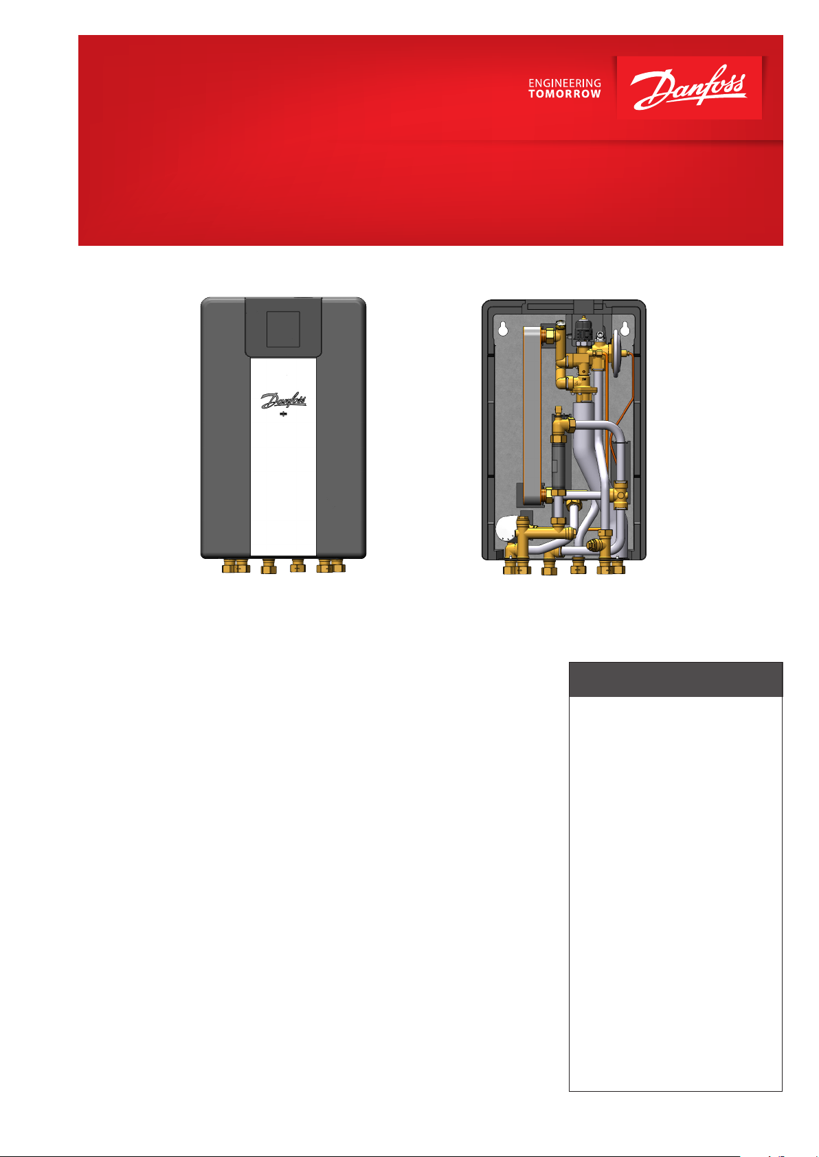
EvoFlat Shaft
Substation for single-family, semi-detached and terraced houses as well as flats.
Substation for direct heating and instantaneous domestic hot water. Innovative
self-acting TPC-M controller for control of
heating and DHW temperature. Designed for
wall-mounting.
Application
The EvoFlat Shaft is a compact and simple to operate substation. The EvoFlat Shaft is especially
suitable for two-pipe systems in residential
buildings, which are supplied from a secondary
connected district heating system, a block heating system or a centrally located boiler system.
The EvoFlat Shaft is available as mount-on-wall
flat station.
Primary side (HS)
The substation is prefabricated with interconnecting components such as a differential pressure controller (integrated in main temperature
controller TPC -M ), strainer, sensor pockets and
fitting piece for insertion of a heat meter. Thermostatic bypass is available as an option.
Heating (HE)
The self-acting temperature controller TPC-M
with integrated differential pressure controller sets the optimum operating conditions for
heating and DHW. In order to enable a time dependent temperature control program, a zone
valve with actuator and a room thermostat can
be included as an option.
Domestic hot water (DHW)
The domestic hot water is prepared in the heat
exchanger based on the flow principle and
the temperature is regulated by the self-acting
controller with integrated differential pressure
controller - the TPC-M. Supreme ease of operation is obtained via the combined hydraulic and
thermostatic regulation of the TPC - M controller. The flow - controlled part allows primary and
secondary side flow through the heat exchanger, oShafty when hot water is tapped and blocks
the flow immediately after completion of the
tapping process. The thermostatic part controls
the domestic hot water temperature. Thanks to
the quick-acting hydraulic control of the heat
exchanger, it is largely protected from the formation of lime scale and growth of bacteria. The
TPC-M controller with integrated differential
pressure controller compensates for variations
in supply temperature and varying differential
pressure and thereby ensures a constant domestic hot water temperature at all times.
Co nstruction
All pipes are made of staiShaftess steel. The connections are made by a newly designed click
connection, which does not need retightening.
Insulation
The EvoFlat Shaft is built up on an EPP insulation back plate and a front insulation cabinet is
available as an option, enabling the customer to
have a fully insulated substation, thus ensuring
reduced heat losses and excellent operating
economy.
FEATURES AND BENEFITS
• Substation for decentralized heating
systems
• Direct heating, DHW heating based
on flow principle with thermostatic
temperature controller
• Innovative, energy-saving controller
TCP - M in combination with high
performance heat exchanger for ondemand water heating without noload losses
• Capacity range CW3, 4, 5 and 6.
• Minimum space required for
installation
• Wall-mounted station
• Pipes and plate heat exchanger
made of stailess steel
• Minimized risk of lime scale and
bacteria formation
• Double-walled, cupper brazed
plate heat exchanger
www.danfoss.com
Page 2
SHALTPLAN - BEISPIEL
538
240
340
1
2
3
4
5
6
7
8
9
10
11
12
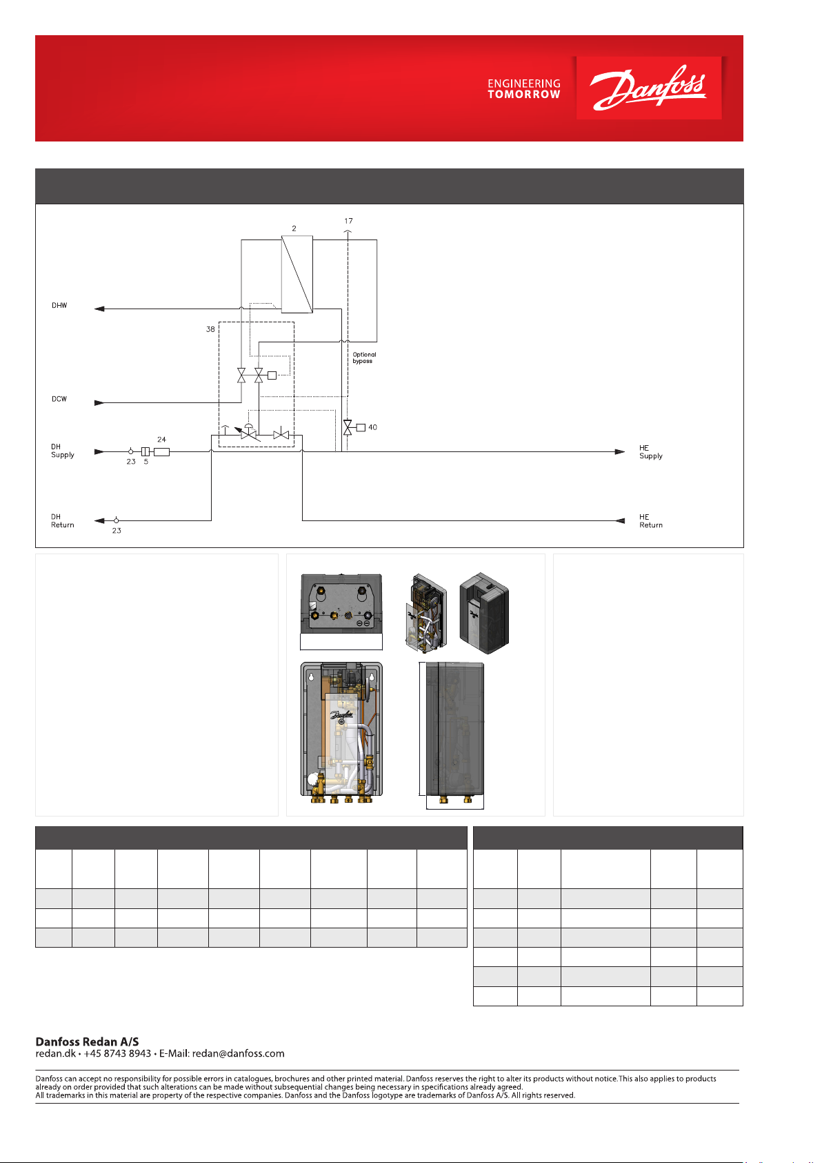
CIRCUIT DIAGRAM - EXAMPLE
2 Plate heat exchanger Danfoss
5 Strainer
23 Sensor pocket
24 Fitting piece for energy meter 3/4” x 110 mm
38 TPC-M hot water controller
40 By-pass
Design specifications:
Nominal pressure (prim/sec.): PN 10/10
Max. supply temperature: 95 °C
Min. supply temperature: 65 °C
DCW static pressure: p
Brazing material (HEX): Copper
Weight : 29 kg
Insulation: EPP λ 0.039
Dimensions (mm): H 538 × W 340 × T 240
Connections sizes:
DH, DCW, DHW, HE: G ¾“ (IT)
DHW: Capacity examples
DHW
Typ e
CW4
CW5
CW6
* w/o heat meter
capacity
KW
27. 0
31.3
42.0
Tem p.
primary
[°C]
65/32. 3 10/60
65/32. 2 10/60
65 /27.0 10/60
Tem p.
secondary
= 1,5 bar
min
[°C]
Dimensional sketch:
1 2
6
3 4 5
Flow rate
primary
[l/h]
Flow rate
secondary
[l/h]
Pressure loss
*primary
[kPa]
Flow rate
primary
[l/min]
710 460 21 12 8
820 540 26 14 9
950 750 29 16 13
Flow rate
secondary
[l/min]
Connections:
1. District heating (DH) supply
2. District heating (DH) return
3. Domestic hot water (DHW)
4. Heating (HE) supply
5. Heating (HE) return
6. Domestic cold water (DCW)
Options:
• Room thermostat
• Actuator for zone valve
• Safety valve
• Ball valves (60 mm)
• Ball valves with connection for pressure
gauge ¾“ (120 mm) incl. safety valve
Heating: Capacity examples
Heating
Capacity
Heating
circuit Δt
kW
10 20 27 430 7
10 30 25 287 5
10 40 24 215 4
15 20 31 645 11
15 30 27 430 7
15 40 25 323 5
* w/o heat meter
Total pressure loss
*primary (at 27 kW DHW)
[° C]
[kPa]
Flow rate
primary
[l/h]
Flow rate
primary
[l/min]
© Danfoss | Produced by Danfoss Redan | 2020.09
AM354740598208en-000101
 Loading...