

Montage- und Betriebsanleitung / Mounting and operating guide
EvoFlat Reno Wohnungsstation mit integriertem Frischwassersystem / Flat station for direct
heating and domestic hot water
Für den Austausch von Gasthermen in Wohnungen und Mehrfamilienhäusern. / For replacement of gas boilers in apartment
buildings and multi-family houses.
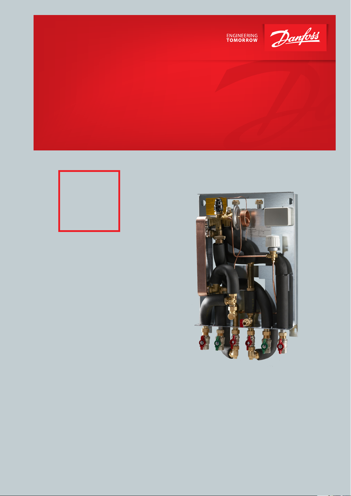
Reno
Für den Austausch
von Gasthermen / For
replacement of gas
boilers
Montage- und Betriebsanleitung / Mounting and Operating guide EvoFlat Reno
EvoFlat Reno mit Rohrleitung nach unten (Standard)
EvoFlat Reno with piping downwards (Standard)
EvoFlat Reno mit Rohrleitung nach oben
EvoFlat Reno with piping upwards
1. INHALT / CONTENT
1.0 Inhaltsverzeichnis / Content ..................................................................................................................................................2
2.0 Allgemeine Sicherheitshinweise / Safety notes ...............................................................................................................3
3.0 Montage / Mounting ..............................................................................................................................................................7
4.0 Inbetriebnahme / Start-up ....................................................................................................................................................9
5.0 Elektrische Anschlüsse / Electrical connection ..................................................................................................................9
6.0 Auau & Beschreibung / Main components & Description ....................................................................................... 10
7.0 Schaltplan / Diagram ........................................................................................................................................................... 12
8.0 Massschizze / Dimensional sketch .................................................................................................................................... 13
9.0 Zubehör / Accessories .......................................................................................................................................................... 14
10.0 Regelkomponente / Controls ............................................................................................................................................. 15
11.0 Wartung / Maintenance ...................................................................................................................................................... 18
12.0 Allgemeine Fehlersuche / General trouble shooting .................................................................................................... 19
13.0 Problemlösung PWH-Versorgung / Trouble shooting DHW supply ......................................................................... 19
14.0 Problemlösung Heizung / Trouble shooting HE ............................................................................................................. 20
15.0 EU Gutachten / EU Declaration of Conformity ................................................................................................................ 24
16.0 Inbetriebnahmezertikat / Commissioning certicate ................................................................................................. 25
2 | © Danfoss | Produced by Danfoss Redan A/S | 2020.02
Montage- und Betriebsanleitung / Mounting and Operating guide EvoFlat Reno
2. ALLGEMEINE SICHERHEITSHINWEISE
Die folgende Anleitung bezieht sich auf das Standarddesign der Station.
Vor der Installation und Inbetriebnahme der Station sollte diese Betriebsanleitung aufmerksam durchgelesen werden. Der Hersteller übernimmt
keine Haftung für Schäden oder Defekte, die aus der Missachtung der Betriebsanleitung resultieren. Bitte lesen und befolgen Sie sämtliche Hinweise,
um Unfälle, Verletzungen und Sachschäden zu vermeiden.
Aufbau, Inbetriebnahme und Wartungsarbeiten dürfen nur von qualifizierten und autorisierten Fachleuten durchgeführt werden.
Beachten Sie bitte die Anleitung des Systemherstellers oder Systembetreibers.
Korrosionsschutz
Alle Rohre und Komponenten bestehen aus Edelstahl und Messing.
Der maximale Chlorgehalt des Flussmediums sollte 150 mg/l NICHT übersteigen.
Das Risiko von Korrosionsschäden steigt beträchtlich an, wenn der empfohlene Chlorgehalt überschritten wird.
Energiequelle
Die Wohnungsstation kann an dezentrale Heizsystemen mit unterschiedlichen Energiequellen, wie Fernwärme, zentraler Kessel (Gas, Öl, Biomasse
usw.), Solarenergie, Wärmepumpe oder eine Kombination aus diesen, wenn
es die Betriebsbedingungen erlauben, angeschlossen werden.
Anwendung
Die Fernwärmestation ist ausschließlich für die Erwärmung von Wasser
konzipiert. Sie darf nicht für die Erwärmung von anderen Medien verwendet werden. Die Wohnungsstation muss in einem frostfreien Raum an die
Hausanlage angeschlossen werden, wo die Raumtemperatur nicht über
50 °C steigt und die Luftfeuchtigkeit 80% nicht überschreitet. Die Station
darf weder abgedeckt noch eingemauert werden und der freie Zugang zur
Station muss stets gewährleistet sein.
Materialwahl
Die Materialwahl erfolgt stets gemäß den geltenden örtlichen Vorschriften.
Geräuschpegel
≤ 55 dB
Nur autorisierte Fachkräfte
Aufbau, Inbetriebnahme und Wartungsarbeiten dürfen
nur von qualifizierten und autorisierten Fachleuten
durchgeführt werden.
Bitte beachten Sie Hinweise in dieser Anleitung.
Um Personenschäden und eine Beschädigung des Geräts zu verhindern, muss diese Anleitung genau beachtet
werden
Warnung vor hohem Druck und hohen Temperaturen
Beachten Sie den erlaubten Systemdruck und die Systemtemperatur der Installation.
Die Höchsttemperatur in der Station beträgt 95 °C.
Der maximale Betriebsdruck der Station beträgt 10 bar.
Das Risiko von Personenschäden und beschädigter Einbauteile nimmt beträchtlich zu, wenn die empfohlenen
zulässigen Betriebsparameter überschritten werden. Die
Installation ist stets unter Beachtung der landestypischen
Vorschriften mit Sicherheitsventilen auszustatten.
Warnung vor heißen Oberflächen
Die Station hat heiße Oberflächen, die zu Verbrennungen
der Haut führen können. Seien Sie bitte in der Nähe der
Station sehr vorsichtig.
Bei einem Stromausfall kann es passieren, dass die Motorventile geöffnet bleiben. Die Oberflächen der Station
können sehr heiß werden und dann bei Berührung zu
Hautverbrennungen führen. Die Kugelhähne an Versorgungsvor- und -rücklauf sollten geschlossen werden.
Anschlussart
Die Station muss mit Vorrichtungen versehen sein, die sicherstellen, dass
die Station von sämtlichen Energiequellen einschließlich der Spannungsversorgung getrennt werden kann.
Notfälle
Bei Gefahr oder Unfällen (wie z. B. durch Feuer, Lecks oder sonstige gefährliche Umstände) sollten – sofern möglich – sämtliche Energiequellen von
der Station getrennt werden. Außerdem sollten Fachleute hinzugezogen
werden.
Bei verfärbtem oder bei übel riechendem Trinkwarmwasser sollten sämtliche Absperrventile an der Station geschlossen werden.
Informieren Sie zudem den zuständigen Versorgungsbetrieb und ziehen
Sie unverzüglich Fachleute hinzu.
Lagerung und Handhabung
Muss die Station vor der Installation gelagert werden, so hat dies unter
trockenen und beheizten Bedingungen zu erfolgen. (Relative Luftfeuchtig
keit max. 80 % und Lagertemperatur 5–70 °C).
Die Fernwärmestationen dürfen nicht höher als im Werk gestapelt werden.
Fernwärmestationen, die in Kartons geliefert werden, müssen an den Handgriffen der Verpackung angehoben werden. Zum Transportieren/Befördern
über große Entfernungen müssen die Fernwärmestationen auf Paletten
platziert werden.
Heben Sie die Fernwärmestation nach Möglichkeit nicht an den Rohren
an, da dadurch Leckagen entstehen können.
Niemals die Station an ihrer Frontabdeckung anheben!
ZIEHEN Sie die Anschlüsse nach dem Transport erneut FEST.
Handhabung
Wir empfehlen, beim Handhaben und Einbauen der
Wohnungsstation geeignetes und sicheres Schuhwerk
zu tragen.
Warnung vor Transportschäden
Stellen Sie bitte vor der Installation der Station sicher, dass
die Station beim Transport nicht beschädigt wurde.
WICHTIGER HINWEIS: Anschlüsse nachziehen
-
Wegen der Erschütterungen während des Transports
müssen alle Flanschanschlüsse und Schraubverbindungen sowie sämtliche elektrischen Klemm- und
Schraubanschlüsse überprüft und ggf. nachgezogen
werden, bevor die Anlage mit Wasser befüllt wird.
Nachdem die Anlage mit Wasser befüllt und in Betrieb
genommen wurde, ist ein erneutes Nachziehen ALLER
Verschraubungen erforderlich. Überprüfen Sie, dass alle
Stifte der Click-Anschlüsse vollständig eingesteckt sind.
Die Installation ist stets unter Beachtung der landestypischen Vorschriften mit Sicherheitsventilen auszustatten.
© Danfoss | Produced by Danfoss Redan A/S | 2020.02 | 3AN33376446555601-000101 145X2025
Montage- und Betriebsanleitung / Mounting and Operating guide EvoFlat Reno
Reach
Sämtliche Produkte der EvoFlat Reno Serie erfüllen die Bestimmungen der
REACH-Verordnung.
Wir sind dem gemäß verpflichtet unsere Kunden über das Vorhandensein von
Stoffen laut SVHC Kandidatenliste zu informieren so diese vorhanden sind.
Hiermit informieren wir Sie: Dieses Produkt enthält Messingteile die Blei
(CAS 7439-92-1) in einer Konzentration über 0,1% Massenprozent enthalten.
Potentialausgleich / Erdung
Unter Potentialausgleich versteht man alle Maßnahmen zum Beseitigen
elektrischer Potentialunterschiede (Kontaktspannungen),
die zwischen z.B zwei Rohrleitungen auftreten können. Der Potentialausgleich ist eine wichtige Maßnahme zum Schutz gegen elektrischen Schlag.
Potentialausgleich reduziert Korrosion im Wärmetauscher, Durchlauferhitzer,
Fernwärmestationen und Sanitärinstallationen. Gemäß DIN VDE 0100-410
ist ein Potentialausgleich nach DIN VDE 0100-540 vorgeschrieben, der alle
vorhandenen metallenen Systeme des Gebäudes sowie die Schutzleiter,
Schutz-, Funktions- und Potentialausgleichsleiter sowie den Erdungsleiter der
elektrischen Anlage über die Haupterdungs-schiene miteinander verbindet.
Entsorgung
Die Station besteht aus Materialien, die nicht zusammen mit dem Hausmüll
entsorgt werden dürfen. Bitte zerlegen Sie das Produkt zur entsorgung in
Einzelteile und führen Sie sie gemäß den geltenden örtlichen Vorschriften
sortenrein der Entsorgung zu.
Bitte bemerken
Eingriffe und Nacharbeiten an unseren
Komponenten führen zum Verlust der Gewährleistung.
4 | © Danfoss | Produced by Danfoss Redan A/S | 2020.02
Montage- und Betriebsanleitung / Mounting and Operating guide EvoFlat Reno
2. SAFETY NOTES
The following instructions refer to the standard design of the station.
This operating manual should be read carefully before installation and startup of the flat station. The manufacturer accepts no liability for damage or
faults that result from non-compliance with the operating manual. Please
read and follow all the instructions carefully to prevent accidents, injury and
damage to property.
Assembly, start-up and maintenance work must be performed by qualified
and authorized personnel only.
Please comply with the instructions issued by the system manufacturer or
system operator.
Corrosion protection
All pipes and components are made of stainless steel and brass.
The maximum chloride compounds of the flow medium should not be higher
than 150 mg/l.
The risk of equipment corrosion increases considerably if the
recommended level of permissible chloride compounds is exceeded.
Energy source
The substation is designed to be connected to decentralized heating installations with various energy sources, such as district heating, central boiler
(gas, oil, biomass, etc.), solar, heat pump or a combination between them if
the operating conditions allow it.
Application
The substation is designed only to operate with water and other heating
media may not be used. The substation is to be connected to the household
piping in a frost-free room, where the temperature does not exceed 50 °C
and the relative humidity is not higher than 80%. The substation must no
be covered, bricked in or otherwise cut off from access.
Choise of materials
Only use materials that comply with local regulations.
Safety valve(s)
Installation of safety valve(s) must always be in compliance with local regulations.
Authorized personnel only
Assembly, start-up and maintenance work must be performed by qualified and authorized personnel only.
Please observe instructions carefully
To avoid injury to persons and damage to the device, it is
absolutely necessary to read and observe these instructions carefully.
Warning of high pressure and temperature
Be aware of the installation’s permissible system pressure
and temperature.
The maximum temperature of the flow medium in the flat
station is 95 °C. The maximum operating pressure of the
flat station is 10 bar. The risk of persons being injured and
equipment damaged increases considerably if the recommended permissible operating parameters are exceeded.
The flat station installation must be equipped with safety
valves, however, always in accordance with local regulations.
Warning of hot surface
The flat station has got hot surfaces, which can cause skin
burns.
Please be extremely cautious in close proximity to the flat
station. Power failure can result in the motor valves being
stuck in open position. The surfaces of the flat station can get
hot, which can cause skin burns. The ball valves on district
heating supply and return should be closed.
Noise level.
≤ 55 dB.
Connection
It must be possible to cut off all energy sources to the system – including
electrical connections – at all times.
Emergencies
In the event of fire, leaks or other hazards, immediately shut off all sources
of energy to the substation, if possible and call for appropriate assistance.
If the domestic hot water is discoloured or malodorous, shut off all ball
valves on the substation, notify all users and call for professional assistance
immediately.
Storage
Before installation, the units must be stored in a dry, heated (i.e. frost-free)
room.
(Relative humidity max. 80% and storage temperature 5-70 °C).
The units must not be stacked higher than the limit at the factory Units supplied in cardboard packaging must be lifted using the handles incorporated
in the packaging. Units must be placed on pallets for transport/moving across
large distances.
As far as possible, do NOT lift the substation by the pipes. Lifting by the pipes
may cause leaks. REMEMBER to retighten.
Handling
We recommend wearing suitable and safe footwear when
handling and installing the district heating station.
Warning of transport damage
Before flat station installation, please make sure that the
flat station has not been damaged during transport.
IMPORTANT - Tightening of connections
Due to vibrations during transport all flange connections,
screw joints and electrical clamp and screw connections
must be checked and tightened before water is added to
the system.
After water has been added to the system and the system
has been put into operation, re-tighten ALL connections.
Check that all hairpins in click connectionsare completely
pushed in.
The installation must always be equipped with safety
valves in accordance with current regulations and local
standards.
© Danfoss | Produced by Danfoss Redan A/S | 2020.02 | 5AN33376446555601-000101 145X2025

Montage- und Betriebsanleitung / Mounting and Operating guide EvoFlat Reno
Reach
All products of the EvoFlat series comply with the provisions of the REACH
regulation.
We are therefore obliged to inform our customers about the presence of
substances according to the SVHC candidate list, if they are present. We
hereby inform you: This product contains brass parts containing lead (CAS
7439-92-1) in a concentration above 1% (w/w).
Potential equalization / grounding
Equipotential bonding is understood as all measures for eliminating electrical potential differences (contact voltages), which can occur between eg
two pipelines. Equipotential bonding is an important measure for protection against electric shock. Equipotential bonding reduces corrosion in the
heat exchanger, instantaneous water heaters, district heating stations and
plumbing installations. Equipotential bonding should be in accordance with
the provisions 60364-4-41: 2007 and IEC 60364-5-54: 2011.
Binding point is marked with a grounding symbol on the bottom right corner
of the mounting plate and there is a hole in the mounting plate and a label
with grounding symbol.
Disposal
The station consists of materials that must not be disposed of with household waste. Disconnect the entire energy supply and disassemble the product for disassembly and dispose of it in accordance with local regulations.
Please notice
Interventions and reworking of our components lead to
the loss of warranty.
6 | © Danfoss | Produced by Danfoss Redan A/S | 2020.02
Montage- und Betriebsanleitung / Mounting and Operating guide EvoFlat Reno
3. MONTAGE
Die Installation muss den lokalen Normen und Richtlinien und dem neusten
Stand der Technik entsprechen.
Wärmequelle: In den folgenden Abschnitten bezeichnet WQ die Wärmequelle, die die Unterstationen versorgt. Eine Vielzahl von Energiequellen,
wie z. B. Öl, Gas oder Solarenergie,kann als Hauptenergiequelle für Unterstationen von Danfoss verwendet werden. Zur Vereinfachung bezeichnet
WQ die Hauptenergiequelle.
Montage:
Ausreichende Abstände
Lassen Sie um die Station herum ausreichende Abstände für Installationsund Wartungsarbeiten.
Ausrichtung:
Die Station muss so montiert werden, dass alle Bauteile, Schlüssellochungen
und Typenschilder ordnungsgemäß positioniert sind. Falls Sie die Station
auf andere Weise montieren möchten, wenden Sie sich an Ihren Händler.
Nur autorisierte Fachkräfte
Aufbau, Inbetriebnahme und Wartungsarbeiten dürfen nur von qualifizierten und autorisierten Fachleuten durchgeführt werden.
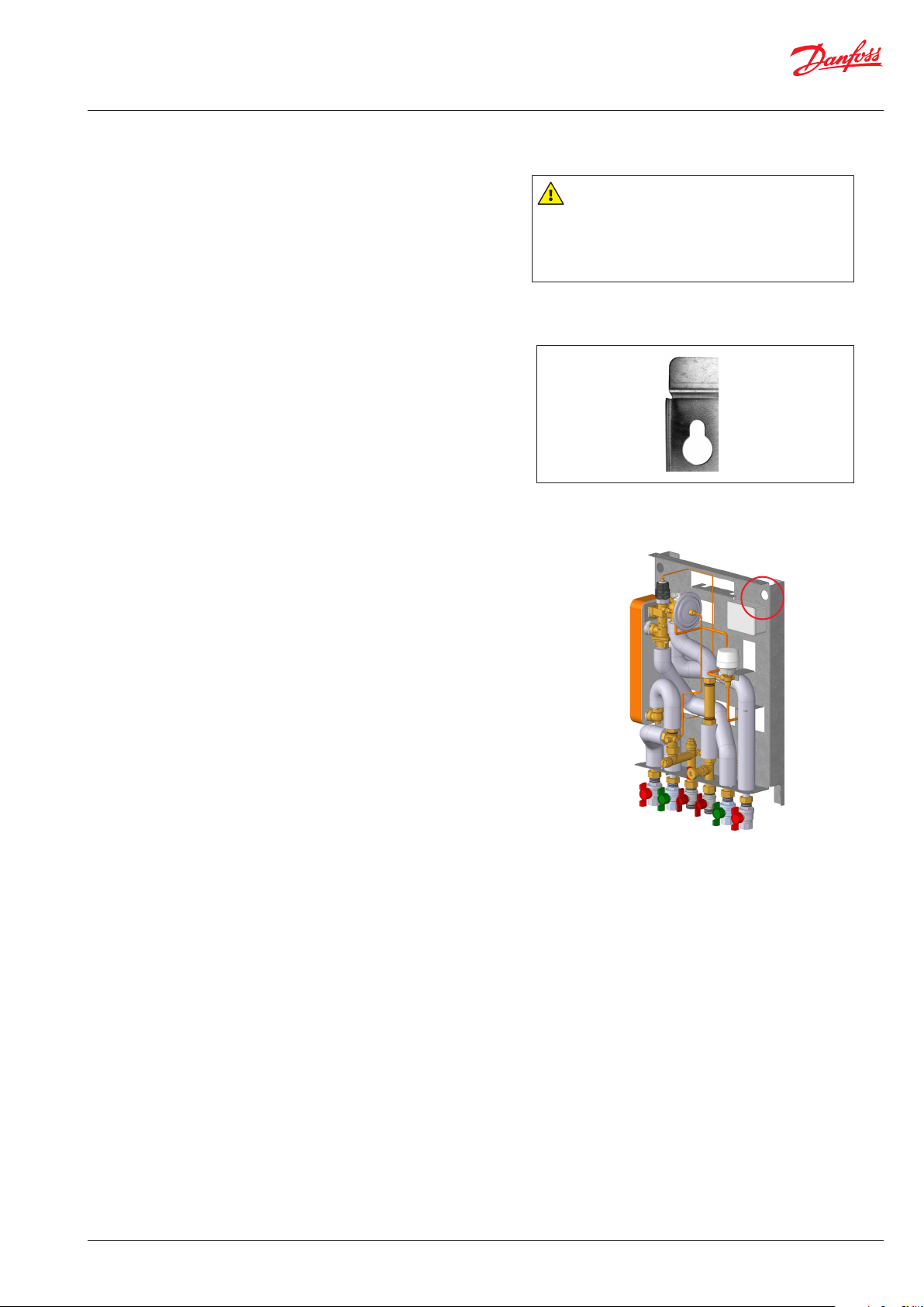
Bohrlöcher:
Zum Anbringen der Station an dieWand befinden sich Bohrlöcher an der
Rückseite der Grundplatte.
Beschriftung:
Jeder Anschluss der Station ist beschriftet.
Vor dem Einbau:
Reinigen und spülen
Vor der Installation sollten alle Rohre und Anschlüsse der Station gereinigt
und gespült werden.
Nachziehen:
Aufgrund von Erschütterungen während des Transports müssen alle Anschlüsse der Station vor der Installation kontrolliert und nachgezogen
werden. Überprüfen Sie, dass alle Stifte der Click-Anschlüsse vollständig
eingesteckt sind.
Nicht verwendete Anschlüsse:
Nicht verwendete Anschlüsse und Absperrventile müssen mit einem Stopfen verschlossen werden. Müssen die Stopfen entfernt werden, darf dies
nur durch einen autorisierten Servicetechniker geschehen.
Einbau:
Schmutzfänger
Im Lieferumfang der Station ist ein Schmutzfänger enthalten. Dieser muss
gemäß der schematischen Darstellung eingebaut und regelmäßig gereinigt
werden.
Bohrloch für die Wandmontage.
Anschlüsse:
Die Anschlüsse an die Hausinstallation und die Versorgungsleitungen sind
mit Gewinde auszuführen.
Die internen Anschlüsse der Wohnungsstation sind Click-Fit-Anschlüsse
(siehe Punkt 10).
© Danfoss | Produced by Danfoss Redan A/S | 2020.02 | 7AN33376446555601-000101 145X2025
Montage- und Betriebsanleitung / Mounting and Operating guide EvoFlat Reno
3. MOUNTING
Installation must be in compliance with local standards and regulations.
Heat Source (HS) - In the following sections, HS refers to the heat source
which supplies the flat stations. A variety of energy sources, such as oil, gas
or solar power, could be used as the primary supply to Danfoss substations.
For the sake of simplicity, HS can be taken to mean the primary supply.
Mounting:
Adequate space
Please allow adequate space around the flat station for mounting and
maintenance purposes.
Orientation
The station must be mounted so that components, keyholes and labels
are placed correctly. If you wish to mount the station differently please
contact your supplier.
Drillings
Where substations are to be wall-mounted, drillings are provided in the
back mounting plate.
Labelling
Each connection on the substation is labelled.
Authorized personnel only
Assembly, start-up and maintenance work must be
performed by qualified and authorized personnel
only.
Keyhole for mounting.
Before installation:
Clean and rinse
Prior to installation, all substation pipes and connections should be cleaned
and rinsed.
Thightening
Due to vibration during transport, all substation connections must be
checked and tightened before installation. Check that all hairpins in click
connections are completely pushed in.
Unused connections
Unused connections and shut-off valves must be sealed with a plug.
Should the plugs require removal, this must only be done by an authorized
service technician.
Installation:
Strainer
If a strainer is supplied with the station it must be fitted according to schematic diagram. Please note that the strainer may be supplied loose.
Connections
Connection to the household installation and district heating pipes
connections must be made using threaded, flanged or welded connections.
The internal connections of the flat station is made by click-fit connections.
(See item 10).
8 | © Danfoss | Produced by Danfoss Redan A/S | 2020.02
145X2025 AN33376446555601-000101
Montage- und Betriebsanleitung / Mounting and Operating guide EvoFlat Reno
4. INBETRIEBNAHME / START-UP
Inbetriebnahme, direktes Heizen
Während der Inbetriebnahme müssen die Absperrventile geöffnet sein
und das Gerät überwacht werden. Prüfen Sie die Temperaturen, Drücke,
thermische Ausdehnung und die Dichtigkeit. Sobald der Wärmeübertrager
ordnungsgemäß arbeitet, kann das Gerät seinen bestimmungsgemäßen
Betrieb aufnehmen.
Nachdem die Anlage mit Wasser befüllt und in Betrieb genommen wurde,
ist ein erneutes Nachziehen ALLER Verschraubungen erforderlich. Überprüfen Sie, dass alle Stifte der Click-Anschlüsse vollständig eingesteckt sind.
Anschlüsse erneut festziehen.
Start-up, Direct heating
The shut-off valves should be opened and the unit observed as it enters
service. Visual checking should confirm temperatures, pressures, acceptable
thermal expansion and absence of leakage.
If the heat exchanger operates in accordance with design, it can be put
to regular use.
After water has been added to the system and the system has been put
into operation, re-tighten ALL connections. Check that all hairpins in click
connections are completely pushed in.
Anschlüsse erneut festziehen
Nachdem die Anlage mit Wasser befüllt und in Betrieb
genommen wurde, ist ein erneutes Nachziehen
ALLER Verschraubungen erforderlich. Überprüfen
Sie, dass alle Stifte der Click-Anschlüsse vollständig
eingesteckt sind.
Re-thighten connections
After water has been added to the system and the system has been put into operation, re-tighten ALL connections. Check that all hairpins in click connections
are completely pushed in.
5. ELEKTRISCHE ANSCHLÜSSE / ELECTRICAL CONNECTION
Vor dem Herstellen der elektrischen Anschlüsse ist folgendes zu
beachten:
Autorisierter Elektriker
Sicherheitshinweise
Lesen Sie hierzu die entsprechenden Sicherheitshinweise.
Elektrischer Anschluss
Die Station muss an einen 230 V AC-Anschluss und an einem Potentialausgleich angeschlossen werden.
Bemerken Sie bitte, dass die EvoFlat Reno in 12 Varianten erhältlich sind,
von welchen 6 Varianten mit einem Konverter für 24 V Ausgangspannung
versehen sind (Siehe Seite 11 für Bestell-Nr.).
Trennung
Der elektrische Anschluss der Station muss so erfolgen, dass sie für Repara
turen vom Strom getrennt werden kann.
Erdung / mögliche Kompensation
Der Potentialausgleich muss auf der rechten Seite der Station an der dafür
vorgesehenen Stelle erfolgen.
Before making electrical connections, please note the following:
Safety notes
Please read the relevant parts of the safety notes.
230 V
The flat station must be connected to 230 V AC and earth.
-
Elektrische Anschlüsse dürfen nur durch einen autorisierten Elektriker hergestellt werden.
Landestypische Vorschriften
Elektrische Anschlüsse müssen nach den aktuellen
Richtlienien und landestypischen Vorschriften erfolgen.
Authorized electrician
Electrical connections must be made by an authorized
electrician only.
Local standards
Electrical connections must be made in accordance
with current regulations and local standards.
Please note that the EvoFlat Reno is available in 12 versions, 6 of which are
equipped with a converter for 24 V output voltage (see page 11 for Code No.).
Disconnection
The substation must be electrically connected so that it can be disconnected for repairs.
Grounding / potential compensation
The station should be connected to a grounding point on the right side of
the station mounting rail.
© Danfoss | Produced by Danfoss Redan A/S | 2020.02 | 9AN33376446555601-000101 145X2025

Montage- und Betriebsanleitung / Mounting and Operating guide EvoFlat Reno
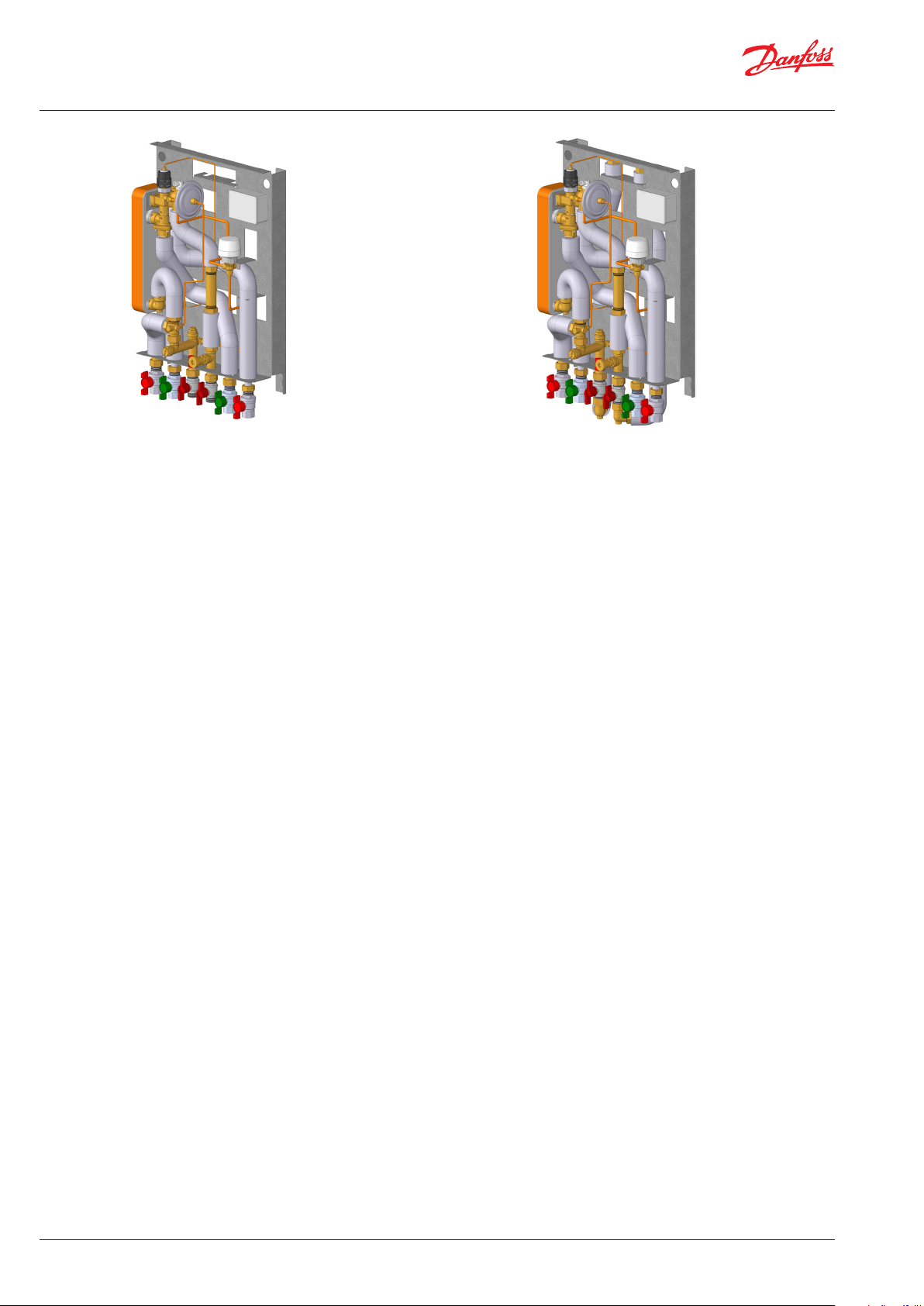
6. AUFBAU / MAIN COMPONENTS
17
38
40
2
24
28
23
19
5
7
Ihre Fernwärmestation kann optisch von der hier abgebildeten Station abweichen / Your flat st ation may look different than the substation shown
2. Plattenwärmetauscherv PWH / Plate heat exchanger DHW
5. Schmutzfänger / Strainer
7. Kugelhahn 3/4” / Ball valve 3/4”
17. Entlüftung / Air vent
19. Entleerventil mit Schlauchtülle / Drain valve with hose nozzle
23. Fühlertasche für WMZ / Sensor pocket for heat meter
24. Passstück für WMZ: 3/4” x 110 mm / Fitting piece for heat meter : 3/4” x 110 mm
28. PWH-Fühler für TPC-M / DHW sensor for TPC-M
38 Warmwasserthermostat / Differenzdruckregler TPC-M / DHW hermostat / Differential pressure controller TPC-M
40. Sommer Bypass / Summer bypass
Beschreibung der Station
Diese Anweisungen gelten für EvoFlat Reno, die eine Wohnungsstation für die Heizung und Trinkwassererwärmung in 2-Rohr-Systemen, die
speziell für den Austausch von Gasthermen in Wohnungen, Einfamilien-, Zweifamilien- und Reihenhäuser entwickelt wurden, ist.
Die EvoFlat Reno enthält einen mehrzweckregler TPC-M mit integriertem Zonenventil, Entlüfter, Differenzdruck- und PWH-Temperaturregler
Differenzdruckregler
Der Differenzdruckregler gleicht die hohen Druckschwankungen, die aus dem Netz kommen, aus und stellt einen konstanten
Betriebsdruck sicher. Dieser konstante Differenzdruck sorgt für eine optimale Funktion der Thermostatventile an den Heizkörpern.
Die EvoFlat Reno Wohnungsstationen sind für Wandmontage konzipiert. Während die vorhandenen Anschlüsse für Warm- und Kaltwasser sowie
Vor- und Rücklauf der Sekundär-Heizkreise ohne große Veränderungen weiter verwendet werden können, empfiehlt es sich die Anschlüsse für
den primärseitigen Heizwasservorlauf und -rücklauf durch den Kamin zu führen.
Die Station ist mit einem Symbol für die verschiedenen Anschlüsse ausgerüstet. Die Station laut diesen und/oder laut der Hinweise dieser
Anleitung an die Hausinstallation anschliessen.
Description of the flat station
The EvoFlat Reno is a flat station for direct heating and a pressure and temperature controlled instantaneous domestic hot water heater for twopipe systems, designed for decentralized heat distribution and is especially suitable for apartment buildings, where existing gas boilers should
be replaced.
The EvoFlat Reno contains a multi-purpose controller TPC-M with integrated zone valve, air vent, differential pressure and PWH temperature
controller.
Differential pressure controller
The differential pressure controller equalizes the high fluctuations in pressure arriving from the heat source, ensuring constant operating pressure. This constant differential pressure ensures that the thermostatic valves on the radiators work optimally.
The EvoFlat Reno Flat Station is prepared for wall-mounting. The existing connections for DHW and DCW as well as supply and return of secondary heating circuits can be used without major changes, but it is recommended that the connections for the primary hot water flow and return
are to lead through the chimney.
The station is equipped with a symbol for the different connections. Connect the station to the house installation according to these and / or
according to the instructions in this instruction manual.
10 | © Danfoss | Produced by Danfoss Redan A/S | 2020.02
145X2025 AN33376446555601-000101

Montage- und Betriebsanleitung / Mounting and Operating guide EvoFlat Reno
6. AUFBAU / MAIN COMPONENTS
Die EvoFlat Reno sind in 12 Varianten erhältlich
Typ Bestell-Nr.
EvoFlat Reno Typ 1 230V, m/XB06H-1 26HP-E * 145B4102
EvoFlat Reno Typ 1 230V, m/XB06H-1 40HP-E * 145B4103
EvoFlat Reno Typ 1 230V, m/XB06H+1 60HP-E * 145B4104
EvoFlat Reno Typ 1 230V, m/XB06H-1-26_2StS_16_A_G3/4 EvoF I-P 72pcs ** 145B4105
EvoFlat Reno Typ 1 230V, m/XB06H-1-40_2StS_16_A_G3/4 EvoF I-P 84pcs ** 145B4106
EvoFlat Reno Typ 1 230V, m/XB06H-1-56_2StS_16_A_X3/4 (EvoF) ** 145B4107
EvoFlat Reno Typ 1 24V, m/XB06H-1 26HP-E *** 145B4108
EvoFlat Reno Typ 1 24V, m/XB06H-1 40HP-E *** 145B4109
EvoFlat Reno Typ 1 24V, m/XB06H+1 60HP-E *** 145B4110
EvoFlat Reno Typ 1 24V, m/XB06H-1-26_2StS_16_A_G3/4 EvoF I-P 72pcs **** 145B4111
EvoFlat Reno Typ 1 24V, m/XB06H-1-40_2StS_16_A_G3/4 EvoF I-P 84pcs **** 145B4112
EvoFlat Reno Typ 1 24V, m/XB06H-1-56_2StS_16_A_X3/4 (EvoF) **** 145B4113
*) Kupfer aufgelöteter HEX, 230 V Anschluss
**) Edelstahl aufgelöteter HEX, 230 V Anschluss
***) Kupfer aufgelöteter HEX, 230 V Anschluss, Trafo für 24 V Ausgangspannung
****) Edelstahl aufgelöteter HEX, 230 V Anschluss, Trafo für 24V Ausgangspannung
Type Code No.
EvoFlat Reno Type 1 230V, w/XB06H-1 26HP-E * 145B4102
EvoFlat Reno Type 1 230V, w/XB06H-1 40HP-E * 145B4103
EvoFlat Reno Type 1 230V, w/XB06H+1 60HP-E * 145B4104
EvoFlat Reno Type 1 230V, w/XB06H-1-26_2StS_16_A_G3/4 EvoF I-P 72pcs ** 145B4105
EvoFlat Reno Type 1 230V, w/XB06H-1-40_2StS_16_A_G3/4 EvoF I-P 84pcs ** 145B4106
EvoFlat Reno Type 1 230V, w/XB06H-1-56_2StS_16_A_X3/4 (EvoF) ** 145B4107
EvoFlat Reno Type 1 24V, w/XB06H-1 26HP-E *** 145B4108
EvoFlat Reno Type 1 24V, w/XB06H-1 40HP-E *** 145B4109
EvoFlat Reno Type 1 24V, w/XB06H+1 60HP-E *** 145B4110
EvoFlat Reno Type 1 24V, w/XB06H-1-26_2StS_16_A_G3/4 EvoF I-P 72pcs **** 145B4111
EvoFlat Reno Type 1 24V, w/XB06H-1-40_2StS_16_A_G3/4 EvoF I-P 84pcs **** 145B4112
EvoFlat Reno Type 1 24V, w/XB06H-1-56_2StS_16_A_X3/4 (EvoF) **** 145B4113
*) Copper soldered HEX, 230 V connection
**) Stainless steel soldered HEX, 230 V connection
***) Copper soldered HEX, 230 V connection, Transformer for 24V output voltage
****) Stainless steel soldered HEX, 230 V connection, Transformer for 24V output voltage
© Danfoss | Produced by Danfoss Redan A/S | 2020.02 | 11AN33376446555601-000101 145X2025

Montage- und Betriebsanleitung / Mounting and Operating guide EvoFlat Reno
7. SCHALTPLÄNE, BEISPIELE /DIAGRAMS, EXAMPLES
2. Plattenwärmetauscher PWH / Plate heat exchanger DHW
5. Schmutzfänger / Strainer
7. Kugelhahn 3/4” / Ball valve 3/4”
17. Entlüftung / Air valve
19. Entleerventil mit Schlauchtülle / Drain valve with hose nozzle
23. Fühlertasche ½” für WMZ / Sensor picket ½” for heat meter
24. Passstück für WMZ: 3/4” x 110 mm / Fitting piece for heat meter
28. Tauchfühler für TPC-M / Immersion sensor for TPC-M
PWH/
DHW
PWC/
DCW
38 Warmwasserthermostat / Differenzdruckregler TPC-M /
DHW thermostat / Differential pressure controller TPC-M
40. Sommer Bypass / Summer bypass
** Anschluss 3/4” (IG) / Connections 3/4” (IT)
FW
Vorlauf/
DH
Supply
FW
Rücklauf/
DH
return
Variant mit Bypass-Funktion nach Wärmenmengenzähler.
Mit Zonenventil einschl. TWA
Variant with Bypass function after heat meter.
With zone valve incl. TWA
PWH/
DHW
HE
Vorlauf/
Supply
HE
Rücklauf/
Return
2. Plattenwärmetauscher PWH / Plate heat exchanger DHW
5. Schmutzfänger / Strainer
7. Kugelhahn 3/4” / Ball valve 3/4”
17. Entlüftung / Air valve
19. Entleerventil mit Schlauchtülle / Drain valve with hose nozzle
23. Fühlertasche ½” für WMZ / Sensor picket ½” for heat meter
24. Passstück für WMZ: 3/4” x 110 mm / Fitting piece for heat meter
28. Tauchfühler für TPC-M / Immersion sensor for TPC-M
38 Warmwasserthermostat / Differenzdruckregler TPC-M /
DHW thermostat / Differential pressure controller TPC-M
40. Sommer Bypass / Summer bypass
52. TWA Stellantrieb / TWA actuator
** Anschluss 3/4” (IG) / Connections 3/4” (IT)
PWC/
DCW
M
FW
Vorlauf/
DH
Supply
FW
Rücklauf/
DH
return
12 | © Danfoss | Produced by Danfoss Redan A/S | 2020.02
HE
Vorlauf/
Supply
HE
Rücklauf/
Return
145X2025 AN33376446555601-000101

Montage- und Betriebsanleitung / Mounting and Operating guide EvoFlat Reno
Rev.
1
2
3
4
5
6
7
8
9
10
11
12
8. MASSSCHIZZE / DIMENSIONAL SKETCH
674,3
1.
2.
3.
4.
5.
6.
95
Heizk. vorlauf
WW
Primär vorlauf
Primär rücklauf
KW
Heizk. rücklauf
204
General tolerance accuracy, measurements without tolerance:
ISO 2768 - mK
Weight
Replace
Design
11-07-2018
Approval
Confidential: Property of Danfoss Redan A/S, Nordborg, Denmark.
Not to be handed over to, copied or used by third party. Two- or three
dimensional reproduction of contents to be authorized by Danfoss Redan A/S.
39.03 kg
HMS
Projection
Scale
Size
Material
1:2.5
A2
Danfoss Standard
Designation
Danfoss Redan A/S
No.
Evoflat Reno
Sheet
1 / 1
1 2 3 4 5 6
65 65 65 65 65
410
Anschlüsse / Connections:
1. Heizungs-Vorlauf (HVL) / Heating (HE) supply
2. Trinkwarmwasser (PWH) / Domestic hot water (DHW)
3. Primärseite (FW-Vorlauf) / District heating (DH) supply
4. Primärseite (FW-Rücklauf) / District heating (DH) return
5. Kaltwasser (PWC) / Domestic cold water (DCW)
6. Heizungs-Rücklauf (HRL) / Heating (HE) return
© Danfoss | Produced by Danfoss Redan A/S | 2020.02 | 13AN33376446555601-000101 145X2025

Montage- und Betriebsanleitung / Mounting and Operating guide EvoFlat Reno
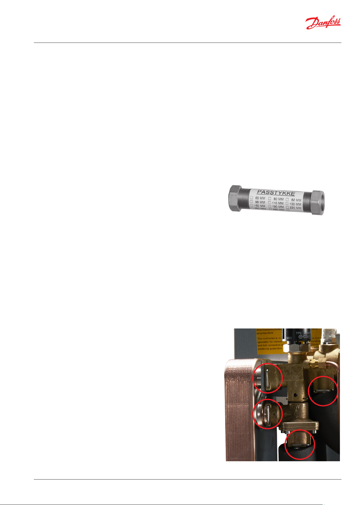
9. ZUBEHÖR / ACCESSORIES
Rohrsatz / Pipe set
Für Anschluss oben / For connection upwards
1
Für die EvoFlat Reno Stationen ist Anschluß oben oder unten möglich.
Bei Lieferung ist die Station für Anschluss nach unten vorbereitet.
Für Anschluß oben ist ein Rohrsatz 145H4920 (Foto 1) als Sonderzubehör erhältlich.
Diese Rohren sind auf den Anschlussrohren unten einzubauen und nach oben zu führen. Siehe Foto 2 + 3.
For the EvoFlat Reno stations, connection at the top or bottom is possible.
On delivery, the station is prepared for connection downwards.
A pipe kit 145H4920 (photo 1) is available as accessory for connection upwards.
These pipes are to be installed on the connection pipes at the bottom and led upwards. See photo 2 + 3.
2 3
Abdeckhaube / Cover
Weiße Abdeckhaube / White cover
1 2 3
Für die EvoFlat Reno Stationen ist eine weiße Abdeckhaube PROTO.854 (Foto 1) als Sonderzubehör erhältlich.
Die Rückplatte der EvoFlat Reno Station und die Abdeckhaube sind für Montage der Abdeckhaube vorbeitet. - Siehe bitte Foto 2 + 3.
Die Zapfen in der Abdeckhaube werden einfach in die Löcher oben in der Rückplatte und in die Aussparung an der Seite der Rückplatte
eingesetzt.
A white cover PROTO.854 (photo 1) is available as accessory for the EvoFlat Reno flat stations.
The back plate of the EvoFlat Reno flat station and the cover are prepared for mounting of the cover. - Please see photo 2 + 3.
The pins in the cover are simply inserted into the holes in the top of the backplate and into the recess on the side of the backplate.
14 | © Danfoss | Produced by Danfoss Redan A/S | 2020.02
145X2025 AN33376446555601-000101

Montage- und Betriebsanleitung / Mounting and Operating guide EvoFlat Reno
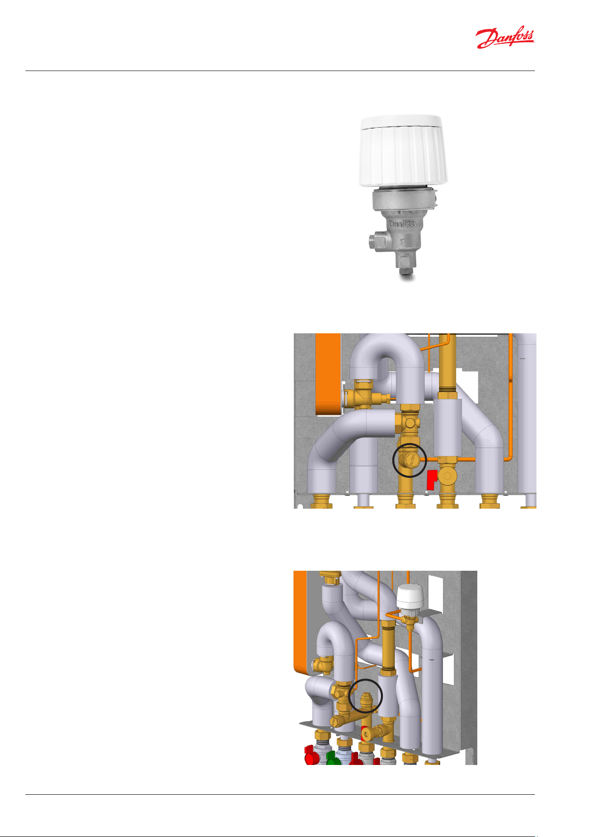
10. REGELKOMPONENTE / CONTROLS
Mehrzweckregler TPC-M
Mehrzweckregler mit integriertem Zonenventil, Entlüfter, Differenzdruck- und
TWW-Temperaturregler.
PWH Temperaturregelung
Durch das Drehen des Handgriffs für die Temperatureinstellung in die Plus-Richtung (+/MAX), erhöht sich die Temperatur. Eine Drehung in die Minus-Richtung
(-/MIN) bewirkt dagegen eine Senkung der Temperatur.
Einstellbereich: 40–60 °C.
Die PWH-Temperatur sollte auf 50 °C eingestellt werden, da somit das Warmwasser optimal genutzt werden kann. Bei PWH-Temperaturen über 55 °C steigt
die Wahrscheinlichkeit von Kalkablagerungen deutlich an.
Differenzdruckregler
Der Differenzdruckregler gleicht die hohen Druckschwankungen, die aus dem
Netz kommen, aus und stellt einen konstanten betriebsdruck sicher.
Zonenventil
Der Mehrzweckregler TPC-M enthält ein Zonenventil.
Der Stellantrieb TWA kann auf dem Zonenventil befestigt werden.
Vor Verwendung des Stellantriebs TWA ist der Transportschutz zu ent-fernen.
Der thermischen Stellantrieb ermöglicht Anschluss an einen elektronischen programmierbaren
Raumthermostat.
Der TWA ist ein thermischer Stellantrieb zum Öffnen und Schliessen von Ventilen. Der thermischer
Stellantrieb wird von dem Raumthermostat über ein Stromkabel geschaltet und öffnet
das Ventil wenn er mit Spannung versorgt wird. Ohne Spannung schliesst der Stellantrieb selbstständig.
Ein gut sichtbarer Positionsgeber zeigt an, ob das Ventil geöffnet oder geschlossen ist.
Entlüftung
Die Station sollte während der Inbetriebnahme entlüftet werden.
TPC-M multi-functional controller
Multi-functional controller with integrated zone valve, air vent, differential pressure and DHW temperature controller.
DHW temperature control
direction the temperature is increased, by turning it in (-/MIN) direction the
temperature is decreased.
Setting range 40-60°C.
DHW temperature should be adjusted to 45-50 °C, as this provides optimal
utilization of DH water. At DHW temperatures above 55 °C the possibility of lime
scale deposits increases significantly.
TPC-M
Termischer Stellantrieb TWA /Thermal actuator
Differential pressure controller
The differential pressure controller equalizes the high fluctuations in pressure
arriving from the heat source, ensuring constant operating pressure.
Zone valve
The TPC-M multi-functional controller contains a zone valve.
The TWA actuator can be mounted on the zone valve.
The transport protection on the TWA actuator must be removed before use.
The thermal actuator TWA enables connection to an electronic programmable room thermo-
stat.
The thermal actuator is switched on by an external contact from the room thermostat, and starts to
open or close the valve. The actuating movement is achieved by means of an electrically heated expansion element. When the heating current is switched off, the actuator shuts or opens the valve.
The actuator is equipped with a visual position indicator to show the open or closed position
of the valve.
Air vent
The station should be vented during start up.
Entlüftung / Air valve
© Danfoss | Produced by Danfoss Redan A/S | 2020.02 | 15AN33376446555601-000101 145X2025
Montage- und Betriebsanleitung / Mounting and Operating guide EvoFlat Reno
10. REGELKOMPONENTE / CONTROLS
Sommer Bypass
Das Bypass-Thermostat hält die Vorlaufleitung warm.
Einstellbereich: 10-50°C.
Skaleneinstellung (indikativ).
Werkseinstellung 2,5.
Summer bypass
The bypass thermostat is designed to keep the supply line warm.
Setting range: 10-50°C.
Scale setting (indicative).
Factory setting 2,5.
Sommer Bypass / Summer bypass
Schmutzfänger
Schmutzfänger sollten regelmäßig von autorisierten Fachkräften
gereinigt werden. Die Häufigkeit der Reinigung ist von den
Betriebsbedingungen abhängig.
Strainer
Strainers should be cleaned regularly by authorized personnel. The
frequency of cleaning would depend on operating conditions.
Tauchhülse, Wärmemengenzähler
Der Fühler des Wärmemengenzählers wird in die Tauchhülsen
eingebaut.
Sensor pocket, energy meter
The sensor of the energy meter is mounted in the sensor pockets.
The sensor pocket is placed in the strainer.
Schmutzfänger / Strainer
16 | © Danfoss | Produced by Danfoss Redan A/S | 2020.02
Tauchhülse / Sensor pocket
145X2025 AN33376446555601-000101
Montage- und Betriebsanleitung / Mounting and Operating guide EvoFlat Reno
10. REGELKOMPONENTE / CONTROLS
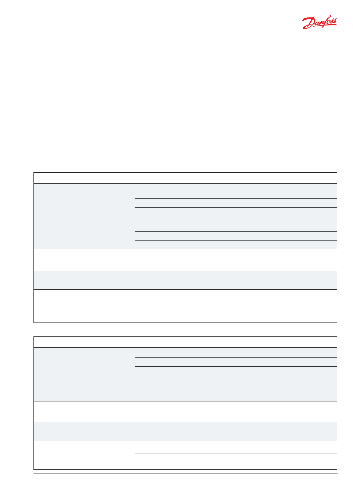
Passstück
Die Übergabestation ist mit einem Passstück für den Wärmemengenzähler ausgestattet.
Einbau von Energiezählern:
1: Kugelhähne schließen
Kugelhähne an FW Vorlauf und FW Rücklauf schließen, falls sich
Wasser in der Anlage befindet.
2: Muttern lösen
Muttern am Passstück lösen.
3: Passstück entfernen
Passstück entfernen und durch Wärmemengenzähler ersetzen.
Dichtungen nicht vergessen.
4: Verbindungen festziehen
Nach dem Einbau des Wärmemengenzähler müssen unbedingt
sämtliche Gewindeanschlüsse überprüft und festgezogen werden.
Fitting piece
The flatstation is equipped with a fitting piece for energy meter.
Mounting of energy meters:
1: Close ball valves
Close the ball valves on DH Supply and DH Return, if there is water on
the system.
2: Loosen nuts
Loosen the nuts on the fitting piece.
3: Remove fitting piece
Remove the fitting piece and replace it with the energy meter. Do ot
forget the gaskets.
4: Tighten connections
After mounting of the energy meter remember to check and tighten all
threaded connections.
Click-Anschluss
Die Klick-Verbindung kann während des Service demontiert
werden.
Passstück / Fitting piece
Click connection
The click connection can be dismantled during service.
Click-Anschluss / Click connection
© Danfoss | Produced by Danfoss Redan A/S | 2020.02 | 17AN33376446555601-000101 145X2025

Montage- und Betriebsanleitung / Mounting and Operating guide EvoFlat Reno
11. WARTUNG / MAINTENANCE
Wartungs- und Überprüfungsarbeiten an der Station gemäß dieser
Anleitung sind regelmäßig durchzuführen und sollten Folgendes
umfassen:
Schmutzfänger
Reinigung der Schmutzfänger.
Wärmemengenzähler
Überprüfung sämtlicher Betriebsparameter – bspw. der abgelesenen Messwerte.
Temperaturen
Überprüfung sämtlicher Temperaturen, z. B. der Temperatur der
Wärmequelle und der Trinkwarmwassertemperatur.
Anschlüsse
Überprüfung sämtlicher Anschlüsse auf Leckagen.
Entlüftung
Überprüfen Sie, ob die Anlage gründlich entlüftet wurde.
Ersatzteile können bei Danfoss bestellt werden. Stellen Sie bitte sicher, dass Sie in Ihrer Anfrage auch die Seriennummer der Station
angeben.
Nur autorisierte Fachkräfte
Aufbau, Inbetriebnahme und Wartungsarbeiten dürfen
nur von qualifizierten und autorisierten Fachleuten
durchgeführt werden.
Maintenance and inspection work at the station in accordance with
these instructions should be carried out regularly and should include the following:
Strainers
Cleaning of strainers.
Meters
Checking of all operating parameters such as meter readings.
Temperatures
Checking of all temperatures, such as HS supply temperature and
DHW temperature.
Connections
Checking all connections for leakages.
Venting
Checking that the system is thoroughly vented.
Spare parts can be ordered from Danfoss. Please ensure that any
enquiry includes the flat station serial number.
Authorized personnel only
Assembly, start-up and maintenance work must be performed by qualified and authorized personnel only.
18 | © Danfoss | Produced by Danfoss Redan A/S | 2020.02
145X2025 AN33376446555601-000101
Montage- und Betriebsanleitung / Mounting and Operating guide EvoFlat Reno
12. ALLGEMEINE FEHLERSUCHE / GENERAL TROUBLESHOOTING
Bei Betriebsstörungen sollten vor dem Ergreifen von Massnahmen folgende grundsätzliche Aspekte überprüft werden:
• Ist die Station an die Spannungsversorgung angeschlossen?
• Ist der Filter der WQ-Vorlaufleitung sauber?
• Ist die Vorlaufleitung sauber?
• Ist der Druckunterschied gleich oder höher als der normale (lokale) Druckunterschied im WQ-Netzwerk? Fragen Sie im Zweifel beim
Betreiber der WQ-Anlage nach.
In the event of operating disturbances, the following basic features should be checked before carrying out actual troubleshooting:
• the flat station is connected to electricity,
• the strainer on the HS supply pipe is clean,
• the HS supply pipe is clean
• the differential pressure is equal to or higher than the normal (local) differential pressure in the HS network – if in doubt, ask
the HS plant supervisor.
13. PROBLEMLÖSUNG PWH-VERSORGUNG / TROUBLESHOOTING DHW SUPPLY
Problem Möglicher Grund Lösung
Zu wenig oder kein Trinkwarmwasser. Schmutzfänger im Vor- oder Rücklauf
verstopft.
Rückschlagventil defekt oder verstopft. Austauschen - reinigen.
Kein Strom Prüfen.
Ablagerungen auf dem Platten-
wärmeübertrager.
Defekte Temperaturmessfühler. Prüfen - austauschen.
Defekter Regler. Prüfen - austauschen.
Warmwasser ist nur an einigen Zapfstellen
verfügbar.
Zapftemperatur zu hoch;
TWW- Zapfleistung zu hoch.
Temperaturabfall bei der Wasserentnahme. Ablagerungen auf dem Platten-
Problem Possible cause Solution
Too little or no DHW. Strainer in supply or return line clogged. Clean strainer(s).
Kaltes und warmes Trinkwasser werden
vermischt, z. B. in einem defekten Thermostatmischventil.
Tehrmostatventil zu hoch eingestellt. Temperaturregler ist defekt.
wärmeübertrager
Stärkerer PWH-durchfluss als für die Fernwärmestation vorgesehen.
Schmutzfänger reinigen.
Austauschen - ausspülen.
Prüfen - austauschen.
Prüfen - einstellen - austauschen.
Austauschen - ausspülen.
PWH - Durchfluss reduzieren/begrenzen.
Defective or clogged non-return valve. Replace – clean.
No electricity. Check.
Scaling of the plate heat exchanger. Replace – rinse out.
Defective temperature sensors. Check – replace.
Defective controller. Check – replace.
Hot water in some taps but not in all. DCW is being mixed with the DHW, e.g. in
a defective thermostatic mixing valve.
Tap temperature too high; DHWH tap load
too high.
Temperature drop during tapping. Scaling of the plate heat exchanger. Replace – rinse out.
Thermostatic valve adjusted to a too high
level. Thermostat is defect.
Larger DHW flow than the flat station has
been designed for.
© Danfoss | Produced by Danfoss Redan A/S | 2020.02 | 19AN33376446555601-000101 145X2025
Check – replace.
Check – set – replace.
Reduce DHW flow.
Montage- und Betriebsanleitung / Mounting and Operating guide EvoFlat Reno
14. PROBLEMLÖSUNG HEIZUNG
Problem Möglicher Grund Lösung
Zu wenig oder zu viel wärme. Scmutzfänger im WQ- oder Heizkreiz
(Heizkörperkreis) ist verstopft.
Der Filter im Wärmemengenzähler des
WQ-Kreises ist verstopft.
Differenzdruckregler defekt Ersetzen Sie den Hauptregler, TPC.
Fühler defekt. Funktion de Thermostats prüfen - bei
Luft in der Anlage Prüfen - austauschen.
Begrenzung der Rücklauftemperatur zu
niedrig eingestellt.
Defekte Heizkörperventile. Prüfen - austauschen.
Scmutzfänger reinigen.
Filter reinigen (nach Rücksprache mit
dem Betreiber der WQ-Anlage).
Bedarf Ventilsitz reinigen.
Ausgleichsventile einstellen/einbauen.
Ungleichmässige Wärmeverteilung im
Gebäude, weil die Ausgleicschventile
vorhanden sind.
Durchmesser der Zulaufleitung zur Leitungsabmessungen prüfen.
Ungleichmässige Wärmeverteilung. Luft in der Anlage. Installation komplett entlüften.
WQ-Vorlauftemperatur zu hoch. Defekter Regler. Der Regler reagiert
nicht so, wie er diesgemäss Anleitung
sollte.
Fühler des selbsttätigen Thermostats
istdefekt.
WQ-Vorlauftemeratur zu niedrig. Defekter Regler. Der Regler reagiert
nichtso, wie er dies gemäss Anleitung
sollte.
Schmutzfänger verstopft. Verschluss/Schmutzfänger reinigen.
Ausgleichsventile einstellen/ einbauen.
Hersteller der automatischen Steuerung
hinzuziehen oder Regler austauschen.
Temperaturregler austauschen.
Hersteller der automatischen Steuerung
hinzuziehen oder Regler austauschen.
20 | © Danfoss | Produced by Danfoss Redan A/S | 2020.02
145X2025 AN33376446555601-000101
Montage- und Betriebsanleitung / Mounting and Operating guide EvoFlat Reno
WQ-Rücklauftemperatur zu hoch. Zu geringe Heizfläche/zu kleine
Gesamtheizfläche erhöhen.
Heizkörper im Vergleich zum Gesamtheizbedarf des Gebäudes.
Schlechte Nutzung der
vorhandenen Heizfläche. Fühler des
selbsttätigen Thermostats ist defekt.
Sicherstellen, dass die Wärme
gleichmässig über die ganze Heiz-
fläche verteilt wird - alle Heizkörper
aufdrehen und verhindern, dass die
Heizkörper im System unten zu heiß
werden. Es ist sehr wichtig, die Tem-
peratur im Vorlauf der Hezkörper so
gering wie möglich zu halten, um
eine angenehme Temperatur zu
erreichen.
Das System ist ein Einrohrsystem. Das System sollte mit elektronis-
chen Reglern und Rücklauffühlern
ausgestattet sein.
Luft im System. System entlüften.
Defekte(s) oder falsch eingestellte(s)
Prüfen - einstellen/austauschen.
Heizkörperventil(e). Einrohrsysteme
erfordern besondere Einrohrheizkörperventile.
Schmutz im Differenzdruckregler. Prüfen - reinigen.
Fühler defekt. Prüfen - austauschen.
System ist zu laut. Heizkörperventile sind zu laut. Durchflussrichtung überprüfen.
Heizlast zu hoch. Fühler defekt. Prüfen - austausschen.
Entsorgung
Dieses Produkt sollte vor dem Recycling oder der
Entsorgung zerlegt und ggf. in unterschiedliche
Materialgruppen sortiert werden.
Beachten Sie stets die örtlichen Entsorgungsbestimmungen.
© Danfoss | Produced by Danfoss Redan A/S | 2020.02 | 21AN33376446555601-000101 145X2025
Montage- und Betriebsanleitung / Mounting and Operating guide EvoFlat Reno
14. TROUBLESHOOTING HE
Problem Possible cause Solution
Too little or no heat. Strainer clogged in HS or HE circuit
(radiator circuit).
The filter in the energy meter on HS
circuit clogged.
Defective differential pressure controller. Replace main controller, TPC.
Sensor defective. Check the operation of the thermostat –
Air pockets in the system. Vent the installation thoroughly.
Limiting of the return temperature
adjusted too low.
Defective radiator valves. Check – replace.
Clean gate/strainer(s).
Clean the filter (after consulting the HS
plant operator).
clean the valve seat if required.
Adjust according to instructions.
Uneven heat distribution in building
because of incorrectly set balancing
valves, or because there are no balancing valves.
Diameter of pipe to flat station too small
or branch pipe too long.
Uneven heat distribution. Air pockets in the system. Vent the installation thoroughly.
HS supply temperature too high. Defective controller. The controller does
not react as it should according to the
instructions.
Defective sensor on self-acting thermostat. Replace thermostat.
HS supply temperature too low. Defective controller. The controller does
not react as it should according to the
instructions.
Strainer clogged. Clean gate/strainer.
Adjust/install balancing valves.
Check pipe dimensions.
Call automatic controls manufacturer or
replace the regulator.
Call in automatic controls manufacturer
or replace controller.
22 | © Danfoss | Produced by Danfoss Redan A/S | 2020.02
145X2025 AN33376446555601-000101
Montage- und Betriebsanleitung / Mounting and Operating guide EvoFlat Reno
Too high HS return temperature. Too small heating surface/too small
Increase total heating surface.
radiators compared to the total
heating requirement of the building.
Poor utilization of existing heating
surface.
Defective sensor on self-acting
thermostat.
Make sure the heat is distributed
evenly across the full heating sur-
face – open all radiators and keep
the radiators in the system from
heating up at the bottom. It is ex-
tremely important to keep the sup-
ply temperature to the radiators as
low as possible, while maintaining a
reasonable level of comfort.
The system is single pipe loop. Das System sollte mit elektronis-
chen Reglern und Rücklauffühlern
ausgestattet sein.
Air in system. System entlüften.
Defective or incorrectly set radiator
Check – set/replace.
valve(s). Single pipe loop systems require special one-pipe radiator valves.
Dirt in the differential pressure
Check – clean out.
controller.
Defective sensor. Check – replace.
Noise in system. Noice from radiator valves. Check flow direction.
Heat load too high. Defective motorized valve, sensor or
electronic controller.
Check – replace.
Disposal
This product should be dismantled and its components
sorted, if possible, in various groups before recycling
or disposal.
Always follow the local disposal regulations.
© Danfoss | Produced by Danfoss Redan A/S | 2020.02 | 23AN33376446555601-000101 145X2025
Montage- und Betriebsanleitung / Mounting and Operating guide EvoFlat Reno
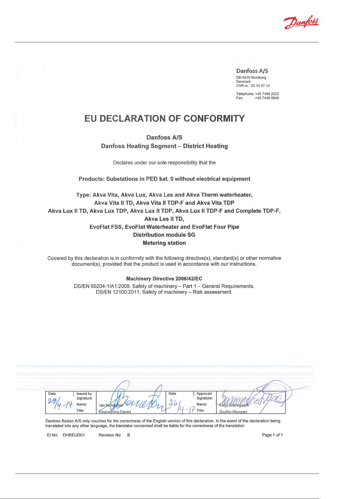
15. EU GUTACHTEN / EU DECLARATION OF CONFORMITY
24 | © Danfoss | Produced by Danfoss Redan A/S | 2020.02
145X2025 AN33376446555601-000101

Montage- und Betriebsanleitung / Mounting and Operating guide EvoFlat Reno
16. INBETRIEBNAHMEZERTIFIKAT / COMMISSIONING CERTIFICATE
Die Station ist die direkte Verbindung zwischen der Fernwärmeversorgung und der Hausinstallation.
Vor der Inbetriebnahme der Wohnungsstation ist die übrige Anlage gründlich zu spülen und die Dichtheit der Verbindungen ist zu überprüfen. Sobald das System mit Wasser gefüllt worden ist, müssen alle Rohrverbindungen, bevor Druckprobe auf Dichtheit, nachgezogen
werden. Die Schmutzfänger reinigen und die Einstellungen gemäss der Hinweise dieser Betriebsanleitung durchführen.
Beim Einbau sind alle örtlichen Standards und Vorschriften einzuhalten.
Installation und erste Inbetriebnahme dürfen nur von qualifizierten und autorisierten Personen durchgeführt werden.
Die Station ist in der Fabrik auf Dichtigkeit vor der Auslieferung geprüft worden, aber nach Transpor t, Handhabung und Aufheizen der Anlage
sind sämtliche Verschraubungen und Anschlusse zu kontrollieren und gegebenenfalls nachzuziehen. Bitte beachten Sie, dass die Verbindungen mit EPDM Gummidichtungen ausgeführt werden können. Deshalb ist es sehr wichtig die Überwurfmutter nicht zu überspannen,
da dies zu Undichtigkeiten führen kann. Der Hersteller übernimmt keine Haftung für Leckagen, die aus Überspannung zurückzuführen sind.
Von dem Installateur auszufüllen
Diese Anlage wurde nachgezogen, angepasst und in Betrieb genommen
den:
Datum/Jahre
Firmenname (Stempel)
The station is the direct link between the district heating supply and the house installation.
Before commissioning the home station, the rest of the system must be thoroughly rinsed and the tightness of the connections checked.
Once the system has been filled with water, all pipe connections must be retightened before pressure testing for leaks. Clean the dirt traps
and adjust according to the instructions in this manual.
When installing, comply with all local standards and regulations.
Installation and commissioning must only be carried out by qualified and authorized persons.
The station has been tested in the factory for leaks before delivery, but after transport, handling and heating of the system, all screw connections and connections must be checked and, if necessary, tightened. Please note that the connections can be made with EPDM rubber
gaskets. Therefore, it is very important not to over-tighten the union nut, as this can lead to leaks. The manufacturer assumes no liability
for leaks resulting from overvoltage.
To be completed by the installer
This plant has been redrawn, adapted and put into operation
date: by installer:
Datum/Jahre
Firmenname (Stempel)
© Danfoss | Produced by Danfoss Redan A/S | 2020.02 | 25AN33376446555601-000101 145X2025

Montage- und Betriebsanleitung / Mounting and Operating guide EvoFlat Reno
26 | © Danfoss | Produced by Danfoss Redan A/S | 2020.02
145X2025 AN33376446555601-000101

Montage- und Betriebsanleitung / Mounting and Operating guide EvoFlat Reno
© Danfoss | Produced by Danfoss Redan A/S | 2020.02 | 27AN33376446555601-000101 145X2025

dk
28 | © Danfoss | Produced by Danfoss Redan A/S | 2020.02 145X2025
AN33376446555601-000101
 Loading...