

Page 1
Mounting and installation instructions
EvoFlat Flat Stations for apartments,
single- and multi-family houses
Complete heat-insulated flat stations for direct heating and instantaneous domestic hot water
EvoFlat
Flat Stations for apartments, single- and
multi-family houses
Page 2
Mounting and installation instructions EvoFlat
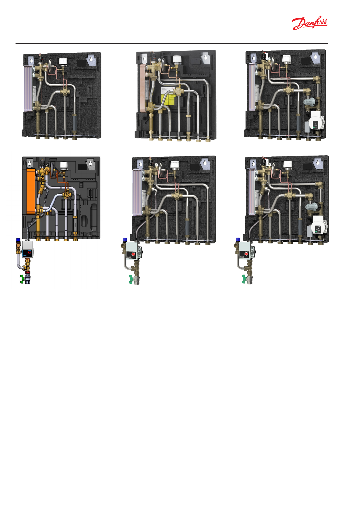
EvoFlat FSS
EvoFlat WSS , with circulation
EvoFlat MSSEvoFlat WSS
EvoFlat MSS, with circulationEvoFlat FSS, with circulation
1. CONTENT
1.0 Table of contents .............................................................................................................................................................................. 2
2.0 Safety notes ...................................................................................................................................................................................... 3
2.1 Safety notes - general ..................................................................................................................................................................................3
3.0 Mounting .......................................................................................................................................................................................... 5
3.1 Mounting .........................................................................................................................................................................................................5
3.2 Start-up............................................................................................................................................................................................................6
3.3 Electrical connections ...................................................................................................................................................................................7
4.0 Construction...................................................................................................................................................................................... 8
4.1 Construction & Dimensional sketches, WSS ............................................................................................................................................8
4.2 Diagrams, WSS ...............................................................................................................................................................................................9
4.3 Construction & Dimensional sketches, FSS Standard ..........................................................................................................................10
4.4 Diagrams, FSS ...............................................................................................................................................................................................11
4.5 Construction & Dimensional sketches, MSS Standard .........................................................................................................................12
4.6 Diagrams, MSS .............................................................................................................................................................................................13
4.7 Construction & Dimensional sketches, FSS & MSS A ...........................................................................................................................14
4.8 Diagrams, FSS & MSS A ..............................................................................................................................................................................15
5.0 Controls ...........................................................................................................................................................................................16
6.0 Maintenance ................................................................................................................................................................................... 21
7.0 Troubleshooting ............................................................................................................................................................................. 22
7.1 General troubleshooting ............................................................................................................................................................................22
7.2 Troubleshooting: DHW ...............................................................................................................................................................................22
7.3 Troubleshooting: HE ....................................................................................................................................................................................23
7.4 Disposal ..........................................................................................................................................................................................................24
8.0 Declaration ...................................................................................................................................................................................... 26
8.1 EU declaration of conformity.....................................................................................................................................................................26
2 | © Danfoss | Produced by Danfoss Redan A/S | 2020.12
AQ15928645880503-020501
Page 3
Mounting and installation instructions EvoFlat
2.0 SAFETY NOTES
2.1 Safety Notes – general
The following instructions refer to the standard design of flat stations.
This operating manual should be read carefully before installation and
start-up of the flat station. The manufacturer accepts no liability for damage or faults that result from non-compliance with the operating manual.
Please read and follow all the instructions carefully to prevent accidents,
injury and damage to property.
Assembly, start-up and maintenance work must be performed by qualified
and authorized personnel only.
Please comply with the instructions issued by the system
manufacturer or system operator.
Corrosion protection
All pipes and components are made of stainless steel and brass.
The maximum chloride compounds of the flow medium should not be
higher than 150 mg/l.
The risk of equipment corrosion increases considerably if the recommended
level of permissible chloride compounds is exceeded.
Energy source
The flat station is designed to be connected to decentralized heating installations with various energy sources, such as district heating, central boiler
(gas, oil, biomass, etc.), solar, heat pump or a combination between them
if the operating conditions allow it.
Application
The flat station is designed to be connected to the house installation in
a frost-free room, where the temperature does not exceed 50 °C and the
humidity does not exceed 80%. Do not cover or wall up the flat station or
in any other way block the entrance to the station.
Authorized personnel only
Assembly, start-up and maintenance work must be performed by qualified and authorized personnel only.
Please observe instructions carefully
To avoid injury to persons and damage to the device, it is
absolutely necessary to read and observe these instructions carefully.
Warning of high pressure and temperature
Be aware of the installation’s permissible system pressure
and temperature.
The maximum temperature of the flow medium in the flat
station is 95 °C.
The maximum operating pressure of the flat station is 10
bar.
The risk of persons being injured and equipment damaged increases considerably if the recommended permissible operating parameters
Choice of material
Choice of materials always in compliance with local legislation.
Safety valve(s)
We recommend mounting of safety valve(s), however, always in compliance with local regulations.
Noise level.
≤ 35 dB
Connection
The flat station must be equipped with features that ensure that the flat
station can be separated from all energy sources (also power supply).
Emergency
In case of danger or accidents – fire, leaks or other dangerous circumstances
– interrupt all energy sources to the station if possible, and seek expert help.
In case of discoloured or bad-smelling domestic hot water, close all shut-off
valves on the flat station, inform the operating personnel and call for expert
help immediately.
Storage
Any storage of the flat station which may be necessary prior to installation
should be in conditions which are dry and heated.
Warning of hot surface
The flat station has got hot surfaces, which can cause skin
burns.
Please be extremely cautious in close proximity to the flat
station.
Power failure can result in the motor valves being stuck in
open position. The surfaces of the flat station can get hot,
which can cause skin burns. The ball valves on district heating supply and return should be closed.
Warning of transport damage
Before flat station installation, please make sure that the
flat station has not been damaged during transport.
IMPORTANT - Tightening of connections
Due to vibrations during transport all flange connections,
screw joints and electrical clamp and screw connections
must be checked and tightened before water is added to
the system. After water has been added to the system and
the system has been put into operation, re-tighten ALL
connections. Check that all hairpins in click connections
are completely pushed in.
AQ15928645880503-020501
© Danfoss | Produced by Danfoss Redan A/S | 2020.12 | 3
Page 4

Mounting and installation instructions EvoFlat
Reach
All products of the EvoFlat series comply with the provisions of the REACH
regulation.
We are therefore obliged to inform our customers about the presence of substances according to the SVHC candidate list, if they are present. We hereby
inform you: This product contains brass parts containing lead (CAS 7439-92-1)
in a concentration above 1% (w/w).
Potential equalization / grounding
Equipotential bonding is understood as all measures for eliminating electrical potential differences (contact voltages), which can occur between eg
two pipelines. Equipotential bonding is an important measure for protection against electric shock. Equipotential bonding reduces corrosion in the
heat exchanger, instantaneous water heaters, district heating stations and
plumbing installations. Equipotential bonding should be in accordance with
the provisions 60364-4-41: 2007 and IEC 60364-5-54: 2011.
Binding point is marked with a grounding symbol on the bottom right corner
of the mounting plate and there is a hole in the mounting plate and a label
with grounding symbol.
Disposal
The station consists of materials that must not be disposed of with household
waste. Disconnect the entire energy supply and disassemble the product for
disassembly and dispose of it in accordance with local regulations.
Please notice
Interventions and reworking of our components lead to
the loss of warranty.
4 | © Danfoss | Produced by Danfoss Redan A/S | 2020.12
AQ15928645880503-020501
Page 5
Mounting and installation instructions EvoFlat
3. MOUNTING
3.1 Mounting
Installation must be in compliance with local standards and regulations.
Heat Source (HS) - In the following sections, HS refers to the heat source
which supplies the flat stations. A variety of energy sources, such as oil, gas
or solar power, could be used as the primary supply to Danfoss substations.
For the sake of simplicity, HS can be taken to mean the primary supply.
Mounting
Adequate space
Please allow adequate space around the flat station for mounting and
maintenance purposes.
Orientation
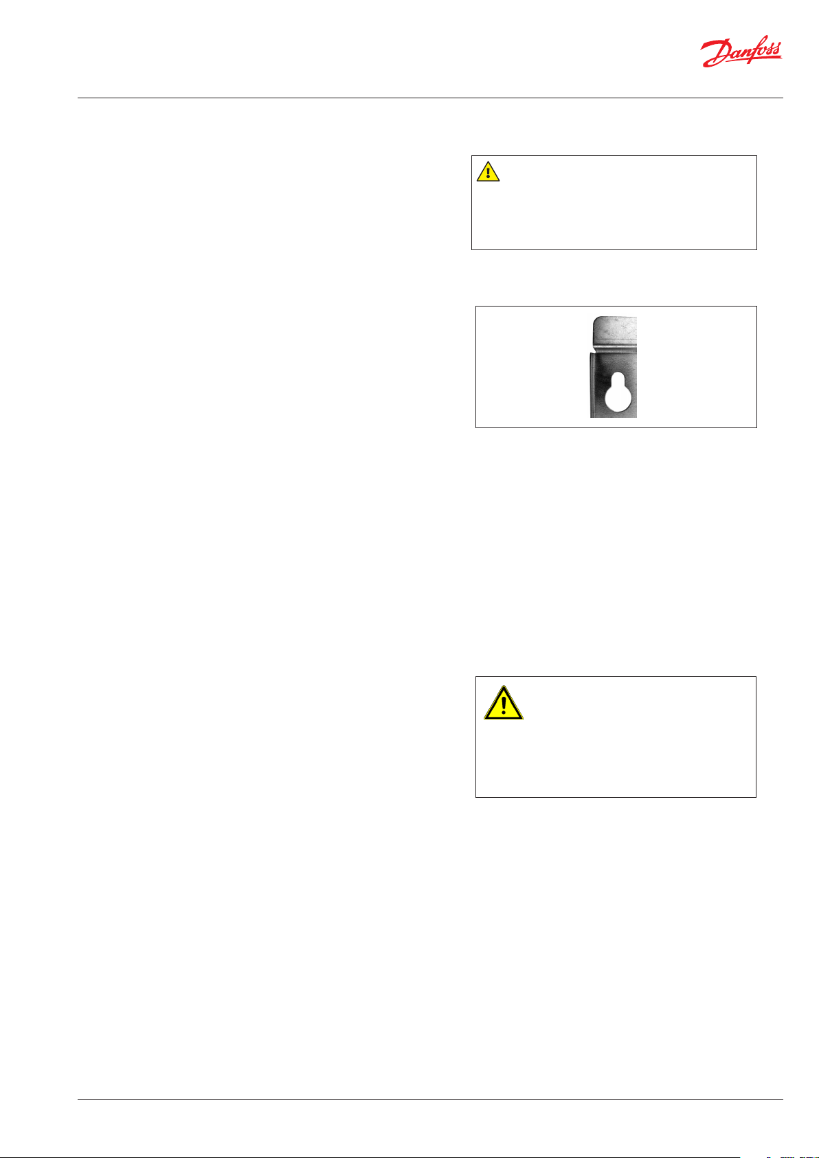
The station must be mounted so that components, keyholes and labels
are placed correctly. If you wish to mount the station differently please
contact your supplier.
Drillings
Where substations are to be wall-mounted, drillings are provided in the
back mounting plate.
Labelling
Each connection on the substation is labelled
Before installation:
Clean and rinse
Prior to installation, all substation pipes and connections should be cleaned
and rinsed.
Authorized personnel only
Assembly, start-up and maintenance work must be
performed by qualified and authorized personnel
only.
Keyhole for mounting.
Thightening
Due to vibration during transport, all substation connections must be
checked and tightened before installation. Check that all hairpins in click
connections are completely pushed in.
Unused connections
Unused connections and shut-off valves must be sealed with a plug.
Should the plugs require removal, this must only be done by an authorized
service technician.
Installation:
Strainer
If a strainer is supplied with the station it must be fitted according to schematic diagram. Please note that the strainer may be supplied loose.
Connections
Connection to the household installation and district heating pipes
connections must be made using threaded, flanged or welded connections.
The internal connections of the flat station are made by click-fit connections.
Please notice
Use of packaging types other than that with which the
device is delivered will void the warranty.
AQ15928645880503-020501
© Danfoss | Produced by Danfoss Redan A/S | 2020.12 | 5
Page 6

Mounting and installation instructions EvoFlat
3.2 Start-up
Start-up, Direct heating
The shut-off valves should be opened and the unit observed as it enters
service. Visual checking should confirm temperatures, pressures, acceptable
thermal expansion and absence of leakage.
If the heat exchanger operates in accordance with design, it can be put
to regular use.
After water has been added to the system and the system has been put
into operation, re-tighten ALL connections. Check that all hairpins in click
connections are completely pushed in.
Start-up, Heating with mixing loop
Start-up:
1: Pump speed
Set the pump to its highest speed of rotation before start-up. On radiator
systems, the selector switch is normally set in “Variable curve / Proportional
curve” setting, in “max. pos.”. For floor heating systems, the selector switch
is normally set in “Constant curve” setting, in “max. pos.”.
Re-thighten connections
After water has been added to the system and the system has been put into operation, re-tighten ALL connections.
Check that all hairpins in click connections are com-
pletely pushed in.
2: Start pump
Start the pump and heat through the system.
3: Open shut-off valves
The shut-off valves should then be opened and the unit observed as it
enters service. Visual checking should confirm temperatures, pressures,
acceptable thermal expansion and absence of leakage.
If the system operates in accordance with design, it can be put to regular
use, - always taking into account the conditions in the building.
4: Vent system
Switch off the pump and vent the installation after the system has been
warmed up. Please note that some pump types feature a built-in venting
function. For others the installation can be vented by using a vent valve
in the flat station or on the radiators, or, if appropriate, the air valve at the
highest point of the system – For additional information, please refers to
the enclosed pump and manual.
5: Adjust pump speed
Set the pump to the lowest possible position, depending on the heating
requirement for the building - taking into account aspects such as cooling
and power consumption.
If the heating requirement increases the pump setting can be changed
by means of the selector switch. Please refer to the enclosed instruction
manual for detailed information about setting ranges.
In the summer, you can switch off the power to the pump at the mains if
you want to save electricity by not heating your home. It should be ensured
that no inappropriate hydraulic situation will occur, when the power to
your pump is turned off.
For start-up and venting – see above and the enclosed pump manual.
6 | © Danfoss | Produced by Danfoss Redan A/S | 2020.12
AQ15928645880503-020501
Page 7

Mounting and installation instructions EvoFlat
3.3 Electrical connections
Before making electrical connections, please note the following:
Safety notes
Please read the relevant parts of the safety notes.
230 V
The flat station must be connected to 230 V AC and earth.
Disconnection
The substation must be electrically connected so that it can be disconnected for repairs.
Grounding / potential compensation
The station should be connected to a grounding point on the right side of
the station mounting rail.
Authorized electrician
Electrical connections must be made by an authorized
electrician only.
Local standards
Electrical connections must be made in accordance with
current regulations and local standards.
AQ15928645880503-020501
© Danfoss | Produced by Danfoss Redan A/S | 2020.12 | 7
Page 8

E
D
C
B
A
87
6
5
4
3
2
1
545
E
D
C
B
A
87
6
5
4
Mounting and installation instructions EvoFlat
4.0. MAIN COMPONENTS & DIMENSIONAL SKETCHES
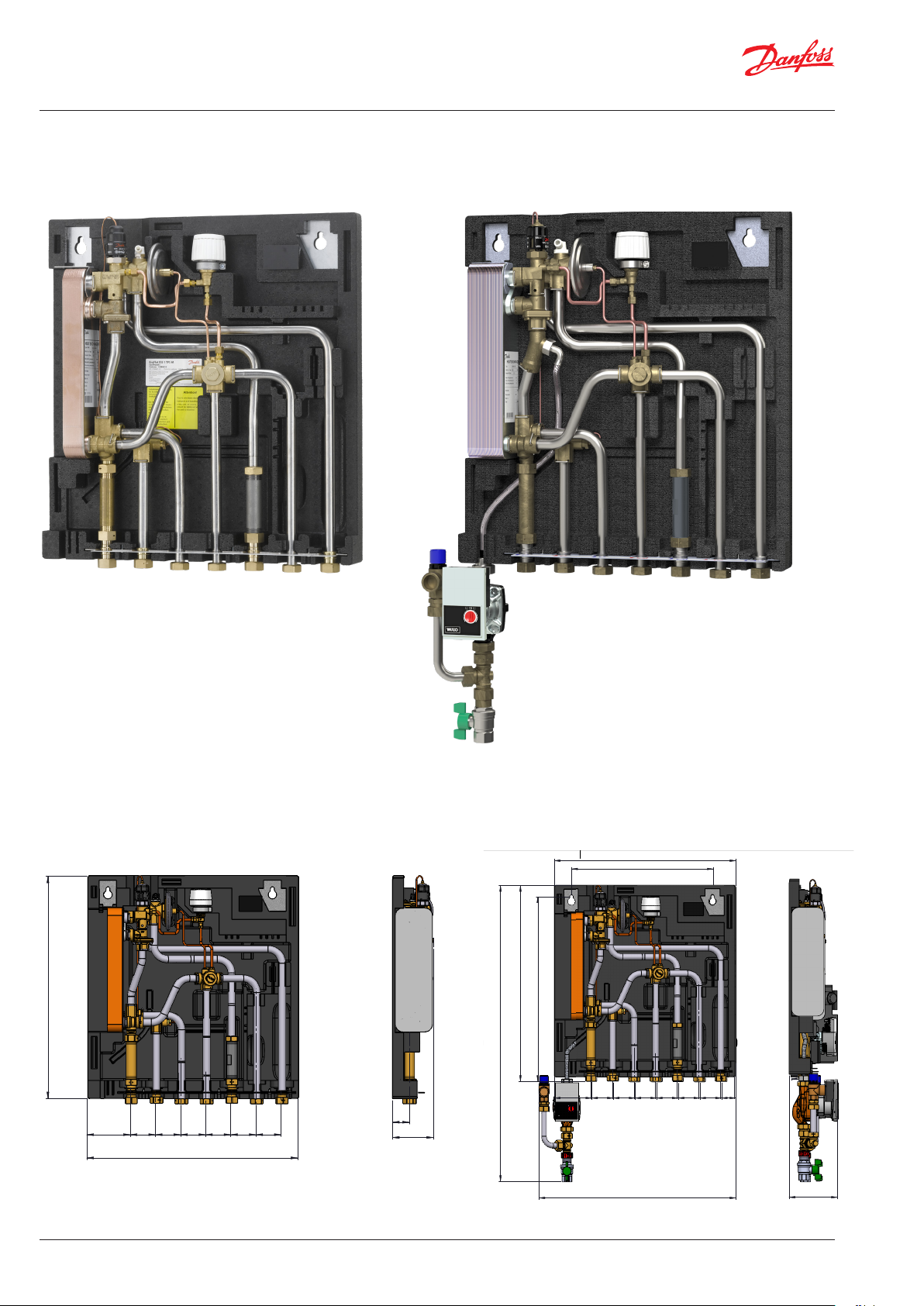
4.1 Construction WSS
17
38
2
23
59
Main components
WSS 1, 2, 3
2. Plate heat exchanger
5. Strainer
17. Air valve
23. Sensor pocket M10
24. Fitting piece, energy meter
38 DHW controller type TPC-M
40. Summer by-pass
59. Fitting piece, water meter
40
17
40
38
2
23
5
24
12
7
59
9
Main components
WSS 1, 2, 3, with circulation
2. Plate heat exchanger
5. Strainer
6. Non-return valve
7. Ball valve
6
9. Circulation pump
12. Safety valve
17. Air valve
23. Sensor pocket M10
24. Fitting piece, energy meter
38 DHW controller type TPC-M
40. Summer by-pass
59. Fitting piece, water meter
5
24
575
1 2 3 4 5
65 65 65 65 112
545
Your flat station might look different than the substation shown.
8 | © Danfoss | Produced by Danfoss Redan A/S | 2020.12
425
588,4
554,4
112 65 65 65 65 65 65 43
1 2
1. Domestic cold water (DCW)
1 Kaltwasser (KW) Eintritt
2 Warmwassser (WW)
2. Domestic hot water (DHW)
3 Kaltwasser (KW) Austritt
3. Domestic cold water (DCW)
4 Fernwärme (FW) Vorlauf
5 Fernwärme (FW) Rücklauf
4. District heating (DH) supply
6 Heizung (HE) Vorlauf
5. District heating (DH) return
7 Heizung (HE) Rücklauf
6. Circulation
6
3 4
582
5 6
7
142,4
44
105,4
889
AQ15928645880503-020501
Page 9
Mounting and installation instructions EvoFlat
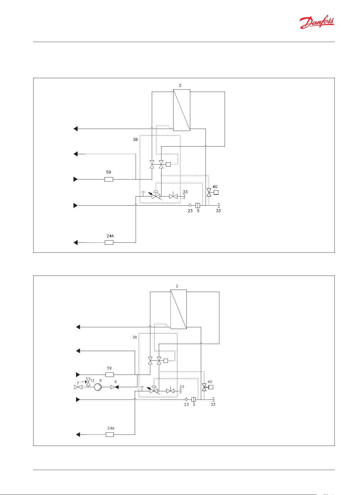
4,2 Diagrams, WSS
WSS 1, 2, 3
DHW
DCW
DCW
DH Supply
2. Plate heat exchanger
5. Strainer
23. Sensor pocket M10
24. Fitting piece, energy meter
33. Plug
38 DHW controller type TPC-M
40. Summer by-pass
59. Fitting piece, water meter
3/4” × 110 mm
3/4” × 110 mm
DH return
WSS 1, 2, 3, with circulation
DHW
DCW
DCW
Circulation
DH supply
2. Plate heat exchanger
5. Strainer
6. Non-return valve
7. Ball valve
9. Circulation pump
12. Safety valve
23. Sensor pocket M10
24. Fitting piece, energy meter
33. Plug
38 DHW controller type TPC-M
40. Summer by-pass
59. Fitting piece, water meter
Yonos Para Z 15/7
3/4” × 110 mm
3/4” × 110 mm
DH return
Your flat station might look different than the substation shown.
AQ15928645880503-020501
© Danfoss | Produced by Danfoss Redan A/S | 2020.12 | 9
Page 10
D
C
B
A
87
6
5
4
3
2
545
D
C
B
A
87
6
5
4
44
C
B
A
87
6
5
4
3
E
D
C
B
A
87
Mounting and installation instructions EvoFlat
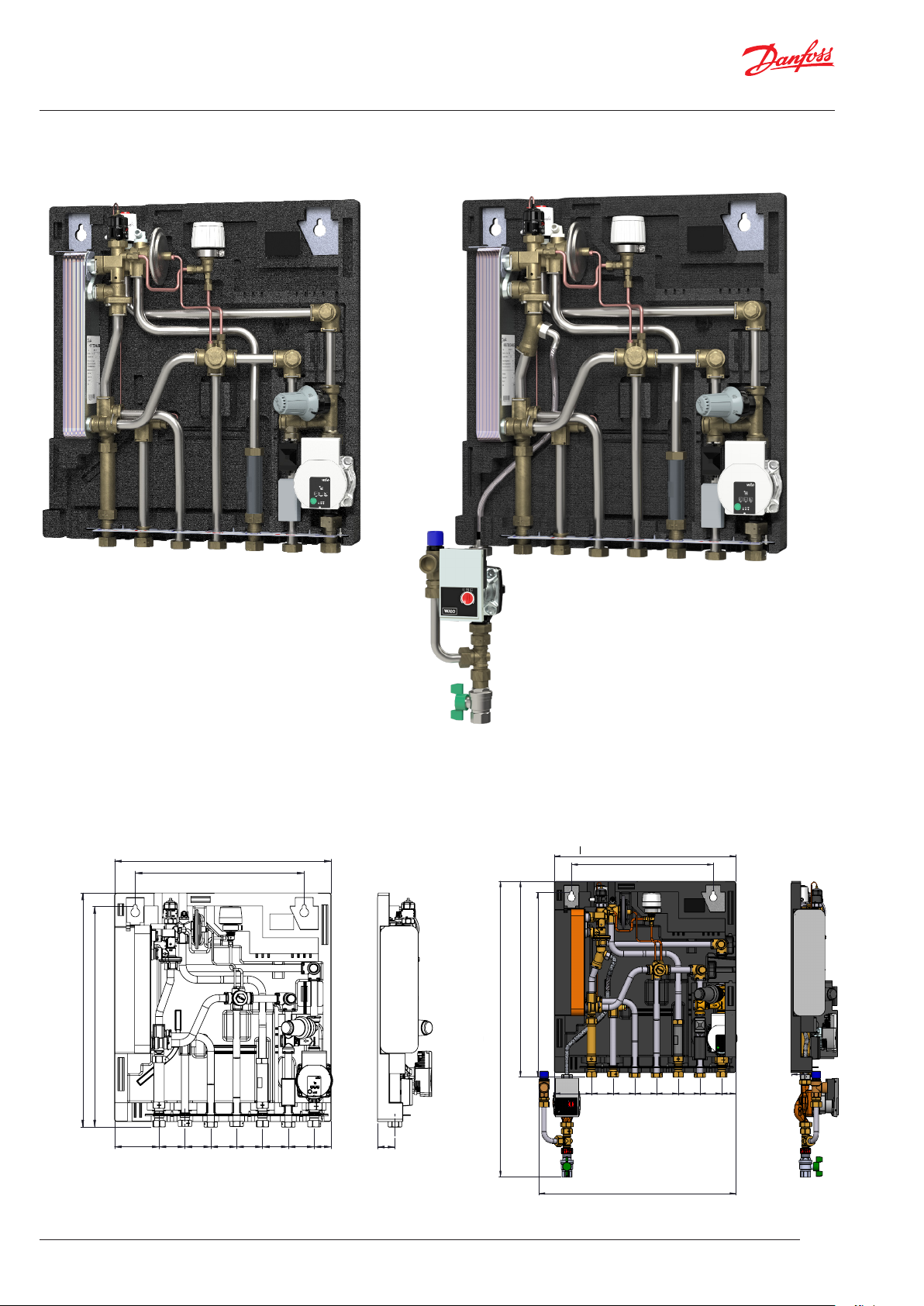
4.3 Construction FSS, Standard
17
40
38
2
23
5
59
Main components
FSS 1, 2, 3
2. Plate heat exchanger
5. Strainer
17. Air valve
23. Sensor pocket M10
24. Fitting piece, energy meter
38 DHW controller type TPC-M
40. Summer by-pass
59. Fitting piece, water meter
24
12
17
40
38
2
23
5
59
9
7
Main components
FSS1, 2, 3 with circulation
2. Plate heat exchanger
5. Strainer
6. Non-return valve
6
7. Ball valve
9. Circulation pump
12. Safety valve
17. Air valve
23. Sensor pocket M10
24. Fitting piece, energy meter
38 DHW controller type TPC-M
40. Summer by-pass
59. Fitting piece, water meter
24
545
44
105,4
575
112 65 65 65 65 65 65
1 2 3 4 5 6 7
Your flat station might look different than the substation shown.
10 | © Danfoss | Produced by Danfoss Redan A/S | 2020.12
425
588,4
554,4
889
112
65 65 65 65 65 65 43
1 2
1. Domestic cold water (DCW)
2. Domestic hot water (DHW)
3. Domestic cold water (DCW)
4. District heating (DH) supply
5. District heating (DH) return
6. HE supply
7. HE return
8. Circulation
8
3 4
5 6
1 Kaltwasser (KW) Eintritt
2 Warmwassser (WW)
3 Kaltwasser (KW) Austritt
4 Fernwärme (FW) Vorlauf
5 Fernwärme (FW) Rücklauf
6 Heizung (HE) Vorlauf
7 Heizung (HE) Rücklauf
591
44
7
142,4
AQ15928645880503-020501
Page 11
Mounting and installation instructions EvoFlat
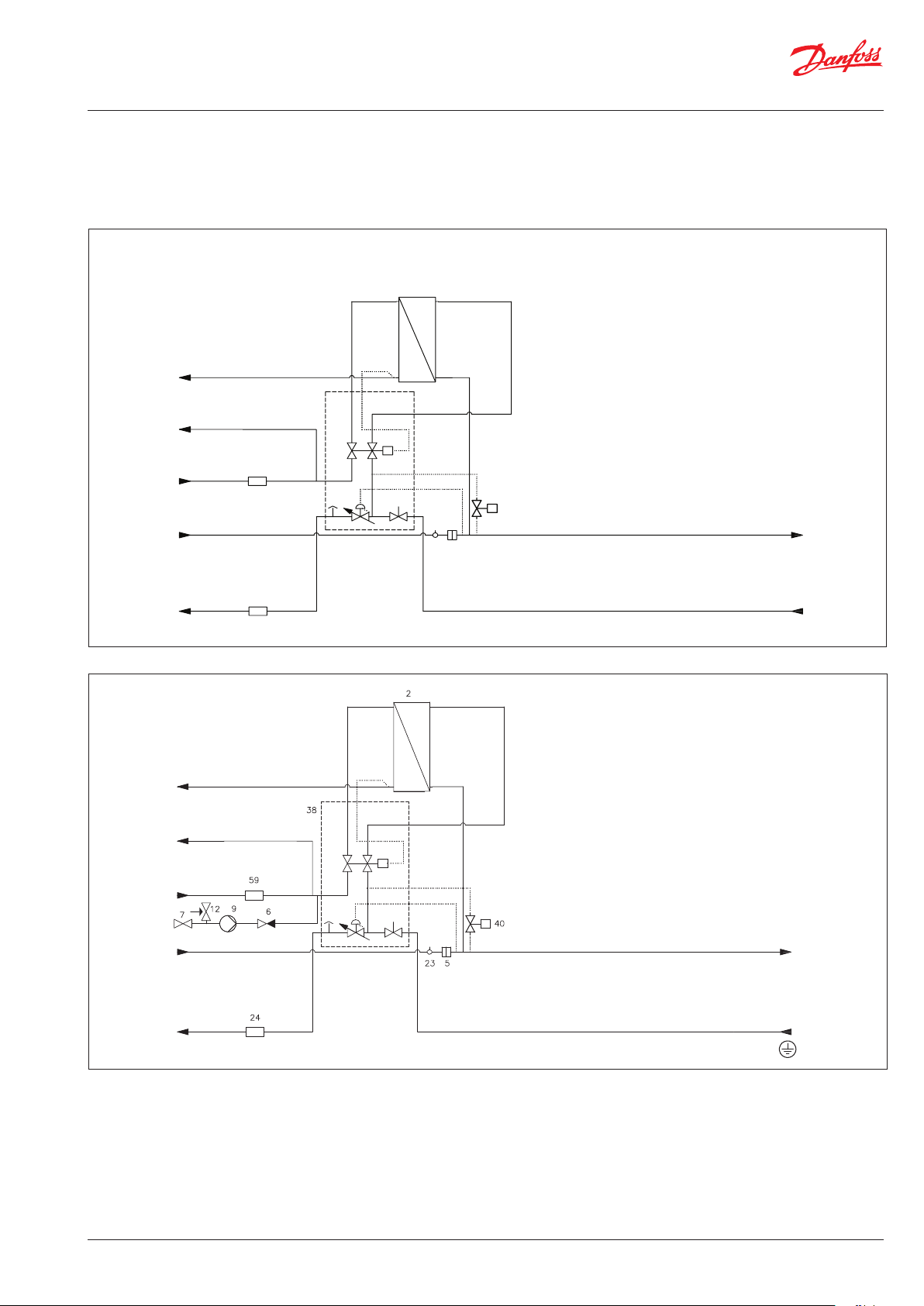
4.4 Diagrams, FSS Standard
FSS 1, 2, 3
2
27
DHW
38
DCW
2. Plate heat exchanger
5. Strainer
23. Sensor pocket M10
24. Fitting piece, energy meter
27. Temperature sensor DHW
38 DHW controller type TPC-M
40. Summer by-pass
59. Fitting piece, water meter
3/4” × 110 mm
3/4” × 110 mm
DCW
59
DH supply
24
DH return
FSS 1, 2, 3, with circulation
DHW
DCW
DCW
23 5
40
HE supply
HE return
2. Plate heat exchanger
5. Strainer
6. Non-return valve
7. Ball valve
9. Circulation pump
12. Safety valve
17. Air valve
23. Sensor pocket M10
24. Fitting piece, energy meter
38 DHW controller type TPC-M
40. Summer by-pass
59. Fitting piece, water meter
MW 0,6 mm
Yonos Para Z 15/7
3/4” × 110 mm
3/4” × 110 mm
Circulation
DH supply
DH return
Your flat station might look different than the substation shown.
4.4.1 EvoFlat Technical Parameters
Nominal pressure: PN10
Max. DH supply temperature: 95 °C
Min. DCW static pressure: 1,5 bar
Brazing material (HEX): Copper / Stainless steel
AQ15928645880503-020501
HE supply
HE return
© Danfoss | Produced by Danfoss Redan A/S | 2020.12 | 11
Page 12
545
D
C
B
A
87
6
5
4
E
D
C
B
A
87
6
5
4
Mounting and installation instructions EvoFlat
4.5 Construction, MSS Standard
38
17
23
40
5
29
30
17
40
38
2
23
5
29
30
2
6
54
59 24
MSS 1, 2, 3
2. Plate heat exchanger
5. Strainer
6. Non-return valve
10. Circulation pump, mixing circuit
17. Air valve
23. Sensor pocket M10
24. Fitting piece, energy meter
29. Actuator
30. Valve
38 DHW controller type TPC-M
40. Summer by-pass
54. Safety thermostat 55°C
59. Fitting piece, water meter
10
12
59
9
7
MSS 1, 2, 3 with circulation
2. Plate heat exchanger
5. Strainer
6. Non-return valve
7. Ball valve
9. Circulation pump, circulation
10. Circulation pump, mixing circuit
6
12. Safety valve
17. Air valve
23. Sensor pocket M10
24. Fitting piece, energy meter
29. Actuator
30. Valve
38 DHW controller type TPC-M
40. Summer by-pass
54. Safety thermostat 55°C
59. Fitting piece, water meter
545
425
425
24
54
10
588,4
554,4
65 65 65 65 65 65 43
112
1 2
3 4
5 6
7
44
Your flat station might look different than the substation shown.
12 | © Danfoss | Produced by Danfoss Redan A/S | 2020.12
588,4
889
554,4
112
65 65 65 65 65 65 43
3 4
1 2
1. Domestic cold water (DCW)
2. Domestic hot water (DHW)
1 Kaltwasser (KW) Eintritt
3. Domestic cold water (DCW)
2 Warmwassser (WW)
4. District heating (DH) supply
3 Kaltwasser (KW) Austritt
4 Fernwärme (FW) Vorlauf
5. District heating (DH) return
5 Fernwärme (FW) Rücklauf
6. HE supply
6 Heizung (HE) Vorlauf
7. HE return
7 Heizung (HE) Rücklauf
8. Circulation
8
591
5 6
44
7
AQ15928645880503-020501
Page 13
Mounting and installation instructions EvoFlat
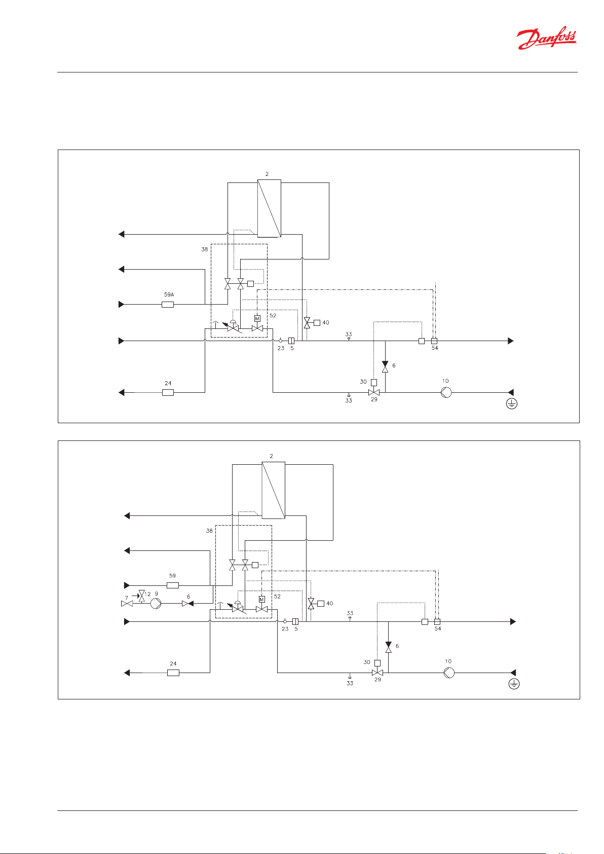
4.6 Diagrams, MSS Standard
MSS 1, 2, 3
DHW
DCW
DCW
2 Plate heat exchanger
5 Strainer MW 0,6 mm
6 Non-return valve
10
Circulation pump mixing circuit
Wilo Para 15/6
23
Sensor pocket
24
Fitting piece for energy meter
3/4” x 110 mm
29 Actuator
30 Valve
33 High-temperature connection
38 Hot Water Controller TPC-M
40 Summer-Bypass
52 Zone valve
54 Safety thermostat
59 Fitting piece for DCW:
3/4” × 110 mm
M10
DH supply
DH return
MSS 1, 2, 3, with circulation
DHW
DCW
DCW
Circulation
DH supply
2 Plate heat exchanger
5 Strainer MW 0,6 mm
6 Non-return valve
7 Ball valve
9 Circulation pump:
Yonos Para Z 15/7
10
Circulation pump mixing circuit
Wilo Para 15/6
12 Safety valve
HE supply
HE return
23
Sensor pocket
24
Fitting piece for energy meter
3/4” x 110 mm
29 Actuator
30 Valve
33 High-temperature connection
38 Hot Water Controller TPC-M
40 Summer-Bypass
52 Zone valve
54 Safety thermostat
59 Fitting piece for DCW:
3/4” × 110 mm
M10
HE supply
DH return
Your flat station might look different than the substation shown.
4.6.1 EvoFlat Technical Parameters
Nominal pressure: PN10
Max. DH supply temperature: 95 °C
Min. DCW static pressure: 1,5 bar
Brazing material (HEX): Copper / Stainless steel
AQ15928645880503-020501
HE return
© Danfoss | Produced by Danfoss Redan A/S | 2020.12 | 13
Page 14
Mounting and installation instructions EvoFlat
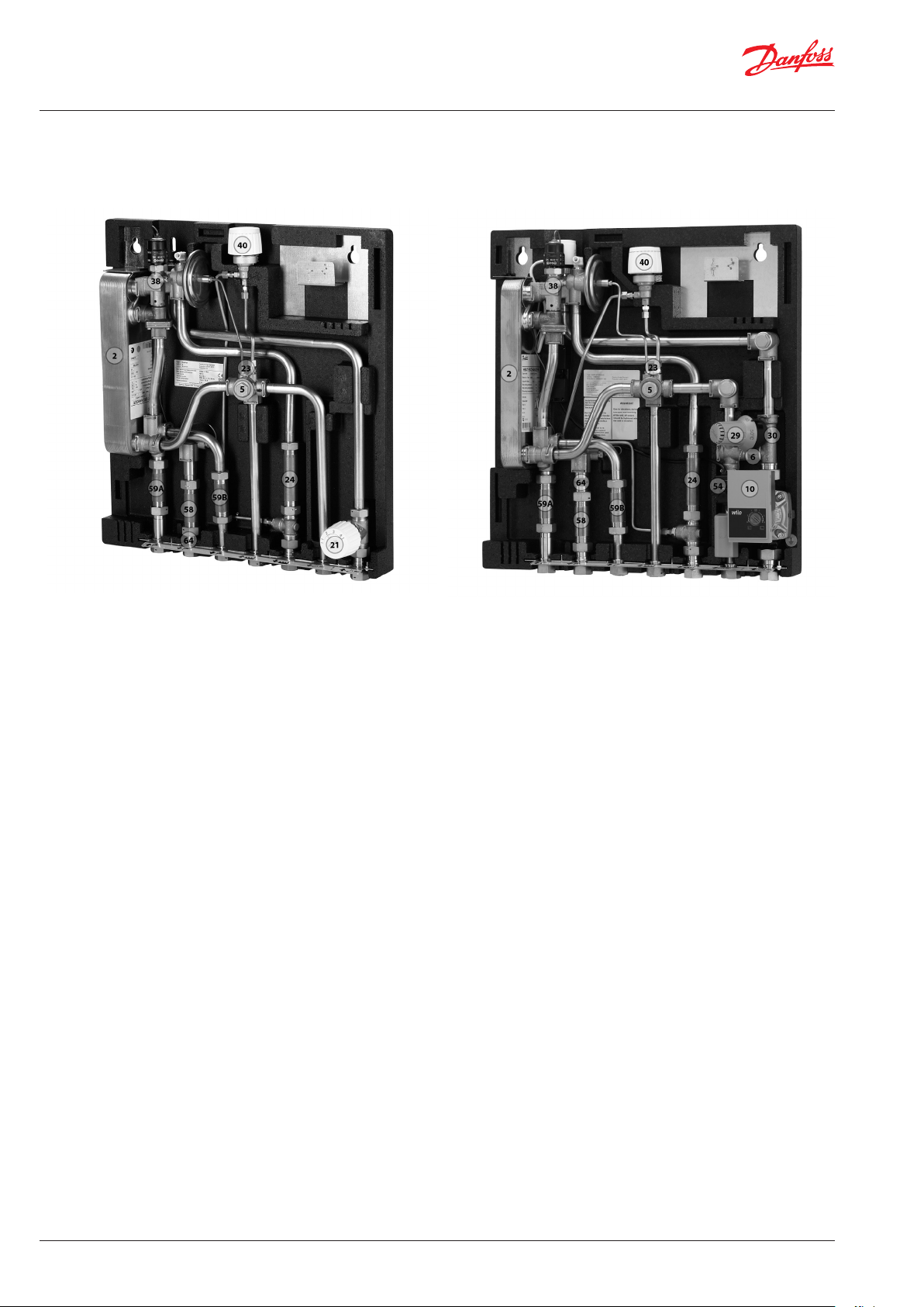
4.7 Construction, FSS & MSS A
Your flat station might look different than the substation shown.
Main components
FSS A1, A2, A3
17
17
MSS A1, A2, A3
2. Plate heat exchanger
5. Strainer
17. Air valve
21. Return temperature limiter
23. Sensor pocket M10
24. Fitting piece, energy meter
38 DHW controller type TPC-M
40. Summer by-pass
58. Fitting piece, water meter DHW
59A. Fitting piece, water meter DCW inlet
59B. Fitting piece, water meter DCW outlet
64. Flow limiter
2. Plate heat exchanger
5. Strainer
6. Non-return valve
10. Circulation pump mixing circuit
17. Air valve
23. Sensor pocket M10
24. Fitting piece, energy meter
29. Actuator
30. Valve
38 DHW controller type TPC-M
40. Summer by-pass
54. Safety thermostat 55°C
58. Fitting piece, water meter DHW
59A. Fitting piece, water meter DCW inlet
59B. Fitting piece, water meter DCW outlet
14 | © Danfoss | Produced by Danfoss Redan A/S | 2020.12
AQ15928645880503-020501
Page 15
Mounting and installation instructions EvoFlat
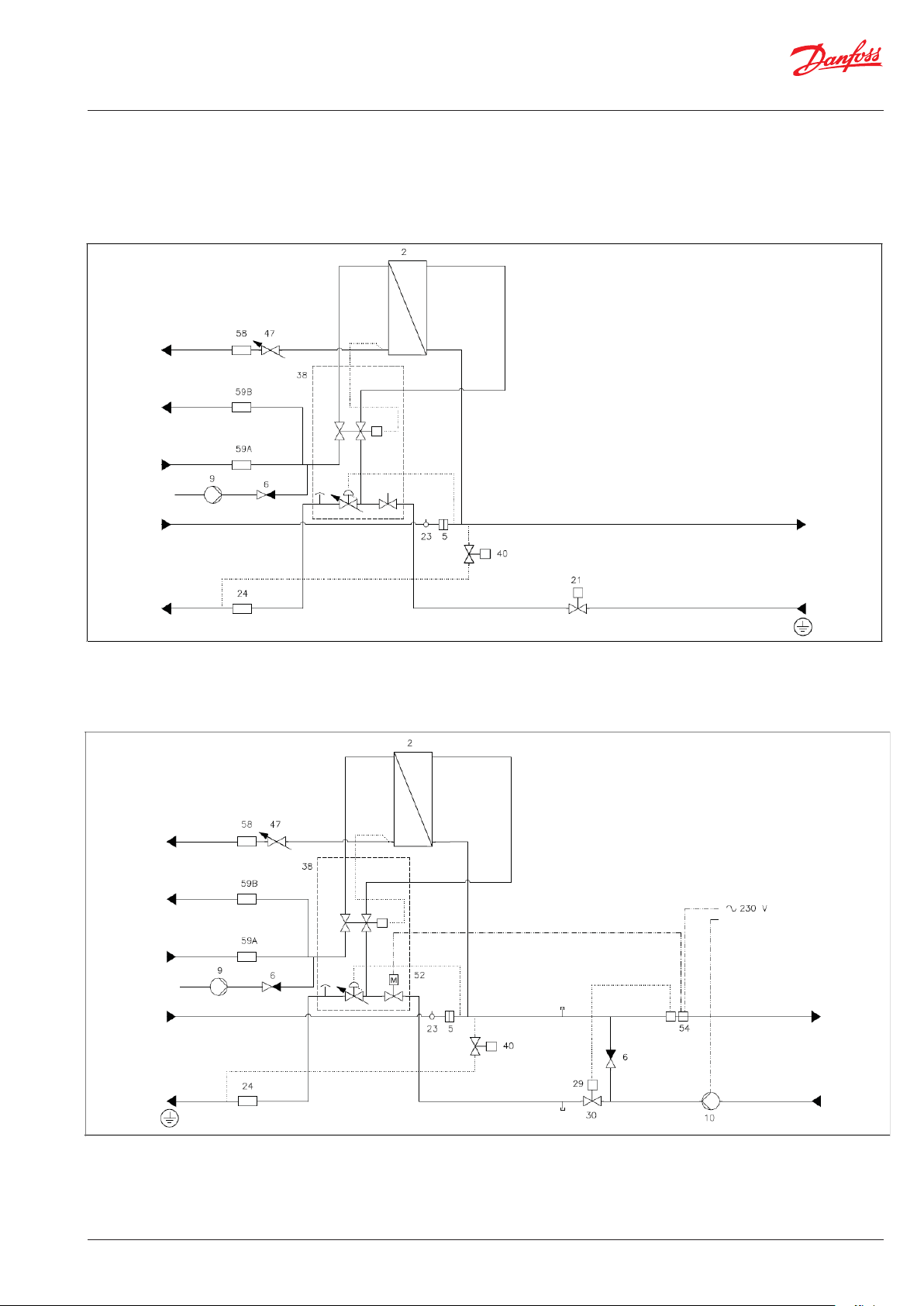
4.8 Diagrams, FSS & MSS A
FSS A1, A2, A3
DHW
DCW
DCW
DH supply
DH return
MSS A1, A2, A3
DHW
DCW
DCW
HE supply
HE return
DH supply
DH return
Your flat station might look different than the substation shown.
AQ15928645880503-020501
HE supply
HE return
© Danfoss | Produced by Danfoss Redan A/S | 2020.12 | 15
Page 16
Mounting and installation instructions EvoFlat
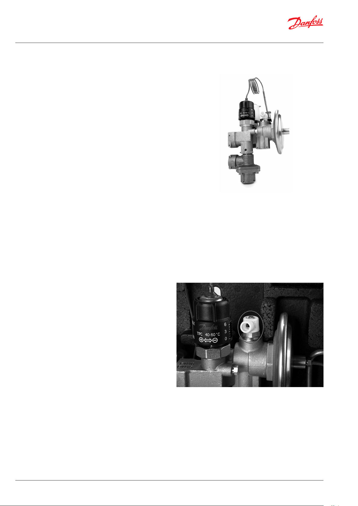
5.0. CONTROLS
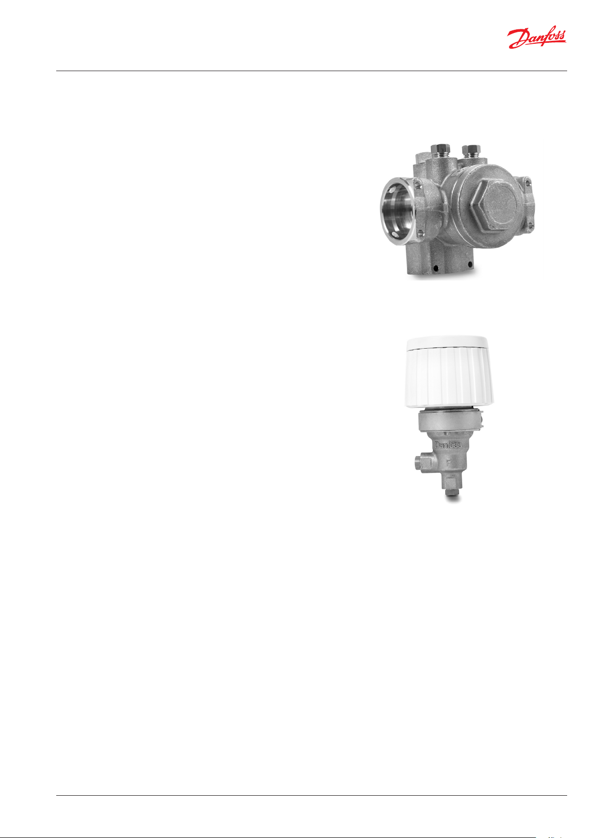
5.1 TPC multi-functional controller
Multi-functional controller with integrated zone valve, air vent, differential
pressure and PWH temperature controller.
PWH temperature control
direction the temperature is increased, by turning it in (-/MIN) direction
the temperature is decreased.
Setting range 40-60°C.
PWH temperature should be adjusted to 50 °C, as this provides optimal
utilization of DH water.
For systems with circulation, the hot water temperature must be 60 ° C and
the circulation return temperature must not fall below 55 ° C. (valid for DE).
Note: Systems with DHW circulation generate significantly higher heating
return temperatures in circulation mode than in full load mode
Differential pressure controller
The differential pressure controller equalizes the high fluctuations in pressure arriving from the heat source, ensuring constant operating pressure
The following applies to all EvoFlat stations:
At the “HE” connection, the available differential pressure is - depending
on volume flow (40 - 645 l / h) - between 220 - 165 mbar.
Zone valve
The TPC multi-functional controller contains a zone valve.
The TWA-Q/NC actuator can be mounted on the zone valve.
The transport protection on the TWA-Z/NC actuator must be removed
before use.
5.2 Air vent
The station should be vented during start up.
16 | © Danfoss | Produced by Danfoss Redan A/S | 2020.12
AQ15928645880503-020501
Page 17
Mounting and installation instructions EvoFlat
5.3 Strainer
Strainers should be cleaned regularly by authorized personnel. The
frequency of cleaning would depend on operating conditions.
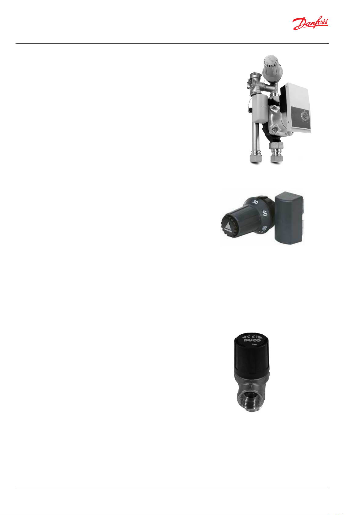
5.4 Summer bypass
The bypass thermostat is designed to keep the supply line warm.
Setting range: 10-50°C.
Scale setting (indicative).
Factory setting 2,5.
AQ15928645880503-020501
© Danfoss | Produced by Danfoss Redan A/S | 2020.12 | 17
Page 18
Mounting and installation instructions EvoFlat
5.5 Mixing loop
The mixing loop creates a suitable temperature level e.g. for floor
heating
5.6 FTC control
The FTC controls the mixing loop HE supply temperature.
Setting range 15-50°C.
The setting values may vary depending on the operating conditions. It is important to set the supply temperature to the radiators
as low possible.
NB! For houses that are heated exclusively with floor heating.
ALWAYS refer to the instructions from the floor supplier.
Factory setting: 50°C.
5.7 Safety thermostat
The safety thermostat will shut the zone valve if the HE supply
temperature is above 55°C.
5.8 Safety valve
The purpose of the safety valve is to protect the flat station from
excessive pressure.
The blow-off pipe from the safety valve must not be closed. The
blow-off pipe outlet should be placed so that it discharges freely
and it is possible to observe any dripping from the safety valve.
It is recommended to check the operation of safety valves at intervals of 6 months. This is done by turning the valve head in direction
indicated.
18 | © Danfoss | Produced by Danfoss Redan A/S | 2020.12
AQ15928645880503-020501
Page 19
Mounting and installation instructions EvoFlat
5.9 Return temperature limiter FJVR (10-55°C)
The return limiter type FJVR automatically controls the return temperature from heating system.
The return temperature limiter should be set to the required maximum return temperature, in compliance with the local demands.
Factory setting: 3.
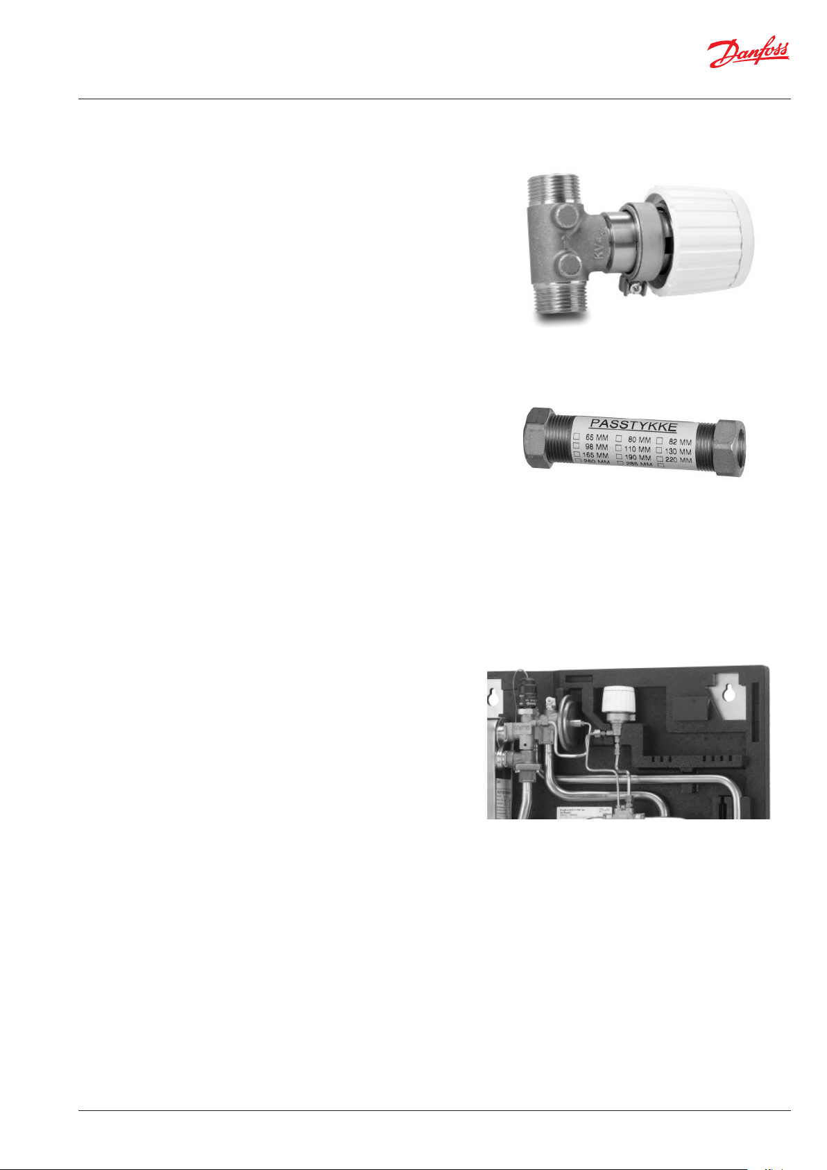
5.10 Fitting piece
The flatstation is equipped with a fitting piece for energy meter.
Mounting of energy meters:
1: Close ball valves
Close the ball valves on DH Supply and DH Return, if there is water
on the system.
2: Loosen nuts
Loosen the nuts on the fitting piece.
3: Remove fitting piece
Remove the fitting piece and replace it with the energy meter. Do
not forget the gaskets.
4: Tighten connections
After mounting of the energy meter remember to check and tighten all threaded connections.
5.11 Mounting bracket
Monting bracket for the heat meter display
The heat meter display can be fixed on the mounting bracket
which normally must be ordered separately. Check your heat meter supplier for more informations.
AQ15928645880503-020501
© Danfoss | Produced by Danfoss Redan A/S | 2020.12 | 19
Page 20
Mounting and installation instructions EvoFlat
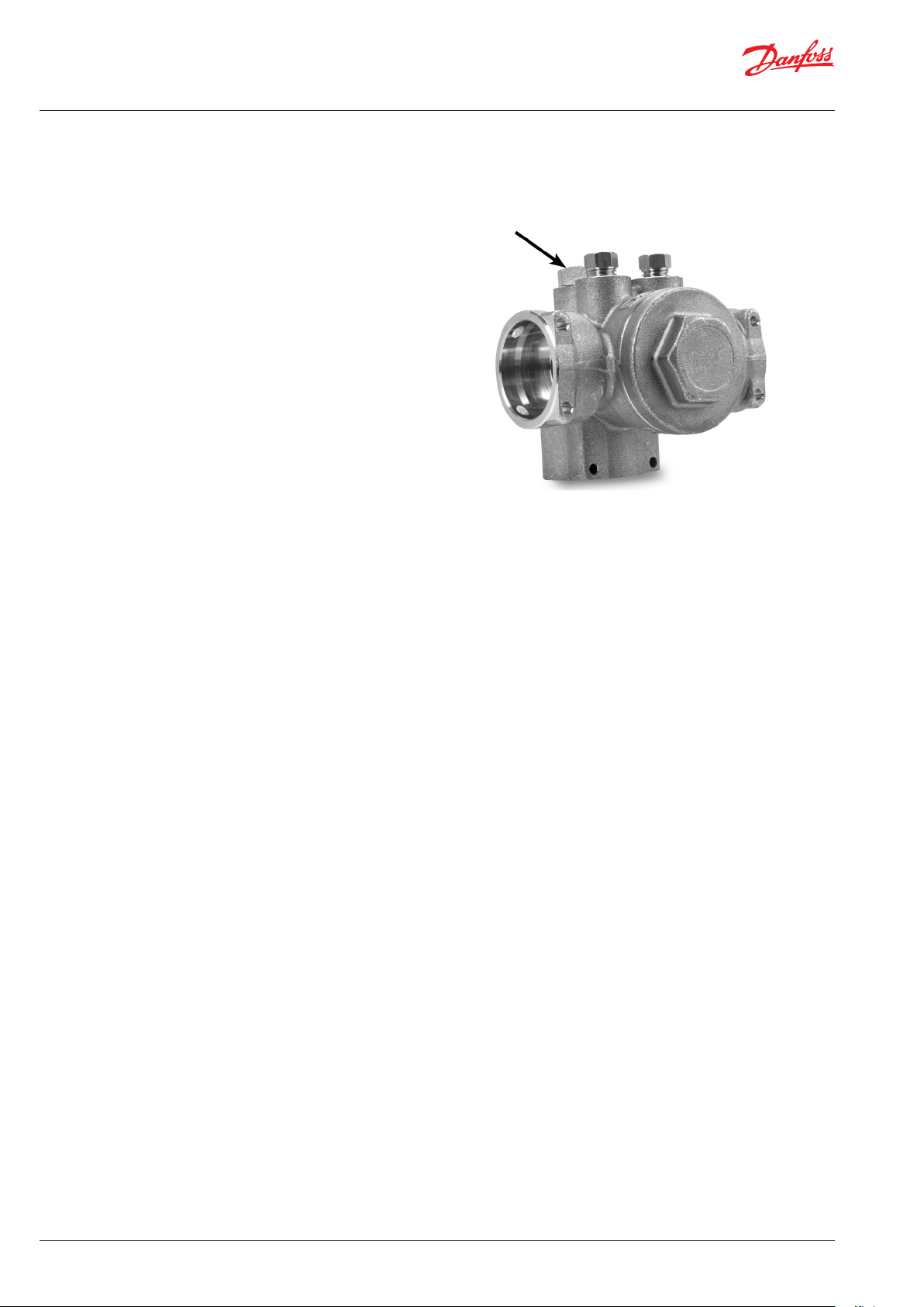
5.12 Sensor pocket, energy meter
The flow sensor of the heat meter is installed in the rear opening
(M10).
The sensor connection is located in the cross piece, where the filter
is also integrated.
20 | © Danfoss | Produced by Danfoss Redan A/S | 2020.12
AQ15928645880503-020501
Page 21
Mounting and installation instructions EvoFlat
6.0 MAINTENANCE
The flat station requires little monitoring, apart from routine checks. It
is recommended to read the energy meter at regular intervals, and to
write down the meter readings.
Regular inspections of the flat station according to this Instruction are
recommended, which should include:
Strainers
Cleaning of strainers.
Meters
Checking of all operating parameters such as meter readings.
Temperatures
Checking of all temperatures, such as HS supply temperature and
PWH temperature.
Connections
Checking all connections for leakages.
Safety valves
The operation of the safety valves should be checked by turning
the valve head in the indicated direction.
Venting
Checking that the system is thoroughly vented.
Authorized personnel only
Assembly, start-up and maintenance work must be performed by qualified and authorized personnel only.
Inspections should be carried out minimum every two years.
Spare parts can be ordered from Danfoss.
Please ensure that any enquiry includes the flat station serial number.
AQ15928645880503-020501
© Danfoss | Produced by Danfoss Redan A/S | 2020.12 | 21
Page 22
Mounting and installation instructions EvoFlat
7.0. TROUBLESHOOTING
7.1 Troubleshooting in general
6.1 Troubleshooting in general
In the event of operating disturbances, the following basic features
should be checked before carrying out actual troubleshooting:
• the flat station is connected to electricity,
• the strainer on the HS supply pipe is clean,
• the supply temperature of the HS is at the normal level,
• the differential pressure is equal to or higher than the normal
(local) differential pressure in the HS network – if in doubt, ask
the HS plant supervisor.
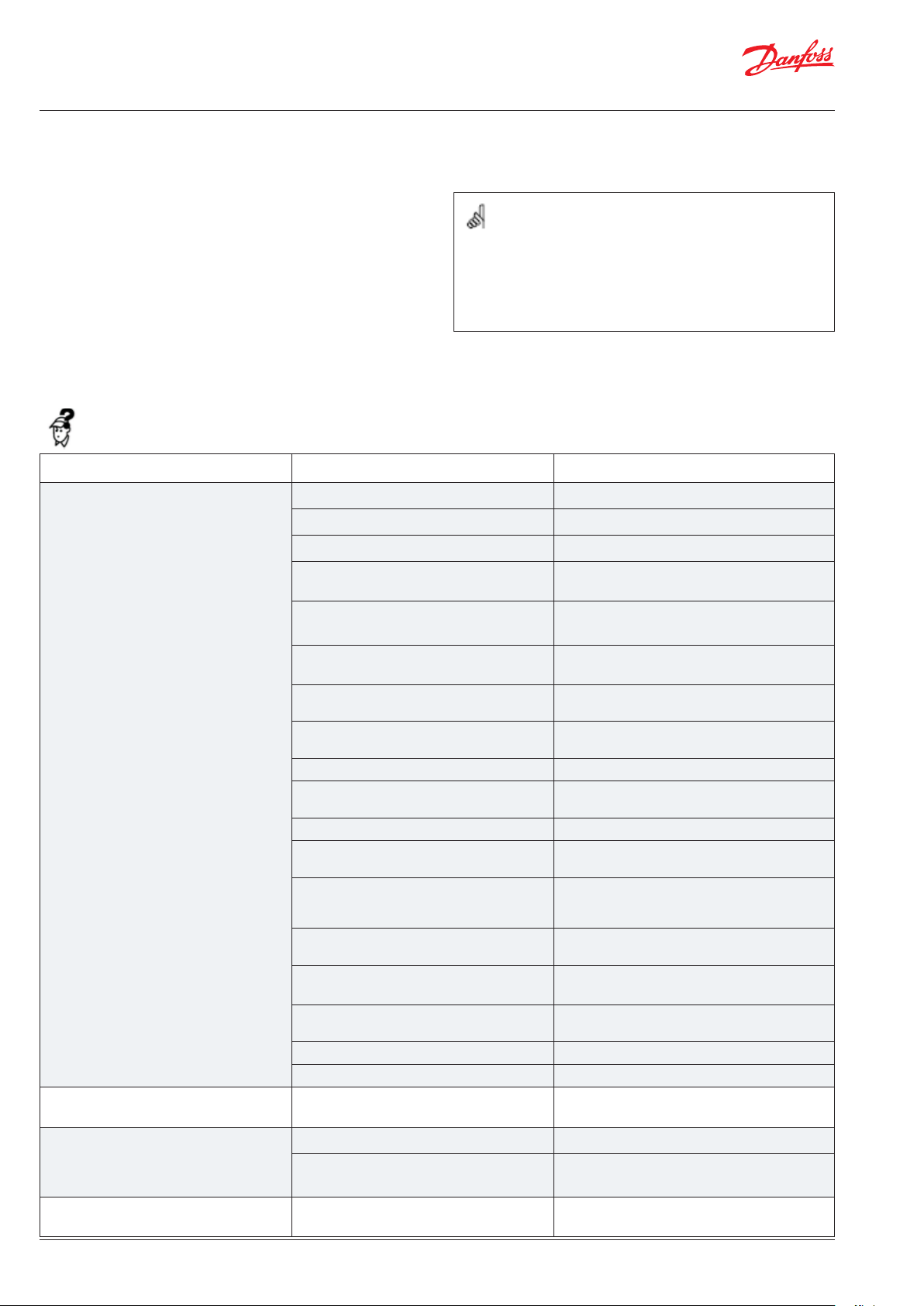
7.2 Troubleshooting: DHW
Problem Possible cause Solution
Too little or no domestic hot water Supply flow insufficient Collect data from the heat meter
Authorized personnel only
Assembly, start-up and maintenance work must be performed by qualified and authorized personnel only.
Check the network pump - constant pressure
If necessary, close the bypass in the tap block
Check the function of the ball valves and
open if necessary
Vent the system throughly - see the instruction
Change the summer bypass setting if necessary
Low temperature / variations in temperature at the draw-off points
Strainer in the cold water supply line
clogged.
Circulation pump out of operation , set at
too low speed of rotation (if DHW circulation is established)
Non-return valve defective or clogged (if
DHW circulation is established)
Defective DHW thermostat Check the functioning of the DHW thermo-
Defective TPC-M controller Check the functions of the controller,
Calified heat exchanger Replace heat exchanger
Lack of cold water pressure Increase pressure
DHW is available only at some draw-off
points.
DHW temperature too high DHW controller Adjust controller
Defective thermostatic mixing valve Replace thermostatic mixing valve
Collect data from the heat meter
Change the positioning time of the mixer
actuator
Change the heating curve if necessary
Position the switch-on sensor correctly on the
buffer line
Change cleaning periods for biomass boilers
Clean strainer
Check the function of the circulation pump
and replace if required
Check the functioning of the non-return valve
and replace if required
stat and repace if necessary
and replace if required
DHW controller defective Check the functions of the controller,
Temperature drop during tapping. Larger DHW flow than the flat station has
been designed for.
22 | © Danfoss | Produced by Danfoss Redan A/S | 2020.12
and replace if required
Reduce DHW flow
AQ15928645880503-020501
Page 23
Mounting and installation instructions EvoFlat
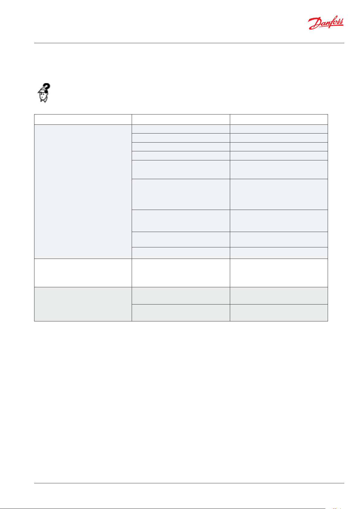
7.3 Troubleshooting HE
Problem Possible cause Solution
Too little or no heat. Strainer in supply line clogged Clean strainer(s)
The filter in the energy meter clogged. Clean the filter
Defective differential pressure controller. Replace main controller, TPC
Defective temperature sensors. Replace thermostat
Automatic controls, if any, wrongly set or
defective - possibly power failure.
Pump out of operation. Check if the pump is receiving power
Check if the setting of the controller
is correct – set coorectly or replace
and that it turns. Check if there is air
trapped in the pump housing.
See pump manual
The pump is set at too low speed of
rotation.
Air pockets in the system. Vent the system throughly - see the
Defective radiator valves. Check – replace
HS supply temperature too high. Defective TPC-M controller, alternative-
ly differential pressure controller. The
controller does not react as it should
according to the instructions.
Noise in system. Pump pressure too high. Noice from
radiator valves.
Mass flow below the control range Reduce the spread and thereby increase
Set the pump at higher speed of rotation.
See pump manual.
instruction
Replace TPC-M controller
Adjust pump to a lower level. Check flow
direction.
the mass flow
AQ15928645880503-020501
© Danfoss | Produced by Danfoss Redan A/S | 2020.12 | 23
Page 24
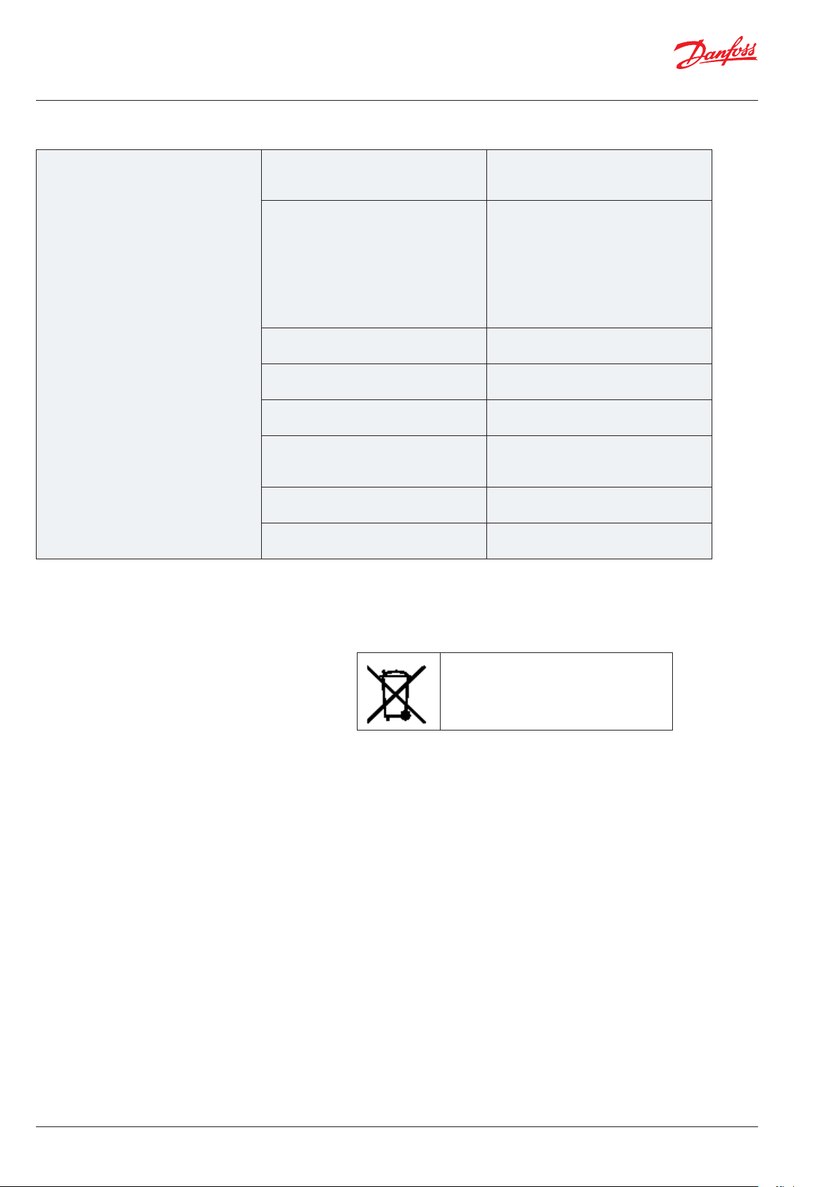
Mounting and installation instructions EvoFlat
Too high HS return temperature. Too small heating surface/too small
radiators compared to the total heating
requirement of the building.
Poor utilization of existing heating
surface.
Defective sensor on self-acting thermostat.
The system is single pipe loop. The system should be equipped with
Pump pressure too high. Set the pump at a lower speed of rota-
Air in system. Vent the system throughly - see the
Defective or incorrectly set radiator
valve(s). Single pipe loop systems require
special one-pipe radiator valves.
Dirt in the differential pressure controller.
Defective motorized valve, sensor or
automatic controller.
Increase total heating surface.
Make sure the heat is distributed evenly
across the full heating surface – open all
radiators and keep the radiators in the
system from heating up at the bottom.
It is extremely important to keep the
supply temperature to the radiators as
low as possible, while maintaining a
reasonable level of comfort.
electronic controls and return sensors.
tion. See pump manual.
instruction
Check – set/replace.
Check – clean out.
Check – replace.
7.4 Disposal
Disposal
This product should be dismantled and its components
sorted, if possible, in various groups before recycling
or disposal.
Always follow the local disposal regulations.
24 | © Danfoss | Produced by Danfoss Redan A/S | 2020.12
AQ15928645880503-020501
Page 25

Mounting and installation instructions EvoFlat
AQ15928645880503-020501
© Danfoss | Produced by Danfoss Redan A/S | 2020.12 | 25
Page 26

Mounting and installation instructions EvoFlat
8.0 DECLARATION
8.1 Declaration of conformity
Category 0 with electrical equipment
EU DECLARATION OF CONFORMITY
Danfoss Redan A/S
Hårupvænget 11
DK-8600 Silkeborg
Denmark
declares on our sole responsibility that the product(s)
EvoFlat
Covered by this declaration is in conformity with the following directive(s), standard(s) or other normative document(s), provided that the product is used in accordance with our instructions.
EMC – Directive – 2004/108/EC
EN 61000-6-1 2007. Electromagnetic compatibility – General standard:
Immunity for residential, commercial and light
industry
EN 61000-6-3 2007. Electromagnetic compati-
Machinery Directive 2006/42/EC
EN 14121-1. Safety of machinery – Risk assessment
EN 60204-1. Safety of machinery – Electrical
equipment of machines – Part 1:
General requirements.
bility – Generic standard:
Emission for residential, commercial & light
industry.
Pressure Equipment Directive – 97/23/EC
Equipment category: 0 (article 3.3).
Silkeborg - 08-10.2014
Place and date of issue Henrik Daugaard
Thomas Bruun Hansen
26 | © Danfoss | Produced by Danfoss Redan A/S | 2020.12
AQ15928645880503-020501
Page 27

Mounting and installation instructions EvoFlat
AQ15928645880503-020501
© Danfoss | Produced by Danfoss Redan A/S | 2020.12 | 27
Page 28

28 | © Danfoss | Produced by Danfoss Redan A/S | 2020.12
AQ15928645880503-020501
Page 29

Montage- und Betriebsanleitung
EvoFlat Wohnungsstationen für
Wohnungen, Ein- und Mehrfamilienhäuser
Komplett Wärmegedämmte Wohnungsstationen für direkte Beheizung mit Trinkwasser-Erwärmung im Durchfluss
EvoFlat
Wohnungsstation für
Wohnungen, Ein- und
Mehrfamilienhäuser
www.fernwärme.danfoss.de
Page 30

Montage- und Betriebsanleitung EvoFlat
EvoFlat FSS
EvoFlat WSS , mit Zirkulation
EvoFlat MSSEvoFlat WSS
EvoFlat MSS, mit ZirkulationEvoFlat FSS, mit Zirkulation
1. INHALT
1.0 Inhaltsverzeichnis ............................................................................................................................................................................ 2
2.0 Sicherheitshinweise......................................................................................................................................................................... 3
2.1 Allgemeine Sicherheitshinweise ................................................................................................................................................................3
3.0 Montage ............................................................................................................................................................................................ 5
3.1 Montage ..........................................................................................................................................................................................................5
3.2 Inbetriebnahme .............................................................................................................................................................................................6
3.3 Elektrische Anschlüsse ..................................................................................................................................................................................7
4.0 Auau ............................................................................................................................................................................................... 8
4.1 Auau & Massskizzen, WSS........................................................................................................................................................................8
4.2 Schematisch, WSS Darstellung ...................................................................................................................................................................9
4.3 Auau & Massskizzen, FSS Standard ......................................................................................................................................................10
4.4 Schematisch, FSS Darstellung ...................................................................................................................................................................11
4.5 Auau & Massskizzen, MSS Standard ....................................................................................................................................................12
4.6 Schematisch, MSS Darstellung .................................................................................................................................................................13
4.7 Auau & Massskizzen, FSS & MSS A .......................................................................................................................................................14
4.8 Schematisch, FSS & MSS A Darstellung ..................................................................................................................................................15
5.0 Regelkomponente .......................................................................................................................................................................... 16
6.0 Wartung .......................................................................................................................................................................................... 21
7.0 Fehlersuche ..................................................................................................................................................................................... 22
7.1 Allgemeine Fehlersuche .............................................................................................................................................................................22
7.2 Fehlersuche: WW-Versorgung ..................................................................................................................................................................22
7.3 Problemlösung Heizung .............................................................................................................................................................................23
7.4 Entsorgung ....................................................................................................................................................................................................24
8.0 Erklärung ......................................................................................................................................................................................... 26
8.1 Konformitätserklärung......................................................................................................................................................... 26
30 | © Danfoss | Produced by Danfoss Redan A/S | 2020.12
AQ15928645880503-020501
Page 31

Montage- und Betriebsanleitung EvoFlat
2.0 SICHERHEITSHINWEISE
2.1 Allgemeine Sicherheitshinweise
Die folgende Anleitung bezieht sich auf das Standarddesign der Station.
Vor der Installation und Inbetriebnahme der Station sollte diese Betriebsanleitung aufmerksam durchgelesen werden. Der Hersteller übernimmt
keine Haftung für Schäden oder Defekte, die aus der Missachtung der Betriebsanleitung resultieren. Bitte lesen und befolgen Sie sämtliche Hinweise,
um Unfälle, Verletzungen und Sachschäden zu vermeiden.
Aufbau, Inbetriebnahme und Wartungsarbeiten dürfen nur von qualifizierten und autorisierten Fachleuten durchgeführt werden.
Beachten Sie bitte die Vorgaben des Systemherstellersund des Anlagenbetreibers.
Korrosionsschutz
Alle Rohre und Komponenten bestehen aus Edelstahl und Messing.
Der maximale Chloridgehalt des Mediums sollte 150 mg/l NICHT übersteigen.
Das Risiko von Korrosionsschäden steigt beträchtlich an, wenn der empfohlene Chloridgehalt in Abhängigkeit von der Temperatur überschritten
wird.
Wärmeversorgung
Die Wohnungsstationen können an Fernwärme oder Heizsystemen mit
unterschiedli chen Energiequellen (zentraler Kessel mit Gas, Öl oder Biomasse befeuert), Solarenergie, Wärmepumpe, KWK-Anlagen oder eine Kombination aus diesen angeschlossen werden. Die Betriebsbedingungen der
Wohnungsstationen müssen eingehalten werden.
Anwendung
Die Wohnungsstation ist ausschließlich für die Erwärmung von Wasser
konzipiert. Die Wohnungsstation muss in einem frostfreien Raum installiert werden, wo die Raumtemperatur nicht über 50 °C steigt und die Luftfeuchtigkeit 80% nicht überschreitet. Die Station darf weder zugestellt
noch eingemauert werden, und der freie Zugang zur Station muss stets
gewährleistet sein.
Materialwahl
Die Materialwahl erfolgt stets gemäß den geltenden örtlichen Vorschriften.
Sicherheitsventil(e)
Es sind stets die geltenden örtlichen Vorschriften einzuhalten.
Nur autorisierte Fachkräfte
Aufbau, Inbetriebnahme und Wartungsarbeiten dürfen
nur von qualifizierten und autorisierten Fachleuten
durchgeführt werden.
Bitte beachten Sie Hinweise in dieser Anleitung.
Um Personenschäden und eine Beschädigung des Geräts zu verhindern, muss diese Anleitung genau beachtet
werden.
Warnung vor hohem Druck und hohen Temperaturen
Beachten Sie den erlaubten Systemdruck und die Systemtemperatur der Installation.
Die Höchsttemperatur in der Station beträgt 95 °C.
Der maximale Betriebsdruck der Station beträgt 10 bar.
Das Risiko von Personenschäden und beschädigter Einbauteile nimmt beträchtlich zu, wenn die empfohlenen
zulässigen Betriebsparameter überschritten werden.
Die Installation ist mit Sicherheitsventilen auszustatten,
wenn dies die landesspezifischen Vorschriften vorsehen.
Warnung vor heißen Oberflächen
Die Station hat heiße Oberflächen, die zu Verbrennungen
der Haut führen können. Seien Sie bitte in der Nähe der Station sehr vorsichtig.
Bei einem Stromausfall kann es passieren, dass die Motorventile geöffnet bleiben. Die Oberflächen der Station
können sehr heiß werden und dann bei Berührung zu Hautverbrennungen führen. Die Kugelhähne an Versorgungsvor- und -rücklauf sollten geschlossen werden.
Geräuschpegel
≤ 35 dB
Anschlussart
Die Station muss bauseits mit Vorrichtungen versehen sein, die sicherstellen, dass die Station von sämtlichen Energiequellen einschließlich der
Spannungsversorgung getrennt werden kann.
Notfälle
Bei Gefahr oder Unfällen (wie z. B. durch Feuer, Leckagen oder sonstige
gefährliche Umstände) sollten – sofern möglich – sämtliche Energiequellen
von der Station getrennt werden. Außerdem sollten Fachleute hinzugezogen werden.
Bei verfärbtem oder übel riechendem Trinkwarmwasser sollten sämtliche
Kugelhähne an der Station geschlossen werden.
Informieren Sie zudem den zuständigen Betreiber / Fachhandwerker.
Lagerung und Handhabung
Muss die Station vor der Installation gelagert werden, so hat dies unter
trockenen und frostfreien Bedingungen zu erfolgen.
AQ15928645880503-020501
Warnung vor Transportschäden
Stellen Sie bitte vor der Installation der Station sicher, dass
die Station beim Transport nicht beschädigt wurde.
WICHTIGER HINWEIS: Anschlüsse nachziehen
Wegen der Erschütterungen während des Transports
müssen alle Schraubverbindungen sowie sämtliche elektrischen Klemm- und Schraubanschlüsse überprüft und
ggf. nachgezogen werden, bevor die Anlage mit Wasser
befüllt wird.
Nachdem die Anlage mit Wasser befüllt und in Betrieb
genommen wurde, ist ein erneutes Nachziehen ALLER
Verschraubungen erforderlich. Überprüfen Sie, dass alle
Stifte der Click-Fit-Anschlüsse vollständig eingesteckt
sind.
© Danfoss | Produced by Danfoss Redan A/S | 2020.12 | 31
Page 32

Montage- und Betriebsanleitung EvoFlat
Reach
Sämtliche Produkte der EvoFlat Reno Serie erfüllen die Bestimmungen der
REACH-Verordnung.
Wir sind dem gemäß verpflichtet unsere Kunden über das Vorhandensein von
Stoffen laut SVHC Kandidatenliste zu informieren so diese vorhanden sind.
Hiermit informieren wir Sie: Dieses Produkt enthält Messingteile die Blei
(CAS 7439-92-1) in einer Konzentration über 0,1% Massenprozent enthalten.
Potentialausgleich / Erdung
Unter Potentialausgleich versteht man alle Maßnahmen zum Beseitigen
elektrischer Potentialunterschiede (Kontaktspannungen),
die zwischen z.B zwei Rohrleitungen auftreten können. Der Potentialausgleich ist eine wichtige Maßnahme zum Schutz gegen elektrischen Schlag.
Potentialausgleich reduziert Korrosion im Wärmetauscher, Durchlauferhitzer,
Wohnungsstationen und Sanitärinstallationen. Potentialausgleich sollte nach
den Bestimmungen 60364-4-41: 2007 und IEC 60364-5-54: 2011 erfolgen.
Verbindungsstelle ist mit einem Erdungssymbol auf der rechten unteren Ecke
der Montageplatte markiert und es gibt ein Loch in der Montageplatte und
ein Etikett mit Erdungssymbol.
Entsorgung
Die Station besteht aus Materialien, die nicht zusammen mit dem Hausmüll
entsorgt werden dürfen. Die gesammte Energieversorgung unterbrechen
und zerlegen Sie das Produkt zur entsorgung in Einzelteile und führen Sie sie
gemäß den geltenden örtlichen Vorschriften sortenrein der Entsorgung zu.
Bitte bemerken
Eingriffe und Nacharbeiten an unseren Komponenten
führen zum Verlust der Gewährleistung.
32 | © Danfoss | Produced by Danfoss Redan A/S | 2020.12
AQ15928645880503-020501
Page 33

Montage- und Betriebsanleitung EvoFlat
3. MONTAGE
3.1 Montage
Die Installation muss den landesspezifischen Normen und Richtlinien und
dem neusten anerkannten Regeln der Technik entsprechen.
Wärmequelle: In den folgenden Abschnitten bezeichnet WQ die Wärmequelle, die die Wohnungsstationen versorgt. Eine Vielzahl von Energiequellen, wie z. B. Öl, Gas oder Solarenergie,kann als Hauptenergiequelle
für die Wohnungsstationen von Danfoss verwendet werden.
Montage
Ausreichende Abstände
Lassen Sie um die Station herum ausreichende Abstände für Installationsund Wartungsarbeiten.
Ausrichtung:
Die Station muss so montiert werden, dass alle Bauteile, Bohrlöcher und
Typenschilder ordnungsgemäß positioniert sind. Falls Sie die Station auf
andere Weise montieren möchten, wenden Sie sich an Ihren Händler.
Bohrlöcher:
Zur Montage der Station nutzen Sie bitte die in der Rückenplatte vorgesehenen Bohrlöcher.
Beschriftung:
Jeder Anschluss der Station ist beschriftet.
Vor dem Einbau:
Reinigen und spülen
Vor der Montage der Wohnungsstation muss das Rohrnetz gereinigt bzw.
gespült werden.
Nur autorisierte Fachkräfte
Aufbau, Inbetriebnahme und Wartungsarbeiten dürfen nur von qualifizierten und autorisierten Fachleuten durchgeführt werden.
Bohrloch für die Wandmontage.
Nachziehen:
Aufgrund von Erschütterungen während des Transports müssen alle Anschlüsse der Station vor der Installation kontrolliert und nachgezogen
werden. Überprüfen Sie, dass alle Stifte der Click-Fit-Anschlüsse vollständig eingesteckt sind.
Nicht verwendete Anschlüsse:
Nicht verwendete Anschlüsse und Absperrventile müssen mit einem Stopfen verschlossen werden. Müssen die Stopfen entfernt werden, darf dies
nur durch einen autorisierten Fachleuten geschehen. Landesspezifischen
Vorschriften sind einzuhalten.
Einbau:
Schmutzfänger
Im Lieferumfang der Station ist ein Schmutzfänger enthalten. Dieser muss
gemäß der schematischen Darstellung eingebaut und regelmäßig gereinigt
werden.
Anschlüsse:
Die Anschlüsse an die Hausinstallation und die Fernwärmeleitungen sind
mit Gewinde, Flansch oder Schweißenden auszuführen.
Die internen Anschlüsse der Wohnungsstation sind Click-Fit-Anschlüsse
Bitte bemerken
Verwendung anderer Verpackungsarten, als die, mit
denen das Gerät geliefert wird, führen zum Verlust der
Gewährleistung.
AQ15928645880503-020501
© Danfoss | Produced by Danfoss Redan A/S | 2020.12 | 33
Page 34

Montage- und Betriebsanleitung EvoFlat
3.2 Inbetribnahme
Inbetriebnahme, direktes Heizen
Während der Inbetriebnahme müssen die Absperrventile geöffnet sein
und das Gerät überwacht werden. Prüfen Sie die Temperaturen, Drücke,
thermische Ausdehnung und die Dichtigkeit. Sobald der Wärmeübertrager
ordnungsgemäß arbeitet, kann das Gerät seinen bestimmungsgemäßen
Betrieb aufnehmen.
Das Befüllen der Anlage und der Station(en) muss über den Vorlauf erfolgen.
Ist die Anlage befüllt, ist der Filter zu prüfen und ggf. zu reinigen.
Nachdem die Anlage mit Wasser befüllt und in Betrieb genommen wurde,
kann ein erneutes Nachziehen erforderlich sein. Überprüfen Sie, dass alle
Stifte der Click-Fit-Anschlüsse vollständig eingesteckt sind.
Inbetriebnahme, Heizung mit Mischkreis
Inbetriebnahme:
1: Pumpendrehzahl
Die Pumpe ist nach dem Einschalten auf die der Anzahl der Heizkreise
entsprechenden Drehzahl einzustellen.
Die Einbau- und Betriebsanleitung des Herstellers der Umwälzpumpe ist
zu beachten.
Anschlüsse erneut festziehen
Nachdem die Anlage mit Wasser befüllt und in Betrieb
genommen wurde, ist ein erneutes Nachziehen ALLER Verschraubungen erforderlich. Überprüfen Sie,
dass alle Stifte der Click-Fit-Anschlüsse vollständig
eingesteckt sind.
2: Pumpe starten
Pumpe starten und System durchheizen.
Hinweise, die bei Montage, Betrieb und Wartung beachtet werden müssen, sind der beigelegten Einbau- und Betriebsanleitung der Hersteller zu
entnehmen.
3: Absperrventile öffnen
Jetzt müssen die Absperrventile geöffnet und die Station überwacht
werden. Prüfen Sie die Temperaturen, Volumenströme und die Dichtigkeit. Wenn das System ordnungsgemäß funktioniert kann die Station in
Betrieb genommen werden.
4: System entlüften
Pumpe ausschalten und die Station entlüften, nachdem das System aufgewärmt wurde. Bitte beachten Sie, dass einige Pumpentypen über eine
eingebaute Entlüftungsfunktion verfügen. Andere Installationen können
unter Verwendung eines manuellen Entlüfters in der Wohnungsstation
oder an den Heizkörpern / Heizkreisverteilern oder, wenn möglich, über
das Lüftungsventil am obersten Punkt des Systems, entlüftet werden. Für
weitere Informationen lesen Sie bitte die Einbau- und Betriebsanleitung
des Herstellers der Umwälzpumpe.
5: Adjust pump speed
Set the pump to the lowest possible position, depending on the
heating requirement for the building - taking into account aspects
such as cooling and power consumption.
If the heating requirement increases the pump setting can be
changed by means of the selector switch. Please refer to the
enclosed instruction manual for detailed information about setting
ranges.
In the summer, you can switch off the power to the pump at the
mains if you want to save electricity by not heating your home. It
should be ensured that no inappropriate hydraulic situation will
occur, when the power to your pump is turned off.
For start-up and venting – see above and the enclosed pump
manual.
34 | © Danfoss | Produced by Danfoss Redan A/S | 2020.12
AQ15928645880503-020501
Page 35

Montage- und Betriebsanleitung EvoFlat
3.3 Elektrische Anschlüsse
Vor dem Herstellen der elektrischen Anschlüsse ist folgendes zu
beachten:
Sicherheitshinweise
Die landesspezifischen Sicherheitsrichtlinien sind zu beachten.
230 V
Die Station muss an einen 230 V AC-Anschluss und an die Erdung angeschlossen werden.
Trennung
Der elektrische Anschluss der Station muss so erfolgen, dass sie für Repara
turen vom Stromnetz getrennt werden kann.
Erdung / mögliche Kompensation
Der Potentialausgleich muss auf der rechten Seite der Station an der dafür
vorgesehenen Stelle erfolgen.
Autorisierter Elektriker
Elektrische Anschlüsse dürfen nur durch einen autorisierten Elektriker hergestellt werden.
Landestypische Vorschriften
Elektrische Anschlüsse müssen nach den aktuellen Richtlienien und landestypischen Vorschriften
erfolgen.
-
AQ15928645880503-020501
© Danfoss | Produced by Danfoss Redan A/S | 2020.12 | 35
Page 36

E
D
C
B
A
87
6
5
4
3
2
1
545
E
D
C
B
A
87
6
5
4
Montage- und Betriebsanleitung EvoFlat
4.0. AUFBAU & MASSSKIZZEN
4.1 Aufbau WSS
17
38
2
59
Beschreibung des Aufbaus
WSS 1, 2, 3
2. Wärmeübertrager
5. Schmutzfänger
17. Entlüftung
23. Fühleranschluss M10
24. Passstück, Wärmezähler
38 TPC-M Kombiregler
40. Sommer Bypass
59. Passstück, Wasserzähler
23
40
17
40
38
2
23
5
24
12
7
59
9
Beschreibung des Aufbaus
WSS 1, 2, 3, mit Zirkulation
2. Wärmeübertrager
5. Schmutzfänger
6. Rückschlagklappe
7. Kugelhahn
6
9. Zirkulationspumpe
12. Sicherheitsventil
17. Entlüftung
23. Fühleranschluss M10
24. Passstück, Wärmezähler
38 TPC-M Kombiregler
40. Sommer Bypass
59. Passstück, Wasserzähler
5
24
575
1 2 3 4 5
65 65 65 65 112
545
Ihre Wohnungsstationen kann optisch von den hier abgebildeten Stationen abweichen.
36 | © Danfoss | Produced by Danfoss Redan A/S | 2020.12
425
588,4
554,4
112 65 65 65 65 65 65 43
1 2
1. Kaltwassereintritt PWC
1 Kaltwasser (KW) Eintritt
2 Warmwassser (WW)
2. Warmwasseraustritt PWH
3 Kaltwasser (KW) Austritt
3. Kaltwasseraustritt PWC
4 Fernwärme (FW) Vorlauf
5 Fernwärme (FW) Rücklauf
4. Versorgungsnetz Vorlauf
6 Heizung (HE) Vorlauf
5. Versorgungsnetz Rücklauf
7 Heizung (HE) Rücklauf
6. Zirkulation
6
3 4
582
5 6
7
142,4
44
105,4
889
AQ15928645880503-020501
Page 37

Montage- und Betriebsanleitung EvoFlat
4,2 Schematisch, WSS Darstellung
WSS 1, 2, 3
PWH
PWC
PWC
2 Wärmeübertrager
5 Schmutzfänger
23 Fühleranschluss M10
24 Passstück für Wärmezähler: 3/4” × 110 mm
33 Stopfen
38 Kombiregler Typ TPC-M
40 Sommer-Bypass
59 Passstück für Wasserzähler: 3/4” × 110 mm
Versorgungs-
netz
Versorgungs-
netz
WSS 1, 2, 3, mit Zirkulation
PWH
PWC
2 Wärmeübertrager
5 Schmutzfänger
6 Rückschlagklappe
7 Kugelhahn
9 Zirkulationspumpe Yonos Para Z 15/7
12 Sicherheitsventil
23 Fühlertanschluss M10
24 Passstück für Wärmezähler: 3/4” × 110 mm
33 Stopfen
38 Kombiregler Typ TPC-M
40 Sommer-Bypass
59 Passstück für Wasserzähler: 3/4” × 110 mm
PWC
PWH-C
Versorgungs-
Versorgungs-
netz
netz
Ihre Wohnungsstation kan optisch von den schmatischen Darstellungen abweichen.
AQ15928645880503-020501
© Danfoss | Produced by Danfoss Redan A/S | 2020.12 | 37
Page 38

D
C
B
A
87
6
5
4
3
2
545
D
C
B
A
87
6
5
4
44
C
B
A
87
6
5
4
3
E
D
C
B
A
87
Montage- und Betriebsanleitung EvoFlat
4.3 Aufbau FSS, Standard
17
40
38
2
23
5
59
FSS 1, 2, 3
2. Wärmeübertrager
5. Schmutzfänger
17. Entlüftung
23. Fühleranschluss M10
24. Passstück, Wärmezähler
38 TPC-M Kombiregler
40. Sommer Bypass
59. Passstück, Wasserzähler
24
12
17
40
38
2
23
5
59
9
7
FSS1, 2, 3 mit Zirkulation
2. Wärmeübertrager
5. Schmutzfänger
6. Rückschlagklappe
7. Kugelhahn
9. Zirkulationspumpe
6
12. Sicherheitsventil
17. Entlüftung
23. Fühleranschluss M10
24. Passstück, Wärmezähler
38 TPC-M Kombiregler
40. Sommer Bypass
59. Passstück, Wasserzähler
24
545
44
105,4
575
112 65 65 65 65 65 65
1 2 3 4 5 6 7
Ihre Wohnungsstationen kann optisch von den hier abgebildeten Stationen abweichen.
889
588,4
554,4
112
1 2
8
38 | © Danfoss | Produced by Danfoss Redan A/S | 2020.12
425
65 65 65 65 65 65 43
3 4
5 6
1. Kaltwassereintritt PWC
2. Warmwasseraustritt PWH
1 Kaltwasser (KW) Eintritt
3. Kaltwasseraustritt PWC
2 Warmwassser (WW)
4. Versorgungsnetz Vorlauf
3 Kaltwasser (KW) Austritt
4 Fernwärme (FW) Vorlauf
5. Versorgungsnetz Rücklauf
5 Fernwärme (FW) Rücklauf
6. Verbraucher Vorlauf
6 Heizung (HE) Vorlauf
7. Verbraucher Rücklauf
7 Heizung (HE) Rücklauf
8. Zirkulation
591
7
AQ15928645880503-020501
44
142,4
Page 39

Montage- und Betriebsanleitung EvoFlat
4.4 Schematisch, FSS Standard Darstellung
FSS 1, 2, 3
PWH
PWC
PWC
2 Wärmeübertrager
5 Schmutzfänger MW 0,6 mm
23 Fühleranschluss M10
24 Passstück für Wärmezähler:
3/4” × 110 mm
27 Temperaturfühler PWH
38 Kombiregler Typ TPC-M
40 Sommer-Bypass
59 Passstück für Wasserzähler:
3/4” × 110 mm
Versorgungs-
netz
Versorgungs-
netz
FSS 1, 2, 3, mit Zirkulation
PWH
PWC
PWC
PWH-C
Versorgungs-
netz
Verbraucher
Verbraucher
2 Wärmeübertrager
5 Schmutzfänger MW 0,6 mm
6 Rückschlagklappe
7 Kugelhahn
9 Zirkulationspumpe:
Yonos Para Z 15/7
12 Sicherheitsventil
23 Fühleranschluss M10
24 Passstück für Wärmezähler:
3/4” × 110 mm
38 Kombiregler Typ TPC-M
40 Sommer-Bypass
59 Passstück für Wasserzähler:
3/4” × 110 mm
Verbraucher
Versorgungs-
netz
Ihre Wohnungsstationen kan optisch von den schmatischen Darstellungen abweichen.
4.4.1 EvoFlat Technische Daten
Nenndruck: PN10
Max. FW Vorlauftemperatur: 95 °C
Min. statischer Druck des PWC: 1,5 bar
Hartlötwerkstoff (HEX): Kupfer / Edelstahl
AQ15928645880503-020501
© Danfoss | Produced by Danfoss Redan A/S | 2020.12 | 39
Verbraucher
Page 40

545
D
C
B
A
87
6
5
4
E
D
C
B
A
87
6
5
4
Montage- und Betriebsanleitung EvoFlat
4.5 Aufbau, MSS Standard
38
17
23
40
5
29
30
17
40
38
2
23
5
29
30
2
6
54
59 24
MSS 1, 2, 3
2. Wärmeübertrager
5. Schmutzfänger
6. Rückschlagklappe
10. Umwälzpumpe Mischkreis
17. Entlüftung
23. Fühleranschluss M10
24. Passstück, Wärmezähler
29. FTC Festwertregler
30. Ventil Festwertregelung
38 TPC-M Kombiregler
40. Sommer Bypass
54. STW 55°C
59. Passstück, Wasserzähler
10
12
59
9
7
MSS 1, 2, 3 mit Zirkulation
2. Wärmeübertrager
5. Schmutzfänger
6. Rückschlagklappe
7. Kugelhahn
9. Zirkulationspumpe
10. Umwälzpumpe Mischkreis
6
12. Sicherheitsventil
17. Entlüftung
23. Fühleranschluss M10
24. Passstück, Wärmezähler
29. FTC Festwertregler
30. Ventil Festwertregelung
38 TPC-M Kombiregler
40. Sommer Bypass
54. STW 55°C
59. Passstück, Wasserzähler
545
425
425
24
54
10
44
588,4
554,4
889
112
1 2
8
588,4
554,4
65 65 65 65 65 65 43
112
1 2
3 4
5 6
7
Ihre Wohnungsstationen kann optisch von den hier abgebildeten Stationen abweichen.
40 | © Danfoss | Produced by Danfoss Redan A/S | 2020.12
65 65 65 65 65 65 43
3 4
5 6
1. Kaltwassereintritt PWC
2. Warmwasseraustritt PWH
1 Kaltwasser (KW) Eintritt
3. Kaltwasseraustritt PWC
2 Warmwassser (WW)
4. Versorgungsnetz Vorlauf
3 Kaltwasser (KW) Austritt
5. Versorgungsnetz Rücklauf
4 Fernwärme (FW) Vorlauf
5 Fernwärme (FW) Rücklauf
6. Verbraucher Vorlauf
6 Heizung (HE) Vorlauf
7. Verbraucher Rücklauf
7 Heizung (HE) Rücklauf
8. Zirkulation
591
7
AQ15928645880503-020501
44
Page 41

Montage- und Betriebsanleitung EvoFlat
4.6 Schematisch, MSS Standard Darstellung
MSS 1, 2, 3
PWH
PWC
PWC
Versorgungs-
netz
Versorgungs-
netz
MSS 1, 2, 3, mit Zirkulation
PWH
PWC
2 Wärmeübertrager
5 Schmutzfänger MW 0,6 mm
6 Rückschlagklappe
10 Umwälzpumpe Mischkreis:
Wilo Para 15/6
2 Wärmeübertrager
5 Schmutzfänger MW 0,6 mm
6 Rückschlagklappe
7 Kugelhahn
9 Zirkulationspumpe:
Yonos Para Z 15/7
10 Umwälzpumpe Mischkreis:
Wilo Para 15/6
12 Sicherheitsventil
23 Fühleranschluss M10
24 Passstück für Wärmezähler:
3/4” × 110 mm
29 FTC Festwertregler
30 Ventil Festwertregelung
33 Hoch-Temperatur Anschluss
38 Kombiregler Typ TPC-M
40 Sommer-Bypass
52 Zonenventil
54 Sicherheitsthermostat
59 Passstück für Wasserzähler:
3/4” × 110 mm
Verbraucher
Verbraucher
23 Fühleranschluss M10
24 Passstück für Wärmezähler:
3/4” × 110 mm
29 FTC Festwertregler
30 Ventil Festwertregelung
33 Hoch-Temperatur Anschluss
38 Kombiregler Typ TPC-M
40 Sommer-Bypass
52 Zonenventil
54 Sicherheitsthermostat
59 Passstück für Wasserzähler:
3/4” × 110 mm
PWC
PWH-C
Versorgungs-
netz
Versorgungs-
netz
Ihre Wohnungsstationen kan optisch von den schmatischen Darstellungen abweichen.
4.4.1 EvoFlat Technische Daten
Nenndruck: PN10
Max. FW Vorlauftemperatur: 95 °C
Min. statischer Druck des PWC: 1,5 bar
Hartlötwerkstoff (HEX): Kupfer / Edelstahl
AQ15928645880503-020501
© Danfoss | Produced by Danfoss Redan A/S | 2020.12 | 41
Verbraucher
Verbraucher
Page 42

Montage- und Betriebsanleitung EvoFlat
4.7 Aufbau, FSS & MSS A
17
Ihre Wohnungsstation kann optisch von der hier abgebildeten Station abweichen.
Beschreibung des Aufbaus
FSS A1, A2, A3 (linkes Foto)
17
MSS A1, A2, A3 (rechtes Foto)
2. Wärmeübertrager
5. Schmutzfänger
17. Entlüftung
21. Rücklauf-Temperaturbegrenzer
23. Fühleranschluss M10
24. Passstück, Wärmezähler
38 TPC-M Kombiregler
40. Sommer Bypass
58. Passstück, Warmwasserzähler
59A. Passstück, Kaltwasserzähler Eingang
59B. Passstück, Kaltwasserzähler Ausgang
2. Wärmeübertrager
5. Schmutzfänger
6. Rückschlagklappe
10. Umwälzpumpe Mischkreis
17. Entlüftung
23. Fühleranschluss M10
24. Passstück, Wärmezähler
29. FTC Festwertregler
30. Ventil Festwertregelung
38 TPC-M Kombiregler
40. Sommer Bypass
54. STW 55°C
58. Passstück, Warmwasserzähler
59A. Passstück, Kaltwasserzähler Eingang
59B. Passstück, Kaltwasserzähler Ausgang
42 | © Danfoss | Produced by Danfoss Redan A/S | 2020.12
AQ15928645880503-020501
Page 43

Montage- und Betriebsanleitung EvoFlat
4.8 Schematisch, FSS & MSS A Darstellung
FSS A1, A2, A3
PWH
PWC
PWC
PWH-C
Versorgungs-
netz
Verbraucher
Versorgungs-
netz
MSS A1, A2, A3
PWH
PWC
PWC
PWH-C
Versorgungs-
netz
Verbraucher
Verbraucher
Versorgungs-
netz
Ihre Wohnungsstation kan optisch von der schmatischen Darstellung abweichen.
AQ15928645880503-020501
© Danfoss | Produced by Danfoss Redan A/S | 2020.12 | 43
Verbraucher
Page 44

Montage- und Betriebsanleitung EvoFlat
5.0. REGELKOMPONENTE
5.1 TPC-M Kombiregler
TPC-M Kombiregler mit integriertem Zonenventil, Entlüfter,
Differenzdruck- und PWH-Temperaturregler.
PWH-Temperaturregelung
Durch das Drehen des Handgriffs für die Temperatureinstellung
in die Plus-Richtung (+/MAX), erhöht sich die Temperatur. Eine
Drehung in die Minus-Richtung (-/MIN) bewirkt dagegen eine
Senkung der Temperatur.
Einstellbereich: 40–60 °C
Die PWH-Temperatur sollte auf 50 °C eingestellt werden,
da somit das Warmwasser optimal genutzt werden kann.
Anlagen mit Zirkulation muss die Warmwassertemperatur 60 °C betragen
und die Zirkulationsrücklauf-Temperatur darf 55 °C nicht unterschreiten.
(gültig für DE).
Anlagen mit Zirkulation muss die Warmwassertemperatur am Austritt
min. 55 °C betragen. (gültig für AT).
Anmerkung: Anlagen mit Trinkwasserzirkulationen generieren im Zirkulationsbetrieb wesentlich höhere Heizrücklauftemperaturen als im Volllastbetrieb
Differenzdruckregler
Der Differenzdruckregler gleicht die hohen Druckschwankungen,
die aus dem Versorgungsnetz kommen, aus und stellt einen konstanten
Betriebsdruck sicher.
Für alle EvoFlat-Stationen gilt:
Am Anschlus “Verbraucher” beträgt der verfügbare Differnzdruck je nach
Volumenstrom (40 - 645 l/h) zwischen 220 - 165 mbar.
Zonenventil
Der TPC-M Kombiregler enthält ein Zonenventil.
Der Stellantrieb TWA-Q/NC kann auf dem Zonenventil montiert
werden.
Vor Inbetriebnahme des Stellantriebs TWA-Z/NC ist der
Transportschutz zu entfernen.
5.2 Entlüftung
Entlüftung
Die Station sollte während der Inbetriebnahme entlüftet werden.
44 | © Danfoss | Produced by Danfoss Redan A/S | 2020.12
AQ15928645880503-020501
Page 45

Montage- und Betriebsanleitung EvoFlat
5.3 Schmutzfänger
Schmutzfänger sollten regelmäßig von autorisierten Fachkräften
gereinigt werden. Die Häufigkeit der Reinigung ist von den
Betriebsbedingungen abhängig.
5.4 Sommer Bypass
Das Bypass-Thermostat hält die Vorlaufleitung warm.
Einstellbereich: 10-50°C.
Skaleneinstellung (indikativ).
Werkseinstellung 2,5.
AQ15928645880503-020501
© Danfoss | Produced by Danfoss Redan A/S | 2020.12 | 45
Page 46

Montage- und Betriebsanleitung EvoFlat
5.5 Mischkreis
Der Mischkreis liefert das geeignete Temperaturniveau (z.B. für die
Fußbodenheizung).
5.6 FTC Regelung
FTC regelt die HE Vorlauftemperatur des Mischkreises.
EInstellbereich 15-50°C
Die Einstellwerte können je nach Betriebsbedingungen abweichen.
Hinweis: Für Hauser die ausschliesslich mit Fussbodenheizung
geheizt werden. Beachten Sie die Anleitungen des Fussbodenherstellers.
Werkseinstellung:50°C.
5.7 Sicherheitsthermostat STW
Das Sicherheitsthermostat schließt das Zonenventil, wenn die HE
Vorlauftemperatur über 55°C steigt.
5.8 Sicherheitsventil
Der Zweck des Sicherheitsventils ist es, die Wohnungsstation vor
zu hohem Druck zu schützen.
Das Abblasrohr des Sicherheitsventils darf nicht geschlossen
werden. Der Abblasrohrauslass sollte so platziert werden, dass
er ungehindert entleert werden kann und zu sehen ist, wenn
Flüssigkeit aus dem Sicherheitsventil tropft.
Es wird empfohlen, den Betrieb der Sicherheitsventile alle sechs
Monate zu prüfen. Hierfür den Ventilteller in die angegebene
Richtung drehen.
46 | © Danfoss | Produced by Danfoss Redan A/S | 2020.12
AQ15928645880503-020501
Page 47

Montage- und Betriebsanleitung EvoFlat
5.9 Rücklauf-Temperaturbegrenzer FJVR (10 bis 55°C)
Der Rücklauf-Temperaturbegrenzer vom Typ FJVR steuert
automatisch die Rücklauftemperatur des Heizsystems.
Der Rücklauf-Temperaturbegrenzer sollte auf die erforderliche
maximale Rücklauf-Temperatur gemäß der landestypischen
Anforderungen eingestellt sein.
Werkseinstellung: 3.
5.10 Passstück
Die Wohnungsstation ist mit einem Passstück für den Wärmemengenzähler ausgestattet.
Einbau von Wärmezählern:
1: Kugelhähne schließen
Kugelhähne an FW Vorlauf und FW Rücklauf schließen, falls sich
Wasser in der Anlage befindet.
2: Muttern lösen
Muttern am Passstück lösen.
3: Passstück entfernen
Passstück entfernen und durch Wärmezähler ersetzen.
Dichtungen nicht vergessen.
4: Verbindungen festziehen
Nach dem Einbau des Wärmemengenzähler müssen unbedingt
sämtliche Gewindeanschlüsse überprüft und festgezogen werden.
Das Drehmoment der Verschraubungen ist den Montageanleitungen der Wärmezähler-Hersteller zu entnehmen.
5.11 Konsole für das Rechenwerk des Wärmezählers
Das Rechenwerk des Wärmezählers kann auf die Konsole befestigt
werden. Ggf. ist eine zusätzliche Halterung für das Rechenwerk
nötig.
Wenden Sie sich für mehr Informationen an den Wärmezähler-Hersteller.
AQ15928645880503-020501
© Danfoss | Produced by Danfoss Redan A/S | 2020.12 | 47
Page 48

Montage- und Betriebsanleitung EvoFlat
5.12 Fühleranschluss, Wärmezähler
Der Vorlauffühler des Wärmezählers wird in die hintere Öffnung
(M10) eingebaut.
Die Fühleranschluss befindet sich im Kreuzstück, wo auch der Filter
integriert ist.
48 | © Danfoss | Produced by Danfoss Redan A/S | 2020.12
AQ15928645880503-020501
Page 49

Montage- und Betriebsanleitung EvoFlat
6.0 Wartung
Die Station erfordert, abgesehen von Routineüberprüfungen, nur
einen geringen Wartungs-aufwand.
Wartungs- und Überprüfungsarbeiten an der Station gemäß dieser
Anleitung sind gemäß EN 806-5 durchzuführen und sollten zusätzlich Folgendes umfassen:
Schmutzfänger
Reinigung der Schmutzfänger.
Wärmezähler
Überprüfung sämtlicher Betriebsparameter – bspw. der abgelesenen Messwerte.
Temperaturen
Überprüfung sämtlicher Temperaturen, z. B. der Temperatur der
Wärmequelle und der Trinkwarmwassertemperatur.
Anschlüsse
Überprüfung sämtlicher Anschlüsse auf Leckagen.
Entlüftung
Überprüfen Sie, ob die Anlage gründlich entlüftet wurde.
Nur autorisierte Fachkräfte
Aufbau, Inbetriebnahme und Wartungsarbeiten dürfen
nur von qualifizierten und autorisierten Fachleuten
durchgeführt werden.
Sicherheitsventile
Die Funktion der Sicherheitsventile sollte überprüft werden, indem
der Ventilkopf in die angegebene Richtung gedreht wird.
Die Sichtprüfung der zuvor aufgeführten Komponenten sollte mindestens alle zwei Jahre durchgeführt werden.
Ersatzteile können bei Danfoss bestellt werden. Stellen Sie bitte
sicher, dass Sie in Ihrer Anfrage auch die Seriennummer der Station angeben.
AQ15928645880503-020501
© Danfoss | Produced by Danfoss Redan A/S | 2020.12 | 49
Page 50

Montage- und Betriebsanleitung EvoFlat
7.0. Fehlersuche
7.1 Allgemeine Fehlersuche
Bei Betriebsstörungen sollten vor dem Ergreifen von Massnahmen
grundsätzlich folgende Parameter überprüft werden:
• Ist die Station an die Spannungsversorgung angeschlossen?
• Ist der Filter in der Vorlaufleitung des Versorgungsnetzes sauber?
• Liegt eine geeignete Vorlauftemperatur an?
• Liegt ein ausreichender Druck der Netzpumpe an?
7.2 Fehlersuche: PWH-Versorgung
Problem Mögliche Ursache Lösung
Nur autorisierte Fachkräfte
Aufbau, Inbetriebnahme und Wartungsarbeiten dürfen nur
von qualifizierten und autorisiert Fachleuten durchegefürht
werden.
Zu wenig oder kein Trinkwarmwasser. Massenstrom Versorgungsnetz nicht
ausreichend
Temperatur Vorlauf im Versorgungsnetz
zu gering oder schwankt
Schmutzfänger im Vorlauf verstopft Schmutzfänger reinigen
Zirkulationspumpe ausgefallen oder zu
niedrig eingestellt. (wenn PWH-Zirkulation
installiert ist)
Rückschlagventil defekt oder verstopft
(wenn PWH-Zirkulation installiert ist)
Defektes PWH-Thermostat PWH-Thermostat prüfen oder austauschen
Defekter TPC-M Kombiregler Regler prüfen oder austauschen
Ablagerungen auf dem Platten-
wärmeübertrager
Zu geringer Kaltwasserdruck Druckerhöhung
Warmwasser ist nur an einigen Zapfstellen verfügbar.
PWH-Temperatur zu hoch PWH-Regler zu hoch eingestellt Regler einstellen
Defektes Thermostatmischventil Mischventil austauschen
Daten aus dem Wärmezähler entnehmen
Netzpumpe kontrollieren - Konstantdruck
Am Badheizkörper ggf. Beipass im Hahnblock
schließen
Kugelhähne prüfen und ggf. öffnen
Station entlüften
Einstellung Sommerbypass ggf. ändern
Daten aus dem Wärmezähler entnehmen
Stellzeit des Mischermotors ändern
Heizkennlinie ggf. ändern
Einschaltfühler am Puffer richtig positionieren
Reinigungszeiten bei Biomassekesseln
verändern
Zirkulationspumpe prüfen oder austauschen
Rückschlagventil prüfen oder austauschen
Wärmeübertrager austauschen
PWH-Regler defekt Regler austauschen
Temperaturabfall bei PWH-Zapfung Zu hoher PWH-Durchfluss Armaturen eindrosseln
50 | © Danfoss | Produced by Danfoss Redan A/S | 2020.12
AQ15928645880503-020501
Page 51

Montage- und Betriebsanleitung EvoFlat
7.3 Problemlösung Heizung
Problem Mögliche Ursache Lösung
Zu wenig oder zu viel wärme. Schmutzfänger im Vorlauf verstopft Schmutzfänger reinigen
Filter im Wärmezähler verstopft Filter reinigen lassen
Differenzdruckregler defekt TPC-M Kombiregler austauschen
Anlegefühler des FTC defekt FTC-Anlegethermostat austauschen
Automatische Regelung defekt oder
falsch eingestellt
Pumpe ausser Betrieb Prüfen ob Spannung anliegt
Pumpenleistung nicht ausreichend Pumpeneinstellung ändern
Regelung einstellen oder austauschen
Betriebsanleitung des Herstellers der
Umwälzpumpe ist zu beachten
Luft in der Anlage Entlüften
Defektes Heizkörperventil Austauschen
WQ-Vorlauftemperatur zu hoch. Schmutz im TPC-M Regler bzw. Dif-
ferenzdruckegler (Anlage wurde über
den Rücklauf gefüllt)
System ist zu laut. Pumpendruck ist zu hoch Leistung der Pumpe reduzieren
Massenstrom unterhalb des Regelbereich
TPC-M Kombiregler austauschen
Spreizung reduzieren und dadurch Massenstrom erhöhen
AQ15928645880503-020501
© Danfoss | Produced by Danfoss Redan A/S | 2020.12 | 51
Page 52

Montage- und Betriebsanleitung EvoFlat
WQ-Rücklauftemperatur zu hoch. Zu geringe Heizfläche/zu kleine
Heizkörper im Vergleich zum Gesamtheizbedarf des Gebäudes.
Schlechte Nutzung der
vorhandenen Heizfläche. Fühler des
selbsttätigen Thermostats ist defekt.
Das System ist ein Einrohrsystem. Das System sollte mit elektronis-
Pumpendruck ist zu hoch. Pumpe niedriger einstellen.
Luft im System. System entlüften.
Defekte(s) oder falsch eingestellte(s)
Heizkörperventil(e). Einrohrsysteme
erfordern besondere Einrohrheizkörperventile.
Schmutz im Differenzdruckregler. Prüfen - reinigen.
Motorventil, Fühler oder automa-
tischer Regler defekt.
Gesamtheizfläche erhöhen.
Sicherstellen, dass die Wärme
gleichmässig über die ganze Heizfläche verteilt wird - alle Heizkörper
aufdrehen und verhindern, dass
die Heizkörper im System unten zu
heiss werden. Es ist sehr wichtig, die
Temperatur im Vorlauf der Heizkörper so gering wie möglich zu halten,
um eine angenehme Temperatur zu
errichen.
chen Reglern und Rücklauffühlern
ausgestattet sein.
Prüfen - einstellen/austauschen.
Prüfen - austauschen.
7.4 Entsorgung
Entsorgung
Dieses Produkt sollte vor dem Recycling oder der
Entsorgung zerlegt und ggf. in unterschiedliche
Materialgruppen sortiert werden.
Beachten Sie stets die örtlichen Entsorgungsbestimmungen.
52 | © Danfoss | Produced by Danfoss Redan A/S | 2020.12
AQ15928645880503-020501
Page 53

Montage- und Betriebsanleitung EvoFlat
AQ15928645880503-020501
© Danfoss | Produced by Danfoss Redan A/S | 2020.12 | 53
Page 54

Montage- und Betriebsanleitung EvoFlat
8.0 ERKLÄRUNG
8.1 Konformitätserklärung
Kategorie 0 mit elektrischen Geräten
EG-KONFORMITÄTSERKLÄRUNG
Danfoss Redan A/S
Hårupvænget 11
DK-8600 Silkeborg
Denmark
erklärt in alleiniger Verantwortung, dass das Produkt/die Produkte
EvoFlat,
auf das/die sich diese Erklärung bezieht, den folgenden Richtlinien, Standards oder sonstigen normativen Dokumenten entspricht/entsprechen, sofern das Produkt/die Produkte gemäß den Hinweisen in
unseren Anleitungen verwendet werden.
EMV-Richtlinie 2004/108/EG
DIN EN 61000-6-1 2007. Elektromagnetische
Verträglichkeit - Fachgrundnorm:
Störfestigkeit für Wohnbereich, Geschäftsund Gewerbebereiche sowie Kelinbetriebe
DIN EN 61000-6-3 2007. Elektromagnetische
Maschinenrichtlinie 2006/42/EG
DIN EN ISO 14121-1. Sicherheit von Maschinen-
Risikobeurteilung
DIN EN 60204-1. Sicherheit von Maschinen -
Elektrische Ausrüstung von Maschinen - Teil 1:
Allgemeine Anforderungen
Verträglichkeit - Fachgrundnorm:
Störaussendung für Wohnbereich, Geschäftsund Gewerbebereiche sowie Kleinbetriebe
Druckgeräterichtlinie 97/23/EG
Gerätekategorie: 0 (Artikel 3.3)
Silkeborg - 08-10.2014
Ort und Datum der Ausstellung Henrik Daugaard
Thomas Bruun Hansen
54 | © Danfoss | Produced by Danfoss Redan A/S | 2020.12
AQ15928645880503-020501
Page 55

Montage- und Betriebsanleitung EvoFlat
AQ15928645880503-020501
© Danfoss | Produced by Danfoss Redan A/S | 2020.12 | 55
Page 56

56 | © Danfoss | Produced by Danfoss Redan A/S | 2020.07
AQ15928645880503-020501
Page 57

Guide d’installation
EvoFlat Modules pour appartements, maisons individuelles et multifamiliales
Modules plates calorifugées pour chauffage direct et production instantanée d’eau chaude sanitaire
EvoFlat
Modules pour appartements, maisons
individuelles et multifamiliales
Page 58

Guide d’installation EvoFlat
EvoFlat FSS
EvoFlat WSS , avec circulation
EvoFlat MSSEvoFlat WSS
EvoFlat MSS, avec circulationEvoFlat FSS, avec circulation
1. TABLE DES MATIÈRES
1.0 Table des matières ........................................................................................................................................................................... 2
2.0 Remarques de sécurité .................................................................................................................................................................... 3
2.1 Fiche de sécurité : généralités .....................................................................................................................................................................3
3.0 Montage ............................................................................................................................................................................................ 5
3.1 Montage ..........................................................................................................................................................................................................5
3.2 Démarrage .......................................................................................................................................................................................................6
3.3 Raccordements électriques ..........................................................................................................................................................................7
4.0 Conception ........................................................................................................................................................................................ 8
4.1 Conception & Schémas cotés, WSS ............................................................................................................................................................8
4.2 Schéma, WSS ..................................................................................................................................................................................................9
4.3 Construction & Schémas cotés FSS Standard.........................................................................................................................................10
4.4 Schéma, FSS ..................................................................................................................................................................................................11
4.5 Construction & Schémas cotés, MSS Standard ......................................................................................................................................12
4.6 Schéma, MSS ................................................................................................................................................................................................13
4.7 Construction & Schémas cotés, FSS & MSS A ........................................................................................................................................14
4.8 Schéma, FSS & MSS A .................................................................................................................................................................................15
5.0 Commandes .................................................................................................................................................................................... 16
6.0 Maintenance ................................................................................................................................................................................... 21
7.0 Dépannage ...................................................................................................................................................................................... 22
7.1 Dépannage en général ...............................................................................................................................................................................22
7.2 Dépannage de DHW ....................................................................................................................................................................................22
7.3 Dépannage HE ..............................................................................................................................................................................................23
7.4 Élimination ....................................................................................................................................................................................................24
8.0 Déclaration ...................................................................................................................................................................................... 26
8.1 Déclaration de conformité .........................................................................................................................................................................26
58 | © Danfoss | Produced by Danfoss Redan A/S | 2020.12
AQ15928645880503-020501
Page 59

Guide d’installation EvoFlat
2.0 REMARQUES DE SÉCURITÉ
2.1 Fiche de sécurité : généralités
Les instructions suivantes concernent la conception standard
de la sous-station.
Lire attentivement le présent manuel d’utilisation avant l’installation et le
démarrage de la sous-station. Le fabricant ne peut être tenu responsable des
dommages ou défauts résultant du non-respect du manuel d’utilisation. Lire
et suivre scrupuleusement toutes les instructions pour éviter tout accident,
blessure et dommage.
L’assemblage, le démarrage et les travaux de maintenance doivent uniquement être effectués par du personnel autorisé et qualifié.
Suivre les instructions du concepteur ou de l’opérateur du système.
Protection contre la corrosion
Tous les tuyaux et composants sont en acier inoxydable et en laiton. La
concentration maximale en composants chlorés du fluide ne doit pas excéder 150 mg/l.
Le risque de corrosion de l’équipement augmente considérablement si le
taux de composants chlorés admissible est dépassé.
Source d’énergie
La sous-station est conçue pour être raccordée à des installations de chauffage décentralisées avec plusieurs sources d’énergie, telles que le chauffage
urbain, les ballons ECS centraux (gaz, fioul, biomasse, etc.), l’énergie solaire,
les pompes à chaleur ou une combinaison de ces sources, si les conditions
d’utilisation le permettent.
Application
La sous-station est conçue pour être raccordée à l’installation domestique
dans une pièce ne gelant pas, où la température ne dépasse pas 50 °C et
l’humidité relative 80 %. Ne pas recouvrir ou emmurer la sous-station, ni
bloquer l’accès à la station de quelque manière que ce soit.
Choix des matériaux
Le choix des matériaux doit impérativement se faire en conformité vec la
réglementation locale.
Vannes de sécurité
Il est recommandé d’installer des vannes de sécurité, et ce, en respectant
les réglementations locales.
Niveau sonore
≤ 35 dB.
Personnel autorisé uniquement
L’assemblage, le démarrage et les travaux de maintenance doivent uniquement être effectués par du personnel autorisé et qualifié.
Ces instructions doivent être respectées scrupuleusement
Pour éviter des blessures des personnes et des dégâts à
l’appareil, lire et respecter scrupuleusement ces instructions.
Avertissement lié à la haute pression et à la température élevée
Respecter la température et la pression admissibles dans
le système de l’installation.
La température maximale du fluide dans la sous-station
est 95°C.
La pression d’utilisation maximale de la sous-station est
de 10 bar.
Le risque de blessure et de dommage de l’équipement
augmente
Avertissement lié aux surfaces brûlantes
La sous-station possède des surfaces brûlantes qui peuvent provoquer des brûlures de la peau. Procéder avec une
extrême précaution à proximité de la sous-station.
Le blocage des vannes du moteur en position ouverte peut
provoquer une coupure de courant. Les sur faces de la sousstation peuvent être brûlantes et occasionner de ce fait des
brûlures de la peau. Les vannes à bille de l’alimentation et
du retour du chauffage urbain doivent être fermées.
Raccord
La sous-station doit être équipée de fonctions assurant la séparation de la
sous-station de toutes les sources d’énergie (y compris de l’alimentation
électrique).
Urgence
En cas de danger ou d’accident (incendie, fuites ou autres circonstances
à risque), couper toutes les sources d’énergie de la station, si possible, et
demander l’aide de personnes compétentes.
En cas d’eau chaude sanitaire décolorée ou émettant de mauvaises odeurs,
fermer toutes les vannes d’arrêt de la sous-station, prévenir les opérateurs et
demander l’aide de personnes compétentes immédiatement.
Stockage
Si la sous-station doit être stockée avant son installation, s’assurer que le site
de stockage est sec et chauffé.
AQ15928645880503-020501
Avertissement lié aux dommages dus au transport
Avant d’installer la sous-station, veiller à ce qu’elle n’ait
pas été endommagée pendant le transport.
IMPORTANT: serrage des raccords
En raison des vibrations durant le transport, tous les raccordements à brides, les raccords à joints à vis, serre-fils
et à vis doivent être vérifiés et serrés avant d’ajouter de
l’eau dans le système. Une fois l’eau ajoutée et le système
mis en service, serrer à nouveau TOUS les raccords. Vérifier
que tous les éléments en épingle à cheveux sont entièrement enfoncés dans les raccords à cliquer
© Danfoss | Produced by Danfoss Redan A/S | 2020.12 | 59
Page 60

Guide d’installation EvoFlat
Reach
Tous les produits de la série EvoFlat sont conformes aux dispositions du
règlement REACH.
Nous sommes donc tenus d’informer nos clients de la présence de substances
selon la liste candidate SVHC, si elles sont présentes. Nous vous informons
par la présente: Ce produit contient des pièces en laiton contenant du plomb
(CAS 7439-92-1) à une concentration supérieure à 1% (p / p).
Égalisation/mise à la terre du potentiel
L’égalisation du potentiel est un raccordement électrique afin de prévenir le
contact de l’utilisateur avec une tension dangereuse, qui peut par exemple
survenir entre deux systèmes de tuyauterie.
L’égalisation du potentiel réduit la corrosion des échangeurs de chaleur, des
réchauffeurs, des sous-stations de chauffage urbain et des installations de
plomberie. L’égalisation des potentiels doit être effectuée conformément
aux réglementations locales.
Mise au rebut
Mettez l’emballage au rebut conformément aux réglementations locales
en matière d’élimination de matériaux d’emballage usagés.
La sous-station est composée de matériaux ne pouvant pas être éliminés
avec les déchets domestiques.
Fermez toutes les sources d’énergie et déconnectez tous les tubes de connexion. Déconnectez et démontez le produit pour mise au rebut conformément aux réglementations locales applicables en matière de mise au rebut
des différents composants.
Veuillez noter:
Les interventions et les retouches de nos composants
conduisent à
60 | © Danfoss | Produced by Danfoss Redan A/S | 2020.12
AQ15928645880503-020501
Page 61

Guide d’installation EvoFlat
3. MONTAGE
3.1 Montage
L’installation doit être conforme aux normes et réglementations locales
en vigueur.
Source de chaleur (HS) : dans les sections suivantes, HS fait référence à la
source de chaleur qui alimente les sous-stations.
Diverses sources d’énergie, telles que le fioul, le gaz ou l’énergie solaire,
peuvent être utilisées comme alimentation primaire des sous-stations
Danfoss. Par souci de simplicité, HS peut être considéré comme synonyme
d’alimentation primaire.
Montage
Espace adéquat
Laisser un espace adéquat autour de la sous-station à des fins de montage
et de maintenance.
Orientation
La sous-station doit être montée de manière à ce que les composants, les
trous de serrure et les étiquettes soient positionnés correctement. Si vous
souhaitez monter la sous-station d’une autre manière, contactez votre
fournisseur.
Trous
Les plaques de montage arrière des sous-stations à montage mural
sont munies de trous.
Étiquetage
Chaque connexion de la sous-station est étiquetée.
Avant l’installation:
Personnel autorisé uniquement
L’assemblage, le démarrage et les travaux de maintenance doivent uniquement être effectués par du personnel autorisé et qualifié.
Trous de serrure pour le montage.
Nettoyage et rinçage
Avant l’installation, tous les tubes et toutes les connexions de la sous-station
doivent être nettoyés et rincés.
Serrage
À cause des vibrations pendant le transport, toutes les connexions doivent
être vérifiées et serrées avant que la sous-station ne soit installée. Vérifier
que tous les éléments en épingle à cheveux sont entièrement enfoncés
dans les raccords à clipser.
Raccords inutilisés
Les connexions inutilisées et les vannes d’arrêt doivent être obstruées par
un bouchon. La dépose des bouchons doit être effectuée uniquement par
un technicien de service autorisé.
Installation:
Filtre
Si un filtre est fourni avec la station, il doit être monté selon le schéma type.
Veuillez noter que le filtre peut être livré non monté.
Connexions
Le raccordement à l’installation domestique et aux tubes du chauffage
urbain doit être réalisé à l’aide de raccordements filetés, à brides ou brasés.
Les raccordements internes de la sous-station sont réalisés à l’aide de raccords « click-fit » (voir page 21).
Veuillez noter:
L’utilisation de types d’emballage autres que celui avec
lequel l’appareil est livré annulera la garantie.
AQ15928645880503-020501
© Danfoss | Produced by Danfoss Redan A/S | 2020.12 | 61
Page 62

Guide d’installation EvoFlat
3.2 Démarrage
Démarrage, chauffage direct
Ouvrez les vannes d’arrêt et observez la mise en service de l’unité. Un contrôle visuel doit permettre de confirmer les températures, les pressions, la
dilatation thermique admissible et l’absence de fuites. Si l’échangeur de
chaleur fonctionne conformément à sa conception, il peut être utilisé de
manière régulière.
Une fois l’eau ajoutée au système et une fois que celui-ci a été mis en service,
serrez à nouveau TOUTES les connexions. Vérifier que tous les éléments en
épingle à cheveux sont entièrement enfoncés dans les raccords à cliquer.
Démarrage, chauffage avec boucle de mélange
Démarrage :
1 : Vitesse de la pompe
Avant le démarrage, régler la pompe sur sa vitesse de rotation la plus élevée.
Le sélecteur des systèmes de radiateur est habituellement réglé sur « position max. » dans le réglage « Courbe variable/courbe proportionnelle ». Le
sélecteur des systèmes de plancher chauffant est habituellement réglé sur
« position max. » dans le réglage « Courbe constante ».
Serrer une nouvelle fois tous les raccords
Une fois l’eau ajoutée au système et une fois que celui-ci a
été mis en service, serrez à nouveau TOUTES les connexions. Vérifier que tous les éléments en épingle à cheveux
sont entièrement enfoncés dans les raccords à cliquer.
2 : Démarrage de la pompe
Démarrez la pompe et le chauffage via le système.
3 : Ouverture des vannes d’arrêt
Ensuite, ouvrez les vannes d’arrêt et observez la mise en service de l’unité.
Un contrôle visuel doit permettre de confirmer les températures, les pressions, la dilatation thermique admissible et l’absence de fuites. Si le système
fonctionne conformément à sa conception, il peut être utilisé de manière
régulière, tout en prenant toujours en compte les conditions du bâtiment.
4 : Système de ventilation
Arrêter la pompe et purger l’installation une fois que le système est chaud.
Il est à noter que certains types de pompes possèdent une fonction de
purge intégrée. Les autres installations peuvent être purgées à l’aide d’un
purgeur d’air dans la sous-station ou dans les radiateurs ou, le cas échéant, le
purgeur d’air situé au plus haut point du système. Pour plus d’informations,
se reporter au manuel de la pompe joint.
5 : Ajustez la vitesse de la pompe
Régler la pompe à la position la plus basse possible en fonction du besoin
de chauffage du bâtiment, en prenant en compte certains aspects tels que
le refroidissement et la consommation électrique.
Si le besoin de chauffage augmente, le réglage peut être modifié à l’aide
du sélecteur. Se référer au manuel d’instruction joint pour des informations
détaillées sur les plages de réglage.
Durant l’été, vous pouvez couper l’alimentation électrique de la pompe afin
d’économiser de l’électricité en ne chauffant pas votre maison. S’assurer
que la situation hydraulique reste normale lorsque l’alimentation de la
pompe est éteinte.
Pour le démarrage et la purge d’air, se référer sections ci-dessus et au manuel de la pompe joint.
62 | © Danfoss | Produced by Danfoss Redan A/S | 2020.12
AQ15928645880503-020501
Page 63

Guide d’installation EvoFlat
3.3 Raccordements électriques
Avant de procéder au raccordement électrique, notez les points suivants :
Fiche de sécurité
Lire les points pertinents de la fiche de sécurité.
230 V
La sous-station doit être raccordée à une alimentation CA de 230 V et reliée
à la terre.
Débranchement
La sous-station doit être raccordée électriquement de manière à pouvoir
être débranchée pour réparation.
Raccordement à la terre/Liaison équipotentielle
La station doit être raccordée à une prise de terre à droite de son rail de
montage.
Électricien autorisé
Les raccordements électriques doivent uniquement être
effectués par un électricien autorisé.
Normes locales
Les raccordements électriques doivent être effectués
conformément aux normes locales et réglementations
en vigueur.
AQ15928645880503-020501
© Danfoss | Produced by Danfoss Redan A/S | 2020.12 | 63
Page 64

E
D
C
B
A
87
6
5
4
3
2
1
545
E
D
C
B
A
87
6
5
4
Guide d’installation EvoFlat
4.0. CONCEPTION & SCHÉMAS COTÉS
4.1 Conception WSS
17
40
38
2
23
5
59
WSS 1, 2, 3
2. Echangeur à plaques
5. Filtre
17. Clapet de ventilation
23. Doigt de gant de sonde M10
24. Manchette, compteur d’énergie
38 Eau chaude/régulateur Δp TPC-M
40. Bipasse été
59. Manchette, compteur d’eau
24
12
17
40
38
2
23
5
59
24
9
WSS 1, 2, 3, avec circulation
2. Echangeur à plaques
5. Filtre
6. Clapet anti-retour
7. Vanne à boisseau sphérique
9. Pompe de circulation
6
12. Vanne de sécurité
7
17. Clapet de ventilation
23. Doigt de gant de sonde M10
24. Manchette, compteur d’énergie
38 Eau chaude/régulateur Δp TPC-M
40. Bipasse été
59. Manchette, compteur d’eau
575
1 2 3 4 5
65 65 65 65 112
545
La sous-station peut différer de celle représentée.
64 | © Danfoss | Produced by Danfoss Redan A/S | 2020.12
425
588,4
554,4
112 65 65 65 65 65 65 43
1 2
1 Eau froide sanitaire (EFS)
1 Kaltwasser (KW) Eintritt
2 Eau chaude sanitaire (ECS)
2 Warmwassser (WW)
3 Kaltwasser (KW) Austritt
3 Eau froide sanitaire (EFS)
4 Fernwärme (FW) Vorlauf
4 Alimentation du chauffage urbain (DH)
5 Fernwärme (FW) Rücklauf
5 Retour du chauffage urbain (DH)
6 Heizung (HE) Vorlauf
7 Heizung (HE) Rücklauf
6 Circulation
6
3 4
582
5 6
7
142,4
44
105,4
889
AQ15928645880503-020501
Page 65

Guide d’installation EvoFlat
4,2 Schéma WSS
WSS 1, 2, 3
ECS
EFS
EFS
Alimentation HS
2. Echangeur à plaques
5. Filtre
23. Doigt de gant de sonde M10
24. Manchette, compteur d’énergie
33. Bouchon
38 Eau chaude/régulateur Δp TPC-M
40. Bipasse été
59. Manchette, compteur d’eau
3/4” × 110 mm
3/4” × 110 mm
Retour HS
WSS 1, 2, 3, avec circulation
ECS
EFS
EFS
Circulation
Alimentation HS
2. Echangeur à plaques
5. Filtre
6. Clapet anti-retour
7. Vanne à boisseau sphérique
9. Pompe de circulation
12. Vanne de sécurité
23. Doigt de gant de sonde M10
24. Manchette, compteur d’énergie
33. Bouchon
38 Eau chaude/régulateur Δp TPC-M
40. Bipasse été
59. Manchette, compteur d’eau
3/4” × 110 mm
3/4” × 110 mm
Retour HS
La sous-station peut différer de celle représentée.
AQ15928645880503-020501
© Danfoss | Produced by Danfoss Redan A/S | 2020.12 | 65
Page 66

D
C
B
A
87
6
5
4
3
2
545
D
C
B
A
87
6
5
4
44
C
B
A
87
6
5
4
3
E
D
C
B
A
87
Guide d’installation EvoFlat
4.3 Construction FSS, Standard
17
40
38
2
59
FSS 1, 2, 3
2. Echangeur à plaques
5. Filtre
17. Clapet de ventilation
23. Doigt de gant de sonde M10
24. Manchette, compteur d’énergie
38 Eau chaude/régulateur Δp TPC-M
40. Bipasse été
59. Manchette, compteur d’eau
23
5
24
12
17
40
38
2
23
5
59
24
9
FSS1, 2, 3 with circulation
2. Echangeur à plaques
5. Filtre
6. Clapet anti-retour
7. Vanne à boisseau sphérique
6
9. Pompe de circulation
7
12. Vanne de sécurité
17. Clapet de ventilation
23. Doigt de gant de sonde M10
24. Manchette, compteur d’énergie
38 Eau chaude/régulateur Δp TPC-M
40. Bipasse été
59. Manchette, compteur d’eau
545
44
105,4
575
112 65 65 65 65 65 65
1 2 3 4 5 6 7
La sous-station peut différer de celle représentée.
66 | © Danfoss | Produced by Danfoss Redan A/S | 2020.12
425
588,4
554,4
889
112
65 65 65 65 65 65 43
1 2
1. Eau froide sanitaire (EFS)
2. Eau chaude sanitaire (ECS)
3. Eau froide sanitaire (EFS)
4. Alimentation du chauffage urbain (DH)
5. Retour du chauffage urbain (DH)
6. Alimentation du chauffage (HE)
7. Retour du chauffage (HE)
8
8. Circulation
3 4
5 6
1 Kaltwasser (KW) Eintritt
2 Warmwassser (WW)
3 Kaltwasser (KW) Austritt
4 Fernwärme (FW) Vorlauf
5 Fernwärme (FW) Rücklauf
6 Heizung (HE) Vorlauf
7 Heizung (HE) Rücklauf
591
44
7
142,4
AQ15928645880503-020501
Page 67

Guide d’installation EvoFlat
4.4 Schéma, FSS Standard
FSS 1, 2, 3
ECS
38
EFS
2. Echangeur à plaques
2
27
5. Filtre
23. Doigt de gant de sonde M10
24. Manchette, compteur d’énergie
27. Sonde ECS
38 Eau chaude/régulateur Δp TPC-M
40. Bipasse été
59. Manchette, compteur d’eau
3/4” × 110 mm
3/4” × 110 mm
EFS
Alimentation HS
Retour HS
59
24
FSS 1, 2, 3, avec circulation
ECS
EFS
EFS
23 5
40
Alimentation
CH
Retour
CH
2. Echangeur à plaques
5. Filtre
6. Clapet anti-retour
7. Vanne à boisseau sphérique
9. Pompe de circulation
12. Vanne de sécurité
23. Doigt de gant de sonde M10
24. Manchette, compteur d’énergie
38 Eau chaude/régulateur Δp TPC-M
40. Bipasse été
59. Manchette, compteur d’eau
Yonos Para Z 15/7
3/4” × 110 mm
3/4” × 110 mm
Circulation
Alimentation HS
Retour HS
La sous-station peut différer de celle représentée.
4.4.1 Paramètres techniques du module EvoFlat
Pression nominale : PN10
Température max. fournie par le réseau : 95 °C
Pression statique min. EFS : 1,5 bar
Matériau de brasage (HEX) : Cuivre/ Acier inoxydable
AQ15928645880503-020501
Alimentation
CH
Retour
CH
© Danfoss | Produced by Danfoss Redan A/S | 2020.12 | 67
Page 68

545
D
C
B
A
87
6
5
4
E
D
C
B
A
87
6
5
4
Guide d’installation EvoFlat
4.5 Construction, MSS Standard
38
17
23
40
5
29
30
17
40
38
2
23
5
29
30
2
6
54
59 24
MSS 1, 2, 3
2. Echangeur à plaques
5. Filtre
6. Clapet anti-retour
10. Circulateur de la boucle de mélange
17. Clapet de ventilation
23. Doigt de gant de sonde M10
24. Manchette, compteur d’énergie
29. Actionneur
30. Vanne
38 Eau chaude/régulateur Δp TPC-M
40. Bipasse été
54. Safety thermostat 55°C
59. Manchette, compteur d’eau
10
12
59
9
7
MSS 1, 2, 3 avec circulation
2. Echangeur à plaques
5. Filtre
6. Clapet anti-retour
7. Vanne à boisseau sphérique
9. Pompe de circulation
10. Circulateur de la boucle de mélange
6
12. Vanne de sécurité
17. Clapet de ventilation
23. Doigt de gant de sonde M10
24. Manchette, compteur d’énergie
29. Actionneur
30. Vanne
38 Eau chaude/régulateur Δp TPC-M
40. Bipasse été
54 Thermostat de sécurité 55°C
59 Manchette, compteur d’eau
545
425
425
24
54
10
588,4
554,4
65 65 65 65 65 65 43
112
1 2
3 4
5 6
7
44
La sous-station peut différer de celle représentée.
68 | © Danfoss | Produced by Danfoss Redan A/S | 2020.12
588,4
889
554,4
112
65 65 65 65 65 65 43
3 4
1 2
1. Eau froide sanitaire (EFS)
2. Eau chaude sanitaire (ECS)
1 Kaltwasser (KW) Eintritt
3. Eau froide sanitaire (EFS)
2 Warmwassser (WW)
4. Alimentation du chauffage urbain (DH)
3 Kaltwasser (KW) Austritt
5. Retour du chauffage urbain (DH)
4 Fernwärme (FW) Vorlauf
5 Fernwärme (FW) Rücklauf
6. Alimentation du chauffage (HE)
6 Heizung (HE) Vorlauf
7. Retour du chauffage (HE)
7 Heizung (HE) Rücklauf
8. Circulation
8
591
5 6
44
7
AQ15928645880503-020501
Page 69

Guide d’installation EvoFlat
4.6 Schéma, MSS Standard
MSS 1, 2, 3
ECS
EFS
EFS
Alimentation HS
Retour HS
MSS 1, 2, 3, avec circulation
ECS
EFS
2. Echangeur à plaques
5. Filtre
6
10
2. Echangeur à plaques
5. Filtre
6
7
9 Circulation pump:
Yonos Para Z 15/7
10
12
MW 0,6 mm
Clapet anti-retour
Circulateur de la boucle de
mélange Wilo Para 15/6
MW 0,6 mm
Clapet anti-retour
Vanne à boisseau sphérique
Circulateur de la boucle de
mélange Wilo Para 15/6
Vanne de sécurité
23. Doigt de gant de sonde M10
24. Manchette, compteur d’énergie
3/4” × 110 mm
29. Actionneur
30. Vanne
33 Connexion haute température
38 Eau chaude/régulateur Δp TPC-M
40. Bipasse été
52 Vanne de zone
54 Thermostat de sécurité
59
Manchette, compteur d’eau
3/4” × 110 mm
55°C
:
Alimentation
CH
Retour
CH
23
Doigt de gant de sonde M10
24 Manchette, compteur d’énergie
3/4” x 110 mm
29. Actionneur
30. Vanne
33 Connexion haute température
38 Eau chaude/régulateur Δp TPC-M
40. Bipasse été
52 Vanne de zone
54 Thermostat de sécurité
59
Manchette, compteur d’eau
3/4” × 110 mm
55°C
:
EFS
Circulation
Alimentation HS
Retour HS
La sous-station peut différer de celle représentée.
4.6.1 Paramètres techniques du module EvoFlat
Pression nominale : PN10
Température max. fournie par le réseau : 95 °C
Pression statique min. EFS : 1,5 bar
Matériau de brasage (HEX) : Cuivre/ Acier inoxydable
AQ15928645880503-020501
Alimentation
CH
Retour
CH
© Danfoss | Produced by Danfoss Redan A/S | 2020.12 | 69
Page 70

Guide d’installation EvoFlat
4.7 Construction, FSS & MSS A
La sous-station peut différer de celle représentée.
FSS A1, A2, A3
2. Echangeur à plaques
5. Filtre
17. Clapet de ventilation
21. Limiteur de température de retour
23. Doigt de gant de sonde M10
24. Manchette, compteur d’énergie
38 Eau chaude/régulateur Δp TPC-M
40. Bipasse été
58 Manchette, compteur d’eau
59A Manchette, compteur d’eau
59B Manchette, compteur d’eau
MSS A1, A2, A3
2. Echangeur à plaques
5. Filtre
6. Clapet anti-retour
10. Circulateur de la boucle de mélange
17. Clapet de ventilation
23. Doigt de gant de sonde M10
24. Manchette, compteur d’énergie
29. Actionneur
30. Vanne
38 Eau chaude/régulateur Δp TPC-M
40. Bipasse été
54 Thermostat de sécurité 55°C
58 Manchette, compteur d’eau
59A Manchette, compteur d’eau
59B Manchette, compteur d’eau
70 | © Danfoss | Produced by Danfoss Redan A/S | 2020.12
AQ15928645880503-020501
Page 71

Guide d’installation EvoFlat
4.8 Schéma, FSS & MSS A
FSS A1, A2, A3
ECS
EFS
EFS
Alimenta-
tion HS
Retour HS
MSS A1, A2, A3
ECS
EFS
EFS
Alimentation
CH
Retour
CH
Alimenta-
tion HS
Retour HS
La sous-station peut différer de celle représentée.
AQ15928645880503-020501
Alimentation
CH
Retour
CH
© Danfoss | Produced by Danfoss Redan A/S | 2020.12 | 71
Page 72

Guide d’installation EvoFlat
5.0. COMMANDES
5.1 Régulateur multifonction TPC
Régulateur multifonction avec vanne de zone, purgeur d’air, régulateur
de pression différentielle et de température ECS intégrés.
Régulateur de température ECS
En tournant la poignée de réglage de température en direction de (+/
MAX), la température augmente ; en tournant la poignée en direction de
(-/MIN), la température diminue.
Plage de réglage : 40 à 60 °C.
La température ECS doit être réglée entre 45 et 50 °C pour permettre une
utilisation optimale de l’eau DH. Si la température ECS est supérieure à 55
°C, la possibilité d’entartrage s’accroît considérablement.
Régulateur de pression différentielle
Le régulateur de pression différentielle égalise les importantes variations
de pression provenant de la source de chaleur, et garantit ainsi une pression d’utilisation constante.
Vanne de zone
Le régulateur multifonction TPC comporte une vanne de zone.
L’actionneur TWA-Z/NC peut être monté sur la vanne de zone.
La protection présente sur l’actionneur TWA-Z/NC doit être retirée avant
utilisation.
5.2 Purgeur d’air
La station doit être purgée pendant le démarrage
72 | © Danfoss | Produced by Danfoss Redan A/S | 2020.12
AQ15928645880503-020501
Page 73

Guide d’installation EvoFlat
5.3 Filtre
Les filtres doivent être nettoyés régulièrement par le personnel autorisé.
La fréquence de nettoyage dépend des conditions d’utilisation.
5.4 Bipasse été
La vanne thermostatique bipasse est conçue pour maintenir la température de la ligne d’alimentation. Plage de réglage : 10 à 50 °C.
Nous recommandons le réglage de la vanne thermostatique en position
4.
Réglage de l’échelle (indicatif )
Réglage d’usine 2,5
AQ15928645880503-020501
© Danfoss | Produced by Danfoss Redan A/S | 2020.12 | 73
Page 74

Guide d’installation EvoFlat
5.5 Boucle de mélange
La boucle de mélange crée un niveau de température adéquat, par
exemple pour les planchers chauffants.
5.6 Régulateur FTC
Le régulateur FTC régule la température du réseau HE de la boucle
de mélange.
Plage de réglage 15 à 50 °C.
Les valeurs de réglage peuvent varier selon les conditions d’utilisation. Il est important que la température du réseau vers les radiateurs
soit aussi faible que possible.
N.B. : pour les maisons uniquement chauffées par plancher chauffant. TOUJOURS se reporter aux instructions du fournisseur du
plancher.
Réglage d’usine : 50 °C
5.7 Thermostat de sécurité
Le thermostat de sécurité ferme la vanne de zone si la température
du réseau HE dépasse 55 °C.
5.8 Soupape de sûreté
La soupape de sûreté sert à protéger le module d’appartement
d’une pression excessive.
Le tube d’évacuation de la soupape de sûreté ne peut pas être fermé.
La sortie du tube d’évacuation doit être placée de manière à assurer
une évacuation libre et à pouvoir observer tout écoulement à partir
de la soupape de sûreté.
Il est recommandé de vérifier le bon fonctionnement des soupapes
de sûreté tous les 6 mois. Cette opération s’effectue en tournant la
tête de la soupape dans le sens indiqué.
74 | © Danfoss | Produced by Danfoss Redan A/S | 2020.12
AQ15928645880503-020501
Page 75

Guide d’installation EvoFlat
5.9 Limiteur de température de retour FJVR (10 à 55 °C)
Le limiteur de retour de type FJVR régule automatiquement la
température de retour du système de chauffage.
Le limiteur de température de retour doit être réglé sur la température de retour maximale requise, conformément aux exigences locales.
Réglage d’usine : 3.
5.10 Manchette
La sous-station est équipée d’un gabarit pour compteurs d’énergie.
1 : Fermer les vannes à boisseau sphérique
Fermer les vannes à boisseau sphérique au niveau de l’aller et du
retour primaire s’il y a de l’eau dans le système.
2 : Desserrer les écrous
Desserrer les écrous de la manchette.
3 : Retirer le manchette
Retirer le manchette et le remplacer par le compteur d’énergie.
Ne pas oublier les joints.
4 : Serrer les raccordements
Après avoir monté le compteur d’énergie, pensez à vérifier et à
serrer tous les raccordements filetés.
5.11 Support de montage
Support de montage pour l’afficheur du compteur de chaleur
L’afficheur du compteur de chaleur peut être fixé sur le support de
montage (commandé séparément). Consultez le fournisseur de
votre compteur de chaleur pour plus d’informations.
AQ15928645880503-020501
© Danfoss | Produced by Danfoss Redan A/S | 2020.12 | 75
Page 76

Guide d’installation EvoFlat
5.12 Doigt de gant de sonde
Doigt de gant de sonde, compteur d’énergie
La sonde du compteur d’énergie est montée à l’intérieur des doigts
de gant.
Le doigt de gant est placé dans le filtre
76 | © Danfoss | Produced by Danfoss Redan A/S | 2020.12
AQ15928645880503-020501
Page 77

Guide d’installation EvoFlat
6.0 MAINTENANCE
La sous-station ne nécessite pas beaucoup de surveillance, mis à part
les vérifications de routine. Il est recommandé de relever le compteur
d’énergie à intervalles réguliers et de noter la valeur relevée.
Il est recommandé d’inspecter régulièrement la sous-station conformément aux présentes instructions, notamment les éléments suivants :
Filtres
Nettoyer les filtres.
Compteurs
Vérifier tous les paramètres de fonctionnement tels que les valeurs relevées sur les appareils de mesure.
Températures
Vérifier toutes les températures telles que la température du réseau HS
et la température ECS.
Raccords
Vérifier la présence de fuites au niveau de tous les raccords.
Vannes de sécurité
Vérifier le fonctionnement des vannes de sécurité en tournant la tête
de vanne dans la direction indiquée.
Personnel autorisé uniquement
L’assemblage, le démarrage et les travaux de maintenance doivent uniquement être effectués par du
personnel autorisé et qualifié.
Purge d’air
Vérifier que le système est correctement purgé.
Ces inspections doivent être réalisées tous les deux ans minimum.
Les pièces de rechange peuvent être commandées auprès de Danfoss.
S’assurer que toute demande inclut le numéro de série de la sous-station.
AQ15928645880503-020501
© Danfoss | Produced by Danfoss Redan A/S | 2020.12 | 77
Page 78

Guide d’installation EvoFlat
7.0. Dépannage
7.1 Dépannage en général
En cas de problème de fonctionnement, les fonctionnalités de
base suivantes doivent être vérifiées avant la recherche de panne
effective :
• La sous-station est branchée.
• Le filtre sur le tuyau d’alimentation HS est propre.
• La température du réseau d’alimentation HS est normale.
• La pression différentielle est égale ou supérieure à la pression
différentielle (locale) normale dans le réseau HS. En cas de doute,
consulter le responsable de l’installation source de chaleur.
7.2 Dépannage de DHW
Personnel autorisé uniquement
L’assemblage, le démarrage et les travaux de maintenance
doivent uniquement être effectués par du personnel autorisé et qualifié.
78 | © Danfoss | Produced by Danfoss Redan A/S | 2020.12
AQ15928645880503-020501
Page 79

Guide d’installation EvoFlat
7.3 Dépannage HE
AQ15928645880503-020501
© Danfoss | Produced by Danfoss Redan A/S | 2020.12 | 79
Page 80

Guide d’installation EvoFlat
7.4 Élimination
Élimination
Ce produit doit être démonté et ses composants doivent
être triés, si possible, en différents groupes avant recyclage ou élimination.
Respectez toujours les réglementations locales en matière d’élimination de déchets.
80 | © Danfoss | Produced by Danfoss Redan A/S | 2020.12
AQ15928645880503-020501
Page 81

Guide d’installation EvoFlat
AQ15928645880503-020501
© Danfoss | Produced by Danfoss Redan A/S | 2020.12 | 81
Page 82

Guide d’installation EvoFlat
8.0 DÉCLARATION
8.1 Déclaration de conformité
Catégorie 0 avec équipement électrique
DÉCLARATION DE CONFORMITÉ CE
Danfoss Redan A/S
Hårupvænget 11
DK-8600 Silkeborg
Danemark
déclare, sous son entière responsabilité, que le ou les produits
EvoFlat
couverts par cette déclaration sont conformes aux directives, normes et autres documents normatifs
suivants, pour autant qu’ils soient utilisés conformément aux instructions.
Directive CEM – 2004/108/CE
EN 61000-6-1 2007. Compatibilité
électromagnétique, norme générique :
Immunité pour les environnements résidentiels, commerciaux et de l’industrie légère.
EN 61000-6-3 2007. Compatibilité électromag-
Directive sur les machines 2006/42/CE
EN 14121-1. Sécurité des machines, évaluation
des risques
EN 60204-1. Sécurité des machines, équipement électrique des machines, partie 1 :
Exigences générales.
nétique, norme générique :
Émission pour des environnements résidentiels, commerciaux et de l’industrie légère.
Directive des Équipements sous Pression,
97/23/CE
Catégorie d’équipement : 0 (article 3.3).
Silkeborg - 08-10.2014
Lieu et date d’émission Henrik Daugaard
Thomas Bruun Hansen
82 | © Danfoss | Produced by Danfoss Redan A/S | 2020.12
AQ15928645880503-020501
Page 83

Guide d’installation EvoFlat
AQ15928645880503-020501
© Danfoss | Produced by Danfoss Redan A/S | 2020.12 | 83
Page 84

84 | © Danfoss | Produced by Danfoss Redan A/S | 2020.12
AQ15928645880503-020501
 Loading...