

Page 1
INSTRUCTIONS
Thermostatic sensor type RTS-K EverisTM 4250 &4270
Application
Operation
013R9391
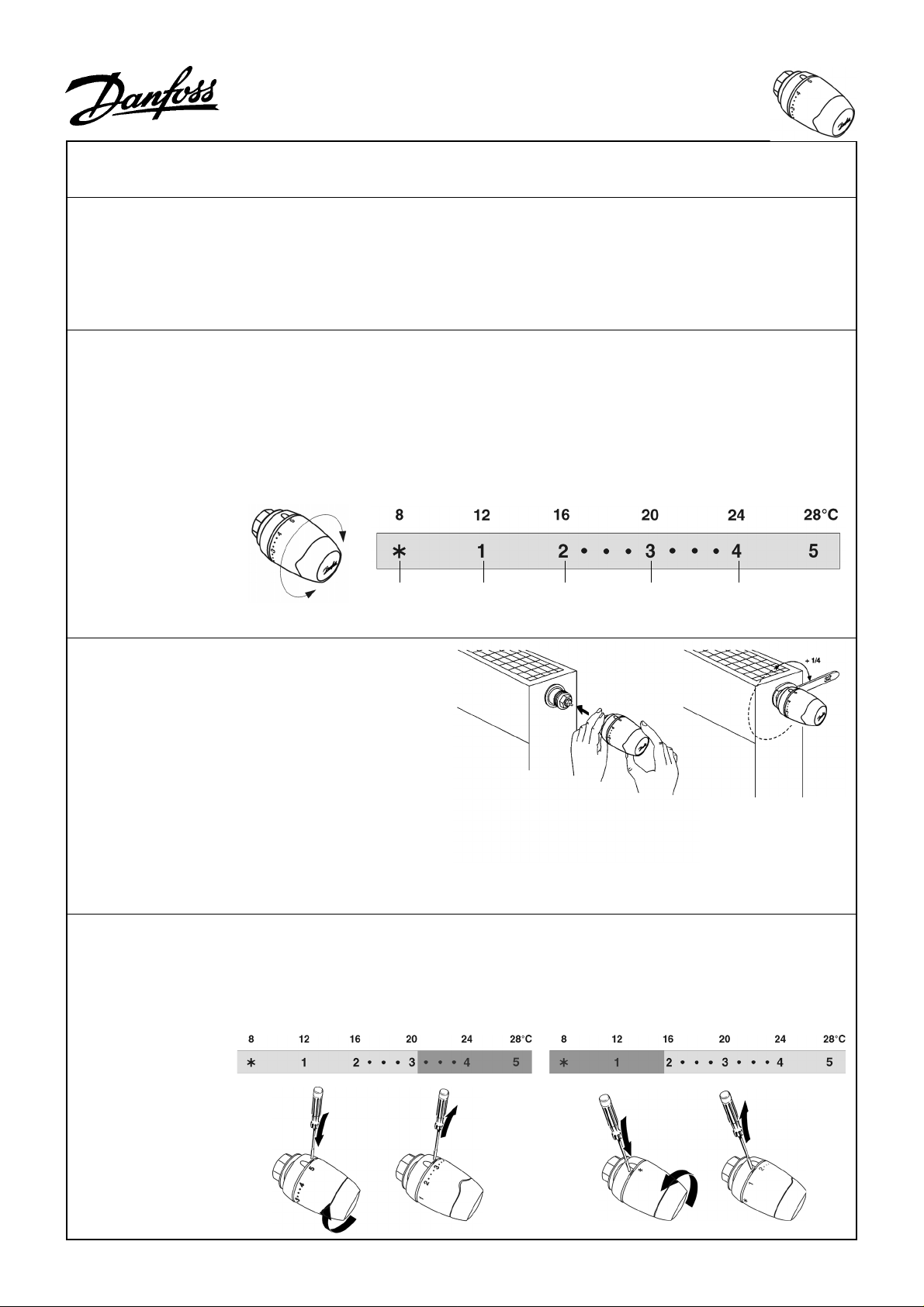
Setting the
temperature
Thermostatic sensor type RTS-K EverisTM 4250 and
4270 can be fitted without adapter on valve radiators
The thermostatic sensor with a liquid-filled bellows
system provides proportional regulation. The sensor
is actuated by ambient temperature. The calibrated
pressure in the bellows corresponds to the temperature of the charge. This pressure is balanced by the
force of a regulating spring.
On a rise in ambient temperature the liquid pressure
The required room temperature is set by turning the
setting dial. The temperature scales show the
correlation between scale values and the room
temperature. The temperature values stated are for
guidance only as the obtained room temperature will
often be influenced by installation conditions.
Room
temporarily
not in use
Cellar Corridor,
(compact radiators) from the manufacturers:
Diatherm, Kermi, Korado, Purmo, Rettig, Radson.
rises in the bellows, moving the valve cone towards
the closed position until equilibrium exists between
the bellows and the spring.
On a drop in ambient temperature the liquid
pressure falls, allowing the bellows to contract and
the valve cone to move towards the open position
until a state of equilibrium is re-established.
The temperature scales are stated according to
European standards at Xp = 2 °C. This means that
the radiator thermostats close at a sensor
temperature which is 2 °C higher than stated on the
temperature scales.
Different temperatures are recommended depending
on the purpose of the room. The illustration shows
the most frequently used.
bedroom
Living room,
kitchen
Bath room
013R9391
Mounting
Adjusting
temperature
control range
The sensor is supplied to connect
valves with M 30 x 1.5 connection.
During mounting the setting dial
should be in position 5.
The nut should be tightened with an
open-end 32 mm spanner.
Setting the upper limit
e.g. 3 as the highest possible temperature selection:
1. Turn the handle to max. position.
2. Keep the limiter tab to the right of the scale pointer
pressed down with a small screwdriver.
3. Turn the handle to 3 on scale and release the tab.
2)1)
Setting the lower limit
e.g. 2 as the lowest possible temperature selection:
1. Turn the head to. min. position.
2. Keep the limiter tab to the left of the scale pointer
pressed down with a small screwdriver.
3. Turn the head to 2 and release the tab.
DKCD VIVFK102 03/2004
 Loading...