

Page 1
Data sheet
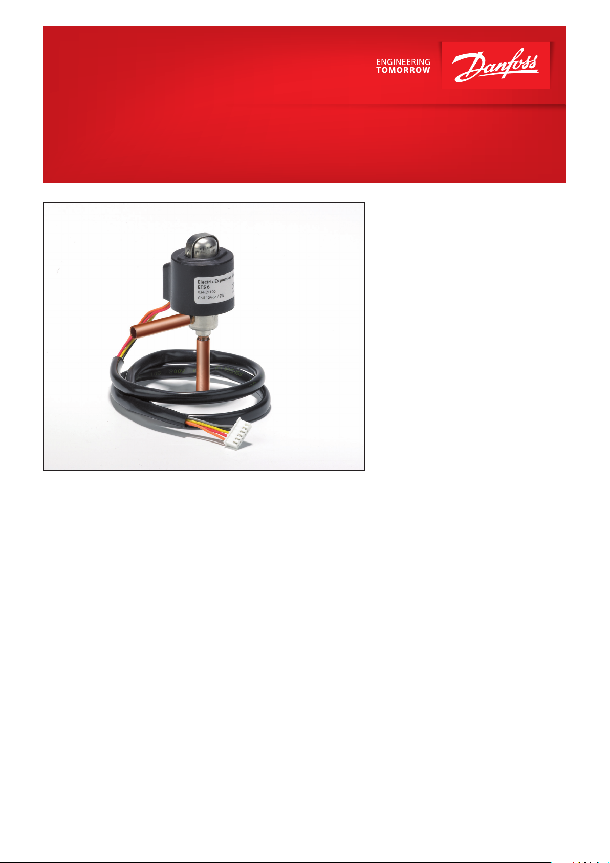
Electric expansion valves
Type ETS 6
The range of Electric expansion valves are based
on many years of experience.
ETS 6 secure reliability and provide a precise
solutions for ex pansion and flow control in a
wide range of refrigeration and air conditioning
systems.
Compact and lightweight. The current range is
available with a wide capacity range, and can be
used with all common fluorinated refrigerants.
Bi-flow operation is also possible for heat pump
systems.
The valve operation is by means of a uni-polar
motor, which can be controlled by a number of
controllers from Danfoss or third party vendors.
With an EKE 1V and EIM 336 (current drivers) and
an AKS sensor, an accuracy better than
± 0.5 K can be obtained.
Please contact Danfoss for more details.
Features • Optimized energy efficiency of the system.
• Precision flow control with high resolution.
• Compact and lightweight.
• Energy saving design.
• Proven know-how and high reliability.
• Wide range for all common refrigerants.
• Bi-flow for heat pump applications.
© Danfoss | DCS (rm) | 2019.08
AI227986437323en-000901 | 1
Page 2
Data sheet | Electric expansion valves, type ETS 6
Approvals
Technical data
Complies with:
EC PED 97/23/EC a3P3, RoHS, REACH
UL (Danfoss UL file no. is MH 7648.) and CQC
Valve data
Flow characteristic Bi-flow.
Maximum working pressure 47 bar / 681 psig.
Compatible refrigerants
Refrigerant oil All mineral oils and ester oils (to lubricate ETS 6 valve).
Ambient temperature
Fluid Temperature
(measured at the inlet of the
valve like the image below)
Durability
Ambient humidity 95 % RH or less.
Capacity control range 10 % – 100 %
Electrical data
Modulation Permanent magnet type direct operating stepper motor.
Excitation method 1-2 phase.
Electrical connection JST XHP-6, JST XHP-5 and AMP connection.
Excitation speed min. 30 pps (pulses per second) to max. 90 pps, recommended 31 pps.
Operating range
Full motion transit time e.g. 16 sec @ 30 pps, 6 sec @ 80 pps
Installation position
Liquid line solenoid valve
Max. coil winding temperature 115 °C / 239 ° F
Compatible Danfoss controller EKE 1A, EKE 1B, EKE 1C, EIM 336 (for OEM only).
RoHS
R22, R32, R134a, R290, R404A, R407C, R407H, R410A, R448, R449A, R452A,
R452B, R454C, R463A, R513A, R1234yf (for flammable refrigerants follow EN 378
standard)
-30 – 70°C / -22 – 158 °F
-30 – 70°C / -22 – 158 °F
Tested for 60 Million total pulses supplies to the valve during partially open
valve, which is comparable to 150,000 cycles if the valve is operated between
100 to 300 pulses open.
Tested for 30,000 full stroke cycles including 20 pulse overdrive at each closing.
0 to 480 pulses, no holding power required (NOTE: do not apply more than
520 pulses).
With coil on the upper side and the valve/coil assembly within ±15˚of the
vertical axis
If using a liquid line solenoid valve, it must be installed in such a way that it
does not create liquid hammering this ETS 6 valve.
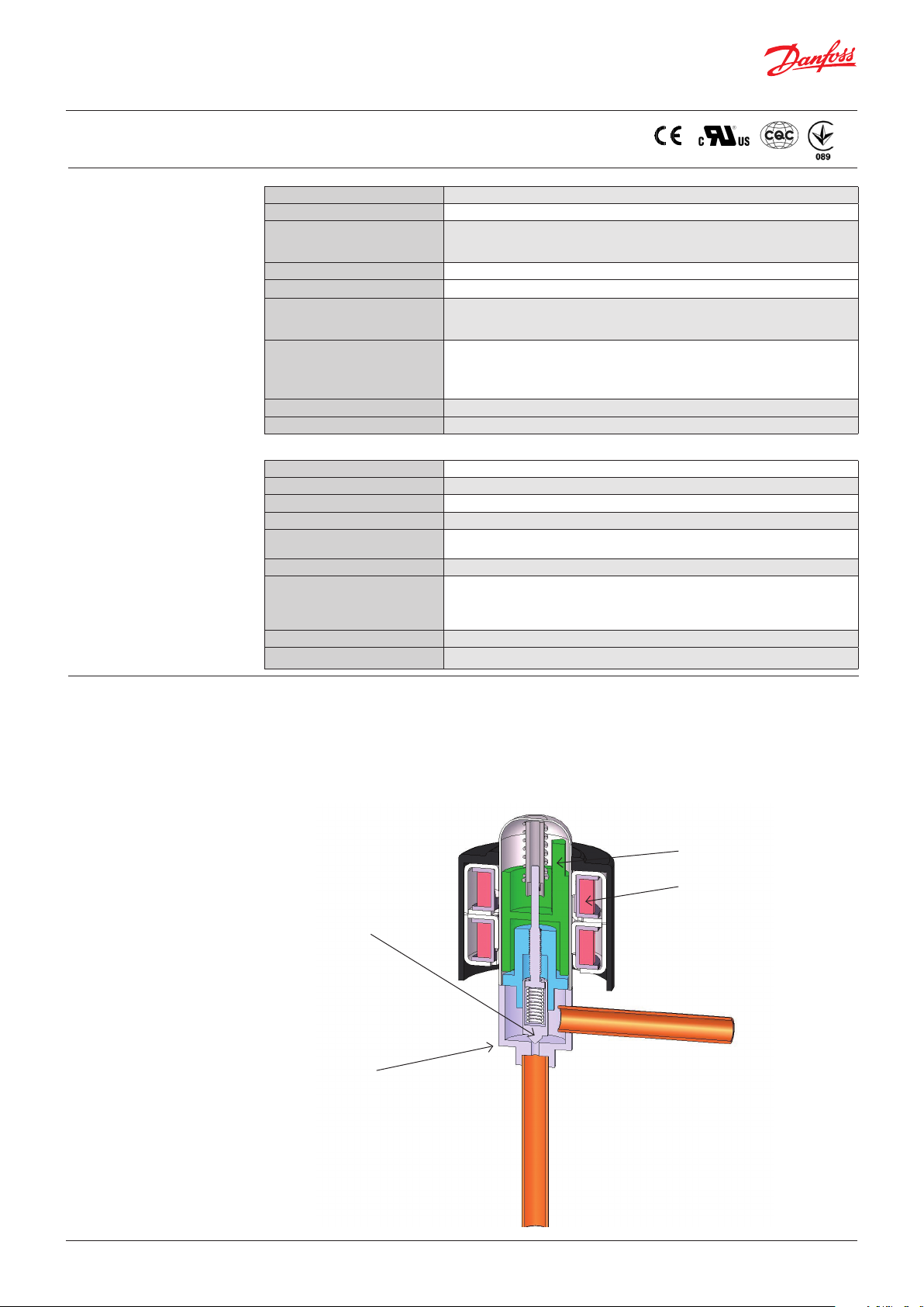
Design/function
The ETS 6 Electric expansion valves open and
close to regulate refrigerant flow by means of
a screw, whose rotating motion is transformed
into linear motion. This occurs by the rotation
of a magnet-needle valve assembly which
moves when electrical signals are applied to the
surrounding coil.
Within the coil structure, there are different
winding configurations, and the
Needle valve
Valve body
polarities are changed by the electrical signals
applied. By application of the appropriate
combination of signals, in the form of pulses,
the coil forces the rotor of the valve to move in a
stepwise fashion.
Application of multiple pulses will make the valve
mechanism to move through a series of steps
in the chosen direction, in order to set the valve
with the required opening degree.
Permanent magnet motor
Coil
Inlet (B*)
Outlet (A*)
© Danfoss | DCS (rm) | 2019.08
Bi-flow
Cross section diagram of ETS 6 series
* Refers to refrigerant flow in cooling mode
AI227986437323en-000901 | 2
Page 3
Data sheet | Electric expansion valves, type ETS 6
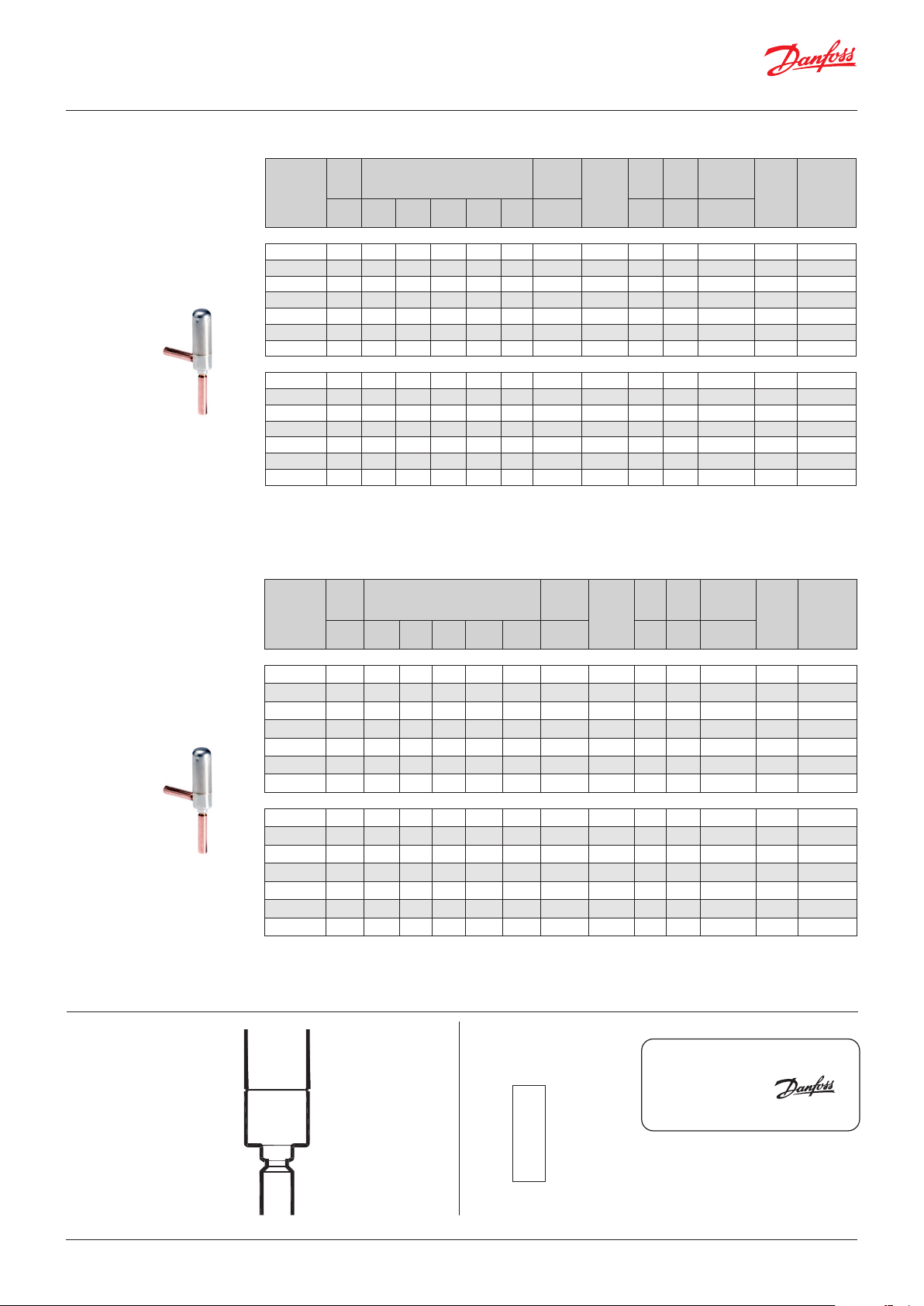
Valve ordering
Nominal Capacity kW
Orifice Nominal Capacity [kW]
Type
[mm] R22 R134a R404A R407C R410A
Connec-
tion
(solder)
A / B
[mm]
Valve
tube
confi-
guration
MWP MOPD
Reverse
Pressure
[bar] [bar] [bar]
Max.
1)
KV
[m3/h]
SI units
Code No.
Single pack
ETS 6 - 08 0.8 1.5 1.2 1.1 1.6 1.8 6.35 90° 47 35 20 0.011 034G5095
ETS 6 - 10 1 2.6 2 1.8 2.7 3.1 7.94 90° 47 35 35 0.030 034G5005
ETS 6 - 14 1.4 5.8 4.5 4.1 5.9 6.8 7.94 90° 47 35 20 0.052 034G5015
ETS 6 - 18 2) 1.8 10.3 8.1 7.3 10.6 12.1 6.35 90° 47 35 28 0.082 034G5026
ETS 6 - 25 2.5 19.6 15.3 13.8 20.1 23 7.94 90° 47 35 22 0.164 034G5035
ETS 6 - 32 3.2 28.8 22.5 20.3 29.6 33.9 7.94 90° 47 28 12* 0.242 034G5055
ETS 6 - 40 4 39.1 30.6 27.6 40.2 46 7.94 90° 47 21 7 0.329 034G5065
I-pack (100 units per box)
ETS 6 - 08 0.8 1.5 1.2 1.1 1.6 1.8 6.35 90° 47 35 20 0.011 034G5090
ETS 6 - 10 1 2.6 2 1.8 2.7 3.1 7.94 90° 47 35 35 0.030 034G5000
ETS 6 - 14 1.4 5.8 4.5 4.1 5.9 6.8 7.94 90° 47 35 20 0.052 034G5010
ETS 6 - 18 2) 1.8 10.3 8.1 7.3 10.6 12.1 6.35 90° 47 35 28 0.082 034G5024
ETS 6 - 25 2.5 19.6 15.3 13.8 20.1 23 7.94 90° 47 35 22 0.164 034G5030
ETS 6 - 32 3.2 28.8 22.5 20.3 29.6 33.9 7.94 90° 47 28 12* 0.242 034G5050
ETS 6 - 40 4 39.1 30.6 27.6 40.2 46 7.94 90° 47 21 7 0.329 034G5060
Nominal Capacity based on:
tC = 38 °C, te = 5 °C, SC = 0 °C, SH = 0 °C
* Please contact Danfoss if higher maximum reverse pressure valve is required.
1)
Max. Reverse Pressure = Pressure as which the valve can still close tightly in reverse direction (from A to B see fig. 1).
2
) For other connection size, please contact Danfoss.
Nominal Capacity [TR]
Orifice Nominal Capacity [TR]
Type
[in.] R22 R134a R404A R407C R410A
Connec-
tion
(solder)
A / B
[in.]
Valve
tube
confi-
guration
MWP MOPD
Reverse
Pressure
[psi] [psi] [psi]
Max.
1)
C
V
[gpm]
US units
Code No.
Single pack
ETS 6 - 08
ETS 6 - 10
ETS 6 - 14
ETS 6 - 18 2)
ETS 6 - 25
ETS 6 - 32
ETS 6 - 40
1
0.426 0.341 0.312 0.454 0.511
32
0
/
3
0.739 0.568 0.512 0.767 0.881
64
0
/
1
1.649 1.279 1.165 1.677 1.933
16
0
/
5
2.928 2.303 2.075 3.014 3.440
64
0
/
3
5.573 4.350 3.923 5.715 6.539
32
0
/
1
8.189 6.397 5.772 8.416 9.639
8
0
/
5
11.117 8.700 7.847 11.430 13.079
32
0
/
1
90° 681 507 290 0.013 034G5095
4
/
5
5
5
5
5
90° 681 507 507 0.035 034G5005
16
/
90° 681 507 290 0.060 034G5015
16
/
1
90° 681 507 406 0.099 034G5026
4
/
90° 681 507 319 0.190 034G5035
16
/
90° 681 406 174 0.280 034G5055
16
/
90° 681 304 101 0.380 034G5065
16
/
I-pack (100 units per box)
ETS 6 - 08
ETS 6 - 10
ETS 6 - 14
ETS 6 - 18 2)
ETS 6 - 25
ETS 6 - 32
ETS 6 - 40
1
0.426 0.341 0.312 0.454 0.511
32
0
/
3
0.739 0.568 0.512 0.767 0.881
64
0
/
1
1.649 1.279 1.165 1.677 1.933
16
0
/
5
2.928 2.303 2.075 3.014 3.440
64
0
/
3
5.573 4.350 3.923 5.715 6.539
32
0
/
1
8.189 6.397 5.772 8.416 9.639
8
0
/
5
11.117 8.700 7.847 11.430 13.079
32
0
/
1
90° 681 507 290 0.013 034G5090
4
/
5
5
5
5
5
90° 681 507 507 0.035 034G5000
16
/
90° 681 507 290 0.060 034G5010
16
/
1
90° 681 507 406 0.099 034G5024
4
/
90° 681 507 319 0.190 034G5030
16
/
90° 681 406 174 0.280 034G5050
16
/
90° 681 304 101 0.380 034G5060
16
/
Nominal Capacity based on:
tC = 100 °F, te = 41 °F, SC = 32 °F, SH = 32 °F
* Please contact Danfoss if higher maximum reverse pressure valve is required.
1)
Max. Reverse Pressure = Pressure as which the valve can still close tightly in reverse direction (from A to B see fig. 1).
2
) For other connection size, please contact Danfoss.
Product identification
© Danfoss | DCS (rm) | 2019.08
034G5xxx
7061
Valve
Danfoss code no.
Manufactoring no.
Coil
Manufacturing
no.
7061
Electric Expansion Valve
ETS 6
034G5xxx
Coil 12VDC / 3W
Product designation
Type
Danfoss code no.
Technical data
Contry of origin
AI227986437323en-000901 | 3
Made in YYY
Page 4
Data sheet | Electric expansion valves, type ETS 6
1
2
3
Coil ordering
Accessories
Single pack
Model
No.
Voltage
(current)
Enclosure
Insulation Cable length
class [m] [in.]
Connector
Units per
box
Single pack
Code No.
0.7 27.5 JST XHP-6 1 034G5105
0.7 27.5 JST XHP-5 1 034G5115
ETS 6 Coil
12 V DC
(0.26A/phase)
IP 66
Class “E”
(UL Class 105
(A))
1.5 59.0 JST XHP 5
2.0 78.7 JST XHP 5
3.0 118.0 JST XHP 5
0.6 23.6 AMP UPC- 6
1
1
1
1
034G5145
034G5185
034G5135
034G5175
I-pack
0.7 27.5 JST XHP-6 100 034G5100
0.7 27.5 JST XHP-5 100 034G5110
1.5 59.0 JST XHP 5 100 034G5140
2.0 78.7 JST XHP 5 100 034G5180
3.0 118.0 JST XHP 5 40 034G5130
ETS 6 Coil
12 V DC
(0.26A/phase)
IP 66
Class “E”
(UL Class 105
(A))
3.0 118.0 JST XHP 6 40 034G5150
0.6 23.6 AMP UPC- 6 100 034G5170
For the Danfoss controller select a ETS 6 coil with JST XHP-5 connector.
Type Description Code no.
ETS 6 manual coil Manual coil for service 034G5199
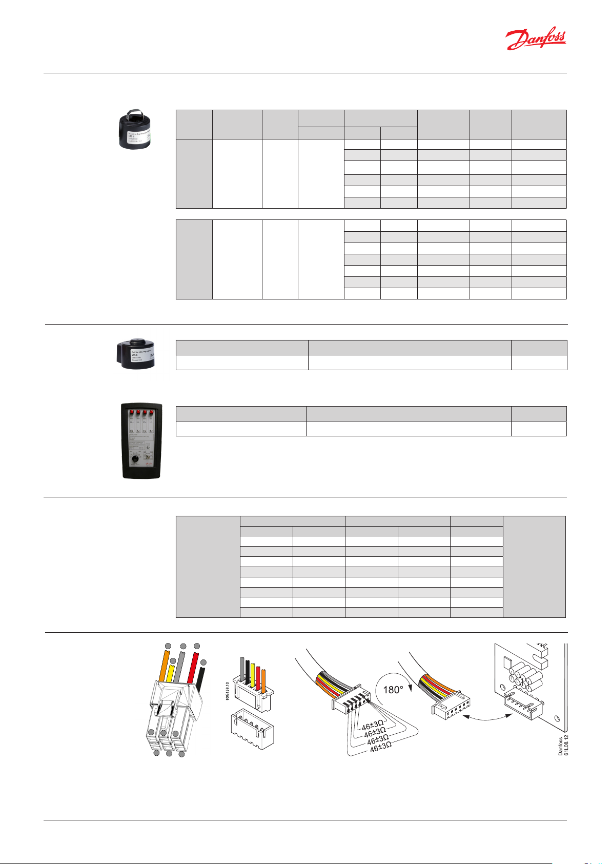
Stepper motor
switch sequence
Electrical wiring
Type Description Code no.
AST-G service driver Driver for service of the valve 034G0013
Coil I Coil II Common
Orange Yellow Red Black Gray
on off off off 0
on off on off 0
↓ OPENING ↓
off off on off 0
off on on off 0
↑ CLOSING ↑
off on off off 0
off on off on 0
off off off on 0
on off off on 0
4
6
© Danfoss | DCS (rm) | 2019.08
1
2
4
AMP UPC-6
Danfoss
80G322.10
3
5
6
JST XHP-5
JST XHP-6
Controller
The illustration shows the JST XHP-6 connetor. The coil with JST XHP-5 is identical except that it does not have an unused pin.
AI227986437323en-000901 | 4
Page 5
Data sheet | Electric expansion valves, type ETS 6
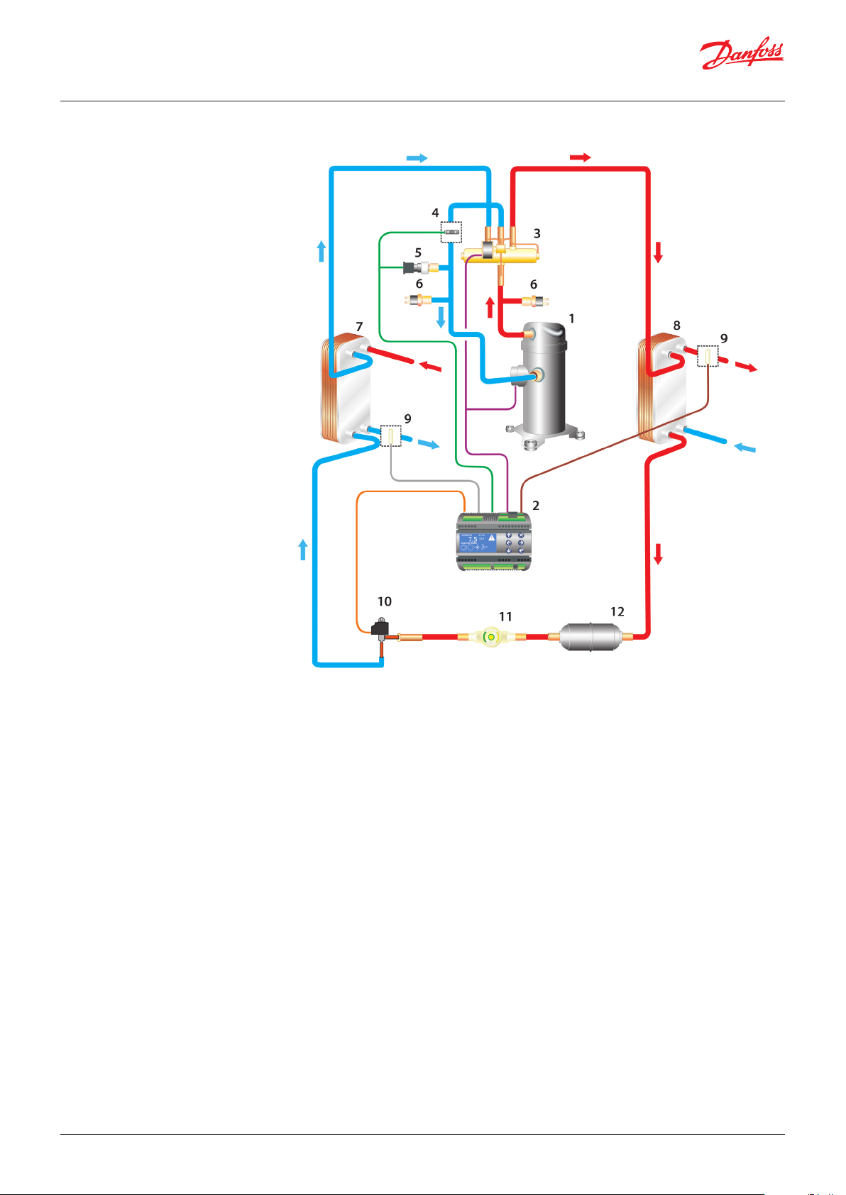
Application example
Heat pump components in typical system.
1. Compressor.
2. Controller.
3. Four-way valve.
4. Temperature sensor.
5. Pressure transmitter.
6. Cartridge pressure control.
7. Evaporator.
8. Condenser.
9. Temperature sensor.
10. Electric expansion valve.
11. Sight glass.
12. Liquid line filter drier.
© Danfoss | DCS (rm) | 2019.08
AI227986437323en-000901 | 5
Page 6
Data sheet | Electric expansion valves, type ETS 6
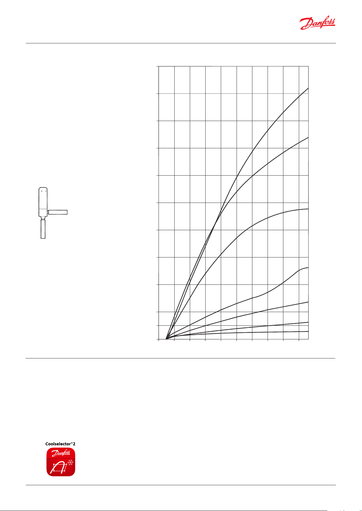
Pulse [PS]
Flow characteristics
Conditions R410 A
Te: 5 °C / 41 °F)
Tc: 38 °C / 100.4 °F)
Subcooling: 0 °C / 32 °F)
Superheat: 0 °C / 32 °F)
Flow B to A
B inlet
Refrigeration capacity in kW (TR)
50.0
(14.2)
45.0
(12.8)
40.0
(11.4)
35.0
(10.0)
30.0
(8.5)
25.0
(7.1)
20.0
(5.7)
Danfoss
34G165.10
ETS 6 - 40
ETS 6 - 32
ETS 6 - 25
A outlet
Valve Selection
15.0
(4.3)
ETS 6 - 18
10.0
(2.8)
ETS 6 - 14
5.0
(1.4)
2.5
(0.7)
0.0
050 100 150 200 250 300 350 400 450
ETS 6 - 10
ETS 6 - 08
Example
For optimum performance, it is important to
correct the evaporator capacity. In order to
select the correct size of ETS 6 you will need the
following information:
When selecting the valve it may be necessary to
apply a correction factor to the actual evaporator
capacity. This correction factor is required when
system conditions are different than table
conditions. Selection also depends on having an
Refrigerant: HCFC / HFC
Evaporator capacity Qe in kW or TR
Evaporating temperature te in °C / °F
Condenser temperature tc in °C / °F
Subcooling Δt
in K / °F
sub
acceptable pressure drop across the valve. In the
selection table, the pressure drop in the liquid
line is assumed to be zero. The following example
illustrates correct selection of the valve.
Refrigerant: R407C
Evaporator capacity: Qe = 10 kW / 2.84 TR
Condensing temperature: tc = 40 °C / 104 °F
Evaporating temperature: te = +10 °C / 50 °F
Subcooling Δt
= 10 K / 18 °F
sub
Note!
Coolselector®2 is a Danfoss calculation and selection software designed to make selection processes for all refrigeration
projects easier and less time consuming. For details refer http://coolselector.danfoss.com
© Danfoss | DCS (rm) | 2019.08
AI227986437323en-000901 | 6
Page 7
Data sheet | Electric expansion valves, type ETS 6
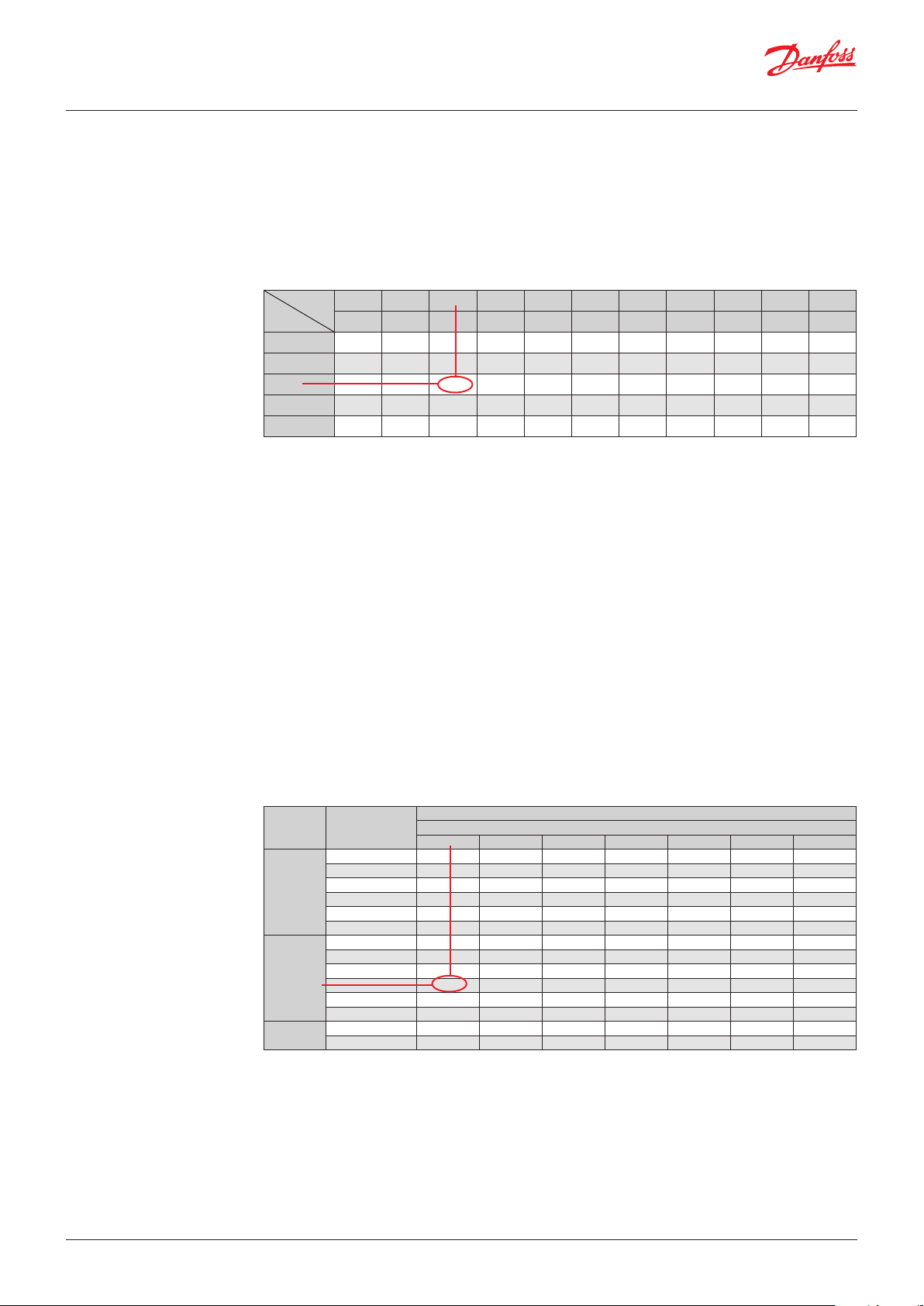
Valve Selection
(continued)
Step 1
Determine the correction factor for subcooling
Δt
. From the correction factor table (see below)
sub
a subcooling of 10 K, R407C corresponds to a
factor of 1.14.
Correction factors for subcooling Δt
R22 1.00 1.04 1.10 1.16 1.20 1.25 1.30 1.35 1.41 1.45 1.50
R410A 1.00 1.06 1.14 1.21 1.28 1.34 1.40 1.47 1.53 1.58 1.65
R407C 1.00 1.06 1.14 1.20 1.28 1.34 1.40 1.47 1.53 1.60 1.66
R134a 1.00 1.06 1.14 1.19 1.26 1.32 1.38 1.45 1.50 1.56 1.63
R404A 1.00 1.07 1.18 1.29 1.38 1.47 1.56 1.65 1.75 1.82 1.91
0°F 7.2°F 18°F 27°F 36°F 45°F 54°F 63°F 72°F 81°F 90°F
0K 4K 10K 15K 20K 25K 30K 35K 40K 45K 50K
ΔTsc
Step 2
Corrected evaporator capacity is
.
sub
Step 4
Choose ETS 6 -18:
• Single pack code no. 034G5026
Qe (Corrected) = 10 kW /1.14 = 8.8 kW / 2.5 TR
• I-pack code no. 034G5024
Step 3
Select the appropriate capacity table, R407C, and
choose the column for condensing temperature
of tc = 40°C / 104 °F and evaporating temperature
of te = 10°C / 50 °F which will provide an
equivalent or greater capacity of 8.8 kW / 2.5 TR.
ETS 6 - 18 provides 10.35 kW / 2.94 TR, which is
the proper selection for this example.
Rated Capacity (kW)
Condensing
temperature
(°C)
30 10.35 11.21 11.88 12.41 12.81 13.31 13.52
35 11.15 11.84 12.38 12.79 13.10 13.47 13.58
R410A
R407C
R22
38 11.51 12.11 12.58 12.94 13.20 13.50 13.55
40 11.70 12.25 12.67 13.00 13.23 13.48 13.50
45 12.00 12.44 12.77 13.02 13.19 13.33 13.27
50 12.07 12.41 12.66 12.84 12.95 13.00 12.86
30 8.95 9.61 10.11 10.48 10.74 11.02 11.06
35 9.75 10.26 10.65 10.92 11.11 11.27 11.22
38 10.13 10.57 10.90 11.13 11.28 11.38 11.28
40 10.35 10.75 11.04 11.24 11.36 11.42 11.30
45 10.79 11.09 11.30 11.43 11.50 11.47 11.27
50 11.06 11.28 11.42 11.49 11.50 11.39 11.13
30 8.59 9.27 9.80 10.22 10.53 10.92 11.07
35 9.41 9.96 10.38 10.71 10.96 11.24 11.33
Evaporation temperature (°C)
ETS 6 -18
10 5 0 -5 -10 -20 -30
© Danfoss | DCS (rm) | 2019.08
AI227986437323en-000901 | 7
Page 8

Data sheet | Electric expansion valves, type ETS 6
Correction factors for
subcooling Δt
sub
The evaporator capacities used must be
corrected if subcooling deviates from 0 K.
The corrected capacity can be obtained by
Δt
R22 1.00 1.04 1.10 1.16 1.20 1.25 1.30 1.35 1.41 1.45 1.50
R410A 1.00 1.06 1.14 1.21 1.28 1.34 1.40 1.47 1.53 1.58 1.65
R407C 1.00 1.06 1.14 1.20 1.28 1.34 1.40 1.47 1.53 1.60 1.66
R134a 1.00 1.06 1.14 1.19 1.26 1.32 1.38 1.45 1.50 1.56 1.63
R404A/R507 1.00 1.07 1.18 1.29 1.38 1.47 1.56 1.65 1.75 1.82 1.91
Δt
R32 1.00 1.03 1.08 1.12 1.16 1.20 1.23 1.27 1.31 1.34 1.37
R290 1.00 1.04 1.10 1.15 1.20 1.25 1.29 1.34 1.38 1.43 1.47
R448A 1.00 1.06 1.13 1.20 1.26 1.33 1.39 1.46 1.52 1.59 1.65
R449A 1.00 1.03 1.11 1.17 1.23 1.29 1.35 1.41 1.47 1.53 1.59
R452A 1.00 1.06 1.14 1.21 1.25 1.34 1.40 1.46 1.52 1.58 1.64
0K 4K 10K 15K 20K 25K 30K 35K 40K 45K 50K
sub
0°F 7.2°F 18°F 27°F 36°F 45°F 54°F 63°F 72°F 81°F 90°F
0K 4K 10K 15K 20K 25K 30K 35K 40K 45K 50K
sub
0°F 7.2°F 18°F 27°F 36°F 45°F 54°F 63°F 72°F 81°F 90°F
dividing the required evaporator capacity by the
correction factor below. Selections can then be
made from the tables above.
© Danfoss | DCS (rm) | 2019.08
AI227986437323en-000901 | 8
Page 9

Data sheet | Electric expansion valves, type ETS 6
Capacity (kW)
R22
R134a
R404A
R407C
R410A
Condensing
temperature
(°C)
30 1.27 1.37 1.45 1.51 1.56 1.62 1.64
35 1.39 1.47 1.54 1.59 1.62 1.66 1.68
38 1.45 1.52 1.58 1.62 1.65 1.69 1.69
40 1.49 1.55 1.61 1.64 1.67 1.70 1.70
45 1.56 1.62 1.66 1.69 1.71 1.72 1.72
50 1.62 1.66 1.69 1.72 1.73 1.73 1.72
30 1.01 1.08 1.13 1.16 1.19 1.20 1.20
35 1.10 1.15 1.19 1.22 1.23 1.23 1.22
38 1.15 1.19 1.22 1.24 1.25 1.25 1.22
40 1.17 1.21 1.24 1.25 1.26 1.25 1.23
45 1.23 1.26 1.27 1.28 1.28 1.26 1.22
50 1.27 1.28 1.29 1.29 1.28 1.26 1.21
30 0.95 1.01 1.06 1.10 1.12 1.14 1.12
35 1.01 1.06 1.10 1.12 1.13 1.13 1.11
38 1.03 1.07 1.10 1.12 1.13 1.12 1.09
40 1.04 1.08 1.10 1.11 1.12 1.11 1.07
45 1.05 1.08 1.09 1.09 1.09 1.07 1.02
50 1.04 1.05 1.05 1.05 1.04 1.01 0.96
30 1.32 1.42 1.50 1.55 1.59 1.63 1.64
35 1.44 1.52 1.58 1.62 1.64 1.67 1.66
38 1.50 1.56 1.61 1.65 1.67 1.68 1.67
40 1.53 1.59 1.63 1.66 1.68 1.69 1.67
45 1.60 1.64 1.67 1.69 1.70 1.70 1.67
50 1.64 1.67 1.69 1.70 1.70 1.69 1.65
30 1.53 1.66 1.76 1.84 1.90 1.97 2.00
35 1.65 1.75 1.83 1.89 1.94 1.99 2.01
38 1.70 1.79 1.86 1.91 1.95 2.00 2.01
40 1.73 1.81 1.88 1.92 1.96 2.00 2.00
45 1.78 1.84 1.89 1.93 1.95 1.97 1.96
50 1.79 1.84 1.87 1.90 1.92 1.92 1.90
10 5 0 -5 -10 -20 -30
Evaporation temperature [°C]
ETS 6 - 08
SI units
Capacity (kW)
R32
R290
R448A
R449A
R452A
Condensing
temperature
(°C)
30 2.19 2.39 2.54 2.67 2.77 2.91 2.99
35 2.40 2.56 2.69 2.79 2.88 2.99 3.05
38 2.49 2.64 2.76 2.85 2.93 3.03 3.08
40 2.55 2.69 2.80 2.88 2.95 3.05 3.10
45 2.66 2.78 2.87 2.94 3.00 3.08 3.11
50 2.74 2.83 2.91 2.97 3.02 3.08 3.10
30 1.36 1.45 1.53 1.58 1.62 1.66 1.66
35 1.47 1.54 1.60 1.64 1.66 1.68 1.67
38 1.52 1.59 1.63 1.66 1.68 1.69 1.67
40 1.55 1.61 1.65 1.68 1.69 1.69 1.67
45 1.61 1.65 1.68 1.69 1.70 1.69 1.65
50 1.65 1.67 1.69 1.70 1.69 1.66 1.61
30 1.37 1.48 1.50 1.59 1.56 1.58 1.58
35 1.47 1.56 1.56 1.64 1.60 1.61 1.58
38 1.48 1.56 1.56 1.63 1.60 1.59 1.57
40 1.50 1.57 1.57 1.63 1.60 1.59 1.56
45 1.53 1.59 1.58 1.63 1.59 1.57 1.53
50 1.53 1.58 1.56 1.61 1.56 1.53 1.48
30 1.35 1.42 1.47 1.51 1.54 1.56 1.55
35 1.42 1.48 1.52 1.55 1.56 1.57 1.55
38 1.46 1.50 1.54 1.56 1.57 1.57 1.54
40 1.47 1.52 1.54 1.56 1.57 1.56 1.53
45 1.50 1.53 1.55 1.56 1.56 1.54 1.50
50 1.51 1.53 1.54 1.54 1.53 1.50 1.46
30 1.06 1.12 1.15 1.18 1.20 1.20 1.18
35 1.11 1.15 1.18 1.19 1.20 1.19 1.16
38 1.13 1.16 1.18 1.19 1.19 1.17 1.14
40 1.13 1.16 1.18 1.18 1.18 1.16 1.12
45 1.14 1.15 1.16 1.16 1.15 1.12 1.07
50 1.11 1.12 1.12 1.11 1.10 1.06 1.00
10 5 0 -5 -10 -20 -30
Evaporation temperature [°C]
ETS 6 - 08
SI units
© Danfoss | DCS (rm) | 2019.08
AI227986437323en-000901 | 9
Page 10

Data sheet | Electric expansion valves, type ETS 6
Capacity (kW)
R22
R134a
R404A
R407C
R410A
Condensing
temperature
(°C)
30 2.15 2.32 2.45 2.55 2.63 2.73 2.77
35 2.35 2.49 2.60 2.68 2.74 2.81 2.83
38 2.45 2.58 2.67 2.74 2.79 2.85 2.86
40 2.52 2.63 2.71 2.78 2.82 2.87 2.88
45 2.64 2.73 2.80 2.85 2.88 2.91 2.90
50 2.74 2.81 2.86 2.90 2.92 2.93 2.90
30 1.71 1.82 1.91 1.97 2.01 2.04 2.02
35 1.86 1.95 2.01 2.05 2.08 2.09 2.05
38 1.94 2.01 2.06 2.09 2.11 2.11 2.07
40 1.98 2.05 2.09 2.12 2.13 2.12 2.07
45 2.08 2.12 2.15 2.16 2.16 2.13 2.07
50 2.14 2.17 2.18 2.18 2.17 2.12 2.05
30 1.60 1.71 1.80 1.85 1.89 1.92 1.90
35 1.71 1.79 1.85 1.89 1.91 1.91 1.88
38 1.75 1.82 1.86 1.89 1.90 1.89 1.84
40 1.76 1.82 1.86 1.88 1.89 1.87 1.81
45 1.78 1.82 1.84 1.85 1.84 1.80 1.73
50 1.75 1.77 1.78 1.77 1.76 1.70 1.61
30 2.24 2.40 2.53 2.62 2.69 2.76 2.76
35 2.44 2.57 2.66 2.73 2.78 2.82 2.81
38 2.53 2.64 2.72 2.78 2.82 2.84 2.82
40 2.59 2.69 2.76 2.81 2.84 2.86 2.82
45 2.70 2.77 2.82 2.86 2.87 2.87 2.82
50 2.77 2.82 2.85 2.87 2.88 2.85 2.78
30 2.59 2.80 2.97 3.10 3.20 3.33 3.38
35 2.79 2.96 3.09 3.20 3.28 3.37 3.39
38 2.88 3.03 3.14 3.23 3.30 3.37 3.39
40 2.92 3.06 3.17 3.25 3.31 3.37 3.37
45 3.00 3.11 3.19 3.25 3.30 3.33 3.32
50 3.02 3.10 3.17 3.21 3.24 3.25 3.21
10 5 0 -5 -10 -20 -30
Evaporation temperature [°C]
ETS 6 -10
SI units
Capacity (kW)
R32
R290
R448A
R449A
R452A
Condensing
temperature
(°C)
30 2.15 2.32 2.45 2.55 2.63 2.73 2.77
35 2.35 2.49 2.60 2.68 2.74 2.81 2.83
38 2.45 2.58 2.67 2.74 2.79 2.85 2.86
40 2.52 2.63 2.71 2.78 2.82 2.87 2.88
45 2.64 2.73 2.80 2.85 2.88 2.91 2.90
50 2.74 2.81 2.86 2.90 2.92 2.93 2.90
30 1.71 1.82 1.91 1.97 2.01 2.04 2.02
35 1.86 1.95 2.01 2.05 2.08 2.09 2.05
38 1.94 2.01 2.06 2.09 2.11 2.11 2.07
40 1.98 2.05 2.09 2.12 2.13 2.12 2.07
45 2.08 2.12 2.15 2.16 2.16 2.13 2.07
50 2.14 2.17 2.18 2.18 2.17 2.12 2.05
30 1.60 1.71 1.80 1.85 1.89 1.92 1.90
35 1.71 1.79 1.85 1.89 1.91 1.91 1.88
38 1.75 1.82 1.86 1.89 1.90 1.89 1.84
40 1.76 1.82 1.86 1.88 1.89 1.87 1.81
45 1.78 1.82 1.84 1.85 1.84 1.80 1.73
50 1.75 1.77 1.78 1.77 1.76 1.70 1.61
30 2.24 2.40 2.53 2.62 2.69 2.76 2.76
35 2.44 2.57 2.66 2.73 2.78 2.82 2.81
38 2.53 2.64 2.72 2.78 2.82 2.84 2.82
40 2.59 2.69 2.76 2.81 2.84 2.86 2.82
45 2.70 2.77 2.82 2.86 2.87 2.87 2.82
50 2.77 2.82 2.85 2.87 2.88 2.85 2.78
30 2.59 2.80 2.97 3.10 3.20 3.33 3.38
35 2.79 2.96 3.09 3.20 3.28 3.37 3.39
38 2.88 3.03 3.14 3.23 3.30 3.37 3.39
40 2.92 3.06 3.17 3.25 3.31 3.37 3.37
45 3.00 3.11 3.19 3.25 3.30 3.33 3.32
50 3.02 3.10 3.17 3.21 3.24 3.25 3.21
10 5 0 -5 -10 -20 -30
Evaporation temperature [°C]
ETS 6 -10
SI units
© Danfoss | DCS (rm) | 2019.08
AI227986437323en-000901 | 10
Page 11

Data sheet | Electric expansion valves, type ETS 6
Capacity (kW)
temperature (°C)
R22
R134a
R404A
R407C
R410A
Condensing
10 5 0 -5 -10 -20 -30
30 4.81 5.19 5.49 5.72 5.89 6.11 6.20
35 5.27 5.58 5.82 6.00 6.14 6.30 6.34
38 5.50 5.77 5.98 6.14 6.26 6.39 6.41
40 5.63 5.88 6.07 6.22 6.32 6.43 6.44
45 5.92 6.12 6.27 6.38 6.46 6.52 6.50
50 6.14 6.29 6.41 6.49 6.54 6.56 6.51
30 3.82 4.08 4.27 4.40 4.49 4.56 4.53
35 4.17 4.37 4.51 4.60 4.65 4.67 4.60
38 4.35 4.51 4.62 4.69 4.73 4.72 4.63
40 4.45 4.59 4.69 4.74 4.77 4.74 4.64
45 4.65 4.75 4.81 4.84 4.84 4.77 4.63
50 4.79 4.85 4.88 4.88 4.86 4.75 4.59
30 3.58 3.84 4.02 4.15 4.24 4.30 4.25
35 3.83 4.01 4.15 4.23 4.28 4.29 4.20
38 3.91 4.07 4.17 4.23 4.26 4.24 4.13
40 3.94 4.08 4.16 4.21 4.23 4.19 4.06
45 3.98 4.07 4.12 4.13 4.12 4.04 3.88
50 3.92 3.97 3.98 3.97 3.93 3.81 3.61
30 5.01 5.38 5.66 5.87 6.02 6.17 6.19
35 5.46 5.75 5.96 6.12 6.22 6.31 6.29
38 5.67 5.92 6.10 6.23 6.31 6.37 6.32
40 5.80 6.02 6.18 6.29 6.36 6.40 6.33
45 6.04 6.21 6.33 6.40 6.44 6.42 6.31
50 6.19 6.32 6.39 6.43 6.44 6.38 6.23
30 5.80 6.28 6.66 6.95 7.17 7.46 7.57
35 6.25 6.63 6.93 7.16 7.34 7.55 7.60
38 6.44 6.78 7.04 7.24 7.39 7.56 7.59
40 6.55 6.86 7.10 7.28 7.41 7.55 7.56
45 6.72 6.97 7.15 7.29 7.39 7.47 7.43
50 6.76 6.95 7.09 7.19 7.25 7.28 7.20
Evaporation temperature [°C]
ETS 6 - 14
SI units
Capacity (kW)
temperature (°C)
R32
R290
R448A
R449A
R452A
Condensing
10 5 0 -5 -10 -20 -30
30 8.30 9.04 9.63 10.10 10.48 11.02 11.32
35 9.06 9.67 10.16 10.56 10.88 11.32 11.56
38 9.44 9.98 10.43 10.78 11.07 11.46 11.66
40 9.65 10.16 10.58 10.91 11.18 11.54 11.71
45 10.08 10.51 10.86 11.14 11.36 11.65 11.77
50 10.36 10.72 11.02 11.25 11.43 11.65 11.72
30 5.13 5.50 5.78 5.98 6.13 6.27 6.27
35 5.56 5.84 6.05 6.20 6.30 6.37 6.31
38 5.76 6.00 6.18 6.29 6.36 6.40 6.31
40 5.88 6.09 6.24 6.34 6.40 6.40 6.30
45 6.10 6.25 6.36 6.41 6.43 6.38 6.23
50 6.23 6.34 6.39 6.41 6.40 6.29 6.10
30 5.19 5.61 5.67 6.02 5.91 5.99 5.96
35 5.56 5.89 5.90 6.19 6.06 6.08 6.00
38 5.60 5.91 5.91 6.17 6.04 6.03 5.94
40 5.67 5.96 5.94 6.18 6.04 6.02 5.91
45 5.80 6.02 5.97 6.16 6.00 5.93 5.78
50 5.80 5.98 5.91 6.07 5.90 5.80 5.62
30 5.11 5.38 5.58 5.73 5.82 5.90 5.87
35 5.39 5.60 5.75 5.86 5.92 5.94 5.87
38 5.52 5.69 5.82 5.90 5.94 5.94 5.84
40 5.58 5.74 5.84 5.91 5.94 5.92 5.81
45 5.68 5.80 5.86 5.90 5.90 5.84 5.69
50 5.70 5.77 5.81 5.82 5.80 5.69 5.51
30 4.01 4.22 4.37 4.47 4.52 4.54 4.46
35 4.20 4.35 4.45 4.51 4.53 4.50 4.38
38 4.26 4.38 4.46 4.50 4.51 4.44 4.30
40 4.29 4.39 4.45 4.48 4.48 4.40 4.24
45 4.30 4.36 4.39 4.38 4.35 4.23 4.04
50 4.22 4.24 4.24 4.21 4.16 4.00 3.78
Evaporation temperature [°C]
ETS 6 - 14
SI units
© Danfoss | DCS (rm) | 2019.08
AI227986437323en-000901 | 11
Page 12

Data sheet | Electric expansion valves, type ETS 6
Capacity (kW)
temperature (°C)
R22
R134a
R404A
R407C
R410A
Condensing
10 5 0 -5 -10 -20 -30
30 8.59 9.27 9.80 10.22 10.53 10.92 11.07
35 9.41 9.96 10.38 10.71 10.96 11.24 11.33
38 9.82 10.30 10.68 10.96 11.17 11.40 11.44
40 10.06 10.50 10.85 11.11 11.29 11.49 11.50
45 10.57 10.93 11.20 11.40 11.53 11.65 11.60
50 10.96 11.24 11.45 11.59 11.68 11.72 11.62
30 6.83 7.29 7.63 7.87 8.02 8.14 8.08
35 7.45 7.80 8.05 8.21 8.31 8.34 8.21
38 7.76 8.05 8.25 8.38 8.44 8.42 8.26
40 7.94 8.20 8.37 8.47 8.52 8.46 8.28
45 8.31 8.49 8.59 8.64 8.64 8.52 8.27
50 8.56 8.67 8.72 8.72 8.68 8.49 8.19
30 6.40 6.85 7.18 7.41 7.56 7.67 7.60
35 6.83 7.17 7.41 7.56 7.65 7.66 7.51
38 6.99 7.26 7.45 7.56 7.61 7.57 7.38
40 7.04 7.28 7.43 7.52 7.55 7.47 7.25
45 7.11 7.27 7.35 7.38 7.36 7.21 6.92
50 7.00 7.08 7.11 7.09 7.03 6.80 6.45
30 8.95 9.61 10.11 10.48 10.74 11.02 11.06
35 9.75 10.26 10.65 10.92 11.11 11.27 11.22
38 10.13 10.57 10.90 11.13 11.28 11.38 11.28
40 10.35 10.75 11.04 11.24 11.36 11.42 11.30
45 10.79 11.09 11.30 11.43 11.50 11.47 11.27
50 11.06 11.28 11.42 11.49 11.50 11.39 11.13
30 10.35 11.21 11.88 12.41 12.81 13.31 13.52
35 11.15 11.84 12.38 12.79 13.10 13.47 13.58
38 11.51 12.11 12.58 12.94 13.20 13.50 13.55
40 11.70 12.25 12.67 13.00 13.23 13.48 13.50
45 12.00 12.44 12.77 13.02 13.19 13.33 13.27
50 12.07 12.41 12.66 12.84 12.95 13.00 12.86
Evaporation temperature [°C]
ETS 6 -18
SI units
Capacity (kW)
temperature (°C)
R32
R290
R448A
R449A
R452A
Condensing
10 5 0 -5 -10 -20 -30
30 14.83 16.14 17.19 18.04 18.72 19.67 20.21
35 16.18 17.27 18.15 18.86 19.43 20.22 20.64
38 16.85 17.82 18.62 19.26 19.77 20.47 20.82
40 17.24 18.14 18.89 19.48 19.96 20.60 20.91
45 18.01 18.77 19.40 19.90 20.29 20.80 21.02
50 18.50 19.15 19.67 20.09 20.41 20.80 20.93
30 9.16 9.83 10.32 10.69 10.94 11.20 11.20
35 9.92 10.43 10.81 11.07 11.24 11.37 11.27
38 10.29 10.72 11.03 11.24 11.37 11.42 11.27
40 10.50 10.88 11.15 11.33 11.42 11.43 11.25
45 10.89 11.17 11.35 11.45 11.49 11.39 11.13
50 11.10 11.31 11.42 11.45 11.43 11.24 10.90
30 9.26 10.02 10.12 10.75 10.56 10.70 10.64
35 9.92 10.53 10.54 11.05 10.82 10.85 10.71
38 10.00 10.56 10.55 11.02 10.78 10.78 10.60
40 10.13 10.64 10.61 11.04 10.79 10.75 10.55
45 10.35 10.75 10.66 11.00 10.72 10.59 10.32
50 10.35 10.69 10.56 10.85 10.54 10.35 10.03
30 9.12 9.61 9.96 10.23 10.39 10.54 10.48
35 9.63 10.00 10.27 10.46 10.57 10.61 10.47
38 9.85 10.17 10.39 10.53 10.61 10.60 10.42
40 9.96 10.25 10.44 10.56 10.61 10.57 10.37
45 10.15 10.35 10.47 10.54 10.54 10.42 10.15
50 10.17 10.31 10.37 10.39 10.35 10.16 9.83
30 7.16 7.54 7.80 7.98 8.08 8.11 7.97
35 7.49 7.76 7.94 8.05 8.09 8.03 7.82
38 7.61 7.83 7.97 8.03 8.05 7.94 7.68
40 7.66 7.85 7.96 8.00 7.99 7.85 7.57
45 7.67 7.79 7.83 7.83 7.77 7.55 7.22
50 7.53 7.58 7.57 7.52 7.42 7.14 6.75
Evaporation temperature [°C]
ETS 6 -18
SI units
© Danfoss | DCS (rm) | 2019.08
AI227986437323en-000901 | 12
Page 13

Data sheet | Electric expansion valves, type ETS 6
Capacity (kW)
temperature (°C)
R22
R134a
R404A
R407C
R410A
Condensing
10 5 0 -5 -10 -20 -30
30 16.36 17.67 18.69 19.47 20.06 20.81 21.11
35 17.93 18.98 19.79 20.42 20.88 21.43 21.59
38 18.71 19.63 20.35 20.89 21.29 21.73 21.81
40 19.17 20.02 20.67 21.17 21.52 21.89 21.92
45 20.15 20.83 21.35 21.72 21.98 22.20 22.11
50 20.88 21.42 21.81 22.09 22.26 22.34 22.14
30 13.01 13.90 14.55 14.99 15.29 15.52 15.40
35 14.21 14.87 15.35 15.66 15.84 15.90 15.65
38 14.79 15.35 15.73 15.97 16.09 16.05 15.74
40 15.13 15.62 15.95 16.14 16.23 16.13 15.78
45 15.83 16.17 16.38 16.47 16.47 16.23 15.77
50 16.31 16.52 16.62 16.62 16.54 16.18 15.61
30 12.20 13.06 13.69 14.13 14.42 14.63 14.48
35 13.03 13.66 14.11 14.41 14.57 14.59 14.30
38 13.32 13.84 14.20 14.41 14.51 14.43 14.06
40 13.42 13.87 14.17 14.33 14.39 14.24 13.82
45 13.55 13.85 14.01 14.07 14.04 13.74 13.19
50 13.33 13.50 13.55 13.51 13.39 12.95 12.30
30 17.05 18.32 19.28 19.98 20.48 21.01 21.07
35 18.58 19.56 20.29 20.82 21.18 21.49 21.39
38 19.31 20.15 20.77 21.21 21.49 21.69 21.50
40 19.73 20.49 21.04 21.42 21.66 21.78 21.54
45 20.57 21.14 21.54 21.79 21.91 21.86 21.48
50 21.08 21.50 21.76 21.90 21.93 21.71 21.21
30 19.73 21.37 22.65 23.64 24.41 25.37 25.76
35 21.26 22.56 23.59 24.38 24.97 25.68 25.88
38 21.93 23.08 23.97 24.65 25.16 25.72 25.82
40 22.29 23.34 24.15 24.77 25.22 25.70 25.73
45 22.88 23.71 24.35 24.81 25.13 25.41 25.28
50 23.00 23.65 24.13 24.47 24.68 24.77 24.50
Evaporation temperature [°C]
ETS 6 - 25
SI units
Capacity (kW)
temperature (°C)
R32
R290
R448A
R449A
R452A
Condensing
10 5 0 -5 -10 -20 -30
30 28.26 30.75 32.76 34.38 35.67 37.50 38.53
35 30.84 32.90 34.59 35.95 37.03 38.54 39.34
38 32.11 33.97 35.48 36.70 37.68 39.01 39.69
40 32.85 34.58 35.99 37.13 38.04 39.26 39.86
45 34.32 35.78 36.97 37.92 38.67 39.64 40.05
50 35.27 36.50 37.49 38.28 38.89 39.64 39.89
30 17.40 18.67 19.62 20.31 20.79 21.27 21.27
35 18.85 19.82 20.53 21.03 21.36 21.60 21.41
38 19.55 20.37 20.95 21.35 21.60 21.70 21.42
40 19.94 20.67 21.18 21.52 21.71 21.73 21.38
45 20.70 21.22 21.57 21.76 21.83 21.65 21.14
50 21.15 21.50 21.69 21.76 21.72 21.36 20.71
30 17.65 19.11 19.28 20.48 20.12 20.40 20.29
35 18.91 20.26 20.09 21.06 20.62 20.68 20.41
38 19.06 20.12 20.11 21.00 20.54 20.54 20.20
40 19.30 20.28 20.22 21.05 20.57 20.49 20.11
45 19.73 20.49 20.32 20.97 20.43 20.18 19.66
50 19.73 20.37 20.13 20.67 20.09 19.73 19.11
30 17.38 18.31 18.99 19.49 19.81 20.09 19.96
35 18.35 19.07 19.58 19.93 20.14 20.23 19.96
38 18.77 19.38 19.79 20.08 20.22 20.20 19.86
40 18.99 19.53 19.89 20.13 20.23 20.15 19.76
45 19.34 19.73 19.96 20.09 20.09 19.86 19.35
50 19.39 19.65 19.77 19.80 19.73 19.36 18.74
30 13.65 14.36 14.87 15.20 15.39 15.45 15.18
35 14.28 14.79 15.14 15.34 15.42 15.31 14.90
38 14.51 14.92 15.18 15.31 15.34 15.12 14.64
40 14.60 14.95 15.16 15.25 15.23 14.96 14.43
45 14.63 14.84 14.93 14.92 14.82 14.40 13.76
50 14.35 14.44 14.43 14.33 14.15 13.60 12.86
Evaporation temperature [°C]
ETS 6 - 25
SI units
© Danfoss | DCS (rm) | 2019.08
AI227986437323en-000901 | 13
Page 14

Data sheet | Electric expansion valves, type ETS 6
Capacity (kW)
temperature (°C)
R22
R134a
R404A
R407C
R410A
Condensing
10 5 0 -5 -10 -20 -30
30 24.0 26.0 27.5 28.6 29.5 30.6 31.0
35 26.3 27.9 29.1 30.0 30.7 31.5 31.7
38 27.5 28.8 29.9 30.7 31.3 31.9 32.0
40 28.2 29.4 30.4 31.1 31.6 32.2 32.2
45 29.6 30.6 31.4 31.9 32.3 32.6 32.5
50 30.7 31.5 32.0 32.5 32.7 32.8 32.5
30 19.1 20.4 21.4 22.0 22.5 22.8 22.6
35 20.9 21.9 22.5 23.0 23.3 23.4 23.0
38 21.7 22.5 23.1 23.5 23.6 23.6 23.1
40 22.2 22.9 23.4 23.7 23.8 23.7 23.2
45 23.3 23.8 24.1 24.2 24.2 23.8 23.2
50 24.0 24.3 24.4 24.4 24.3 23.8 22.9
30 17.9 19.2 20.1 20.8 21.2 21.5 21.3
35 19.1 20.1 20.7 21.2 21.4 21.4 21.0
38 19.6 20.3 20.9 21.2 21.3 21.2 20.7
40 19.7 20.4 20.8 21.1 21.1 20.9 20.3
45 19.9 20.3 20.6 20.7 20.6 20.2 19.4
50 19.6 19.8 19.9 19.8 19.7 19.0 18.1
30 25.0 26.9 28.3 29.3 30.0 30.8 30.9
35 27.3 28.7 29.8 30.5 31.1 31.5 31.4
38 28.3 29.6 30.5 31.1 31.5 31.8 31.5
40 28.9 30.1 30.9 31.4 31.8 31.9 31.6
45 30.2 31.0 31.6 32.0 32.1 32.1 31.5
50 30.9 31.5 31.9 32.1 32.2 31.8 31.1
30 29.0 31.4 33.3 34.7 35.9 37.3 37.8
35 31.2 33.1 34.7 35.8 36.7 37.7 38.0
38 32.2 33.9 35.2 36.2 37.0 37.8 37.9
40 32.8 34.3 35.5 36.4 37.1 37.8 37.8
45 33.6 34.8 35.8 36.5 36.9 37.3 37.1
50 33.8 34.7 35.5 35.9 36.3 36.4 36.0
Evaporation temperature [°C]
ETS 6 - 32
SI units
Capacity (kW)
temperature (°C)
R32
R290
R448A
R449A
R452A
Condensing
10 5 0 -5 -10 -20 -30
30 41.52 45.18 48.13 50.50 52.41 55.09 56.60
35 45.32 48.35 50.82 52.81 54.40 56.62 57.79
38 47.18 49.91 52.13 53.92 55.36 57.31 58.30
40 48.26 50.80 52.88 54.55 55.88 57.68 58.56
45 50.42 52.56 54.31 55.71 56.81 58.24 58.84
50 51.81 53.62 55.08 56.24 57.14 58.24 58.60
30 25.64 27.51 28.91 29.92 30.64 31.35 31.35
35 27.79 29.21 30.26 31.00 31.48 31.83 31.56
38 28.81 30.01 30.88 31.47 31.82 31.98 31.56
40 29.39 30.46 31.21 31.71 31.99 32.02 31.50
45 30.50 31.27 31.78 32.07 32.17 31.90 31.16
50 31.16 31.68 31.97 32.07 32.01 31.47 30.52
30 25.93 28.07 28.33 30.09 29.56 29.97 29.80
35 27.78 29.47 29.52 30.94 30.30 30.39 29.98
38 28.01 29.56 29.54 30.86 30.18 30.17 29.68
40 28.36 29.79 29.71 30.92 30.22 30.11 29.55
45 28.99 30.11 29.86 30.81 30.02 29.65 28.89
50 28.99 29.92 29.57 30.37 29.52 28.98 28.08
30 25.53 26.90 27.90 28.63 29.11 29.51 29.33
35 29.69 28.01 28.76 29.28 29.58 29.71 29.33
38 27.58 28.47 29.08 29.50 29.70 29.68 29.18
40 27.90 28.69 29.22 29.57 29.71 29.60 29.03
45 28.41 28.98 29.32 29.51 29.52 29.18 28.43
50 28.49 28.87 29.05 29.10 28.98 28.44 27.53
30 20.05 21.10 21.84 22.33 22.62 22.70 22.30
35 20.98 21.73 22.24 22.54 22.66 22.49 21.89
38 21.31 21.92 22.30 22.50 22.53 22.22 21.51
40 21.45 21.97 22.27 22.40 22.38 21.98 21.20
45 21.49 21.80 21.93 21.91 21.77 21.15 20.21
50 21.09 21.22 21.20 21.05 20.79 19.98 18.89
Evaporation temperature [°C]
ETS 6 - 32
SI units
© Danfoss | DCS (rm) | 2019.08
AI227986437323en-000901 | 14
Page 15

Data sheet | Electric expansion valves, type ETS 6
Capacity (kW)
temperature (°C)
R22
R134a
R404A
R410A
Condensing
10 5 0 -10 -20 -30 -40
30 32.6 35.2 37.3 40.0 41.5 42.1 42.0
35 35.7 37.8 39.5 41.6 42.7 43.0 42.8
38 37.3 39.1 40.6 42.4 43.3 43.5 43.1
40 38.2 39.9 41.2 42.9 43.7 43.7 43.2
45 40.2 41.5 42.6 43.8 44.3 44.1 43.4
50 41.6 42.7 43.5 44.4 44.5 44.1 43.3
30 25.9 27.7 29.0 30.5 30.9 30.7 35 28.3 29.7 30.6 31.6 31.7 31.2 38 29.5 30.6 31.4 32.1 32.0 31.4 40 30.2 31.1 31.8 32.4 32.2 31.5 45 31.6 32.2 32.7 32.8 32.4 31.4 50 32.5 32.9 33.1 33.0 32.3 31.1 30 24.3 26.0 27.3 28.7 29.2 28.9 28.1
35 26.0 27.2 28.1 29.1 29.1 28.5 27.5
38 26.6 27.6 28.3 28.9 28.8 28.0 26.9
40 26.8 27.7 28.2 28.7 28.4 27.6 26.3
45 27.0 27.6 27.9 28.0 27.4 26.3 24.9
50 26.6 26.9 27.0 26.7 25.8 24.5 22.9
30 39.3 42.6 45.2 48.7 50.6 51.4 51.3
35 42.4 45.0 47.0 49.8 51.2 51.6 51.2
38 43.7 46.0 47.8 50.2 51.3 51.5 51.0
40 44.5 46.5 48.2 50.3 51.2 51.3 50.7
45 45.6 47.3 48.5 50.1 50.7 50.4 49.6
50 45.9 47.2 48.1 49.2 49.4 48.9 47.8
Evaporation temperature [°C]
ETS 6 - 40
SI units
Capacity (kW)
temperature (°C)
R32
R290
R448A
R449A
R452A
Condensing
10 5 0 -10 -20 -30 -40
30 59.48 64.74 68.96 72.36 75.09 78.93 81.09
35 64.93 69.28 72.81 75.66 77.95 81.12 82.80
38 67.60 71.50 74.69 77.26 79.31 82.12 83.53
40 69.14 72.79 75.76 78.16 80.07 82.64 83.90
45 72.24 75.31 77.81 79.82 81.39 83.45 84.31
50 74.23 76.82 78.92 80.58 81.86 83.45 83.96
30 34.79 37.34 39.23 40.61 41.58 42.55 42.55
35 37.71 39.65 41.06 42.06 42.72 43.19 42.83
38 39.10 40.73 41.91 42.71 43.19 43.40 42.83
40 39.89 41.34 42.36 43.04 43.41 43.45 42.75
45 41.40 42.44 43.13 43.52 43.65 43.29 42.29
50 42.29 42.99 43.39 43.52 43.44 42.71 41.42
30 37.15 40.22 40.59 43.12 42.35 42.94 42.70
35 39.81 42.23 42.29 44.33 43.41 43.54 42.95
38 40.13 42.36 42.33 44.21 43.24 43.23 42.53
40 40.63 42.68 42.57 44.30 43.29 43.14 42.33
45 41.53 43.14 42.78 44.15 43.01 42.48 41.39
50 41.53 42.87 42.37 43.51 42.29 41.52 40.23
30 36.58 38.54 39.98 41.02 41.70 42.28 42.02
35 38.62 40.13 41.20 41.96 42.38 42.57 42.02
38 39.51 40.79 41.67 42.26 42.55 42.53 41.81
40 39.97 41.11 41.87 42.37 42.57 42.41 41.59
45 40.70 41.52 42.01 42.28 42.29 41.81 40.74
50 40.82 41.36 41.62 41.69 41.52 40.75 39.44
30 28.73 30.23 31.29 31.00 32.40 32.53 31.96
35 30.05 31.14 31.86 32.29 32.47 32.22 31.37
38 30.54 31.41 31.96 32.23 32.28 31.83 30.82
40 30.74 31.48 31.91 32.10 32.07 31.49 30.38
45 30.79 31.24 31.43 31.40 31.18 30.31 28.96
50 30.21 30.40 30.38 30.16 29.78 28.63 27.06
Evaporation temperature [°C]
ETS 6 - 40
SI units
© Danfoss | DCS (rm) | 2019.08
AI227986437323en-000901 | 15
Page 16

Data sheet | Electric expansion valves, type ETS 6
Capacity (TR)
R22
R134a
R404A
R407C
R410A
Condensing
temperature
(°F)
75 0.452 0.452 0.45 0.446 0.439 0.414 0.394 0.367 0.385 0.28
85 0.464 0.465 0.465 0.463 0.458 0.439 0.423 0.402 0.437 0.336
95 0.474 0.475 0.477 0.476 0.474 0.46 0.448 0.431 0.482 0.38
115 0.481 0.484 0.488 0.491 0.492 0.487 0.481 0.471 0.547 0.44
125 0.478 0.481 0.487 0.491 0.493 0.492 0.488 0.481 0.569 0.458
135 0.472 0.475 0.482 0.487 0.491 0.493 0.491 0.487 0.584 0.469
75 0.325 0.327 0.329 0.33 0.329 0.317 0.305 0.287 0.262 0.225
85 0.331 0.334 0.338 0.341 0.341 0.335 0.327 0.314 0.296 0.269
95 0.336 0.339 0.344 0.348 0.351 0.349 0.344 0.336 0.323 0.303
115 0.333 0.338 0.345 0.352 0.358 0.365 0.365 0.362 0.357 0.347
125 0.326 0.331 0.34 0.348 0.355 0.365 0.367 0.367 0.365 0.359
135 0.316 0.321 0.331 0.34 0.349 0.362 0.366 0.368 0.368 0.365
75 0.317 0.319 0.322 0.324 0.322 0.311 0.299 0.281 0.257 0.221
85 0.312 0.315 0.32 0.323 0.324 0.319 0.311 0.299 0.281 0.255
95 0.304 0.307 0.314 0.319 0.322 0.321 0.317 0.309 0.297 0.279
115 0.27 0.275 0.284 0.292 0.298 0.307 0.308 0.307 0.302 0.294
125 0.244 0.249 0.259 0.268 0.276 0.288 0.292 0.293 0.292 0.287
135 0.211 0.217 0.228 0.238 0.248 0.263 0.268 0.272 0.273 0.272
75 0.459 0.461 0.464 0.464 0.463 0.449 0.435 0.416 0.389 0.351
85 0.463 0.466 0.47 0.473 0.473 0.465 0.456 0.441 0.421 0.392
95 0.465 0.468 0.474 0.478 0.481 0.478 0.472 0.461 0.446 0.424
115 0.452 0.456 0.465 0.472 0.478 0.484 0.483 0.479 0.472 0.46
125 0.436 0.442 0.451 0.46 0.467 0.477 0.479 0.477 0.473 0.465
135 0.416 0.422 0.433 0.443 0.451 0.464 0.468 0.469 0.468 0.463
75 0.561 0.561 0.559 0.553 0.544 0.511 0.486 0.459 0.406 0.343
85 0.566 0.567 0.567 0.564 0.558 0.534 0.514 0.493 0.452 0.404
95 0.567 0.568 0.57 0.57 0.567 0.549 0.534 0.518 0.486 0.449
115 0.544 0.548 0.553 0.556 0.558 0.552 0.544 0.536 0.516 0.494
125 0.519 0.523 0.53 0.535 0.538 0.537 0.533 0.527 0.512 0.496
135 0.484 0.489 0.497 0.504 0.509 0.512 0.51 0.508 0.497 0.485
-40 -35 -25 -15 -5 15 25 35 45 55
Evaporation temperature [°F]
ETS 6 - 08
US units
Capacity (TR)
R32
R290
R448A
R449A
R452A
Condensing
temperature
(°F)
75 0.835 0.833 0.824 0.811 0.793 0.737 0.696 0.643 0.575 0.484
85 0.859 0.857 0.851 0.841 0.827 0.825 0.746 0.704 0.649 0.578
95 0.875 0.874 0.871 0.864 0.853 0.815 0.788 0.752 0.708 0.651
115 0.883 0.885 0.885 0.883 0.877 0.854 0.836 0.839 0.782 0.743
125 0.872 0.874 0.876 0.876 0.873 0.856 0.842 0.822 0.797 0.766
135 0.852 0.855 0.859 0.860 0.859 0.848 0.836 0.821 0.800 0.774
75 0.459 0.460 0.462 0.461 0.457 0.437 0.418 0.392 0.356 0.303
85 0.464 0.466 0.470 0.472 0.471 0.458 0.448 0.425 0.398 0.361
95 0.464 0.467 0.473 0.477 0.478 0.472 0.464 0.450 0.430 0.403
115 0.450 0.455 0.464 0.472 0.478 0.484 0.482 0.477 0.468 0.454
125 0.434 0.440 0.451 0.461 0.469 0.479 0.481 0.479 0.474 0.465
135 0.414 0.421 0.433 0.445 0.454 0.469 0.473 0.475 0.473 0.468
75 0.433 0.434 0.435 0.434 0.432 0.416 0.412 0.378 0.349 0.289
85 0.432 0.436 0.445 0.449 0.450 0.445 0.447 0.425 0.408 0.370
95 0.411 0.422 0.444 0.453 0.456 0.457 0.460 0.443 0.432 0.396
115 0.412 0.418 0.430 0.439 0.445 0.453 0.460 0.450 0.445 0.425
125 0.396 0.403 0.418 0.427 0.435 0.445 0.454 0.446 0.444 0.428
135 0.347 0.353 0.365 0.376 0.386 0.401 0.406 0.409 0.409 0.406
75 0.433 0.434 0.435 0.434 0.432 0.416 0.412 0.378 0.349 0.289
85 0.439 0.440 0.441 0.442 0.443 0.437 0.428 0.414 0.395 0.367
95 0.439 0.440 0.441 0.443 0.446 0.444 0.438 0.428 0.414 0.395
115 0.418 0.421 0.426 0.432 0.438 0.444 0.443 0.436 0.428 0.422
125 0.405 0.407 0.412 0.419 0.427 0.436 0.437 0.436 0.432 0.424
135 0.357 0.363 0.374 0.385 0.395 0.411 0.422 0.420 0.422 0.414
75 0.329 0.332 0.336 0.339 0.340 0.332 0.323 0.308 0.289 0.257
85 0.324 0.328 0.333 0.338 0.341 0.339 0.334 0.324 0.311 0.289
95 0.316 0.320 0.327 0.333 0.337 0.340 0.338 0.329 0.323 0.306
115 0.282 0.288 0.297 0.307 0.314 0.325 0.328 0.328 0.325 0.318
125 0.254 0.261 0.271 0.282 0.290 0.306 0.310 0.313 0.314 0.311
135 0.225 0.231 0.242 0.255 0.264 0.283 0.289 0.294 0.296 0.296
-40 -35 -25 -15 -5 15 25 35 45 55
Evaporation temperature [°F]
ETS 6 - 08
US units
© Danfoss | DCS (rm) | 2019.08
AI227986437323en-000901 | 16
Page 17

Data sheet | Electric expansion valves, type ETS 6
Capacity (TR)
temperature
R22
R134a
R404A
R407C
R410A
Condensing
(°F)
75 0.76 0.76 0.76 0.75 0.74 0.70 0.67 0.62 0.65 0.47
85 0.78 0.79 0.79 0.78 0.77 0.74 0.72 0.68 0.74 0.57
95 0.80 0.80 0.81 0.81 0.80 0.78 0.76 0.73 0.82 0.64
115 0.81 0.82 0.82 0.83 0.83 0.82 0.81 0.80 0.92 0.74
125 0.81 0.81 0.82 0.83 0.83 0.83 0.83 0.81 0.96 0.77
135 0.80 0.80 0.81 0.82 0.83 0.83 0.83 0.82 0.99 0.79
75 0.55 0.55 0.56 0.56 0.56 0.54 0.52 0.49 0.44 0.38
85 0.56 0.56 0.57 0.58 0.58 0.57 0.55 0.53 0.50 0.45
95 0.57 0.57 0.58 0.59 0.59 0.59 0.58 0.57 0.55 0.51
115 0.56 0.57 0.58 0.60 0.61 0.62 0.62 0.61 0.60 0.59
125 0.55 0.56 0.57 0.59 0.60 0.62 0.62 0.62 0.62 0.61
135 0.53 0.54 0.56 0.58 0.59 0.61 0.62 0.62 0.62 0.62
75 0.54 0.54 0.54 0.55 0.55 0.53 0.51 0.48 0.43 0.37
85 0.53 0.53 0.54 0.55 0.55 0.54 0.53 0.50 0.48 0.43
95 0.51 0.52 0.53 0.54 0.54 0.54 0.54 0.52 0.50 0.47
115 0.46 0.46 0.48 0.49 0.50 0.52 0.52 0.52 0.51 0.50
125 0.41 0.42 0.44 0.45 0.47 0.49 0.49 0.50 0.49 0.49
135 0.36 0.37 0.39 0.40 0.42 0.44 0.45 0.46 0.46 0.46
75 0.78 0.78 0.78 0.78 0.78 0.76 0.74 0.70 0.66 0.59
85 0.78 0.79 0.79 0.80 0.80 0.79 0.77 0.75 0.71 0.66
95 0.79 0.79 0.80 0.81 0.81 0.81 0.80 0.78 0.75 0.72
115 0.76 0.77 0.79 0.80 0.81 0.82 0.82 0.81 0.80 0.78
125 0.74 0.75 0.76 0.78 0.79 0.81 0.81 0.81 0.80 0.79
135 0.70 0.71 0.73 0.75 0.76 0.78 0.79 0.79 0.79 0.78
75 0.95 0.95 0.94 0.94 0.92 0.86 0.82 0.78 0.69 0.58
85 0.96 0.96 0.96 0.95 0.94 0.90 0.87 0.83 0.76 0.68
95 0.96 0.96 0.96 0.96 0.96 0.93 0.90 0.88 0.82 0.76
115 0.92 0.93 0.93 0.94 0.94 0.93 0.92 0.91 0.87 0.84
125 0.88 0.88 0.89 0.90 0.91 0.91 0.90 0.89 0.87 0.84
135 0.82 0.83 0.84 0.85 0.86 0.87 0.86 0.86 0.84 0.82
-40 -35 -25 -15 -5 15 25 35 45 55
Evaporation temperature [°F]
ETS 6 -10
US units
Capacity (TR)
temperature
R32
R290
R448A
449A
R152A
Condensing
(°F)
75 1.411 1.406 1.392 1.370 1.340 1.244 1.176 1.086 0.972 0.817
85 1.451 1.448 1.438 1.421 1.397 1.394 1.260 1.189 1.095 0.976
95 1.477 1.476 1.471 1.459 1.440 1.377 1.331 1.271 1.196 1.100
115 1.492 1.494 1.495 1.491 1.482 1.443 1.413 1.417 1.321 1.256
125 1.473 1.476 1.480 1.480 1.475 1.446 1.422 1.389 1.347 1.293
135 1.439 1.444 1.450 1.453 1.451 1.432 1.413 1.386 1.352 1.308
75 0.775 0.777 0.780 0.779 0.772 0.737 0.706 0.662 0.601 0.512
85 0.783 0.788 0.794 0.797 0.795 0.773 0.757 0.718 0.673 0.609
95 0.783 0.789 0.799 0.806 0.808 0.798 0.784 0.760 0.727 0.680
115 0.760 0.768 0.784 0.798 0.808 0.817 0.814 0.806 0.790 0.766
125 0.734 0.744 0.762 0.778 0.792 0.809 0.812 0.809 0.801 0.785
135 0.700 0.711 0.732 0.751 0.768 0.793 0.799 0.802 0.800 0.791
75 0.731 0.733 0.736 0.734 0.729 0.703 0.696 0.639 0.590 0.488
85 0.730 0.737 0.752 0.758 0.761 0.752 0.754 0.717 0.689 0.626
95 0.695 0.713 0.750 0.765 0.771 0.771 0.778 0.749 0.729 0.669
115 0.695 0.706 0.727 0.741 0.752 0.765 0.777 0.760 0.752 0.718
125 0.669 0.681 0.706 0.722 0.734 0.752 0.767 0.754 0.749 0.722
135 0.587 0.597 0.617 0.635 0.651 0.677 0.685 0.690 0.691 0.686
75 0.731 0.733 0.736 0.734 0.729 0.703 0.696 0.639 0.590 0.488
85 0.742 0.743 0.744 0.747 0.749 0.738 0.723 0.700 0.668 0.621
95 0.742 0.742 0.744 0.749 0.754 0.750 0.741 0.724 0.700 0.668
115 0.707 0.711 0.719 0.729 0.740 0.749 0.748 0.737 0.722 0.712
125 0.683 0.688 0.696 0.708 0.721 0.736 0.739 0.737 0.730 0.717
135 0.603 0.613 0.632 0.650 0.667 0.694 0.713 0.709 0.712 0.700
75 0.556 0.561 0.568 0.573 0.574 0.560 0.546 0.520 0.488 0.434
85 0.547 0.554 0.563 0.572 0.576 0.573 0.565 0.548 0.526 0.488
95 0.533 0.541 0.552 0.563 0.570 0.575 0.571 0.555 0.545 0.517
115 0.477 0.486 0.501 0.518 0.530 0.550 0.553 0.553 0.549 0.538
125 0.429 0.440 0.457 0.476 0.490 0.517 0.524 0.529 0.530 0.525
135 0.379 0.391 0.409 0.430 0.446 0.478 0.488 0.496 0.500 0.500
-40 -35 -25 -15 -5 15 25 35 45 55
Evaporation temperature [°F]
ETS 6 -10
US units
© Danfoss | DCS (rm) | 2019.08
AI227986437323en-000901 | 17
Page 18

Data sheet | Electric expansion valves, type ETS 6
Capacity (TR)
R22
R134a
R404A
R407C
R410A
Condensing
temperature
(°F)
75 1.71 1.71 1.70 1.69 1.66 1.57 1.49 1.39 1.46 1.06
85 1.76 1.76 1.76 1.75 1.73 1.66 1.60 1.52 1.66 1.27
95 1.79 1.80 1.80 1.80 1.79 1.74 1.70 1.63 1.82 1.44
115 1.82 1.83 1.85 1.86 1.86 1.84 1.82 1.78 2.07 1.66
125 1.81 1.82 1.84 1.86 1.87 1.86 1.85 1.82 2.15 1.73
135 1.78 1.80 1.82 1.84 1.86 1.87 1.86 1.84 2.21 1.77
75 1.23 1.24 1.25 1.25 1.24 1.20 1.15 1.09 0.99 0.85
85 1.25 1.26 1.28 1.29 1.29 1.27 1.24 1.19 1.12 1.02
95 1.27 1.28 1.30 1.32 1.33 1.32 1.30 1.27 1.22 1.15
115 1.26 1.28 1.31 1.33 1.35 1.38 1.38 1.37 1.35 1.31
125 1.23 1.25 1.29 1.32 1.34 1.38 1.39 1.39 1.38 1.36
135 1.19 1.21 1.25 1.29 1.32 1.37 1.38 1.39 1.39 1.38
75 1.20 1.21 1.22 1.22 1.22 1.18 1.13 1.06 0.97 0.83
85 1.18 1.19 1.21 1.22 1.23 1.21 1.18 1.13 1.06 0.97
95 1.15 1.16 1.19 1.21 1.22 1.22 1.20 1.17 1.12 1.05
115 1.02 1.04 1.07 1.10 1.13 1.16 1.17 1.16 1.14 1.11
125 0.92 0.94 0.98 1.02 1.05 1.09 1.10 1.11 1.10 1.09
135 0.80 0.82 0.86 0.90 0.94 1.00 1.02 1.03 1.03 1.03
75 1.74 1.74 1.75 1.76 1.75 1.70 1.65 1.57 1.47 1.33
85 1.75 1.76 1.78 1.79 1.79 1.76 1.72 1.67 1.59 1.48
95 1.76 1.77 1.79 1.81 1.82 1.81 1.78 1.74 1.69 1.60
115 1.71 1.73 1.76 1.79 1.81 1.83 1.83 1.81 1.79 1.74
125 1.65 1.67 1.71 1.74 1.77 1.80 1.81 1.81 1.79 1.76
135 1.57 1.60 1.64 1.68 1.71 1.76 1.77 1.78 1.77 1.75
75 2.12 2.12 2.11 2.09 2.06 1.93 1.84 1.74 1.54 1.30
85 2.14 2.15 2.15 2.13 2.11 2.02 1.94 1.87 1.71 1.53
95 2.14 2.15 2.16 2.16 2.14 2.08 2.02 1.96 1.84 1.70
115 2.06 2.07 2.09 2.11 2.11 2.09 2.06 2.03 1.95 1.87
125 1.96 1.98 2.00 2.02 2.04 2.03 2.01 2.00 1.94 1.88
135 1.83 1.85 1.88 1.91 1.92 1.94 1.93 1.92 1.88 1.83
-40 -35 -25 -15 -5 15 25 35 45 55
Evaporation temperature [°F]
ETS 6 -14
US units
Capacity (TR)
temperature
R32
R290
R448A
R449A
R452A
Condensing
(°F)
75 3.161 3.150 3.119 3.070 3.002 2.788 2.634 2.433 2.177 1.830
85 3.249 3.243 3.221 3.184 3.130 3.122 2.823 2.664 2.454 2.186
95 3.310 3.307 3.294 3.268 3.226 3.085 2.982 2.847 2.679 2.464
115 3.342 3.347 3.349 3.340 3.320 3.233 3.164 3.175 2.959 2.813
125 3.300 3.307 3.316 3.315 3.303 3.239 3.185 3.111 3.017 2.897
135 3.224 3.235 3.249 3.255 3.251 3.207 3.165 3.105 3.028 2.929
75 1.735 1.741 1.748 1.745 1.730 1.652 1.582 1.482 1.345 1.148
85 1.754 1.764 1.779 1.785 1.781 1.732 1.697 1.609 1.508 1.364
95 1.754 1.768 1.790 1.804 1.810 1.788 1.755 1.703 1.629 1.523
115 1.702 1.721 1.756 1.786 1.809 1.830 1.824 1.805 1.771 1.716
125 1.643 1.666 1.707 1.743 1.774 1.813 1.819 1.813 1.794 1.759
135 1.568 1.593 1.639 1.682 1.719 1.775 1.791 1.797 1.791 1.772
75 1.637 1.641 1.648 1.643 1.633 1.574 1.559 1.432 1.322 1.093
85 1.635 1.652 1.685 1.699 1.704 1.685 1.690 1.606 1.543 1.401
95 1.556 1.598 1.680 1.714 1.727 1.728 1.742 1.678 1.634 1.499
115 1.558 1.582 1.628 1.660 1.684 1.713 1.741 1.703 1.684 1.609
125 1.499 1.527 1.581 1.617 1.645 1.685 1.717 1.689 1.679 1.618
135 1.315 1.337 1.381 1.421 1.459 1.516 1.535 1.546 1.548 1.537
75 1.637 1.641 1.648 1.643 1.633 1.574 1.559 1.432 1.322 1.093
85 1.662 1.664 1.667 1.672 1.678 1.652 1.619 1.568 1.496 1.391
95 1.661 1.663 1.667 1.677 1.689 1.681 1.659 1.621 1.567 1.496
115 1.583 1.592 1.611 1.634 1.657 1.679 1.676 1.651 1.618 1.595
125 1.531 1.541 1.560 1.586 1.614 1.649 1.654 1.651 1.636 1.605
135 1.350 1.372 1.416 1.456 1.493 1.555 1.598 1.588 1.596 1.568
75 1.246 1.257 1.273 1.284 1.286 1.255 1.223 1.165 1.094 0.973
85 1.226 1.241 1.261 1.280 1.290 1.284 1.266 1.227 1.179 1.094
95 1.194 1.211 1.236 1.261 1.277 1.288 1.279 1.244 1.221 1.159
115 1.068 1.089 1.123 1.160 1.187 1.231 1.240 1.240 1.230 1.205
125 0.962 0.986 1.024 1.066 1.098 1.158 1.174 1.185 1.186 1.176
135 0.850 0.876 0.917 0.963 0.999 1.070 1.092 1.111 1.120 1.121
-40 -35 -25 -15 -5 15 25 35 45 55
Evaporation temperature [°F]
ETS 6 -14
US units
© Danfoss | DCS (rm) | 2019.08
AI227986437323en-000901 | 18
Page 19

Data sheet | Electric expansion valves, type ETS 6
Capacity (TR)
R22
R134a
R404A
R407C
R410A
Condensing
temperature
(°F)
75 3.05 3.05 3.04 3.01 2.97 2.80 2.66 2.48 2.60 1.89
85 3.13 3.14 3.14 3.12 3.09 2.96 2.86 2.71 2.96 2.27
95 3.20 3.21 3.22 3.22 3.20 3.11 3.03 2.92 3.26 2.57
115 3.25 3.27 3.30 3.31 3.32 3.29 3.25 3.18 3.70 2.97
125 3.23 3.25 3.29 3.31 3.33 3.33 3.30 3.25 3.84 3.09
135 3.19 3.21 3.25 3.29 3.31 3.33 3.32 3.29 3.95 3.17
75 2.19 2.21 2.22 2.23 2.22 2.14 2.06 1.94 1.77 1.52
85 2.24 2.26 2.28 2.30 2.30 2.26 2.21 2.12 2.00 1.82
95 2.27 2.29 2.33 2.35 2.37 2.36 2.33 2.27 2.18 2.05
115 2.25 2.28 2.33 2.38 2.42 2.46 2.46 2.45 2.41 2.34
125 2.20 2.24 2.30 2.35 2.40 2.47 2.48 2.48 2.46 2.42
135 2.13 2.17 2.24 2.30 2.35 2.44 2.47 2.49 2.49 2.47
75 2.14 2.16 2.18 2.19 2.18 2.10 2.02 1.90 1.73 1.49
85 2.11 2.13 2.16 2.18 2.19 2.15 2.10 2.02 1.90 1.73
95 2.05 2.08 2.12 2.15 2.17 2.17 2.14 2.09 2.00 1.88
115 1.82 1.86 1.92 1.97 2.02 2.07 2.08 2.07 2.04 1.99
125 1.65 1.68 1.75 1.81 1.87 1.95 1.97 1.98 1.97 1.94
135 1.42 1.46 1.54 1.61 1.67 1.78 1.81 1.84 1.85 1.84
75 3.10 3.11 3.13 3.14 3.12 3.03 2.94 2.81 2.63 2.37
85 3.13 3.15 3.18 3.20 3.20 3.14 3.08 2.98 2.84 2.65
95 3.14 3.16 3.20 3.23 3.25 3.23 3.19 3.11 3.01 2.86
115 3.05 3.08 3.14 3.19 3.23 3.27 3.27 3.24 3.19 3.11
125 2.95 2.98 3.05 3.11 3.16 3.22 3.23 3.23 3.20 3.14
135 2.81 2.85 2.92 2.99 3.05 3.14 3.16 3.17 3.16 3.13
75 3.79 3.79 3.78 3.74 3.68 3.46 3.28 3.10 2.74 2.32
85 3.82 3.83 3.83 3.81 3.77 3.61 3.47 3.33 3.05 2.73
95 3.83 3.84 3.85 3.85 3.83 3.71 3.61 3.50 3.28 3.04
115 3.68 3.70 3.74 3.76 3.77 3.73 3.68 3.62 3.49 3.34
125 3.50 3.53 3.58 3.61 3.63 3.63 3.60 3.56 3.46 3.35
135 3.27 3.30 3.36 3.40 3.44 3.46 3.45 3.43 3.36 3.27
-40 -35 -25 -15 -5 15 25 35 45 55
Evaporation temperature [°F]
ETS 6 -18
US units
Capacity (TR)
R32
R290
R448A
R449A
R452A
Condensing
temperature
(°F)
75 5.645 5.626 5.569 5.482 5.361 4.978 4.703 4.344 3.887 3.267
85 5.802 5.791 5.752 5.686 5.590 5.576 5.041 4.757 4.382 3.903
95 5.910 5.906 5.883 5.835 5.761 5.510 5.324 5.083 4.784 4.400
115 5.969 5.977 5.981 5.965 5.928 5.773 5.650 5.669 5.283 5.023
125 5.892 5.906 5.921 5.920 5.899 5.784 5.687 5.555 5.387 5.173
135 5.758 5.777 5.801 5.812 5.805 5.726 5.651 5.545 5.408 5.231
75 3.098 3.110 3.122 3.116 3.089 2.950 2.825 2.647 2.403 2.049
85 3.133 3.151 3.177 3.188 3.180 3.094 3.030 2.873 2.692 2.436
95 3.132 3.157 3.196 3.222 3.233 3.192 3.134 3.041 2.909 2.720
115 3.039 3.074 3.137 3.190 3.231 3.268 3.257 3.223 3.162 3.064
125 2.934 2.975 3.048 3.113 3.167 3.237 3.247 3.237 3.203 3.140
135 2.799 2.844 2.927 3.004 3.070 3.170 3.198 3.209 3.199 3.164
75 2.924 2.930 2.943 2.934 2.917 2.810 2.784 2.557 2.361 1.951
85 2.919 2.949 3.009 3.034 3.043 3.009 3.017 2.868 2.755 2.502
95 2.778 2.853 3.000 3.061 3.084 3.085 3.110 2.996 2.918 2.677
115 2.782 2.824 2.908 2.964 3.007 3.059 3.108 3.041 3.008 2.873
125 2.677 2.726 2.822 2.888 2.938 3.008 3.067 3.016 2.997 2.890
135 2.348 2.388 2.467 2.538 2.605 2.707 2.742 2.760 2.764 2.744
75 2.924 2.930 2.943 2.934 2.917 2.810 2.784 2.557 2.361 1.951
85 2.968 2.971 2.977 2.986 2.996 2.950 2.892 2.799 2.671 2.483
95 2.966 2.970 2.977 2.994 3.016 3.001 2.963 2.895 2.798 2.672
115 2.826 2.844 2.877 2.917 2.959 2.998 2.993 2.949 2.889 2.849
125 2.734 2.751 2.785 2.832 2.883 2.945 2.954 2.948 2.921 2.866
135 2.411 2.451 2.529 2.600 2.666 2.776 2.853 2.836 2.850 2.800
75 2.225 2.245 2.272 2.292 2.296 2.241 2.184 2.078 1.953 1.737
85 2.189 2.215 2.253 2.287 2.304 2.293 2.260 2.191 2.105 1.954
95 2.132 2.162 2.207 2.252 2.280 2.300 2.284 2.221 2.180 2.070
115 1.906 1.945 2.006 2.071 2.119 2.198 2.213 2.214 2.197 2.152
125 1.717 1.760 1.828 1.904 1.961 2.067 2.096 2.116 2.118 2.100
135 1.518 1.563 1.637 1.720 1.784 1.911 1.950 1.984 2.000 2.001
-40 -35 -25 -15 -5 15 25 35 45 55
Evaporation temperature [°F]
ETS 6 -18
US units
© Danfoss | DCS (rm) | 2019.08
AI227986437323en-000901 | 19
Page 20

Data sheet | Electric expansion valves, type ETS 6
Capacity (TR)
R22
R134a
R404A
R407C
R410A
Condensing
temperature
(°F)
75 5.80 5.80 5.78 5.73 5.64 5.31 5.05 4.70 4.94 3.60
85 5.96 5.96 5.96 5.94 5.88 5.63 5.43 5.16 5.62 4.31
95 6.08 6.10 6.12 6.11 6.08 5.91 5.75 5.54 6.19 4.88
115 6.18 6.21 6.26 6.30 6.31 6.25 6.17 6.05 7.02 5.64
125 6.14 6.18 6.25 6.30 6.33 6.32 6.27 6.18 7.30 5.87
135 6.05 6.10 6.18 6.25 6.30 6.33 6.31 6.25 7.50 6.02
75 4.17 4.19 4.23 4.24 4.22 4.07 3.92 3.69 3.37 2.89
85 4.25 4.29 4.34 4.37 4.38 4.30 4.20 4.03 3.79 3.45
95 4.31 4.35 4.42 4.47 4.50 4.48 4.42 4.31 4.14 3.89
115 4.28 4.33 4.43 4.52 4.60 4.68 4.68 4.65 4.58 4.45
125 4.19 4.25 4.36 4.47 4.56 4.69 4.72 4.72 4.68 4.61
135 4.05 4.12 4.25 4.37 4.47 4.64 4.70 4.73 4.72 4.69
75 4.07 4.10 4.14 4.15 4.14 3.99 3.84 3.61 3.30 2.83
85 4.01 4.05 4.11 4.15 4.16 4.09 3.99 3.83 3.61 3.28
95 3.90 3.95 4.03 4.09 4.13 4.13 4.07 3.97 3.81 3.58
115 3.47 3.53 3.64 3.75 3.83 3.94 3.95 3.94 3.88 3.78
125 3.13 3.20 3.33 3.44 3.55 3.70 3.75 3.76 3.75 3.69
135 2.71 2.78 2.93 3.06 3.18 3.38 3.45 3.49 3.51 3.50
75 5.89 5.91 5.95 5.96 5.94 5.76 5.59 5.33 4.99 4.50
85 5.95 5.98 6.04 6.07 6.08 5.97 5.85 5.66 5.40 5.03
95 5.96 6.01 6.08 6.14 6.17 6.13 6.05 5.92 5.72 5.44
115 5.80 5.86 5.97 6.06 6.14 6.21 6.20 6.15 6.06 5.91
125 5.60 5.67 5.79 5.91 6.00 6.12 6.14 6.13 6.07 5.97
135 5.34 5.41 5.55 5.68 5.79 5.96 6.01 6.02 6.01 5.95
75 7.20 7.20 7.17 7.10 6.99 6.56 6.24 5.89 5.21 4.40
85 7.27 7.28 7.28 7.24 7.17 6.85 6.59 6.33 5.80 5.19
95 7.27 7.30 7.32 7.32 7.27 7.05 6.86 6.66 6.24 5.77
115 6.99 7.03 7.10 7.14 7.16 7.09 6.99 6.88 6.63 6.34
125 6.66 6.71 6.80 6.86 6.91 6.90 6.84 6.77 6.58 6.36
135 6.21 6.27 6.38 6.47 6.53 6.57 6.55 6.52 6.38 6.22
-40 -35 -25 -15 -5 15 25 35 45 55
Evaporation temperature [°F]
ETS 6 - 25
US units
Capacity (TR)
temperature
R32
R290
R448A
R449A
R452A
Condensing
(°F)
75 10.758 10.722 10.614 10.447 10.217 9.487 8.963 8.279 7.409 6.227
85 11.059 11.037 10.963 10.836 10.653 10.627 9.607 9.067 8.351 7.439
95 11.264 11.256 11.212 11.121 10.981 10.501 10.147 9.688 9.118 8.386
115 11.375 11.391 11.398 11.369 11.298 11.003 10.769 10.805 10.069 9.574
125 11.230 11.256 11.285 11.280 11.242 11.024 10.839 10.586 10.267 9.859
135 10.974 11.010 11.057 11.077 11.064 10.914 10.770 10.568 10.307 9.969
75 5.89 5.91 5.93 5.92 5.87 5.60 5.37 5.03 4.56 3.89
85 5.95 5.99 6.04 6.06 6.04 5.88 5.76 5.46 5.12 4.63
95 5.95 6.00 6.07 6.12 6.14 6.07 5.95 5.78 5.53 5.17
115 5.77 5.84 5.96 6.06 6.14 6.21 6.19 6.12 6.01 5.82
125 5.58 5.65 5.79 5.92 6.02 6.15 6.17 6.15 6.09 5.97
135 5.32 5.40 5.56 5.71 5.83 6.02 6.08 6.10 6.08 6.01
75 5.572 5.584 5.608 5.592 5.559 5.356 5.306 4.873 4.500 3.719
85 5.563 5.621 5.734 5.782 5.800 5.734 5.751 5.467 5.251 4.769
95 5.295 5.438 5.717 5.834 5.878 5.880 5.928 5.711 5.561 5.102
115 5.302 5.383 5.542 5.649 5.731 5.830 5.924 5.796 5.732 5.476
125 5.102 5.195 5.379 5.504 5.599 5.733 5.845 5.747 5.713 5.508
135 4.475 4.551 4.701 4.838 4.965 5.160 5.225 5.261 5.269 5.229
75 5.572 5.584 5.608 5.592 5.559 5.356 5.306 4.873 4.500 3.719
85 5.656 5.662 5.674 5.691 5.710 5.623 5.511 5.335 5.091 4.732
95 5.654 5.660 5.674 5.707 5.748 5.720 5.646 5.518 5.333 5.092
115 5.387 5.419 5.484 5.560 5.640 5.714 5.705 5.620 5.505 5.430
125 5.210 5.243 5.309 5.398 5.494 5.612 5.630 5.619 5.568 5.463
135 4.595 4.671 4.820 4.956 5.082 5.292 5.438 5.406 5.432 5.337
75 4.241 4.279 4.331 4.368 4.375 4.272 4.163 3.963 3.723 3.311
85 4.173 4.222 4.293 4.358 4.391 4.370 4.307 4.177 4.011 3.724
95 4.063 4.121 4.207 4.292 4.345 4.384 4.354 4.233 4.155 3.945
115 3.633 3.707 3.823 3.948 4.038 4.190 4.219 4.219 4.187 4.101
125 3.273 3.355 3.484 3.628 3.737 3.940 3.995 4.033 4.037 4.002
135 2.892 2.980 3.120 3.278 3.400 3.642 3.717 3.782 3.812 3.815
-40 -35 -25 -15 -5 15 25 35 45 55
Evaporation temperature [°F]
ETS 6 - 25
US units
© Danfoss | DCS (rm) | 2019.08
AI227986437323en-000901 | 20
Page 21

Data sheet | Electric expansion valves, type ETS 6
Capacity (TR)
R22
R134a
R404A
R407C
R410A
US units
Condensing
temperature
(°F)
75 8.55 8.55 8.51 8.44 8.31 7.83 7.45 6.93 7.28 5.30
85 8.78 8.79 8.79 8.75 8.66 8.30 8.01 7.60 8.28 6.35
95 8.96 8.99 9.02 9.01 8.96 8.70 8.48 8.16 9.12 7.19
115 9.11 9.15 9.23 9.28 9.30 9.21 9.09 8.91 10.30 8.31
125 9.05 9.11 9.21 9.28 9.33 9.31 9.24 9.11 10.70 8.65
135 8.92 8.99 9.11 9.21 9.28 9.33 9.29 9.21 11.00 8.87
75 6.14 6.18 6.23 6.24 6.22 6.00 5.77 5.44 4.96 4.25
85 6.27 6.32 6.39 6.44 6.45 6.34 6.18 5.94 5.59 5.08
95 6.35 6.41 6.51 6.59 6.64 6.61 6.52 6.35 6.10 5.73
115 6.31 6.39 6.54 6.67 6.77 6.90 6.90 6.85 6.75 6.56
125 6.17 6.26 6.43 6.58 6.72 6.91 6.95 6.95 6.90 6.79
135 5.97 6.07 6.26 6.44 6.59 6.84 6.92 6.96 6.96 6.91
75 6.00 6.04 6.10 6.12 6.10 5.88 5.66 5.32 4.86 4.17
85 5.91 5.96 6.05 6.11 6.13 6.03 5.88 5.65 5.32 4.83
95 5.75 5.82 5.93 6.03 6.09 6.08 6.00 5.85 5.61 5.27
115 5.11 5.20 5.37 5.52 5.64 5.81 5.83 5.80 5.72 5.57
125 4.61 4.71 4.90 5.08 5.23 5.46 5.52 5.54 5.52 5.44
135 3.99 4.10 4.31 4.51 4.68 4.98 5.08 5.15 5.17 5.15
75 8.68 8.72 8.77 8.78 8.75 8.49 8.23 7.86 7.36 6.64
85 8.76 8.81 8.90 8.95 8.95 8.80 8.62 8.34 7.96 7.41
95 8.79 8.86 8.97 9.05 9.09 9.04 8.92 8.72 8.43 8.02
115 8.55 8.64 8.80 8.94 9.05 9.16 9.14 9.07 8.93 8.71
125 8.25 8.35 8.54 8.70 8.84 9.02 9.05 9.03 8.95 8.80
135 7.87 7.98 8.19 8.38 8.54 8.78 8.85 8.88 8.85 8.76
75 10.61 10.61 10.57 10.47 10.30 9.67 9.19 8.69 7.68 6.48
85 10.71 10.73 10.73 10.67 10.56 10.09 9.72 9.33 8.54 7.65
95 10.72 10.75 10.79 10.78 10.72 10.39 10.10 9.81 9.19 8.50
115 10.29 10.36 10.46 10.53 10.55 10.44 10.30 10.14 9.77 9.35
125 9.81 9.89 10.02 10.12 10.18 10.16 10.07 9.98 9.69 9.38
135 9.16 9.24 9.40 9.53 9.62 9.69 9.65 9.60 9.40 9.17
-40 -35 -25 -15 -5 15 25 35 45 55
Evaporation temperature [°F]
ETS 6 - 32
Capacity (TR)
temperature
R32
R290
R448A
R449A
R452A
US units
Condensing
(°F)
75 15.805 15.752 15.594 15.348 15.009 13.938 13.169 12.163 10.884 9.149
85 16.247 16.215 16.106 15.919 15.651 15.612 14.114 13.321 12.269 10.929
95 16.548 16.537 16.472 16.339 16.132 15.427 14.908 14.233 13.396 12.321
115 16.712 16.735 16.746 16.702 16.599 16.165 15.821 15.874 14.793 14.066
125 16.498 16.536 16.580 16.575 16.516 16.196 15.923 15.553 15.084 14.484
135 16.122 16.175 16.244 16.274 16.254 16.034 15.823 15.525 15.142 14.646
75 8.67 8.71 8.74 8.72 8.65 8.26 7.91 7.41 6.73 5.74
85 8.77 8.82 8.89 8.93 8.91 8.66 8.48 8.05 7.54 6.82
95 8.77 8.84 8.95 9.02 9.05 8.94 8.78 8.51 8.14 7.62
115 8.51 8.61 8.78 8.93 9.05 9.15 9.12 9.03 8.85 8.58
125 8.22 8.33 8.53 8.72 8.87 9.06 9.09 9.06 8.97 8.79
135 7.84 7.96 8.20 8.41 8.60 8.88 8.95 8.98 8.96 8.86
75 8.186 8.204 8.239 8.215 8.167 7.868 7.795 7.159 6.611 5.463
85 8.173 8.258 8.424 8.494 8.520 8.424 8.448 8.032 7.715 7.007
95 7.780 7.989 8.399 8.571 8.635 8.638 8.709 8.390 8.170 7.495
115 7.789 7.908 8.142 8.300 8.419 8.564 8.703 8.516 8.422 8.045
125 7.495 7.633 7.903 8.086 8.226 8.423 8.586 8.444 8.393 8.091
135 6.574 6.686 6.906 7.107 7.294 7.851 7.676 7.729 7.740 7.683
75 8.186 8.204 8.239 8.215 8.167 7.868 7.795 7.159 6.611 5.463
85 8.310 8.319 8.336 8.361 8.389 8.261 8.097 7.838 7.479 6.953
95 8.306 8.316 8.335 8.384 8.444 8.403 8.295 8.107 7.834 7.481
115 7.914 7.962 8.056 8.169 8.286 8.394 8.381 8.257 8.088 7.977
125 7.654 7.703 7.799 7.930 8.072 8.245 8.272 8.255 8.180 8.026
135 6.751 6.862 7.081 7.281 7.466 7.774 7.990 7.942 7.980 7.840
75 6.230 6.287 6.363 6.418 6.428 6.276 6.116 5.823 5.469 4.864
85 6.131 6.203 6.307 6.402 6.451 6.420 6.328 6.136 5.893 5.470
95 5.970 6.054 6.180 6.306 6.383 6.441 6.397 6.219 6.104 5.795
115 5.338 5.446 5.616 5.800 5.933 6.155 6.198 6.199 6.152 6.025
125 4.809 4.928 5.119 5.331 5.490 5.788 5.870 5.925 5.931 5.880
135 4.249 4.378 4.584 4.816 4.994 5.350 5.460 5.556 5.601 5.604
-40 -35 -25 -15 -5 15 25 35 45 55
Evaporation temperature [°F]
ETS 6 - 32
© Danfoss | DCS (rm) | 2019.08
AI227986437323en-000901 | 21
Page 22

Data sheet | Electric expansion valves, type ETS 6
Capacity (TR)
R22
R134a
R404A
R407C
R410A
Condensing
temperature
(°F)
75 11.60 11.60 11.60 11.50 11.30 10.60 10.10 9.41 9.87 7.19
85 11.90 11.90 11.90 11.90 11.80 11.30 10.90 10.30 11.20 8.63
95 12.20 12.20 12.20 12.20 12.20 11.80 11.50 11.10 12.40 9.76
115 12.40 12.40 12.50 12.60 12.60 12.50 12.30 12.10 14.00 11.30
125 12.30 12.40 12.50 12.60 12.70 12.60 12.50 12.40 14.60 11.70
135 12.10 12.20 12.40 12.50 12.60 12.70 12.60 12.50 15.00 12.00
75 8.34 8.39 8.45 8.47 8.44 8.14 7.84 7.38 6.73 5.77
85 8.51 8.57 8.68 8.74 8.76 8.60 8.39 8.06 7.59 6.90
95 8.62 8.70 8.84 8.94 9.01 8.97 8.84 8.62 8.28 7.78
115 8.56 8.67 8.87 9.05 9.19 9.36 9.36 9.30 9.15 8.91
125 8.37 8.50 8.73 8.94 9.12 9.37 9.43 9.43 9.37 9.21
135 8.10 8.24 8.49 8.73 8.95 9.29 9.39 9.45 9.45 9.38
75 8.14 8.20 8.28 8.31 8.28 7.98 7.68 7.22 6.59 5.66
85 8.02 8.09 8.22 8.30 8.32 8.18 7.98 7.67 7.21 6.56
95 7.80 7.89 8.05 8.18 8.26 8.25 8.14 7.93 7.62 7.15
115 6.93 7.06 7.29 7.49 7.66 7.88 7.91 7.87 7.76 7.55
125 6.25 6.39 6.65 6.89 7.09 7.41 7.49 7.52 7.49 7.38
135 5.41 5.56 5.85 6.12 6.36 6.75 6.89 6.98 7.02 6.99
75 11.80 11.80 11.90 11.90 11.90 11.50 11.20 10.70 9.99 9.01
85 11.90 12.00 12.10 12.10 12.20 11.90 11.70 11.30 10.80 10.10
95 11.90 12.00 12.20 12.30 12.30 12.30 12.10 11.80 11.40 10.90
115 11.60 11.70 11.90 12.10 12.30 12.40 12.40 12.30 12.10 11.80
125 11.20 11.30 11.60 11.80 12.00 12.20 12.30 12.30 12.10 11.90
135 10.70 10.80 11.10 11.40 11.60 11.90 12.00 12.00 12.00 11.90
75 14.40 14.40 14.30 14.20 14.00 13.10 12.50 11.80 10.40 8.80
85 14.50 14.60 14.60 14.50 14.30 13.70 13.20 12.70 11.60 10.40
95 14.50 14.60 14.60 14.60 14.50 14.10 13.70 13.30 12.50 11.50
115 14.00 14.10 14.20 14.30 14.30 14.20 14.00 13.80 13.30 12.70
125 13.30 13.40 13.60 13.70 13.80 13.80 13.70 13.50 13.20 12.70
135 12.40 12.50 12.80 12.90 13.10 13.10 13.10 13.00 12.80 12.40
-40 -35 -25 -15 -5 15 25 35 45 55
ETS 6 - 40
Evaporation temperature [°F]
US units
Capacity (TR)
temperature
R32
R290
R448A
R449A
R452A
Condensing
(°F)
75 22.645 22.569 22.342 21.991 21.505 19.970 18.868 17.427 15.595 13.108
85 23.278 23.233 23.076 22.809 22.424 22.369 20.222 19.085 17.579 15.658
95 23.709 23.693 23.600 23.409 23.114 22.103 21.359 20.392 19.193 17.653
115 23.944 23.978 23.993 23.930 23.782 23.161 22.668 22.744 21.195 20.153
125 23.637 23.693 23.755 23.748 23.663 23.205 22.815 22.283 21.612 20.753
135 23.099 23.174 23.274 23.317 23.288 22.973 22.670 22.244 21.695 20.984
75 11.77 11.82 11.86 11.84 11.74 11.21 10.74 10.06 9.13 7.79
85 11.90 11.97 12.07 12.11 12.09 11.76 11.51 10.92 10.23 9.26
95 11.90 12.00 12.14 12.24 12.28 12.13 11.91 11.56 11.05 10.34
115 11.55 11.68 11.92 12.12 12.28 12.42 12.38 12.25 12.01 11.65
125 11.15 11.30 11.58 11.83 12.04 12.30 12.34 12.30 12.17 11.93
135 10.64 10.81 11.12 11.41 11.67 12.05 12.15 12.19 12.15 12.02
75 11.729 11.755 11.805 11.771 11.701 11.273 11.169 10.257 9.472 7.828
85 11.710 11.831 12.070 12.170 12.208 12.069 12.104 11.507 11.054 10.039
95 11.146 11.446 12.034 12.281 12.372 12.376 12.479 12.021 11.706 10.739
115 11.160 11.330 11.666 11.891 12.063 12.271 12.470 12.201 12.067 11.526
125 10.739 10.936 11.323 11.585 11.786 12.069 12.302 12.098 12.025 11.593
135 9.419 9.580 9.895 10.183 10.451 10.862 10.998 11.074 11.090 11.007
75 11.729 11.755 11.805 11.771 11.701 11.273 11.169 10.257 9.472 7.828
85 11.906 11.919 11.944 11.980 12.020 11.836 11.601 11.230 10.716 9.961
95 11.901 11.915 11.942 12.012 12.098 12.040 11.885 11.615 11.225 10.719
115 11.339 11.408 11.543 11.704 11.871 12.027 12.008 11.830 11.589 11.429
125 10.967 11.037 11.175 11.362 11.565 11.814 11.851 11.827 11.720 11.499
135 9.672 9.832 10.146 10.432 10.697 11.139 11.448 11.379 11.433 11.233
75 8.927 9.008 9.116 9.195 9.210 8.992 8.763 8.343 7.830 6.970
85 8.784 8.887 9.037 9.173 9.243 9.199 9.066 8.792 8.443 7.838
95 8.553 8.674 8.855 9.035 9.146 9.228 9.165 8.910 8.746 8.303
115 7.648 7.803 8.047 8.310 8.501 8.819 8.880 8.882 8.814 8.632
125 6.890 7.061 7.335 7.638 7.865 8.293 8.410 8.490 8.498 8.425
135 6.088 6.272 6.567 6.900 7.156 7.665 7.823 7.961 8.024 8.029
-40 -35 -25 -15 -5 15 25 35 45 55
ETS 6 - 40
Evaporation temperature [°F]
US units
© Danfoss | DCS (rm) | 2019.08
AI227986437323en-000901 | 22
Page 23

Dimensions
47mm
47mm
43 mm
ETS 6 - 10
ETS 6 - 14
ETS 6 - 25
ETS 6 - 32
ETS 6 - 40
ETS 6 - 08
ETS 6 - 18
43 mm
[1.69 in.]
[1.85 in.]
7.94 mm
[0.31 in.]
47mm
[1.85 in.]
[0.31 in.]
7.94 mm
50 mm
[1.96 in.]
[1.69 in.]
99 mm
[3.90 in.]
Weight: 0.16 kg (0.35 lbs)
(complete)
[1.85 in.]
6.35 mm
[0.25 in.]
47mm
[1.85 in.]
[0.25 in.]
6.35 mm
50 mm
[1.96 in.]
99 mm
[3.90 in.]
Related Danfoss Products
AKS pressure transmitter and
temperature sensor
© Danfoss | DCS (rm) | 2019.08
EKE 1A, EKE 1B, EKE 1C
superheat controller
AI227986437323en-000901 | 23
 Loading...