

Page 1
Data sheet
Electric expansion valve
Type ETS 12.5 - ETS 400
ETS is a series of electric expansion valves for
precise liquid injection in evaporators for air
conditioning and refrigeration applications.
The valve piston and linear positioning design is
fully balanced, providing bi-flow feature as well
as solenoid tight shut-off function in both flow
directions.
The valve design uses bi-polar drive providing
very precise flow regulation.
ETS valves are compatible with electronic control
solutions from Danfoss and other manufacturers.
Features • Precise positioning for optimal control of
liquid injection.
• Wide range for all common refrigerants.
• ETS 250, ETS 400 provides 34 bar / 493 psig.
• All ETS can be operated with flow in both
directions and are solenoid tight.
• ETS 50 to ETS 400 have a balanced design.
• ETS 50 and ETS 100 feature improved process
and productivity due to waterless brazing i.e
soldering without wet cloth for cooling.
• Special ETS 250 and ETS 400 available for oil
free applications.
• ETS 50 – ETS 400 are all designed with built-in
sight glass with moisture indicator.
• Internal and external corrosion resistant
design.
• Low power consumption.
• Cable and connector assemblies as
accessories.
• Danfoss EKE 1A, EKE 1B, EKE 1C, MCX061V,
MCX152V are examples of Danfoss controllers
with drivers matching the ETS needs.
• For manual operation and service of ETS valves
an AST-g service driver is available.
© Danfoss | DCS (rm) | 2019.02
DKRCC.PD.VD1.3C.02 | 1
Page 2
Data sheet | Electric expansion valve, type ETS 12.5 – ETS 400
Approvals
Approvals
089
Technical data
NOTE:
Technical data also applicable for ETS 250
and ETS 400 oil free version.
Electrical data
Wide range for all common refrigerants R1234ze, R134A, R22, R404A, R407A, R407C,
R407F, R410A, R422B, R422D, R438A, R448A, R449A, R450A, R452A, R507, R513A and other
Compatible refrigerants
Refrigerant oil All mineral oils and ester oils and special ETS 250 and ETS 400 support oil free applications
Comply with P.E.D. Yes
Max. opening pressure
differential (MOPD) normal flow
Max. opening pressure
differential (MOPD) reverse flow
Max. working pressure (PS/MWP)
Inlet fluid temperature -40 °C – 65 °C (-40 °F – 149 °F). For higher temperature valve, please contact Danfoss.
Ambient temperature -40 °C – 60 °C (-40 °F – 140 °F)
Material of Construction
Motor enclosure IP67
Stepper motor type Bi-polar - permanent magnet.
Step mode 2 phase full step.
Phase resistance 52 Ω ±10%
Phase inductance 85 mH
Step angle
Nominal voltage
Phase current Using chopper drive: 100 mA RMS -4% – 15%
Holding current
Max. total power Voltage / current drive: 5.5 / 1.3 W (UL: NEC class 2)
Step rate
Total steps
Full travel time
Lifting height
Reference position Overdriving against the full close position
Electrical connection M12 connector
refrigerants.
Special valves for R744 (CO2) are available.
For other refrigerants, please contact your local Danfoss representative.
33 bar (478.6 psi)
ETS 12.5, ETS 25, ETS 50, ETS 100: 33 bar (478.6 psi)
ETS 250, ETS 400: 10 bar (145 psi)
ETS 12.5, ETS 25, ETS 50, ETS 100: 45.5 bar (660 psig)
ETS 250, ETS 400: 34 bar (493 psig)
ETS 50, ETS 100: Body and AST enclosure in brass, connections in bi-metal
(stainless steel/copper).
ETS 12.5, ETS 25, ETS 250, ETS 400: Body and AST enclosure in brass, connections in copper.
7.5° (motor),
0.9° (lead screw),
Gearing ration 8.5:1. (38/13)2:1
Constant voltage drive: 12 V dc -4% – 15%,
150 steps/sec.
Constant voltage drive: Depends on application.
Chopper drive: full current allowed (100% duty cycle)
Constant voltage drive: 150 steps/sec.
Chopper current drive: 0 – 300 steps/sec. 300 recommended
ETS 12.5, ETS 25, ETS 50: 2625 [160 / -0] steps
ETS 100: 3530 [160 / -0] steps
ETS 250, ETS 400: 3810 [160 / -0] steps
ETS 12.5, ETS 25, ETS 50: 17 / 8.5 sec. (voltage / current)
ETS 100: 23 / 11.5 sec. (voltage / current)
ETS 250, ETS 400: 25.4 / 12.7 sec. (voltage / current)
ETS 12.5, ETS 25, ETS 50: 13 mm (0.5 in.)
ETS 100: 16 mm (0.6 in.)
ETS 250, ETS 400: 17.2 mm (0.7 in.)
© Danfoss | DCS (rm) | 2019.02
Compatible Danfoss controllers Danfoss EKE 1A, EKE 1B, EKE 1C, MCX061V, MCX152V and more
NOTE:
Full life time of standard ETS can only be ensured if oil is present in the system.
Oil free applications: Special ETS 250 and ETS 400 are available for higher capacity and use ETS Colibri for smaller capacity.
DKRCC.PD.VD1.3C.02 | 2
Page 3
A
A
A
Data sheet | Electric expansion valve, type ETS 12.5 – ETS 400
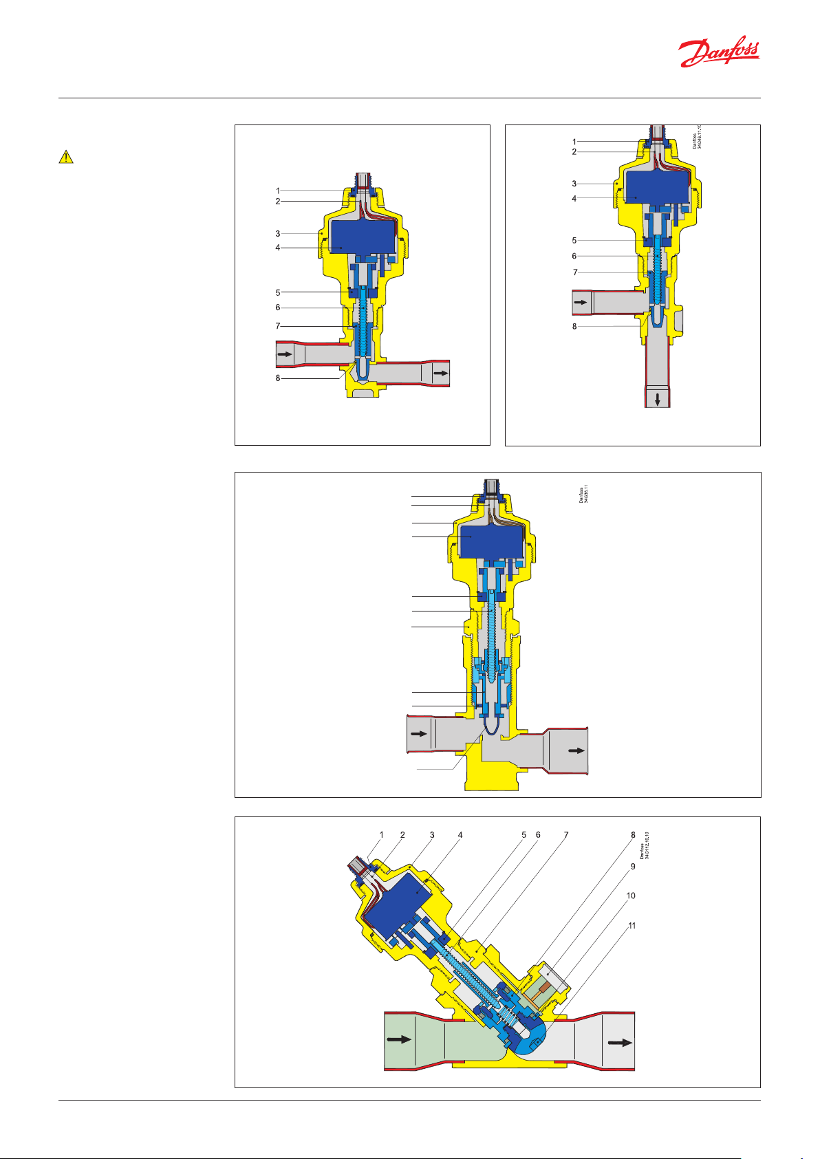
Design
Note:
Flow direction from A to B
refers to the normal flow
Danfoss
34G45.12.10
1. M12 connection
2. Glass seal
3. AST motor housing
4. Stepper motor
5. Bearing
6. Spindle
7. Cone and lead nut
8. Valve seat
1. M12 connector
2. Glass seal
3. AST motor housing
4. Stepper motor
5. Bearing
6. Spindle
7. Top Nut
8. Valve piston
9. Valve seat
10. Valve cone
ETS 12.5, ETS 25 - straight
ETS 50 & 100
B
B
ETS 12.5, ETS 25 - angleway
1
2
3
4
5
6
7
8
9
10
.10
B
1. M12 connector
2. Glass seal
3. AST motor housing
4. Stepper motor
5. Bearing
6. Spindle
7. Top Nut
8. Valve piston
A
B
9. Sight glass with indicator
10. Valve seat
11. Valve cone
© Danfoss | DCS (rm) | 2019.02
ETS 250 & 400
DKRCC.PD.VD1.3C.02 | 3
Page 4
Data sheet | Electric expansion valve, type ETS 12.5 – ETS 400
Sight glass and indicator
Electrical wiring
ETS 50, ETS 100, ETS 250 and ETS 400 are
equipped with sight glass with moisture
indicator. The physical position of the piston in
the valve can be checked through the sight glass.
It also helps to determine the flow direction of
Insufficient sub cooling can produce flash gas
which is visible through the sight glass. The
moisture indicator in the sight glass indicates
dry or wet state of the refrigerant by changing its
colour.
the refrigerant in the system (ETS 50 and
ETS 100).
Danfoss
34G212.10
Note:
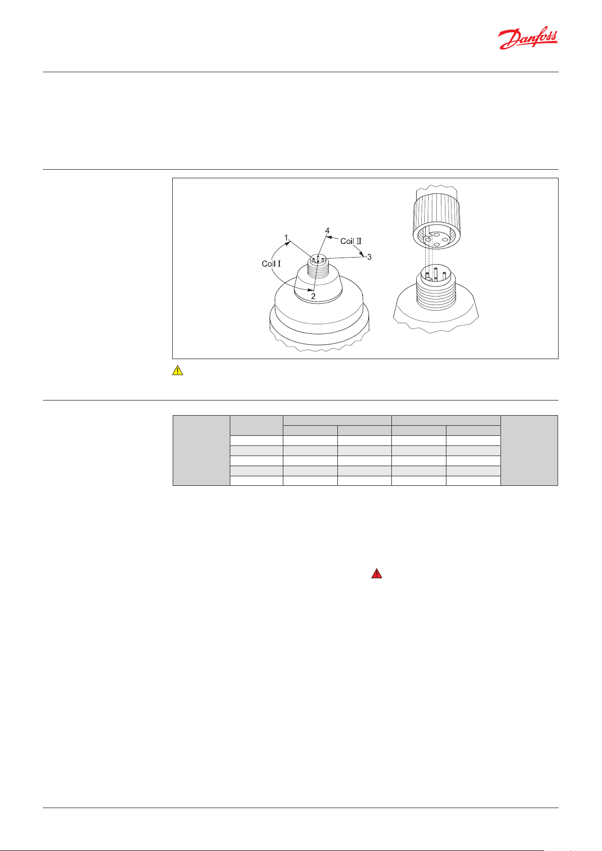
Electrical check of stepper motor and wiring: Coil I = 52 ohm, coil II = 52 ohm
Stepper motor
switch sequence
Coil I Coil II
Red Green White Black
↑ CLOSING ↑
STEP
1 + - + 2 + - - +
3 - + - +
4 - + + 1 + - + -
If the controller driving the ETS valve is from
another manufacturer than Danfoss or a custom
design, the following points must be considered
in order to overcome potential step loss.
a. To ensure total closing of the valve, the
controller should have a function to overdrive
the valve in the closing direction. It is
recommended to overdrive ten percent of the
full step range at appropriate intervals.
↓ OPENING ↓
b. The amount of lost steps may increase as a
function of the amount of changes of the
opening degree. Such designed controller
should be able to compensate the lost steps
after a defined number of changes in opening
degree.
Warning:
At power failure the ETS valve will remain in
the opening position it has at the moment
of power failure, unless a safety device in the
form of a battery backup is installed.
© Danfoss | DCS (rm) | 2019.02
DKRCC.PD.VD1.3C.02 | 4
Page 5
Data sheet | Electric expansion valve, type ETS 12.5 – ETS 400
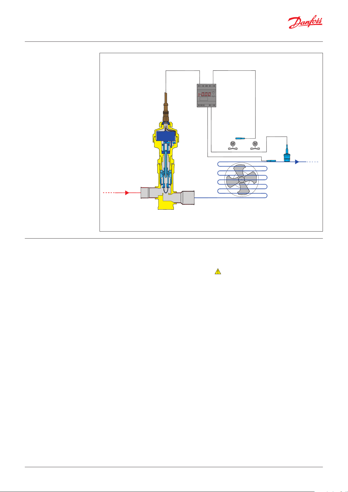
Valve application
Controller/Driver
Temperature sensor
Danfoss
93G18.14
ETS
Valve operation The ETS valves operate modulating by
electronically controlled activation of the AST
stepper motor. The motor is a type 2-phase
bi-polar, which stays in position, unless power
pulses from a driver initiate the two discrete sets
of motor stator windings for rotation in either
directions.
The direction of the rotation of the spindle
depends on the phase relationship of the power
pulses. This is decisive for the travel of the piston.
The motor is operating the spindle, whose
rotating movements are transformed into linear
motion by the transmission in the cage assembly.
The AST motor housing has a glass sealed M12
connection as standard, which can be connected
with customized cable and plug/socket
combinations.
Temperature sensor
Evaporator
Pressure transmitter
Operating the ETS series requires a controller
with either 12 V DC voltage drive (5.5 W) or using
chopper current drive (100 mA RMS).
Note:
Depending on the type of controller or driver,
there will be limitations in cable length between
valve actuator and driver.
Both the actual cable length, the level of EMC
emission on the location and driver circuit has an
impact on the actual distortion of the current to
the actuator motor.
In order to increase max. cable length
considerably, install a 10 mH filter type Danfoss
AKA 211 on the four power terminals.
Please contact Danfoss for further information
how and when to apply this countermeasure in
cases with questionable cable length.
© Danfoss | DCS (rm) | 2019.02
The piston design inside the ETS valve is pressure
balanced, giving identical bi-flow performance
capabilities and nearby identical maximum
capacities.
Closing the valve by overdriving, ensures that the
reference number in steps is always correct.
DKRCC.PD.VD1.3C.02 | 5
Page 6
34G181.10
Data sheet | Electric expansion valve, type ETS 12.5 – ETS 400
Coolselector2®
For easy and precise selection of valve, use Danfoss’ CoolSelector2® software. You can find the ETS
valves on the group, “Electronic expansion valves”.
You can download it from http://coolselector.danfoss.com
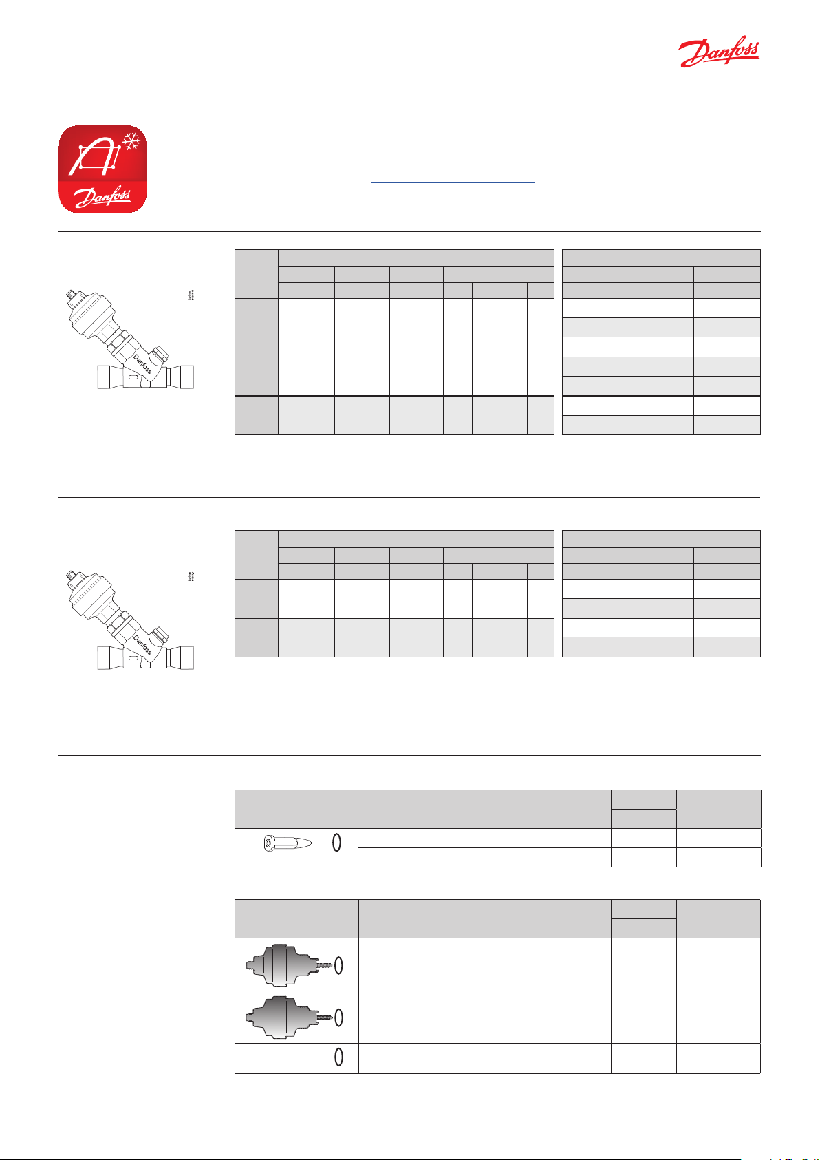
ETS 250, ETS 400
Valve incl. actuator
A B
ETS for oil free applications
Valve incl. actuator
A B
Rated capacity1 Connection
Type
R410A R407C R22 R134a R404A ODF × ODF (A × B) Code no.
[kW] [TR] [kW] [TR] [kW] [TR] [kW] [TR] [kW] [TR] [in.] [mm] Single pack
ETS 250 – – 1212 349 1106 319 874 252 828 239
ETS 400 – – 1933 556 1764 509 1394 402 1320 381
1
) The Rated capacity is based on:
Evaporating temperature te : 5 °C / 40 °F
Liquid temperature tl : 28 °C / 82 °F
Condensing temperature tc : 32 °C / 90 °F
Full stroke opening in normal flow direction
Rated capacity1 Connection
Type
R410A R407C R22 R134a R404A ODF × ODF (A × B) Code no.
[kW] [TR] [kW] [TR] [kW] [TR] [kW] [TR] [kW] [TR] [in.] [mm] Single pack
Oil free
ETS 250
Oil free
ETS 400
1
) The Rated capacity is based on:
Evaporating temperature te : 5 °C / 40 °F
Liquid temperature tl : 28 °C / 82 °F
Condensing temperature tc : 32 °C / 90 °F
Full stroke opening in normal flow direction
– – 1212 349 1106 319 874 252 828 239
– – 1933 556 1764 509 1394 402 1320 381
1 1/8 × 1 1/
1 3/8 × 1 3/
1 5/8 × 1 5/
28 × 28 034G2600
8
35 × 35 034G2601
8
8
– 034G2602
– 42 × 42 034G2611*
2 1/8 × 2 1/
1 5/8 × 1 5/
2 1/8 × 2 1/
8
8
8
– 034G2624
– 034G3500
54 × 54 034G3501
ETS 250 and ETS 400 have integrated sight glass
except 034G2611.
1 3/8 × 1 3/
1 5/8 × 1 5/
1 5/8 × 1 5/
2 1/8 × 2 1/
35 × 35 034G2625
8
8
8
8
– 034G2626
– 034G3514
54 × 54 034G3515
ETS 250 and ETS 400 have integrated sight glass
Spare parts
© Danfoss | DCS (rm) | 2019.02
For smaller capacities of ETS oil free valves see ETS Colibri
Cone/piston for ETS 12.5 / ETS 25
Items Description
Danfoss
Cone/piston for ETS 12.5 + metal gasket 1 034G2345
Cone/piston for ETS 25 + metal gasket 1 034G2346
Actuator with integrated M12 connection
Items Description
34G179.10
Danfoss
34G179.10
Danfoss
*For oil free spare parts of ETS 250 and ETS 400. Please contact Danfoss.
Actuator with integrated M12 with Ceramic bearing
(incl. metal gasket) for ETS 12.5, ETS 25
Actuator with integrated M12 with ceramic bearing
(incl. metal gasket) for ETS 25B, ETS 50, ETS 100, ETS
250, ETS 400
Metal Gasket 1 034G2344
Quantity
[pcs]
Quantity
[pcs]
1 034G2088
1 034G2087*
DKRCC.PD.VD1.3C.02 | 6
Code no.
Code no.
Page 7

Data sheet | Electric expansion valve, type ETS 12.5 – ETS 400
Note:
ETS valve type ETS 12.5, ETS 25, ETS 50 and ETS 100 are currently in process of being
phased-out, Please select ETS Colibri sizes 12C-100C as a replacement.
For further information see: Colibri.danfoss.com
Ordering
ETS 12.5, ETS 25
Valve incl. actuator
A
Phasing out
B
Type
ETS 12.5
ETS 25
Type
ETS 12.5
ETS 25
Rated capacity1 Connection
R410A R407C R22 R134a R404A ODF × ODF (A × B) Code no.
[kW] [TR] [kW] [TR] [kW ] [TR] [kW] [TR] [kW] [TR] [in.] [mm]
Straight way
Single Pack
½ × ½ – 034G4209
70 20 63 18 57 16 45 13 43 12
– 12 × 12 034G4208
5
/8 × 5/
7
/8 × 7/
16 × 16 034G4210
8
22 × 22 034G4211
8
½ × ½ – 034G4201
144 41 129 37 117 34 93 27 88 25
– 12 × 12 034G4200
5
/8 × 5/
7
/8 × 7/
16 × 16 034G4202
8
22 × 22 034G4203
8
ETS 12.5 and ETS 25 do not feature sight glass
Rated capacity1 Connection
R410A R407C R22 R134a R404A ODF × ODF (A × B) Code no.
[kW] [TR] [kW] [TR] [kW] [TR] [kW] [TR] [kW] [TR] [in.] [mm]
Angle way
Single Pack
½ × ½ – 034G4213
70 20 63 18 57 16 45 13 43 12
– 12 × 12 034G4212
5
/8 × 5/
7
/8 × 7/
16 × 16 034G4214
8
22 × 22 034G4215
8
½ × ½ – 034G4205
144 41 129 37 117 34 93 27 88 25
5
/8 × 5/
7
/8 × 7/
–
12 × 12 034G4204
16 × 16 034G4206
8
22 × 22 034G4207
8
ETS 12.5 and ETS 25 do not feature sight glass
ETS 50, ETS 100
Valve incl. actuator
A
Phasing out
B
ETS for R744 Applications
Phasing out
A
Rated capacity1 Connection
Type
R410A R407C R22 R134a R404A ODF × ODF (A × B) Code no.
[kW] [TR] [kW] [TR] [kW] [TR] [kW] [TR] [kW ] [TR] [in.] [mm] Single pack
ETS 50 262.3 75.7 240.5 69.1 215 62 170 48.9 161.4 46.3
ETS 100 488.4 140.9 447.8 128.7 400.4 115.4 316.5 91.2 300.5 86.6
ETS for R744 can be use as loading/unloading valve
ETS for R744 Applications (PS/MWP = 45.5 bar /
660 psig)
For capacities, please contact Danfoss.
Type
ETS 12.5
ETS 25
Connection
ODF × ODF (A × B)
[in.]
7
/8 × 7/8 in 034G4220
7
/8 × 7/8 in 034G4219
Code no.
Single pack
ETS 50 1 / × 1 / in 034G1714
ETS 100 1 / × 1 / in 034G0515
ETS 50 and ETS 100 have integrated sight glass
7
/8 × 7/
7
/8 × 11/
11/8 × 11/
11/8 × 13/
11/8 × 11/
11/8 × 13/
13/8 × 13/
15/8 × 15/
22 × 22 034G1708
8
22 × 28 034G1705
8
28 × 28 034G1706
8
28 × 35 034G1704
8
28 × 28 034G0507
8
28 × 35 034G0501
8
35 × 35 034G0508
8
8
– 034G0505
ETS 50 and ETS 100 have integrated sight glass
B
© Danfoss | DCS (rm) | 2019.02
DKRCC.PD.VD1.3C.02 | 7
Page 8

Data sheet | Electric expansion valve, type ETS 12.5 – ETS 400
Accessories:
M12 angle cable
Approvals
Specification
M12 angle female connector is intended for use with a standard M12 male connector,
available on stepper motor valves.
This cable is designed to offer high flexibility and small outer diameters with tensile strength.
The angle way M12 cable consist of paired, twisted wires, which decreases mutual influence between
signals transmitted along the cable and reduces influence of external sources of interference.
The cables thus provides a higher degree of protection against lost steps compared to other cables.
RoHS
Jacket PVC - black
Cable outer sheath Oil - resistant
Water proof rating IP 67
Operating temperature range -40 – +80 °C
Wire type Twisted pair, cross section 20 AWG / 0.5 mm2
Cable outer diameter 7.0 mm
Minimum bending radius 10 x cable diameter
Cable combustibility / test Flame retardant / VW-1 / CSA FT - 1
M12 standard EN 61076-2-101
Reference standard UL style 2464 and DIN VDE 0812
LVD directive 2014/35/EU
Ordering
Identification
Connections
Cable Cable length (L) Insulation Packing format Code no.
PVC - black
A2 black
A1 white
2 + 0.089 m / 6.6 + 0.3 ft SR-PVC Single pack 034G7073
8 + 0.3 m / 26.2 +1 ft SR-PVC Single pack 034G7074
Product type
Code no
Manufacturing date
Meters / Feets
Country
B1 red
B2 green
34G210.10
34G211.10
Dimensions
© Danfoss | DCS (rm) | 2019.02
Ø 63 mm / 1/4 inch
8 + 0.3 meters / 26.2 +1 feet
34G209.10
35 mm / 1.4 inch2 + 0.089 meters / 6.6 + 0.3 feet
49 mm / 1.9 inch
DKRCC.PD.VD1.3C.02 | 8
Page 9

Data sheet | Electric expansion valve, type ETS 12.5 – ETS 400
Valve sizing
Valve selection
Step 1
For optimum performance, it is important to
correct the evaporator capacity. Selection is
also dependent on an acceptable pressure drop
across the valve. The evaporator capacity must be
corrected if sub cooling deviates from 4K / 7.2 °F.
In order to select the correct size of ETS you will
need the following information:
Refrigerant: R410A, R407C, R404A, R507, R134a,
R22, R1234ze
• Evaporator capacity Qe in [kW] or [TR]
• Evaporating temperature te in [°C] or [°F]
• Condensing temperature tc in [°C] or [°F]
• Max. acceptable pressure drop in the ETS
valve in [bar] or [psi] ∆p
• Sub cooling ∆t
sub
• Connection size
Example
When selecting the valve it may be necessary to
apply a correction factor to the actual evaporator
capacity. This correction factor is required when
system conditions are different from table
conditions. Selection also depends on having an
acceptable pressure drop across the valve. The
following example illustrates correct selection of
the valve.
Refrigerant: R410A
• Evaporator capacity: Qe = 500 kW / 143 TR
• Condensing temperature: tc = 25 °C / 77 °F
• Condensing pressure: pc = 23 bar / 330 psig
• Evaporating temperature: te = +10 °C / 50 °F
• Evaporating pressure: pe = 9.8 bar / 142 psig
• Liquid Line Loss: pl = 0.5 bar (estimate)
• Max. Pressure drop in the valve:
∆p = pc - pl - pe = 23 - 0.5 - 9.8 = 12.7 bar / 184 psi
• Connection size: 1/ × 1/ in.
Determine the correction factor for sub cooling
∆t
.
sub
From the correction factors table (see below) a
sub cooling of 15K / 27 °F, R410A corresponds to
a factor of 1.15.
Correction factors for sub cooling ∆t
Connection
factor
R22 1.00 1.06 1.11 1.15 1.20 1.25 1.30 1.35 1.39 1.44
R410A 1.00 1.08 1.15 1.21 1.27 1.33 1.39 1.45 1.50 1.56
R407C 1.00 1.08 1.14 1.21 1.27 1.33 1.39 1.45 1.51 1.57
R134a 1.00 1.08 1.13 1.19 1.25 1.31 1.37 1.42 1.48 1.54
R404A/R507 1.00 1.10 1.20 1.29 1.37 1.46 1.54 1.63 1.70 1.78
4 K 10 K 15 K 20 K 25 K 30 K 35 K 40 K 45 K 50 K
7.2 °F 18 °F 27 °F 36 °F 45 °F 54 °F 63 °F 72 °F 81 °F 90 °F
.
sub
Δt
sub
Step 2
Step 3
R410A
Step 4
Corrected evaporator capacity is
Qe (Corrected) = 500 kW/1.15 = 435 kW (124 TR)
Now select the appropriate capacity table, R410A,
and choose the column for an evaporating
temperature of te = 10 °C / 50 °F.
Using the corrected evaporator capacity, select
a valve that provides an equivalent or greater
ETS 100 delivers 503.8 kW / 143 TR at 14 bar
which is slightly higher than 12.7 bar / 184 psi
pressure drop across the valve. Based on the
required connection size of 1
1
/
in., the ETS 100 is
8
the proper selection for this example.
capacity at an acceptable pressure drop across
the valve of 12.7 bar / 184 psi.
Rated capacity [kW] in the normal flow direction
t
e
[°C]
2 4 6 8 10 12 14 16 2 4 6 8 10 12 14 16
-40 173.7 224.6 255.1 275.5 289.5 299.2 305.7 309.6 323.5 418.1 475.0 512.9 539.1 557.2 569.2 576.4
-30 169.3 220.8 252.3 273.5 288.3 298.6 305.7 310.1 315.2 411.2 469.7 509.2 536.8 556.1 569.2 577.5
-20 163.3 214.9 246.8 268.6 284.1 295.0 302.5 307.4 304.0 400.1 459.6 500.2 528.9 549.2 563.3 572.4
-10 155.9 206.8 238.8 260.9 276.6 287.9 295.8 301.0 290.3 385.0 444.6 485.7 515.1 536.1 550.8 560.5
-5 151.7 202.0 233.7 255.8 271.6 283.0 291.0 296.4 282.5 376.0 435.2 476.3 505.8 527.0 541.9 551.8
10 137.5 184.5 214.8 236.1 251.5 262.7 270.6 275.8 256.0 343.5 399.9 439.6 468.3 489.1 503.8 513.6
ETS 100, 1
ETS 50 ETS 100
Pressure drop p [bar]
1
1
/
x 1
/
in. connection size:
8
8
Single pack code no. 034G0507.
Note:
For easy and precise selection of valve, use Danfoss’ CoolSelector software. You can download it from
http://www.danfoss.com/businessareas/refrigerationandairconditioning/
product+selection+tools+details/coolselector.htm
© Danfoss | DCS (rm) | 2019.02
DKRCC.PD.VD1.3C.02 | 9
Page 10

Data sheet | Electric expansion valve, type ETS 12.5 – ETS 400
Correction for subcooling
t
sub
Rated Capacity [kW]
t
e
[°C]
2 4 6 8 10 12 14 16 2 4 6 8 10 12 14 16
-40 46.4 60.0 68.1 73.5 77.3 79.9 81.6 82.6 95.3 123.2 140.0 151.1 158.8 164.1 167.7 169.8
-30 45.2 59.0 67.3 73.0 76.9 79.7 81.6 82.7 92.9 121.2 138.4 150.0 158.1 163.8 167.7 170.1
R410A
R407C
R22
R134a
R404A
-20 43.6 57.4 65.9 71.7 75.8 78.7 80.7 82.0 89.6 117.9 135.4 147.4 155.8 161.8 165.9 168.6
-10 41.6 55.2 63.7 69.6 73.8 76.8 78.9 80.3 85.5 113.5 131.0 143.1 151.7 157.9 162.2 165.0
-5 40.5 53.9 62.4 68.3 72.5 75.5 77.6 79.0 83.3 110.8 128.2 140.3 149.0 155.2 159.6 162.5
10 36.7 49.2 57.3 63.0 67.1 70.1 72.2 73.5 75.4 101.2 117.8 129.5 137.9 144.0 148.3 151.2
-40 42.1 52.8 58.6 62.0 63.9 64.9 65.0 64.6 86.5 108.5 120.5 127.5 131.4 133.3 133.6 132.7
-30 41.9 53.0 59.2 63.0 65.2 66.3 66.7 66.4 86.0 109.0 121.7 129.4 133.9 136.3 137.1 136.6
-20 41.2 52.8 59.3 63.4 65.8 67.2 67.8 67.8 84.7 108.5 121.9 130.2 135.3 138.2 139.4 139.3
-10 40.2 52.0 58.8 63.1 65.9 67.5 68.3 68.4 82.6 106.9 120.9 129.8 135.4 138.7 140.3 140.6
-5 39.6 51.4 58.4 62.8 65.6 67.3 68.2 68.4 81.3 105.7 120.0 129.0 134.9 138.4 140.2 140.6
10 37.1 48.9 56.0 60.6 63.7 65.5 66.7 67.1 76.3 100.5 115.0 124.6 130.9 134.8 137.1 138.0
-40 40.2 51.3 57.9 62.1 65.0 66.9 68.0 68.6 82.6 105.5 118.9 127.7 133.6 137.5 139.8 141.1
-30 39.8 51.3 58.1 62.6 65.7 67.7 69.1 69.8 81.8 105.4 119.4 128.7 135.0 139.2 142.0 143.5
-20 39.1 50.8 57.9 62.6 65.9 68.1 69.6 70.4 80.3 104.4 118.9 128.7 135.4 140.0 143.0 144.8
-10 38.0 49.9 57.1 62.1 65.5 67.9 69.5 70.5 78.1 102.5 117.4 127.5 134.6 139.5 142.8 144.9
-5 37.4 49.3 56.6 61.6 65.1 67.5 69.2 70.2 76.9 101.2 116.3 126.5 133.7 138.8 142.2 144.4
10 35.2 46.8 54.1 59.2 62.9 65.4 67.2 68.4 72.3 96.2 111.3 121.7 129.2 134.5 138.2 140.6
-40 35.6 43.2 46.8 48.5 49.0 48.6 47.7 46.3 73.1 88.8 96.3 99.7 100.7 100.0 98.0 95.1
-30 35.8 44.0 48.0 50.0 50.7 50.6 49.9 48.6 73.5 90.4 98.6 102.7 104.2 104.0 102.5 99.9
-20 35.6 44.3 48.8 51.1 52.1 52.2 51.7 50.6 73.3 91.1 100.2 105.0 107.0 107.3 106.2 104.0
-10 35.2 44.3 49.1 51.7 53.0 53.3 53.0 52.1 72.3 91.0 100.9 106.2 108.8 109.6 108.9 107.1
-5 34.8 44.1 49.0 51.8 53.2 53.7 53.4 52.6 71.6 90.6 100.8 106.4 109.3 110.3 109.8 108.2
10 33.3 42.8 48.1 51.2 53.0 53.7 53.8 53.2 68.3 88.0 98.9 105.3 108.9 110.4 110.5 109.4
-40 31.9 39.6 43.4 45.2 45.9 45.8 45.0 43.8 65.7 81.4 89.2 93.0 94.3 94.0 92.5 90.0
-30 31.5 39.5 43.6 45.8 46.7 46.7 46.2 45.1 64.7 81.2 89.7 94.0 95.9 96.1 94.9 92.8
-20 30.7 39.0 43.3 45.7 46.9 47.1 46.8 45.9 63.0 80.1 89.1 94.0 96.3 96.9 96.1 94.3
-10 29.5 37.9 42.5 45.1 46.4 46.9 46.7 45.9 60.7 78.0 87.4 92.7 95.4 96.3 95.9 94.4
-5 28.9 37.3 41.9 44.6 46.0 46.5 46.3 45.6 59.4 76.6 86.1 91.6 94.5 95.5 95.2 93.8
10 26.5 34.6 39.2 41.9 43.5 44.1 44.1 43.5 54.4 71.0 80.5 86.2 89.3 90.6 90.6 89.4
The evaporator capacities used must be corrected
if subcooling deviates from 4 K / 7.2 °F.
The corrected capacity can be obtained by
dividing the required evaporator capacity by the
correction factor. Selections can then be made
from the tables below.
t
sub
Correction factor
R22 1.00 1.06 1.11 1.15 1.20 1.25 1.30 1.35 1.39 1.44
R410A 1.00 1.08 1.15 1.21 1.27 1.33 1.39 1.45 1.50 1.56
R407C 1.00 1.08 1.14 1.21 1.27 1.33 1.39 1.45 1.51 1.57
R134a 1.00 1.08 1.13 1.19 1.25 1.31 1.37 1.42 1.48 1.54
R404A / R507 1.00 1.10 1.20 1.29 1.37 1.46 1.54 1.63 1.70 1.78
4 K 10 K 15 K 20 K 25 K 30 K 35 K 40 K 45 K 50 K
7.2 °F 18 °F 27 °F 36 °F 45 °F 54 °F 63 °F 72 °F 81 °F 90 °F
Note:
Insufficient subcooling can produce flash gas.
SI units
Rated capacity [kW] in the normal flow direction
ETS 12.5 ETS 25
Pressure drop p [bar]
© Danfoss | DCS (rm) | 2019.02
DKRCC.PD.VD1.3C.02 | 10
Page 11

Data sheet | Electric expansion valve, type ETS 12.5 – ETS 400
Rated Capacity [kW]
SI units
t
e
[°C]
2 4 6 8 10 12 14 16 2 4 6 8 10 12 14 16
-40 173.7 224.6 255.1 275.5 289.5 299.2 305.7 309.6 323.5 418.1 475.0 512.9 539.1 557.2 569.2 576.4
-30 169.3 220.8 252.3 273.5 288.3 298.6 305.7 310.1 315.2 411.2 469.7 509.2 536.8 556.1 569.2 577.5
R410A
R407C
R22
R134a
R404A
The capacities stated in the tables are for the normal flow direction. For ETS 50 and 100 specifically, the capacity in reverse flow direction varies between 90% and 125% of the
capacity in normal flow direction.
-20 163.3 214.9 246.8 268.6 284.1 295.0 302.5 307.4 304.0 400.1 459.6 500.2 528.9 549.2 563.3 572.4
-10 155.9 206.8 238.8 260.9 276.6 287.9 295.8 301.0 290.3 385.0 444.6 485.7 515.1 536.1 550.8 560.5
-5 151.7 202.0 233.7 255.8 271.6 283.0 291.0 296.4 282.5 376.0 435.2 476.3 505.8 527.0 541.9 551.8
10 137.5 184.5 214.8 236.1 251.5 262.7 270.6 275.8 256.0 343.5 399.9 439.6 468.3 489.1 503.8 513. 6
-40 158.5 199.3 222.0 235.6 243.8 248.1 249.7 249.1 295.1 371.2 413.3 438.7 453.9 462.0 464.9 463.8
-30 157.6 200.3 224.4 239.3 248.5 253.7 256.1 256.2 293.5 373.0 417.8 445.5 462.6 472.5 476.9 477.1
-20 155.3 199.5 224.9 241.0 251.2 257.3 260.5 261.3 289.2 371.5 418.8 448.7 467.7 479.2 485.1 486.6
-10 151.7 196.8 223.3 240.4 251.5 258.5 262.5 263.9 282.4 366.4 415.9 447.6 468.4 481.4 488.7 491.4
-5 149.4 194.7 221.7 239.2 250.8 258.1 262.4 264.2 278.1 362.6 412.8 445.4 466.9 480.6 488.6 491.9
10 140.7 185.7 213.2 231.6 244.0 252.3 257.4 259.9 261.9 345.7 397.0 431.2 454.4 469.8 479.2 483.9
-40 151.5 193.5 218.1 234.2 245.1 252.2 256.6 258.8 282.1 360.2 406.2 436.2 456.3 469.6 477.7 481.9
-30 149.9 193.2 218.9 236.0 247.6 255.4 260.4 263.1 279.1 359.7 407.6 439.4 460.9 475.5 484.8 489.9
-20 147.1 191.3 218.0 235.9 248.2 256.6 262.2 265.5 273.9 356.2 405.9 439.2 462.1 477.9 488.2 494.3
-10 143.2 187.8 215.2 233.8 246.7 255.7 261.8 265.6 266.6 349.7 400.8 435.3 459.4 476.2 487.5 494.5
-5 140.8 185.5 213.1 231.9 245.1 254.4 260.7 264.6 262.3 345.4 396.8 431.8 456.4 473.7 485.4 492.8
10 132.4 176.2 203.9 223.0 236.7 246.5 253.2 257.6 246.5 328.1 379.6 415.3 440.8 458.9 471.5 479.7
-40 133.1 161.8 175.4 181.6 183.4 182.1 178.6 173.3 247.8 301.3 326.6 338.2 341.5 339.1 332.5 322.6
-30 133.9 164.7 179.7 187.1 189.9 189.5 186.7 182.1 249.3 306.6 334.6 348.5 353.6 352.8 347.6 339.0
-20 133.4 166.1 182.6 191.2 195.0 195.4 193.4 189.5 248.4 309.2 340.0 356.0 363.1 363.9 360.1 352.8
-10 131.7 165.9 183.7 193.5 198.3 199.6 198.3 195.1 245.2 308.8 342.1 360.3 369.2 371.6 369.3 363.3
-5 130.3 165.1 183.6 193.9 199.2 200.9 200.0 197.1 242.6 307.4 341.9 361.1 370.8 374.1 372.4 367.0
10 124.5 160.3 180.2 191.9 198.3 201.2 201.3 199.3 231.8 298.5 335.5 357.2 369.3 374.6 374.8 371.1
-40 119.8 148.6 162.8 169.8 172.3 171.9 169.2 164.7 223.0 276.6 303.1 316.1 320.9 320.0 315.0 306.7
-30 118.0 148.2 163.7 171.7 175.2 175.6 173.6 169.8 219.7 276.0 304.7 319.7 326.2 326.9 323.2 316.1
-20 115.0 146.1 162.6 171.6 176.0 177.1 175.7 172.5 214.0 272.1 302.8 319.6 327.6 329.7 327.2 321.3
-10 110.8 142.3 159.5 169.3 174.4 176.1 175.4 172.7 206.3 265.0 297.1 315.2 324.6 327.9 326.6 321.5
-5 108.3 139.8 157.2 167.3 172.6 174.6 174.1 171.7 201.7 260.3 292.7 311.4 321.4 325.1 324.2 319.7
10 99.4 129.7 147.1 157.5 163.3 165.8 165.8 163.7 185.0 241.6 273.9 293.2 304.0 308.7 308.6 304.8
ETS 50 ETS 100
Rated capacity [kW] in the normal flow direction
Pressure drop p [bar]
© Danfoss | DCS (rm) | 2019.02
DKRCC.PD.VD1.3C.02 | 11
Page 12

Data sheet | Electric expansion valve, type ETS 12.5 – ETS 400
Rated Capacity [kW]
Rated capacity [kW] in the normal flow direction
ETS 250 ETS 400
R407C
R22
R134a
R404A
t
e
[°C]
2 4 6 8 10 12 14 16 2 4 6 8 10 12 14 16
-40 811 1017 1129 1195 1232 1249 1252 1244 1294 1622 1801 1905 1964 1992 1997 1984
-30 806 1022 1141 1213 1255 1277 1284 1280 1286 1629 1820 1934 2002 2037 2049 2041
-20 794 1017 1143 1220 1268 1295 1306 1305 1266 1621 1823 1947 2023 2065 2083 2082
-10 774 1002 1133 1216 1269 1300 1315 1317 1235 1598 1808 1940 2024 2073 2097 2101
-5 762 990 1124 1209 1264 1297 1314 1318 1215 1580 1793 1929 2016 2068 2095 2102
10 715 941 1078 1167 1226 1264 1285 1293 1141 1502 1719 1862 1956 2016 2049 2062
-40 779 995 1122 1205 1261 1297 1320 1331 1243 1587 1790 1922 2011 2069 2105 2123
-30 771 994 1126 1214 1273 1314 1339 1353 1230 1585 1796 1936 2031 2095 2136 2159
-20 757 984 1121 1213 1277 1320 1349 1366 1207 1569 1789 1935 2036 2106 2151 2178
-10 737 966 1107 1202 1269 1315 1347 1366 1175 1541 1766 1918 2024 2098 2148 2179
-5 724 954 1096 1193 1261 1309 1341 1361 1156 1522 1748 1903 2011 2087 2139 2171
10 681 906 1049 1147 1218 1268 1303 1325 1086 1446 1673 1830 1942 2022 2078 2114
-40 684 832 902 934 943 937 919 891 1092 1328 1439 1490 1505 1494 1465 1422
-30 688 847 924 963 977 975 960 937 1098 1351 1474 1535 1558 1555 1532 1494
-20 686 854 939 983 1003 1005 995 975 1094 1362 1498 1569 1600 1603 1587 1555
-10 677 853 945 995 1020 1027 1020 1003 1080 1360 1507 1587 1627 1637 1627 1600
-5 670 849 944 997 1024 1033 1029 1014 1069 1354 1506 1591 1634 1648 1641 1617
10 640 824 927 987 1020 1035 1035 1025 1021 1315 1478 1574 1627 1650 1651 1635
-40 615 763 836 871 884 881 867 844 981 1217 1333 1390 1410 1406 1383 1346
-30 606 761 840 881 899 900 890 870 967 1214 1340 1406 1434 1436 1419 1387
-20 591 750 835 881 903 908 901 884 942 1197 1332 1405 1440 1448 1437 1410
-10 569 731 819 869 894 903 899 884 908 1166 1306 1386 1426 1440 1433 1411
-5 556 718 807 858 885 895 892 879 887 1145 1287 1369 1412 1428 1423 1402
10 510 666 755 807 837 849 849 838 814 1062 1204 1288 1335 1355 1354 1336
SI units
Pressure drop p [bar]
© Danfoss | DCS (rm) | 2019.02
DKRCC.PD.VD1.3C.02 | 12
Page 13

Data sheet | Electric expansion valve, type ETS 12.5 – ETS 400
Rated Capacity [TR]
(TR = ton of refrigeration)
Rated capacity [TR] in the normal flow direction
ETS 12.5 ETS 25
R410A
R407C
R22
R134a
R404A
t
e
[°F]
40 60 80 100 125 150 175 200 40 60 80 100 125 150 175 200
-40 14.9 17.2 18.9 20.1 21.3 22.1 22.7 23.2 30.7 35.5 38.8 41.4 43.7 45.5 46.7 47.6
-20 14.6 16.9 18.6 19.9 21.1 22.0 22.7 23.1 29.9 34.8 38.3 40.9 43.4 45.2 46.6 47.6
0 14.0 16.4 18.1 19.4 20.7 21.6 22.3 22.8 28.8 33.7 37.2 39.9 42.5 44.4 45.9 46.9
20 13.3 15.7 17.4 18.7 20.0 20.9 21.6 22.2 27.4 32.2 35.7 38.4 41.0 43.0 44.5 45.5
40 12.5 14.7 16.4 17.7 18.9 19.9 20.6 21.1 25.7 30.3 33.7 36.4 38.9 40.9 42.3 43.4
50 12.0 14.2 15.8 17.1 18.3 19.2 19.9 20.5 24.7 29.2 32.5 35.1 37.6 39.6 41.0 42.1
-40 13.4 15.2 16.3 17.2 17.8 18.2 18.4 18.5 27.5 31.2 33.6 35.3 36.7 37.5 37.9 38.0
-20 13.4 15.2 16.5 17.4 18.2 18.6 18.9 19.0 27.5 31.3 33.9 35.8 37.3 38.3 38.8 39.1
0 13.2 15.1 16.5 17.4 18.3 18.8 19.2 19.3 27.1 31.1 33.9 35.9 37.6 38.7 39.4 39.7
20 12.8 14.8 16.3 17.3 18.2 18.8 19.2 19.4 26.4 30.5 33.4 35.5 37.4 38.6 39.4 39.9
40 12.4 14.4 15.8 16.9 17.8 18.5 18.9 19.2 25.4 29.5 32.5 34.7 36.6 38.0 38.9 39.4
50 12.1 14.1 15.5 16.6 17.5 18.2 18.7 18.9 24.8 28.9 31.9 34.1 36.1 37.4 38.4 38.9
-40 12.9 14.8 16.1 17.1 18.0 18.6 19.0 19.3 26.5 30.3 33.1 35.1 36.9 38.2 39.1 39.7
-20 12.8 14.7 16.1 17.2 18.1 18.8 19.3 19.6 26.3 30.3 33.1 35.3 37.2 38.7 39.7 40.4
0 12.6 14.6 16.0 17.1 18.1 18.8 19.4 19.8 25.8 29.9 32.9 35.1 37.2 38.7 39.8 40.6
20 12.2 14.2 15.7 16.8 17.9 18.7 19.3 19.7 25.1 29.3 32.3 34.6 36.8 38.4 39.6 40.4
40 11.7 13.8 15.3 16.4 17.5 18.3 18.9 19.3 24.1 38.3 31.4 33.7 35.9 37.6 38.9 39.7
50 11.5 13.5 15.0 16.1 17.2 18.0 18.6 19.1 23.6 27.7 30.8 33.1 35.4 37.4 38.3 39.2
-40 11.2 12.4 13.1 13.6 13.9 13.9 13.8 13.6
-20 11.3 12.6 13.5 14.0 14.3 14.5 14.5 14.3
0 11.3 12.7 13.7 14.3 14.7 14.9 14.9 14.8
20 11.2 12.7 13.7 14.4 14.9 15.1 15.2 15.2
40 10.9 12.5 13.5 14.3 14.8 15.2 15.3 15.3
50 10.7 12.3 13.4 14.1 14.8 15.3 15.1 15.3
-40 10.1 11.4 12.1 12.6 12.9 13.1 13.0 12.8 20.8 23.4 25.0 25.9 26.6 26.8 26.7 26.4
-20 10.0 11.3 12.2 12.7 13.1 13.3 13.3 13.2 20.6 23.3 25.0 26.2 27.0 27.3 27.4 27.1
0 9.8 11.1 12.0 12.6 13.1 13.4 13.4 13.3 20.0 22.9 24.8 26.0 27.0 27.4 27.5 27.4
20 9.4 10.8 11.7 12.4 12.9 13.2 13.3 13.2 19.3 22.2 24.1 25.4 26.5 27.0 27.3 27.2
40 8.9 10.3 11.2 11.9 12.4 12.7 12.9 12.8 18.2 21.1 23.0 24.4 25.5 26.1 26.4 26.4
50 8.6 9.9 10.9 11.5 12.1 12.4 12.5 12.5 17.6 20.4 22.4 23.7 24.9 25.5 25.8 25.8
US units
Pressure drop p [psi]
22.9 25.5 27.0 27.9 28.5 28.6 28.4 27.9
23.2 26.0 27.7 28.8 29.5 29.8 29.7 29.3
23.2 26.2 28.1 29.3 30.2 30.6 30.7 30.4
22.9 26.1 28.1 29.5 30.6 31.1 31.3 31.2
22.4 25.6 27.8 29.3 30.5 31.2 31.5 31.5
22.0 25.3 27.5 29.1 30.3 31.1 31.4 31.4
© Danfoss | DCS (rm) | 2019.02
DKRCC.PD.VD1.3C.02 | 13
Page 14

Data sheet | Electric expansion valve, type ETS 12.5 – ETS 400
Rated Capacity [TR]
(TR = ton of refrigeration)
US units
Rated capacity [TR] in the normal flow direction
t
e
[°F]
40 60 80 100 125 150 175 200 40 60 80 100 125 150 175 200
-40 55.9 64.6 70.8 75.4 79.7 82.9 85.2 86.8 104.2 120.3 131.8 140.4 148.5 154.4 158.6 161.6
-20 54.6 63.4 69.8 74.6 79.1 82.5 85.0 86.7 101.6 118.0 129.9 138.9 147.4 153.6 158.2 161.5
R410A
R407C
R22
R134a
R404A
The capacities stated in the tables are for the normal flow direction. For ETS 50 and 100 specifically, the capacity in reverse flow direction varies between 90% and 125% of the
capacity in normal flow direction.
0 52.6 61.4 67.9 72.8 77.5 81.0 83.6 85.5 97.8 114.3 126.4 135.6 144.3 150.9 155.7 159.2
20 49.9 58.7 65.1 70.1 74.8 78.4 81.1 83.1 93.0 109.2 121.2 130.4 139.3 146.0 151.0 154.6
40 46.8 55.2 61.4 66.3 71.0 74.6 77.2 79.2 87.1 102.7 114.4 123.5 132.2 138.8 143.8 147.5
50 45.0 53.2 59.3 64.1 68.7 72.2 74.8 76.8 83.8 99.0 110.4 119.3 127.8 134.4 139.3 142.9
-40 50.4 57.3 61.9 65.1 67.9 69.6 70.6 71.0 93.9 106.6 115.2 121.2 126.4 129.6 131.5 132.2
-20 50.4 57.6 62.5 66.0 69.1 71.1 72.4 73.0 93.8 107.2 116.4 122.9 128.7 132.4 134.7 135.9
0 49.7 57.2 62.5 66.3 69.6 71.9 73.4 74.2 92.6 106.6 116.3 123.4 129.6 133.9 136.6 138.2
20 48.5 56.2 61.7 65.7 69.3 71.8 73.5 74.6 90.4 104.7 114.9 122.3 129.1 133.8 136.9 138.8
40 46.8 54.6 60.1 64.3 68.1 70.8 72.7 73.9 87.1 101.6 111.9 119.7 126.8 131.8 135.3 137.5
50 45.7 53.5 59.0 63.2 67.1 69.9 71.8 73.1 85.2 99.5 109.9 117.7 125.0 130.1 133.7 136.1
-40 48.5 55.6 60.6 64.3 67.7 70.1 71.8 72.9 90.3 103.6 112.9 119.8 126.1 130.5 133.7 135.7
-20 48.1 55.5 60.8 64.7 68.3 70.9 72.8 74.0 89.6 103.4 113.1 120.4 127.2 132.0 135.5 137.8
0 47.3 54.9 60.3 64.4 68.2 71.0 73.1 74.5 88.1 102.2 112.3 119.9 127.1 132.3 136.0 138.7
20 46.0 53.6 59.2 63.5 67.5 70.4 72.6 74.1 85.6 99.9 110.3 118.1 125.6 131.1 135.1 138.0
40 44.2 51.9 57.5 61.8 65.9 68.9 71.2 72.9 82.3 96.6 107.0 115.0 122.7 128.4 132.6 135.7
50 43.2 50.8 56.4 60.7 64.8 67.9 70.2 71.9 80.4 94.5 104.9 112.9 120.6 126.4 130.7 133.8
-40 41.8 46.4 49.2 50.9 51.9 52.2 51.8 50.9
-20 42.3 47.3 50.4 52.4 53.8 54.2 54.1 53.4
0 42.3 47.7 51.1 53.4 55.1 55.8 55.9 55.5
20 41.8 47.5 51.3 53.8 55.7 56.7 57.0 56.8
40 40.8 46.7 50.7 53.4 55.6 56.9 57.4 57.4
50 40.1 46.1 50.1 53.0 55.3 56.6 57.2 57.3
-40 37.9 42.6 45.6 47.4 48.6 49.0 48.9 48.2 70.6 79.4 84.8 88.2 90.5 91.3 91.0 89.8
–20 37.5 42.5 45.7 47.8 49.3 50.0 50.0 49.6 69.9 79.2 85.1 89.0 91.8 93.0 93.1 92.3
0 36.6 41.8 45.2 47.5 49.2 50.1 50.4 50.1 68.1 77.8 84.2 88.4 91.7 93.3 93.8 93.3
20 35.2 40.5 44.0 46.4 48.4 49.4 49.8 49.7 65.5 75.3 81.9 86.4 90.1 92.0 92.8 92.6
40 33.3 38.5 42.1 44.6 46.6 47.8 48.3 48.3 62.0 71.7 78.4 83.0 86.8 89.0 90.0 89.9
50 32.2 37.3 40.9 43.4 45.4 46.6 47.2 47.2 59.9 69.5 76.1 80.7 84.6 86.8 87.8 87.8
ETS 50 ETS 100
Pressure drop p [psi]
77.7 86.4 91.6 94.7 96.7 97.1 96.4 94.8
78.7 88.1 93.9 97.6 100.1 101.0 100.7 99.5
78.7 88.8 95.2 99.4 102.5 103.9 104.1 103.3
77.8 88.5 95.4 100.1 103.7 105.6 106.2 105.8
75.9 87.0 94.4 99.5 103.6 105.9 106.9 106.8
74.6 85.8 93.4 98.6 102.9 105.4 106.6 106.7
© Danfoss | DCS (rm) | 2019.02
DKRCC.PD.VD1.3C.02 | 14
Page 15

Data sheet | Electric expansion valve, type ETS 12.5 – ETS 400
Rated Capacity [TR]
(TR = ton of refrigeration)
Rated capacity [TR] in the normal flow direction
ETS 250 ETS 400
R407C
R22
R134a
R404A
t
e
[°F]
40 60 80 100 125 150 175 200 40 60 80 100 125 150 175 200
-40 258 292 315 331 344 351 355 356 411 466 502 527 548 561 567 568
-20 257 293 318 335 350 359 364 366 410 468 507 535 558 573 581 584
0 254 292 317 336 352 363 369 372 405 465 506 536 562 579 589 594
20 247 286 313 333 350 362 369 374 395 456 499 531 559 577 589 596
40 238 277 305 325 343 356 364 369 380 442 486 518 548 568 581 589
50 232 271 299 319 338 351 360 365 371 432 476 509 539 560 574 582
-40 250 286 312 331 348 361 369 375 398 456 497 528 556 575 589 598
-20 248 286 313 333 351 365 374 381 395 455 499 531 560 582 597 607
0 243 282 310 331 351 365 376 383 388 450 495 528 560 583 599 611
20 236 276 305 326 347 362 373 381 377 440 486 521 553 578 595 608
40 227 267 296 318 339 355 366 375 363 425 471 507 540 566 584 598
50 222 261 290 312 333 349 361 370 354 416 462 498 531 557 576 590
-40 215 239 253 262 267 268 266 262 342 381 404 417 426 428 425 418
-20 217 243 259 269 276 279 278 275 347 388 414 430 441 445 444 439
0 217 245 263 275 283 287 288 285 347 391 420 438 452 458 459 455
20 215 244 264 276 286 292 293 292 343 390 420 441 457 465 468 466
40 210 240 261 275 286 292 295 295 334 383 416 438 456 466 471 470
50 206 237 258 272 284 291 294 295 329 378 411 434 453 464 469 470
-40 195 219 234 243 249 252 251 247 311 349 373 388 398 401 400 394
-20 193 218 235 245 253 256 256 254 307 348 374 391 403 409 409 405
0 188 215 232 244 253 257 258 257 300 342 370 389 403 410 412 410
20 181 208 226 238 248 253 256 255 288 331 360 380 396 404 408 406
40 171 198 216 229 239 245 248 247 273 315 344 365 381 391 395 395
50 165 192 210 222 233 239 242 242 263 306 334 355 371 381 385 385
US units
Pressure drop p [psi]
© Danfoss | DCS (rm) | 2019.02
DKRCC.PD.VD1.3C.02 | 15
Page 16

Data sheet | Electric expansion valve, type ETS 12.5 – ETS 400
Capacity
Normal flow direction
ETS 12.5
[kW]Q
0
Q
Opening [%]
[kW]Q
0
Q
ETS 50
[kW]Q
0
[kW]Q
0
ETS 25
Opening [%]
ETS 100
Opening [%]
ETS 250
[kW]
0
Opening [%]
Capacity based on: R407C
Te = 5 °C / 41 °F
T
= 32 °C / 89.6 °F
c
Tl = 28 °C / 82.4 °F
Opening [%]
ETS 400
[kW]
0
Opening [%]
© Danfoss | DCS (rm) | 2019.02
DKRCC.PD.VD1.3C.02 | 16
Page 17

Data sheet | Electric expansion valve, type ETS 12.5 – ETS 400
Dimensions and weights for
ETS 12.5 and ETS 25
Connections H
Type
ODF × ODF (A × B)
[in.] [mm]
ETS 12.5
and 25
straight
ETS 12.5
and 25
angle
½ × ½ 12 × 12 1.2 30 0.5 13 2.5 64 5.9 150 – – 2.4 60 2.4 60 2.4 60 0.7 1.5
5
/8 × 5/816 × 16 1.2 30 0.5 13 2.5 64 5.9 150 – – 2.4 60 2.4 60 2.4 60 0.7 1.5
7
/8 × 7/822 × 22 1.2 30 0.5 13 2.5 64 5.9 150 – – 2.4 60 2.4 60 2.4 60 0.7 1.5
½ × ½ 12 × 12 1.2 30 – – 2.5 64 7.6 194 2.9 74 2.4 60 – – 2.4 60 0.7 1.5
5
/8 × 5/816 × 16 1.2 30 – – 2.5 64 7.6 194 2.9 74 2.4 60 – – 2.4 60 0.7 1.5
7
/8 × 7/822 × 22 1.2 30 – – 2.5 64 7.6 194 2.9 74 2.4 60 – – 2.4 60 0.7 1.5
Dimensions and weights for
ETS 50 and ETS 100
1
H
2
H
3
H
4
H
5
L
1
L
2
øD
1
Net weight
[in.] [mm] [in.] [mm] [in.] [mm] [in.] [mm] [in.] [mm] [in.] [mm] [in.] [mm] [in.] [mm] [kg] [lb.]
B
Connections H
Type
ODF × ODF (A × B)
[in.] [mm]
7
ETS 50
ETS 100
/8 × 7/
7
/8 × 11/
11/8 × 11/
11/8 × 13/
11/8 × 11/
11/8 × 13/
13/8 × 13/
15/8 × 15/
22 × 22 1.0 26.2 0.5 13.0 4.7 118.0 8.1 205.0 2.2 56.0 2.2 56.0 2.4 60.0 1.5 3.3
8
22 × 28 1.0 26.2 0.5 13.0 4.7 118.0 8.1 205.0 2.2 56.0 2.5 63.0 2.4 60.0 1.5 3.3
8
28 × 28 1.0 26.2 0.5 13.0 4.7 118.0 8.1 205.0 2.5 63.0 2.5 63.0 2.4 60.0 1.5 3.3
8
28 × 35 1.0 26.2 0.5 13.0 4.7 118.0 8.1 205.0 2.5 63.0 2.9 74.0 2.4 60.0 1.5 3.3
8
28 × 28 1.2 30.0 0.7 17.0 5.0 127.0 8.4 214.0 2.6 66.0 2.6 66.0 2.4 60.0 1.7 3.7
8
28 × 35 1.2 30.0 0.7 17.0 5.0 127.0 8.4 214.0 2.6 66.0 3.0 76.0 2.4 60.0 1.7 3.7
8
35 × 35 1.2 30.0 0.7 17.0 5.0 127.0 8.4 214.0 3.0 76.0 3.0 76.0 2.4 60.0 1.7 3.7
8
8
– 1.2 30.0 0.7 17.0 5.0 127.0 8.4 214.0 3.3 84.0 3.3 84.0 2.4 60.0 1.7 3.7
© Danfoss | DCS (rm) | 2019.02
1
H
2
H
3
H
4
L
1
L
2
øD
Net weight
1
[in.] [mm] [in.] [mm] [in.] [mm] [in.] [mm] [in.] [mm] [in.] [mm] [in.] [mm] [kg] [lb.]
DKRCC.PD.VD1.3C.02 | 17
Page 18

Dimensions and weights for
ETS 250 and ETS 400
Type
ETS 250
Connections H
ODF × ODF (A × B)
[in.] [mm]
11/8 × 11/
13/8 × 13/
15/8 × 15/
28 × 28 4.7 120.0 6.7 168.5 5.6 143.0 3.3 83.0 3.4 85.5 2.4 60.0 0.95 24.0 1.9 4.2
8
35 × 35 4.7 120.0 7.0 178.5 5.6 143.0 3.5 88.0 3.6 90.5 2.4 60.0 0.95 24.0 1.9 4.2
8
8
– 4.7 120.0 7.4 188.5 5.6 143.0 3.7 93.0 3.8 95.5 2.4 60.0 0.95 24.0 1.9 4.2
1
[in.] [mm] [in.] [mm] [in.] [mm] [in.] [mm] [in.] [mm] [in.] [mm] [in.] [mm] [kg] [lb.]
L
1
L
2
L
3
L
4
øD
1
– 42 × 42 4.7 120.0 7.4 188.5 5.6 143.0 3.7 93.0 3.8 95.5 2.4 60.0 0.95 24.0 1.9 –
ETS 400
21/8 × 21/
15/8 × 15/
21/8 × 21/
8
8
8
– 4.7 120.0 8.1 204.0 5.6 143.0 4.0 101.0 4.1 103.0 2.4 60.0 0.95 24.0 1.9 4.2
– 4.8 121.0 8.0 203.0 5.7 144.5 3.9 99.0 4.1 104.0 2.4 60.0 0.95 24.0 2.2 4.9
54 × 54 4.8 121.0 9.6 243.0 5.7 144.5 4.7 119.0 4.9 124.0 2.4 60.0 0.95 24.0 2.2 4.9
Related products
EKE 1A, EKE 1B, EKE 1C EKS 221, ACCPBT, AKS 11/AKS 12 AKS 32R, AKS 33, NSK AST-G
Superheat controller Temperature sensor Pressure transmitter Service driver
B
Net weight
1
Code no. 034G0013
All Danfoss products fulfill the requirements in REACH.
One of the obligations in REACH is to inform customers about presence of Candidate list substances if any, we hereby inform you about one substance on the candidate list:
A moist indicator in the sight glass contains a paper which is impregnated with Cobalt Dichloride (CAS no: 7646-79-9) in a concentration above 0.1% w/w.
- Avoid skin contact with the paper - Do not inhale the dust from the paper - The paper must be disposed as hazardous waste.
© Danfoss | DCS (rm) | 2019.02
DKRCC.PD.VD1.3C.02 | 18
 Loading...