

Page 1
Quick Start Guide
ogramming key – EKA 183B (080G9741)
(according to the product code number)
ERC 213
Overview
The ERC 213 is designed to be an easy, universal replacement control. We encourage users to employ one of five predefined applications that meet the
needs of most systems. If users need to modify specific parameters, it should be done after installing the predefined application that most closely meets
system needs.
For more information, including detailed instructions, error codes, parameters, and more,
visit www.danfoss.com/erc or download the Koolcode app from iTunes or Google Play.
For a video guide of the quick set-up, visit http://bit.ly/ERC213 or use the QR code located to the right.
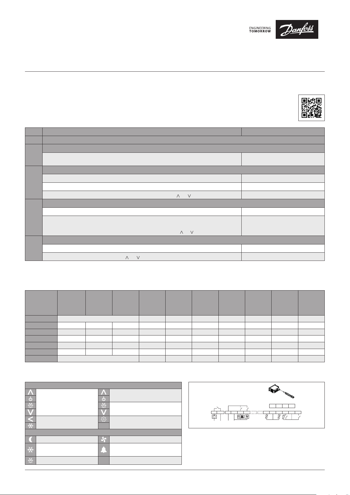
Quick Set-up
STEP Action Screen Display
STEP 1 Wire control, to include power and sensors
Power up control
STEP 2
Energize control
Enter Quick Configuration Menu and Select app
Press ”<” for more than three seconds within one minute of power up to enter Quick Configuration Menu. o61 appears on screen
STEP 3
Press “set” while o61 is on screen AP0 flashes on screen
Select appropriate app using App Selection section below by pressing “ ” or “ ”, then press “set”. o06 appears on screen
Select Sensor
Press “set” while o06 is on screen n10 flashes on screen
STEP 4
If using included sensor, leave default value “n10”. If using another sensor, select using Sensor Resistance
section on opposing page or cycle through steps 2 – 4 changing the sensor type until the temperature reading
on the main screen is accurate. As above, cycle between options by pressing “ ” or “ ” and press “set” to save.
Set Temperature
STEP 5
From main screen, quickly press “set” (1 second). Current temp. setting appears on screen
Cycle to intended temperature by pressing “ ” or “ ” and press “set” to save. Screen returns to main screen
Control turns on, goes through start up,
then shows the current temperature reading
o06 appears on screen, then control resets
App Selection
Select application based on application and wiring configuration (i.e., refrigeration vs. freezing, and number of temperature sensors). The Typical Wiring
Configurations diagram on the reverse side of this document may be used to assist with selection. All parameters can be modified using the full menu.
Some parameters have min and max set points which may need to be changed for less common configurations.
Control
Application
Code
Application
Defrost
Type*
Defrost
Termination
Sensors
Default
Temp. [°F]
[r00]
Temp. Range
min. / max.
[r02/r03]
AP0 (Default) No preset application - full menu 2 36 -31 / 22 4 6 30 43
AP1 Refrigeration Natural Time 1 39 36 / 43 4 4 30 –
AP2 Refrigeration Electric Time 1 36 32 / 39 4 6 15 –
AP3 Freezing Electric Time 1 -11 -15 / -4 4 6 15 –
AP4 Refrigeration Electric Temp. 2 36 32 / 39 4 6 30 43
AP5 Freezing Electric Temp. 2 -11 -15 / -4 4 6 30 43
AP6 No preset application - simplified menu 2 36 -31 – 122 4 6 30 43
* Hot gas defrost is an option available in full menu (d01).
Key Functions and Display Icons
Key Functions
Press and hold at power up:
FACTORY RESET (“FAC” is
displayed)
Press for one second: BACK
Press and hold: PULL-DOWN
Display Icons
Night mode (Energy saving) Fan running
Compressor running (Flashes
in pull-down mode)
Defrost °C Unit (°C or °F)
SET
Press for one second: UP
Press and hold: ON / OFF
Press for one second: DOWN
Press and hold: DEFROST
Press for one second: TEMP. SETPOINT / OK
Press and hold: MENU
Active alarm
Connection Diagram
– Sair Control sensor
– S5 Defrost (evaporator) sensor
– SC Condenser sensor
– DI1 Digital input – configurable to the functions listed under
menu code o02
– DI2 Digital input – configurable to the functions listed under
menu code o37
© Danfoss | DCS (ADAP-KOOL®) | 2018-11
[°F]
Default Dif.
[°F] [r01]
DO1
12
3L 4N 5678
~~~~
Power supply
DO2 DO3
Defrost
Interval
[hrs]
[d03]
910
SairS5Sc/DI1 DI2
Max.
Defrost
Time [mins]
[d04]
Pr
GND TX RX +5V
15 16 17 18
GND GND
11 12 13 14
Defrost
Termination
Temp. [°F]
[d02]
DKRCE.PD.RL0.A3.02 | 1
Page 2
Quick Start Guide, ERC 213
(Control
Sensor)
115 V AC
230 V AC
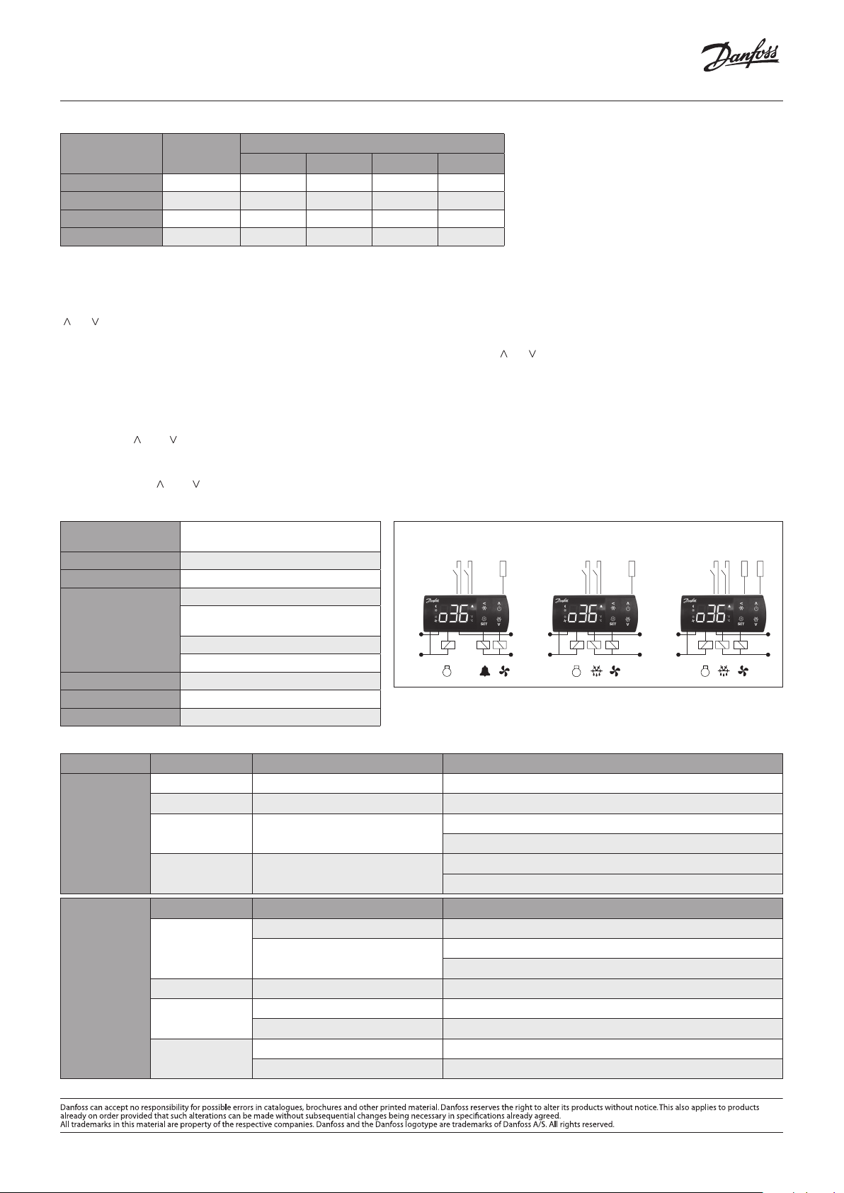
ERC 213 - APP 1 ERC 213 - APP 2-3 ERC 213 - APP 4-5
Sensor Resistance: Using an ohmmeter, you can measure resistance of a sensor to identify sensor type or to troubleshoot a potentially faulty sensor.
Sensor Type Code
PTC Ptc 690 761 807 980
PTC 1000 Pt1 931 974 1000 1093
NTC 10000 * n10 70317 40411 29481 10459
NTC 5000 n5 42664 23110 16325 5251
* Included in kit
Resistance [ohm] at Temperature [°F]
0 20 32 75
Common Functions
Adjust Temperature Set Point
From main screen, quickly press “set” (one second). The current temperature setting will appear on screen. Cycle to intended temperature by pressing
“^” or “^” and press “set” to save. The display will return to the main screen.
Adjust Differential
From main screen, press “set” for more than three seconds. Cycle to “r--” submenu by pressing “ ” or “ ” and press “set.” Cycle to “r01” and press “set.” Cycle to
preferred differential setting, and press “set” to save. “r01” will appear on screen. Press “<” twice to return to main screen.
Manual Defrost
From main screen, press defrost for more than three seconds to initiate defrost. The DEFROST icon is shown during defrost. Press defrost key for at least
three seconds to stop manual defrost.
Factory Reset
Press and hold “ ” and “ ” simultaneously at power up.
Unlock Keypad
After 5 minutes of no activity, the keypad will lock if P76 = yes (by default it is set to no). When the keypad is locked any key press shows “LoC”
in the display. Press “ ” and “ ” simultaneously for three seconds to unlock the keyboard. “unl” is displayed for three seconds.
Technical Specifications
Power Supply
Inputs 4 total; 2 analog, 1 analog / digital, 1 digital
080G3411 115V AC 50/60 HZ;
080G3412 230V AC 50/60 Hz
Typical Wiring Configurations
Sair
(Control Sensor)
DI1DI2
DI1DI2
Sair
(Control Sensor)
Sensor Included in Kit NTC 10000
D01 Compressor Relay
115 V (080G3268): 16 FLA / 72 LRA
Output
230 V (080G3269): 10 FLA / 60 LRA
D02 Defrost Relay and / D03 Fan Relay
8A, 2 FLA, 12 LRA
DO1
DO2 DO3 DO1 DO3DO2
115 V AC
230 V AC
Operating Conditions 14 – 131 °F
Storage Conditions -40 – 158 °F
Approvals UL Recognized / NSF
Troubleshooting
Power Supply Code Description Remedy (applicable parameter code in parenthesis)
A01 High temperature alarm Bring down temperature or increase high limit alarm limit (A13)
A02 Low temperature alarm Increase temperature or low temperature alarm limit (A14)
Common Alarm /
Error Codes
E27 Defrost sensor error
E29 Air temperature sensor error
Problem Likely Cause Remedy (applicable parameter number in parenthesis)
Waiting for compressor delay timer
Compressor does
not start
Defrost in progress
Common
Problems /
Resolution
Need additional help with programming, parameters, or error codes? Download Danfoss’ Koolcode app.
Defrost does not start
Wrong temperature
is displayed
Evaporator icing
Controller in pull down mode Check pull-down duration (r96)
Wrong type of sensor selected Verify that correct sensor type is selected (o06)
Sensor installed into incorrect terminals Verify that control sensor is wired into terminals 9 and 10 – 8 is not used
Defrost interval too long Reduce defrost interval (d03)
Defrost time too short Increase max. defrost time (d04)
Verify that defrost sensor is wired into terminals 10 and 11
Verify that correct sensor type is selected (o06)
Verify that control sensor is wired into terminals 9 and 10 – 8 is not used
Verify that correct sensor type is selected
Check compressor minimum off time (
CO2)
Check defrost interval (d03)
Check defrost on demand (temp. initiated defrost) (d19)
115 V AC
230 V AC
DI1DI2
DO1DO3DO2
S5
(Defrost)
Sair
2 | DKRCE.PD.RL0.A3.02
© Danfoss | DCS (ADAP-KOOL®) | 2018-11
Page 3

Quick Start Guide, ERC 213
Parameter sheet
Parameter Name Menu Code Unit Min. Value Max. Value Default Value Value
Predefined applications o61 – – – App0 App0
Sensor type o06 – – – n10 n10
Temperature Setpoint r00 °C -100 200 2 2
Differential r01 K 0.1 20 2 2.7
Min. set point limit r02 °C -100 200 -35 -35
Max. set point limit r03 °C -100 200 50 50
Display offset r04 K -10 10 0 0
Display Unit r05 – – – °C °F
Calibration of Sair r09 K -20 20 0 0
Night Set back r13 K -50 50 0 0
Offset reference displacement r40 °C -50 20 0 0
Pull down duration r96 min.. 0 960 0 0
Pull down temp limit r97 °C -100 200 0 0
Alarm delay - Normal conditions A03 min. 0 240 30 30
Alarm delay - pulldown / startup / def
High temp alarm A13 °C -100 200 8 8
Low temp alarm A14 °C -100 200 -30 -30
DI1 delay A27 min. 0 240 30 30
DI2 delay A28 min. 0 240 30 30
Condenser High temp alarm A37 °C 0 200 80 80
Condenser High block limit A54 °C 0 200 85 85
Voltage protection A72 – – – No No
Min. cut-in voltage A73 V 0 270 0 0
Min. cut-out voltage A74 V 0 270 0 0
Max. voltage A75 V 0 270 270 270
Defrost Method d01 – – – Electric Electric
Defrost stop temperature d02 °C 0 50 6 6.5
Defrost Interval d03 hour 0 240 8 6
Max. defrost Time d04 min. 0 480 30 30
Defrost delay at power up d05 min. 0 240 0 0
Drip delay d06 min. 0 60 0 0
Fan delay after defrost d07 min. 0 60 0 0
Fan start temp after defrost d08 °C -50 0 -5 -5
Fan ON during defrost d09 – – – On On
Defrost stop sensor d10 – – – None None
Comp accumulated runtime d18 hour 0 96 0 0
Defrost on demand d19 K 0 20 20 20
Defrost delay after pulldown d30 min. 0 960 0 0
Fan at compressor cutout F01 – – – FFC FAo
Fan stop evaporator temp F04 °C -50 50 50 50
Fan ON time F07 min. 0 15 2 2
Fan OFF time F08 min. 0 15 2 2
A12 min. 0 240 60 60
© Danfoss | DCS (ADAP-KOOL®) | 2018-11
DKRCE.PD.RL0.A3.02 | 3
Page 4

Quick Start Guide, ERC 213
Parameter Name Menu Code Unit M in. Value Max. Value Default Value Value
Compressor min. ON time C01 min. 0 30 0 0
Compressor min. OFF time C02 min. 0 30 2 2
Comp OFF delay at open door C04 min. 0 15 0 0
Zero crossing C70 – – – yes yes
Delay of outputs at startup o01 sec 0 600 5 5
DI1 configuration o02 – – – Off Off
Serial address o03 – 0 247 0 0
Password o05 – 0 999 0 0
Display Resolution o15 – – – 0.1 1
Relay 1 counter o23 – – – – 0
Relay 2 counter o24 – – – – 0
Relay 3 counter o25 – – – – 0
DI2 configuration o37 – – – Off Off
Display during defrost o91 – – – -d- -d-
DO2 Config o71 – – – def def
DI1 polarity P73 – – – no no
DI2 polarity P74 – – – no no
Invert alarm relay P75 – – – Normal Normal
Keyboard lock P76 – – – No No
Main switch r12 – – – Off On
Controller status u00 – – – S25 S20
Air temperature (Sair) u01 °C – – – 321
Present regulation reference u02 – – – 0
Evaporator temperature (S5) u09 °C – – – 0
DI1 status u10 – – – Off Off
Night mode u13 – – – Off Off
DI2 status u37 – – – Off Off
Condenser temperature (Sc) U09 – – – 0
Compressor relay status u58 – – – Off Off
Fan relay status u59 – – – Off On
Defrost relay status u60 – – – Off Off
Firmware version u80 – – – – 4.16
Database version – – – – – 4.02
Order No Low – – – – – 3502
Air temperature sensor(Sair) error E29 – – – Off On
Defrost sensor (S5) error E27 – – – Off Off
Condensor sensor(Sc) error E30 – – – Off Off
High temperature alarm A01 – – – Off Off
Low temperature alarm A02 – – – Off Off
High voltage alarm A99 – – – Off Off
Low voltage alarm AA1 – – – Off Off
High condenser temperature alarm A61 0 – – Off Off
Door alarm A04 0 – – Off Off
DI external alarm A15 0 – – Off Off
4 | DKRCE.PD.RL0.A3.02
© Danfoss | DCS (ADAP-KOOL®) | 2018-11
 Loading...