

Page 1
Installation Guide
ERC 211
Digital controller for refrigeration and defrost, 1 relay.
Page 2
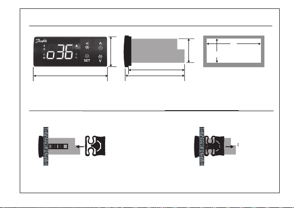
Dimensions (mm) and Mounting
83
66
Rear mounting (lock with clips)
Drilling template
Mounting Dismounting
61.2
28
D
36
71
29
| 2 DKRCE.PI.RL0 .F7.MLInstallation Guide | ERC 211
Page 3
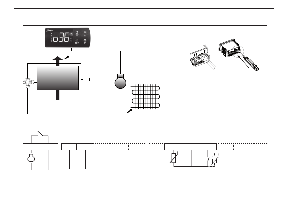
Electrical Connections
DG
31
Sair
Quick progr amming tool: EKA 183B
DO1
DO1
12
3L 4N 567891011121
~~~~
Power supply
(according to the product code number)
Sc
Connectors:
Max. Torque = 0.4 Nm
GN
SairSc/DI1
ND
4
| 3DKRCE.PI.RL0 .F7.ML Installation Guide | ERC 211
Page 4

The ERC 211 is a smart, multipurpose integrated refrigeration controller with temperature and defrost
management, available with 1 relay.
This controller is for Operating temperature sensing control, suitable for refrigeration and heating
applications.
ENGLISH
Incorporated control has been designed to fulfil today’s requirements for commercial refrigeration
applications.
1 - Technical Highlights
y Ease of use: Four buttons, easy menu structure, pre-installed application solutions ensure superior usability.
y Simple installation:
High Effect 16 A relay enable direct connection of heavy loads without use of intermediate relay: up to 2 hp
compressors depending on its power factor and motor efficiency (greater than 0.65 for 230 V and greater than 0.85
for 115 V).
A wide range of compatible types of sensors and screw connection terminals ensure highly flexible installation.
y Unit protection: Special software features like compressor protection from fluctuation in the power supply or from
high condensing temperature ensure the safe operation of the unit.
y Energy efficiency: Defrost on demand, day/night mode and smart evaporator fan management ensure energy
efficiency.
| 4 DKRCE.PI.RL0 .F7.MLInstallation Guide | ERC 211
Page 5
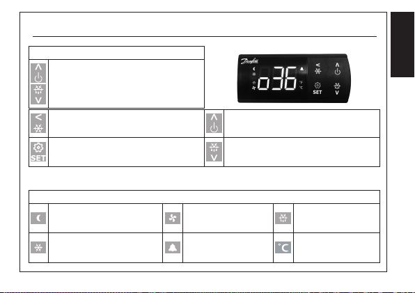
2 - User Interface
Key Function
Press and hold at power up:
FACTORY RESET
(“FAC” is displayed)
ENGLISH
Press for one second: BACK
Press and hold: PULL-DOWN
Press for one second:
TEMPERATURE SETPOINT/OK
Press and hold: MENU
Display Icons
Night mode
(Energy saving)
Compressor running
Flashes in pull-down mode
Press for one second: UP
Press and hold: ON/OFF
Press for one second: DOWN
Press and hold: DEFROST
Fan running Defrost
Active alarm Unit (°C or °F)
| 5DKRCE.PI.RL0 .F7.ML Installation Guide | ERC 211
Page 6
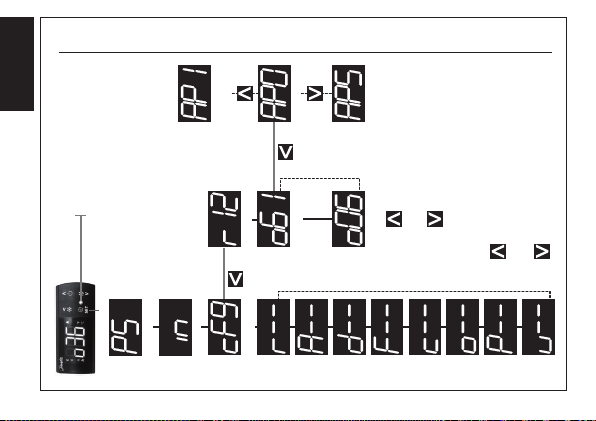
3 - Quick Configuration at Powe r Up
y STEP 1: Power on
y STEP 2: Select the quick configuration menu
Within 30 seconds of power on, press “<” BACK for 3 seconds.
ENGLISH
The main switch “r12” is automatically set to OFF.
y STEP 3: Select pre-installed application “o61”
The display automatically shows the application selection parameter “o61”.
Press SET to select the pre-installed application.
The display shows the default value (eg. “AP0” flashing).
Choose the application type by pressing UP/DOWN and press SET to confirm.
The controller presets parameter values according to the selected application and does not hide relevant parameters.
Tip: you can easily move from AP0 to AP5, and thus select the simplified list of parameters, by pressing the UP key
(circular list).
App Description
App 0 None (no preset application)
App 1 Medium temperature (4 – 20 °C), without defrost
App 2 Medium temperature (2 – 6 °C), with timed natural defrost
App 3 Medium temperature (2 – 6 °C), with natural defrost stop on air temperature
App 4 Heating Thermostat (20 – 60 °C)
App 5 None (no preset application) with simplified parameter list
| 6 DKRCE.PI.RL0 .F7.MLInstallation Guide | ERC 211
Page 7

Quick Configuration at Powe r Up
y STEP 4: Select sensor type “o06”
The display automatically shows sensor selection parameter “o06”.
Press SET to select the sensor type.
The display shows the default value (eg. “n10” flashing).
Choose sensor type by pressing UP/DOWN (n5=NTC 5 K, n10=NTC 10 K, Ptc=PTC, Pt1=Pt1000) and press SET
to confirm.
NOTE: All sensors must be the same type.
ENGLISH
| 7DKRCE.PI.RL0 .F7.ML Installation Guide | ERC 211
Page 8

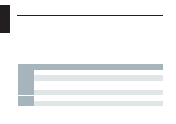
4 - Menu structure
1) Parameter groups
Password (if enabled)
Status input
Configuration
ENGLISH
1-2-3-4-5
3) Value
Application
SET: press for 3 seconds to access
status, setup and service
2) Parameter name
SET
| 8 DKRCE.PI.RL0 .F7.MLInstallation Guide | ERC 211
Application 0
SET
Application
Main switch
5-4-3-2-1
Application
Sensor type
Scroll through the
parameter names
Scroll through the
parameter groups
Page 9

5 - Quick Configuration via “cFg ” Menu
y Press SET for three seconds to access the parameters groups.
y Select “CFg” menu and press SET to enter. The first menu “r12” (main switch) is displayed.
y Switch OFF main switch (r12=0) for changing the pre-installed application.
y Press UP/DOWN to scroll through the parameter list.
y Configure the “o61” parameter to select a pre-installed application
- Press SET to access the “o61” parameter.
- Press UP/DOWN to select an application (AP0= no application selected).
- Press SET to confirm, “o61” is displayed.
y Continue to set the next parameters (“o06” sensor type) in the “cFg” menu.
ENGLISH
| 9DKRCE.PI.RL0 .F7.ML Installation Guide | ERC 211
Page 10
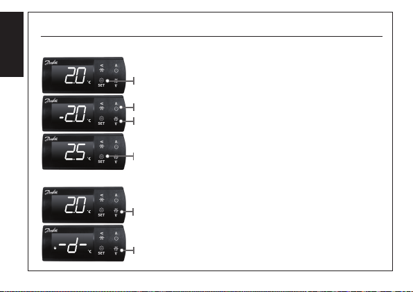
6 - Basic op eration
Adjust the setpoint temperature
ENGLISH
(short press) SET: adjust setpoint temperature.
UP/DOWN: change the temperature setpoint
(in setting mode the setpoint flashes).
SET: save the temperature setpoint.
Initiate a manual defrost
DEFROST: press for 3 seconds to initiate a defsost.
DEFROST: press for 3 seconds to stop manual defrost.
The DEFROST icon is shown during defrost.
| 10 DKRCE.PI.RL0 .F7.MLInstallation Guide | ERC 211
Page 11

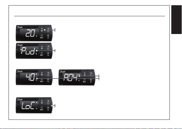
Basic op eration - 02
Initiate a pull down
View an active alarm
PULL DOWN: press for 3 seconds to initiate pull down.
“Pud”: is shown for 3 seconds to indicate pull down.
The PULL DOWN icon flashes during pull down.
PULL DOWN: press for 3 seconds to stop pull down.
Temperature and alarm codes
alternate flashes until the alarm
is resolved. The alarm bell is shown.
ENGLISH
Unlock keyboard
- After 5 minutes of no activity, the keypad is locked (if P76=yes).
- When the keypad is locked any button press shows “LoC” in the display.
- Press UP and DOWN buttons simultaneously for 3 seconds
to unlock the keyboard. “unl” is displayed for 3 seconds.
| 11DKRCE.PI.RL0 .F7.ML Installation Guide | ERC 211
Page 12

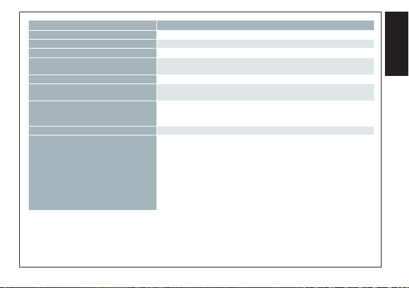
7 - Technical Data
FEATURES DESCRIPTION
Purpose of control
ENGLISH
Construction of control Incorporated control
Power supply
Rated power Less than 0.7 W
Inputs
Allowed sensors types
Sensors included in Kit Solution NTC 10000 Ohm at 25 °C, cable length = 1.5 m
Accuracy
Type of action 1B (relay)
Output
| 12 DKRCE.PI.RL0 .F7.MLInstallation Guide | ERC 211
Operating temperature sensing control suitable for incorporation into
commercial air-conditioning and refrigeration applications
115 V AC / 230 V AC 50/60 Hz, galvanic isolated low voltage regulated
power supply
Sensor inputs, Digital inputs, Programming key
Connected to SELV limited energy <15 W
NTC 5000 Ohm at 25 °C, (Beta value=3980 at 25/100 °C - e.g. EKS 211)
NTC 10000 Ohm at 25 °C, (Beta value=3435 at 25/85 °C - e.g. EKS 221)
PTC 990 Ohm at 25 °C, (e.g. EKS 111)
Pt1000, (e.g. AKS 11, AKS 12, AKS 21)
Measuring range:
-40 – 105 °C (-40 – 221 °F)
Controller accuracy:
+/-1 K below -35 °C, +/- 0.5 K between -35 – 25 °C,
+/-1 K above 25 °C
DO1 Compressor relay:
16 A, 16 (16) A, EN 60730-1
10 FLA/60 LRA at 230 V, UL60730-1
16 FLA/72 LRA at 115 V, UL60730-1
Page 13
FEATURES DESCRIPTION
Display LED display, 3 digits, decimal point and multi-function icons, °C + °F scale
Operating conditions -10 – 55 °C (14 – 131 °F), 90% Rh
Storage conditions -40 – 70 °C (-40 – 158 °F), 90% Rh
Protection
Environmental Pollution degree II, non-condensing
Overvoltage category
Resistance to heat and fire
EMC category Category I
Approvals
Front : IP65 (Gasket integrated)
Rear: IP00
II - 230 V supply version - (ENEC, UL recognized)
III - 115 V supply version - (UL recognized)
Category D (UL94-V0)
Temperature for ball pressure test statement “According to Annex G”
(EN 60730-1)
UL recognition (US & Canada) (UL 60730-1)
ENEC (EN 60730-1)
CQC
CE (LVD & EMC Directive)
EAC (GHOST)
NSF
ROHS2.0
HACCP temperature monitoring in compliance with EN134785 Class I,
when used with AKS 12 sensor
ENGLISH
| 13DKRCE.PI.RL0 .F7.ML Installation Guide | ERC 211
Page 14
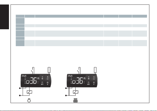
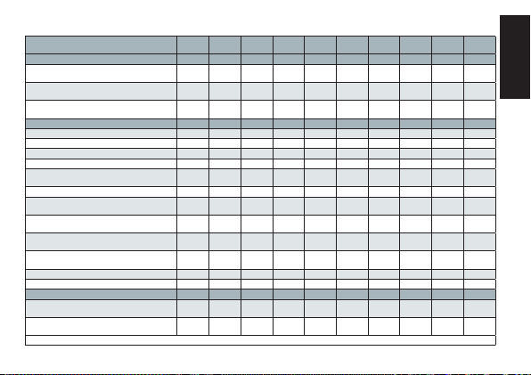
8 - Predefined Application Setup
APP 1/2/3 APP 4
App Mode Description Temp. Def. type Def. end
Cooling/
App 0
ENGLISH
App 1 Cooling Medium temperature without defrost (4 – 20 °C) None None
App 2 Cooling Medium temperature with timed natural defrost (2 – 6 °C) Natural Time
App 3 Cooling
App 4 Heating Heating Thermostat (20 – 60 °C) None None
App 5
None (no preset application)
Heating
Medium temperature with natural defrost stop on air
temperature
Cooling/
None (no preset application) with simplified parameter list
Heating
(2 – 6 °C) Natural
Air
temperature
230
V AC
DO1
| 14 DKRCE.PI.RL0 .F7.MLInstallation Guide | ERC 211
SairDI1 SairDI1
230
V AC
DO1
Page 15
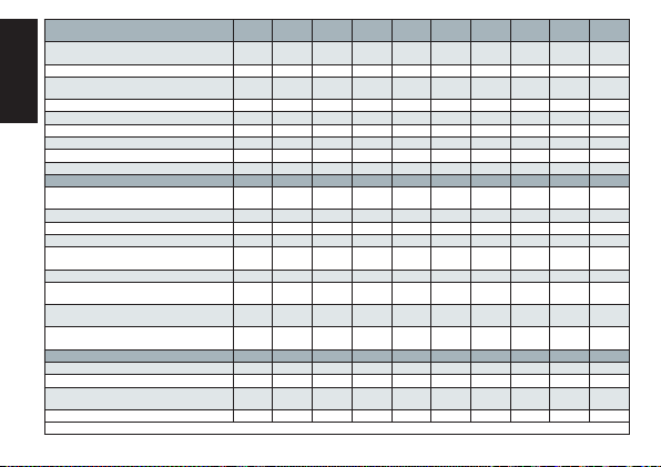
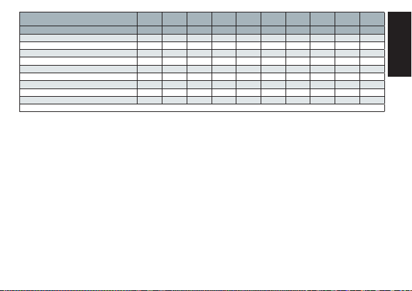
9 - Paramet er List
Parameter name - ERC 211 Code Min Max Unit
Configuration cFg
Main switch
-1=service, 0=OFF, 1=ON
Predefined applications
AP0, AP1, AP2, AP3, AP4, AP5
Sensor type selection
n5=NTC 5 K, n10=NTC 10 K, Ptc=PTC, Pt1=Pt1000
Reference/thermostat r--
Temperature setpoint r00 -100.0 200.0 C/F 2.0 8.0 4.0 4.0 40.0 2.0
Differential r01 0.1 20.0 K 2.0 2.0 2.0 2.0 2.0 2.0
Min set point limitation r02 -100.0 200.0 C/F -35.0 4.0 2.0 2.0 20.0 -35.0
Max set point limitation r03 -100.0 200.0 C/F 50.0 20.0 6.0 6.0 60.0 50.0
Display offset
(correction value in display temperature)
Display unit (°C/°F) r05 -C -F -C -C -C -C -C -C
Calibration of Sair
(offset for air temperature calibration)
Main switch
-1=service, 0=OFF, 1=ON
Night set back
(offset temperature during night mode)
Thermostat reference displacement
(offset temperature)
Pull-down duration r96 0 960 min 0 - 0 0 - -
Pull-down limit temperature r97 -100.0 200.0 C/F 0.0 - 0.0 0.0 - -
Alarm A--
Delay for temperature alarm
during normal conditions
Delay for temperature alarm
during pull-down/start-up/defrost
Note: hidden parameters are greyed out
r12 -1 1 1 1 1 1 1 1
o61 AP0 AP5 AP0 AP1 AP2 AP3 AP4 AP5
o06 n5 Pt1 n10 n10 n10 n10 n10 n10
r04 -10.0 10.0 K 0.0 0.0 0.0 0.0 0.0 0.0
r09 -20.0 20.0 K 0.0 0.0 0.0 0.0 0.0 -
r12 -1 1 1 1 1 1 1 -
r13 -50.0 50.0 K 0.0 0.0 0.0 0.0 0.0 0.0
r40 -50.0 50.0 K 0.0 0.0 0.0 0.0 0.0 -
A03 0 240 min 30 45 45 45 30 30
A12 0 240 min 60 60 90 90 60 60
App. 0
App. 1 App. 2 App. 3 App. 4 App. 5
(Def.)
ENGLISH
| 15DKRCE.PI.RL0 .F7.ML Installation Guide | ERC 211
Page 16
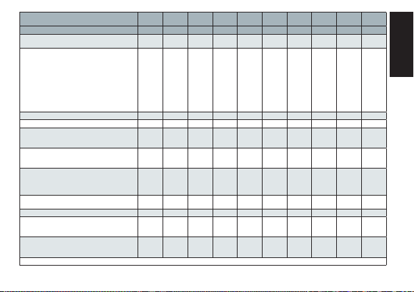
Parameter name - ERC 211 Code Min Max Unit
High temperature alarm limit
(Cabinet/room)
Low temperature alarm limit A14 -100.0 200.0 C/F -30.0 0.0 0.0 0.0 10 -30.0
DI1 delay
(time delay for selected DI1 function)
ENGLISH
Condenser high alarm limit A37 0 200 C/F 80 80 80 80 - -
Condenser high block limit A54 0 200 C/F 85 85 85 85 - -
Voltage protection enable A72 no yES no no no no no no
Minimum cut-in voltage A73 0 270 V 0 0 0 0 0 0
Minimum cut-out voltage A74 0 270 V 0 0 0 0 0 0
Maximum voltage A75 0 270 V 270 270 270 270 270 270
Defrost d--
Defrost method
no=no defrost, nAt=natural
Defrost stop temperature d02 0.0 50.0 C/F 6.0 - - 8 - 6.0
Defrost interval d03 0 240 hours 8 - 6 6 - 8
Max defrost time d04 0 480 min 30 - 45 60 - 30
Defrost delay at power up
(or DI signal)
Drip delay d06 0 60 min 0 - 0 0 - -
Defrost stop sensor
configuration, non=time, Air=Sair (air temperature)
Compressor accumulated
runtime to start defrost, 0=OFF
Defrost delay after pull-down
0=OFF
Compressor c--
Compressor minimum ON time C01 0 30 min 0 0 0 0 0 0.0
Compressor minimum OFF time C02 0 30 min 2 2 2 2 2 2.0
Compressor OFF delay
at door open
Zero crossing selection C70 no yES yES yES yES yES yES yES
Note: hidden parameters are greyed out
A13 -100.0 200.0 C/F 8.0 16 10 10 80 8.0
A27 0 240 min 30 30 30 30 30 30
d01 no n At no no nAt nAt no no
d05 0 240.0 min 0 - 0 0 - -
d10 non Air non - non Air - non
d18 0 96 hours 0 - 0 0 - -
d30 0 960 min 0 - 0 0 - -
C04 0 15 min 0 0 0 0 0 1
App. 0
App. 1 App. 2 App. 3 App. 4 App. 5
(Def.)
| 16 DKRCE.PI.RL0 .F7.MLInstallation Guide | ERC 211
Page 17
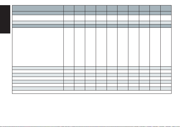
Parameter name - ERC 211 Code Min Max Unit
Others o--
Delay of outputs
at startup
DI1 configuration
oFF=not used,
Sdc=status display output,
doo=door alarm with resumption,
doA=door alarm without resumption,
SCH = main switch, nig=day/ night mode,
rFd=reference displacement,
EAL=external alarm,
dEF=defrost, Pud=pull-down,
Sc=condenser sensor
Serial address o03 0 247 0 0 0 0 0 -
Password o05 no 999 no no no no no no
Sensor type selection
n5=NTC 5 K, n10=NTC 10 K,
Ptc=PTC, Pt1=Pt1000
Cooling/heating
rE=refrigeration (cooling)
Ht=heating
Display resolution
0.1=steps of 0.1 °C
0.5=steps of 0.5 °C,
1.0=steps of 1.0 °C
Relay 1 counter
(1 count=100 cycles of operation)
Predefined applications o61 AP0 AP5 AP0 AP1 AP2 AP3 AP4 -
Save settings as factory
WARNING: the earlier factory settings are
overwritten
Display at defrost
Air=actual air temperature, FrE=freezed
temperature, -d-="-d-" is displayed
Note: hidden parameters are greyed out
o01 0 600 min 5 5 5 5 5 5
o02 oFF Sc oFF oFF oFF oFF oFF oFF
o06 n5 Pt1 n10 n10 n10 n10 n10 -
o07 rE Ht rE rE rE rE Ht rE
o15 0.1 1.0 0.1 0.1 0.1 0.1 0.1 0.1
o23 0 999 0 0 0 0 0 -
o67 no yES no no no no no -
o91 Air -d- -d- - -d- -d- - - d-
App. 0
App. 1 App. 2 App. 3 App. 4 App. 5
(Def.)
ENGLISH
| 17DKRCE.PI.RL0 .F7.ML Installation Guide | ERC 211
Page 18
Parameter name - ERC 211 Code Min Max Unit
Polarity P--
DI1 input polarity
nc=normally closed, no=normally open
Keyboard lock enable P76 no yES no no no no no -
Readouts u--
ENGLISH
Controller status
S0=cooling ON/Heating ON,
S2=wait for compressor ON time to elapse,
S3=wait for compressor OFF time to elapserestart time, S4=drip OFF delay after defrost,
S10=cooling stop,
S11=cooling stopped by thermostat/heating
OFF, S14=defrosting state,
S15=fan delay state after defrost,
S17=door open (DI input),
S20=emergency cooling,
S25=manual control of outputs,
S30=continous cycle/Pull-down,
S32=delay of outputs at power up
Air temperature (Sair) u01 -100.0 200.0 C/F ---
Read the present regulation reference u02 -100.0 200.0 C/F ---
DI1 input u10 oFF on ---
Status of night operation u13 oFF on ---
Condenser temperature (Sc) U09 -100.0 200.0 C/F ---
Compressor relay status u58 oFF on ---
Firmware version readout u80 000 999 ---
Note: hidden parameters are greyed out
P73 nc no no no no no no no
u00 S0 S32 --
App. 0
App. 1 App. 2 App. 3 App. 4 App. 5
(Def.)
| 18 DKRCE.PI.RL0 .F7.MLInstallation Guide | ERC 211
Page 19
Parameter name - ERC 211 Code Min Max Unit
Alarm status
Sair air temperature sensor error E29
High temperature alarm A01
Low temperature alarm A02
High voltage alarm A99
Low voltage alarm AA1
Condenser alarm A61
Door alarm A04
Standby alarm A45
DI external alarm A15
Note: hidden parameters are greyed out
App. 0
App. 1 App. 2 App. 3 App. 4 App. 5
(Def.)
ENGLISH
| 19DKRCE.PI.RL0 .F7.ML Installation Guide | ERC 211
Page 20

Safety Standards
Check if the supply voltage is correct before connecting the instrument.
Do not expose to water or moisture: use the controller only within the operating limits avoiding sudden temperature
changes with high atmospheric humidity to prevent the formation of condensation.
ENGLISH
Disposal of the Product
The appliance (or the product) must be disposed of in accordance with the local waste disposal legislation.
EU Design Registration
002566703-0001
Danfoss can accept no responsibility for possible errors in catalogues, brochures and other printed material. Danfoss reserves the
right to alter its products without notice. This also applies to products already on order provided that such alterations can be made
without subsequent changes being necessary in specifications already agreed. All trademarks in this material are property of the
property of the respective companies. Danfoss and Danfoss logotype are trademarks of Danfoss A/S. All rights reserved.
| 20 DKRCE.PI.RL0 .F7.MLInstallation Guide | ERC 211
Page 21

Notes
ENGLISH
| 21DKRCE.PI.RL0 .F7.ML Installation Guide | ERC 211
Page 22

L’ERC 211 est un système intégré de contrôle de la réfrigération intelligent et multifonction, avec gestion
de la température et du dégivrage, disponible avec 1 relais.
Ce régulateur sert de commande assujettie à la température de fonctionnement, qui convient aux
applications de réfrigération et de chauffage.
La commande intégrée a été conçue pour répondre aux besoins actuels des applications de réfrigération
FRANÇAIS
commerciales.
1 - Principales caractéristiques techniques
y Simplicité d’utilisation : quatre touches, une structure de menus facile à utiliser et des applications pré-installées
garantissent une maniabilité supérieure.
y Installation simple : un relais hautes performances de 16 A permet la connexion directe de lourdes charges sans
utiliser des relai intermédiaires: jusqu’à 2 compresseurs en fonction de son facteur de puissance et de l’efficacité
moteur (supérieur à 0.65 pour 230 V et supérieur à 0.85 pour 115 V).
Une large gamme de types de sondes et de bornes avec raccord à vis compatibles offrent une grande flexibilité
pendant l’installation.
y Protection de l’unité : des fonctions logicielles spéciales comme la protection du compresseur contre les
fluctuations de l’alimentation électrique ou contre une température de condensation élevée garantissent le
fonctionnement de l’unité en toute sécurité.
y Rendement énergétique : le dégivrage à la demande, le mode jour/nuit et la gestion intelligente du ventilateur de
l’évaporateur garantissent le rendement énergétique.
| 22 DKRCE.PI.RL0 .F7.MLInstallation Guide | ERC 211
Page 23

2 - Interface utilisateur
Fonctionnement des touches
Pression prolongée à la mise sous tension:
RÉINITIALISATION D’USINE (“ FAC “ s’affiche)
FRANÇAIS
Pression brève : RETOUR
Pression prolongée : DIMINUTION
Pression brève :
POINT DE CONSIGNE DE TEMPÉRATURE/OK
Pression prolongée : MENU
Icônes de l’afficheur
Mode nuit
(économies d’énergie)
Compresseur en fonctionnement
(clignote en mode diminution)
Pression brève : HAUT
Pression prolongée : MARCHE/ARRÊT
Pression brève : BAS
Pression prolongée : DÉGIVRAGE
Ventilateur en
fonctionnement
Alarme active Unité (°C ou °F)
Dégivrage
| 23DKRCE.PI.RL0 .F7.ML Installation Guide | ERC 211
Page 24
3 - Configuration rapide à la mi se sous tension
y ÉTAPE 1 : Mettre sous tension
y ÉTAPE 2 : Sélectionner le menu de configuration rapide
Dans un délai de 30 secondes suivant la mise sous tension, appuyer sur “ < “ RETOUR pendant 3 secondes.
FRANÇAIS
Le sectionneur principal “r12” est automatique réglé sur OFF (Arrêt).
y ÉTAPE 3 : Sélectionner l’application pré-installée “ o61 “
L’écran affiche automatiquement le paramètre de sélection de l’application “ o61 “.
Appuyer sur SET pour sélectionner l’application pré-installée.
L’écran affiche la valeur par défaut (par ex. “ AP0 “ clignote).
Sélectionner le type d’application en appuyant sur HAUT/BAS et appuyer sur SET pour confirmer.
Le régulateur effectue le préréglage des valeurs de paramètre en fonction de l’application sélectionnée et masque les
paramètres non pertinents.
Astuce: vous pouvez aisément passer de AP0 à AP5, et donc sélectionner la liste simplifiée des paramètres, en pressant
la touche HAUT (liste circulaire).
App Description
App 0 Aucune (aucune application préréglée)
App 1 La température moyenne application (4 – 20 °C), sans dégivrage refroidissement
Moyennes applications de refroidissement de la température (2 – 6 °C) avec dégivrage naturel
App 2
chronométré
App 3 Applications à moyenne température (2 – 6 °C), avec arrêt de dégivrage naturel par la température de l’air
App 4 Thermostat de chauffage simple (20 – 60 °C)
App 5 Aucun (pas de présélection) avec la liste des paramètres simplifiés
| 24 DKRCE.PI.RL0 .F7.MLInstallation Guide | ERC 211
Page 25

Configuration rapide à la mise sous tension
y ÉTAPE 4 : Sélectionner un type de sonde “ o06 “
L’écran affiche automatiquement le paramètre de sélection de la sonde “ o06 “.
Appuyer sur SET pour sélectionner le type de sonde.
L’écran affiche la valeur par défaut (par ex. “ n10 “ clignote).
Sélectionner le type de sonde en appuyant sur HAUT/BAS (n5=NTC 5 K, n10=NTC 10 K, Ptc=PTC, Pt1=Pt1000) et
appuyer sur SET pour confirmer.
REMARQUE: toutes les sondes doivent être du même type.
FRANÇAIS
| 25DKRCE.PI.RL0 .F7.ML Installation Guide | ERC 211
Page 26
4 - Structure de me nus
1) Groupes de paramètres
Mot de passe (le cas échéant)
Entrée d’état
Configuration
FRANÇAIS
SET (Régler) : appuyer pendant
3 secondes pour accéder à l’état,
à l’installation et à l’entretien
| 26 DKRCE.PI.RL0 .F7.MLInstallation Guide | ERC 211
3) Valeur
1-2-3-4-5
Application
2) Nom du paramètre
SET
Application 0
SET
Application
Sectionneur principal
5-4-3-2-1
Application
Type de sonde
du paramètre
Faire défiler le nom
de paramètres
Faire défiler le groupe
Page 27

5 - Configuration rapide via l e menu “ cFg “
y Appuyer sur la touche SE T (Régler) pendant trois secondes pour accéder aux groupes de paramètres.
y S électionner le menu “ cFg “ et appuyer sur SET pour entrer dans le menu. Le premier menu “ r12 “
y (sec tionneur principal) s’affiche.
y Couper le sec tionneur principal (r12=0) pour modifier l’application pré-installée.
y Appuyer sur HAUT/BAS pour faire défiler la liste des paramètres.
y Configurer le paramètre “ o61 “ pour sélectionner une application pré-installée
- Appuyer sur SET pour accéder au paramètre “ o61 “.
- Appuyer sur HAUT/BAS pour sélectionner une application (AP0=pas d’application sélectionnée).
- Appuyer sur SET pour confirmer, “ o61 “ s’affiche.
y Continuer à régler les paramètres suivants (type de sonde “ o06 “) dans le menu “ cfg “.
FRANÇAIS
| 27DKRCE.PI.RL0 .F7.ML Installation Guide | ERC 211
Page 28

6 - Fonctionnement de base
Régler la température de consigne
FRANÇAIS
(pression brève) SET (Régler) : ajuster la température de consigne.
HAUT/BAS : modifier le point de consigne de température
(en mode réglage, le point de consigne clignote).
SET : enregistrer le point de consigne de température.
Lancer un dégivrage manuel
DEFROST (Dégivrage) : appuyer pendant 3 secondes pour lancer un dégivrage.
DEFROST : appuyer pendant 3 secondes pour arrêter le dégivrage manuel.
L’icône DEFROST s’affiche pendant le dégivrage.
| 28 DKRCE.PI.RL0 .F7.MLInstallation Guide | ERC 211
Page 29
pour déverrouiller le clavier. « unl » s’affiche pendant 3 secondes.
Fonctionnement de base - 02
Lancer une diminution
PULL DOWN (Diminution) :
appuyer pendant 3 secondes pour lancer une diminution.
« Pud » : s’affiche pendant 3 secondes pour indiquer la diminution.
L’icône PULL DOWN clignote pendant la diminution.
PULL DOWN : appuyer pendant 3 secondes pour arrêter la diminution.
FRANÇAIS
Acher une alarme active
Déverrouiller le clavier
- Au bout de 5 minutes d’inactivité, le clavier se verrouille (si P76=yes).
- Lorsque le clavier est verrouillé, la pression sur une touche entraîne
l’affichage de « LoC ».
- Appuyer simultanément sur la touche HAUT et BAS pendant 3 secondes
La température et les codes d’alarme
clignotent en alternance jusqu’à ce q
ue l’alarme soit résolue. La sonnette d’
alarme s’affiche.
| 29DKRCE.PI.RL0 .F7.ML Installation Guide | ERC 211
Page 30

7 - Données techniques
CARACTÉRISTIQUES DESCRIPTION
Objectif du contrôle
FRANÇAIS
Construction de la commande Commande intégrée
Alimentation électrique
Puissance nominale Inférieure à 0.7 W
Entrées
Type de sonde autorisé
Sonde inclus dans Solution Kit NTC 10000 Ohm à 25 °C, longueur du câble=1.5 m
Précision
Type d’action 1B (relais)
Sortie
| 30 DKRCE.PI.RL0 .F7.MLInstallation Guide | ERC 211
Commande assujettie à la température de fonctionnement destinée aux
applications de réfrigération et de climatisation commerciales.
Alimentation de 115 V c. a. /230 V c. a., 50/60 Hz, régulée à basse tension
et isolée galvaniquement
Entrées de capteur, Entrées numériques, Touches de programmation
Connecté à l’énergie limitée SELV < 15 W
NTC 5000 Ohm à 25 °C, (valeur Beta=3980 à 25/100 °C - ex. EKS 211)
NTC 10000 Ohm à 25 °C, (valeur Beta=3435 à 25/85 °C - ex. EKS 221)
PTC 990 Ohm à 25 °C, (ex. EKS 111)
Pt1000, (ex. AKS 11, AKS 12, AKS 21)
Plage de mesure :
-40 – 105 °C (-40 – 221 °F)
Précision du régulateur :
+/-1 K en dessous de -35 °C, +/- 0.5 K entre -35 et 25 °C,
+/-1 K au-dessus de 25 °C
Relais du compresseur DO1
16 A, 16 (16) A, EN 60730-1
10 FLA/ 60 LRA à 230 V, UL60730-1
16 FLA/ 72 LRA à 115 V, UL60730-1
Page 31

CARACTÉRISTIQUES DESCRIPTION
Affichage Écran LED 3 chiffres, point décimal et icônes multifonctions, valeurs °C/°F
Conditions de fonctionnement De -10 à 55 °C (de 14 à 131 °F), 90% HR
Conditions de stockage De -40 à 70 °C (de - 40 à 158 °F), 90% HR
Protection
Impact sur l’environnement Degré de pollution II, sans condensation
Catégorie de surtension
Résistance à l’incendie et à la chaleur
Catégorie D (UL94-V0) Catégorie I
Homologations
Avant : IP65 (garniture intégrée)
Arrière : IP00
II - version d’alimentation 230 V - (reconnu ENEC, UL)
III - version d’alimentation 115 V - (reconnu UL)
Catégorie D (UL94-V0)
Température pour test de pression à la bille, indication « Conformément à
l’Annexe G »
(EN 60730-1)
UL reconaissance (US & Canada) (UL 60730-1)
ENEC (EN 60730-1)
CQC
CE (LVD & EMC Directive)
EAC (GHOST)
NSF
ROHS2.0
Surveillance de température HACCP en conformité avec EN134785 Classe I,
Lorsque l’on utilise des sondes AKS 12
FRANÇAIS
| 31DKRCE.PI.RL0 .F7.ML Installation Guide | ERC 211
Page 32

8 - Installation de l’application prédéfinie
APP 1/2/3 APP 4
App Mode Description Temp. Type déf. Fin déf.
Refrodis./
App 0
FRANÇAIS
App 1 Refrodis.
App 2 Refrodis.
App 3 Refrodis.
App 4 Chauff. Thermostat de chauffage simple (20 – 60 °C) Aucun Aucun
App 5
Aucune (aucune application préréglée)
Chauff.
La température moyenne application sans dégivrage
refroidissement
Moyennes applications de refroidissement de la température
avec dégivrage naturel chronométré
Applications à moyenne température avec arrêt de dégivrage
naturel par la température de l’air
Refrodis./
Aucun (pas de présélection) avec la liste des paramètres simplifiés
Chauff.
(4 – 20 °C) Aucun Aucun
(2 – 6 °C) Naturel Naturel
(2 – 6 °C) Naturel
Température
de l’air
230
V AC
DO1
| 32 DKRCE.PI.RL0 .F7.MLInstallation Guide | ERC 211
SairDI1 SairDI1
230
V AC
DO1
Page 33

9 -Liste des param ètres
Nom du paramètre - ERC 211 Code Min. Max. Unité
Configuration cFg
Sectionneur principal
-1=entretien, 0=arrêt, 1=marche
Applications prédéfinies
AP0, AP1, AP2, AP3, AP4, AP5
Sélection du type de sonde
n5=NTC 5 K, n10=NTC 10 K,
Ptc=PTC, Pt1=Pt1000
Référence/Thermostat r--
Point de consigne de la température r00 -100.0 200.0 C/F 2.0 8.0 4.0 4.0 40.0 2.0
Différentiel r01 0.1 20.0 K 2.0 2.0 2.0 2.0 2.0 2.0
Limite min. du point de consigne r02 -100.0 200.0 C/F -35.0 4.0 2.0 2.0 20.0 -35.0
Limite max. du point de consigne r03 -100.0 200.0 C/F 50.0 20.0 6.0 6.0 60.0 50.0
Décalage d’affichage
(valeur de correction de la température
affichée)
Afficheur (°C/°F) r05 -C -F -C -C -C -C -C -C
Calibrage de Sair
(décalage de calibrage de la
température d’air)
Sectionneur principal
-1=entretien, 0=arrêt, 1=marche
Régime de nuit
(Décalage température en mode nuit)
Température de décalage
du déplacement de référence du thermostat
Durée de diminution r96 0 960 min 0 - 0 0 - -
Température limite de la diminution r97 -100.0 200.0 C/F 0.0 - 0.0 0.0 - -
Remarque : les paramètres cachés sont grisés
r12 -1 1 1 1 1 1 1 1
o61 AP0 AP5 AP0 AP1 AP2 AP3 AP4 AP5
o06 n5 Pt1 n10 n10 n10 n10 n10 n10
r04 -10.0 10.0 K 0.0 0.0 0.0 0.0 0.0 0.0
r09 -20.0 20.0 K 0.0 0.0 0.0 0.0 0.0 -
r12 -1 1 1 1 1 1 1 -
r13 -50.0 50.0 K 0.0 0.0 0.0 0.0 0.0 0.0
r40 -50.0 50.0 K 0.0 0.0 0.0 0.0 0.0 -
App. 0
App. 1 App. 2 App. 3 App. 4 App. 5
(Def.)
FRANÇAIS
| 33DKRCE.PI.RL0 .F7.ML Installation Guide | ERC 211
Page 34

Nom du paramètre - ERC 211 Code Min. Max. Unité
Alarme A--
Temporisation de l’alarme de température
pendant des conditions normales
Temporisation de l’alarme de température
pendant diminution/démarrage/dégivrage
FRANÇAIS
Seuil d’alarme de température élevée
(armoire/pièce)
Seuil d’alarme de basse température A14 -100.0 200.0 C/F -30.0 0.0 0.0 0.0 10 -30.0
Temporisation de DI1
(temporisation pour la fonction DI1
sélectionnée)
Seuil d’alarme maximum du condenseur A37 0 200 C/F 80 80 80 80 - -
Limite haute de blocage du condenseur A54 0 200 C/F 85 85 85 85 - -
Activer la protection de la tension A72 no yES no no no no no no
Tension d’enclenchement minimale A73 0 270 V 0 0 0 0 0 0
Tension de coupure minimale A74 0 270 V 0 0 0 0 0 0
Tension maximale A75 0 270 V 270 270 270 270 270 270
Dégivrage d--
Méthode de dégivrage
no=aucun dégivrage, nAt=naturel
Température d’arrêt du dégivrage d02 0.0 50.0 C/F 6.0 - - 8 - 6.0
Intervalle de dégivrage d03 0 240 heures 8 - 6 6 - 8
Temps de dégivrage max d04 0 480 min 30 - 45 60 - 30
Temporisation du dégivrage
à la mise sous tension (ou signal DI)
Temps d’égouttage d06 0 60 min 0 - 0 0 - -
Configuration de la sonde d’arrêt du dégivrage
non=heure, Air=Sair (température de l’air)
Temps d’exécution cumulé du compresseur
pour démarrer le dégivrage, 0=Arrêt
Temporisation du dégivrage
après diminution, 0=Arrêt
Remarque : les paramètres cachés sont grisés
A03 0 240 min 30 45 45 45 30 30
A12 0 240 min 60 60 90 90 60 60
A13 -100.0 200.0 C/F 8.0 16 10 10 80 8.0
A27 0 240 min 30 30 30 30 30 30
d01 no nAt no no nAt nAt no no
d05 0 240.0 min 0 - 0 0 - -
d10 non Air non - non Air - non
d18 0 96 heures 0 - 0 0 - -
d30 0 960 min 0 - 0 0 - -
App. 0
App. 1 App. 2 App. 3 App. 4 App. 5
(Def.)
| 34 DKRCE.PI.RL0 .F7.MLInstallation Guide | ERC 211
Page 35

Nom du paramètre - ERC 211 Code Min. Max. Unité
Compresseur c--
Durée minimum de marche
du compresseur
Durée de mise hors tension minimum
du compresseur
Temporisation d’arrêt du compresseur
à l’ouverture de la porte
Sélection du passage par zéro C70 no yES yES yES yES yES yES yES
Autres o--
Temporisation des sorties
à la mise en route
Configuration de DI1
oFF=non utilisé, Sdc=affichage d’état sortie,
doo=Alarme de porte avec reprise
doA=Alarme de porte sans reprise,
SCH=sectionneur principal,
nig=mode jour/nuit,
rFd=déplacement de référence,
EAL=alarme externe, dEF=dégivrage,
Pud=diminution,
Sc=sonde du condenseur
Adresse série o03 0 247 0 0 0 0 0 -
Mot de passe o05 no 999 no no no no no no
Sélection du type de sonde
n5=NTC 5 K, n10=NTC 10 K,
Ptc=PTC, Pt1=Pt1000
Climatisation/Chauffage
rE=réfrigération (refroidissement)
Ht=chauffage
Résolution de l’écran
0.1=incréments de 0.1 °C, 0.5=incréments de
0.5 °C, 1.0=incréments de 1.0 °C
Compteur du relais 1
(1 comptage=100 cycles de fonctionnement)
Remarque : les paramètres cachés sont grisés
C01 0 30 min 0 0 0 0 0 0.0
C02 0 30 min 2 2 2 2 2 2.0
C04 0 15 min 0 0 0 0 0 1
o01 0 600 min 5 5 5 5 5 5
o02 oFF Sc oFF oFF oFF oFF oFF oFF
o06 n5 Pt1 n10 n10 n10 n10 n10 -
o07 rE Ht rE rE rE rE Ht rE
o15 0.1 1.0 0.1 0.1 0.1 0.1 0.1 0.1
o23 0 999 0 0 0 0 0 -
App. 0
App. 1 App. 2 App. 3 App. 4 App. 5
(Def.)
FRANÇAIS
| 35DKRCE.PI.RL0 .F7.ML Installation Guide | ERC 211
Page 36

Nom du paramètre - ERC 211 Code Min. Max. Unité
Applications prédéfinies o61 AP0 AP5 AP0 AP1 AP2 AP3 AP4 -
Enregistrer les réglages par défaut
AVERTISSEMENT : les réglages d’usine
antérieurs sont écrasés
Affichage au dégivrage
Air=température réelle de l’air,
FRANÇAIS
FrE=température de gelée,
-d-=” -d- “ s’affiche
Polarité P--
Polarité d’entrée DI1
nc=normalement fermée,
no=normalement ouverte
Activer le verrouillage du clavier P76 no yES no no no no no -
Relevés u--
État du régulateur
S0=Refroidissement activé/Chauffage activé,
S2=attendre la fin du délai d’activation du
compresseur, S3=attendre la fin du délai d’activation
du compresseur-temps de redémarrage,
S4=temporisation d’arrêt de l’égouttage après
dégivrage, S10=refroidissement arrêté par l’arrêt du
sectionneur principal, S11=refroidissement arrêté
par le thermostat/arrêt du chauffage, S14=état
du dégivrage, S15=état de la temporisation du
ventilateur après dégivrage, S17=ouverture de la
porte (entrée DI), S20=refroidissement d’urgence,
S25=contrôle manuel des sorties,
S30=cycle continu/diminution S32=temporisation
des sorties à la mise en route
Température de l’air (Sair) u01 -100.0 200.0 C/F ---
Affichage de la référence de régulation
actuelle
Entrée DI1 u10 oFF on ---
État du régime de nuit u13 oFF on ---
Remarque : les paramètres cachés sont grisés
o67 no yES no no no no no -
o91 Air -d- -d- - -d- -d- - -d-
P73 nc no no no no no no no
u00 S0 S32 --
u02 -100.0 200.0 C/F ---
App. 0
App. 1 App. 2 App. 3 App. 4 App. 5
(Def.)
| 36 DKRCE.PI.RL0 .F7.MLInstallation Guide | ERC 211
Page 37

Nom du paramètre - ERC 211 Code Min. Max. Unité
Température du condenseur (Sc) U09 -100.0 200.0 C/F ---
État du relais du compresseur u58 oFF on ---
Relevé de la version du micrologiciel u80 000 999 ---
État d’alarme
Incident sur la sonde de température
de l’air Sair
Alarme de température élevée A01
Alarme de basse température A02
Alarme de haute tension A99
Alarme de basse tension AA1
Alarme du condenseur A61
Alarme porte A04
Alarme de veille A45
Alarme externe DI A15
Remarque : les paramètres cachés sont grisés
E29
App. 0
App. 1 App. 2 App. 3 App. 4 App. 5
(Def.)
FRANÇAIS
| 37DKRCE.PI.RL0 .F7.ML Installation Guide | ERC 211
Page 38

Normes de sécurité
Vérifier si la tension d’alimentation est correcte avant de brancher l’instrument.
Ne pas exposer à l’eau ou à l’humidité : Utiliser le régulateur uniquement dans les limites d’exploitation prévues en évitant
les variations subites de température avec une forte humidité atmosphérique pour empêcher la formation de condensation.
FRANÇAIS
Mise au rebut du produit
L’appareil (ou le produit) doit être mis au rebut conformément à la législation locale en vigueur sur la mise au rebut des
déchets.
Enregistrement des modèles de l’Union européenne
002566703-0001
Danfoss n’assume aucune responsabilité quant aux éventuelles erreurs présentes dans les catalogues, brochures ou autres
documentations écrites. Danfoss se réserve le droit de modifier ses produits sans préavis. Cela vaut également pour les produits
déjà commandés pour autant que ces modifications se fassent sans changements ultérieurs des spécifications convenues.
Toutes les marques commerciales mentionnées dans la présente documentation sont la propriété de leurs détenteurs
respectifs. Danfoss et le logotype de Danfoss sont des marques commerciales de Danfoss A/S. Tous droits réservés.
| 38 DKRCE.PI.RL0 .F7.MLInstallation Guide | ERC 211
Page 39

Remarque
FRANÇAIS
| 39DKRCE.PI.RL0 .F7.ML Installation Guide | ERC 211
Page 40

El ERC 211 es un controlador de refrigeración integrado multifuncional e inteligente con gestión de
temperatura y de desescarche, disponible con 1 relé.
Este controlador se utiliza para el control de la detección de la temperatura de funcionamiento, por lo
que resulta apto para aplicaciones de refrigeración y calefacción.
ESPAÑOL
El control incorporado cumple con los requisitos actuales de las aplicaciones de refrigeración comercial.
1 - Características técnicas
y Facilidad de uso: Sus cuatro botones, la sencilla estructura del menú y las aplicaciones preinstaladas garantizan la
máxima usabilidad.
y Instalación sencilla: Un relé de 16 A de alto rendimiento permite conectar directamente grandes cargas sin
necesidad de usar relé intermedios: hasta 2 compresores hp en función de su factor de potencia y la eficiencia del
motor (mayor de 0,65 para 230 V y mayor que 0,85 para 115 V).
Amplia gama de sensores compatibles y terminales de conexión roscada para garantizar la máxima flexibilidad de
instalación.
y Protección de la unidad: Funciones de software especiales para proteger el compresor frente a las fluctuaciones
de la fuente de alimentación o las altas temperaturas de condensación, garantizando así el funcionamiento seguro
de la unidad.
y Eficiencia energética: Desescarche bajo demanda, modo diurno/nocturno y gestión inteligente del ventilador del
evaporador para asegurar la eficiencia energética.
| 40 DKRCE.PI.RL0 .F7.MLInstallation Guide | ERC 211
Page 41

2 - Interfaz de usuario
Uso de los botones
Pulsación prolongada al encender:
RESTABLECIMIENTO DE LA CONFIGURACIÓN
PREDETERMINADA (la pantalla mostrará “FAC”)
ESPAÑOL
Pulsación breve: ATRÁS
Pulsación prolongada: VACIADO
Pulsación breve:
VALOR DE CONSIGNA DE TEMPERATURA/ACEPTAR
Pulsación prolongada: MENÚ
Iconos de la pantalla
Modo nocturno
(ahorro energético)
Compresor en funcionamiento
(parpadea en el modo de vaciado)
Pulsación breve: ARRIBA
Pulsación prolongada: activar/desactivar
Pulsación breve: ABAJO
Pulsación prolongada: DESESCARCHE
Ventilador en funcionamiento Desescarche
Alarma activa Unidad (°C o °F)
| 41DKRCE.PI.RL0 .F7.ML Installation Guide | ERC 211
Page 42

3 - Configuración rápida al encender
y PASO 1: Encendido
y PASO 2: Selección del menú de configuración rápida
Mantenga pulsado ATRÁS (“<”) durante 3 segundos antes de transcurridos 30 segundos desde el encendido.
ESPAÑOL
El interruptor principal (“r12”) se desactivará automáticamente.
y PASO 3: Selección de la aplicación preinstalada (“o61”)
La pantalla mostrará automáticamente el parámetro de selección de aplicación (“o61”).
Pulse SET para seleccionar la aplicación preinstalada.
La pantalla mostrará el valor predeterminado de forma intermitente (por ejemplo, “AP0”).
Elija el tipo de aplicación pulsando ARRIBA/ABAJO y pulse SET para confirmar.
El controlador predefinirá los valores de los parámetros de acuerdo con la aplicación predeterminada y ocultará los
parámetros irrelevantes.
Sugerencia: Usted puede fácilmente cambiar entre las aplicaciones AP0 y AP5, así seleccionar la lista simplificada de
parámetros a través del botón UP.
Aplic. Descripción
App 0 Ninguna (ninguna aplicación predefinida)
App 1 Temperatura media aplicación (4 – 20 °C), sin descongelación refrigeración
App 2 Aplicaciones de refrigeración de temperatura media (2 – 6 °C), con deshielo natural cronometrado
App 3 Aplicaciones de temperatura media (2 – 6 °C), con parada deshielo natural de la temperatura del aire
Termostato de la calefacción simple (20 – 60 °C). Estas aplicaciones no cambian ningún valor, sólo reducen
App 4
la cantidad de parámetros que se desea modificar
Estas aplicaciones no cambian ningún valor, sólo reducen la cantidad de parámetros que se desea
App 5
modificar
| 42 DKRCE.PI.RL0 .F7.MLInstallation Guide | ERC 211
Page 43

Configuración rápida al encender
y PASO 4: Selección del tipo de sensor (“o06”)
La pantalla mostrará automáticamente el parámetro de selección de sensor (“o06”).
Pulse SET para seleccionar el tipo de sensor.
La pantalla mostrará el valor predeterminado de forma intermitente (por ejemplo, “n10”).
Elija el tipo de sensor pulsando ARRIBA/ABAJO (n5=NTC 5 K, n10=NTC 10 K, Ptc=PTC, Pt1=Pt1000); pulse SET para
confirmar.
NOTA: Todos los sensores deben ser del mismo tipo
ESPAÑOL
| 43DKRCE.PI.RL0 .F7.ML Installation Guide | ERC 211
Page 44

4 - Estruc tura del menú
1) Grupos de parámetros
Contraseña (si está habilitada)
Entrada de estado
Configuración
ESPAÑOL
3) Valor
1-2-3-4-5
Aplicación
SET: mantener pulsado durante
3 segundos para acceder a los modos de
estado, configuración y mantenimiento
2) Nombre del parámetro
SET
| 44 DKRCE.PI.RL0 .F7.MLInstallation Guide | ERC 211
Aplicación 0
SET
Aplicaciones
Interruptor principal
5-4-3-2-1
Aplicación
Tipo de sensor
de los parámetros
Recorrer los nombres
de parámetros
Recorrer los grupos
Page 45

5 - Configuración rápida a travé s del menú “cFg”
y M antenga pulsado SET durante tres segundos para acceder a los grupos de parámetros.
y S eleccione el menú “cFg” y pulse SET para acceder a él. La pantalla mostrará el primer menú: “r12”
(interruptor principal).
y D esactive el interruptor principal (r12=0) para cambiar la aplicación preinstalada.
y Pulse ARRIBA/ABA JO para desplazarse por la lista de parámetros.
y Configure el parámetro “o61” para seleccionar una aplicación preinstalada:
- Pulse SET para acceder al parámetro “o61”.
- Pulse ARRIBA/ABAJO para seleccionar una aplicación (AP0=ninguna aplicación seleccionada).
- Pulse SET para confirmar; la pantalla mostrará “o61”.
y Continúe configurando el tipo de sens (“o06”) en el menú “cFg”.
ESPAÑOL
| 45DKRCE.PI.RL0 .F7.ML Installation Guide | ERC 211
Page 46

6 - Operaciones básicas
Establecimiento del punto de ajuste de temperatura
ESPAÑOL
SET (pulsación breve): establecimiento del punto de ajuste de temperatura.
ARRIBA/ABAJO: modificación del punto de ajuste de temperatura
(en el modo de ajuste, el punto de ajuste parpadea).
SET: almacenamiento del punto de ajuste de temperatura.
Inicio de un desescarche manual
DESESCARCHE: mantener pulsado durante 3 segundos para iniciar el
desescarche.
DESESCARCHE: mantener pulsado durante 3 segundos para detener el
desescarche manual.
La pantalla mostrará el icono de DESESCARCHE durante el desescarche.
| 46 DKRCE.PI.RL0 .F7.MLInstallation Guide | ERC 211
Page 47

.
al pulsar cualquier botón.
Operaciones básicas
Inicio de un vaciado
VACIADO: mantener pulsado durante 3 segundos para iniciar el vaciado.
La pantalla mostrará “Pud” durante 3 segundos para indicar el vaciado.
El icono de VACIADO parpadeará en la pantalla durante el vaciado.
VACIADO: mantener pulsado durante 3 segundos para detener el vaciado.
ESPAÑOL
Consulta de una alarma activa
Desbloqueo del
teclado
- El teclado se bloquea si no tiene lugar ninguna actividad durante 5 minutos
(si P76 = yES).
- Cuando el teclado está bloqueado, la pantalla muestra “LoC” al pulsar
cualquier botón.
- Cuando el teclado está bloqueado, la pantalla muestra “LoC”
La pantalla mostrará alternativamente la
temperatura y el código de alarma
correspondiente hasta que se resuelva la alarma
Se mostrará un icono con forma de campana.
| 47DKRCE.PI.RL0 .F7.ML Installation Guide | ERC 211
Page 48

7 - Datos técnicos
CARACTERÍSTICAS DESCRIPCIÓN
Finalidad del control
ESPAÑOL
Diseño del control Control incorporado
Fuente de alimentación
Potencia nominal Menos de 0,7 W
Entradas
Tipos de sensores permitidos
Sensores incluidos en Solución
Kit NTC
Precisión
Tipo de acción 1B (relé)
Salida
| 48 DKRCE.PI.RL0 .F7.MLInstallation Guide | ERC 211
Control de la detección de la temperatura de funcionamiento que puede
incorporarse en aplicaciones comerciales de aire acondicionado y refrigeración.
Fuente de alimentación regulada de baja tensión con aislamiento
galvánico, 115 V c.a./230 V c.a., 50/60 Hz
Entradas de sensores, entradas digitales, clave de programación
Conexión a SELV con energía limitada <15 W
NTC 5000 Ohm a 25 °C, (valeur Beta=3980 a 25/100 °C - ex. EKS 211)
NTC 10000 Ohm a 25 °C, (valeur Beta=3435 a 25/85 °C - ex. EKS 221)
PTC 990 Ohm a 25 °C, (ex. EKS 111)
Pt1000, (ex. AKS 11, AKS 12, AKS 21)
NTC 10000 Ohm a 25 °C, cable de 1.5 m
Rango de medida:
-40 a 105 °C (-40 a 221 °F)
Precisión del controlador:
+/-1 K a menos de -35 °C, +/- 0.5 K entre -35 y 25 °C,
+/-1 K a más de 25 °C
Relé de compresor DO1:
16 A, 16 (16) A (EN 60730-1)
10 FLA/60 LRA at 230 V (UL 60730-1)
16 FLA/72 LRA at 115 V (UL 60730-1)
Page 49

CARACTERÍSTICAS DESCRIPCIÓN
Pantalla Pantalla LED de 3 dígitos con punto decimal, iconos de función y escala °C + °F
Condiciones de funcionamiento -10 a 55 °C (14 a 131 °F), 90% H.R.
Condiciones de almacenamiento -40 a 70 °C (-40 a 158 °F), 90% H.R.
Protección
Condiciones ambientales Grado de contaminación II, sin condensación
Categoría de sobretensión
Resistencia al calor y al fuego
Categoría EMC Categoría I
Homologaciones
Frontal: IP65 (junta integrada)
Posterior: IP00
II - versión de alimentación de 230 V - (ENEC, UL recognized)
III - versión de alimentación de 115 V - (UL recognized)
Categoría D (UL 94-V0)
Temperatura para la declaración de la prueba de presión de la bola «Conforme
al Anexo G»
(EN 60730-1)
UL reconocimiento (US & Canada) (UL 60730-1)
ENEC (EN 60730-1)
CQC
CE (LVD & EMC Directive)
EAC (GHOST)
NSF
ROHS2.0
Monitorización de temperatura HACCP en conformidad con EN134785 Clase I,
Cuando se utiliza con un sensor AKS 12
ESPAÑOL
| 49DKRCE.PI.RL0 .F7.ML Installation Guide | ERC 211
Page 50

8 - Configuración de la aplicación predefinida
APP 1/2/3 APP 4
Apl. Modo Modo Temp. Tipo deses. Fin deses.
Enfriam./
Apl. 0
ESPAÑOL
Apl. 1 Enfriam.
Apl. 2 Enfriam.
Apl. 3 Enfriam.
Apl. 4 Calefac Termostato de la calefacción simple (20 – 60 °C) Ninguno Ninguno
Apl. 5
Ninguna (ninguna aplicación predefinida)
Calefac
Temperatura media aplicación, sin descongelación
refrigeración
Aplicaciones de refrigeración de temperatura media, con
deshielo natural cronometrado
Aplicaciones de temperatura media, con parada deshielo
natural de la temperatura del aire
Enfriam./
Estas aplicaciones no cambian ningún valor, sólo reducen la
Calefac
cantidad de parámetros que se desea modificar
SairDI1 SairDI1
(4 – 20 °C) Ninguno Ninguno
(2 – 6 °C) Natural Tiempo
(2 – 6 °C) Natural
Temperaturas
del aire
230
V AC
DO1
| 50 DKRCE.PI.RL0 .F7.MLInstallation Guide | ERC 211
230
V AC
DO1
Page 51

9 - Listado de parámetros
Nombre del parámetro Código Mín. Máx.
Configuración cFg
Interruptor principal
-1=mantenimiento, 0=desactivado, 1=activado
Aplicaciones predefinidas
AP0, AP1, AP2, AP3, AP4
Selección de tipo de sensor
n5=NTC 5 K, n10=NTC 10 K,
Ptc=PTC, Pt1=Pt1000
Referencia/termostato r--
Punto de ajuste de temperatura r00 -100.0 200.0 C/F 2.0 8.0 4.0 4.0 40.0 2.0
Diferencial r01 0.1 20.0 K 2.0 2.0 2.0 2.0 2.0 2.0
Límite mín. del punto de ajuste r02 -100.0 200.0 C/F -35.0 4.0 2.0 2.0 20.0 -35.0
Límite máx. del punto de ajuste r03 -100.0 200.0 C/F 50.0 20.0 6.0 6.0 60.0 50.0
Desviación en pantalla
(corrección de la temperatura mostrada en
la pantalla)
Unidad de pantalla (°C/°F) r05 -C -F -C -C -C -C -C -C
Calibración de Sair
(desviación de la calibración de la
temperatura del aire)
Interruptor principal
-1=mantenimiento, 0=desactivado, 1=activado
Reducción nocturna
(desviación de la temperatura en el modo
nocturno)
Desviación de temperatura
del desplazamiento de referencia del
termostato
Tiempo de vaciado r96 0 960 min 0 - 0 0 - -
Límite de temperatura de vaciado r97 -100.0 200.0 C/F 0.0 - 0.0 0.0 - -
Nota: Los parámetros ocultos se muestran atenuados.
r12 -1 1 1 1 1 1 1 1
o61 AP0 AP5 AP0 AP1 AP2 AP3 AP4 AP5
o06 n5 Pt1 n10 n10 n10 n10 n10 n10
r04 -10.0 10.0 K 0.0 0.0 0.0 0.0 0.0 0.0
r09 -20.0 20.0 K 0.0 0.0 0.0 0.0 0.0 -
r12 -1 1 1 1 1 1 1 -
r13 -50.0 50.0 K 0.0 0.0 0.0 0.0 0.0 0.0
r40 -50.0 50.0 K 0.0 0.0 0.0 0.0 0.0 -
Unidad
Apl. 0
Aplic. 1 Aplic. 2 Aplic. 3 Aplic. 4 Aplic. 5
Pred.
ESPAÑOL
| 51DKRCE.PI.RL0 .F7.ML Installation Guide | ERC 211
Page 52

Nombre del parámetro Código Mín. Máx.
Alarma A--
Retardo de la alarma de temperatura
en condiciones normales
Retardo de la alarma de temperatura
durante el vaciado/arranque/desescarche
ESPAÑOL
Límite de alarma de alta temperatura
(arcón/sala)
Límite de alarma de baja temperatura A14 -100.0 200.0 C/F -30.0 0.0 0.0 0.0 10 -30.0
Retardo de la entrada digital DI1
(retardo de la función asignada a la entrada
digital DI1)
Límite de alarma de condensador
por nivel alto
Límite de bloqueo de condensador
por nivel alto
Protección de tensión A72 no yES no no no no no no
Tensión de conexión mínima A73 0 270 V 0 0 0 0 0 0
Tensión de desconexión mínima A74 0 270 V 0 0 0 0 0 0
Tensión máxima A75 0 270 V 270 270 270 270 270 270
Desescarche d--
Método de desescarche
no=sin desescarche, nAt=natural
Temperatura de parada del desescarche d02 0.0 50.0 C/F 6.0 - - 8 - 6.0
Intervalos deses d03 0 240 horas 8 - 6 6 - 8
Tiempo máx. de desescarche d04 0 480 min 30 - 45 60 - 30
Retardo del desescarche al encender
(o con señal DI)
Retardo de goteo d06 0 60 min 0 - 0 0 - -
Configuración del sensor de parada del
desescarche
non=tiempo, Air=Sair (temperatura del aire)
Nota: Los parámetros ocultos se muestran atenuados.
A03 0 240 min 30 45 45 45 30 30
A12 0 240 min 60 60 90 90 60 60
A13 -100.0 200.0 C/F 8.0 16 10 10 80 8.0
A27 0 240 min 30 30 30 30 30 30
A37 0 200 C/F 80 80 80 80 - -
A54 0 200 C/F 85 85 85 85 - -
d01 no n At no no nAt nAt no no
d05 0 240.0 min 0 - 0 0 - -
d10 non Air non - non Air - non
Unidad
Apl. 0
Aplic. 1 Aplic. 2 Aplic. 3 Aplic. 4 Aplic. 5
Pred.
| 52 DKRCE.PI.RL0 .F7.MLInstallation Guide | ERC 211
Page 53

Nombre del parámetro Código Mín. Máx.
Tiempo de funcionamiento
acumulado del compresor antes de iniciar el
desescarche, 0=desactivado
Retardo del desescarche tras el vaciado
0 = desactivado
Compresor c--
Tiempo mínimo de activación del compresor
Tiempo mínimo de desactivación
del compresor
Retardo de desactivación
del compresor al abrir la compuerta
Selección de cruce por cero C70 no yES yES yES yES yES yES yES
Otras aplicaciones o--
Retardo de las salidas al arrancar o01 0 600 min 5 5 5 5 5 5
Configuración de la entrada digital DI1
oFF=no se usa
Sdc=salida de pantalla de estado,
doo=alarma de compuerta con reanudación,
doA=alarma de compuerta
SCH=interruptor principal
nig=modo diurno/nocturno,
rFd=desplazamiento de referencia,
EAL=alarma externa, dEF=desescarche,
Pud=vaciado, Sc=sensor de condensador
Dirección serie o03 0 247 0 0 0 0 0 -
Contraseña o05 no 999 no no no no no no
Selección de tipo de sensor
n5=NTC 5 K, n10=NTC 10 K,
Ptc=PTC, Pt1=Pt1000
Frío/Calor
rE=de refrigeración (enfriamiento), Ht=calefacción
Resolución de la pantalla
0.1=intervalos de 0.1 °C, 0.5=intervalos de 0.5 °C,
1.0=ntervalos de 1.0 °C
Nota: Los parámetros ocultos se muestran atenuados.
sin reanudación,
,
d18 0 96 horas 0 - 0 0 - -
d30 0 960 min 0 - 0 0 - -
C01 0 30 min 0 0 0 0 0 0.0
C02 0 30 min 2 2 2 2 2 2.0
C04 0 15 min 0 0 0 0 0 1
o02 oFF Sc oFF oFF oFF oFF oFF oFF
o06 n5 Pt1 n10 n10 n10 n10 n10 -
o07 rE Ht rE rE rE rE Ht rE
o15 0.1 1.0 0.1 0.1 0.1 0.1 0.1 0.1
Unidad
Apl. 0
Aplic. 1 Aplic. 2 Aplic. 3 Aplic. 4 Aplic. 5
Pred.
ESPAÑOL
| 53DKRCE.PI.RL0 .F7.ML Installation Guide | ERC 211
Page 54

Nombre del parámetro Código Mín. Máx.
Relé 1, contador
(1 cuenta=100 ciclos de funcionamiento)
Aplicaciones predefinidas o61 AP0 AP5 AP0 AP1 AP2 AP3 AP4 -
Guardar configuración como predeterminada
ADVERTENCIA: Se sobrescribirá la anterior
ESPAÑOL
configuración predeterminada
Pantalla durante el desescarche
Air=temperatura real del aire,
FrE=temperatura de congelación,
-d-=la pantalla muestra “-d-”
Polaridad P- -
Polaridad de la entrada digital DI1
nc=normalmente cerrada,
no=normalmente abierta
Bloqueo de teclado P76 no yES no no no no no -
Lecturas u--
Estado del controlador
S0= efrigeración activa/calefacción activa,
S2=esperando que transcurra el tiempo de
activación del compresor, S3=esperando que
transcurra el tiempo de desactivación del
compresor/tiempo de reinicio, S4=retardo de
desactivación de goteo tras el desescarche,
S10=refrigeración detenida por interruptor
principal=desactivado, S11=refrigeración detenida
por termostato/calefacción=desactivado,
S14=estado del desescarche, S15=estado de retardo
del ventilador tras el desescarche
S17=compuerta abierta (entrada digital DI),
S20=refrigeración de emergencia,
S25=control manual de las salidas,
S30=ciclo continuo/vaciado,
S32=retardo de las salidas al encender
Nota: Los parámetros ocultos se muestran atenuados.
o23 0 999 0 0 0 0 0 -
o67 no yES no no no no no -
o91 Air -d- -d- - -d- -d- - - d-
P73 nc no no no no no no no
u00 S0 S32 --
Unidad
Apl. 0
Aplic. 1 Aplic. 2 Aplic. 3 Aplic. 4 Aplic. 5
Pred.
| 54 DKRCE.PI.RL0 .F7.MLInstallation Guide | ERC 211
Page 55

Nombre del parámetro Código Mín. Máx.
Temperatura del aire (Sair) u01 -100.0 200.0 C/F ---
Lectura de la referencia de regulación actual
Entrada digital DI1 u10 oFF on ---
Estado de funcionamiento nocturno u13 oFF on ---
Temperatura del condensador (Sc) U09 -100.0 200.0 C/F ---
Estado del relé del compresor u58 oFF on ---
Lectura de la versión de firmware u80 000 999 ---
Estado de alarma
Error del sensor de temperatura del aire Sair E29
Alarma de alta temperatura A01
Alarma de baja temperatura A02
Alarma de alta tensión A99
Alarma de baja tensión AA1
Alarma del condensador A61
Alarma de compuerta A04
Alarma en espera A45
Alarma externa de entrada digital DI A15
Nota: Los parámetros ocultos se muestran atenuados.
u02 -100.0 200.0 C/F ---
Unidad
Apl. 0
Aplic. 1 Aplic. 2 Aplic. 3 Aplic. 4 Aplic. 5
Pred.
ESPAÑOL
| 55DKRCE.PI.RL0 .F7.ML Installation Guide | ERC 211
Page 56

Instrucciones de seguridad
Compruebe que la tensión de alimentación sea correcta antes de conectar el instrumento.
No exponer al agua ni la humedad: use el controlador sólo dentro de sus límites de funcionamiento, evitando los cambios
bruscos de temperatura con humedad atmosférica elevada para impedir la formación de condensación.
ESPAÑOL
Eliminación del producto
El aparato (o producto) debe eliminarse de acuerdo con la legislación local en materia de eliminación de residuos.
Patente de diseño de la UE
002566703-0001
Danfoss no acepta ninguna responsabilidad por posibles errores en sus catálogos, folletos u otros materiales impresos. Danfoss
se reserva el derecho a alterar sus productos sin aviso previo. Esto se aplica también a los productos ya pedidos, suponiendo
que tales alteraciones se puedan realizar sin que sean necesarios cambios subsiguientes en las especificaciones ya acordadas.
Todas las marcas registradas de este material son propiedad de sus respectivos titulares. Danfoss y el logotipo de Danfoss son
marcas registradas de Danfoss A/S. Todos los derechos reservados.
| 56 DKRCE.PI.RL0 .F7.MLInstallation Guide | ERC 211
Page 57

Notas
ESPAÑOL
| 57DKRCE.PI.RL0 .F7.ML Installation Guide | ERC 211
Page 58

ERC 211 — это интеллектуальный многофункциональный встраиваемый контроллер системы
охлаждения с функциями управления температурой и оттаиванием, оснащенный одним реле.
Данное устройство предназначено для контроля рабочей температуры и подходит для применения
в системах охлаждения и теплоснабжения.
Встраиваемый контроллер разработан для удовлетворения современных требований в области
РУССКИЙ
систем охлаждения на торговых предприятиях.
1 - Технические характеристики
y Удобство использования: четыре кнопки, простая структура меню, предварительно установленные
приложения обеспечивают превосходное удобство использования.
y Простота установки: высокопроизводительное реле 16 А позволяет прямое подключение больших нагрузок
без использования промежуточных реле: компрессоры до 2 л.с. в зависимости от коэффициента мощности и
эффективности мотора (более чем 0,65 при 230В и более чем 0,85 при 115В).
Большой диапазон совместимых типов датчиков и клеммы винтового соединения обеспечивают высокую
гибкость при установке.
y Защита установки: такие специальные функции программного обеспечения, как защита компрессора
от колебания электропитания или от высокой температуры конденсации обеспечивают безопасность
эксплуатации установки.
y Энергоэффективность: оттаивание по мере необходимости, дневной/ночной режим и интеллектуальное
управление вентилятором испарителя обеспечивают энергоэффективность.
| 58 DKRCE.PI.RL0 .F7.MLInstallation Guide | ERC 211
Page 59

2 - Интерфейс пользователя
Функции кнопок
Нажмите и удерживайте при включении питания:
FACTORY RESET (ВОЗВРАТ К ЗАВОДСКИМ
НАСТРОЙКАМ) (отображается “FAC”)
РУССКИЙ
Выполните короткое нажатие: BACK (НАЗАД)
Нажмите и удерживайте:
PULL-DOWN (ЗАХОЛАЖИВАНИЕ)
Выполните короткое нажатие:
TEMPERATURE SETPOINT/OK
(ЗАДАННОЕ ЗНАЧЕНИЕ ТЕМПЕРАТУРЫ/OK)
Нажмите и удерживайте: MENU (МЕНЮ)
Значки дисплея
Ночной режим (экономия энергии) Вентилятор работает Оттаивание
Компрессор работает
(мигает в режиме захолаживания)
Выполните короткое нажатие: UP (ВВЕРХ)
Нажмите и удерживайте: ON/OFF (ВКЛ/ВЫКЛ)
Выполните короткое нажатие: DOWN (ВНИЗ)
Нажмите и удерживайте: DEFROST (ОТТАИВАНИЕ)
Активный сигнал тревоги
Единица измерения
(°C или °F)
| 59DKRCE.PI.RL0 .F7.ML Installation Guide | ERC 211
Page 60

3 - Быстрая настройка при включении питания
y ШАГ 1: включите питание
y ШАГ 2: выберите меню быстрой настройки
В течение 30 секунд после включения питания нажмите кнопку “<” BACK (НАЗАД) на 3 секунды.
РУССКИЙ
Главный выключатель “r12” настраивается автоматически в положение OFF (ВЫКЛ).
y ШАГ 3: выберите предварительно установленное приложение “o61”
Диплей автоматически показывает параметр выбора приложения “o61”.
Нажмите SET (НАСТРОЙКА) для выбора заранее установленного приложения.
На дисплее отображается значение по умолчанию (например, мигает “AP0”).
Выберите тип приложения, нажав UP/DOWN (ВВЕРХ/ВНИЗ), и нажмите SET (НАСТРОЙКА) для подтверждения.
Регулятор предварительно устанавливает значения параметра в соответствии с выбранным приложением и
скрывает несоответствующие параметры.
Подсказка: Вы можете легко перейти от AP0 к AP6, таким образом выбрав упрощенный список параметров, при
нажатии кнопки ВВЕРХ (циклический список)
Прил. Описание
App 0 Нет (нет предварительно установленного приложения)
Прил. 1 Среднетемпературная установка (4 – 20 °C), без оттайки
Прил. 2 Среднетемпературная установка (2 – 6 °C), с естественной оттайкой, остановка по времени
Прил. 3 Среднетемпературная установка (2 – 6 °C), с естественной оттайкой, остановка по температуре воздуха
Прил. 4 Нагревательный термостат (20 – 60 °C)
Прил. 5 Нет (приложение отсутствует) упрощенного списка параметров
| 60 DKRCE.PI.RL0 .F7.MLInstallation Guide | ERC 211
Page 61

Быстрая настройка при включении питания
y ШАГ 4: выберите тип датчика “o06”
Дисплей автоматически показывает параметр выбора датчика “o06”.
Нажмите SET (НАСТРОЙКА) для выбора типа датчика.
На дисплее отображается значение по умолчанию (например, мигает “n10”)
Выберите тип датчика, нажав кнопку UP/DOWN (ВВЕРХ/ВНИЗ) (n5=NTC 5 K, n10=NTC 10 K, Ptc=PTC, Pt1=Pt1000),
и нажмите SET (НАСТРОЙКА) для подтверждения.
ПРИМЕЧАНИЕ: все датчики должны быть одного и того же типа.
РУССКИЙ
| 61DKRCE.PI.RL0 .F7.ML Installation Guide | ERC 211
Page 62

4 - Структ ура меню
1) Группы параметро
Пароль (если эта функция включен
Входной сигнал состояния
Конфигурация
РУССКИЙ
1-2-3-4-5
Приложение
3) Значение
Приложение 0
SET
SET (НАСТРОЙКА): нажмите на
3 секунды для доступа к,
настройке и обслуживанию
а)
имя параметров
2) Имя Прокрутка
в
| 62 DKRCE.PI.RL0 .F7.MLInstallation Guide | ERC 211
SET
Приложение
Главный выключатель
5-4-3-2-1
Приложение
Тип датчик
параметров
Прокрутка названий
Прокрутка
групп параметров
Page 63

5 - Быстр ая настройка через меню “cFg”
y Нажмите SET (НАС ТРОЙКА) на три секунды, чтобы получить доступ к группам параметров.
y Выберите меню “CFg ” и нажмите SET (НАСТРОЙКА), чтобы выполнить вход. На дисплее отображается первое
меню “r12” (главный выключатель).
y О тключите главный выключатель (r12=0) для изменения предварительно установленного приложения.
y Нажмите UP/DOWN (ВВЕРХ/ВНИЗ) для прокрутки списка параметров.
y Выпо лните настройку параметра “o61” для выбора предварительно установленного приложения:
- нажмите SET (НАСТРОЙКА) для доступа к параметру “o61”;
- нажмите UP/DOWN (ВВЕРХ/ВНИЗ) для выбора приложения (AP0=приложение не выбрано);
- нажмите SET (НАСТРОЙКА) для подтверждения, на дисплее отображается “o61”.
y Продолжите, чтобы выполнить настройку следующих параметров (тип датчика “o06” )
в меню “cFg ”.
РУССКИЙ
| 63DKRCE.PI.RL0 .F7.ML Installation Guide | ERC 211
Page 64

6 - Основные действия
Изменение уставки
РУССКИЙ
(выполните короткое нажатие на кнопку) SET (НАСТРОЙКА)
UP/DOWN (ВВЕРХ/ВНИЗ): измените заданное значение температуры
(в режиме настройки заданноезначение мигает).
SET (НАСТРОЙКА): сохраните заданное значение температуры.
Включение оттайки вручную
DEFROST (ОТТАИВАНИЕ): нажмите на 3 секунды для инициирования оттаивания.
DEFROST (ОТТАИВАНИЕ): нажмите на 3 секунды для прекращения ручного оттаивания.
Во время оттаивания отображается значок DEFROST (ОТТАИВАНИЕ).
| 64 DKRCE.PI.RL0 .F7.MLInstallation Guide | ERC 211
Page 65

Основные действия
Включение ускоренного охлаждения
ULL DOWN (ЗАХОЛАЖИВАНИЕ): нажмите на 3 секунды для инициирования захолаживания.
PULL DOWN (ЗАХОЛАЖИВАНИЕ): нажмите на 3 секунды для прекращения захолаживания.
Просмотр активных аварий
Разблокировка клавиатуры
P
"Pud": отображается в течение 3 секунд для индикации захолаживания.
Во время захолаживания мигает значок PULL DOWN (ЗАХОЛАЖИВАНИЕ).
- После 5 минут бездействия клавиатура блокируется (если P76=да).
- Когда клавиатура заблокирована, при нажатии на любую кнопку на дисплее
отображается "LoC".
- Нажмите одновременно кнопки UP (ВВЕРХ) и DOWN (ВНИЗ) на 3 секунды для
разблокирования клавиатуры. "unl" отображается в течение 3 секунд.
Коды температуры и тревожной сигнализации
поочередно мигают до тех пор, пока сигнал тревоги
не устранен. Отображается сигнальный звонок.
РУССКИЙ
| 65DKRCE.PI.RL0 .F7.ML Installation Guide | ERC 211
Page 66

7 - Технические данные
ХАРАКТЕРИСТИКИ ХАРАКТЕРИСТИКИ
Назначение
РУССКИЙ
Конструктивное исполнение Встраиваемый контроллер
Электропитание
Номинальная мощность Менее 0,7 Вт
Входные сигналы
Разрешенные типы датчиков
Датчики, включенные в
комплект решения
Точность
Тип воздействия 1B (реле)
| 66 DKRCE.PI.RL0 .F7.MLInstallation Guide | ERC 211
Встраиваемый контроллер для регулирования рабочей температуры в
промышленных системах кондиционирования и охлаждения
115 В перем. тока/230 В перем. тока 50/60 Гц, гальванически изолированный
стабилизированный источник электропитания низкого напряжения
Входы датчика, цифровые входы, кнопка программирования
Подключается к источнику безопасного сверхнизкого напряжения (SELV) < 15 Вт
NTC 5000 Ohm при 25 °C, (Бета значение=3980 при 25/100 °C - например EKS 211)
NTC 10000 Ohm при 25 °C, (Бета значение=3435 при 25/85 °C - например EKS 221)
PTC 990 Ohm при 25 °C, (например EKS 111)
Pt1000, (например AKS 11, AKS 12, AKS 21)
NTC 10000 Ом при 25 °C, длина кабеля =1.5 м
Диапазон измерений:
от -40 до 105 °C (от -40 до 221 °F)
Точность регулятора:
+/-1 K ниже -35 °C, +/- 0.5 K от -35 до 25 °C,
+/-1 K выше 25 °C
Page 67

ХАРАКТЕРИСТИКИ ХАРАКТЕРИСТИКИ
Выход
Дисплей
Условия работы от -10 до 55 °C (от 14 до 131 °F), относительная влажность 90%
Условия хранения от -40 до 70 °C (от -40 до 158 °F), относительная влажность 90%
Защита
Окружающая среда Степень загрязнения II, без конденсации
Категория перенапряжения
Тепло- и огнестойкость
Категория ЭМС Категория I
Сертификация
Реле компрессора DO1:
16 A, 16 (16) A, EN 60730-1
10 FLA/60 LRA при 230 В, UL60730-1
16 FLA/72 LRA при 115 В, UL60730-1
Светодиодный дисплей, 3 цифры, десятичная запятая и многофункциональные
значки, шкала °C + °F
Передняя сторона: IP65 (встроенная прокладка)
Задняя сторона: IP00
II — источник электропитания 230 В (ENEC, UL recognized)
III — источник электропитания 115 В (UL recognized)
Категория D (UL94-V0)
Температура испытания на твердость вдавливанием шарика в соответствии с
Приложением G
(EN 60730-1)
UL признание (US & Canada) (UL 60730-1)
ENEC (EN 60730-1)
CQC
CE (LVD & EMC Directive)
EAC (GHOST)
NSF
ROHS2.0
Температурный мониторинг HACCP в соответствии с EN134785 Class I,
когда используется датчик AKS 12
РУССКИЙ
| 67DKRCE.PI.RL0 .F7.ML Installation Guide | ERC 211
Page 68

8 - Настройка предопределенных приложений
APP 1/2/3 APP 4
Прил. метод Описание Темп. Опред. тип
охлаждение/
Прил. 0
РУССКИЙ
Прил. 1 охлаждение Среднетемпературная установка без оттайки (4 – 20 °C) Ни один Ни один
Прил. 2 охлаждение
Прил. 3 охлаждение
Прил. 4 отопление Нагревательный термостат (20 – 60 °C) Ни один Ни один
Прил. 5
Нет (нет предварительно установленного приложения)
отопление
Среднетемпературная установка с естественной
оттайкой, остановка по времени
Среднетемпературная установка с естественной
оттайкой, остановка по температуре воздуха
охлаждение/
Нет (приложение отсутствует) упрощенного списка
отопление
параметров
SairDI1 SairDI1
(2 – 6 °C) природный Время
(2 – 6 °C) природный
Опред.
окончание
воздуха
температура
230
V AC
DO1
230
V AC
DO1
| 68 DKRCE.PI.RL0 .F7.MLInstallation Guide | ERC 211
Page 69

9 - Список параметров
Имя параметра - ERC 211
Конфигурация cFg
Главный выключатель
-1=работа, 0=ВЫКЛ, 1=ВКЛ
Предопределенные приложения
AP0, AP1, AP2, AP3, AP4
Выбор типа датчика
n5=NTC 5 K, n10=NTC 10 K, Ptc=PTC, Pt1=Pt1000
Исходное значение термостат r--
Уставка r00 -100.0 200.0 C/F 2.0 8.0 4.0 4.0 40.0 2.0
Дифференциал r01 0.1 20.0 K 2.0 2.0 2.0 2.0 2.0 2.0
Ограничение мин. заданного значения r02 -100.0 200.0 C/F -35.0 4.0 2.0 2.0 20.0 -35.0
Ограничение макс. заданного значения r03 -100.0 200.0 C/F 50.0 20.0 6.0 6.0 60.0 50.0
Смещение дисплея
(значение коррекции температуры на
дисплее)
Ед. изм. на дисплее (°C/°F) r05 -C -F -C -C -C -C -C -C
Калибровка датчика Sair
(коррекция для калибровки температуры
воздуха)
Главный выключатель
-1=работа, 0=ВЫКЛ, 1=ВКЛ
Понижение температуры на ночной
период
(температурная коррекция в ночной
период)
Смещение уставки r40 -50.0 50.0 K 0.0 0.0 0.0 0.0 0.0 -
Продолжительность захолаживания r96 0 960 мин 0 - 0 0 - -
Предельная температура захолаживания r97 -100.0 200.0 C/F 0.0 - 0.0 0.0 - -
Примечание: скрытые параметры отображаются серым цветом
Код Мин. Макс. Ед. изм.
r12 -1 1 1 1 1 1 1 1
o61 AP0 AP5 AP0 AP1 AP2 AP3 AP4 AP5
o06 n5 Pt1 n10 n10 n10 n10 n10 n10
r04 -10.0 10.0 K 0.0 0.0 0.0 0.0 0.0 0.0
r09 -20.0 20.0 K 0.0 0.0 0.0 0.0 0.0 -
r12 -1 1 1 1 1 1 1 -
r13 -50.0 50.0 K 0.0 0.0 0.0 0.0 0.0 0.0
Прил. 0
Прил. 1 Прил. 2 Прил. 3 Прил. 4 Прил. 5
Опред.
РУССКИЙ
| 69DKRCE.PI.RL0 .F7.ML Installation Guide | ERC 211
Page 70

Имя параметра - ERC 211
Тревожная сигнализация A--
Задержка срабатывания аварийного сигнала
температуры в нормальном режиме
Задержка срабатывания аварийного сигнала
температуры в режиме ускоренного
РУССКИЙ
охлаждения / пуска / оттайки
Предел срабатывания тревожной
сигнализации повышенной температуры
(шкаф/помещение)
Предел срабатывания тревожной
сигнализации низкой температуры
Задержка DI1
(время задержки для выбранной функции DI1)
Верхний предел аварии по температуре
конденсатора
Верхний предел блокировки
конденсатора
Защита от напряжения включена A72 no yES no no no no no no
Минимальное напряжение включения A73 0 270 V 0 0 0 0 0 0
Минимальное напряжение отключения A74 0 270 V 0 0 0 0 0 0
Максимальное напряжение A75 0 270 V 270 270 270 270 270 270
Оттаивание d--
Метод оттаивания
no=нет оттаивания, nAt=натуральное
Температура остановки оттаивания d02 0.0 50.0 C/F 6.0 - - 8 - 6.0
Интервал оттаивания d03 0 240 часы 8 - 6 6 - 8
Макс. время оттаивания d04 0 480 мин 30 - 45 60 - 30
Задержка оттаивания при включении
питания (или сигнале DI)
Задержка подтекания d06 0 60 мин 0 - 0 0 - -
Примечание: скрытые параметры отображаются серым цветом
Код Мин. Макс. Ед. изм.
A03 0 240 мин 30 45 45 45 30 30
A12 0 240 мин 60 60 90 90 60 60
A13 -100.0 200.0 C/F 8.0 16 10 10 80 8.0
A14 -100.0 200.0 C/F -30.0 0.0 0.0 0.0 10 -30.0
A27 0 240 мин 30 30 30 30 30 30
A37 0 200 C/F 80 80 80 80 - -
A54 0 200 C/F 85 85 85 85 - -
d01 no nAt no no nAt nAt no no
d05 0 240.0 мин 0 - 0 0 - -
Прил. 0
Прил. 1 Прил. 2 Прил. 3 Прил. 4 Прил. 5
Опред.
| 70 DKRCE.PI.RL0 .F7.MLInstallation Guide | ERC 211
Page 71

Имя параметра - ERC 211
Настройка датчика прекращения
оттаивания
non=время, Air=Sair (температура воздуха)
Общая длительность работы компрессора
для начала оттаивания 0 =ВЫКЛ
Задержка оттаивания после
захолаживания
0=ВЫКЛ
Компрессор c--
Минимальное время работы компрессора
Минимальное время стоянки компрессора
Задержка отключения компрессора при
открытой двери
Выбор перехода через нуль C70 no yES yES yES yES yES yES yES
Другое o--
Задержка выходных сигналов при запуске o01 0 600 мин 5 5 5 5 5 5
Конфигурация DI1
oFF=не используется, Sdc=выход дисплея
состояния, doo=дверная сигнализация с
возвратом, doA=дверная сигнализация без
возврата, SCH= главный выключатель,
nig=дневной/ночной режим, rFd=исходное
смещение, EAL=внешняя тревожная
сигнализация, dEF=оттаивание,
Pud=захолаживание, Sc=датчик конденсатора
Серийный адрес o03 0 247 0 0 0 0 0 -
Пароль o05 no 999 no no no no no no
Выбор типа датчика
n5=NTC 5 K, n10=NTC 10 K, Ptc=PTC, Pt1=Pt1000
Охлаждение/Отопление
rE=охлаждение, Ht=отопление
Примечание: скрытые параметры отображаются серым цветом
Код Мин. Макс. Ед. изм.
d10 non Air non - non Air - non
d18 0 96 часы 0 - 0 0 - -
d30 0 960 мин 0 - 0 0 - -
C01 0 30 мин 0 0 0 0 0 0.0
C02 0 30 мин 2 2 2 2 2 2.0
C04 0 15 мин 0 0 0 0 0 1
o02 oFF Sc oFF oFF oFF oFF oFF oFF
o06 n5 Pt1 n10 n10 n10 n10 n10 -
o07 rE Ht rE rE rE rE Ht rE
Прил. 0
Прил. 1 Прил. 2 Прил. 3 Прил. 4 Прил. 5
Опред.
РУССКИЙ
| 71DKRCE.PI.RL0 .F7.ML Installation Guide | ERC 211
Page 72

Имя параметра - ERC 211
Разрешение дисплея
0.1=с шагом 0.1 °C, 0,5=с шагом 0.5 °C,
1.0=с шагом 1.0 °C
Счетчик реле 1
(1 счетчик=100 циклов работы)
РУССКИЙ
Предвариательно заданные o61 AP0 AP5 AP0 AP1 AP2 AP3 AP4 -
Сохранить настройки в качестве заводских
ВНИМАНИЕ! Предыдущие заводские
настройки перезаписываются
Дисплей при оттаивании
Air=фактическая температура воздуха,
FrE=температура замораживания,
-d-=отображается “-d-”
Полярность P--
Полярность входа DI1
nc=нормально замкнут,
no=нормально разомкнут
Блокировка клавиатуры включена P76 no yES no no no no no -
Примечание: скрытые параметры отображаются серым цветом
Код Мин. Макс. Ед. изм.
o15 0.1 1.0 0.1 0.1 0.1 0.1 0.1 0.1
o23 0 999 0 0 0 0 0 -
o67 no yES no no no no no -
o91 Air - d- -d- - -d- -d- - - d-
P73 nc no no no no no no no
Прил. 0
Прил. 1 Прил. 2 Прил. 3 Прил. 4 Прил. 5
Опред.
| 72 DKRCE.PI.RL0 .F7.MLInstallation Guide | ERC 211
Page 73

Имя параметра - ERC 211
Показания u--
Состояние контроллера
S0=охлаждение включено/нагревание
включено, S2=ожидание, пока пройдет
время включения компрессора, S3=ожидание,
пока пройдет время отключения
компрессора-время перезапуска,
S4=задержка отключения подтекания после
оттаивания, S10=прекращение охлаждения с
использованием главного выключателя=ВЫКЛ,
S11=прекращение охлаждения с
использованием термостата/отключения
нагревания, S14=состояние оттаивания,
S15=состояние задержки вентилятора
после оттаивания, S17=открытая дверь
(вход DI), S20=аварийное охлаждение,
S25=ручное управление выходными сигналами,
S30=непрерывный цикл/захолаживание,
S32=задержка выходных сигналов при
включении питания
Температура воздуха (Sair) u01 -100.0 200.0 C/F ---
Считать настоящее нормативное
исходное значение
Вход DI1 u10 oFF on ---
Состояние работы в ночное время u13 oFF on ---
Температура конденсатора (Sc) U09 -100.0 200.0 C/F ---
Состояние реле компрессора u58 oFF on ---
Считывание версии ПО u80 000 999 ---
Примечание: скрытые параметры отображаются серым цветом
Код Мин. Макс. Ед. изм.
u00 S0 S32 --
u02 -100.0 200.0 C/F ---
Прил. 0
Опред.
Прил. 1 Прил. 2 Прил. 3 Прил. 4 Прил. 5
РУССКИЙ
| 73DKRCE.PI.RL0 .F7.ML Installation Guide | ERC 211
Page 74

Имя параметра - ERC 211
Состояние тревожной сигнализации
Ошибка датчика температуры воздуха Sair E29
Тревожная сигнализация повышенной
температуры
Тревожная сигнализация низкой
РУССКИЙ
температуры
Тревожная сигнализация высокого
напряжения
Тревожная сигнализация низкого
напряжения
Тревожная сигнализация конденсатора A61
Дверная сигнализация A04
Резервная сигнализация A45
Внешняя тревожная сигнализация DI A15
Примечание: скрытые параметры отображаются серым цветом
Код Мин. Макс. Ед. изм.
A01
A02
A99
AA1
| 74 DKRCE.PI.RL0 .F7.MLInstallation Guide | ERC 211
Прил. 0
Прил. 1 Прил. 2 Прил. 3 Прил. 4 Прил. 5
Опред.
Page 75

Стандарты безопасности
Перед подключением прибора убедитесь в том, что напряжение питания является правильным.
Не допускайте попадания воды или влаги: используйте контроллер только в рамках эксплуатационных пределов,
избегая резких изменений температуры с высокой атмосферной влажностью для предотвращения образования
конденсации.
Утилизация изделия
Прибор (или изделие) подлежит утилизации в соответствии с местным законодательством по утилизации отходов.
Регистрация промышленного образца ЕС
002566703-0001
Компания Danfoss не несет ответственности за возможные ошибки в каталогах, брошюрах и других печатных материалах.
Компания Danfoss оставляет за собой право изменять характеристики изделий без предварительного уведомления. Это
положение также распространяется на уже заказанные продукты, но при условии, что внесение таких изменений
не влечет за собой необходимость внесения изменений в уже согласованные спецификации. Все товарные знаки в
данном материале являются собственностью соответствующих компаний. Название Danfoss и логотип Danfoss являются
товарными знаками компании Danfoss A/S. Все права сохранены.
РУССКИЙ
| 75DKRCE.PI.RL0 .F7.ML Installation Guide | ERC 211
Page 76

O ERC 211 é um controlador de refrigeração integrado inteligente e universal com gerenciamento de
temperatura e degelo, disponível com 1 relé.
Este controlador foi elaborado para o controle da medição de temperatura de operação, adequado em
aplicações de refrigeração e aquecimento.
O controle incorporado foi projetado para atender aos requisitos atuais de aplicações de refrigeração
PORTUGUÊS
comercial.
1 - Destaques técnicos
y Fácil utilização: Quatro botões, estrutura de menus simples, soluções de aplicação pré-instaladas para garantir o
nível máximo de utilização.
y Instalação simples: O relé de 16 A de alta performance permite a ligação direta de cargas pesadas sem a utilização de
relés intermediários: compressores de até 2 HP, dependendo do fator de potência e eficiência do motor (acima de 0,65
para 230 V e acima de 0,85 para 115 V).
Diversos tipos de sensores e conexões terminais de parafuso compatíveis garantem uma elevada flexibilidade de
instalação.
y Proteção da unidade: As funcionalidades de software especiais, como proteção do compressor contra oscilações
na fonte de alimentação ou contra temperaturas elevadas de condensação, garantem o funcionamento seguro da
unidade.
y Eficiência energética: O degelo programado, o modo dia/noite e o controle do ventilador do dispositivo de
evaporação garantem a eficiência energética.
| 76 DKRCE.PI.RL0 .F7.MLInstallation Guide | ERC 211
Page 77

2 - Interface do usuário
Função da tecla
Pressionar prolongadamente na inicialização:
RESET DE FÁBRICA
(Aparece “FAC” no visor)
PORTUGUÊS
Pressionar brevemente: VOLTAR
Pressionar prolongadamente: PULL-DOWN
Pressionar brevemente:
SETPOINT DE TEMPERATURA/OK
Pressionar prolongadamente: MENU
Ícones do visor
Modo noturno
(Economia de energia)
Compressor em funcionamento
Flashes no modo pull-down
Pressionar brevemente: PARA CIMA
Pressionar prolongadamente: LIGAR/DESLIGAR
Pressionar brevemente: PARA BAIXO
Pressionar prolongadamente: DEGELO
Ventilador em
funcionamento
Alarme ativo Unidade (°C ou °F)
Degelo
| 77DKRCE.PI.RL0 .F7.ML Installation Guide | ERC 211
Page 78

3 - Configuração rápida durante a inici alização
y PASSO 1: Ligar a alimentação
y PASSO 2: Selecionar o menu de configuração rápida
Até 30 segundos depois de ligar a alimentação, pressione “<” VOLTAR durante 3 segundos.
O interrutor principal “r12” DESLIGA automaticamente.
PORTUGUÊS
y PASSO 3: Selecionar aplicação pré-instalada “o61”
O visor mostra automaticamente o parâmetro de seleção da aplicação “o61”.
Pressione SET para selecionar a aplicação pré-instalada.
O visor mostra o valor padrão (por ex., “AP0” intermitente).
Escolha o tipo de aplicação pressionando PARA CIMA/PARA BAIXO e SET para confirmar.
O controlador apresenta valores de parâmetro pré-definidos de acordo com a aplicação selecionada e oculta
parâmetros não relevantes.
Dica: Você pode facilmente mudar entre as aplicações AP0 e AP5, e assim selecionar a lista de parâmetros simplificada
através do botão de seta superior.
Aplicação
Descrição
Aplic 0 Não há aplicação predefinida
Aplic 1 Temperatura média (4 – 20 °C), sem degelo
Aplic 2 Temperatura média (2 – 6 °C), com degelo natural temporizado
Aplic 3 Temperatura média (2 – 6 °C), com degelo natural parada determinada pela temperatura do ar
Aplic 4 Termostato de Aquecimento (20 – 60 °C)
Aplic 5 Não há aplicação predefinida com uma lista simplificada de parâmetros
| 78 DKRCE.PI.RL0 .F7.MLInstallation Guide | ERC 211
Page 79

Configuração rápida durante a inicialização
y PASSO 4: Selecionar tipo de sensor “o06”
O visor mostra automaticamente o parâmetro de seleção de sensor “o06”.
Pressione SET para selecionar o tipo de sensor.
O visor mostra o valor padrão (por ex., “n10” intermitente).
Escolha o tipo de sensor apertando PARA CIMA/PARA BAIXO
(n5=NTC 5 K, n10=NTC 10 K, Ptc=PTC, Pt1=Pt1000) e pressione SET para confirmar.
NOTA : Todos os sensores devem ser do mesmo tipo.
PORTUGUÊS
| 79DKRCE.PI.RL0 .F7.ML Installation Guide | ERC 211
Page 80

4 - Estrutura do menu
1) Grupos de parâmetros
Senha (se ativada)
Entrada de status
Configuração
PORTUGUÊS
SET: pressione por 3 segundos para
acessar status, configuração e serviço
| 80 DKRCE.PI.RL0 .F7.MLInstallation Guide | ERC 211
3) Valor
2) Nome do parâmetro
1-2-3-4-5
Aplicação
SET
Aplicação 0
SET
Aplicação
Interrutor principal
5-4-3-2-1
Aplicação
Tipo de sensor
Ver lista de
parâmetros
de parâmetros
Percorrer o grupo
Page 81

5 - Configuração rápida através do Menu “cFg”
y Pressione SET durante três segundos para acessar os grupos de parâmetros.
y S elecione o menu “CFg” e pressione SET para entrar. O primeiro menu “r12” (interrutor principal) aparece na tela.
y DESLIGUE o interrutor principal (r12=0) para alterar a aplicação pré -instalada.
y Pressione PARA CIMA/PARA BAIXO para percorrer a lista de parâmetros.
y Configure o parâmetro “o61” para selecionar uma aplicação pré-instalada
- Pressione SET para acessar o parâmetro “o61”.
- Pressione PARA CIMA/PARA BAIXO para selecionar uma aplicação (AP0= não existe uma aplicação selecionada).
- Pressione SET para confirmar, aparece “o61” na tela.
y Continue definindo os parâmetros seguintes (“tipo de sensor o06”) no menu “cFg”.
PORTUGUÊS
| 81DKRCE.PI.RL0 .F7.ML Installation Guide | ERC 211
Page 82

6 - Operaç ão básica
Ajustar setpoint de temperatura
PORTUGUÊS
Iniciar degelo manual
| 82 DKRCE.PI.RL0 .F7.MLInstallation Guide | ERC 211
(Pressionar brevemente) SET: ajusta o setpoint de temperatura.
PARA CIMA/PARA BAIXO: altera o setpoint de temperatura
(no modo de configuração, o setpoint fica intermitente).
SET: salva o setpoint de temperatura.
DEGELO: pressione por 3 segundos para iniciar degelo.
DEGELO: pressione por 3 segundos para parar o degelo manual.
O ícone de DEGELO aparece durante o degelo.
Page 83

Operaç ão Básica - 02
Iniciar pull-down
Ver um alarme ativo
Desbloquear teclado
PULL-DOWN: pressione por 3 segundos para iniciar o pull-down.
<Pud>: é o que aparece no visor por 3 segundos para indicar o pull-down.
O ícone de PULL-DOWN fica piscando durante o pull-down.
PULL-DOWN: pressione por 3 segundos para encerrar o pull-down.
Os códigos de temperatura e alarme ficam
piscando até que o alarme seja resolvido.
Aparece o ícone da campainha.
- Após 5 minutos sem atividade, o teclado é bloqueado (se P76=sim).
- Enquanto o teclado estiver bloqueado, qualquer botão pressionado
mostrará <<LoC>> no visor.
- Pressione simultaneamente os botões PARA CIMA e PARA BAIXO por
3 segundos para desbloquear o teclado. O visor mostra <<unl>> por 3 segundos.
PORTUGUÊS
| 83DKRCE.PI.RL0 .F7.ML Installation Guide | ERC 211
Page 84

7 - Dados técnicos
CARACTERÍSTICAS DESCRIÇÃO
Finalidade do controle
Construção do controle Controle incorporado
PORTUGUÊS
Fonte de alimentação
Potência nominal Inferior a 0.7 W
Entradas
Tipos de sensor permitidos
Sensores incluídos na Solução Kit NTC 10000 Ohm a 25 °C, cabo de 1.5 m
Precisão
Tipo de ação 1B (relé)
| 84 DKRCE.PI.RL0 .F7.MLInstallation Guide | ERC 211
Controle da medição de temperatura de operação adequada para incorporação
em aplicações comerciais de refrigeração e ar condicionado.
115 VCA/230 VCA 50/60 Hz, fonte de alimentação de baixa tensão isolada
galvanicamente
Entradas de sensores, entradas digitais, chave de programação
Conectado ao SELV de energia limitada <15 W
NTC 5000 Ohm a 25 °C, (Beta value=3980 a 25/100 °C - ex. EKS 211)
NTC 10000 Ohm a 25 °C, (Beta value=3435 a 25/85 °C - ex. EKS 221)
PTC 990 Ohm a 25 °C, (ex. EKS 111)
Pt1000, (ex. AKS 11, AKS 12, AKS 21)
Faixa de medição:
-40 a 105 °C (-40 a 221 °F)
Precisão do controlador:
+/- 1 K abaixo de -35 °C, +/- 0.5 K entre -35 e 25 °C,
+/- 1 K acima de 25 °C
Page 85

CARACTERÍSTICAS DESCRIÇÃO
Saída
Visor
Condições de funcionamento -10 – 55 °C (14 – 131 °F), 90% Hr
Condições de armazenamento -40 – 70 °C (-40 – 158 °F), 90% Hr
Proteção Parte frontal: IP65 (gaxeta integrada). Parte posterior: IP00
Ambiente Grau de poluição II, não condensante
Categoria de sobretensão
Resistência ao calor e ao fogo
Categoria EMC Categoria I
Aprovações
Relé do compressor DO1:
16 A, 16 (16) A, EN 60730-1
10 FLA/60 LRA at 230 V, UL60730-1
16 FLA/72 LRA at 115 V, UL60730-1
Visor LED, 3 dígitos, ponto decimal e ícones com várias funcionalidades, escala
°C + °F
II - versão de alimentação 230 V - (ENEC, reconhecida pela UL)
III - versão de alimentação 115 V - (Reconhecida pela UL)
Categoria D (UL94-V0)
Temperatura para o balanço do teste de pressão “De acordo com o Anexo G”
(EN 60730-1)
Homologação UL (US & Canada) (UL 60730-1)
ENEC (EN 60730-1)
CQC
CE (LVD & EMC Directive)
EAC (GHOST)
NSF
ROHS2.0
Monitoramento de temperatura HACCP de acordo com a norma EN134785
Classe I, quando utilizado com o sensor AKS12
PORTUGUÊS
| 85DKRCE.PI.RL0 .F7.ML Installation Guide | ERC 211
Page 86

8 - Configuração de aplicações pré-definidas
APP 1/2/3 APP 4
Aplic. Modo Descrição Temperatura Tipo de degelo Fim de degelo
Refrigeração/
Aplic. 0
Aplic. 1 Refrigeração Temperatura média sem degelo (4 – 20 °C) Nenhum Nenhum
PORTUGUÊS
Aplic. 2 Refrigeração Temperatura média com degelo natural temporizado (2 – 6 °C) Natural Tempo
Aplic. 3 Refrigeração
Aplicação 4
Aplicação 5
Não há aplicação predefinida
Aquecimento
Temperatura média com degelo natural parada determinada
pela temperatura do ar
Aquecimento Termostato de Aquecimento (20 – 60 °C) Nenhum Nenhum
Refrigeração/
Não há aplicação predefinida com uma lista simplificada de
Aquecimento
parâmetros
(2 – 6 °C) Natural
SairDI1 SairDI1
Temperatura
do ar
230
V AC
DO1
230
V AC
DO1
| 86 DKRCE.PI.RL0 .F7.MLInstallation Guide | ERC 211
Page 87

9 - Lista de parâmet ros
Nome do parâmetro - ERC 211 Código Mín. Máx.
Configuração cFg
Interrutor principal
-1=serviço, 0=DESLIGADO, 1=LIGADO
Aplicações pré-definidas
AP0, AP1, AP2, AP3, AP4, AP5
Seleção do tipo de sensor
n5=NTC 5 K, n10=NTC 10 K, Ptc=PTC, Pt1=Pt1000
Referência/Termostato r--
Setpoint de temperatura r00 -100.0 200.0 C/F 2.0 8.0 4.0 4.0 40.0 2.0
Diferencial r01 0.1 20.0 K 2.0 2.0 2.0 2.0 2.0 2.0
Limite mín. de setpoint r02 -100.0 200.0 C/F -35.0 4.0 2.0 2.0 20.0 -35.0
Limite máx. de setpoint r03 -100.0 200.0 C/F 50.0 20.0 6.0 6.0 60.0 50.0
Offset do display
(valor de correção na temperatura
apresentada)
Unidade do display (°C/°F) r05 -C -F -C -C -C -C -C -C
Calibração de temperatura do ar (Sair)
(offset de calibração da temperatura do ar)
Interrutor principal
-1=serviço, 0=DESLIGADO,
1=LIGADO
Definição no modo noturno
(offset de temperatura durante o
modo noturno)
Offset de temperatura
para o deslocamento
referencial do termostato
Duração do pull-down r96 0 960 min 0 - 0 0 - -
Temperatura limite do pulldown r97 -100.0 200.0 C/F 0.0 - 0.0 0.0 - -
Nota: os parâmetros ocultados estão em cinza
r12 -1 1 1 1 1 1 1 1
o61 AP0 AP5 AP0 AP1 AP2 AP3 AP4 AP5
o06 n5 Pt1 n10 n10 n10 n10 n10 n10
r04 -10.0 10.0 K 0.0 0.0 0.0 0.0 0.0 0.0
r09 -20.0 20.0 K 0.0 0.0 0.0 0.0 0.0 -
r12 -1 1 1 1 1 1 1 -
r13 -50.0 50.0 K 0.0 0.0 0.0 0.0 0.0 0.0
r40 -50.0 50.0 K 0.0 0.0 0.0 0.0 0.0 -
Uni-
dade
App. 0
App. 1 App. 2 App. 3 App. 4 App. 5
(Def.)
PORTUGUÊS
| 87DKRCE.PI.RL0 .F7.ML Installation Guide | ERC 211
Page 88

Uni-
Nome do parâmetro - ERC 211 Código Mín. Máx.
Alarme A--
Delay para o alarme de temperatura
em condições normais
Delay para o alarme de temperatura
durante pull-down/start-up/
degelo
PORTUGUÊS
Limite de alarme de alta temperatura
(vitrine/câmara)
Limite de alarme de baixa temperatura A14 -100.0 200.0 C/F -30.0 0.0 0.0 0.0 10 -30.0
Delay DI1
(tempo de delay para função DI1
selecionada)
Limite superior de alarme
do condensador
Limite superior de bloqueio
do condensador
Ativação da proteção de tensão A72 no yES no no no no no no
Tensão de transição mínima A73 0 270 V 0 0 0 0 0 0
Tensão de desconexão mínima A74 0 270 V 0 0 0 0 0 0
Tensão máxima A75 0 270 V 270 270 270 270 270 270
Degelo d--
Método de degelo
no=sem degelo, nAt=natural
Temperatura final do degelo d02 0.0 50.0 C/F 6.0 - - 8 - 6.0
Faixa de degelo d03 0 240 horas 8 - 6 6 - 8
Tempo máx. de degelo d04 0 480 min 30 - 45 60 - 30
Delay de degelo na inicialização
(ou sinal DI)
Delay de gotejamento d06 0 60 min 0 - 0 0 - -
Configuração do sensor de parada
de degelo
non=tempo, Air=Sair (temperatura do ar)
Nota: os parâmetros ocultados estão em cinza
A03 0 240 min 30 45 45 45 30 30
A12 0 240 min 60 60 90 90 60 60
A13 -100.0 200.0 C/F 8.0 16 10 10 80 8.0
A27 0 240 min 30 30 30 30 30 30
A37 0 200 C/F 80 80 80 80 - -
A54 0 200 C/F 85 85 85 85 - -
d01 no nAt no no nAt nAt no no
d05 0 240.0 min 0 - 0 0 - -
d10 non Air non - non Air - non
dade
App. 0
App. 1 App. 2 App. 3 App. 4 App. 5
(Def.)
| 88 DKRCE.PI.RL0 .F7.MLInstallation Guide | ERC 211
Page 89

Uni-
Nome do parâmetro - ERC 211 Código Mín. Máx.
Tempo de funcionamento
do compressor para iniciar o degelo
0=OFF
Delay para degelo após pull-down
0=OFF
Compressor c--
Tempo mín. de compressor ligado C01 0 30 min 0 0 0 0 0 0.0
Tempo mín. do compressor DESLIGADO C02 0 30 min 2 2 2 2 2 2.0
Delay ao DESLIGAR o compressor
na abertura da porta
Seleção de passagem por zero C70 no yES yES yES yES yES yES YES
Outros o--
Delay de saídas no start-up o01 0 600 min 5 5 5 5 5 5
Configuração DI1
oFF=não utilizado, Sdc=status de saída do
visor, doo=alarme da porta com recomeço,
doA=alarme da porta sem recomeço,
SCH=interrutor principal, nig=modo dia/noite,
rFd=deslocamento de referência, EAL=alarme
externo, dEF=degelo, Pud=pull-down,
Sc=sensor do condensador
Endereço de série o03 0 247 0 0 0 0 0 -
Senha o05 no 999 no no no no no no
Seleção de tipo de sensor
n5=NTC 5 K, n10=NTC 10 K, Ptc=PTC, Pt1=Pt1000
Resfriamento / aquecimento
rE=refrigeração (cooling), Ht=aquecimento
Resolução do visor
0.1=passos de 0.1 °C
0.5=passos de 0.5 °C,
1.0=passos de 1.0 °C
Contador relé 1
(1 contagem=100 ciclos de operação)
Nota: os parâmetros ocultados estão em cinza
d18 0 96 horas 0 - 0 0 - -
d30 0 960 min 0 - 0 0 - -
C04 0 15 min 0 0 0 0 0 1
o02 oFF Sc oFF oFF oFF oFF oFF oFF
o06 n5 Pt1 n10 n10 n10 n10 n10 -
o07 rE Ht rE rE rE rE Ht rE
o15 0.1 1.0 0.1 0.1 0.1 0.1 0.1 0.1
o23 0 999 0 0 0 0 0 -
dade
App. 0
App. 1 App. 2 App. 3 App. 4 App. 5
(Def.)
PORTUGUÊS
| 89DKRCE.PI.RL0 .F7.ML Installation Guide | ERC 211
Page 90

Uni-
Nome do parâmetro - ERC 211 Código Mín. Máx.
Aplicações pré-definidas o61 AP0 AP5 AP0 AP1 AP2 AP3 AP4 -
Salvar pré-definições
AVISO: As definições de fábrica anteriores
serão substituídas
Display no degelo
Air=temperatura de ar real,
FrE=temperatura congelada,
PORTUGUÊS
-d-=”-d-” aparece na tela
Polaridade P--
Polaridade de entrada DI1
nc=normalmente fechado,
no=normalmente aberto
Ativar bloqueio do teclado P76 no yES no no no no no -
Leituras u--
Status do controlador
S0=Resfriamento LIGADO/Aquecimento
LIGADO, S2=aguardar que o tempo do
compressor LIGADO decorra, S3=aguardar que
o tempo do compressor DESLIGADO decorratempo de reinício, S4=delay de gotejamento
DESLIGADO após degelo, S10=resfriamento
parado pelo interrutor principal=DESLIGADO,
S11=resfriamento parado pelo termostato/
aquecimento DESLIGADO, S14=status de
degelo, S15=status de delay do ventilador
após degelo, S17=porta aberta (entrada DI),
S20=resfriamento de emergência, S25=controle
manual de saídas, S30=Suspensão/ciclo
contínuo, S32=delay de saídas no arranque
Temperatura do ar (Sair) u01 -100.0 200.0 C/F ---
Ler a referência de regulamentação
existente
Entrada DI1 u10 oFF on ---
Status de operação no modo noturno u13 oFF on ---
Nota: os parâmetros ocultados estão em cinza
o67 no yES no no no no no -
o91 Air - d- -d- - - d- -d- - -d-
P73 nc no no no no no no no
u00 S0 S32 --
u02 -100.0 200.0 C/F ---
dade
App. 0
App. 1 App. 2 App. 3 App. 4 App. 5
(Def.)
| 90 DKRCE.PI.RL0 .F7.MLInstallation Guide | ERC 211
Page 91

Uni-
Nome do parâmetro - ERC 211 Código Mín. Máx.
Temperatura do condensador (Sc) U09 -100.0 200.0 C/F ---
Status do relé do compressor u58 oFF on ---
Leitura da versão de firmware u80 000 999 ---
Status do alarme
Erro no sensor da temperatura de ar Sair E29
Alarme de temperatura elevada A01
Alarme de temperatura baixa A02
Alarme de alta tensão A99
Alarme de baixa tensão AA1
Alarme do condensador A61
Alarme da porta
Alarme em modo de standby A45
Alarme externo DI A15
Nota: os parâmetros ocultados estão em cinza
A04
dade
App. 0
App. 1 App. 2 App. 3 App. 4 App. 5
(Def.)
PORTUGUÊS
| 91DKRCE.PI.RL0 .F7.ML Installation Guide | ERC 211
Page 92

Normas de segurança
Verifique se a fonte de alimentação está correta antes de ligar o instrumento.
Não exponha à água nem à umidade: Utilize o controlador apenas dentro dos limites de funcionamento, evitando alterações
súbitas da temperatura com elevada umidade atmosférica, de forma a evitar a formação de condensação.
PORTUGUÊS
Eliminação do produto
O dispositivo (ou o produto) deve ser eliminado de acordo com a legislação local relativa à eliminação de resíduos.
Registo de design na UE
002566703-0001
A Danfoss não se responsabiliza por possíveis erros em catálogos, brochuras ou outros materiais impressos. A Danfoss
se reserva o direito de alterar os seus produtos sem aviso prévio. Isto se aplica a produtos já encomendados desde que
essas alterações não afetem especificações já acordadas. Todas as marcas comerciais nestes materiais são propriedade das
respectivas empresas. Danfoss e o logotipo Danfoss são marcas comerciais da Danfoss A/S. Todos os direitos reservados.
| 92 DKRCE.PI.RL0 .F7.MLInstallation Guide | ERC 211
Page 93

Notas
PORTUGUÊS
| 93DKRCE.PI.RL0 .F7.ML Installation Guide | ERC 211
Page 94

ERC 211 to inteligentny, uniwersalny, zintegrowany sterownik urządzeń chłodniczych z regulacją
temperatury i odszraniania, dostępny w wersji z 1 przekaźnikiem.
Sterownik ten służy do regulacji pomiaru temperatury pracy i nadaje się do zastosowań związanych z
chłodzeniem i ogrzewaniem.
POLSKI
Zintegrowany sterownik spełnia wymagania nowoczesnych komercyjnych urządzeń chłodniczych.
1. Główne zalety t echniczne
y Łatwość obsługi: Cztery przyciski, prosta struktura menu i predefiniowane aplikacje zapewniają łatwą
obsługę.
y Prosta instalacja: Przekaźnik 16 A umożliwia bezpośrednie podłączanie dużych obciążeń bez pośrednich
przekaźników: sprężarka o mocy do 1,5 kW w zależności od jej współcz ynnika mocy i sprawności silnika
(powyżej 0,65 dla 230 V i powyżej 0,85 dla 115 V).
Szeroka gama rodzajów kompatybilnych czujników oraz przyłącza z zaciskami śrubowymi zapewniają dużą
elastyczność instalacji.
Ochrona urządzenia: Specjalne funkcje oprogramowania, takie jak zabezpieczenie sprężarki przed
wahaniami napięcia zasilania lub zabezpieczenie przed wysoką temperaturą skraplania, zapewniają
bezpieczną pracę urządzenia.
y Energooszczędność: Odtajanie wg potrzeb, tryb dzienny/nocny i inteligentne sterowanie pracą wentylatora
chłodnicy zapewniają oszczędność energii.
| 94 DKRCE.PI.RL0 .F7.MLInstallation Guide | ERC 211
Page 95

2. Interfejs użytkownika
Najważniejsze funkcje
Długie naciśnięcie podczas włączania zasilania:
RESETOWANIE DO USTAWIEŃ FABRYCZNYCH
(wyświetlany jest komunikat “FAC”)
POLSKI
Krótkie naciśnięcie: WSTECZ
Długie naciśnięcie: WYCHŁADZANIE
Krótkie naciśnięcie:
NASTAWA TEMPERATURY/OK
Długie naciśnięcie: MENU
Ikony wyświetlacza
Tryb nocny
(energooszczędny)
Sprężarka pracuje
Miga w trybie wychładzania
Krótkie naciśnięcie: GÓRA
Długie naciśnięcie: WŁ./WYŁ.
Krótkie naciśnięcie: DÓŁ
Długie naciśnięcie: ODTAJANIE
Wentylator pracuje Odtajanie
Aktywny alarm Jednostka (°C lub °F)
| 95DKRCE.PI.RL0 .F7.ML Installation Guide | ERC 211
Page 96

3. Szybka konfiguracja po włącze niu zasilania
y KROK 1: Włącz zasilanie.
y KROK 2: Wybierz menu szybkiej konfiguracji.
POLSKI
W ciągu 30 sekund po włączeniu zasilania naciśnij i przytrzymaj przez 3 sekundy prz ycisk “<” (WSTECZ).
Wyłącznik główny “r12” jest automatycznie ustawiany na WYŁ.
y KROK 3: Wybierz predefiniowaną aplikację “o61”.
Wyświetlacz automatycznie pokazuje parametr wyboru aplikacji “o61”.
Naciśnij przycisk SET (Ustawianie), aby wybrać predefiniowaną aplikację.
Na wyświetlaczu pokazana jest wartość domyślna (np. migający komunikat “AP0”).
Wybierz typ aplikacji przyciskami GÓRA/DÓŁ i naciśnij prz ycisk SET (Ustawianie), aby potwierdzić.
Sterownik ustawia właściwe dla wybranej aplikacji wartości parametrów i ukrywa parametry niezwiązane z tą aplik acją.
Wskazówka: Można łatwo przejść z AP0 do AP5, czyli wybrać uproszczoną listę parametrów naciskając przycisk GÓRA
(przewijana lista)
Aplikacja Opis
Aplikacja 0 Brak (brak zaprogramowanej aplikacji)
Aplikacja 1 Temperatura czynnika (4 – 20 °C), bez odtajania
Aplikacja 2 Temperatura czynnika (2 – 6 °C), z naturalnym odtajaniem czasowym
Aplikacja 3 Temperatura czynnika (2 – 6 °C), z naturalnym odtajaniem zatrzymywanym po uz yskaniu okreslonej temperatury
Aplikacja 4 Termostat ogrzewania (20 – 60 °C)
Aplikacja 5 Brak (nie ustawiona aplikacja) z uproszczonej listy parametrów
| 96 DKRCE.PI.RL0 .F7.MLInstallation Guide | ERC 211
Page 97

Szybka konfiguracja po włączeniu zasilania
y KROK 4: Wybierz typ czujnika “o06”.
Wyświetlacz automatycznie pokazuje parametr wyboru czujnika “o06”.
Naciśnij przycisk SET (Ustawianie), aby wybrać typ czujnika.
Na wyświetlaczu pokazana jest wartość domyślna (np. migający komunikat “N10”).
Wybierz typ czujnika przyciskami GÓRA/DÓŁ
(N5 = NTC 5K, n10 = NTC 10K, Ptc = PTC, Pt1 = Pt1000) i naciśnij przycisk SET (Ustawianie), aby potwierdzić.
UWAGA : Wszystkie czujniki muszą być tego samego typu.
POLSKI
| 97DKRCE.PI.RL0 .F7.ML Installation Guide | ERC 211
Page 98

4. Struk tura menu
1) Grupy parametrów
asło (jesli jest ustawione)
Stan: wejscie
Konfiguracja
POLSKI
Aplikacja
1-2-3-4-5
3) Wartosc
SET (Ustawianie): nacisnij przycisk i
przytrzymaj go przez 3 sekundy,
aby uzyskac dostep do stanu,
konfiguracji i serwisu.
2) Nazwa
parametru
SET
H
| 98 DKRCE.PI.RL0 .F7.MLInstallation Guide | ERC 211
Aplikacja 0
SET
Aplikacja
Wyłacznik główny
Aplikacja
5-4-3-2-1
Typ czujnika
Przewijanie listy z
nazwami parametrów
Przewijanie listy z
grupami parametrów
Page 99

5. Szybk a konfiguracja za p ośrednictwem menu “cFg ”
y Naciśnij i przytrzymaj pr zez trzy sekundy przycisk SET (Ustawianie), aby uzyskać dostęp do grup parametrów.
y Wybierz menu “C Fg” i naciśnij przycisk SET (Ustawianie), aby wejść. Wyświetlane jest pierwsze menu “r12”
(wyłącznik główny).
y Ustaw wyłącznik główny w położeniu WYŁ. (r12 = 0), aby zmienić predefiniowaną aplikację.
y Naciskaj przyciski GÓRA/DÓŁ, aby przewijać listę parametrów.
y Skonfiguruj parametr “o61”, aby wybrać predefiniowaną aplikację.
- Naciśnij przycisk SET (Ustawianie), aby uzyskać dostęp do parametru “o61”.
- Naciskaj przyciski GÓRA/DÓŁ, aby wybrać aplikację (AP0 = nie wybrano aplik acji).
- Naciśnij przycisk SET (Ustawianie), aby potwierdzić — wyświetlany jest parametr “o61”.
y Kontynuuj ustawianie następnych parametrów (typ czujnika “o06” ) w menu “cFg”.
POLSKI
| 99DKRCE.PI.RL0 .F7.ML Installation Guide | ERC 211
Page 100

6. Obsługa podstawowa
Modykowanie nastawy temperatury
POLSKI
SET (Ustawianie) (krótkie nacisniecie): rozpocznij modyfikowanie nastawy temperatury
GÓRA/DÓŁ: zmien nastawe temperatury (w trybie ustawiania nastawa miga).
SET (Ustawianie): zapisz nastawe temperatury.
Inicjowanie recznego odtajania
ODTAJANIE: nacisnij przycisk i przytrzymaj go przez 3 sekundy, aby rozpoczac odtajanie
ODTAJANIE: nacisnij przycisk i przytrzymaj go przez 3 sekundy, aby zatrzymac reczne odtajanie.
Podczas odtajania wyswietlana jest ikona ODTAJANIA.
| 100 DKRCE.PI.RL0 .F7.MLInstallation Guide | ERC 211
 Loading...