

Page 1
ERC 113 refrigeration controller
Bottle cooler controller
ERC 113
This reference manual is intended to be used primarily by OEMs for the purposes
of programming ERC 113. It may also be useful for technicians. It is not intended
as a user guide for end users.
www.danfoss.com/erc
Page 2

User manual ERC 113 refrigeration controller
Introduction
ERC 113 The ERC 113 is an electronic stand-alone
controller designed to optimise total cost savings.
Particularly suited for OEM customers, the
controller easily meets requirements for a
time-saving and flexible production setup.
Programming can be carried out in just 10
seconds using the unique Danfoss docking
station. Moreover, the ERC 113 is easy to mount
and comes with just one code number to
facilitate inventory management.
In addition to the stand-alone setup, the ERC 113
can be integrated with a remote display or a
remote spindle to make it uniquely versatile.
The modular system efficiently accommodates
the varying require- ments encountered with, for
example, beer coolers, commercial freezers and
glass door merchandisers.
The ERC 113 is built using the very best hardware
technology and is the only controller on the
market to offer a waterproof spindle.
For those customers without the need of a
display and buttons, ERC 113 self contained unit
controller offers a very cost effective solution.
The controller’s flexibility includes an optional
remote spindle (same look and feel as mechanical
controls) or remote display, then offering an
advanced user interface.
ERC 113 in combination with the IP65 rated
remote spindle ideally suits refurbishment
markets, where mechanical controls need to be
replaced with energy saving solutions, for
instance in bottle cooler and vending machine
applications. At the same time, the design meets
automotive standards in terms of mounting
speed and maintenance.
ERC 113 with the Danfoss remote display offers
an advantage in for instance cassette design
bottle coolers, where the display is mounted on
the canopy, but the controller resides in the
compressor compartment. For many commercial
fridge and freezer applications, this split solution
offers a higher degree of flexibility, due to size
and an additional fifth relay.
The IP-rated body, advanced materials and
internationally approved hardware design of the
ERC 113 make it suitable for use in almost any
climate around the world, indoors as well as
outdoors. All components have been carefully
selected to help reduce the CO2 footprint of the
controller.
2
DKRCC.ES.RL0.F5.02 Produced by Danfoss A/S (ADAP-KOOL®) | 2016-07
Page 3
User manual ERC 113 refrigeration controller
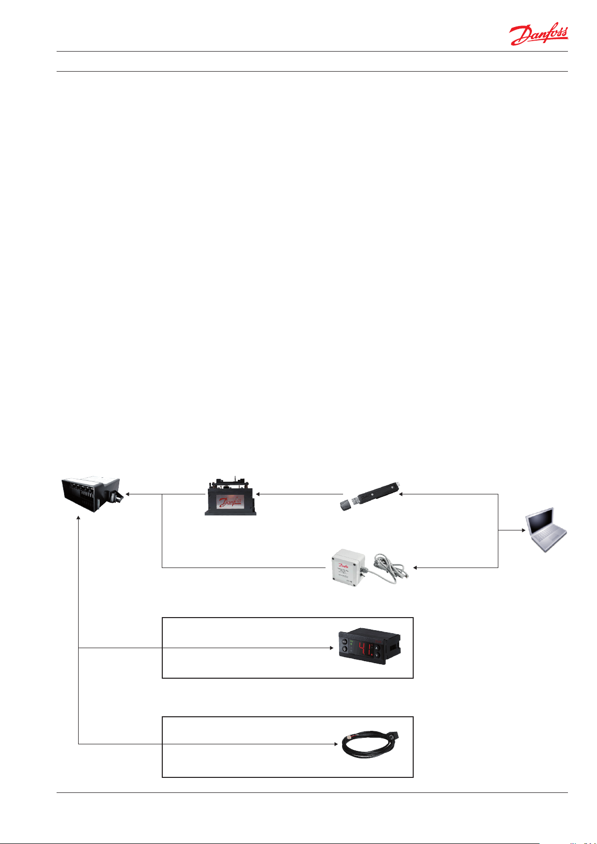
Overview of the ERC 113 application setups:
stand-alone, remote display and remote spindle.
The ERC 113 stand-alone controller can be equipped with a variety of accessories, including remote display, remote spindle and multiple
sensors.
Overview of the system The ERC 113 stand-alone controller is easily
programmed using the Danfoss docking station
or a gateway.
Connect your PC to the USB gateway and the USB
gateway to the ERC 113 and configure all
parameters online. Use the gateway for various
monitoring purposes in your laboratory,
e.g. to verify your parameter setting.
Docking station:
download the desired parameters from a
computer to an EKA 183 with USB interface.
Then put the EKA 183 into the Danfoss docking
station and place the ERC 113 controller on the
docking station to download the parameters
from the EKA 183.
Gateway:
download the desired parameters from a
computer to the gateway.
Then plug in the gateway into the ERC 113
controller to program it.
ERC 113 can also communicate with remote
displays (e.g. RDI 107) over 1 wire communication
interface or it can be controlled by the remote
spindle RSP 01 through an edge connector.
ERC 113
optional
accessory
optional
accessory
docking station EKA183
communication
remote display
remote spindle
one-wire
one-wire
communication
edge
connector
gateway
RDI 107
RSP 01
USB
USB
PC
Produced by Danfoss A/S (ADAP-KOOL®) | 2016-07
DKRCC.ES.RL0.F5.02
3
Page 4
User manual ERC 113 refrigeration controller
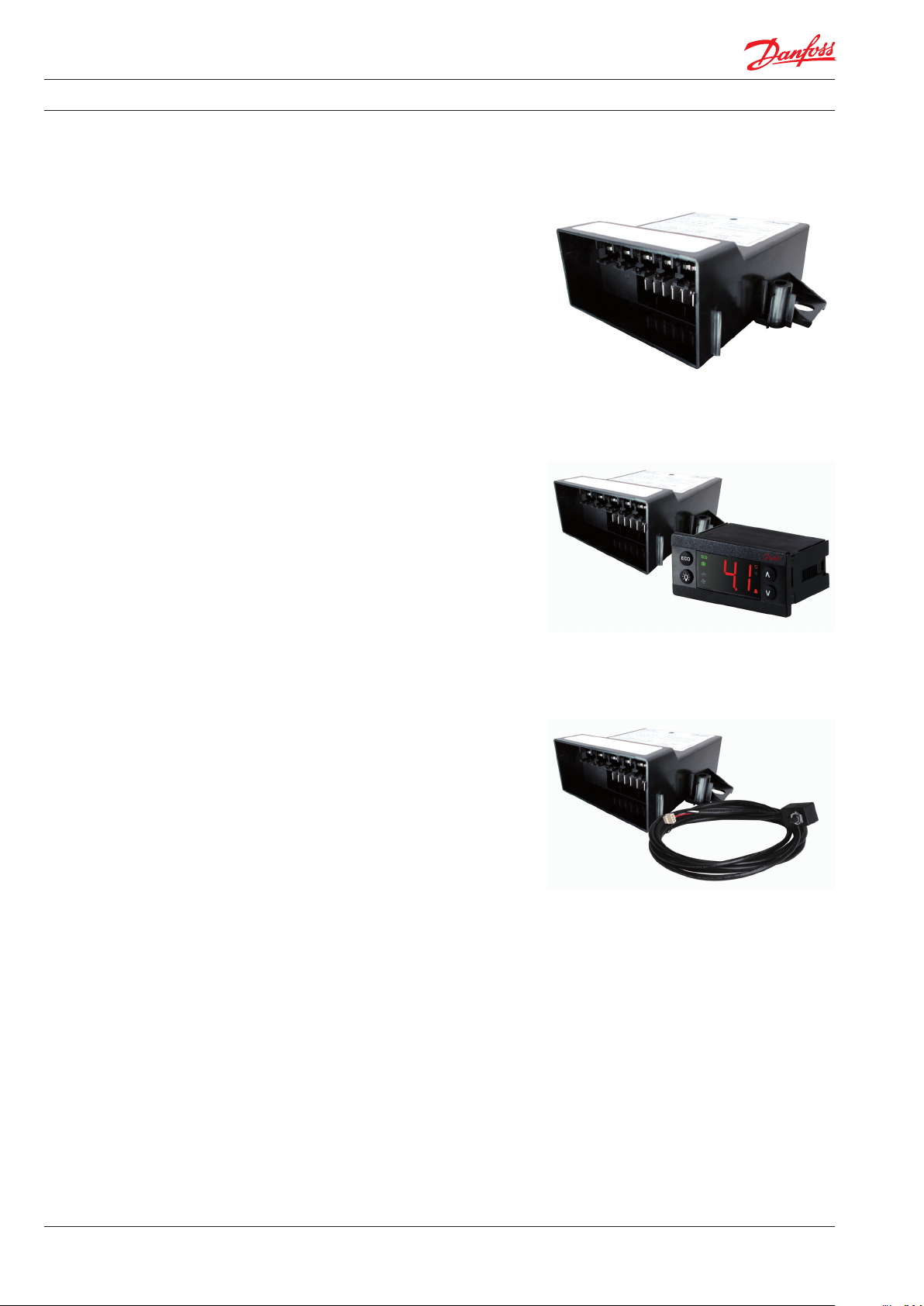
Application setup
1) ERC 113 stand-alone
2) ERC 113 + remote display
The ERC 113 is an IP-rated stand-alone controller
for use in applications such as beer coolers and
counter-top bottle coolers (e.g. in petrol stations).
With input from multiple sensors, the
cost-efficient controller delivers energy-saving
routines as well as providing control of
compressor, light, fan and defrost functions.
Using the Danfoss docking station, programming
of pre-prepared parameter settings can be
achieved in just ten seconds
The ERC 113 + remote display (RDI 107) is ideal
for commercial freezers and fridges as well as
glass door merchandisers.
ERC remote displays allow for temperature
indication and user interaction alike in an
embedded controller but with the flexibility of a
split system (up to 3 meters cable length)
3) ERC 113 + remote spindle
The ERC 113 + remote spindle provides a
controller solution with the look and feel of
mechanical thermostats, ideally suiting
refurbishment solutions and cost optimized
commercial refrigeration equipment.
The remote spindle wiring is available up to 3
meters length. The spindle offers a stop function
(appliance ON/OFF switch)
4
DKRCC.ES.RL0.F5.02 Produced by Danfoss A/S (ADAP-KOOL®) | 2016-07
Page 5
User manual ERC 113 refrigeration controller
Configuration of inputs and outputs
ERC 113 inputs and outputs
Possible input and output
connections
The ERC 113 inputs and outputs are configurable
by the customer. Before getting started it is a
good idea to check if all inputs are configured
correctly and match the sensors attached.
Input and output configuration settings are part
of the assignment menu "ASi".
NOTE: Coded sensors will impact on the number of
possible configurations
For instance:
Danfoss supplies only 2-pole defrost sensors, so
input "S3" will most likely be used as a
defrost/evaporator temperature sensor input.
Please contact your local Danfoss representative
for information about default settings.
NOTE: remote display is always connected to the
digital input "Di" an d configured as "buS", whilst
remote spindle is always connected to "S3" and
configured as "rSp"
Inputs/outputs Stand-alone With remote display
RDI 107
Sensor 1 X X X
Sensor 2 X X X
Sensor 3 X X
Sensor 4 X X X
Sensor 5 X
Sensor 7 X
Relay 2 X X X
Relay 3 X X X
Relay 4 X X X
Relay 5 X
DI (not com) X X
The table shows the possible input and output connections for the three application setups:
ERC 113 stand-alone, ERC 113 + remote display and ERC 113 + remote spindle.
With remote spindle
RSP 01
Produced by Danfoss A/S (ADAP-KOOL®) | 2016-07
DKRCC.ES.RL0.F5.02
5
Page 6
User manual ERC 113 refrigeration controller
Operation
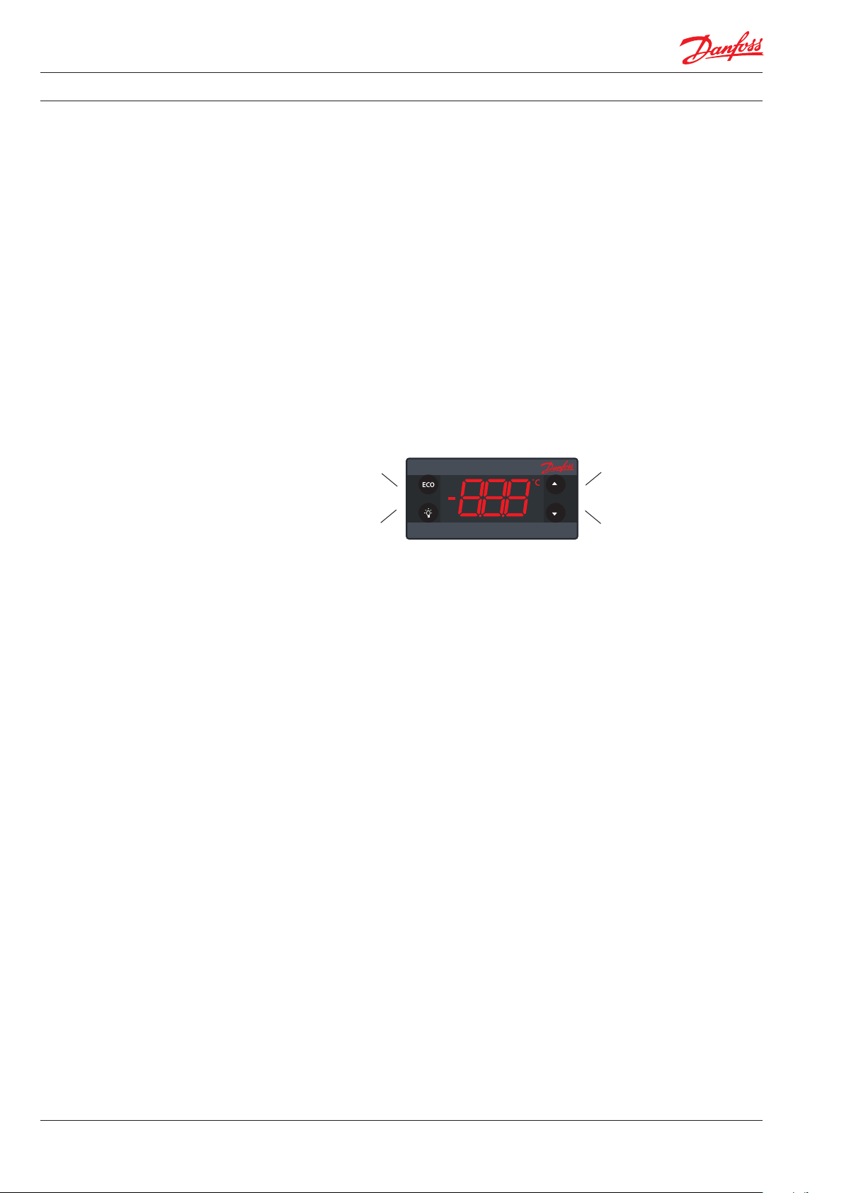
Software tool/Gateway
Docking station
Manual operation with
buttons (Direct Access)
Examples
The controller can be controlled in three ways:
Using "Software tool", the Danfoss Docking
Station or manually by means of the buttons on
the front panel.
"Software tool" is licenced Danfoss software
offering easy parameter set up via a USB gateway.
This software is supplied separately;
for technical literature and further information,
please contact your local Danfoss representative.
Docking station is supplied separately.
For further information, please contact your local
Danfoss representative.
1 Press: variable direct
function, e.g. “ECO”/”Night mode”
Sub function: back
1 Press: variable direct
function, e.g. light
Sub function: “OK”
Changing the desiredtemperature set point:
1. The display shows the current temperature.
2. Press "up/down" to access set point.
3. Press "up/down" to adjust set point.
After 30 seconds, the display automatically
reverts to showing the current temperature
Turning ON/OFF the ECO function:
1. Press "ECO".
The green "ECO" symbol is lit when in "ECO"
mode.
Turn ON/Off the light:
1. Press the "Light" button.
Acknowledging alarms:
1. Display Flashing the alarm message.
2. Press any button to acknowlege.
1 Press: temperature set point
Sub function: “up”
1 Press: temperature set point
Sub function: “down”
Changing a parameter
Some parameters may be hidden to you.
When scrolling through menus, the parameters
available will have been pre-determined using
"Software tool".
Your access level will determine which
parameters you can view and edit:
1. Press "up/down" and hold 5 seconds to access
the menu.
2. First parameter group is shown "tHE".
3. Press "up/down" to find the desired group.
4. Press "OK".
5. First parameter is shown.
6. Press "up/down" to find the desired
parameter.
7. Press "OK".
8. Press "up/down" to find the desired setting.
9. Press "OK".
Password protection:
1. Press "up/down" and hold 5 seconds to access
the menu.
2. The display shows "PAS".
3. Press "OK".
4. Press "Up/Down" to the code.
5. Press "OK".
Password protection on three levels:
1. Level 1: "shop" (daily use by shop personnel).
2. Level 2: "ser" (service technician).
3. Level 3: "OEM" (OEM programming).
6
DKRCC.ES.RL0.F5.02 Produced by Danfoss A/S (ADAP-KOOL®) | 2016-07
After 30 seconds, the display automatically
reverts to showing the current temperature.
Or press 2 x "Back".
NOTE:
Incorrect parameter settings can lead
to inadequate cooling, excessive energy
consumption, unnecessary alarms and in the case
of temperature-sensitive food storage, breaches in
food hygiene principles and regulations.
Only a trained operator should make changes to
parameters.
Page 7
User manual ERC 113 refrigeration controller
Menu/functions
ERC menu code Description
"tHE Thermostat settings
"SEt"
Min. -100.0°C
Max. 200.0°C
Default 2.0°C
"SPr"
Min. 0.0
Max. 1.0
Default 0.5
"diF"
Min. 0.0 K
Max. 20.0 K
Default 2.0 K
"HSE"
Min. -100.0°C
Max. 200.0°C
Default 50.0°C
"LSE"
Min. -100.0°C
Max. 200°C
Default -35.0°C
"iCi"
Min. no
Max. yes
Default no
"SSA"
Min. 0
Max. 80
Default 30
FAn Fan settings
"FCt"
Default FAo
"Fod"
Min. 0 s
Max. 240 s
Default 0 s
"FSd"
Min. 0 s
Max. 240 s
Default 0 s
"FoC"
Min. 0 s
Max. 960 s
Default 0 s
"FSC"
Min. 0 s
Max. 960 s
Default 0 s
"FSt"
Min. 0 s
Max. 960 s
Default 10 s
Set point
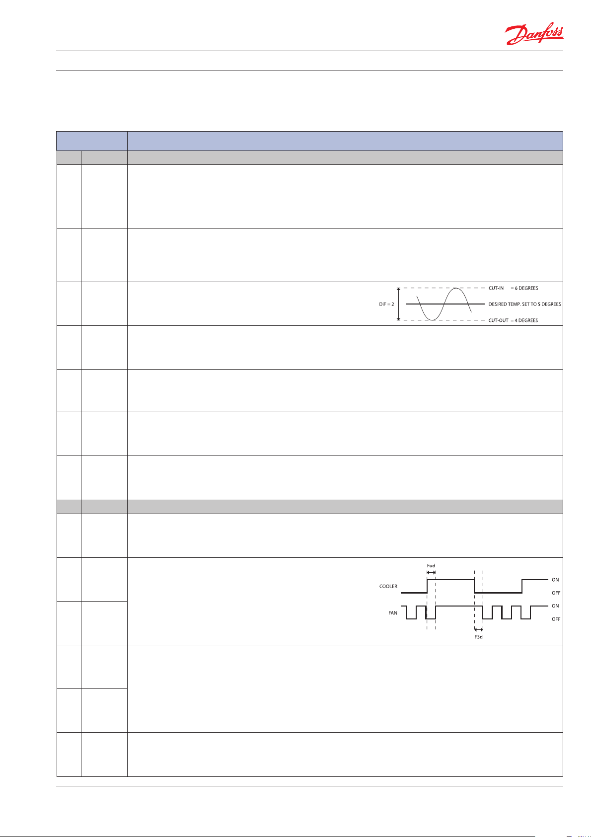
This parameter defines the desired temperature (set point).
In standard operation the set point is changed by simply pressing the
"temperature up/down" buttons on ERC 112; for laboratory and
assembly line you may opt for software controlled set point adjustment
(speed improvement)
Current set point adjustment value diF * SPr
The default value is set to 0.5 and the parameter is hidden by default.
"Spr" defines the position of the set point in relation to cut-in and cut-out.
"Spr=0,5" sets the set point mid between cut-in and cut-out.
"Spr=0" sets the set point at the cutout. "Spr=1" sets the set point at cut-in.
Thermostat differential
This defines the difference between the cut-out and the cut-in.
The desired temperature is determined by "SPr" and "diF".
Upper limit of thermostat set point
Define the temperature range limit of the controller.
Once set, the desired temperatue (set point) can not go above "HSE" or
below "LSE".
Lower limit of thermostat set point
Define the temperature range limit of the controller.
Once set, the desired temperatue (set point) can not go below "LSE".
Initial cut in
Comp relay action when Tair is between cut-in and cut-out at power-up:
"yES": cut in the compressor.
"no": cut out the compressor.
Spindle stop angle
Set to zero to disable stop function.
Set to 30 to enable stop function.
Fan control method
"FAo": fan always on
"SEt": fan follow compressor by manually settings
"Aut": automatical fan control
Fan ON Delay/Fod
Fod defines the fan delay (in seconds) after a compressor cut-in.
Fan Stop Delay/FSd
"FSd" defines the fan delay after a compressor cut-out.
If both "Fod" and "FSd" are set to zero then the fan runs whenever the
compressor runs.
Fan ON Cycle/FoC
Fan Stop Cycle/FSC
When the compressor is OFF, and "FoC" or "FSC" are not zero, the fan
runs in cycles according to "FoC" and "FSC".
Example: "FoC=120" [sec] and "FSC=120" [sec] means that the fan runs
for half the time when the compressor is OFF. When the compressor is
on, the fan is always ON (according to "FAo" and "Fod").
Fan Minimum Stop time
Minimum stop time for fan protection.
Produced by Danfoss A/S (ADAP-KOOL®) | 2016-07
DKRCC.ES.RL0.F5.02
7
Page 8
User manual ERC 113 refrigeration controller
"FdC"
Min. -10.0 K
Max. 10.0 K
Default 0.0 K
"Fdt"
Min. 0 s
Max. 999 s
Default 0 s
Fan Δt cut in
Delta T for fan to cut in which the temperature offset comparing with
thermostat cut in temperature.
Fan stop time on door open
The delay with wich the fan will be stopped after the door has been opened.
"0": fan stop immediately when door open.
"1-998": delay for fan stop after door open.
"999": fan keep running all the time during door open.
Lig Light settings
"CLC "
Min. on
Max. dor
Default on
Cabinet Light Source Control
This parameter can be set to one of these alternatives to control the light
in the cabinet:
"on": always ON.
"oFF": always OFF.
"dor": door sensor only.
"Lod"
Min. 0 s
Max. 300 s
Default 0 s
Light OFF delay
Number of seconds the light will stay ON after the door has been closed.
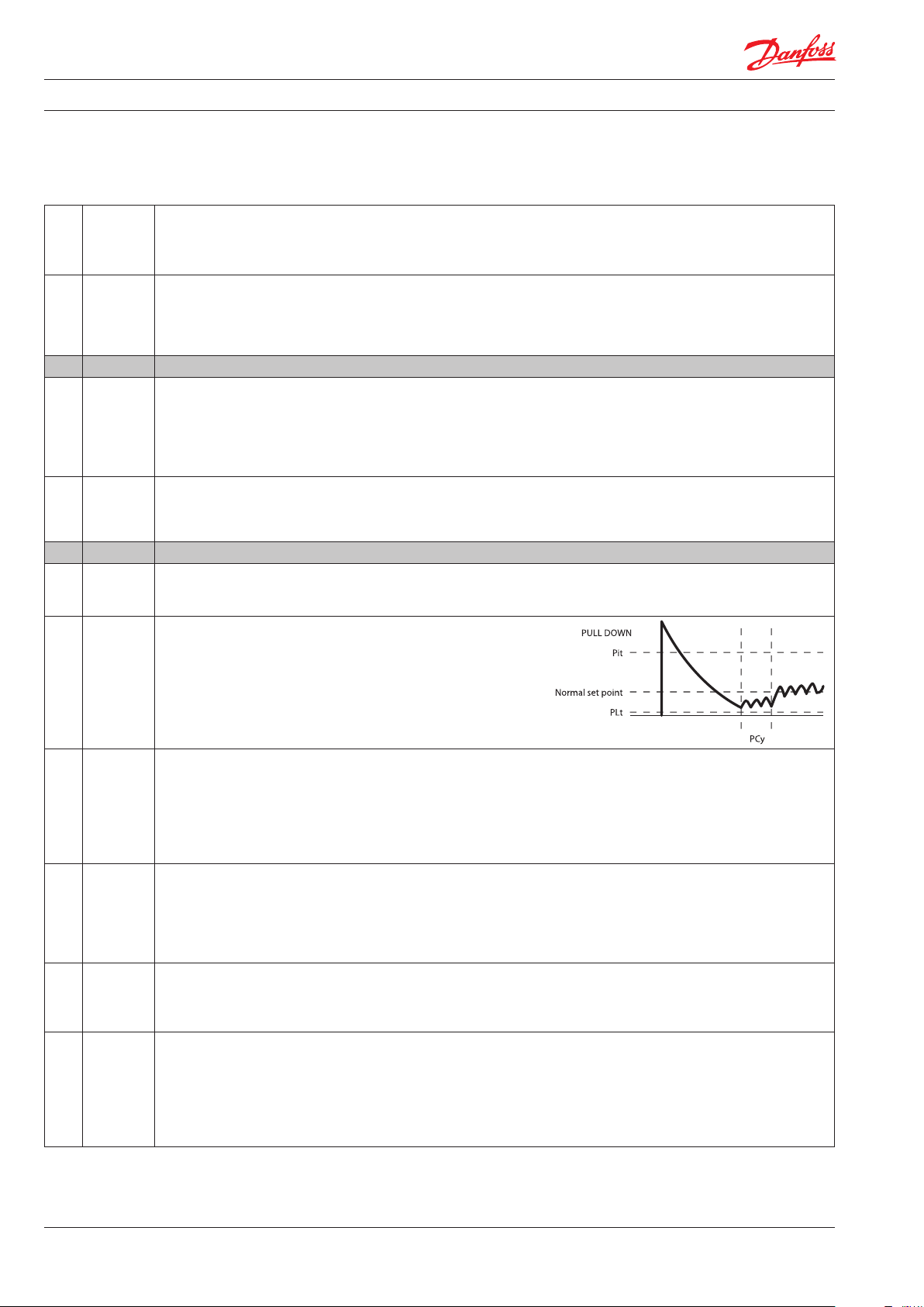
Pud Pull Down settings
Pull down (sometimes known as Super Cool) is a procedure for improving
cooling performance, accelerating the time used to reach the desired
temperature. Pull down settings overrule all other settings.
"Pit"
Min. -40.0°C
Max. 50.0°C
Default 50.0°C
Pull Down Initiate Temperature
This parameter indicates the temperature which causes a pull
down to start. If the temperature measured inside the cabinet
exceeds this value for longer than one hour, then pull down will
start. The compressor will have already cut-in, so the only effect
is to stop defrost cycles until the desired temperature is reached.
The period of one hour is fixed and cannot be altered.
"PCy"
Min. 0 min
Max. 360 min
Default 30 min
"Pdi"
Min. 0 hour
Max. 48 hour
Default 15 hour
"Pdd"
Min. 0 hour
Max. 48 hour
Default 24 hour
"PLt"
Min. -55.0°C
Max. 55.0°C
Default 0.0°C
Pull Down Cycling
This is the duration in minutes of the compressor cycling at the reduced
set point temperature. Once the desired pull down limit temperature
"PLt" has been reached during pull down, the compressor will continue to
cycle ON/OFF for the duration of "PCy". At the end of the period defined by
"PCy", the set point temperature will return to normal and pull down will
cease.
Pull Down Defrost Interval
Even though most applications do not need Defrost during pull down, an
extended defrost during pull down can be applied. This is the time
between defrost cycles during pull down. It is measured in hours and can
be up to 48 hours. During pull down, this setting overrides the defrost
interval and defrost time settings (see the defrost section).
Pull Down Duration
You can choose to limit the maximum pull down time. Once this time
value (max. 48 hours) is reached, pull down will stop regardless of
whether the desired pull-down temperature has been reached.
Pull Down Limit Temperature
This parameter sets the minimum allowed temperature during pull-down.
In order to protect valuable contents you must always specify the absolute
minimum temperature allowed in your application.
For glass door merchandisers 0°C/32°F protects bottles from freezing;
for commercial fridges you may opt for a slightly higher temperature
(e.g. 2°C)
8
DKRCC.ES.RL0.F5.02 Produced by Danfoss A/S (ADAP-KOOL®) | 2016-07
Page 9
User manual ERC 113 refrigeration controller
"Prt"
Min. 0.0 K
Max. 10.0 K
Default 0.1 K
Pull Down Reduction Temperature Δt
The controller calculates a lower set point during pull down mode to
increase the cooling capacity of your appliance. For each hour the
cabinet temperature is above the pull down initiate temperature,
the set point is reduced with the value of "Prt".
dEF Defrost settings
"dFt"
Default no
Defrost Type
"no": defrost function is disabled.
"EL": electrical or time defrost.
"Hgd": hot gas defrost (contact Danfoss for details).
"nat": OFF-cycle defrost (natural defrost).
"Add"
Min. no
Max. yes
Default no
"dtt"
Min. 0.0°C
Max. 25.0°C
Default 6.0°C
"drt"
Min. 0.0°C
Max. 200.0°C
Default 5.0°C
Adaptive defrost
"no": defrost controlled by time.
"yES": automatic defrost control activated.
Terminate Temperature
This parameter defines at what temperature the defrost cycle will stop.
The temperature is given by the evaporator sensor or by the cabinet
temperature sensor if no evaporator sensor is used.
Defrost reset temperature
The defrost counter is saved and restored at power-up, but if the
temperature sensor, used for defrost, is higher than this value at
power-up, it is assumed that the evaporator is free of ice and the
defrost counter will be cleared.
"dii"
Min. 1 hour
Max. 96 hour
Default 6 hour
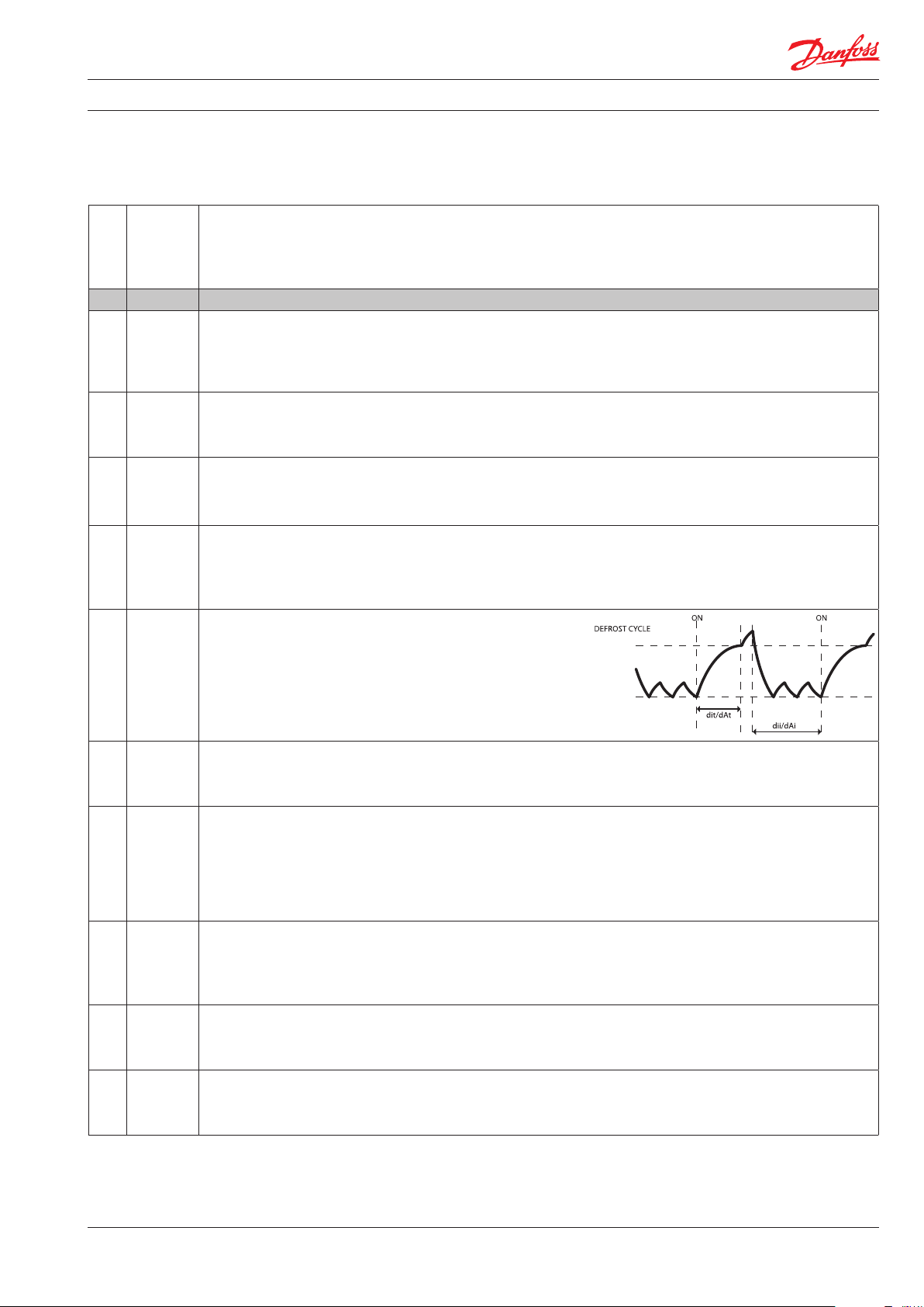
Defrost minimum Interval/dii
Defines the minimum time period between the start of two defrost cycles.
Once the minimum interval has expired, the defrost cycle will start at
the following cut-out or once the maximum interval "dAi" has been
reached.
"dAi"
Min. 1 hour
Max. 96 hour
Default 7 hour
"dit"
Min. 0 min
Max. 240 min
Default 5 min
"dAt"
Min. 0 min
Max. 480 min
Default 30 min
"dot"
Min. 0 min
Max. 60 min
Default 0 min
"Fdd"
Min. 0 s
Max. 600 s
Default 0 s
Maximum Interval
Defines the maximum time period between the start of two defrost cycles.
Minimum Time
Defines the minimum duration of a defrost cycle. During this period, the
controller will not check the temperature. Once the minimum time has
expired, the temperature will be checked and if the terminate temperature
"dtt" has been reached, the defrost cycle will end. If dtt has not been
reached, defrost will continue until either dtt is reached or the
maximum time "dAt" reached, whichever occurs first.
Maximum Time
Defines the maximum duration of a defrost cycle.
The controller will not allow a maximum time to be entered which is
less than the minimum time, or a minimum time which is more than the
maximum time.
Drip OFF Time
This parameter can be set to between 0 and 60 minutes and defines how long the delay is between the heater being switched
OFF and the compressor starting again.
Fan Delay after Defrost
Defines how long the delay is between the start of the compressor after
defrost and the fan starting again.
Produced by Danfoss A/S (ADAP-KOOL®) | 2016-07
DKRCC.ES.RL0.F5.02
9
Page 10
User manual ERC 113 refrigeration controller
"Ftd"
Min. -25.0°C
Max. 25.0°C
Default 25.0°C
"dFA "
Min. no
Max. yes
Default no
"dCt"
Min. no
Max. yes
Default no
"doC"
Min. 0 hour
Max. 24 hour
Default 0 hour
"dEt"
Min. -50.0°C
Max. 0.0°C
Default -50.0°C
"ddt"
Min. 0.0 K
Max. 30.0 K
Default 5.0 K
Fan Start Temperature
This only applies if an evaporator temperature sensor is fitted.
This parameter determines at what evaporator temperature the fan will
start after a defrost cycle is complete.
If the time set in "Fdd" occurs before the temperature set in "Ftd", the fan
will start in line with "Fdd". If the temperature set in "Ftd" occurs first,
then the fan will start in line with "Ftd". It is therefore a case of whichever
parameter’s setting is reached first which determines when the fan starts.
Defrost Fan On
Set to "yES", the fan will constantly run during defrost cycles.
Set to "no", the fan will not run during defrost cycles.
Defrost ON Compressor Time
If this parameter is set to "yES", then defrost time is considered only when compressor is ON, so that defrost cycles are based on
the total time the compressor has been running. If this parameter is set to no, then defrost cycles are related to elapsed time,
regardless of how long and how often the compressor has been on.
Defrost by Comp. running time
Continuous compressor running can cause defrost.
"0" = deactived
Defrost start evaporator temp
Defrost start trigger for adaptive defrost.
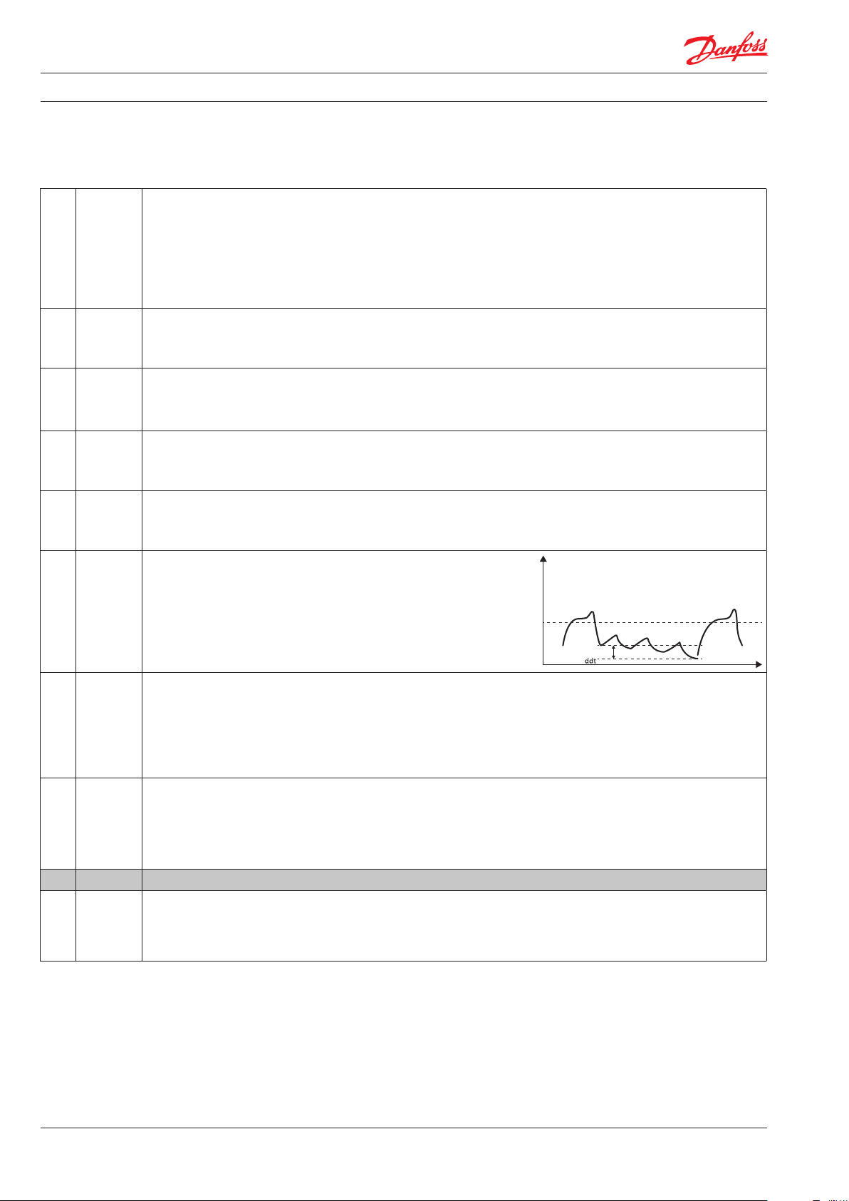
Defrost Δt
Defrost Δt compare with evaporator temperature of first cut out after
defrost to trigger defrost start.
The defrost start if evaporator temperature has decreased more the "ddt"
"idi"
Min. 0 hour
Max. 96 hour
Default 3 hour
Initial Defrost Interval
The initial defrost interval determines the time for first defrost after
power-up. The initial defrost is mainly intended for factory testing of the
defrost functionality and can be set to expire after a number compressor
cycles according to the setting of parameter idd. During normal operation,
the defrost counter will be saved in memory and restored after power loss,
making the initial defrost unnecessary.
"idd"
Min. 0
Max. 999
Default 100
Initial Defrost Duration
The initial defrost duration is the number of compressor cycles before
the initial defrost is deactivated.
"0": "idi" No initial defrost.
"1-998": number of compressor cycles before deactivation.
"999": initial defrost always active.
CoP Compressor settings
"uPt"
Voltage protection
"no": no voltage protection.
Min. no
Max. yes
Default no
"yES": voltage protection activated based on voltage related settings.
10
DKRCC.ES.RL0.F5.02 Produced by Danfoss A/S (ADAP-KOOL®) | 2016-07
Page 11

User manual ERC 113 refrigeration controller
"uLi"
Min. 0 V a.c.
Max. 270 V a.c.
Default 0 V
"uLo"
Min. 0 V a.c.
Max. 270 V a.c.
Default 0 V
"uHi"
Min. 0 V a.c.
Max. 270 V a.c.
Default 270 V
"EHd"
Default no
"Ert"
Min. 0 min
Max. 60 min
Default 0 min
"ESt"
Min. 0 min
Max. 60 min
Default 1 min
"CSt"
Min. 0 min
Max. 30 min
Default 2 min
"Crt"
Min. 0 min
Max. 30 min
Default 0 min
"Cot"
Min. 0 min
Max. 480 min
Default 0 min
"Cdd"
Min. 0 min
Max. 15 min
Default 0 min
"Srt"
Min. 0 min
Max. 60 min
Default 0 min
Minimum cut-in voltage/uLi. Minimum cut-out voltage/uLo.
Maximum voltage/uHi
These three parameters provide voltage protection to the compressor.
Start by setting "uHi", followed by "uLo" and "uLi".
"uLi": when the compressor is due to start, the voltage of the power
supply will be checked and the compressor will only be allowed to
start if it is at least the value given in this parameter.
"uLo": when the compressor is running, it will be switched
OFF if the voltage goes below that given in this
parameter.
"uHi": when the compressor is running, it will be switched
OFF if the voltage exceeds that given in this parameter.
If the compressor is already stopped, it will remain
switched OFF.
Sensor Error Type
"no": no sensor error handling.
"SEt": in case of control sensor error, follow error run/stop time.
"Aut": automatical sensor error handling.
Error Run Time
The parameter only become active in the unlikely event of a broken
temperature sensor. It is used to run the application in safety mode.
At the same time the sensor error will be shown in the display.
"Ert" define the duration the compressor will run.
Example: "Ert=4" [min] and "ESt=16" [min] will provide an average cooling
system activity of 20%. Ert and "ESt" values are based on OEM experience
and are by default inactive.
Error Stop Time
The parameter only become active in the unlikely event of a broken
temperature sensor. It is used to run the application in safety mode.
At the same time the sensor error will be shown in the display.
"ESt" define the duration the compressor will be "idle".
Minimum Stop Time
It determines the minimum number of minutes the compressor must
remain idle before a Temperature cut-in can take effect. For example,
if the temperature sensor indicates that the cut-in temperature has been
reached, but the number of minutes set in this parameter have not elapsed
since the compressor last stopped, then the compressor will stay OFF.
It will only start once the duration given by "CSt" has been reached
provided the temperature is still high enough. "CSt" thus overrides the cut-in.
Minimum Run Time
It determines the minimum number of minutes the compressor must run
before a Temperature cut-out can take effect. For example, if the
temperature sensor indicated that the cut-out temperature has been
reached, but the number of minutes set in this parameter have not
elapsed since the compressor last started, then the compressor will
continue. It will only stop once the duration given by "Crt" has been
reached – provided the temperature is still low enough.
"Crt" thus overrides the cut-out.
Maximum OFF Time
This is the maximum time in minutes the compressor is allowed to
"idle" – up to 480 minutes. Cot is set to zero by default (inactive).
If the controller is used on a draft beer (ice bank) application, this
parameter can be used to control the ice thickness.
Compressor Door Open Delay/Cdd
This parameter sets the delay in minutes before the compressor stops
when the door is opened. If set to zero, the function is disabled.
System resume after door open
Fan and Compressor resume after cut out by door open.
Produced by Danfoss A/S (ADAP-KOOL®) | 2016-07
DKRCC.ES.RL0.F5.02
11
Page 12

User manual ERC 113 refrigeration controller
"Pod"
Min. 0 s
Max. 300 s
Default 300 s
"Pot"
Min. -100.0°C
Max. 200.0°C
Default -100.0°C
Power ON Delay
This is the delay in seconds between power-on and the compressor being
activated.
Depends on the power ON temperature setting as explained below.
Power ON Temperature
This parameter is used to accelerate the first application test on the
OEM assembly line; if the cabinet temperature is higher than this
parameter the power ON Delay is overruled and the outputs are activated
without delay.
Con Condenser Protection settings
NOTE: A condensor temperature sensor is required to use these parameters.
Condenser protection is generally used in dusty environments where
the condenser may accumulate a layer of dust or dirt and therefore be
at risk of overheating.
"CAL"
Min. 0°C
Max. 200°C
Default 80°C
"CbL"
Min. 0°C
Max. 200°C
Default 85°C
"CoL"
Min. 0°C
Max. 200°C
Default 60°C
"CLL"
Min. -100°C
Max. 20°C
Default -5°C
Condenser Alarm Limit/CAL
This parameter sets the temperature for the condenser at which an alarm
will be generated.
Condenser Block Limit/CbL
This parameter sets the temperature which if reached will cause the
compressor to switch OFF.
Condenser OK Limit/CoL
This parameter sets the temperature at which the compressor is
allowed to start again after the temperature set in "CbL" above has been
exceeded and the compressor stopped.
Condenser Low Limit/CLL
This parameter sets the lowest (condenser) temperature at which the
compressor is allowed to start.
diS Display settings
NOTE: some display parameters can be set in such as way that they
may be illegal in some jurisdictions. Please check local legislation.
"diC"
Min. no
Max. yes
Default no
"din"
Min. 2
Max. 10
Default 10
Display intensity auto control
"no": display intensity use fixed value.
Display Intensity
The controller can have its display intensity (brightness) set in one of
two ways:
A) With a Danfoss ambient light sensor attached, the brightness of the
display is adjusted automatically according to the ambient light level
(see the assignments section).
B) When no ambient light sensor is attached, the display intensity can
be set to a fixed intensity.
Both options are on a scale of 1 to 10, where 10 is the brightest.
"CFu"
Min. °C
Max. °F
Default °C
"trS"
Default SCo
Display Unit
This parameter sets the display to Fahrenheit or Celsius. Switching from
one to the other will cause all temperature settings to be automatically
updated accordingly.
Temp sensor to display
"SCo": temperature control.
"EuA": evaporator temperture.
"Con": condenser temperature (condenser cleaning).
"AuS": only for showing on display.
12
DKRCC.ES.RL0.F5.02 Produced by Danfoss A/S (ADAP-KOOL®) | 2016-07
Page 13

User manual ERC 113 refrigeration controller
"rES"
Min. 0.1
Max. 1
Default 0.1
"rLt"
Min. no
Max. yes
Default no
"ddL"
Min. 0 s
Max. 10 min
Default 0 min
"doF"
Min. -10.0 K
Max. 10.0 K
Default 0.0 K
"dLt"
Min. 0 min
Max. 60 min
Default 15 min
"SEC"
Min. no
Max. yes
Default no
"SSC"
Min. no
Max. yes
Default no
"SHo"
Min. no
Max. yes
Default no
"SdF"
Min. no
Max. yes
Default yes
Display Resolution
This parameter can be set to 0.1, 0.5 or 1 and affects the way the
temperature is displayed. With the parameter set to 1, the display will
only ever show temperatures rounded to the nearest whole degree.
At 0.5, it will round the temperature to the nearest half degree for display.
For example, 3.3 degrees will be shown in the display as 3.5 degrees
and 3.9 as 4.0. With the parameter set to 0.1, no rounding occurs.
This parameter does not affect the temperature itself, merely the display.
Display Range Limit
In some point of sales applications you may want to show the desired
instead of the real temperature. This parameter sets whether the
displayed temperature is the actual temperature or whether it is restricted
to the cut-in / cut-out limits. Set to "nO" means that the actual temperature
will de displayed. The parameter is set to "nO" by default.
Display Delay
In order to provide a realistic temperature appearance for an application,
a display delay can be set.
The parameter sets the time constant τ (tau) of the moving average filter
for the display.
Physically, one time constant represents the time it takes the system’s
step-response to reach 66% of its final value and five time-constants
the time it takes to reach 99% of its final value.
Display Offset
This parameter is a relative value and allows the temperature displayed
to be different to the temperature measured.
For instance, at a measured temperature of 7°C and "doF" set to -2K, the
displayed temperature will be 5°C instead.
Lock Time After Defrost
In order not to show a rising temperature during defrosting, the displayed
temperature is locked at the temperature shown at the start of the defrost
cycle for the number of minutes set in this parameter.
"0": no lock.
Show Economy State
If set to "yES", this parameter causes the display to show ECO when the
system is in ECO mode.
If set to "nO", the temperature continues to be displayed.
Show Pull down state
If set to "yES", this parameter causes the display to show SC when the
system is in pull down mode.
If set to "nO", the temperature continues to be displayed.
Show Holiday
"no": display will show temperature or ECO mode during holiday mode.
"yES": display will show "HoL" during holiday mode.
Show Defrost
If set to "yES", this parameter causes the display to show DEF when the
system is in defrost mode. If set to "nO", the temperature continues to
be displayed.
"SCS"
Min. no
Max. yes
Default yes
"SFS"
Min. no
Max. yes
Default yes
Produced by Danfoss A/S (ADAP-KOOL®) | 2016-07
Show compressor symbol
"no": compressor symbol will not show on display.
"yES": show compressor symbol on display.
Show Fan symbol
"no": san symbol will not show on display.
"yES": show fan symbol on display.
DKRCC.ES.RL0.F5.02
13
Page 14

User manual ERC 113 refrigeration controller
"SdS"
Min. no
Max. yes
Default yes
"SES"
Min. no
Max. yes
Default yes
Show Defrost symbol
"no": defrost symbol will not show on display.
"yES": show defrost symbol on display.
Show ECO symbol
"no": ECO symbol will not show on display.
"yES": show ECO symbol on display.
ALA Alarm settings
"HAt"
Min. -100.0°C
Max. 200°C
Default 15.0°C
"LAt"
Min. -100.0°C
Max. 200°C
Default -50.0°C
High Temp Alarm
Absolute value.
By setting "HAt" to the maximum alarms will be deactivated.
Low Temp Alarm
Absolute value.
By setting "LAt" to the minimum value, alarms will be deactivated.
In most situations, the low alarm delay will be set to 0 to warn about
too low a temperature immediately.
"Htd"
Min. 0 min
Max. 240 min
Default 30 min
"Ltd"
Min. 0 min
Max. 240 min
Default 0 min
"Pdd"
Min. 0 min
Max. 960 min
Default 240 min
Alarm delay on high temperature alarm
The number of minutes to wait before sounding an alarm once the
high temperature alarm temperature is reached.
Alarm delay on low temperature alarm
The number of minutes to wait before sounding an alarm once the
low temperature alarm temperature is reached.
Pull down delay
Normally, it is not necessary or desirable to sound an alarm during a pull
down (the initial phase of reaching the desired temperature). This
parameter prevents the high temperature alarm "HAt" sounding during pull down
and after a defrost for the number of minutes set for the parameter.
NOTE: it does not apply to the low temperature alarm "LAt".
"dod"
Min. 0 min
Max. 60 min
Default 2 min
Door Open delay
It is possible to indicate to customers that a door has accidentally been
left open. This parameter sets the delay in minutes before the alarm sounds.
This is useful in environments where customers/users may hold the door
open while making their selection. If the door is closed again before
the set number of minutes is reached, the alarm does not sound.
NOTE: a door sensor is required if this parameter is to be activated.
"uAL"
Min. no
Max. yes
Default no
"LEA"
Min. 0 hour
Max. 96 hour
Default 0 hour
"Abd"
Min. 0 min
Max. 999 min
Default 0 min
Voltage alarm
"no": no voltage alarm.
"yES": voltage alarm activated.
Leakage alarm
Leakage detection for compressor protection.
"0": disable
Alarm Buzzer Duration
The alarm sounds for 10 seconds, followed by silence for 50 seconds.
One alarm sequence therefore lasts 60 seconds. These values cannot be
changed. This parameter determines how long in minutes an audible
alarm will continue while there is still a reason to have an alarm.
If set to 999, the alarm will continue to sound until the reason for the
alarm is cleared – for example the temperature has dropped enough or
the door closed. In some cases, it may be necessary for a user or technician
to take action in order to clear the alarm. If set to 0, the alarm will never
sound.
14
DKRCC.ES.RL0.F5.02 Produced by Danfoss A/S (ADAP-KOOL®) | 2016-07
Page 15

User manual ERC 113 refrigeration controller
"ACA"
Min. no
Max. yes
Default yes
Auto Clear of Alarm/Error/ACA
If this parameter is set to "nO":
The alarm status will not disappear automatically even if the condition
which caused the alarm is no longer valid or present.
If set to "yES":
As soon as the condition which caused the alarm is no longer valid or
present, the alarm status will automatically change back to inactive.
There will be no trace of the alarm having occurred.
In general, glass door merchandise applications will be set to "yES" and
commercial fridges and freezers set to "nO".
For example, if the temperature goes too high for a period there may
be food safety considerations in a freezer containing food but not in a
fridge with cold drinks.
AHC Automatic Heater settings
Automatic Heater Control applies reverse cooling mode
(heating) to your refrigeration appliance.
This feature requires:
A) that your appliance is exposed to ambient temperatures
below the desired temperature in your cabinet
(e.g. very cold climates and outdoor use).
B) a special heater (for example a large defrost heater) built in
to your appliance.
"AuH"
Min. no
Max. yes
Default no
"End"
Min. 0 min
Max. 360 min
Default 60 min
Automatic Heater Mode Enable
This setting is normally set to "no".
When set to "yES", parameters "End" and "Hdi" apply.
Energy Mode Delay
This is the delay in minutes between the heater and the compressor
operation. The heater is not allowed to start until this number of minutes
has expired after the compressor has cut out and vice versa.
"AHS"
Min. -100.0°C
Max. 200.0°C
Default 2.0°C
"AHd"
Min. 0.0 K
Max. 20.0 K
Default 2.0 K
Auto Heat set point
Set point of auto heating.
Auto heat differential
Thermostat differential for auto heatting.
ECS ECO strategy
NOTE: some of these parameters require the installation of the
Danfoss Ambient Light Sensor. The Danfoss USB Gateway in combination
with "Software tool" allows for real time measurement of the current
light intensity. Danfoss recommends testing and adjusting "SLd" and "SLn"
values according to customers’ specific needs.
"ECo"
Min. no
Max. yes
Default Yes
"EdA"
Min. 1
Max. 10
Default 1
"EPA"
Min. 1
Max. 10
Default 1
ECO ON/OFF
ECO active or not. If no all other settings are not active.
Door Actions
Times of door action to trigger exiting ECO
(Can only be accessed by Danfoss)
Pir Actions
Times of "PIR " action to trigger exiting ECO
(Can only be accessed by Danfoss).
Produced by Danfoss A/S (ADAP-KOOL®) | 2016-07
DKRCC.ES.RL0.F5.02
15
Page 16

User manual ERC 113 refrigeration controller
"ECt"
Min. 0 min
Max. 180 min
Default 30 min
"Edd"
Min. 0 min
Max. 180 min
Default 180 min
"EPd"
Min. 0 min
Max. 180 min
Default 120 min
"SLd"
Min. 0
Max. 80
Default 5
"SLn"
Min. 0
Max. 80
Default 3
Action counter time
Door action or "PIR" action within action counter time can trigger
exiting ECO (can only be accessed by Danfoss).
Door delay
Door delay after door close to trigger entering ECO
(can only be accessed by Danfoss).
Pir delay
"PIR" delay to trigger entering ECO
(can only be accessed by Danfoss).
Shop Light Day/SLd
Shop Light Night/SLn
These parameters are set as the percentage of the maximum light and
determine when the device moves into or out of ECO mode for
power-saving purposes.
"SLd" is the amount of ambient light which will cause the device to
move to normal/serving mode from ECO mode
(normally occurs in the morning).
"SLn" is the amount of ambient light which will cause the device to
move to ECO mode from normal/serving mode
(normally occurs in the evening).
"tto"
Min. 0 hour
Max. 168 hour
Default 0 hour
"LSd"
Min. 0 min
Max. 180 min
Default 0 min
"Euu"
Min. no
Max. yes
Default yes
"CLH"
Min. 0 hour
Max. 24 hour
Default 6 hour
"ErL"
Min. 0 min
Max. 240 min
Default 120 min
"HoL"
Min. 0 hour
Max. 999 hour
Default 72 hour
Time to pull down
Time which ERC stay in ECO and holiday mode to decide to enter pull
down or serving mode.
Light Source delay on ECO
Time delay for light source to change from serving mode source to
ECO mode source.
EWU active on/OFF
Enable or disable early wake up.
Shop close hour
Shop is assumed to be closed when staying in ECO mode longer than
shop close hour.
Early wake up time offset
Time of exiting ECO mode for next day=
Time of first activity to exit ECO mode - the early wake-up time.
"0": early wake up function disabled."
Holiday Length
In case that no activity has been registered for a number of days,
specified by the holiday, the early-wake-up is deactivated and the
cooler must stay in holiday mode until activity is detected.
ECA ECO management
"Eto"
Min. -25,0 K
Max. 25.0 K
Default 4.0 K
"Hto"
Min. -25.0 K
Max. 25.0 K
Default 6.0 K
Eco Temperature Offset
This parameter gives a relative temperature in degrees. It is the difference
in temperature for ECO mode operation compared to normal mode.
NOTE: setting a temperature offset may be illegal in some jurisdictions.
Holiday Temperature Offset
Increase or decrease of temperature with respect to normal mode
during holiday mode.
16
DKRCC.ES.RL0.F5.02 Produced by Danfoss A/S (ADAP-KOOL®) | 2016-07
Page 17

User manual ERC 113 refrigeration controller
"diE"
Min. 0.0 K
Max. 10.0 K
Default 2.0 K
"FoE"
Min. 0 s
Max. 960 s
Default 0 s
"FSE"
Min. 0 s
Max. 960 s
Default 0 s
"ELC "
Default on
ECO Differential
Thermostat differential for ECO.
ECO Fan on cycle
On time for fan during compressor OFF period in ECO mode.
ECO Fan stop cycle
OFF time for fan during compressor OFF period in ECO mode.
ECO Cabinet light control
"on": always ON (Button is default to control light for all these options).
"oFF": always OFF.
"dor": door sensor only.
"ELd"
Min. 0 min
Max. 10 min
Default 5 min
Eco Light Delay
This parameter causes a delay to the switch from normal to ECO mode
when the shop lights are switched ON or OFF. The ambient light sensor
detects the change in light level and causes a switch mode. With this
parameter set to zero, the switch OFF mode occurs immediately.
If not set to zero (max: 10 minutes), then the change will be delayed by
the number of minutes set.
ASi Assignments settings
"uSA"
Min. no
Max. yes
Default no
"t1A"
Min. -20.0 K
Max. 20.0 K
Default 0.0 K
"t2A"
MODBUS Safety
"on": MODBUS auto detection is enabled.
"yES": MODBUS communication is deactivaed.
Air Temperature Adjustment
(applies to non-Danfoss temperature sensors only)
This parameter is a relative value and allows adjustment of the control
sensor temperature.
For instance, at a measured temperature of 7*C and "tAd" set to -2 K,
the input from the control sensor will be 5*C instead.
"t3A"
"t4A"
Inputs and outputs are configurable
There are two steps:
1. Define the type of sensor attached to the input:
- temperature: light/digital.
2. Define the application for the sensor:
- temperature: control/condenser/evaporator.
- light: ECO/display/both.
- motion
- digital: door sensor.
Please contact your local Danfoss representative for information about
default settings.
NOTE: coded sensors will impact on the number of possible
configurations.
For instance: Danfoss supplies only 2-pole defrost sensors, so input "S3"
will most likely be used as a defrost/evaporator temperature sensor input.
Produced by Danfoss A/S (ADAP-KOOL®) | 2016-07
DKRCC.ES.RL0.F5.02
17
Page 18

User manual ERC 113 refrigeration controller
"S1C"
Default Stn
"S2C"
Default Stn
"S3C"
Default Stn
"S4C"
Default Stn
"S5C"
Default Stn
"S6C"
Default Stn
"S1A"
Default SCo
"S2A"
Default nC
"S3A"
Default nC
"S4A"
Default nC
"S5A"
Default nC
"S6A"
Default nC
S1 Config/S1C
S2 Config/S2C
S3 Config/S3C
S4 Config/S4C
S5 Config/S5C (remote display)
S6 Config/S6C (remote display)
Available options are:
"Stn": for a standard temperature sensor NTC 5 K @ 25°C and TPE precision.
"Htn": for a high temperature sensor NTC 100 K @ 25°C.
"Pt1": for a temperature sensor Pt1000 ohm @ 0°C (only "S4").
"Ldr": for a light sensor (values given in Luminens).
"dig": for a digital sensor with simple ON/OFF indication
(motion, magnet, switch, buttom).
S1 Application/S1A
S2 Application/S2A
S3 Application/S3A
S4 Application/S4A
S5 Application/S5A
S6 Application/S6A
Available options are:
"nC": not connected.
"SCo": temperature control.
"EuA": evaporator temperature.
"Con": condenser temperature (Condenser cleaning).
"AuS": only for showing temperature on display.
"Ldr": light sensor, Luminens.
"ECo": external input to control ECO mode.
"doC": door contact, contact closed when door closed.
"doo": door contact, contact open when door closed.
"Pir": motion sensor (only "S3").
"bt5": button 5 (only "S4").
"rsp": remote spindle (only "S3").
"diC"
Default non
DI Config
This is the digital input used for a digital sensor or bus communications.
"non": not used.
"doC": door contact, contact closed when door closed.
"doo": door contact, contact open when door closed.
"ECo": external input to control ECO mode.
"Pir": motion sensor. Passive infrared.
"o1C"
Default CoP
D01 Config
"CoP": direct compressor control.
"PiC": pilot Relay (no zero cross) – if using pilot relay to control a
compressor, this option must be used instead of "CoP".
"HEt": heating application, inverse output.
"PiH": pilot heat relay (no zero cross).
18
DKRCC.ES.RL0.F5.02 Produced by Danfoss A/S (ADAP-KOOL®) | 2016-07
Page 19

User manual ERC 113 refrigeration controller
23
"o2C"
Default dEF
"o3C"
Default FAn
"o4C"
Default Lig
"o5C"
Default no
"b1C"
Default noP
"b1L"
Default PoF
"b2C"
Default dEF
"b2L"
Default inF
"b3C"
Default tP
"b3L"
Default ECo
"b4C"
Default tn
"b4L"
Default Lig
"b5C"
Default noP
"b5L"
Default noP
D02 Config/o2C
D03 Config/o3C
D04 Config/o4C
D05 Config/o5C
"no": not used.
"dEF": electric defrost heater/valve for hot gas.
"ALA": alamr output.
"FAn": fan control.
"Lig": light control.
Lower left button:
Button 1 Config (short press)/b1C
Button 1 Config (long press)/b1L
Upper left button:
Button 2 Config (short press)/b2C
Button 2 Config (long press)/b2L
Upper right button:
Button 3 Config (short press)/b3C
Button 3 config (long press)/b3L
Lower right button:
Button 4 Config (short press)/b4C
Button 4 Config (long press)/b4L
Button 5 Config (short press) / b5C
Button 5 Config (long press) / b5L
The buttons can be programmed as follows:
Short press function Long press function
"noP": not operating
"tP": increase set point
"tn": decrease set point
"ECo": toggle Eco mode
"Lig": toggle light
"dEF": toggle defrost
"SuP": toggle super-cool/pull down
"diP" : increase display intensity
"din" : decrease display intensity
"CFA ": toggle °C and °F
NOTE: Your assignments may not be shown on the printed buttons. We advice to
use this functionality together with the fully integrated mounting model only.
1
Short press function Long Press function
"noP": not operating
"ECo": toggle ECO mode
"SuP": toggle super-cool/pull down
"Lig": toggle light
"dEF": toggle defrost
"noP": not operating
"tP": increase set point
"tn": decrease set point
"ECo": toggle Eco mode
"Lig": toggle light
"dEF": toggle defrost
"SuP": toggle super-cool/pull down
"diP": increase display intensity
"din": decrease display intensity
"CFA ": toggle °C and °F
"PoF": ERC power ON/OFF
"HoL": enter holiday mode
"inF": enter info menu
4
"noP": Not operating
"ECo": Toggle Eco mode
"SuP": Toggle Super-Cool /Pull-down
"Lig": Toggle light
"dEF": Toggle defrost
"PoF": ERC power ON/OFF
"HoL": enter holiday mode
"PS1"
Min. 0
Max. 999
Default 0
"PS2"
Min. 0
Max. 999
Default 0
Password level 1 / PS1
Password Level 2 / PS2
Password Level 3 / PS3
These assign passwords to the three levels of access. The password is a
three-digit number. Access levels are Shop, Service and OEM.
You may not therefore have access to change all the passwords.
Passwords are entered by using the up and down arrow buttons.
Danfoss advises against using passwords which are easy to remember
or enter, for example 111, 222, 123 etc.
"PS3"
Min. 0
Max. 999
Default 0
Produced by Danfoss A/S (ADAP-KOOL®) | 2016-07
NOTE: When accessing the controller with 3 wrong password in a sequence
ERC will automatically block access for 15 minutes.
DKRCC.ES.RL0.F5.02
19
Page 20

User manual ERC 113 refrigeration controller
Ser Service information settings
The parameters in the following section are READ ONLY and cannot be
changed by the user.
They provide information for technicians and OEM users.
NOTE: the only parameters that can be configured are: "oEL", "oEn", "oEH".
These parameters allow OEMs to enter their own product code.
"ACt" Accumulated Comp. run time
"AFt" Accumulated Fan run time
"ALt" Accumulated Light run time
"AEt" Accumulated ERC up time
"Sdi" DI
physcial DI pin state (ON; OFF).
"uAC" Voltage value
Current main power supply voltage.
"ouS" DOs Status
Current relay open closed status.
"IIII" = all relay ON (Upper bar for on, Lower bar for OFF).
"II" = DO1 ON, DO2 OFF, DO3 & DO4 NA (no bar if relay not mounted).
"IIII" = all relay OFF (Upper bar for on, Lower bar for OFF).
"rL1" Relay 1 counter
Thousands of cycles of compressor relay since manufacture.
"rL2" Relay 2 counter
Thousands of cycles of no. 2 relay since manufacture.
"rL3" Relay 3 counter
Thousands of cycles of no. 3 relay since manufacture.
"rL4" Relay 4 counter
Thousands of cycles of no. 4 relay since manufacture.
"rL5" Relay 5 counter
Thousands of cycles of no. 5 relay since manufacture.
"int" Interval Counter
Compressor run time since last defrost.
"dnt" Defrost time counter
Duration of last defrost cycle [min].
"ont" Door open counter
"ont/100"=number of door openings since last reset.
"Snu" Serial number
Serial number given at manufacturing.
"Fir" SW version
Danfoss software version number.
"HAr" HW version
Danfoss hardware version number.
"onL" OrderNoLow
Danfoss order code number.
"onH" OrderNoHigh
Danfoss order code number.
"oEL" OEM code Low
20
DKRCC.ES.RL0.F5.02 Produced by Danfoss A/S (ADAP-KOOL®) | 2016-07
Page 21

User manual ERC 113 refrigeration controller
"oEn" OEM code Middle
"oEH" OEM code High
"PAr " Parameter version
OEM parameter version number [requires EKA copy key update].
"CHd" Manufacturing date
Programme date WWY: week number and year number (2010-19).
"SFC" Set as Default
Resets all parameters to last good OEM settings.
"Ctt" Condenser Temp
Temperature of the condensor sensor.
"Et1" Evaporator1 Temp
Temperature of the evaporator sensor1.
"Et2" Evaporator2 Temp
Temperature of the evaporator sensor2.
"AuS" AUX Temp.
Temperature of the AUX sensor. invisible.
"LLu" Light level value
Actual light level value from light sensor.
"Pir" Motion sensor state
"att" Raw Sair Temp
"ESS" External ECO switch state
Display messages
"unP" Device is unprogrammed (relay output is lockt)
"Prg" Device has not finished programming (relay output is lockt)
"Eco" Device is in Eco mode
"SC" Device is in pull-down mode (super-chill)
"dEF" Device is defrosting
"HoL" Device is in Holiday mode
Produced by Danfoss A/S (ADAP-KOOL®) | 2016-07
DKRCC.ES.RL0.F5.02
21
Page 22

User manual ERC 113 refrigeration controller
Troubleshooting
Problem Probable cause Remedy
Compressor does not start Waiting for compressor delay timer
Fan does not start Door is open or door contact is defective Fan stops when door is opened
Defrost does not start Controller in pull down mode Defrost might be delayed during pull down
Alarm does not sound Alarm delayed Check ALA->Htd, Abd
Display brightness is weak Ambient light sensor broken Replace sensor
Shift between ECO and normal mode does not
happen on ambient light change
Display alternates between condenser and
temperature
Display alternates between high and
temperature
Display alternates between low and
temperature
Display shows "dEf" Defrost in progress Check diS ->SdF
Defrost in progress
Line voltage to compressor too low
or too high
Ambient light sensor broken
or light level not set properly
Condenser too hot Clean condenser
Temperature too high Check ALA->HAt
Temperature too low Check ALA -> LAt
Check CoP->CSt
Check CoP ->Pot /Pod
Check dEF ->dit, dot
Check CoP->uLi, uLo, uHi
Check that door contact is ok
Check parameter Pud->Pdi
Check Pud->Pdd
Check Eng->SLd, SLn
Check Con ->CAL, CbL
Alarm
code
"Hi" Air temperature is higher than
"Lo" Air temperature is lower than
"Con" Condenser temperature is too
"dor" Door open for more than
"uHi" Line voltage is higher than
"uLi" Line voltage is lower than
"LEA" Compressor continuous
"E01" "S1" error Always Blink "E01". If configured: cut in alarm relay, beep the buzzer "S1" sensor failure
"E02" "S2" error Always Blink "E02". If configured: cut in alarm relay, beep the buzzer "S2 " sensor failure
"E03" "S3" error Always Blink "E03". If configured: cut in alarm relay, beep the buzzer "S3" sensor failure
"E04" "S4" error Always Blink "E04". If configured: cut in alarm relay, beep the buzzer "S4" sensor failure
Trigg er Automatic
clearance
User configured Blink "Hi" with the highest temperature; If configured:
"AL A->H at " for "AL A->H td "
User configured Blink "Lo" with the lowest temperature. If configured:
"LAt" for "Ltd"
User configured Blink "Con". If configured: cut in alarm relay, beep the buzzer Condenser alarm
high or too low
Always Blink "dor". If configured: cut in alarm relay, beep the buzzer Door open alarm
"ALA -> dod"
Always Blink "uHi". If configured: cut in alarm relay, beep the buzzer High voltage alarm
"Cop->uHi"
Always Blink "uLo". If configured: cut in alarm relay, beep the buzzer. Low voltage alarm
"Cop->uLi"
Always Blink "LEA". If configured: cut in alarm relay, beep the buzzer Leakage alarm
running for more than
"AL A->L EA "
Outputs Comments
High temperature alarm
cut in alarm relay, beep the buzzer
Low temperature alarm
cut in alarm relay, beep the buzzer
(short or open)
(short or open)
(short or open)
(short or open)
22
DKRCC.ES.RL0.F5.02 Produced by Danfoss A/S (ADAP-KOOL®) | 2016-07
Page 23

User manual ERC 113 refrigeration controller
Technical specs
Power Supply 100 - 240 VAC (±10%), switch mode power supply
Rated Power
Input
Output
Probes
Connectors
Programming Programming with Danfoss ERC docking station, integrated system
Assembly Self-drilling screws or plastic quick fasteners
Keypad Only with RDI 107: 4 buttons (integrated IP65 design), 2 left, 2 right; user programmable
Operating Conditions 0 °C to 55 °C. 93% rH
Storage Conditions -40 °C to 85 °C, 93% rH
Range of Measurement -40 °C to 85 °C
Protection Water and dust protection corresponds to IP31, accessibility of connectors limit rear part rating to IP00
Environmental Pollution degree II, non-condensing
Resistance to heat & fire Category D (UL94-V0)
EMC category Category I
Operating Cycles Compressor relay: more than 175,000 at full load (16A(16A))
Approvals
Average 0.7 W
5 Inputs: 4 Analogue & Digital, 1 Digital; user specific assignment
• Air/Evaporator/Condenser
• Light sensor:
Danfoss ECO light sensor
UL60730 EN60730
"DO1" (Compressor relay)
"DO4" 8 A resistive, FLA2/LRA12, TV-1 8 A resistive, 2(2) A
"DO5" FLA2/LRA12, TV-1 8 A resistive, 2(2) A
"DO6" FLA2/LRA12, TV-1 8 A resistive, 2(2) A
Danfoss NTC sensors and Danfoss ECO accessories (300 - 3,000 mm)
Danfoss PT1000 ohm/0°C
Modular connector system for OEM customers, with optional output screw terminal adapter;
Input connector type: Rast2.5 Edge connectors; Output connector type: RAST 5 Standard
R290/R600a end-use applications employing in
accordance to EN/IEC 60335-2-24, annex CC and EN/IEC
60335-2-89, annex BB
Glow wire according to EN/IEC 60335-1
IEC/EN 60730
UL60730
NSF
GOST R 60730
120 V a.c.: 16 A resistive/FLA16/LRA72
240 V a.c.: 10 A resistive/FLA10/LRA60
• Door sensor:
all types, user specific
• DP: for remote
communication
16(16) A
Max 10 A total "DO4-6"
These approvals are only valid when using the accessories
approved
• Motion sensor
IMPORTANT NOTE
The inputs are not galvanic separated and are connected directly to the mains supply!
For that reason, door-switches, sensors as well as the cables must fulfil the reinforced insulation requirements.
Produced by Danfoss A/S (ADAP-KOOL®) | 2016-07
DKRCC.ES.RL0.F5.02
23
Page 24

User manual ERC 113 refrigeration controller
Dimensions
ERC 113
Remote spindle
35
di
90.6
81
S3 S2 S1
6 5 4 3 2 1
105
30
Ø5.90
15.7
35
29
91.5
17.4
3.93
Remote display
Ø1.5
78,25 mm
71 mm
28,5 mm
Front mounting
(Lock with frame)
^
36,5 mm
^
47,25 mm
51,25 mm
30 mm
28 mm
71 mm
Rear mounting
(Lock with clips)
24
DKRCC.ES.RL0.F5.02 Produced by Danfoss A/S (ADAP-KOOL®) | 2016-07
Page 25

User manual ERC 113 refrigeration controller
Code numbers
Type Code no. I-Pack
ERC 113 stand alone
ERC 113A 080G3250
ERC 113B 080G3251
ERC 113C 080G3252
ERC 113D 080G3253
Remote display GDM front
RDI 107 RED LED 080G3240
RDI 107 BLUE LED 080G3241
Remote display CFF front (with buzzer)
RDI 107 RED LED 080G3245
RDI 107 BLUE LED 080G3246
Remote spindle
RSP 01, 1000 mmm, 3-pole 080G3371
RSP 01, 2000 mmm, 3-pole 080G3373
RSP 01, 3000 mmm, 3-pole 080G3375
Temperature sensors
-40 — 85 °C, PVC Standard, NTC 5 K
S1, 470 mm, 3-pole 077F8751
S1, 1000 mm, 3-pole 077F8757
S1, 1500 mm, 3-pole 077F8761
S1, 2000 mm, 3-pole 077F8765
S1, 2200 mm, 3-pole 077F8767
S1, 3000 mm, 3-pole 077F8769
S1, 3500 mm, 3-pole 077F8723
S1, 6000 mm, 3-pole 080G2019
-40 — 120 °C, TPE precision NTC 5 K, Santroprene
S1, 1500 mm, 3-pole 077F8726
S1, 2000 mm, 3-pole 077F8727
S1, 3000 mm, 3-pole 077F8729
-20 — 175 °C, Silicone rubber cable, NTC 100 K
S1/S3, 1000 mm, 3-pole 080G2041
S1/S3, 2000 mm, 3-pole 080G2043
S1/S3, 3000 mm, 3-pole 080G2045
-40 — 85 °C, PVC Standard, NTC 5 K
S2, 1000 mm, 2-pole 077F8786
S2, 1500 mm, 2-pole 077F8790
S2, 2000 mm, 2-pole 077F8794
S2, 3000 mm, 2-pole 077F8798
S2, 6000 mm, 2-pole 080G2029
S3, 1000 mm, 3-pole 077F8756
S3, 1500 mm, 3-pole 077F8760
Type Code no. I-Pack
S3, 2200 mm, 3-pole 077F8766
S3, 3000 mm, 3-pole 077F8768
S3, 6000 mm, 3-pole 080G2039
-100 — 200 °C, Pt 1000
S4, 1000 mm, 3-pole 080G3350
S4, 2000 mm, 3-pole 080G3351
S4, 3000 mm, 3-pole 080G3352
Light-sensors
S3, 1000 mm, 3-pole 080G3311
S3, 2000 mm, 3-pole 080G3313
S3, 3000 mm, 3-pole 080G3315
Magnetic door sensor
di/S4, 1000 mm, 3-pole 080G3320
di/S4, 2000 mm, 3-pole 080G3322
di/S4, 3000 mm, 3-pole 080G3324
Cable door sensor
di/S4, 1000 mm, 3-pole 080G3340
di/S4, 2000 mm, 3-pole 080G3341
di/S4, 3000 mm, 3-pole 080G3342
di/S4, 4000 mm, 3-pole 080G3343
Motion sensor
S3/di, 1000 mm, 3-pole 080G3390
S3/di, 2000 mm, 3-pole 080G3391
S3/di, 3000 mm, 3-pole 080G3392
S3/di, 4000 mm, 3-pole 080G3393
Communication Wire
RD Comm. wire, 1000 mm, 3 pole 080G3381
RD Comm. wire, 2000 mm, 3 pole 080G3383
RD Comm. wire, 3000 mm, 3 pole 080G3385
Clips
Black (2 needed per controller) 080G3308
Programming
OEM Docking station, product. line 080G9701
Gateway incl USB Cable, R&D 080G9711
Programming key EKA183A 080G9740
Power plug *
3-pole with screw 080G3356
6-pole with screw 080G3357
* Available optional plugs with screw connections are limited to 16 A
Note: For more information about temperature
sensor types and connectors, please refer to
Danfoss’ technical brochure "NTC type temperature sensors for ETC & ERC controllers".
Produced by Danfoss A/S (ADAP-KOOL®) | 2016-07
DKRCC.ES.RL0.F5.02
25
Page 26

User manual ERC 113 refrigeration controller
Door Switch
Door Switch
Typical applications
No-frost freezer/sub-zero cooler
100 –240VAC SMPS
L
N
Fan
Lights
Compressor
1 5432 6
DO1
Defrost Heater
DO’s
DO2
DO4DO3
ERC 113D
Controller
diS1 S2 S3AI/DI’s S4
ERC 113D
Controller 080G3253
Temperature Sensor for Cabinet
Temperature Control
PVC Standard
Connector type (S1) 3-pole
Temperature Sensor for Evaporator
Temperature Control
PVC Standard
Connector type (S2) 2-pole
Remote spindle Door input
Remote spindle
Door sensor cable
di/S4 3-pole
Magnetic door sensor
di/S4 3-pole
470 mm 077F8751 1000 mm 077F8786 1000 mm 080G3371 1000 mm 080G3340 1000 mm 080G3320
1000 mm 077F8757 1500 mm 077F8790 2000 mm 080G3373 2000 mm 080G3341 2000 mm 080G3322
1500 mm 077F8761 2000 mm 077F8794 3000 mm 080G3375 3000 mm 080G3342 3000 mm 080G3324
2000 mm 077F8765 3000 mm 077F8798 4000 mm 080G3343
2200 mm 077F8767 6000 mm 080G2029
3000 mm 077F8769
3500 mm 077F8723
6000 mm 080G2019
Glass door merchandiser
100 – 240VAC SMPS
L
N
Fan
Lights
Compressor
1 5432
DO1
DO2
DO’s
ERC 113C
Controller
DO3
diS1 S2 S3AI/DI’s S4
ERC 113C
Controller 080G3252
Temperature Sensor for Cabinet
Temperature Control
PVC Standard
Connector type (S1) 3-pole
Temperature Sensor for Evaporator
Temperature Control
PVC Standard
Connector type (S2) 2-pole
Remote spindle Door input
Remote spindle
Door sensor cable
di/S4 3-pole
Magnetic door sensor
di/S4 3-pole
470 mm 077F8751 1000 mm 077F8786 1000 mm 080G3371 1000 mm 080G3340 1000 mm 080G3320
1000 mm 077F8757 1500 mm 077F8790 2000 mm 080G3373 2000 mm 080G3341 2000 mm 080G3322
1500 mm 077F8761 2000 mm 077F8794 3000 mm 080G3375 3000 mm 080G3342 3000 mm 080G3324
2000 mm 077F8765 3000 mm 077F8798 4000 mm 080G3343
2200 mm 077F8767 6000 mm 080G2029
3000 mm 077F8769
3500 mm 077F8723
6000 mm 080G2019
26
DKRCC.ES.RL0.F5.02 Produced by Danfoss A/S (ADAP-KOOL®) | 2016-07
Page 27

User manual ERC 113 refrigeration controller
No-frost freezer/sub-zero cooler
100 – 240VAC SMPS
L
N
Fan
Compressor
1 5432
DO1
Defrost Heater
DO’s
DO3
DO2
AI/DI’s S4
LL
ERC 113C
Controller
diS1 S2 S3
ERC 113C
Controller 080G3252
Temperature Sensor for Cabinet
Temperature Control
PVC Standard
Connector type (S1) 3-pole
Temperature Sensor for
Evaporator
Temperature Control
PVC Standard
Connector type (S2) 2-pole
Ambient Light Door input
Light sensor
Connector type (S3) 3-pole
Door sensor cable
di/S4 3-pole
Magnetic door sensor
di/S4 3-pole
470 mm 077F8751 1000 mm 077F8786 1000 mm 080G3311 1000 mm 080G3340 1000 mm 080G3320
1000 mm 077F8757 1500 mm 077F8790 2000 mm 080G3313 2000 mm 080G3341 2000 mm 080G3322
1500 mm 077F8761 2000 mm 077F8794 3000 mm 080G3315 3000 mm 080G3342 3000 mm 080G3324
2000 mm 077F8765 3000 mm 077F8798 4000 mm 080G3343
2200 mm 077F8767 6000 mm 080G2029 Remote display
3000 mm 077F8769 RDI107A, red LED 080G3240
3500 mm 077F8723 RD107A, blue LED 080G3241
6000 mm 080G2019
N
Lights
1 2
DO5
L
DO
RDI 107A
diS1/S5S2/S6AI/DI’s
di connection
Produced by Danfoss A/S (ADAP-KOOL®) | 2016-07
DKRCC.ES.RL0.F5.02
Communication cable
RD communication wire
3-pole
1000 mm 080G3381
2000 mm 080G3383
3000 mm 080G3385
27
Page 28

User manual ERC 113 refrigeration controller
Sensor placement
Control sensor
Control sensor
The control sensor must always be connected and is
used for controlling the cut-in and cut-out of the
compressor according to the set point.
The sensor is also used for the displayed temperature.
Vertical coolers with fan
Most common placement is in the return air to the
evaporator. The sensor can be placed close to the
fan – even when the fan is pulsed during compressor
OFF periods: the updating of the temperature is
blocked when the fan is stopped and only updated
when the fan has been running for a while, so that the
heat from the fan does not affect the temperature
reading.
For applications sensitive to sub-zero temperatures,
sensor placement in the evaporator outlet air can be
considered.
Vertical freezers with fan
Placement in the return air or in the freezer
compartment.
Coolers without fan
The best results are normally obtained when the
sensor is placed at the side-wall, 10 cm from the back
and approximately at 1/3 from the bottom or where
the evaporator ends.
The control sensor must always be connected and is
used for controlling the cut-in and cut-out of the
compressor according to the set point.
The sensor is also used for the displayed temperature.
Evaporator sensor
28
The evaporator sensor is only used for de-icing of the
evaporator and has no control purpose.
Placement of sensor
Place the sensor where the ice melts last.
Please be aware of that sharp finns can damage the
cable.
DKRCC.ES.RL0.F5.02 Produced by Danfoss A/S (ADAP-KOOL®) | 2016-07
Page 29

User manual ERC 113 refrigeration controller
Condenser sensor
Ambient light sensor
The condenser sensor is used to protect the compressor
against high pressure when the condenser is blocked or
the condenser fan fails.
Placement of sensor
Place the sensor at the liquid side of the condenser.
Use a metal bracket or metal tape to ensure good
thermal conductivity. Be sure that the cable does not
pass hot spots at the compressor or condenser that
exceeds 80°C.
The ambient light sensor is used to detect opening
hours of the shop.
Placement of sensor
The sensor must be placed so that the interior light
does not affect the sensor.
Possible placement could be in the front of the cooler
or at the top.
Door sensor
Produced by Danfoss A/S (ADAP-KOOL®) | 2016-07
DKRCC.ES.RL0.F5.02
The door sensor is used to detect buying activity and to
stop the fan when the door is opened.
Door sensor
Danfoss does not supply the door-switch. Use the
door-switch you have and connect it to the cable
supplied by Danfoss.
29
Page 30

User manual ERC 113 refrigeration controller
Application matrix
Stand-alone Output Input
Application ERC type DO1 DO2 DO3 DO4 S1 (C1) S2 (C2) S3 (C3) Di (C4)
Standard beverage cooler ERC 113C Comp Fan Lamp Control Defrost
Sub-zero beverage cooler ERC 113D Comp Heater Fan Lamp Control Defrost
Out-door beverage cooler ERC 113D Comp Heater Fan Lamp Control Condenser Ambient light Door
No frost freezer w. glass-door ERC 113D Comp Heater Fan Lamp Control Defrost
CFF refrigerator ERC 113C Comp Fan Lamp Control Defrost Condenser Door
CFF freezer ERC 113D Comp Heater Fan Lamp Control Defrost Condenser Door
NOTE:
• select only one function per input, e.g. condenser sensor or ambient light sensor
• make sure that the accessory you select has a matching connector to the input, e.g. a sensor for input S2 must have C2 connector
• condenser sensor or light sensor are optional and can be omitted
• defrost sensor is mandatory when electrical heater is used for defrost. For natural defrost it can be omitted
Remote display Output Input
Application ERC type DO1 DO2 DO3 DO4 DO5 S1 (C1) S2 (C2) S3 (C3) Di (C4) S4 (C1) S5 (C2)
Standard beverage
cooler
Sub-zero beverage
cooler
Out-door beverage
cooler
No frost freezer w.
glass-door
CFF refrigerator ERC 113C Comp Fan Lamp Control Condenser
CFF freezer ERC 113D Comp Heater Fan Lamp Control Condenser
NOTE:
• select only one function per input, e.g. condenser sensor or ambient light sensor
• any input at RDI07 can be chosen for control, defrost, condenser, ambient light or door, if it is more convenient for cable routing
• make sure that the accessory you select has a matching connector to the input, e.g. a sensor for input S2 or S5 must have C2 connector
• condenser sensor or light sensor are optional and can be omitted
• defrost sensor is mandatory when electrical heater is used for defrost. For natural defrost it can be omitted
• the relay in RDI07A (DO5) can be used for heater, fan, lamp or alarm, and can be used instead of DO2 - DO4
ERC 113C Comp Fan Lamp Control Condenser
ERC 113D Comp Heater Fan Lamp Control Condenser
ERC 113D Comp Heater Fan Lamp Control Condenser
ERC 113D Comp Heater Fan Lamp Control Condenser
Ambient
light
Ambient
light
Ambient
light
Ambient
light
Ambient
light
Ambient
light
Condenser or
ambient light
Condenser or
ambient light
Condenser or
ambient light
RD107 Defrost Door
RD107 Defrost Door
RD107 Defrost Door
RD107 Defrost Door
RD107 Defrost Door
RD107 Defrost Door
Door
Door
Door
Remote spindle Output Input
Application ERC type DO1 DO2 DO3 DO4 S1 (C1) S2 (C2) S3 (C3) Di (C4)
Standard beverage cooler ERC 113C Comp Fan Lamp Control
Sub-zero beverage cooler ERC 113D Comp Heater Fan Lamp Control Defrost RSP01 Door
Out-door beverage cooler ERC 113D Comp Heater Fan Lamp Control
No frost freezer w. glass-door ERC 113D Comp Heater Fan Lamp Control Defrost RSP01 Door
CFF refrigerator ERC 113C Comp Fan Lamp Control Defrost or condenser RSP01 Door
CFF freezer ERC 113D Comp Heater Fan Lamp Control Defrost RSP01 Door
NOTE:
• select only one function per input, e.g. condenser sensor or ambient light sensor
• make sure that the accessory you select has a matching connector to the input, e.g. a sensor for input S2 must
• have C2 connector condenser sensor or light sensor are optional and can be omitted
• defrost sensor is mandatory when electrical heater is used for defrost. For natural defrost it can be omitted
30
DKRCC.ES.RL0.F5.02 Produced by Danfoss A/S (ADAP-KOOL®) | 2016-07
Condenser or
ambient light
Condenser or
ambient light
RSP01 Door
RSP01 Door
Page 31

User manual ERC 113 refrigeration controller
Produced by Danfoss A/S (ADAP-KOOL®) | 2016-07
DKRCC.ES.RL0.F5.02
31
Page 32

User manual ERC 113 refrigeration controller
Danfoss can accept no responsibility for possible errors in catalogues, brochures and other printed material. Danfoss reserves the right to alter its products without notice. This also applies to products already on order
provided that such alternations can be made without subsequential changes being necessary in specifications already agreed.
All trademarks in this material are property of the respective companies. Danfoss and Danfoss logotype are trademarks of Danfoss A/S. All rights reserved.
32
Produced by Danfoss A/S (ADAP-KOOL®) | 2016-074DKRCC.ES.RL0.F5.02
 Loading...