

Page 1
DKRCE.PI.RL0.A2.02
520H10340
DKRCE.PI.RL0.A2.02 / 520H10340© Danfoss | DCS (az) | 2015.09 Installation guide | ERC 112
36.5 mm
28 mm
78.25 mm
82.25 mm
78.25 mm
71 mm
28.5 mm
71 mm
30 mm
1
S1 S2 S3 S4 di
DO1
Outputs
Inputs
ERC 112D
100 – 240 V AC ± 10% 50/60 Hz 0T55
LNDO2 DO3 DO4
2 3 4 5 6 1
S1 S2 S3 S4 di
DO1
Outputs
Inputs
ERC 112C
100 – 240 V AC ± 10% 50/60 Hz 0T55
LNDO2 DO3
2 3 4 5
23
14
SC
SC
^
^
^
^
ECO
Installation Guide
ERC 112
Bottle Cooler Controller
Power Supply 100 – 240 V AC Switch mode power supply. Average 0.7 W
Input
5 inputs: 4 analogue (digital), 1 digital; user specific assignment
• Air / Evaporator / Condenser • Door sensor: all types, user specific
• Light sensor: Danfoss ECO light
sensor
• Motion sensor
Output
UL60730 EN60730
"DO1"
(Compressor relay)
120 V AC: 16 A resistive /
FLA 16/LRA 72
240 V AC: 10 A resistive /
FLA 10 / LRA 60
16(16) A
"DO4"
8 A resistive, FLA 2 / LRA
12, TV-1
8 A resistive, 2(2) A
"DO5" FLA 2 / LRA 12, TV-1 8 A resistive, 2(2) A
"DO6" FLA 2 / LRA 12, TV-1 8 A resistive, 2(2) A
Max 10 A total "DO4-6"
Probes
• Danfoss NTC sensors and Danfoss ECO accessories
• Danfoss PT1000 ohm / 0°C
Connectors
• Modular connector system for OEM customers, with optional output screw
terminal adapter
• Input connector type: Rast2 5 Edge connectors
• output connector type: RAST 5 standard
Programming Programming with Danfoss ERC docking station, integrated system
Assembly
3 types for all controls:
front mounting; brackets; fully integrated solution
(requires OEM specific design of mounting hole)
Display LED display, 3 digit, decimal point and multi functionality icons; °C / °F scale
Keypad 4 buttons (integrated IP65 design), 2 left, 2 right; user programmable
Operating
Conditions
0 °C – 55 °C, 93% rH
Storage
Conditions
-40 °C – 85 °C, 93% rH
Range of
Measurement
-40 °C – 85 °C
Protection
Front: IP65
Rear: water and dust protection corresponds to IP31,
accessibility of connectors limit rear part rating to IP00
Environmental Pollution degree II, non-condensing
Resistance to
heat & re
Category D (UL94-V0)
EMC category Category I
Operating Cycles Compressor relay: more than 175.000 at full load (16 A (16 A))
Approvals
• R290 / R600a end-use applications
employing in accordance to
EN / IEC 60335-2-24, annex CC and
EN / IEC 60335-2-89, annex BB
• Glow wire according to
EN / IEC 60335-1 / IEC / EN 60730
• UL60730
• NSF
• CQC
• GOST R 60730
• These approvals are only valid when
using the accessories approved
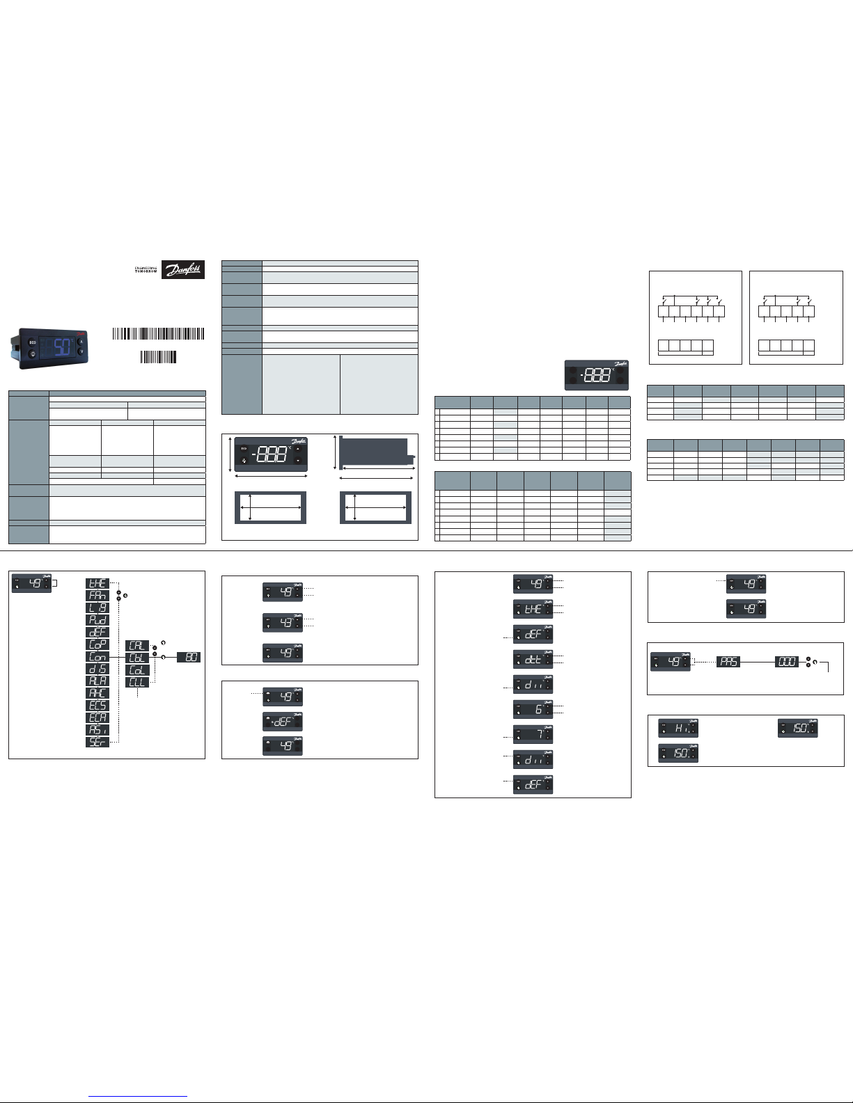
Technical specication
Menu structure Operation Changing the setpoint:
Two kinds of left buttons - see pictures 1. and 3.
Example of changing a parameter Turning ON/OFF the ECO function
Password protection
Acknowledging alarm
Activating manual defrost
Dimensions
Wiring diagram
Conguration of outputs
Conguration of inputsConguration of inputs
ERC front and button functionality
Functional description of used sensors
Front mounting
(Lock with frame)
Rear mounting
(Lock with clips)
Relay
outputs
Compress. Defrost Fan Light Alarm
Heating
application
DO1 (o1C)
DO2 (o2C)
DO3 (o3C)
DO4 (o4C)
Input/
sensor
Cabinet
sensor
Evapor.
sensor
Conden.
sensor
Door
sensor
Light
sensor
Movem.
sensor
Comm.
S1
S2
S3
S4
di
Control temperature sensor
The control sensor must always be connected and is used for controlling the cut-in and cut-out of
the compressor according to the set-point. The sensor is also used for the displayed temperature.
Most common placement is in the return air to the evaporator.
Evaporator sensor
The evaporator sensor is only used for de-icing of the evaporator and has no control purpose.
Place the sensor where the ice melts last.
Please be aware of that sharp fins can damage the cable.
Condenser temperature sensor
The condenser sensor is used to protect the compressor against high pressure when the
condenser is blocked or the condenser fan fails.
Place the sensor at the liquid side of the condenser. Use a metal bracket or metal tape to ensure
good thermal conductivity. Be sure that the cable does not pass hot spots at the compressor or
condenser that exceeds 80 °C.
Congurable functionality
Button
Basic
function
Not
operating
ON/OFF
Increase
setpoint
Decrease
setpoint
Toggle
defrost
Toggle
light
1 press OK
1 pess and hold
2 press BACK
2 pess and hold
3 press UP
3 pess and hold
4 press DOWN
4 pess and hold
Congurable functionality
Button
Toggle
ECO
Toggle
pulldown
Increase
display
intensity
Decrease
display
intensity
Toggle °C
or F
Info menu
1 press
1 pess and hold
2 press
2 pess and hold
3 press
3 pess and hold
4 press
4 pess and hold
Press and
hold 5 sec to
access the
menu
1. Parameter group
1. Parameter name
Lower left button
Lower left button
Scroll through parameters
Scroll through menu group
The display shows the current temperature
Current temperature
1.
1.
2.
2.
3.
3.
Flashing temperature setpoint
Press: UP/DOWN to adjust setup
After 30 seconds, the display automatically
reverts to showing the current temperature
Defrost symbol is shown in defrost mode
Defrost symbol will disappear after the defrost is
finished.
(The dEF text during the defrost is displayed or
not based on the cabinet manufacturer settings)
Press briefly
to start or
stop defrost
1.
2.
3.
4.
5.
6.
7.
8.
9.
Press and hold 5 sec to access
the menu
Press: UP / DOWN to scroll
through the menu
Press: UP / DOWN to find the
desired parameter
Press: UP / DOWN to enter the
desired value
To select: press the lower
left button (OK)
To confirm: press the lower
left button (OK)
To accept: press the lower left
button (OK) and return to
parameter name
To exit without accept:
press the upper left button (BACK)
To return to parameter group:
press upper left button (BACK)
To return to menu:
press upper left button (BACK)
After 30 seconds of inactivity,
the display automatically
reverts to showing the current
temperature
Scroll through parameters group
Scroll through group "dEF" parameters
1.
2.
The green ECO symbol is list
when in ECO mode
Press briefly to enter
ECO mode
Password protection on three levels:
LEVEL 1: shop (daily use by shop personnel)
LEVEL 2: ser (service technician)
LEVEL 3: OEM (OEM programming
Press and hold 5
sec to access the
menu
1.
2.
The alarm code flashing alternately
with the temperature and the
alarm symbol is displayed
After the acknowledge the
temperature is displayed and the
alarm symbol remains shown
Press any button to acknowlege
Page 2
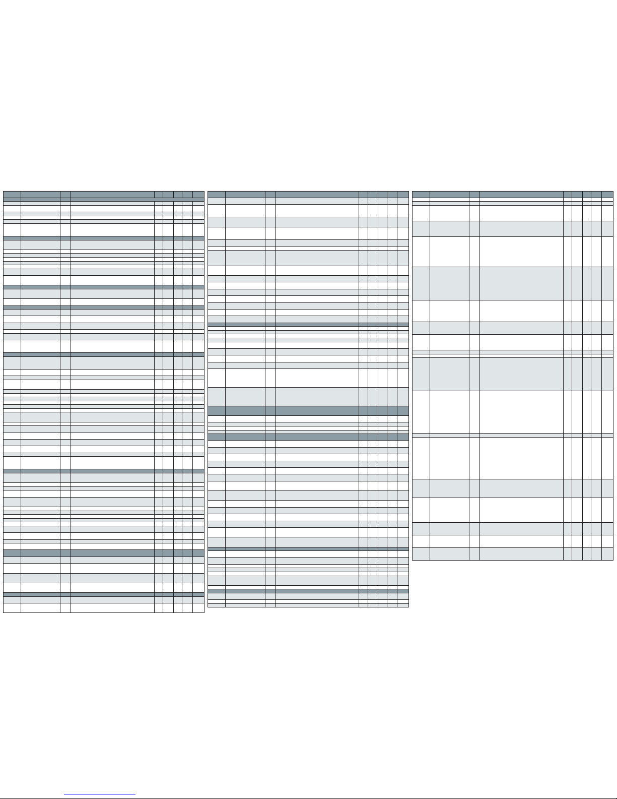
Parameter table
Menu Parameter name
Menu
code
Description Def Min Max Unit
Current
setting
Thermostat tHE Main menu for thermostatic settings
Set point SEt Set point value 2.0 -100.0 200.0 °C
Set point adjustment ratio SPr
Actual value of setpoint
adjustment = diF * SPr
0.5 0.0 1.0
Differential diF Thermostat differential for serving 2.0 0.0 20.0 K
High Set point HSE High limitation of thermostat setpoint in position warm 50.0 -100.0 200.0 °C
Low Set point LSE Low limitation of thermostat setpoint in position cold -35.0 -100.0 200.0 °C
Initial cut in iCi
Comp relay action when Tair is between Cut-in and Cut-out at
power-up
yES: Cut in the compressor
no: Cut out the compressor
no no yES
Fan FAn Main menu for fan settings
Fan control method FCt
FAo: Fan always on
SEt: Fan follow compressor by manually settings
Aut: Automatical Fan control
FAo FAo Aut
Fan On Delay Fod Delay for fan start after compressor cutin 0 0 240 Sec
Fan Stop delay FSd Delay for fan stop after compressor cutout 0 0 240 Sec
Fan On Cycle FoC On time for fan during compressor off period 0 0 960 Sec
Fan Stop Cycle FSC Stop time for fan during compressor off period 0 0 960 Sec
Fan Minimum Stop time FSt Minimum Stop time for fan protection 10 0 960 Sec
Δt for fan to cut in FdC
Delta T for fan to cut in which the temperature offset comparing
with thermostat cut in temperature
0.0 -10.0 10.0 K
Fan delay on door open Fdt
0: Fan stop immediately when door open
1~998: delay for fan stop after door open
999: fan keep running all the time during door opening
0 0 999 Sec
Light Lig Main menu for Light settings
Cabinet Light Control Source CLC
on: Always ON (Button is default to control light for all these options)
oFF: Always OFF
dor: Door sensor only
on on dor
Light off delay Lod
Delay to turn off the cabinet light after door close
0: No delay
0 0 300 Sec
Pull Down Pud Main menu for pull-down settings
Pull-down Initiate Temperature Pit
Temperature measured by control-sensor that will trigger the
pull-down mode
50.0 -40.0 50.0 °C
Pull-down Cycling PCy
The duration of the thermostatic operation at pull-down mode
The periode will start first time the controller reaches the PCt
30 0 360 min
Pull-down defrost Interval Pdi
Defrost interval during pull-down
Over-rules the defrost interval in normal mode
15 0 48 hour
Pull-down duration Pdd Max time for pull-down mode from initiated till terminated 24 0 48 hour
Pull-down limit temp PLt
The calculated cutout temp for pulldown mustn't lower than this
limit to prevent freezing of product
0.0 -55.0 55.0 °C
Pull-down reduction temp Δt Prt
This progressive temp value is used for calculating cutin temp and
cutout temp for Pull-down mode:
Pulldown-Cutin = NormalCutin - Δt * Hours
Pulldown-Cutout = NormalCutout - Δt * Hours
0.1 0.0 10.0 K
Defrost dEF Main menu for Defrost settings
Defrost type dFt
no: Defrost function is disabled
nAt: Natural defrost. time defrost
EL: Electrical heater
Hgd: Hot gas defrost
no no Hgd
Adaptive defrost Add
no: Defrost controlled by time
yES: Automatic defrost control activated
no no yES
Def terminate temp dtt Defrost stop temperature 6.0 0.0 25.0 °C
Def reset temp drt
Defrost timer reset temperature
0-199: normal evaluation between evaporator/air temp and drt
200: disable drt function
5.0 0.0 200.0 °C
Def Min Interval dii Minimum Interval between defrost starts 6 1 96 hour
Def Max Interval dAi Maximum Interval between defrost starts 7 1 96 hour
Def Min Time dit Minimum defrost time 5 0 240 min
Def Max time dAt Maximum defrost time 30 0 480 min
Drip off time dot Drip off delay time 0 0 60 min
Fan delay after Defrost Fdd Delay for fan start after defrost 0 0 600 sec
Fan start Temp Ftd
Fan start temperature after defrost. it's based on evaporator
temperature.
This only applies if an evaporator temperature sensor is fitted
25.0 -25.0 25.0 °C
Defrost Fan on dFA Fan cutin during defrost no no yES
Defrost on compressor time dCt
no: Elapsed time
yES: Accumulated compressor run time
no no yES
Defrost by compressor
running time
doC
Continuous compressor running can cause defrost
0: Deactived
0 0 24 hour
Defrost start evaporator
temperature
dEt Defrost start trigger for adaptive defrost -50.0 -50.0 0.0 °C
Defrost Δt ddt
Defrost Δt compare with evporator temperature of first cut out
after defrost to trigger defrost start
5.0 0.0 30.0 K
Initial Defrost Interval idi First time defrost after power-up 3 0 96 hour
Initial Defrost Duration idd
Determine defrost or not while startup by relay1 counter
0: Disable idi function
1-998: Normal evaluation between idd and relay 1 counter
999: idi is always enabled
100 0 999 c ycle
Compressor CoP Main menu for Compressor timer settings
Voltage protection uPt
no: No voltage protection
yES: Voltage protection activated based on voltage related
settings
no no yES
Minimum Cutin voltage uLi Compressor must not be cut in if power supply goes lower than 0 0 270 Vac
Minimum cut-out voltage u Lo Compressor must be cut out if power supply goes lower than 0 0 270 Vac
Maximum voltage uHi
Maximum supply voltage for the compressor to postpone startup
or stop at
270 0 270 Vac
Sensor Error Type EHd
no: No sensor error handling
SEt: In case of control sensor error, follow error run/stop time
Aut: Automatical Sensor error handling
no no Aut
Error run time Ert Run time for compressor in case of control probe error 0 0 60 min
Error stop time ESt Stop time for compressor in case of control probe error 1 0 60 min
Min Stop time CSt Minimum OFF time for compressor 2 0 30 min
Min run time Crt Minimum ON time for compressor 0 0 30 min
Max Off time Cot Maximum OFF time for compressor 0 0 480 min
Compressor door open delay Cdd
Door open delay to stop compressor
0: Disable
0 0 15 min
System resume after door
open
Srt
Fan and Compressor resume after cut out by door open
0: Disable
0 0 60 min
Power On Delay Pod Delay time from power on until the outputs are activated 300 0 300 Sec
Power-on temperature Pot
If Air temperature at power up is higher than this, power on delay
is overruled
-100 -100 200 °C
Condenser
Protection
Con Blocked condenser protection.
Condenser Alarm Limit CAL
Alarm limit for condenser temperature
Available only if condensor sensor is attached / assigned
80 0 200 °C
Condenser Block Limit CbL
Stop limit. If this temperature is exceeded, compressor must be
stopped
Available only if condensor sensor is attached/assigned
85 0 200 °C
Condenser OK limit CoL
OK limit. Compressor is allowed to start again if the condenser
temperature is lower than this temperature
Available only if condensor sensor is attached / assigned
60 0 200 °C
Condenser Low Temp. Limit CLL
Low limit. Compressor is not allowed to start if the condenser
temperature is lower than this temperature
Available only if condensor sensor is attached / assigned
-5 -100 20 °C
Display diS Display settings
Display intensity auto control diC
no: Display intensity use fixed value
yES: Display intensity controlled automaticlly by ambient light
no no yES
Display Intensity din
Normal Intensity of display when no ambient light sensor is
attached
Minimum intensity when ambient light sensor is attached
10 2 10
Menu Parameter name
Menu
code
Description Def Min Max Unit
Current
setting
Display Unit CFu
C: Celsius
F: Fahrenheit
-C -C -F
Temp sensor to display trS
SCo: Temperature control
EuA: Evaporator temperture
Con: Condenser temperature (Condenser cleaning)
AuS: Only for showing on display
SCo SCo AuS
Display Resolution rES
0.1: Decimal with 0.1 degree resolution
0.5: Decimal with 0.5 degree resolution
1: Integers
0.1 0.1 1
Display Range Limit rLt
no: Disabled. display is allowed to go outside of
’ThSP - diF*SPr ~ ThSP + diF* (1 - SPr)’
yES: Enabled. display is not allowed to go outside of
’ThSP - diF*SPr ~ ThSP + diF*(1 - SPr)'
no no yES
Display Delay ddL
Time-constant for averaging of temperature at display
Temp value reaches 100 % when 5 * ddL expires
0 0 10 min
Display Offset doF Correction for bad sensor placement. Value at 0 °C 0.0 -10.0 10.0 K
Lock-time After defrost dLt
In order not to show a rising temperature during defrosting, the
displayed temperature is locked at the temperature shown at the
start of the defrost cycle for the number of minutes set in this
parameter
0: No lock
15 0 60 min
Show Economy/Night Mode SEC
no: "ECo" and "ngt" will not be showed for Economy / Night Mode
yES: "ECo" or "ngt" will be displayed through whole
Economy / Night Mode
no no yES
Show Pull Down SSC
no: "SC" will not be showed for Pull down state
yES: "SC" will be displayed through whole Pull down state
no no yES
Show Holiday SHo
no: Display will show temperature or ECO mode during holiday mode
yES: Display will show "HoL" during holiday mode
no no yES
Show Defrost SdF
no: Display will show temperature during defrost
yES: Display will show dEF during defrost
yES no yES
Show compressor symbol SCS
no: Compressor symbol will not show on display
yES: Show compressor symbol on display
yES no yES
Show Fan symbol SFS
no: Fan symbol will not show on display
yES: Show fan symbol on display
yES no yES
Show Defrost symbol SdS
no: Defrost symbol will not show on display
yES: Show defrost symbol on display
yES no yES
Show ECO symbol SES
no: ECO symbol will not show on display
yES: Show ECO symbol on display
yES no yES
Alarm ALA Main menu for alarm settings
High Temp Alarm HAt High alarm limit 15.0 -100.0 200.0 °C
Low Temp Alarm LAt Low alarm limit -50.0 -100.0 200.0 °C
High Alarm delay Htd Alarm delay time for high-temperature alarm 30 0 240 min
Low Alarm delay Ltd Alarm delay time for low-temperature alarm 0 0 240 min
Pulldown delay Pdd
Alarm delay time during & after defrost and after power up
(Only for high-temp. alarm)
240 0 960 min
Door Open delay dod
Alarm delay on open door Alarm
0: Disable
2 0 60 min
Voltage alarm uAL
no: No voltage alarm
yES: Voltage alarm activated
no no yES
Leakage alarm LEA
Leakage detection for compressor protection
0: Disable
0 0 96 hour
Alarm Buzzer Duration Abd
0: Buzzer is off
[0. 999]: Buzzer will continue for the time set by the parameter
in minutes in which process the sound format is such as
IIIIIIII______________________IIIIIIIIII_____
999: Buzzer continues for ever with
IIIIIIIII______________________IIIIIIIIII__________ and so on
0 0 999 min
Auto Clearance of Alarm ACA
no: Disable this function; alarm status will not disappear
automatically without acknowledge by user even if the alarm
recovers
yES: Enable this function; alarm status can change from active to
inactive automatically on condition that the alarm recovers
(Errors are always auto-clearance enabled)
yES no yES
AutoHeater
Control
AHC
Main menu for Street cooler settings
(Street-Cooler : Coolers placed in the street with frost
protection )
Automatic heater mode
enable
AuH
yES: Heater will be active if air-temperature is too low
no: Normal operation
no no yES
Energy mode delay End Delay between heater and compressor operation 60 0 360 min
Auto Heat set point AHS Heater Set point: the set point of auto heating 2.0 -100.0 200.0 °C
Auto heat differential AHd Thermostat differential for auto heatting 2.0 0.0 20.0 K
ECO
strategy
ECS Main menu for ECO strategy
ECO on / off ECo
Eco active or not
If no all other settings are not active
yES no yES
Door Actions EdA
Times of door action to trigger exiting ECO
(Only can be accessed by Danfoss)
1 1 10
Pir Actions EPA
Times of PIR action to trigger exiting ECO
(Only can be accessed by Danfoss)
1 1 10
Action counter time ECt
Door action or PIR action within action counter time can trigger
exiting ECO (Only can be accessed by Danfoss)
30 0 180 min
Door delay Edd
Door delay after door close to trigger entering ECO
(Only can be accessed by Danfoss)
180 0 180 min
Pir delay EPd
PIR delay to trigger entering ECO
(Only can be accessed by Danfoss)
120 0 180 min
Shop Light Day SLd
Shop light level during opening hours
When above this level ECO mode is canceled
Disabled if no light sensor connected/assigned
5 0 80
Shop Light Night SLn
Shop light level during closing hours
When below this level ECO mode is enabled
Disabled if no light sensor connected/assigned
3 0 80
Time to pull down tto
Time which ERC stay in ECO and holiday mode to decide to enter
Pull down or Serving mode
0 0 168 hour
Light Source delay on ECO LSd
Time delay for light source to change from serving mode source
to ECO mode source
0 0 180 min
EWU active
on / off
Euu Enable or disable early wake up yES no yES
Shop close hour CLH
Shop is assumed to be closed when staying in ECO mode longer
than shop close hour
6 0 24 hour
Early wake up time offset ErL
Time of exiting ECO mode for next
day: Time of first activity to exit ECO mode - the Early wake-up time
0: Early wake up function disabled
120 0 240 min
Holiday Length HoL
In case that no activity has been registered for a number of days
specified by the Holiday, the Early-wake-up is deactivated and the
cooler must stay in Holiday mode until activity is detected
72 0 999 hour
ECO manag. ECA Main menu for ECO management
ECO Temperature Offset Eto
If this offset is below zero, it means that Night mode will be
activated instead of ECO mode
4.0 -25.0 25.0 K
Holiday Temperature Offset Hto
Increase or decrease of temperature with respect to normal mode
during Holiday mode
6.0 -25.0 25.0 K
ECO Differential diE Thermostat differential for ECO 2.0 0.0 10.0 K
ECO Fan on cycle FoE On time for fan during compressor off period in ECO mode 0 0 960 Sec
ECO Fan stop cycle FSE Off time for fan during compressor off period in ECO mode 0 0 960 Sec
ECO Cabinet light control ELC
on: Always ON (Button is default to control light for all these options)
oFF: Always OFF
dor: Door sensor only
on on dor
Eco Light delay ELd Delay from shop light is turned on or off till mode shift is allowed 5 0 10 min
Assign. ASi Assignment of inputs and outputs
MODBUS Safety uSA
no: MODBUS auto detection is enabled
yES: MODBUS communication is deactivaed
no no yES
Temp Adj. for S1 t1A Adjust value for sensor1 before being used by application 0.0 -20.0 20.0 K
Temp Adj. for S2 t2A Adjust value for sensor2 before being used by application 0.0 -20.0 20.0 K
Menu Parameter name
Menu
code
Description Def Min Max Unit
Current
setting
Temp Adj. for S3 t3A Adjust value for sensor3 before being used by application 0.0 -20.0 20.0 K
Temp Adj. for S4 t4A Adjust value for sensor4 before being used by application 0.0 -20.0 20.0 K
S1/S2/S3 Config
S1C
S2C
S3C
Sensor type used for sensor input 1/2/3
Stn: Standard NTC 5k @ 25 °C (EKS211) in Celsius
Htn: High temperature NTC 100k @ 25 °C in Celsius
Ldr: Light sensor(LDR). Luminens
dig: Digital input. On / Off
Stn Stn dig
S4 Config S4C
Stn: Standard NTC 5k @ 25 °C (EKS211). in Celsius
Htn: High temperature NTC 100k @ 25 °C. in Celsius
Pt1: PT1000 sensor 1000K @ 0 °C. in Celsius
Ldr: Light sensor(LDR). Luminens
dig: Digital input. On / Off
Stn Stn dig
S1/S2/S3 Application
S1A
S2A
S3A
Select the function to be controlled via the Sensor 1 / 2 / 3
nC: Not connected
SCo: Temperature control
EuA: Evaporator temperture
Con: Condenser temperature (Condenser cleaning)
AuS: Only for showing temperature on display
Ldr: Light sensor(LDR). Luminens
ECo: External input to control ECO mode
doC: Door contact. Contact closed when door closed
doo: Door contact. Contact open when door closed
SCo nC doo
S4 Application S4A
Select the function to be controlled via the Sensor 4 input
nC: Not connected
SCo: Temperature control
EuA: Evaporator temperture
Con: Condenser temperature (Condenser cleaning)
AuS: Only for showing temperature on display
Ldr: Light sensor (LDR). Luminens
ECo: External input to control ECO mode
doC: Door contact. Contact closed when door closed
doo: Door contact. Contact open when door closed
bt5: Button5
nC nC bt5
DI Config diC
Select the function to be controlled via the digital I/O
non: Not used. (If communication is available depending on
MODBUS safety)
doC: Door contact. Contact closed when door closed
doo: Door contact. Contact open when door closed
ECo: External input to control ECO mode
Pir: Movement sensor (Passive infrared)
non non Pir
DO1 Config o1C
CoP: Compressor (With ZeroCrossing)
PiC: Pilot compressor (No ZeroCrossing)
HEt: Inverse output. Heating application (With ZeroCrossing)
PiH: Pilot Heat relay (No ZeroCrossing)
CoP CoP PiH
DO2 Config o2C
no: Not used
dEF: Electric defrost heater / Valve for hot gas
ALA: Alarm output
FAn: Fan control
Lig: Light control
dEF 0 Lig
DO3 Config o3C Same as DO2 Config FAn 0 Lig
DO4 Config o4C Same as DO2 Config Lig 0 Lig
Button 1 Short Config
b1C
b2C
b3C
Config of key 1 short. Lower left
noP: Not operating
tP: Increase Setpoint
tn: Decrease setpoint
ECo: Toggle Eco mode
Lig: Toggle light
dEF: Toggle defrost
SuP: Toggle Super-Cool /Pull-down
diP: Increase display intensity
din: Decrease display intensity
CFA: Toggle Celsius and Fahrenheit
noP noP CFA
Button 1 Long Config
b1L
b2L
b3L
Config of key 1 long. lower left
noP: Not operating
tP: Increase Setpoint
tn: Decrease setpoint
ECo: Toggle Eco mode
Lig: Toggle light
dEF: Toggle defrost
SuP: Toggle Super-Cool /Pull-down
diP: Increase display intensity
din: Decrease display intensity
CFA: Toggle Celsius and Fahrenheit
PoF: ERC power ON/OFF
HoL: Enter holiday mode
inF: Enter Info menu
PoF noP InF
Button 4 Short Config b4C Config of key 4 short. Lower right. As key 1 short tn noP C FA
Button 4 Long Config b4L
Config of key 4 long. Lower right
noP: Not operating
tP: Increase Setpoint
tn: Decrease setpoint
tn: Decrease setpoint
ECo: Toggle Eco mode
Lig: Toggle light
dEF: Toggle defrost
SuP: Toggle Super-Cool /Pull-down
diP: Increase display intensity
din: Decrease display intensity
CFA: Toggle Celsius and Fahrenheit
PoF: ERC power ON/OFF
HoL: Enter holiday mode
Lig noP HoL
Button 5 Short Config b5C
Config of key 5 short. Lower right
noP: Not operating
ECo: Toggle Eco mode
SuP: Toggle Super-Cool / Pull-down
Lig: Toggle light
dEF:Toggle defrost
noP noP dEF
Button 5 Long Config b5L
Config of key 5 long. Lower right
noP: Not operating
ECo: Toggle Eco mode
SuP: Toggle Super-Cool / Pull-down
Lig: Toggle light
dEF: Toggle defrost
PoF: ERC power ON / OFF
HoL: Enter holiday mode
noP noP HoL
Pass-word level1 PS1
Shop owner
Most common parameters for instance real time clock. day / night
mode etc.
0: Disabled
0 0 999
Pass-word level2 PS2
Service technician
all parameters with read permission and possibility to change a
number of parameters like defrost, fan etc.
0: Disabled
0 0 999
Pass-word level3 PS3
OEM Customer
All parameters read and write permission. But with some
restriction to for instance reset statictical information
0: Disabled
0 0 999
Danfoss can accept no responsibility for possible errors in catalogues, brochures and other printed material. Danfoss reserves the right to alter its products without notice. This also applies to products
already on order provided that such alterations can be made without subsequent changes being necessary in specifications already agreed. All trademarks in this material are property of the property
of the respective companies. Danfoss and Danfoss logotype are trademarks of Danfoss A/S. All rights reserved.
 Loading...