

Page 1
User Guide
Bottle cooler controller
ERC 111
This reference manual is intended to be used primarily by OEMs for the purposes
of programming ERC 111. It may also be useful for technicians. It is not intended as
a user guide for end users.
www.danfoss.com/erc
Page 2
User Guide | ERC 111 Refrigeration Controller
Introduction
Application
Advantages
Approvals
Temperature control for refrigeration appliances.
Front panel mounting.
The latest generation CPU, plenty of memory
and high-end electronic components allow for
a uniquely versatile software. Three separate
password-protected user levels can be used to
control more than 300 different parameters to fit
all individual requirements.
R290/R600a end-use applications employing in
accordance to EN/IEC 60335-2-24, annex CC and
EN/IEC 60335-2-89, annex BB
Glow wire according to EN/IEC 60335-1;
IEC/EN 60730;
UL60730;
NSF,
CQC;
GOST R 60730.
Password protected
The access level can be set separately for each
parameter using "KoolProg Software".
There are three levels of access 1, 2, 3:
- level 1 is for shop access;
- level 2 for technicians;
- level 3 for OEMs.
The access levels cannot be set using the buttons.
Passwords for the different levels can however be
altered for the level of access you have,
e.g. a level 2 user can change the password for
level 1 and level 2 but not level 3.
2 | BC227086437558en-000702 © Danfoss | DCS (vt) | 2019.07
Page 3
User Guide | ERC 111 Refrigeration Controller
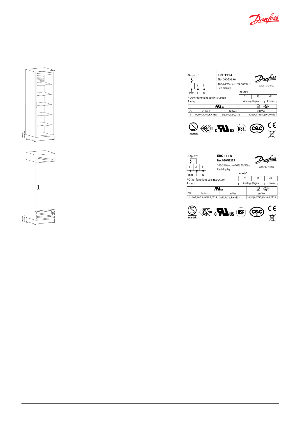
Typical application
Glass Door Merchandiser
Gastro cooler
© Danfoss | DCS (vt) | 2019.07 BC227086437558en-000702 | 3
Page 4
User Guide | ERC 111 Refrigeration Controller
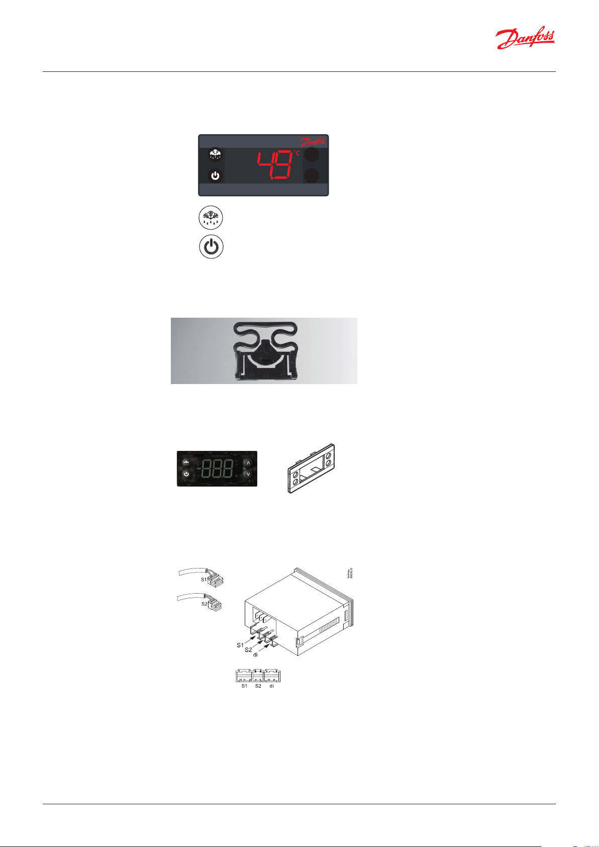
Product overview
Display
^
^
Buttons
Clips Are used to secure the controller in place in the
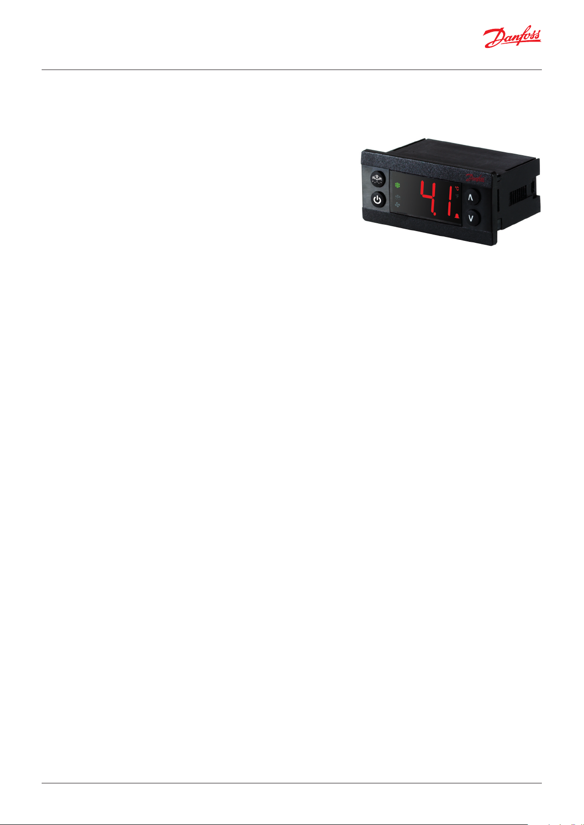
The ERC 111 is an electronic refrigeration
controller with an LED display especially
developed for bottle coolers and commercial
fridges and freezers. It is particularly suited for
OEM customers where time, easy and reliable
installation and high quality need to go hand in
hand with flexibility.
The display can be ordered in red or blue.
The controller is available with the upper left
button as "Defrost".
The lower left-button can be supplied with
"Stand by".
case of rear mounting. They are not used with
front mounting.
There are two identical clips, one placed on
either side of the controller.
Front frame
"S1"
Temperature sensor for
cabinet
"S2"
Temperature sensor for
defrost
At front mounting place the wired controller in
the hole. Then press the front frame in position.
The plastic lugs locks hereby the controller.
Controller without front frame Front fra me
Control temperature sensor
There are different lengths.
Defrost temperature sensor
Should be mounted on the evaporator.
The function of an input can be reprogrammed,
but the connector can not be moved.
The connector is designed to only one location.
"S1" to "S1", " S2" to "S2", etc.
4 | BC227086437558en-000702 © Danfoss | DCS (vt) | 2019.07
Page 5
User Guide | ERC 111 Refrigeration Controller
Quick programming
Software for PC
USB gateway
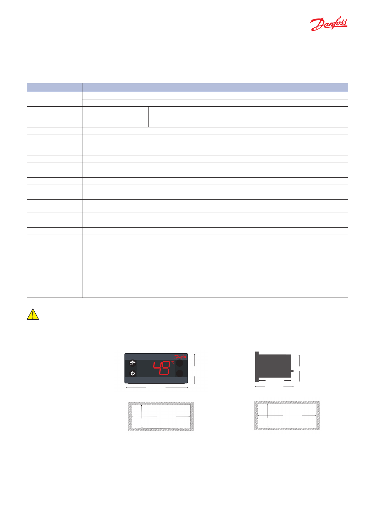
USB programming key
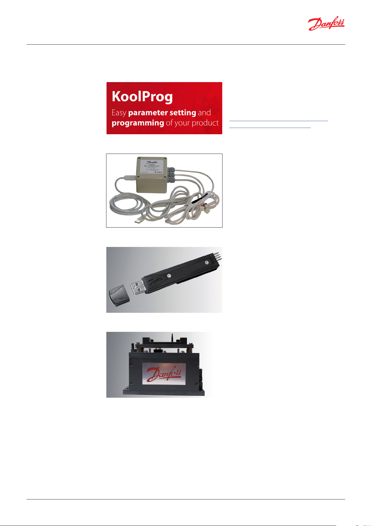
KoolProg
Software from Danfoss for programming the
ERC-controller via a PC rather than with the front
panel buttons.
https://www.danfoss.com/en/service-andsupport/downloads/dcs/koolprog/
USB gateway
The USB Gateway is a laboratory tool, offering
fast and easy programming of any ERC
controller connected directly to the PC.
"KoolProg Software" installation kit is provided
for the PC. The gateway is standard inventory
for OEM labs.
Programming an individual unit in a
laboratory
The USB key requires "KoolProg Software"
running on a PC. It enables parameters to be set
in real time and an array of status information to
be read (bidirectional connection).
Once the desired settings have been
determined, a specific parameter file is saved to
the USB key for later mass programming through
the docking station.
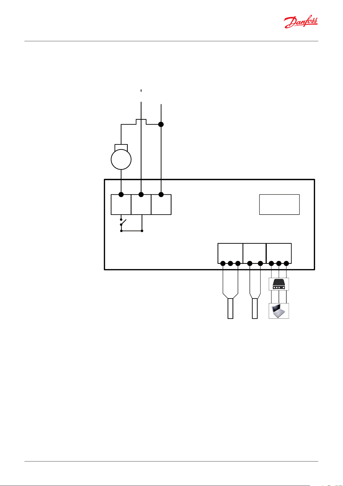
Docking station
© Danfoss | DCS (vt) | 2019.07 BC227086437558en-000702 | 5
Mass programming on an assembly line:
The docking station is used for high volume
programming of ERC controllers, for example on
an assembly line. The docking station is a
write-only device.
The USB key, is to be inserted into the docking
station. The settings are then loaded into each
successive controller in a matter of seconds.
"KoolProg Software" is not required for mass
programming.
Page 6
User Guide | ERC 111 Refrigeration Controller
Technical specs
Power Supply 100 - 240 V AC Switch mode power supply. Average 0.7 W
Input
Output
Probes Danfoss NTC sensors and Danfoss ERC accessories
Connectors
Programming Programming with Danfoss KoolProg PC software, Docking station and Programming key
Assembly Front mounting; brackets; fully integrated solution (requires OEM specific design of mounting hole)
Display LED display, 3 digit, decimal point and multi functionality icons; °C/°F scale
Keypad 4 buttons (integrated IP65 design), 2 left, 2 right; user programmable
Operating Conditions 0 °C to 55 °C, 93% rH
Storage Conditions -40 °C to 85 °C, 93% rH
Range of Measurement -40 °C to 85 °C
Protection
Environmental Pollution degree II, non-condensing
Resistance to heat & fire Category D (UL94-V0)
EMC category Category I
Operating Cycles Compressor relay: more than 175,000 at full load (16A(16A))
Approvals
3 inputs: 2 analogue (digital), 1 digital; user specific assignment
• Air/evaporator/condenser
UL60730 EN60730
"DO1" (Compressor relay)
120 V AC: 16 A resistive/FLA16/LRA72
240 V AC: 10 A resistive/FLA10/LRA60
16(16) A
Modular connector system for OEM customers, with optional output screw terminal adapter;
Input connector type: Rast2 5 Edge connectors; output connector type: RAST 5 standard
Front: IP65
Rear: water and dust protection corresponds to IP31, accessibility of connectors limit rear part rating to IP00
R290/R600a end-use applications employing in
accordance to EN/IEC 60335-2-24, annex CC and EN/
These approvals are only valid when using the accessories listed in
this document
IEC 60335-2-89, annex BBGlow wire according to EN/
IEC 60335-1
IEC/EN 60730
UL60730
NSF
CQC
GOST R 60730
IMPORTANT NOTE
The inputs are not galvanic separated and are connected directly to the mains supply!
For that reason, door-switches, sensors as well as the cables must fulfil the reinforced insulation requirements.
Dimensions
^
36,5 mm
^
47,25 mm
78,25 mm
71 mm
28,5 mm
Front mounting
(Lock with frame)
51,25 mm
30 mm
Rear mounting
(Lock with clips)
28 mm
71 mm
6 | BC227086437558en-000702 © Danfoss | DCS (vt) | 2019.07
Page 7
User Guide | ERC 111 Refrigeration Controller
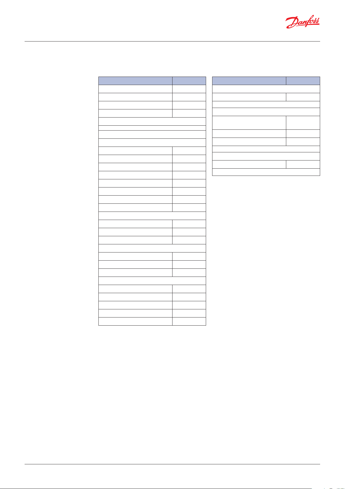
Connections
100 –240 VAC SMPS
Compressor
1 32
DO1
L
N
DO’s
ERC111A
Controller
diS1 S2AI/DI’s
Cabinet temp. sensor
Evaporator or condenser
temp. sensor
Gateway
Optional PC
communicaton
© Danfoss | DCS (vt) | 2019.07 BC227086437558en-000702 | 7
Page 8
User Guide | ERC 111 Refrigeration Controller
Code numbers
Type Code no. I-Pack
ERC 111, Red LED, without buzzer 080G3230
ERC 111, Blue LED, without buzzer 080G3231
ERC 111, Red LED, with buzzer 080G3235
ERC 111, Blue LED, with buzzer 080G3236
Version with buzzer is available only on demand
Temperature sensors
-40 – 85 °C, PVC Standard, NTC 5 K
S1, 470 mm, 3-pole 077F8751
S1, 1000 mm, 3-pole 077F8757
S1, 1500 mm, 3-pole 077F8761
S1, 2000 mm, 3-pole 077F8765
S1, 2200 mm, 3-pole 077F8767
S1, 3000 mm, 3-pole 077F8769
S1, 3500 mm, 3-pole 077F8723
S1, 6000 mm, 3-pole 080G2019
-40 – 120 °C, TPE precision NTC 5 K, Santroprene
S1, 1500 mm, 3-pole 077F8726
S1, 2000 mm, 3-pole 077F8727
S1, 3000 mm, 3-pole 077F8729
-20 – 175 °C, Silicone rubber cable, NTC 100 K
S1/S3, 1000 mm, 3-pole 080G2041
S1/S3, 2000 mm, 3-pole 080G2043
S1/S3, 3000 mm, 3-pole 080G2045
-40 – 85 °C, PVC Standard, NTC 5 K
S2, 1000 mm, 2-pole 077F8786
S2, 1500 mm, 2-pole 077F8790
S2, 2000 mm, 2-pole 077F8794
S2, 3000 mm, 2-pole 077F8798
S2, 6000 mm, 2-pole 080G2029
Type Code no. I-Pack
Clips
Black (2 needed per controller) 080G3308
Programming
OEM Docking station, production
line
Programming key EKA183A 080G9740
Gateway incl USB Cable for R&D 080G9711
Power Plug*
3-pole with screw 080G3356
*available optional plugs with screw connection are limited to 16A
080G9701
NOTE: For more information about temperature sensor
Sx (di)= connector position.
Inputs are configurable.
types and connectors, please refer to Danfoss’ technical
brochure "NTC type temperature sensors for ETC & ERC
controllers".
8 | BC227086437558en-000702 © Danfoss | DCS (vt) | 2019.07
Page 9

User Guide | ERC 111 Refrigeration Controller
Operation
KoolProg Software/Gateway
Docking station
Manual operation with
buttons (Direct Access)
Examples
The controller can be controlled in three ways:
Using "KoolProg Software", the Danfoss Docking
Station or manually by means of the buttons on
the front panel.
"KoolProg Software" is licenced Danfoss software
offering easy parameter set up via a USB gateway.
This software is supplied separately;
for technical literature and further information,
please contact your local Danfoss representative.
Docking station is supplied separately.
For further information, please contact your local
Danfoss representative.
1 Press: variable direct
function, e.g. defrost
Sub function: “back”
1 Press: variable direct
function, e.g. ON/OFF
Sub function: “OK”
Changing the Desired Temperature Set point:
1. The display shows the current temperature.
2. Press "up/down" to access set point.
3. Press "up/down" to adjust set point.
After 30 seconds, the display automatically
reverts to showing the current temperature
Acknowledging Alarms:
1. Display Flashing the alarm message.
2. Press any button to acknowlege.
Password protection:
1. Press "up/down" and hold 5 seconds to access
the menu.
2. The display shows "PAS".
3. Press "OK".
4. Press "Up/Down" to the code.
5. Press "OK".
Password protection on three levels:
1. Level 1: "shop" (daily use by shop personnel).
2. Level 2: "ser" (service technician).
3. Level 3: "OEM" (OEM programming).
1 Press: temperature set point
Sub function: “up”
^
^
1 Press: temperature set point
Sub function: “down”
Changing a Parameter
Some parameters may be hidden to you.
When scrolling through menus, the parameters
available will have been pre-determined using
"KoolProg Software".
Your access level will determine which
parameters you can view and edit:
1. Press "up/down" and hold 5 seconds to access
the menu.
2. First parameter group is shown "tHE".
3. Press "up/down" to find the desired group.
4. Press "OK".
5. First parameter is shown.
6. Press "up/down" to find the desired
parameter.
7. Press "OK".
8. Press "up/down" to find the desired setting.
9. Press "OK".
After 30 seconds, the display automatically
reverts to showing the current temperature.
Or Press 2 x "Back".
NOTE:
Incorrect parameter settings can lead
to inadequate cooling, excessive energy
consumption, unnecessary alarms and in the
case of temperature-sensitive food storage,
breaches in food hygiene principles and
regulations.
Only a trained operator should make changes to
parameters.
© Danfoss | DCS (vt) | 2019.07 BC227086437558en-000702 | 9
Page 10

User Guide | ERC 111 Refrigeration Controller
Menu/functions
ERC menu code Description
"tHE Thermostat settings
"SEt"
Min. -100.0°C
Max. 200.0°C
Default 2.0°C
"SPr"
Min. 0.0
Max. 1.0
Default 0.5
"diF"
Min. 0.0 K
Max. 20.0 K
Default 2.0 K
"HSE"
Min. -100.0°C
Max. 200.0°C
Default 50.0°C
"LSE"
Min. -100.0°C
Max. 200°C
Default -35.0°C
"iCi"
Min. no
Max. yes
Default no
Pud Pull Down settings
"PCy"
Min. 0 min
Max. 360 min
Default 30 min
"Pdi"
Min. 0 hour
Max. 48 hour
Default 15 hour
"Pdd"
Min. 0 hour
Max. 48 hour
Default 24 hour
"PLt"
Min. -55.0°C
Max. 55.0°C
Default 0.0°C
Set point
This parameter defines the desired temperature (set point)
In standard operation the set point is changed by simply pressing the
"temperature up/down" buttons on ERC 111; for laboratory and
assembly line you may opt for software controlled set point adjustment
(speed improvement)
Current set point adjustment value diF * SPr
The default value is set to 0.5 and the parameter is hidden by default.
"Spr" defines the position of the set point in relation to cut-in and cut-out
"Spr=0,5" sets the set point mid between cut-in and cut-out.
"Spr=0" sets the set point at the cutout. "Spr=1" sets the set point at cut-in
Thermostat differential
This defines the difference between the cut-out and the cut-in
The desired temperature is determined by "SPr" and "diF"
Upper limit of thermostat set point
Define the temperature range limit of the controller
Once set, the desired temperatue (set point) can not go above "HSE" or below "LSE"
Lower limit of thermostat set point
Define the temperature range limit of the controller
Once set, the desired temperatue (set point) can not go below "LSE"
Initial cut in
Comp relay action when Tair is between cut-in and cut-out at power-up:
"yES": cut in the compressor
"no": cut out the compressor
Pull down (sometimes known as Super Cool) is a procedure for improving
cooling performance, accelerating the time used to reach the desired
temperature. Pull down settings overrule all other settings.
Pull Down Cycling
This is the duration in minutes of the compressor cycling at the reduced
set point temperature. Once the desired pull down limit temperature
"PLt" has been reached during pull down, the compressor will continue to
cycle ON/OFF for the duration of "PCy". At the end of the period defined by
"PCy", the set point temperature will return to normal and pull down will
cease.
Pull Down Defrost Interval
Even though most applications do not need Defrost during pull down, an
extended defrost during pull down can be applied. This is the time
between defrost cycles during pull down. It is measured in hours and can
be up to 48 hours. During pull down, this setting overrides the defrost
interval and defrost time settings (see the defrost section).
Pull Down Duration
You can choose to limit the maximum pull down time. Once this time
value (max. 48 hours) is reached, pull down will stop regardless of
whether the desired pull-down temperature has been reached.
Pull Down Limit Temperature
This parameter sets the minimum allowed temperature during pull-down.
In order to protect valuable contents you must always specify the absolute
minimum temperature allowed in your application.
For glass door merchandisers 0°C/32°F protects bottles from freezing;
for commercial fridges you may opt for a slightly higher temperature
(e.g. 2°C)
10 | BC227086437558en-000702 © Danfoss | DCS (vt) | 2019.07
Page 11

ON ON
User Guide | ERC 111 Refrigeration Controller
dEF Defrost settings
"dFt"
Default no
Defrost Type
"no": defrost function is disabled.
"nat": OFF-cycle defrost (natural defrost).
"Add"
Min. no
Max. yes
Default no
"dtt"
Min. 0.0°C
Max. 25.0°C
Default 6.0°C
"drt"
Min. 0.0°C
Max. 200.0°C
Default 5.0°C
"dii"
Min. 1 hour
Max. 96 hour
Default 6 hour
"dAi"
Min. 1 hour
Max. 96 hour
Default 7 hour
"dit"
Min. 0 min
Max. 240 min
Default 5 min
"dAt"
Min. 0 min
Max. 480 min
Default 30 min
"dCt"
Min. no
Max. yes
Default no
"doC"
Min. 0 hour
Max. 24 hour
Default 0 hour
"dEt"
Min. -50.0°C
Max. 0.0°C
Default -50.0°C
Adaptive defrost
"no": defrost controlled by time.
"yES": automatic defrost control activated.
Terminate Temperature
This parameter defines at what temperature the defrost cycle will stop.
The temperature is given by the evaporator sensor or by the cabinet
temperature sensor if no evaporator sensor is used.
Defrost reset temperature
The defrost counter is saved and restored at power-up, but if the
temperature sensor, used for defrost, is higher than this value at
power-up, it is assumed that the evaporator is free of ice and the
defrost counter will be cleared.
Defrost minimum Interval/dii
Defines the minimum time period between the start of two defrost cycles.
Once the minimum interval has expired, the defrost cycle will start at
the following cut-out or once the maximum interval "dAi" has been
reached.
Maximum Interval
Defines the maximum time period between the start of two defrost cycles.
Minimum Time
Defines the minimum duration of a defrost cycle. During this period, the
controller will not check the temperature. Once the minimum time has
expired, the temperature will be checked and if the terminate temperature
"dtt" has been reached, the defrost cycle will end. If dtt has not been
reached, defrost will continue until either dtt is reached or the
maximum time "dAt" reached, whichever occurs first.
Maximum Time
Defines the maximum duration of a defrost cycle.
The controller will not allow a maximum time to be entered which is
less than the minimum time, or a minimum time which is more than the
maximum time.
Defrost ON Compressor Time
If this parameter is set to "yES", then defrost cycles are based on the total
time the compressor has been running.
If this parameter is set to no, then defrost cycles are related to elapsed
time, regardless of how long and how often the compressor has been on.
Defrost by Comp. running time
Continuous compressor running can cause defrost.
"0" = deactived
Defrost start evaporator temp
Defrost start trigger for adaptive defrost.
DEFROST CYCLE
© Danfoss | DCS (vt) | 2019.07 BC227086437558en-000702 | 11
Page 12

User Guide | ERC 111 Refrigeration Controller
"ddt"
Min. 0.0 K
Max. 30.0 K
Default 5.0 K
"idi"
Min. 0 hour
Max. 96 hour
Default 3 hour
Defrost Δt
Defrost Δt compare with evaporator temperature of first cut out after defrost
to trigger defrost start.
The defrost start if evaporator temperature has decreased
Initial Defrost Interval
The initial defrost interval determines the time for first defrost after
power-up. The initial defrost is mainly intended for factory testing of the
defrost functionality and can be set to expire after a number compressor
cycles according to the setting of parameter idd. During normal operation,
the defrost counter will be saved in memory and restored after power loss,
making the initial defrost unnecessary.
"idd"
Min. 0
Max. 999
Default 100
Initial Defrost Duration
The initial defrost duration is the number of compressor cycles before
the initial defrost is deactivated.
"0": "idi" No initial defrost.
"1-998": number of compressor cycles before deactivation.
"999": initial defrost always active.
CoP Compressor settings
"uPt"
Voltage protection
"no": no voltage protection.
Min. no
Max. yes
Default no
"uLi"
Min. 0 V AC
Max. 270 V AC
Default 0 V
"uLo"
Min. 0 V AC
Max. 270 V AC
Default 0 V
"uHi"
Min. 0 V AC
Max. 270 V AC
Default 270 V
"yES": voltage protection activated based on voltage related settings.
Minimum cut-in voltage/uLi. Minimum cut-out voltage/uLo.
Maximum voltage/uHi
These three parameters provide voltage protection to the compressor.
Start by setting "uHi", followed by "uLo" and "uLi".
"uLi": when the compressor is due to start, the voltage of the power
supply will be checked and the compressor will only be allowed to
start if it is at least the value given in this parameter.
"uLo": when the compressor is running, it will be switched
OFF if the voltage goes below that given in this
parameter.
"uHi": when the compressor is running, it will be switched
OFF if the voltage exceeds that given in this parameter.
If the compressor is already stopped, it will remain
switched OFF.
"EHd"
Default no
Sensor Error Type
"no": no sensor error handling.
"SEt": in case of control sensor error, follow error run/stop time.
"Aut": automatical sensor error handling.
"Ert"
Min. 0 min
Max. 60 min
Default 0 min
Error Run Time
The parameter only become active in the unlikely event of a broken
temperature sensor. It is used to run the application in safety mode.
At the same time the sensor error will be shown in the display.
"Ert" define the duration the compressor will run.
Example: "Ert=4" [min] and "ESt=16" [min] will provide an average cooling
system activity of 20%. Ert and "ESt" values are based on OEM experience
and are by default inactive.
"ESt"
Min. 0 min
Max. 60 min
Default 1 min
Error Stop Time
The parameter only become active in the unlikely event of a broken
temperature sensor. It is used to run the application in safety mode.
At the same time the sensor error will be shown in the display.
"ESt" define the duration the compressor will be "idle".
12 | BC227086437558en-000702 © Danfoss | DCS (vt) | 2019.07
Page 13

User Guide | ERC 111 Refrigeration Controller
"CSt"
Min. 0 min
Max. 30 min
Default 2 min
Minimum Stop Time
It determines the minimum number of minutes the compressor must
remain idle before a Temperature cut-in can take effect. For example,
if the temperature sensor indicates that the cut-in temperature has been
reached, but the number of minutes set in this parameter have not elapsed
since the compressor last stopped, then the compressor will stay OFF.
It will only start once the duration given by "CSt" has been reached
provided the temperature is still high enough. "CSt" thus overrides the cut-in.
"Crt"
Min. 0 min
Max. 30 min
Default 0 min
Minimum Run Time
It determines the minimum number of minutes the compressor must run
before a Temperature cut-out can take effect. For example, if the
temperature sensor indicated that the cut-out temperature has been
reached, but the number of minutes set in this parameter have not
elapsed since the compressor last started, then the compressor will
continue. It will only stop once the duration given by "Crt" has been
reached – provided the temperature is still low enough.
"Crt" thus overrides the cut-out.
"Cot"
Min. 0 min
Max. 480 min
Default 0 min
Maximum OFF Time
This is the maximum time in minutes the compressor is allowed to
"idle" – up to 480 minutes. Cot is set to zero by default (inactive).
If the controller is used on a draft beer (ice bank) application, this
parameter can be used to control the ice thickness.
"Pod"
Min. 0 s
Max. 30 0 s
Defaul t 300 s
"PF1"
Min. -90°
Max. 90°
Default 0°
Power ON Delay
This is the delay in seconds between power-on and the compressor being activated.
Depends on the power ON temperature setting.
Power Factor
"PF1": relay 1.
Power factor (phasic angle) is introduced in zero crossing function
which is used for cut-in/out compressor at the proper timing for
prolonging the lifespan of relay. (Can only be accessed by Danfoss).
"Pot"
Min. -100.0°C
Max. 200.0°C
Default -100.0°C
Power ON Temperature
This parameter is used to accelerate the first application test on the
OEM assembly line; if the cabinet temperature is higher than this
parameter the power ON Delay is overruled and the outputs are activated
without delay.
Con Condenser Protection settings
NOTE: A condensor temperature sensor is required to use these parameters.
Condenser protection is generally used in dusty environments where
the condenser may accumulate a layer of dust or dirt and therefore be
at risk of overheating.
"CAL"
Min. 0°C
Max. 200°C
Default 80°C
Condenser Alarm Limit/CAL
This parameter sets the temperature for the condenser at which an alarm
will be generated.
"CbL"
Min. 0°C
Max. 200°C
Default 85°C
"CoL"
Min. 0°C
Max. 200°C
Default 60°C
Condenser Block Limit/CbL
This parameter sets the temperature which if reached will cause the
compressor to switch OFF.
Condenser OK Limit/CoL
This parameter sets the temperature at which the compressor is
allowed to start again after the temperature set in "CbL" above has been
exceeded and the compressor stopped.
© Danfoss | DCS (vt) | 2019.07 BC227086437558en-000702 | 13
Page 14
User Guide | ERC 111 Refrigeration Controller
"CLL"
Min. -100°C
Max. 20°C
Default -5°C
Condenser Low Limit/CLL
This parameter sets the lowest (condenser) temperature at which the
compressor is allowed to start.
diS Display settings
NOTE: some display parameters can be set in such as way that they
may be illegal in some jurisdictions. Please check local legislation.
"din"
Min. 2
Max. 10
Default 10
Display Intensity
The controller can have its display intensity (brightness) set in one of
two ways:
A) With a Danfoss ambient light sensor attached, the brightness of the
display is adjusted automatically according to the ambient light level
(see the assignments section).
B) When no ambient light sensor is attached, the display intensity can
be set to a fixed intensity.
Both options are on a scale of 1 to 10, where 10 is the brightest.
"CFu"
Min. °C
Max. °F
Default °C
"trS"
Default SCo
Display Unit
This parameter sets the display to Fahrenheit or Celsius. Switching from
one to the other will cause all temperature settings to be automatically
updated accordingly.
Temp sensor to display
"SCo": temperature control.
"EuA": evaporator temperture.
"Con": condenser temperature (condenser cleaning).
"AuS": only for showing on display.
"rES"
Min. 0.1
Max. 1
Default 0.1
Display Resolution
This parameter can be set to 0.1, 0.5 or 1 and affects the way the
temperature is displayed. With the parameter set to 1, the display will
only ever show temperatures rounded to the nearest whole degree.
At 0.5, it will round the temperature to the nearest half degree for display.
For example, 3.3 degrees will be shown in the display as 3.5 degrees
and 3.9 as 4.0. With the parameter set to 0.1, no rounding occurs.
This parameter does not affect the temperature itself, merely the display.
"rLt"
Min. no
Max. yes
Default no
Display Range Limit
In some point of sales applications you may want to show the desired
instead of the real temperature. This parameter sets whether the
displayed temperature is the actual temperature or whether it is restricted
to the cut-in / cut-out limits. Set to "nO" means that the actual temperature
will de displayed. The parameter is set to "nO" by default.
"ddL"
Min. 0 s
Max. 10 min
Default 0 min
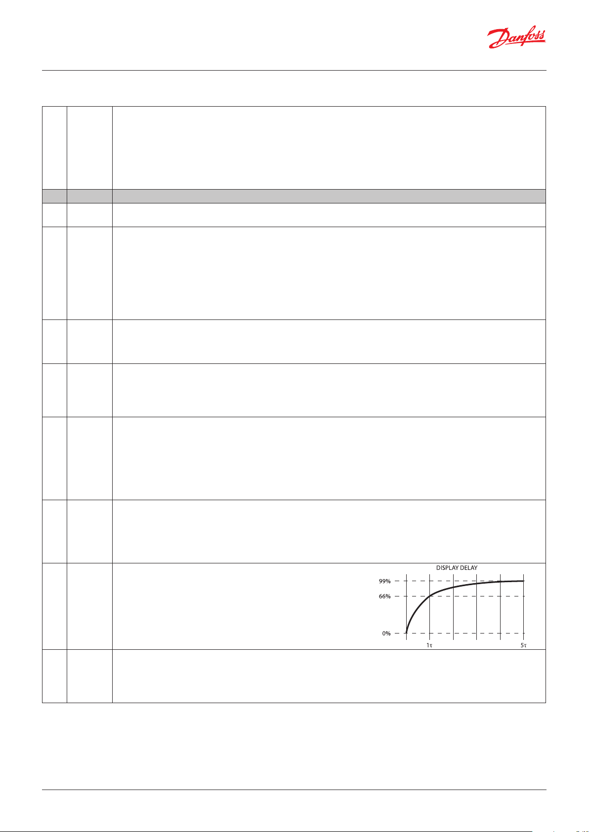
Display Delay
In order to provide a realistic temperature appearance for an application,
a display delay can be set.
The parameter sets the time constant τ (tau) of the moving average filter
for the display.
Physically, one time constant represents the time it takes the system’s
step-response to reach 66% of its final value and five time-constants
the time it takes to reach 99% of its final value.
"doF"
Min. -10.0 K
Max. 10.0 K
Default 0.0 K
Display Offset
This parameter is a relative value and allows the temperature displayed
to be different to the temperature measured.
For instance, at a measured temperature of 7°C and "doF" set to -2K, the
displayed temperature will be 5°C instead.
14 | BC227086437558en-000702 © Danfoss | DCS (vt) | 2019.07
Page 15
User Guide | ERC 111 Refrigeration Controller
"dLt"
Min. 0 min
Max. 60 min
Default 15 min
Lock Time After Defrost
In order not to show a rising temperature during defrosting, the displayed
temperature is locked at the temperature shown at the start of the defrost
cycle for the number of minutes set in this parameter.
"0": no lock.
"SSC"
Min. no
Max. yes
Default no
"SHo"
Min. no
Max. yes
Default no
"SdF"
Min. no
Max. yes
Default yes
"SCS"
Min. no
Max. yes
Default yes
"SdS"
Min. no
Max. yes
Default yes
"idp"
Min. 0
Max. 15
Default 15
Show Pull down state
If set to "yES", this parameter causes the display to show SC when the
system is in pull down mode.
If set to "nO", the temperature continues to be displayed.
Show Holiday
"no": display will show temperature or ECO mode during holiday mode.
"yES": display will show "HoL" during holiday mode.
Show Defrost
If set to "yES", this parameter causes the display to show DEF when the
system is in defrost mode. If set to "nO", the temperature continues to
be displayed.
Show compressor symbol
"no": compressor symbol will not show on display.
"yES": show compressor symbol on display.
Show Defrost symbol
"no": defrost symbol will not show on display.
"yES": show defrost symbol on display.
Info Menu Display Item
Switch of display items in Info menu. Visible on "KoolProg Software" O NLY.
Data structure:
0,0,0,0, (alarm item), (average item), (low temp), (high temp)".
ALA Alarm settings
"HAt"
Min. -100.0°C
Max. 200°C
Default 15.0°C
"LAt"
Min. -100.0°C
Max. 200°C
Default -50.0°C
"Htd"
Min. 0 min
Max. 240 min
Default 30 min
"Ltd"
Min. 0 min
Max. 240 min
Default 0 min
"Pdd"
Min. 0 min
Max. 960 min
Default 240 min
"uAL"
Min. no
Max. yes
Default no
"LEA"
Min. 0 hour
Max. 96 hour
Default 0 hour
High Temp Alarm
Absolute value.
By setting "HAt" to the maximum alarms will be deactivated.
Low Temp Alarm
Absolute value.
By setting "LAt" to the minimum value, alarms will be deactivated.
In most situations, the low alarm delay will be set to 0 to warn about
too low a temperature immediately.
Alarm delay on high temperature alarm
The number of minutes to wait before sounding an alarm once the
high temperature alarm temperature is reached.
Alarm delay on low temperature alarm
The number of minutes to wait before sounding an alarm once the
low temperature alarm temperature is reached.
Pull down delay
Normally, it is not necessary or desirable to sound an alarm during a pull
down (the initial phase of reaching the desired temperature). This
parameter prevents the high temperature alarm "HAt" sounding during pull down
and after a defrost for the number of minutes set for the parameter.
NOTE: it does not apply to the low temperature alarm "LAt".
Voltage alarm
"no": no voltage alarm.
"yES": voltage alarm activated.
Leakage alarm
Leakage detection for compressor protection.
"0": disable
© Danfoss | DCS (vt) | 2019.07 BC227086437558en-000702 | 15
Page 16

User Guide | ERC 111 Refrigeration Controller
"Abd"
Min. 0 min
Max. 999 min
Default 0 min
Alarm Buzzer Duration
The alarm sounds for 10 seconds, followed by silence for 50 seconds.
One alarm sequence therefore lasts 60 seconds. These values cannot be
changed. This parameter determines how long in minutes an audible
alarm will continue while there is still a reason to have an alarm.
If set to 999, the alarm will continue to sound until the reason for the
alarm is cleared – for example the temperature has dropped enough or
the door closed. In some cases, it may be necessary for a user or technician
to take action in order to clear the alarm. If set to 0, the alarm will never
sound.
"ACA"
Min. no
Max. yes
Default yes
Auto Clear of Alarm/Error/ACA
If this parameter is set to "nO":
The alarm status will not disappear automatically even if the condition
which caused the alarm is no longer valid or present.
If set to "yES":
As soon as the condition which caused the alarm is no longer valid or
present, the alarm status will automatically change back to inactive.
There will be no trace of the alarm having occurred.
In general, glass door merchandise applications will be set to "yES" and
commercial fridges and freezers set to "nO".
For example, if the temperature goes too high for a period there may
be food safety considerations in a freezer containing food but not in a
fridge with cold drinks.
ECS ECO strategy
"tto"
Min. 0 hour
Max. 168 hour
Default 0 hour
Time to pull down
Time which ERC stay in holiday mode to decide to enter pull
down or serving mode.
ECA ECO management
"Hto"
Min. -25.0 K
Max. 25.0 K
Default 6.0 K
Holiday Temperature Offset
Increase or decrease of temperature with respect to normal mode
during holiday mode.
ASi Assignments settings
"uSA"
Min. no
Max. yes
Default no
"t1A"
Min. -20.0 K
Max. 20.0 K
Default 0.0 K
"t2A"
MODBUS Safety
"on": MODBUS auto detection is enabled.
"yES": MODBUS communication is deactivaed.
Air Temperature Adjustment
(applies to non-Danfoss temperature sensors only)
This parameter is a relative value and allows adjustment of the control
sensor temperature.
For instance, at a measured temperature of 7*C and "tAd" set to -2 K,
the input from the control sensor will be 5*C instead.
Inputs and outputs are configurable
There are two steps:
1. Define the type of sensor attached to the input:
- temperature: light/digital.
2. Define the application for the sensor:
- temperature: control/condenser/evaporator.
- light: ECO/display/both.
- motion
- digital: door sensor.
Please contact your local Danfoss representative for information about
default settings.
NOTE: coded sensors will impact on the number of possible
configurations.
For instance: Danfoss supplies only 2-pole defrost sensors, so input "S3"
will most likely be used as a defrost/evaporator temperature sensor input.
16 | BC227086437558en-000702 © Danfoss | DCS (vt) | 2019.07
Page 17

23
User Guide | ERC 111 Refrigeration Controller
"S1C"
Default Stn
"S2C"
Default Stn
"S1A"
Default SCo
"S2A"
Default nC
"o1C"
Default CoP
"b1C"
Default noP
"b1L"
Default PoF
"b2C"
Default dEF
"b2L"
Default inF
"b3C"
Default tP
"b3L"
Default ECo
"b4C"
Default tn
"b4L"
Default Lig
"PS1"
Min. 0
Max. 999
Default 0
"PS2"
Min. 0
Max. 999
Default 0
"PS3"
Min. 0
Max. 999
Default 0
S1 Config/S1C
S2 Config/S2C
S3 Config/S3C
S4 Config/S4C
Available options are:
"Stn": for a standard temperature sensor NTC 5 K @ 25°C and TPE precision.
"Htn": for a high temperature sensor NTC 100 K @ 25°C.
S1 Application/S1A
S2 Application/S2A
S3 Application/S3A
S4 Application/S4A
Available options are:
"nC": not connected.
"SCo": temperature control.
"EuA": evaporator temperature.
"Con": condenser temperature (Condenser cleaning).
"AuS": only for showing temperature on display.
D01 Config
"CoP": direct compressor control.
"PiC": pilot Relay (no zero cross) – if using pilot relay to control a
compressor, this option must be used instead of "CoP".
"HEt": heating application, inverse output.
"PiH": pilot heat relay (no zero cross).
Lower left button:
Button 1 Config (short press)/b1C
Button 1 Config (long press)/b1L
Upper left button:
Button 2 Config (short press)/b2C
Button 2 Config (long press)/b2L
Upper right button:
Button 3 Config (short press)/b3C
The buttons can be programmed as follows:
Short press function Long press function
"noP": not operating
"tP": increase set point
"tn": decrease set point
"dEF": toggle defrost
"SuP": toggle super-cool/pull down
"diP" : increase display intensity
"din" : decrease display intensity
"CFA ": toggle °C and °F
Button 3 config (long press)/b3L
Lower right button:
Button 4 Config (short press)/b4C
Button 4 Config (long press)/b4L
NOTE: Your assignments may not be shown on the printed buttons. We advice to
use this functionality together with the fully integrated mounting model only.
Password level 1 / PS1
Password Level 2 / PS2
Password Level 3 / PS3
These assign passwords to the three levels of access. The password is a
three-digit number. Access levels are Shop, Service and OEM.
You may not therefore have access to change all the passwords.
Passwords are entered by using the up and down arrow buttons.
Danfoss advises against using passwords which are easy to remember
or enter, for example 111, 222, 123 etc.
NOTE: When accessing the controller with 3 wrong password in a sequence
ERC will automatically block access for 15 minutes.
"noP": not operating
"tP": increase set point
"tn": decrease set point
"dEF": toggle defrost
"SuP": toggle super-cool/pull down
"diP": increase display intensity
"din": decrease display intensity
"CFA ": toggle °C and °F
"PoF": ERC power ON/OFF
"HoL": enter holiday mode
"inF": enter info menu
1
4
© Danfoss | DCS (vt) | 2019.07 BC227086437558en-000702 | 17
Page 18

User Guide | ERC 111 Refrigeration Controller
Ser Service information settings
The parameters in the following section are READ ONLY and cannot be
changed by the user.
They provide information for technicians and OEM users.
NOTE: the only parameters that can be configured are: "oEL", " oEn", " oEH".
These parameters allow OEMs to enter their own product code.
"ACt" Accumulated Comp. run time
"AEt" Accumulated ERC up time
"uAC" Voltage value
Current main power supply voltage.
"ouS" DOs Status
Current relay open closed status.
"rL1" Relay 1 counter
Thousands of cycles of compressor relay since manufacture.
"int" Interval Counter
Compressor run time since last defrost.
"dnt" Defrost time counter
Duration of last defrost cycle [min].
"Snu" Serial number
Serial number given at manufacturing.
"Fir" SW version
Danfoss software version number.
"HAr" HW version
Danfoss hardware version number.
"onL" OrderNoLow
Danfoss order code number.
"onH" OrderNoHigh
Danfoss order code number.
"oEL" OEM code Low
"oEn" OEM code Middle
"oEH" OEM code High
"PAr " Parameter version
OEM parameter version number [requires EKA copy key update].
"CHd" Manufacturing date
Programme date WWY: week number and year number (2010-19).
"SFC" Set as Default
Resets all parameters to last good OEM settings.
"Ctt" Condenser Temp
Temperature of the condensor sensor.
"Et1" Evaporator1 Temp
Temperature of the evaporator sensor1.
"AuS" AUX Temp.
Temperature of the AUX sensor. invisible.
"att" Raw Sair Temp
18 | BC227086437558en-000702 © Danfoss | DCS (vt) | 2019.07
Page 19

User Guide | ERC 111 Refrigeration Controller
Display messages
"unP" Device is unprogrammed (relay output is lockt)
"Prg" Device has not finished programming (relay output is lockt)
"SC" Device is in pull-down mode (super-chill)
"dEF" Device is defrosting
Troubleshooting
Problem Probable cause Remedy
Compressor does not start Waiting for compressor delay timer
Defrost does not start Controller in pull down mode Defrost might be delayed during pull down
Alarm does not sound Alarm delayed Check ALA->Htd, Abd
Display alternates between condenser and
temperature
Display alternates between high and
temperature
Display alternates between low and
temperature
Display shows "dEf" Defrost in progress Check diS ->SdF
Defrost in progress
Line voltage to compressor too low
or too high
Condenser too hot Clean condenser
Temperature too high Check ALA->HAt
Temperature too low Check ALA -> LAt
Check CoP->CSt
Check CoP ->Pot /Pod
Check dEF ->dit, dot
Check CoP->uLi, uLo, uHi
Check parameter Pud->Pdi
Check Pud->Pdd
Check Con ->CAL, CbL
Alarm
code
"Hi" Air temperature is higher than
"Lo" Air temperature is lower than
"Con" Condenser temperature is too
"uHi" Line voltage is higher than
"uLi" Line voltage is lower than
"LEA" Compressor continuous
"E01" "S1" error Always Blink "E01". If configured: cut in alarm relay, beep the buzzer "S1" sensor failure
"E02" "S2" error Always Blink "E02". If configured: cut in alarm relay, beep the buzzer "S2" sensor failure
Trigg er Automatic
clearance
User configured Blink "Hi" with the highest temperature; If configured:
"AL A->H at " for "AL A->H td "
User configured Blink "Lo" with the lowest temperature. If configured:
"LAt" for "Ltd"
User configured Blink "Con". If configured: cut in alarm relay, beep the buzzer Condenser alarm
high or too low
Always Blink "uHi". If configured: cut in alarm relay, beep the buzzer High voltage alarm
"Cop->uHi"
Always Blink "uLo". If configured: cut in alarm relay, beep the buzzer. Low voltage alarm
"Cop->uLi"
Always Blink "LEA". If configured: cut in alarm relay, beep the buzzer Leakage alarm
running for more than
"AL A->L EA "
Outputs Comments
High temperature alarm
cut in alarm relay, beep the buzzer
Low temperature alarm
cut in alarm relay, beep the buzzer
(short or open)
(short or open)
© Danfoss | DCS (vt) | 2019.07 BC227086437558en-000702 | 19
Page 20

User Guide | ERC 111 Refrigeration Controller
Typical applications
Glass Door Merchandiser, No-frost freezer/sub-zero cooler
ERC 111
ERC 111, Red LED, without buzzer 080G3230
ERC 111, Blue LED, without buzzer 080G3231
Temperature Sensor for Cabinet
Temperature Control
PVC Standard Connector type
3-pole
470 mm 077F8751 1000 mm 077F8786
1000 mm 077F8757 1500 mm 077F8790
1500 mm 077F8761 2000 mm 077F8794
2000 mm 077F8765 3000 mm 077F8798
2200 mm 077F8767 6000 mm 077F2029
3000 mm 077F8769
3500 mm 077F8723
6000 mm 077F2019
Temperature Sensor for
Condenser Temperature Control
PVC Standard Connector type
2-pole
20 | BC227086437558en-000702 © Danfoss | DCS (vt) | 2019.07
Page 21

User Guide | ERC 111 Refrigeration Controller
Sensor placement
Control sensor
Control sensor
The control sensor must always be connected and is
used for controlling the cut-in and cut-out of the
compressor according to the set point.
The sensor is also used for the displayed temperature.
Vertical coolers with fan
Most common placement is in the return air to the
evaporator. The sensor can be placed close to the
fan – even when the fan is pulsed during compressor
OFF periods: the updating of the temperature is
blocked when the fan is stopped and only updated
when the fan has been running for a while, so that the
heat from the fan does not affect the temperature
reading.
For applications sensitive to sub-zero temperatures,
sensor placement in the evaporator outlet air can be
considered.
Vertical freezers with fan
Placement in the return air or in the freezer
compartment.
Coolers without fan
The best results are normally obtained when the
sensor is placed at the side-wall, 10 cm from the back
and approximately at 1/3 from the bottom or where
the evaporator ends.
The control sensor must always be connected and is
used for controlling the cut-in and cut-out of the
compressor according to the set point.
The sensor is also used for the displayed temperature.
Condenser sensor
The condenser sensor is used to protect the compressor
against high pressure when the condenser is blocked or
the condenser fan fails.
Placement of sensor
Place the sensor at the liquid side of the condenser.
Use a metal bracket or metal tape to ensure good
thermal conductivity. Be sure that the cable does not
pass hot spots at the compressor or condenser that
exceeds 80°C.
© Danfoss | DCS (vt) | 2019.07 BC227086437558en-000702 | 21
Page 22

User Guide | ERC 111 Refrigeration Controller
Application Matrix
ERC 111 Output Input
Application Type DO1 S1 S2 Di
Standard beverage cooler ERC 111 Comp Control Defrost or condenser -
Out-door beverage cooler ERC 111 Comp Control Defrost or condenser -
CFF refrigerator ERC 111 Comp Control Defrost or condenser -
CFF freezer static evaporator ERC 111 Comp Control Condenser -
NOTE:
• Select only one function per input, e.g. defrost or condenser sensor.
• Make sure that the accessory you select has a matching connector to the input, e.g. a sensor for input "S2" must have "S2" connector.
• Condenser sensor are optional and can be omitted.
22 | BC227086437558en-000702 © Danfoss | DCS (vt) | 2019.07
Page 23

User Guide | ERC 111 Refrigeration Controller
© Danfoss | DCS (vt) | 2019.07 BC227086437558en-000702 | 23
Page 24

© Danfoss | DCS (vt) | 2019.07 BC227086437558en-000702 | 24
ADAP-KOOL®
 Loading...