

Page 1
www.danfoss.com/erc
This reference manual is intended to be used primarily by OEMs for the purposes of programming ERC 102.
It may also be useful for technicians. It is not intended as a user guide for end users.
ERC 102 refrigeration controller
Reference manual
MAKING MODERN LIVING POSSIBLE
Page 2

2
Table of Content
1. INTRODUCTION . . . . . . . . . . . . . . . . . . . . . . . . . . . . . . . . . . . . . . . . . . . . . . . . . . . . . . . . . . 4
2. CONTENT OF THE BOX
2.1 Main product . . . . . . . . . . . . . . . . . . . . . . . . . . . . . . . . . . . . . . . . . . . . . . . . . . . . . . . . 5
2.2 Accessories . . . . . . . . . . . . . . . . . . . . . . . . . . . . . . . . . . . . . . . . . . . . . . . . . . . . . . . . . 5
2.3 Connections . . . . . . . . . . . . . . . . . . . . . . . . . . . . . . . . . . . . . . . . . . . . . . . . . . . . . . . . 7
3. OVERVIEW OF THE PRODUCT
3.1 Control buttons . . . . . . . . . . . . . . . . . . . . . . . . . . . . . . . . . . . . . . . . . . . . . . . . . . . . . . 8
3.2 Connector inputs . . . . . . . . . . . . . . . . . . . . . . . . . . . . . . . . . . . . . . . . . . . . . . . . . . . . . 8
3.3 Connector outputs . . . . . . . . . . . . . . . . . . . . . . . . . . . . . . . . . . . . . . . . . . . . . . . . . . . . 9
3.4 Top label . . . . . . . . . . . . . . . . . . . . . . . . . . . . . . . . . . . . . . . . . . . . . . . . . . . . . . . . . . . 9
4. MOUNTING
4.1 Rear mounting – Option 1 . . . . . . . . . . . . . . . . . . . . . . . . . . . . . . . . . . . . . . . . . . . . . . . 10
4.1.1 Unmounting . . . . . . . . . . . . . . . . . . . . . . . . . . . . . . . . . . . . . . . . . . . . . . . . . . . . . . . 11
4.2 Front mounting – Option 2 . . . . . . . . . . . . . . . . . . . . . . . . . . . . . . . . . . . . . . . . . . . . . . 12
4.2.1 Unmounting . . . . . . . . . . . . . . . . . . . . . . . . . . . . . . . . . . . . . . . . . . . . . . . . . . . . . . . 13
4.3 Fully-integrated design. . . . . . . . . . . . . . . . . . . . . . . . . . . . . . . . . . . . . . . . . . . . . . . . . 13
5. CONTROLLING/NAVIGATION
5.1 KoolProg and Gateway . . . . . . . . . . . . . . . . . . . . . . . . . . . . . . . . . . . . . . . . . . . . . . . . . 14
5.2 Docking station . . . . . . . . . . . . . . . . . . . . . . . . . . . . . . . . . . . . . . . . . . . . . . . . . . . . . 14
5.3 Manual operation with buttons (Direct Access) . . . . . . . . . . . . . . . . . . . . . . . . . . . . . . . . . 14
5.3.1 ERC Front and Button Functionallity . . . . . . . . . . . . . . . . . . . . . . . . . . . . . . . . . . . . . . . . 14
5.3.2 Direct functions for access. . . . . . . . . . . . . . . . . . . . . . . . . . . . . . . . . . . . . . . . . . . . . . . 15
5.3.3 Operating the menu . . . . . . . . . . . . . . . . . . . . . . . . . . . . . . . . . . . . . . . . . . . . . . . . . . 16
5.3.4 Menu structure . . . . . . . . . . . . . . . . . . . . . . . . . . . . . . . . . . . . . . . . . . . . . . . . . . . . . . 18
5.3.5 Password protection . . . . . . . . . . . . . . . . . . . . . . . . . . . . . . . . . . . . . . . . . . . . . . . . . . 18
6. CONFIGURATION OF INPUTS AND OUTPUTS
6.1 Changing input and output configuration settings . . . . . . . . . . . . . . . . . . . . . . . . . . . . . . . 19
6.2 Program the buttons . . . . . . . . . . . . . . . . . . . . . . . . . . . . . . . . . . . . . . . . . . . . . . . . . . 22
6.3 Set passwords . . . . . . . . . . . . . . . . . . . . . . . . . . . . . . . . . . . . . . . . . . . . . . . . . . . . . . 23
6.4 Set lighting function . . . . . . . . . . . . . . . . . . . . . . . . . . . . . . . . . . . . . . . . . . . . . . . . . . 23
ERC 102 Reference manual
Page 3

3
7. PARAMETERS
7.1 Thermostat . . . . . . . . . . . . . . . . . . . . . . . . . . . . . . . . . . . . . . . . . . . . . . . . . . . . . . . . 24
7.2 Alarms . . . . . . . . . . . . . . . . . . . . . . . . . . . . . . . . . . . . . . . . . . . . . . . . . . . . . . . . . . . 26
7.3 Compressor . . . . . . . . . . . . . . . . . . . . . . . . . . . . . . . . . . . . . . . . . . . . . . . . . . . . . . . . 28
7.4 Defrost . . . . . . . . . . . . . . . . . . . . . . . . . . . . . . . . . . . . . . . . . . . . . . . . . . . . . . . . . . . 31
7.5 Fan. . . . . . . . . . . . . . . . . . . . . . . . . . . . . . . . . . . . . . . . . . . . . . . . . . . . . . . . . . . . . . 35
7.6 Energy management . . . . . . . . . . . . . . . . . . . . . . . . . . . . . . . . . . . . . . . . . . . . . . . . . . 35
7.7 Pull down . . . . . . . . . . . . . . . . . . . . . . . . . . . . . . . . . . . . . . . . . . . . . . . . . . . . . . . . . 37
7.8 Automatic heater control . . . . . . . . . . . . . . . . . . . . . . . . . . . . . . . . . . . . . . . . . . . . . . . 38
7.9 Condenser protection . . . . . . . . . . . . . . . . . . . . . . . . . . . . . . . . . . . . . . . . . . . . . . . . . 39
7.10 Display . . . . . . . . . . . . . . . . . . . . . . . . . . . . . . . . . . . . . . . . . . . . . . . . . . . . . . . . . . . 40
7.11 Assignments . . . . . . . . . . . . . . . . . . . . . . . . . . . . . . . . . . . . . . . . . . . . . . . . . . . . . . . 42
7.12 Service . . . . . . . . . . . . . . . . . . . . . . . . . . . . . . . . . . . . . . . . . . . . . . . . . . . . . . . . . . . 43
8. TECHNICAL SPECS . . . . . . . . . . . . . . . . . . . . . . . . . . . . . . . . . . . . . . . . . . . . . . . . . . . . . . . 44
APPENDIX
I Parameter quick list . . . . . . . . . . . . . . . . . . . . . . . . . . . . . . . . . . . . . . . . . . . . . . . . . . . 45
II Code numbers and lenghts . . . . . . . . . . . . . . . . . . . . . . . . . . . . . . . . . . . . . . . . . . . . . . 51
III Troubleshooting . . . . . . . . . . . . . . . . . . . . . . . . . . . . . . . . . . . . . . . . . . . . . . . . . . . . . 52
IV Typical applications – wiring diagrams . . . . . . . . . . . . . . . . . . . . . . . . . . . . . . . . . . . . . . . 53
IV.1 Typical Wiring Diagram, ERC 102D, Glass Door Merchandiser,
No-frost freezer / sub-zero cooler . . . . . . . . . . . . . . . . . . . . . . . . . . . . . . . . . . . . . . 53
IV.2 Typical Wiring Diagram, ERC 102C, Glass Door Merchandiser . . . . . . . . . . . . . . . . . . . . . 54
IV.3 Typical Wiring Diagram, ERC 102D, Gastro No-frost freezer . . . . . . . . . . . . . . . . . . . . . . 55
IV.4 Typical Wiring Diagram, ERC 102C, Gastro Cooler. . . . . . . . . . . . . . . . . . . . . . . . . . . . . 56
V Application specificatons . . . . . . . . . . . . . . . . . . . . . . . . . . . . . . . . . . . . . . . . . . . . . . . 57
V.1 Control sensor. . . . . . . . . . . . . . . . . . . . . . . . . . . . . . . . . . . . . . . . . . . . . . . . . . . 57
V.2 Evaporator sensor . . . . . . . . . . . . . . . . . . . . . . . . . . . . . . . . . . . . . . . . . . . . . . . . 58
V.3 Condenser sensor . . . . . . . . . . . . . . . . . . . . . . . . . . . . . . . . . . . . . . . . . . . . . . . . 58
V.4 Ambient light sensor. . . . . . . . . . . . . . . . . . . . . . . . . . . . . . . . . . . . . . . . . . . . . . . 59
V.5 Door sensor . . . . . . . . . . . . . . . . . . . . . . . . . . . . . . . . . . . . . . . . . . . . . . . . . . . . 59
ERC102 Application Matrix . . . . . . . . . . . . . . . . . . . . . . . . . . . . . . . . . . . . . . . . . . . . . . 60
ERC 102 Reference manual
Page 4

4
1. INTRODUCTION
The ERC 102 is an electronic refrigeration controller with an LED display especially developed for bottle
coolers and commercial fridges and freezers. It is particularly suited for OEM customers where time, easy and
reliable installation and high quality need to go hand in hand with flexibility.
The latest generation CPU, plenty of memory and high-end electronic components allow for a uniquely
versatile software. Three separate password-protected user levels can be used to control more than 200
different parameters to fit all individual requirements.
ERC 102’s IP rated body, advanced materials and internationally approved hardware design open it up for use
in almost any climate globally, indoors as well as outdoors.
Laboratory work with ERC 102 is rendered easy and flexible. Danfoss KoolProg software with a USB-powered
gateway accelerate programming; on the OEM assembly line, just one Danfoss unique Docking station can
easily program up to 3,000 controllers a day – at zero inventory cost.
It uses a globally-compatible, lightweight, switch mode power supply.
All components have been carefully selected to help reduce the CO2 footprint. The globally-compatible
internal power supply uses an average of just 0.7W – 4 times less than an average controller today.
Sensors include ambient light for display brightness, which also detect shop opening hours for
energy-saving routines. Door and temperature sensors provide input for controlling the compressor,
the light, the fan and automatic defrosting.
ERC 102 Reference manual
Page 5
5
2. CONTENT OF THE BOX
2. 1 Main product
2.2 Accessories
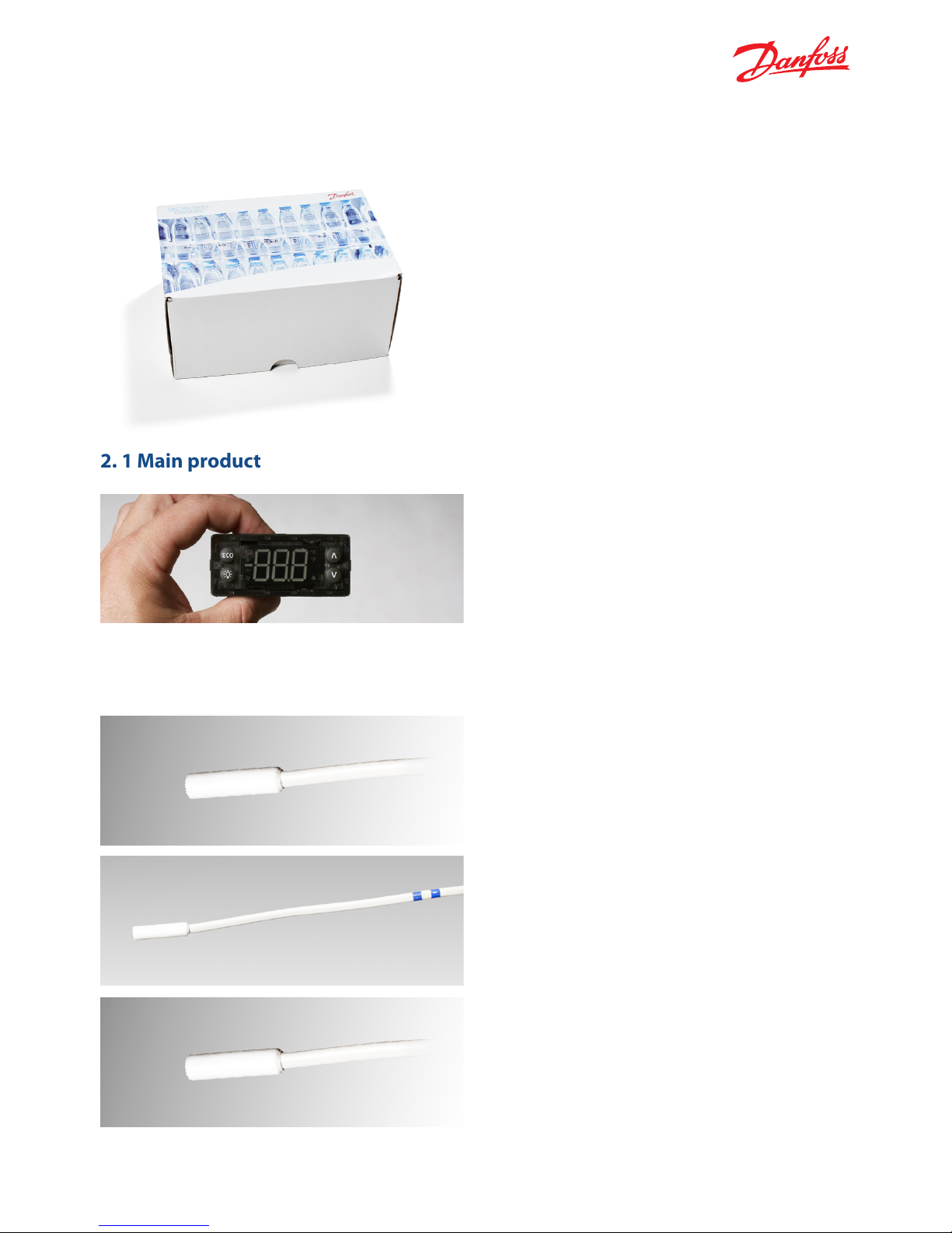
ERC 102 control unit without front frame.
NOTE: The front frame is included in the sample box.
If delivered in a sample box the following content
is shipped. The sample box is not available for other
than sample purposes.
See Appendix II for code numbers and lengths.
For box lots (pcs per box), please contact your local
Danfoss representative.
Control temperature sensor: see Appendix II for
different lengths and connector types.
Condenser temperature sensor: should be
mounted on the condenser. For detailed
mounting instructions, please contact your
local Danfoss representative.
NOTE: This sensor is not included in the sample box .
Defrost sensors can also be used as condenser
sensors.
Defrost temperature sensor: should be mounted on
the evaporator. For detailed mounting instructions,
please contact your local Danfoss representative.
NOTE: Defrost sensors can also be used as condenser
sensors.
ERC 102 Reference manual – 2 CONTENT OF THE BOX
Page 6
6
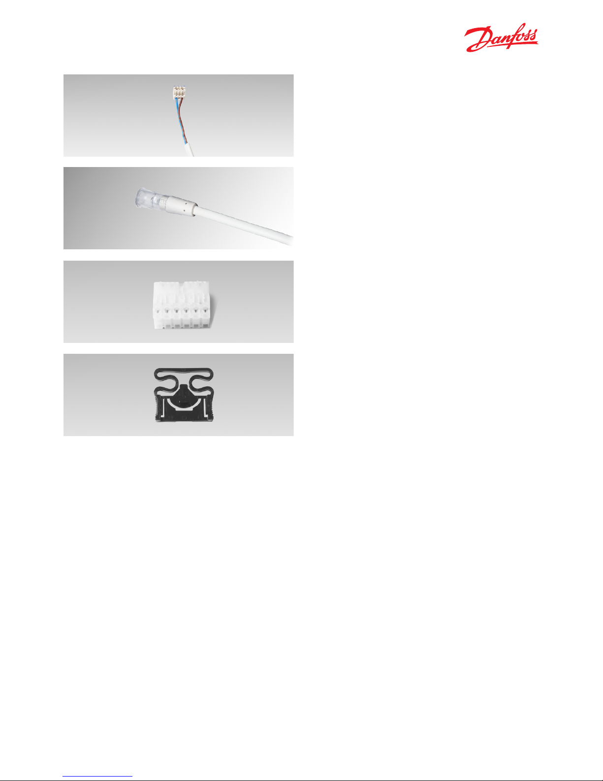
Door sensor connector cable: please see Appendix II
for lengths and code numbers.
NOTE: Door sensor: is optional and is a connector
and cable with spade terminals compatible with door
contacts used in refrigeration applications.
Clips: are used to secure the ERC 102 in place in
the case of rear mounting. They are not used with
front mounting. There are two identical clips, one
placed on either side of the ERC 102. See Chapter 4
– Mounting – for further details.
Light sensor: is optional and is used to measure the
level of ambient light around the cabinet so
that night and day (Economy / Normal) modes
of operation can automatically be set, as well
as the brightness of the display.
Power plug: for laboratory use, low quantity
OEM production or whenever spade connectors are
not available.
ERC 102 Reference manual – 2 CONTENT OF THE BOX
Page 7
7
2.3 Connections
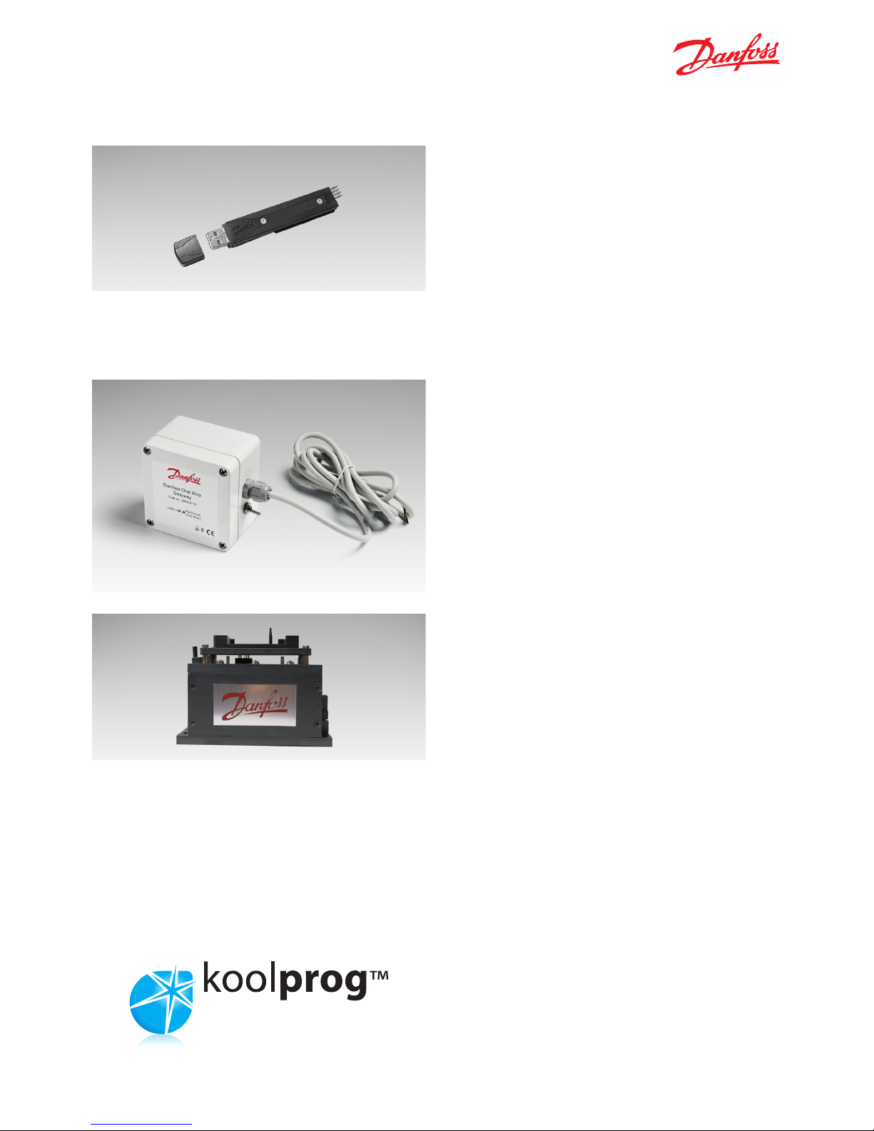
Programming an individual unit in a laboratory:
the USB gateway requires KoolProg Software
running on a PC. It enables parameters to be set in
real time and an array of status information to be
read (bidirectional connection). This method is used
to determine the correct parameters during R&D.
Once the desired settings have been determined,
a KoolProg ERC specific parameter file is saved to the
EKA183 USB copy key for later mass programming.
The USB Gateway is a laboratory tool, offering fast
and easy programming of any ERC102 controller.
KoolProg software installation is provided;
the gateway is standard inventory for OEM labs.
Mass programming on an assembly line:
the docking station is used for high volume
programming of ERC controllers, for example
on an assembly line. The docking station is a
write-only device.
See above (Programming an individual unit) for
preparing the EKA183 USB copy key, which is to
be inserted into the docking station. The settings
are then loaded into each successive controller
in a matter of seconds.
KoolProg software is not required for mass
programming.
Note: please refer to the koolprog manual for more
details about programming.
KoolProg: is the software from Danfoss for
programming the ERC 102 via a USB cable and
a PC rather than with the front panel buttons.
Please refer to the KoolProg manual for details.
ERC 102 Reference manual – 2 CONTENT OF THE BOX
Page 8
8
The ERC 102 is a state-of-the art, IP65 (front)-rated
refrigeration controller for use in both Glass Door
Merchandising and Commercial Fridges and Freezer
applications.
With four inputs and four outputs, powerful
algorithms and input from multiple sensors, the ERC
102 delivers both energy-saving routines and
compressor, light, fan and defrost control.
Together with the Danfoss docking station,
programming of pre-prepared parameter sets can
be achieved in just five seconds. There are over 200
parameters (see Chapter 7) including innovative
features such as night mode detection,
store opening detection, door open alarm control
and display dimming for restaurants.
The ERC 102 can also be programmed via USB using
the Danfoss KoolProg software, allowing the most
suitable parameter findings to be found quickly
during the application development process.
It is also possible to operate and program the
controller using the control buttons (only when
actually installed in a refrigerator / freezer).
Overview of ERC 102 models:
Model: Digital outputs:
ERC 102A 1 relay
ERC 102C 3 relays
ERC 102D 4 relays
3. OVERVIEW OF THE PRODUCT
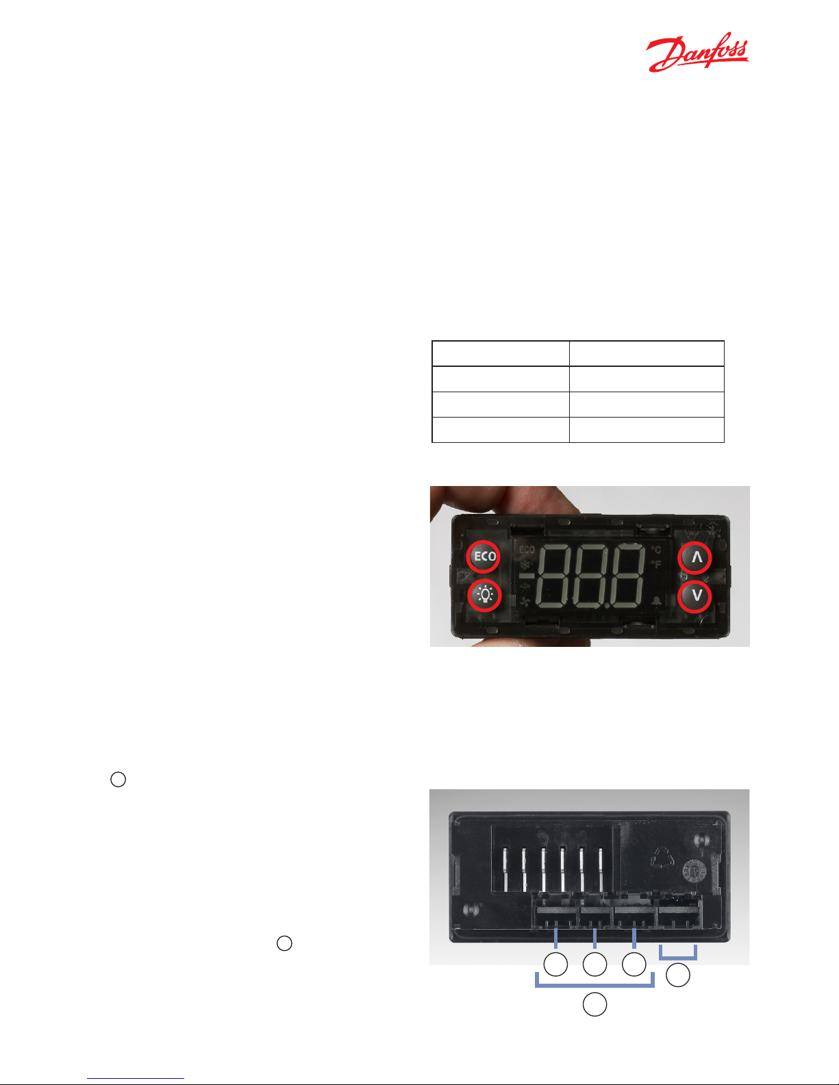
3.2 Connector inputs
Connect up to four Danfoss original sensors according
to your application needs.
There are three analogue inputs: S1, S2 and
S3 (a).
Supported input options:
· Ambient light - analogue data [luminens]
· Cabinet (air) temperature - analogue data [°C]
· Evaporator temperature - analogue data [°C]
· Condenser temperature - analogue data [°C]
· Digital input - binary data [on/off]
There is one digital input: diC (b) for PC
communication being used either with a door
sensor or with the USB Gateway.
NOTE: for detailed information refer to section 6.1.
The ambient light sensor can be used for determining shop open / closed times for economy mode
switching, for determining the brightness of the LED
display or both.
3.1 Control buttons
The ERC 102 has four buttons (circled in image)
on the front which can be programmed to perform
different functions. See Chapter 6 – Configuration of
inputs and outputs for detailed information.
ERC 102 Reference manual – 3 OVERVIEW OF THE PRODUCT
b
a
S1 S2 S3
Page 9
9
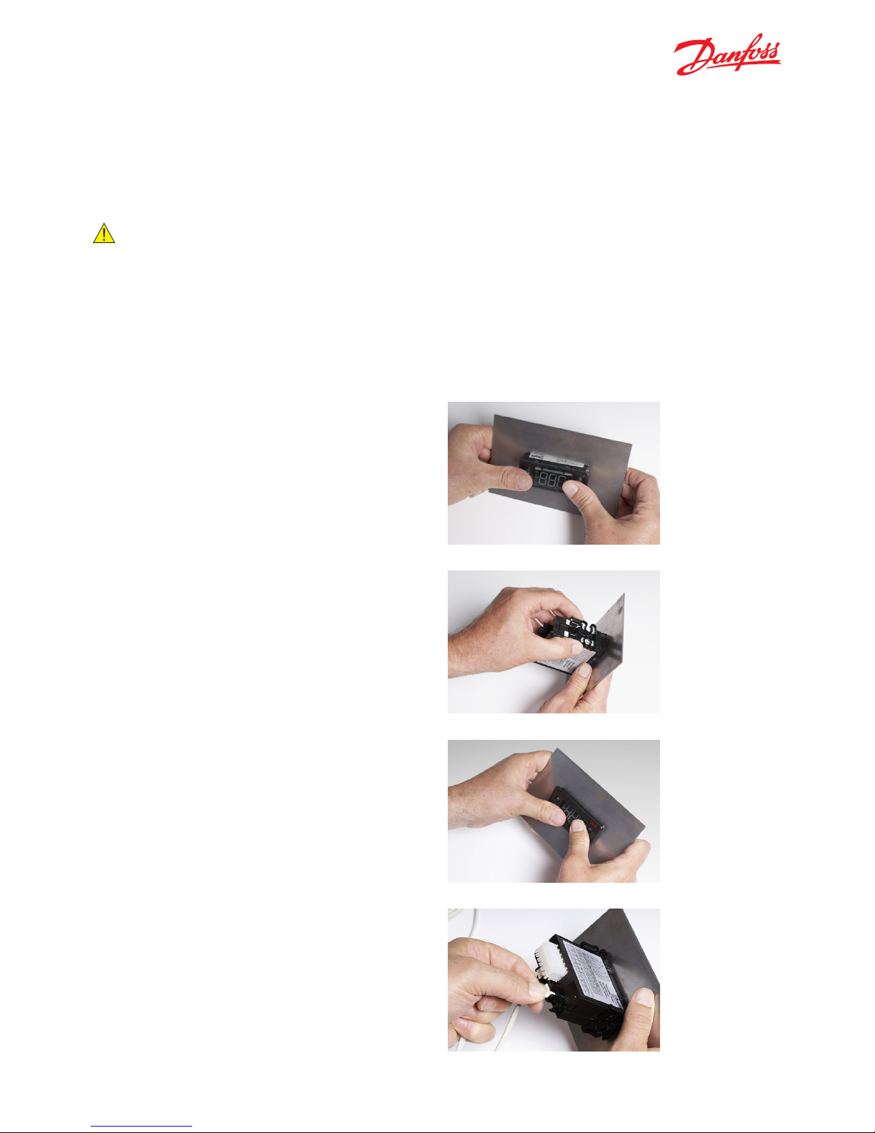
3.4 Top label
The illustration shows an example of a top label
affixed to an ERC 102D. The examples show what
is connected:
• Output 1 is used to switch the compressor
on and off.
• Outputs 2 and 3 are power – Live and Neutral.
• Output 4 is used to switch the heater on and off.
• Output 5 is used to switch the fan on and off.
• Output 6 is used to switch the light on and off.
• Input D (S1) is connected to a Cabinet Sensor to
measure temperature inside the cabinet.
• Input C(di) is used for Communications – a docking
station or KoolProg software running on a PC.
• Input B(S2) is connected to an Evaporator
Temperature Sensor.
• Input A(S3) is connected to an Ambient Light Sensor.
NOTE: Parameters depend on the code number sup-
plied. Please refer to the code number
specific technical drawing or use the KoolProg information menu. For other applications,
a condenser sensor and a door sensor may
be used.
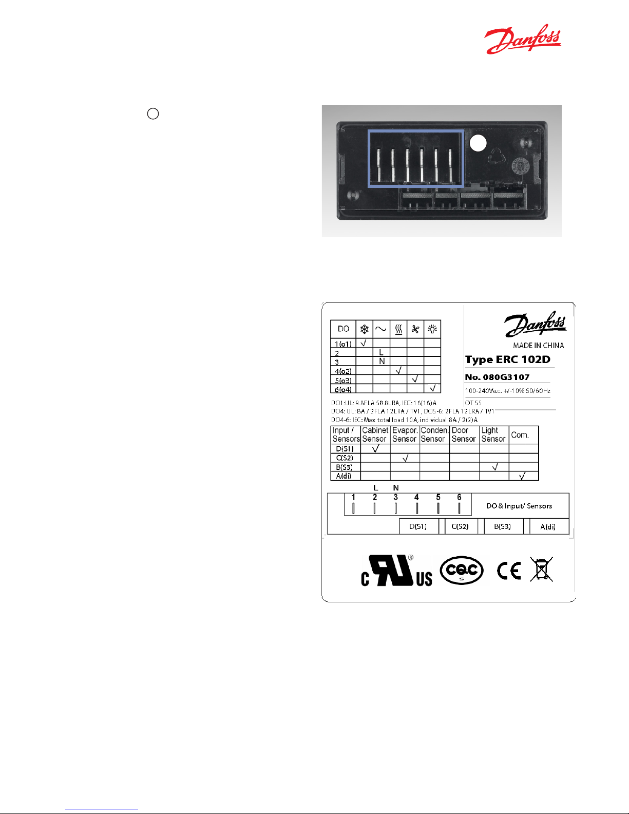
3.3 Connector outputs
All four outputs (c) are digitally controlled
on/off relays.
Functions controlled are:
• Compressor
• Pilot Relay
• Heater
• Defrost heater / valve for hot gas
• Alarm
• Fan
• Light
ERC 102 Reference manual – 3 OVERVIEW OF THE PRODUCT
C
Page 10
10
There are three options for mounting the ERC 102
in a freezer or refrigerator.
SAFETY INFO
Risk of electrocution!
For mounting: Do not connect mains power until
the controller is correctly mounted.
For unmounting: Disconnect the power supply
before unmounting.
4. MOUNTING
1. Insert the ERC 102 into the cabinet.
2. Attach the clips to each side of the ERC 102.
3. Place the front frame on to the ERC 102 and click
it into place.
4. Connect the sensors and outputs as required and
then the power cable (see Chapter 6 – parameters
for information about programming which inputs
and outputs are applicable to your configuration).
4.1 Rear mounting – Option 1
ERC 102 Reference manual – 4 MOUNTING
Page 11
11
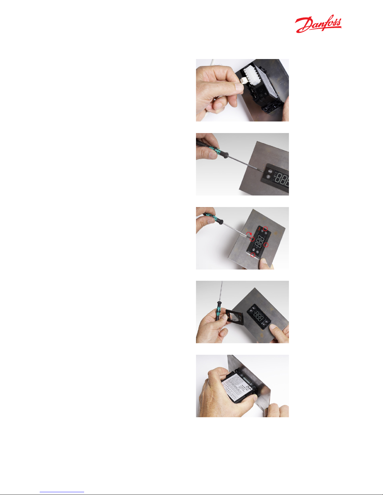
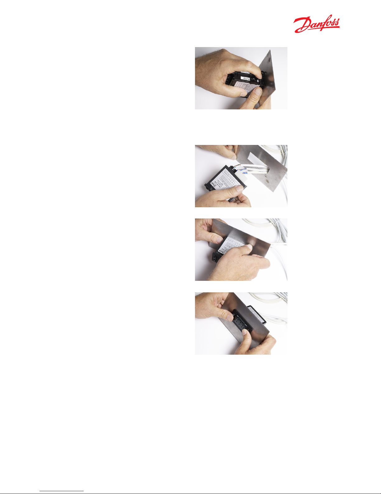
4.1.1 Unmounting
1. Disconnect the power cable and then the sensors.
2. Use a flat head screwdriver (ideally the one
supplied with the ERC 102 sample package)
and insert it carefully between the front frame
and the controller.
3. Gently twist the screwdriver to remove the
front frame. Do this in four places next to each
clip area.
5. Reach around the side to the clips.
ERC 102 Reference manual – 4 MOUNTING
Page 12
12
6. Press the centre section of each clip to release
them in turn. Push the controller carefully out
of the cabinet.
1. Connect all the cables as required (see Chapter 6
– parameters for information about programming
which inputs and outputs are applicable to your
configuration).
2. Insert the ERC 102 into place in the cabinet.
3. Press the front frame into place – this locks the
ERC 102 into position.
NOTE: there is no need to use the clips for
front mounting.
4.2 Front mounting – Option 2
ERC 102 Reference manual – 4 MOUNTING
Page 13
13
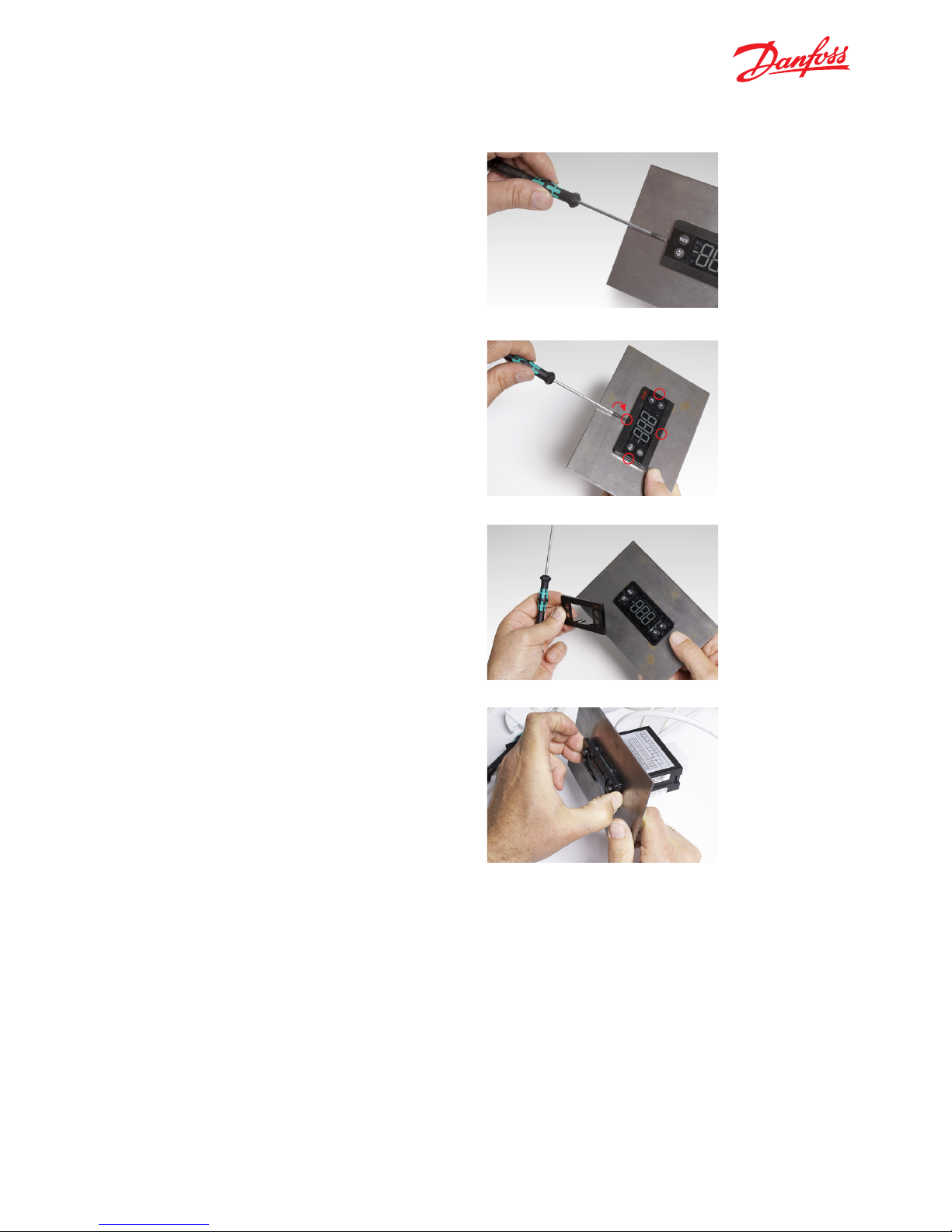
1. Use a flat head screwdriver (ideally the
one supplied with the ERC 102 sample package)
and insert it carefully between the front frame
and the controller.
3. Cabinet. Do not use a different type of
screwdriver or a sharp item such as a knife
which risks causing damage.
4.2.1 Unmounting
4.3 Fully integrated design – Option 3
An option is available for OEMs wanting to use the ERC
102 in a fully-integrated design. Please contact your
local Danfoss representative for more information.
2. Gently twist the screwdriver to remove the
front frame. Do this in four places next to each
clip area.
ERC 102 Reference manual – 4 MOUNTING
Page 14

14
The ERC 102 can be controlled in three ways:
using KoolProg software, the Danfoss Docking
Station or manually by means of the buttons
on the front panel.
5.1 KoolProg/Gateway
KoolProg is licenced Danfoss software offering easy
parameter setup via a USB gateway. This software
is supplied separately; for technical literature and
further information, please contact your local
Danfoss representative.
5.2 Docking station
The ERC 102 controller docking station is supplied
separately. For further information, please contact
your local Danfoss representative.
5.3 Manual operation with buttons
(Direct Access)
Explained as follows:
5.3.1 ERC Front and Button Functionallity
5. CONTROLLING / NAVIGATION AND ACCESS LEVELS
1 Press: Variable direct function, e.g.ECO/Night mode
Sub function: Back
1 Press: Variable direct function, e.g. light
Sub function: OK
1 Press: Temperature setpoint
Sub function: Up
1 Press: Temperature setpoint
Sub function: Down
Sub function: Up
1 Click: Temperature setpoint
ERC 102 Reference manual – 5 CONTROLLING / NAVIGATION AND ACCESS LEVELS
Page 15
15
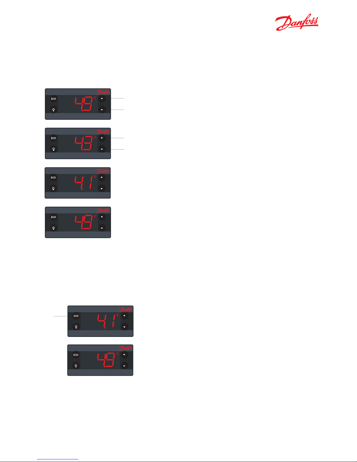
5.3.2 Direct functions for access
Changing the Desired Temperature Setpoint (applies similarly when using Fahrenheit scale):
After 3 0 seconds, the display aut omatically
reverts to showing the current temperature
The display shows the current
temperature.
(Current temperature)
(Flashing: temperature setpoint)
(Flashing: temperature setpoint)
Press: up/down to adjust setpoint
1.)
2.)
3.)
4.)
Turning On/Off the ECO Function:
1.)
2.)
Press briefly
to enter
ECO mode
The gree n ECO symbol
is lit when in ECO mode
Sub function: Up
1 Click: Temperature setpoint
Sub function: Up
1 Click: Temperature setpoint
Sub function: Up
1 Click: Temperature setpoint
ECO
˚C
ERC 102 Reference manual – 5 CONTROLLING / NAVIGATION AND ACCESS LEVELS
Sub function: Up
1 Click: Temperature setpoint
Sub function: Up
1 Click: Temperature setpoint
Sub function: Up
1 Click: Temperature setpoint
Page 16
16
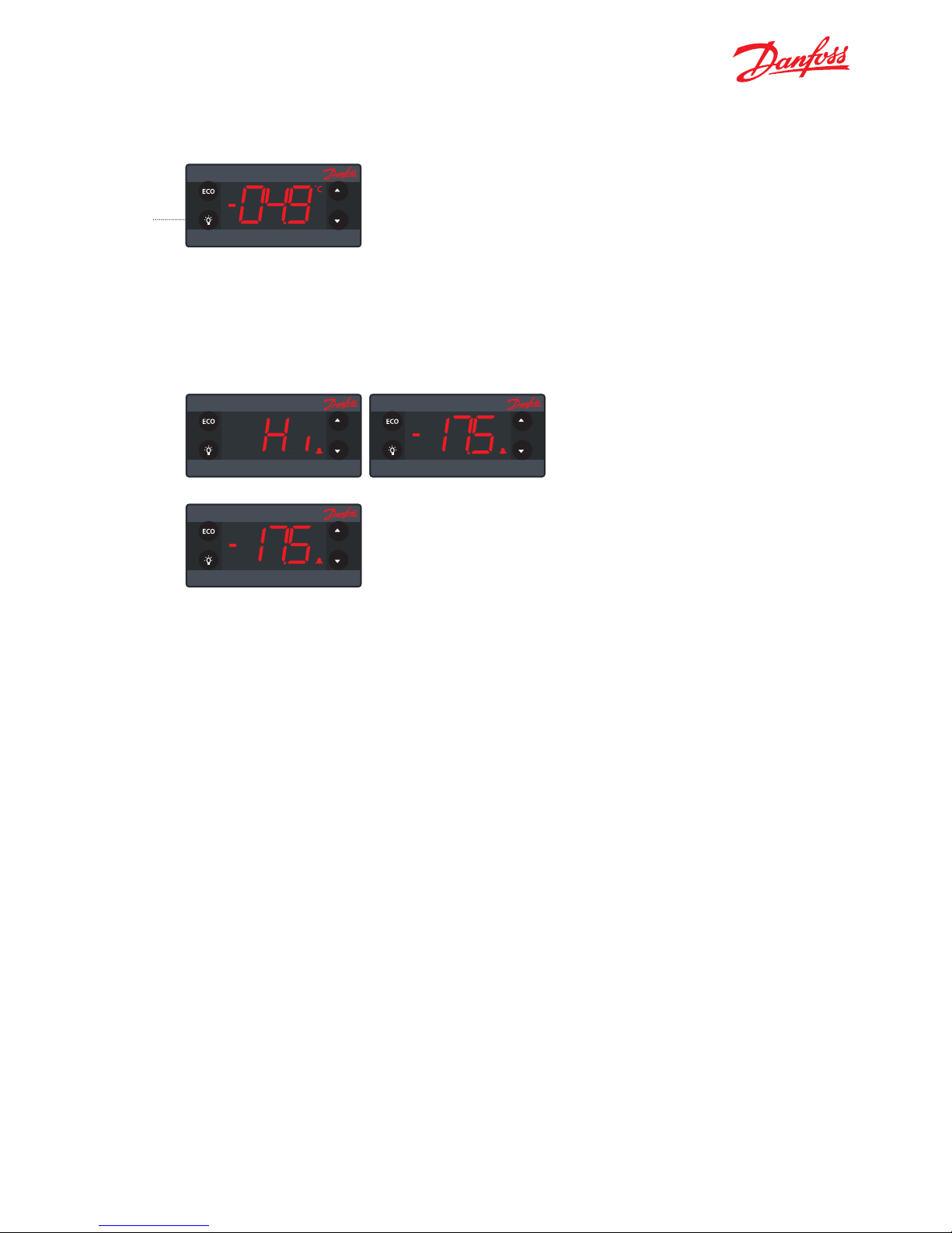
Turn ON/Off the Light
Acknowledging Alarms:
5.3.3 Operating the menu
Button assignments in this manual refer
to the Glass Door Merchandiser default ERC 102.
For customised controls you may assign different
shortcuts (ASI menu --> button configuration).
Use this feature only when the ERC 102 is supplied
without button prints.
INFO: Some parameters may be hidden to you.
When scrolling through menus, the parameters
available will have been pre-determined using
KoolProg software. Your access level will determine
which parameters you can view and edit.
To turn off the Light
Press the light button again
Press any button to acknowlege
Flashing
Press the
Light button
briefly
1.)
1.)
2.)
Sub function: Up
1 Click: Temperature setpoint
Sub function: Up
1 Click: Temperature setpoint
Sub function: Up
1 Click: Temperature setpoint
Sub function: Up
1 Click: Temperature setpoint
ERC 102 Reference manual – 5 CONTROLLING / NAVIGATION AND ACCESS LEVELS
Page 17
17
Sub function: Up
1 Click: Temperature setpoint
Sub function: Up
1 Click: Temperature setpoint
Sub function: Up
1 Click: Temperature setpoint
Sub function: Up
1 Click: Temperature setpoint
Sub function: Up
1 Click: Temperature setpoint
Sub function: Up
1 Click: Temperature setpoint
Sub function: Up
1 Click: Temperature setpoint
Sub function: Up
1 Click: Temperature setpoint
Sub function: Up
1 Click: Temperature setpoint
1.)
2.)
4.)
3.)
5.)
6.)
7.)
8.)
9.)
To select: press the lower left button (OK)
To confirm: press the lower left button (OK)
Press: OK to accept
and return to parameter name
Press: u pper left bu tton (back)
to return to parameter group
Press: u pper left bu tton (back)
to return to the menu
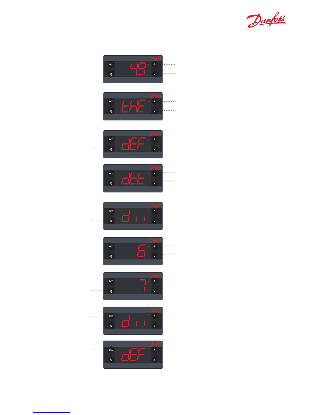
Example of Changing a Parameter:
Press and hold for 5 seconds to enter the menu
Press: up/down to scroll
through the menu
Press: up/down to find
the desired parameter
Press: up/down to enter
the desired value
(scroll through parameter groups)
(scroll through group “dEf” parameters)
ERC 102 Reference manual – 5 CONTROLLING / NAVIGATION AND ACCESS LEVELS
Page 18
18
Sub function: Up
1 Click: Temperature setpoint
Sub function: Up
1 Click: Temperature setpoint
Sub function: Up
1 Click: Temperature setpoint
Sub function: Up
1 Click: Temperature setpoint
Sub function: Up
1 Click: Temperature setpoint
Sub function: Up
1 Click: Temperature setpoint
Sub function: Up
1 Click: Temperature setpoint
Sub function: Up
1 Click: Temperature setpoint
Sub function: Up
1 Click: Temperature setpoint
Sub function: Up
1 Click: Temperature setpoint
Sub function: Up
1 Click: Temperature setpoint
Sub function: Up
1 Click: Temperature setpoint
Sub function: Up
1 Click: Temperature setpoint
Sub function: Up
1 Click: Temperature setpoint
Sub function: Up
1 Click: Temperature setpoint
Sub function: Up
1 Click: Temperature setpoint
Sub function: Up
1 Click: Temperature setpoint
Sub function: Up
1 Click: Temperature setpoint
Sub function: Up
1 Click: Temperature setpoint
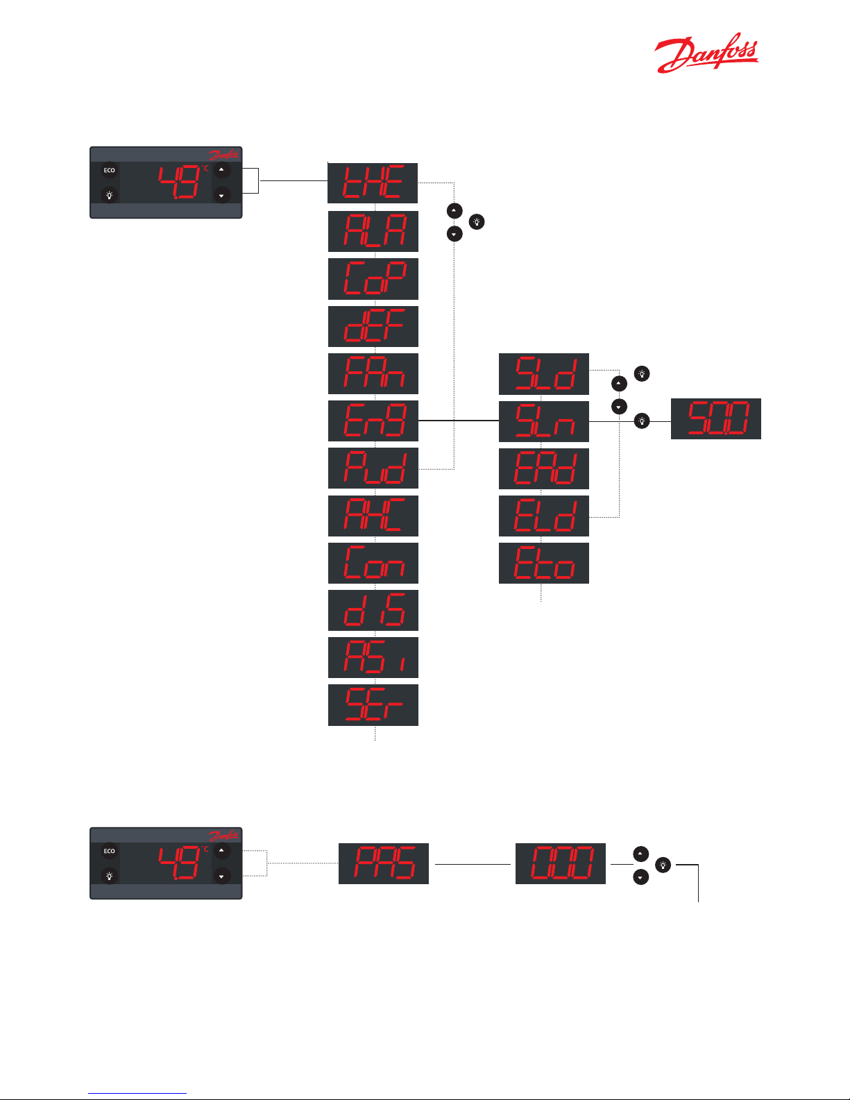
Press and hold 5
sec to access the
menu
1. ) Parameter groups
Lower left button
Lower left button
2.) Parameter names
(scroll through parameters)
(scroll through menu group)
3.) Parameter value
Sub function: Up
1 Click: Temperature setpoint
Sub function: Up
1 Click: Temperature setpoint
Sub function: Up
1 Click: Temperature setpoint
5.3.4 Menu structure
5.3.5 Password protection
Press and hold 5
sec to access the
menu
Password protection on three levels
Level 1: Shop (daily use by shop personnel)
Level 2: Ser (service technician)
Level 3: OEM (OEM programming)
ERC 102 Reference manual – 5 CONTROLLING / NAVIGATION AND ACCESS LEVELS
Page 19

19
The ERC 102 inputs and outputs are configurable by
the customer. Before getting started it is a good idea
to check if all inputs are configured correctly and
match the sensors attached.
Input and output configuration settings are part of
the assignment menu (ASi).
NOTE: Coded sensors will impact on the number of
possible configurations.
For instance: Danfoss supplies only 2-pole defrost
sensors, so input S3 will most likely be used as a
defrost / evaporator temperature sensor input.
Please contact your local Danfoss representative for
information about default settings.
6. CONFIGURATION OF INPUTS AND OUTPUTS
6.1 Changing input and output configuration settings
Example: Input S1 is attached to a temperature sensor. The sensor measures cabinet temperature.
Example: Input S2 is attached a digital on/off sensor which is a door open / closed switch.
There are two steps to inputting the configuration:
1. Define the type of sensor attached to the input:
- Temperature / light / digital
2. Define the application for the sensor:
- Temperature: control / condenser / evaporator
- Light: ECO / display / both
- Digital: door sensor
Sub function: Up
1 Click: Temperature setpoint
Assignments / ASi
Connector inputs: analogue (a), digital (b) Connector outputs (c)
ERC 102 Reference manual – 6 CONFIGURATION OF INPUTS AND OUTPUTS
C
b
a
S1 S2 S3
Page 20

20
ERC menu
code
Default Min Max Unit Conv Unit Scale Default Access
Shop Ser OEM
Assignments ASi
S1 Config S1C Stn Stn dig no -- -- RW
S2 Config S2C Stn Stn dig no -- -- RW
S3 Config S3C Stn Stn dig no -- -- RW
S1 Application S1A SCo nC doo no -- -- RW
S2 Application S2A nC nC doo no -- -- RW
S3 Application S3A nC nC doo no -- -- RW
DI Config diC dio doC dio no -- -- RW
DO1 Config 01C CoP CoP HEt no -- -- RW
DO2 Config o2C dEF 0 Lig no -- -- RW
DO3 Config o3C FAn 0 Lig no -- -- RW
DO4 Config o4C dEF 0 Lig no -- -- RW
Button 1 Short Config b1C noP tP noP no -- -- RW
Button 1 Long Config b1L PoF tP PoF no -- -- RW
Button 2 Short Config b2C dEF tP noP no -- -- RW
Button 3 Short Config b3C tP tP noP no -- -- RW
Button 3 Long Config b3L ECo tP PoF no -- -- RW
Button 4 Short Config b4C tn tP noP no -- -- RW
Button 4 Long Config b4L Lig tP PoF no -- -- RW
Password level1 PS1 0 0 999 no RW RW RW
Password level2 PS2 0 0 999 no -- -- RW
Password level3 PS3 0 0 999 no -- -- RW
Cabinet Light Control
Source
CLC Lig Lig LEC no -- -- RW
Light off delay Lod 0 0 300 no Sec 1 -- -- RW
ERC 102 Reference manual – 6 CONFIGURATION OF INPUTS AND OUTPUTS
Page 21

21
Sub function: Up
1 Click: Temperature setpoint
Sub function: Up
1 Click: Temperature setpoint
Sub function: Up
1 Click: Temperature setpoint
Sub function: Up
1 Click: Temperature setpoint
Sub function: Up
1 Click: Temperature setpoint
Sub function: Up
1 Click: Temperature setpoint
Sub function: Up
1 Click: Temperature setpoint
Sub function: Up
1 Click: Temperature setpoint
S1 Config / S1C
S2 Config / S2C
S3 Config / S3C
Available options are:
Stn for a temperature sensor (values given in Celsius)
Ldr for a light sensor (values given in Luminens)
Dig for a digital sensor with simple on/off indication
D01 Config / D1C
CoP: Direct compressor control
Pil: Pilot Relay (No Zero Cross) – if using pilot relay to control a compressor,
this option must be used instead of CoP
Het: Heating application, inverse output.
DI Config / diC
This is the digital input used for a digital sensor or bus communications.
doC: Door contact, contact closed when door closed
doo: Door contact, contact open when door closed
bus: Modbus communication (used only for KoolProg)
diO: One Wire Communication
S1 Application / S1A
S2 Application / S2A
S3 Application / S3A
Available options are:
nC: Not connected
SCo: Temperature control
EuA: Evaporator temperature
Con: Condenser temperature (Condenser cleaning)
LS1: Light sensor (Ldr), Luminens, dedicated to Eco mode switching detection
LS2: Light sensor (Ldr), Luminens, dedicated to determining LED intensity
LS3: Light sensor(Ldr), Luminens, used for both Eco mode detection and
determining LED intensity
doC: Door contact, contact closed when door closed
doo: Door contact, contact open when door closed
ERC 102 Reference manual – 6 CONFIGURATION OF INPUTS AND OUTPUTS
Page 22
22
Sub function: Up
1 Click: Temperature setpoint
Sub function: Up
1 Click: Temperature setpoint
Sub function: Up
1 Click: Temperature setpoint
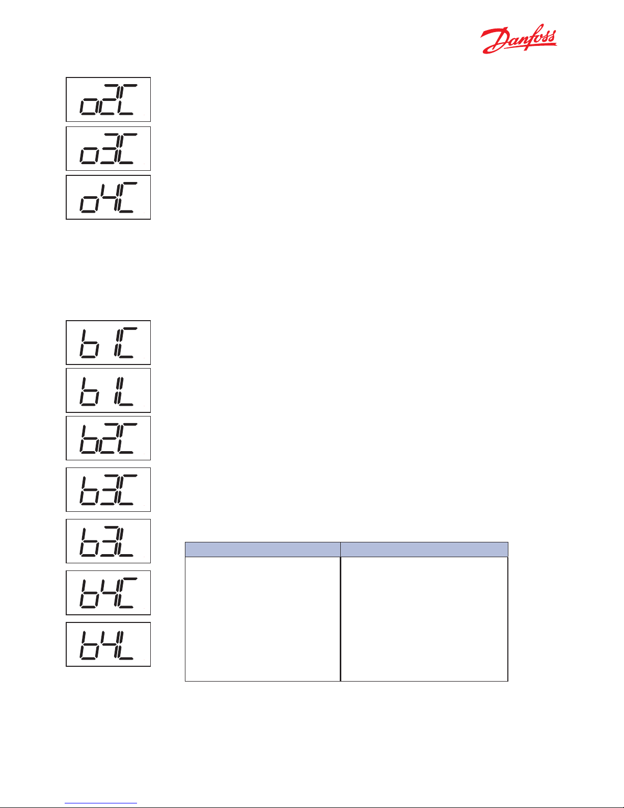
D02 Config / o2C
D03 Config / o3C
D04 Config / o4C
nO: not used
dEF: Electric Defrost Heater / Valve for hot gas
ALA: Alamr Output
Fan: Fan control
LIG: Light control
Button 1 Config (short press) / b1C
Lower left button
Button 1 config (long press) / b1L
Lower left button
Button 2 Config (short press) / b2C
Upper left button
Button 3 Config (short press) / b3C
Upper right button
Button 3 config (long press) / b3L
Upper right button
Button 4 Config (short press) / b4C
Lower right button
Button 4 Config (long press) / b4L
Lower right button
The buttons can be programmed as follows:
Short press function Long Press function
tP: Increase Setpoint
tn: Decrease setpoint
ECo: Toggle Eco mode
Lig: Toggle light
dEF: Toggle defrost
SuP: Toggle Super-Cool /Pull-down
diP : Increase display intensity
din : Decrease display intensity
tP: Increase Setpoint
tn: Decrease setpoint
ECo: Toggle Eco mode
Lig: Toggle light
dEF: Toggle defrost
SuP: Toggle Super-Cool /Pull-down
diP : Increase display intensity
din : Decrease display intensity
Not operating
ERC power ON/OFF
6.2 Program the buttons
ERC 102 Reference manual – 6 CONFIGURATION OF INPUTS AND OUTPUTS
Sub function: Up
1 Click: Temperature setpoint
Sub function: Up
1 Click: Temperature setpoint
Sub function: Up
1 Click: Temperature setpoint
Sub function: Up
1 Click: Temperature setpoint
Sub function: Up
1 Click: Temperature setpoint
Sub function: Up
1 Click: Temperature setpoint
Sub function: Up
1 Click: Temperature setpoint
NOTE: Buttons 1, 3 and 4 can be assigned to operate with 2 functions (short press or long press).
NOTE: Your assignments may not be shown on the printed buttons. We advice to use this functionality
together with the fully integrated mounting model only.
Page 23

23
Password level 1 / PS1
Password Level 2 / PS2
Password Level 3 / PS3
These assign passwords to the three levels of access. The password is a three-digit
number. Access levels are Shop, Service and OEM. You may not therefore have access to change all the passwords. Passwords are entered by using the up and down
arrow buttons.
Danfoss advises against using passwords which are easy to remember or enter, for
example 111, 222, 123 etc.
NOTE: When accessing the controller with 3 wrong password in a sequence ERC will
automatically block access for 15 minutes.
Sub function: Up
1 Click: Temperature setpoint
Sub function: Up
1 Click: Temperature setpoint
Sub function: Up
1 Click: Temperature setpoint
Sub function: Up
1 Click: Temperature setpoint
6.3 Set passwords
6.4 Set lighting function
Cabinet Light Source Control / CLC
This parameter can be set to one of these alternatives to control the light in the
cabinet:
Lig: button only – the light will only come on when the light button on the ERC
102 is pressed (toggle functionality).
Ldo: door (and button if defined) only
LEC: economy (and button if defined) only
Light off delay / Lod
Number of seconds the light will stay on after the
door has been closed.
ERC 102 Reference manual – 6 CONFIGURATION OF INPUTS AND OUTPUTS
Page 24

24
This chapter details all user-accessible parameters
in ERC 102 software 5.05.
NOTE: Incorrect parameter settings can lead to
inadequate cooling, excessive energy consumption,
unnecessary alarms and in the case of temperaturesensitive food storage, breaches in food hygiene
principles and regulations. Only a trained operator
should make changes to parameters.
INFO! Some parameters may be hidden to you. When
scrolling through menus, the parameters available will
have been pre-determined using KoolProg software.
Your access level will determine which parameters you
can view and edit.
The access level can be set separately for each
parameter using KoolProg software. There are three
levels of access – 1, 2 and 3. Level 1 is for shop access,
level 2 for technicians and level 3 for OEMs. The access
levels cannot be set using the buttons. Passwords for
the different levels can however be altered for the
level of access you have – for example a level 2 user
can change the password for level 1 and level 2 but
not level 3.
ERC 102 can handle both Celsius and
Fahrenheit. Changing from C to F and vice-versa
is done in the Display menu. When the change
is made, all temperature values are automatically
re-calculated and updated in all other
parameters accordingly.
7. PARAMETERS
7.1 Thermostat / tHE
Sub function: Up
1 Click: Temperature setpoint
ERC menu
code
Default Min Max Unit
Conv
Unit Scale Default Access
Shop Ser OEM
Thermostat tHE
Set point adjustment ratio SPr 0.5 0.0 1.0 no .1 -- -- RW
Differential diF 2.0 0.0 20.0 C/F r K .1 -- RW RW
High Set Point HSE 50.0/122.0 -50.0/122.0 80.0/176.0 C/F a °C/°F .1 -- RW RW
Low Set Point LSE -35.0/-31.0 -35.0/-31.0 80.0/176.0 C/F a °C/°F .1 -- RW RW
Air Temp Adj. tAd 0.0/0.0 0.0/0.0 20.0/36.0 C/F r K/°R .1 -- -- RW
ERC 102 Reference manual – 7 PARAMETERS
Page 25

25
Set point adjustment ratio / SPr
The default value is set to 0.5 and the parameter is hidden by default.
Spr defines the position of the setpoint in relation to cut-in and cut-out.
Spr = 0,5 sets the setpoint mid between cut-in and cut-out. Spr = 0 sets
the setpoint at the cutout. Spr =1 sets the setpoint at cut-in.
Set point / StP
StP is visible with KoolProg software only. This parameter defines the desired
temperature (set point). In standard operation the set point is changed by
simply pressing the “temperature up / down” buttons on ERC102; for laboratory
and assembly line you may opt for software controlled set point adjustment
(speed improvement)
Differential / diF
This defines the difference between the cut-out and the cut-in. The desired
temperature is determined by SPr and diF.
Sub function: Up
1 Click: Temperature setpoint
Sub function: Up
1 Click: Temperature setpoint
Sub function: Up
1 Click: Temperature setpoint
High Set Point / HSE
Low Set Point / LSE
These parameters define the temperature range limit of the controller. Once set,
the desired temperatue (setpoint) can not go above HSE or below LSE.
LSE Sets the minimum value for the set point
HSE Sets the maximum value for the set point
Cut-in and cut-out are automatically calculated from the desired setpoint (set
bybuttons on the control) and the differential. By default, cut-out and cut-in are
0,5*DiF above or below the desired temperature.
Example: The desired average temperature in the cabinet is 5 degrees, and the
differential is set to 2 degrees:
Sub function: Up
1 Click: Temperature setpoint
Sub function: Up
1 Click: Temperature setpoint
ERC 102 Reference manual – 7 PARAMETERS
Air Temperature Adjustment / tAd
This parameter is a relative value and allows adjustment of the
control sensor temperature.
For instance, at a measured temperature of 7*C and tAd set to -2K,
the input from the control sensor will be 5*C instead.
Sub function: Up
1 Click: Temperature setpoint
Page 26

26
Sub function: Up
1 Click: Temperature setpoint
7.2 Alarms / ALA
ERC menu
code
Default Min Max Unit
Conv
Unit Scale Default Access
Shop Ser OEM
Alarm ALA
High Alarm delay Htd 30 0 240 no min 1 -- RW RW
Low Alarm delay Ltd 0 0 240 no min 1 -- RW RW
High Temp Alarm HAt 15.0/59.0 -50.0/-58.0 80.0/176.0 C/Fa °C/°F .1 -- RW RW
Low Temp Alarm LAt -50.0/-58.0 -50.0/-58.0 80.0/176.0 C/F a °C/°F .1 -- RW RW
Pulldown delay Pdd 240 0 960 no min 1 -- RW RW
Door Open delay dod 2 0 60 no min 1 -- RW RW
Alarm Buzzer Duration Abd 0 0 999 no min 1 -- RW RW
Auto Clearance of
Alarm/Error
ACA yES no yES no 1 -- RW RW
ERC 102 Reference manual – 7 PARAMETERS
Page 27

27
High Temp Alarm / HAt
Low Temp Alarm / Lat
High temperature alarm and low temperature alarm allow for individual alarm
setpoints. Both are absolute values. By setting HAt to the maximum value and LAt
to the minimum value, alarms will be deactivated.
Sub function: Up
1 Click: Temperature setpoint
Sub function: Up
1 Click: Temperature setpoint
High Alarm Delay / Htd
Low Alarm Delay / Ltd
These parameters express the number of minutes to wait before sounding an
alarm once the High/Low Temp Alarm temperature is reached. Immediately prior
to the alarm sounding, another check of the temperature is made to see if the
temperature is still in the alarm zone; if it is not, the then the alarm is not sounded.
In most situations, the Low Alarm Delay will be set to 0 to warn about too low a
temperature immediately.
Pulldown Delay / Pdd
Normally, it is not necessary or desirable to sound an alarm during a pull down
(the initial phase of reaching the desired temperature). This parameter prevents
the High Temp Alarm HAt sounding during pull down and after a defrost for the
number of minutes set for the parameter.
NOTE: It does not apply to the Low Temp Alarm LAt.
Door Open Delay / dod
It is possible to indicate to customers that a door has accidentally been left open.
This parameter sets the delay in minutes before the alarm sounds. This is useful in
environments where customers / users may hold the door open while making their
selection. If the door is closed again before the set number of minutes is reached,
the alarm does not sound.
NOTE: A door sensor is required if this parameter is to be activated.
Alarm Buzzer Duration / Abd
The ERC 102 alarm sounds for 10 seconds, followed by silence for 50 seconds. One
alarm sequence therefore lasts 60 seconds. These values cannot be changed. This
parameter determines how long in minutes an audible alarm will continue while
there is still a reason to have an alarm. If set to 999, the alarm will continue to
sound until the reason for the alarm is cleared – for example the temperature has
dropped enough or the door closed. In some cases, it may be necessary for a user
or technician to take action in order to clear the alarm. If set to 0, the alarm will
never sound.
Sub function: Up
1 Click: Temperature setpoint
Sub function: Up
1 Click: Temperature setpoint
Sub function: Up
1 Click: Temperature setpoint
Sub function: Up
1 Click: Temperature setpoint
Sub function: Up
1 Click: Temperature setpoint
ERC 102 Reference manual – 7 PARAMETERS
Page 28

28
Auto Clear of Alarm / Error / ACA
If this parameter is set to nO:
The alarm status will not disappear automatically even if the condition which
caused the alarm is no longer valid or present.
If set to yES:
As soon as the condition which caused the alarm is no longer valid or present, the
alarm status will automatically change back to inactive. There will be no trace of
the alarm having occurred.
In general, Glass Door Merchandise applications will be set to yES and Commercial
Fridges and Freezers set to nO. For example, if the temperature goes too high for
a period there may be food safety considerations in a freezer containing food but
not in a fridge with cold drinks.
7.3 Compressor / CoP
ERC menu
code
Default Min Max Unit
Conv
Unit Scale Default Access
Shop Ser OEM
Compressor CoP
Min run time Crt 0 0 30 no min 1 -- RW RW
Min Stop time CSt 0 0 30 no min 1 -- RW RW
Max Off time Cot 0 0 480 no min 1 -- -- RW
Error run time Ert 0 0 60 no min 1 -- -- RW
Error stop time ESt 1 0 60 no min 1 -- -- RW
Minimum cut-in voltage uLi 0 0 270 no Vac 1 -- -- RW
Minimum cut-out voltage uLo 0 0 270 no Vac 1 -- -- RW
Maximum voltage uHi 270 0 270 no Vac 1 -- -- RW
Power On Delay Pod 300 0 300 no Sec 1 -- RW RW
Power Factor PFA 0 -90 90 no Degree 1 -- -- RW
Initial cut in iCi no no yes no 1 -- R- RW
Compressor door open delay Cdd 0 0 15 no min 1 -- RO RW
Sub function: Up
1 Click: Temperature setpoint
Sub function: Up
1 Click: Temperature setpoint
ERC 102 Reference manual – 7 PARAMETERS
Page 29

29
Minimum Run Time / Crt
This parameter is a number of minutes from 0 to 30.
It determines the minimum number of minutes the compressor must run before a
Temperature cut-out can take effect. For example, if the temperature sensor indicated that the cut-out temperature has been reached, but the number of minutes
set in this parameter have not elapsed since the compressor last started, then the
compressor will continue. It will only stop once the duration given by Crt has been
reached – provided the temperature is still low enough.
Crt thus overrides the cut-out.
Minimum Stop Time / CSt
This parameter is a number of minutes from 0 to 30.
It determines the minimum number of minutes the compressor must remain idle
before a Temperature cut-in can take effect. For example, if the temperature sensor
indicates that the cut-in temperature has been reached, but the number of minutes
set in this parameter have not elapsed since the compressor last stopped, then the
compressor will stay off. It will only start once the duration given by CSt has been
reached – provided the temperature is still high enough.
CSt thus overrides the cut-in.
Maximum Off Time/ Cot
This is the maximum time in minutes the compressor is allowed to idle – up to 480
minutes. Cot is set to zero by default (inactive). If ERC102 is to be used on a draft
beer (ice bank) application, this parameter can be used to control the ice thickness.
Error Run Time / Ert
Error Stop Time / ESt
These two parameters only become active in the unlikely event of a broken temperature sensor. They are then used to run the application in safety mode. At the
same time the sensor error will be shown in the display.
Ert and ESt values are based on OEM experience and are by default inactive.
Ert and ESt define the duration the compressor will run (Ert) and be idle (ESt).
Example: Ert = 4 [min] and ESt = 16 [min] will provide an average cooling system
activity of 20%.
Sub function: Up
1 Click: Temperature setpoint
Sub function: Up
1 Click: Temperature setpoint
Sub function: Up
1 Click: Temperature setpoint
Sub function: Up
1 Click: Temperature setpoint
Sub function: Up
1 Click: Temperature setpoint
ERC 102 Reference manual – 7 PARAMETERS
Page 30

30
Power On Delay / Pod
This is the delay in seconds between power-on and the compressor being
activated. Depends on the Power on Temperature setting as explained below.
Power Factor / PFA
This value is hidden by default. The parameter is used by the Zero Cross function
to optimize the switching position of the relay contact.
Warning:
Do not change without first consulting your local
Danfoss representative.
Power on Temperature / PoT
This parameter is used to accelerate the first application test on the OEM assembly
line; if the cabinet temperature is higher than this parameter the Power On Delay is
overruled and the outputs are activated without delay.
Sub function: Up
1 Click: Temperature setpoint
Sub function: Up
1 Click: Temperature setpoint
Sub function: Up
1 Click: Temperature setpoint
Minimum cut-in voltage / uLi
Minimum cut-out voltage / uLo
Maximum voltage / uHi
These three parameters provide voltage protection to the compressor. Start by
setting uHi, followed by uLo and uLi.
uLi: When the compressor is due to start, the voltage of the power supply will be
checked and the compressor will only be allowed to start if it is at least the value
given in this parameter.
uLo: When the compressor is running, it will be switched off if the voltage goes
below that given in this parameter.
uHi: When the compressor is running, it will be switched off if the voltage exceeds
that given in this parameter. If the compressor is already stopped, it will remain
switched off.
Sub function: Up
1 Click: Temperature setpoint
Sub function: Up
1 Click: Temperature setpoint
Sub function: Up
1 Click: Temperature setpoint
ERC 102 Reference manual – 7 PARAMETERS
Compressor Door Open Delay / Cdd
This parameter sets the delay in minutes before the compressor stops when the
door is opened. If set to zero, the function is disabled.
Initical Cut-in / iCi
if the control temperature is between cut-in and cut-out at power up customers can
determine if the compressor shall start immediatly (yes) or wait for cut-in temperature to start (no).
Sub function: Up
1 Click: Temperature setpoint
Page 31

31
7.4 Defrost / dEF
Sub function: Up
1 Click: Temperature setpoint
ERC menu
code
Default Min Max Unit
Conv
Unit Scale Default Access
Shop Ser OEM
Defrost dEF
Def type dFt no no Hgd no -- RW RW
Def reset temp drt 5 0 80 C/F a °C 1 -- RW RW
Def Min Interval dii 6 0 96 no hour 1 -- RW RW
Def Max Interval dAi 7 0 96 no hour 1 -- RW RW
Def Min Time dit 5 0 240 no min 1 -- RW RW
Def Max time dAt 30 0 480 no min 1 -- RW RW
Drip off time dot 0 0 60 no min 1 -- -- RW
Fan delay after Defrost Fdd 0 0 60 no min 1 -- -- RW
Fan start Temp Ftd 25.0/77.0 -25.0/13.0 25.0/77.0 C/F a °C/°F .1 -- -- RW
Defrost Fan on dFA no no yES no 1 -- -- RW
Initial Defrost Interval idi 3 0 96 no hour 1 -- -- RW
Initial Defrost Duration idd 100 0 999 no 1 -- RW RW
Defrost on compressor
time
dCt no no yES no 1 -- -- RW
ERC 102 Reference manual – 7 PARAMETERS
Note: ERC controllers feature Safe Defrost
functionality (patents pending) by default. This function ensures proper defrost
under poor power conditions.
For more details please contact Danfoss.
Page 32
32
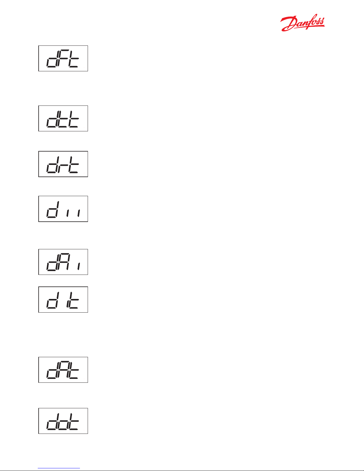
Defrost Type / dFt
When set to nO, the defrost function is disabled and no automatic defrosting
will occur.
When set to EL or nAt, electrical, natural or off-cycle defrosting is used. An additional setting of Hgd (hot gas defrosting) is available.
Terminate Temperature / dtt
This parameter defines at what temperature the defrost cycle will stop.
The temperature is given by the evaporator sensor or by the cabinet
temperature sensor if no evaporator sensor is used.
Defrost reset temperature / drt
The defrost counter is saved and restored at power-up, but if the temperature
sensor, used for defrost, is higher than this value at power-up, it is assumed that
the evaporator is free of ice and the defrost counter will be cleared.
Minimum Interval / dii
This parameter can be set to between 0 and 96 hours and defines the minimum
time period between the start of two defrost cycles. Once the minimum interval
has expired, the defrost cycle will start at the following cut-out or once the maximum interval dAi has been reached.
Maximum Interval / dAi
This parameter can be set to between 0 and 96 hours and defines the maximum
time period between the start of two defrost cycles.
Minimum Time / dit
This parameter can be set to between 0 and 240 minutes and defines the minimum duration of a defrost cycle. During this period, the ERC 102 will not check
the temperature. Once the minimum time has expired, the temperature will be
checked and if the Terminate Temperature dtt has been reached, the defrost
cycle will end. If dtt has not been reached, defrost will continue until either dtt is
reached or the Maximum Time dAt reached, whichever occurs first.
Maximum Time / dAt
This parameter can be set to between 0 and 240 minutes and defines the maximum duration of a defrost cycle.
The ERC 102 will not allow a maximum time to be entered which is less than the
minimum time, or a minimum time which is more than the maximum time.
Drip Off Time / dot
This is only used with an electrical heater. This parameter can be set to between
0 and 60 minutes and defines how long the delay is between the heater being
switched off and the compressor starting again.
Sub function: Up
1 Click: Temperature setpoint
Sub function: Up
1 Click: Temperature setpoint
Sub function: Up
1 Click: Temperature setpoint
Sub function: Up
1 Click: Temperature setpoint
Sub function: Up
1 Click: Temperature setpoint
Sub function: Up
1 Click: Temperature setpoint
Sub function: Up
1 Click: Temperature setpoint
ERC 102 Reference manual – 7 PARAMETERS
Sub function: Up
1 Click: Temperature setpoint
Page 33

33
Fan Delay after Defrost / Fdd
This parameter can be set to between 0 and 60 seconds and defines how
long the delay is between the start of the compressor after defrost and the
fan starting again.
Fan Start Temperature / Ftd
This only applies if an evaporator temperature sensor is fitted. This parameter
determines at what evaporator temperature the fan will start after a defrost cycle
is complete.
If the time set in Fdd occurs before the temperature set in Ftd, the fan will start
in line with Fdd. If the temperature set in Ftd occurs first, then the fan will start in
line with Ftd. It is therefore a case of whichever parameter’s setting is reached first
which determines when the fan starts.
Defrost Fan On / dFA
Set to yES, the fan will constantly run during defrost cycles.
Set to nO, the fan will not run during defrost cycles.
Initial Defrost Interval / idi
The initial defrost interval determines the time for first defrost after power-up. The
initial defrost is mainly intended for factory testing of the defrost functionality and
can be set to expire after a number compressor cycles according to the setting
of parameter idd . During normal operation, the defrost counter will be saved in
memory and restored after power loss, making the initial defrost unnecessary.
Defrost On Compressor Time / dCt
If this parameter is set to yES, then defrost cycles are based on the total time
the compressor has been running.
If this parameter is set to nO, then defrost cycles are related to elapsed time,
regardless of how long and how often the compressor has been on.
Sub function: Up
1 Click: Temperature setpoint
Sub function: Up
1 Click: Temperature setpoint
Sub function: Up
1 Click: Temperature setpoint
Sub function: Up
1 Click: Temperature setpoint
Sub function: Up
1 Click: Temperature setpoint
ERC 102 Reference manual – 7 PARAMETERS
Initial Defrost Duration / idd
The initial defrost duration is the number of compressor cycles before the initial
defrost is deactivated.
0: idi No initial defrost
1-998: number of compressor cycles before deactivation
999: Initial defrost always active.
Sub function: Up
1 Click: Temperature setpoint
Page 34

34
Fan Always On / FAo
If this parameter is set to yES, all other parameters in this section
about the fan are deactivated.
NOTE: If FAo is set to nO, then the following parameters will be applied.
Fan On Delay / Fod
Fan Stop Delay / FSd
If this parameter and FSd are both set to zero then the fan runs whenever the
compressor runs.
Fod defines the fan delay
(in seconds) after a compressor
cut-in.
FSd defines the fan delay after a
compressor cut-out.
7.5 Fan / FAn
ERC menu
code
Default Min Max Unit
Conv
Unit Scale Default Access
Shop Ser OEM
Fan FAn
Fan always On FAo yES no yES no 1 -- -- RW
Fan stop time on door open Fdt 999 0 999 no Sec 1 -- -- RW
Fan On Delay Fod 0 0 240 no Sec 1 -- -- RW
Fan Stop delay FSd 0 0 240 no Sec 1 -- -- RW
Fan On Cycle FoC 0 0 960 no Sec 1 -- -- RW
Fan Stop Cycle FSC 0 0 960 no Sec 1 -- -- RW
The fan parameters are all related to energy saving,
and to redistribution of air within the cabinet to
reduce the amount of energy spent on cooling.
Fan On Cycle / FoC
Fan Stop Cycle / FSC
When the compressor is off, and FoC or FSC are not zero, the fan runs in cycles
according to FoC and FSC.
Example: FoC = 120 [sec] and FSC = 120 [sec] means that the fan runs for half the
time when the compressor is off. When the compressor is on, the fan is always on
(according to FAo and Fod).
Sub function: Up
1 Click: Temperature setpoint
Sub function: Up
1 Click: Temperature setpoint
Sub function: Up
1 Click: Temperature setpoint
Sub function: Up
1 Click: Temperature setpoint
Sub function: Up
1 Click: Temperature setpoint
Sub function: Up
1 Click: Temperature setpoint
ERC 102 Reference manual – 7 PARAMETERS
Fan stop time on door open: Fdt
The maximum time the fan will be stopped after the door has been opened.
0: fan will not stop under opening
1-998: number of seconds fan will be stopped during door opening
999: fan will be stopped as long as the door is open
Sub function: Up
1 Click: Temperature setpoint
Page 35

35
7.6 Energy Management / Eng
Shop Light Day / SLd
Shop Light Night / SLn
These parameters are set as the percentage of the maximum light and determine
when the device moves into or out of Eco mode for power-saving purposes.
SLd is the amount of ambient light which will cause the device to move to normal /
serving mode from Eco mode (normally occurs in the morning).
SLn is the amount of ambient light which will cause the device to move to Eco
mode from normal / serving mode (normally occurs in the evening).
NOTE: Some of these parameters require the installation of the Danfoss Ambient Light Sensor.
The Danfoss USB Gateway in combination with KoolProg software allows for real time measurement of the
current light intensity. Danfoss recommends testing and adjusting SLd and SLn values according to customers’ specific needs.
ERC menu
code
Default Min Max Unit
Conv
Unit Scale Default Access
Shop Ser OEM
Energy management Eng
Shop Light Day SLd 50 0 100 no % 1 RW RW RW
Shop Light Night SLn 50 0 100 no % 1 RW RW RW
Eco Activity delay EAd 0 0 360 no min 1 RW RW RW
Eco Light delay ELd 5 0 10 no min 1 -- RW RW
Light Blocking delay Lbd 0 0 360 no min 1 -- RW RW
Eco Temperature Offset Eto 4.0/7.2 0,0 10.0/18.0 C/F r K/°R .1 -- RW RW
Eco Door Delay / EAd
The transition from Eco to normal mode and vice versa occurs on a change in light
level or door activity.
NOTE: A door sensor is required.
Sub function: Up
1 Click: Temperature setpoint
Sub function: Up
1 Click: Temperature setpoint
Sub function: Up
1 Click: Temperature setpoint
Sub function: Up
1 Click: Temperature setpoint
ERC 102 Reference manual – 7 PARAMETERS
Eco Light Delay / ELd
This parameter causes a delay to the switch from Normal to Eco mode when the
shop lights are switched on or off. The ambient light sensor detects the change in
light level and causes a switch mode. With this parameter set to zero, the switch
off mode occurs immediately. If not set to zero (max: 10 minutes), then the change
will be delayed by the number of minutes set.
Sub function: Up
1 Click: Temperature setpoint
Page 36

36
Light Blocking delay / Lbd
If the cooler is placed where the ambient light is unstable, the ambient light sensor
can cause the cooler to toggle between ECO and normal mode.
The light blocking delay disables the light-sensor for a given time after ambient
light change from bright to dark, so that the cooler stays in ECO mode for at least
this time. When the cooler is in serving or pull-down mode, the light sensor is
de-activated and a change to ECO mode will be determined by the door-sensor.
0: No blocking of the ambient light sensor.
Eco Temperature Offset / Eto
This parameter gives a relative temperature in degrees. It is the difference in
temperature for Eco mode operation compared to Normal mode.
NOTE: Setting a temperature offset may be illegal in
some jurisdictions.
Pull down (sometimes known as Super Cool) is
a procedure for improving cooling performance,
accelerating the time used to reach the desired
temperature. Pull Down settings overrule all
other settings.
7.7 Pull Down / Pud
Sub function: Up
1 Click: Temperature setpoint
Sub function: Up
1 Click: Temperature setpoint
ERC menu
code
Default Min Max Unit
Conv
Unit Scale Default Access
Shop Ser OEM
Pull Down Pud
Pull-down Initiate
Temperature
Pit 50.0/122.0 -40.0/-40.0 50.0/122.0 C/F a °C/°F .1 -- -- RW
Pull-down Cycling PCy 30 0 360 no min 1 -- -- RW
Pull-down defrost Interval Pdi 15 0 48 no hour 1 -- -- RW
Pull-down duration Pdd 24 0 48 no hour 1 -- -- RW
Pull-down limit temp PLt 0.0/32.0 -55.0/-67.0 55.0/131.0 C/F a °C/°F .1 -- -- RW
Pull-down reduction
temp △t
Prt 0.1/0.2 0,0 10.0/16.0 C/F r K/°R .1 -- -- RW
ERC 102 Reference manual – 7 PARAMETERS
Page 37

37
Pull Down Cycling / PCy
This is the duration in minutes of the compressor cycling at the reduced set point
temperature. Once the desired Pull Down Limit Temperature PLt has been reached
during Pulldown, the compressor will continue to cycle on / off for the duration of
PCy. At the end of the period defined by PCy, the Set Point temperature will return
to normal and Pulldown will cease.
Pull Down Initiate Temperature / Pit
This parameter indicates the temperature which causes a pull down to start. If the
temperature measured inside the cabinet exceeds this value for longer than one
hour, then pull down will start. The compressor will have already cut-in, so the only
effect is to stop defrost cycles until the desired temperature is reached. The period
of one hour is fixed and cannot be altered.
Pull Down Defrost Interval / Pdi
Even though most applications do not need Defrost during Pull Down, an extended
defrost during pull down can be applied. This is the time between defrost cycles
during Pull Down. It is measured in hours and can be up to 48 hours. During Pull
Down, this setting overrides the Defrost Interval and Defrost Time settings (see the
Defrost section).
Pull Down Duration / Pdd
You can choose to limit the maximum Pull Down time. Once this time value
(max. 48 hours) is reached, Pull Down will stop regardless of whether the desired
pull-down temperature has been reached.
Pull Down Limit Temperature / PLt
This parameter sets the minimum allowed temperature during pull-down,
In order to protect valuable contents you must always specify the absolute minimum temperature allowed in your application.
For Glass Door Merchandisers 0°C/32°F protects bottles from freezing;
for Commercial Fridges you may opt for a slightly higher temperature (e.g. 2°C)
Sub function: Up
1 Click: Temperature setpoint
Sub function: Up
1 Click: Temperature setpoint
Sub function: Up
1 Click: Temperature setpoint
Sub function: Up
1 Click: Temperature setpoint
Sub function: Up
1 Click: Temperature setpoint
Sub function: Up
1 Click: Temperature setpoint
ERC 102 Reference manual – 7 PARAMETERS
Pull Down Reduction Temperature ∆t / Prt
ERC 102 calculates a lower set-point during Pull Down mode to increase the cooling capacity of your appliance. For each hour the cabinet temperature is above the
Pull down initiate temperature, the set-point is reduced with the value of Prt.
Page 38

38
Automatic Heater Mode Enable / AuH
This setting is normally set to nO.
When set to yES, parameters End and Hdi apply.
Energy Mode Delay / End
This is the delay in minutes between the heater and the compressor operation.
The heater is not allowed to start until this number of minutes has expired after
the compressor has cut out and vice versa.
Automatic Heater Control applies reverse cooling
mode (heating) to your refrigeration appliance.
This feature requires:
A) that your appliance is exposed to ambient temperatures below the desired temperature in your
cabinet (e.g. very cold climates and outdoor use)
B) a special heater (for example a large defrost
heater) built in to your appliance.
7.8 Automatic Heater Control / AHC
ERC menu
code
Default Min Max Unit
Conv
Unit Scale Default Access
Shop Ser OEM
Auto-Heater Control AHC
Automatic heater mode
enable
AuH no no yES no -- -- RW
Energy mode delay End 60 0 360 no min 1 -- -- RW
Heater displacement
temperature
Hdi 2.0/3.0 0.0/0.0 50.0/90.0 C/F r K/oR .1 -- -- RW
Sub function: Up
1 Click: Temperature setpoint
Sub function: Up
1 Click: Temperature setpoint
Sub function: Up
1 Click: Temperature setpoint
Heater Displacement Temperature / Hdi
This is the temperature relative to (below) the desired temperature.
Sub function: Up
1 Click: Temperature setpoint
ERC 102 Reference manual – 7 PARAMETERS
Page 39

39
NOTE: A condensor temperature sensor is
required to use these parameters.
Condenser protection is generally used in dusty
environments where the condenser may accumulate a layer of dust or dirt and therefore be at risk of
overheating.
7.9 Condenser Protection / Con
ERC menu
code
Default Min Max Unit
Conv
Unit Scale Default Access
Shop Ser OEM
Condenser Protection Con
Condenser Alarm Limit CAL 80/176 0/32 85/185 C/F a °C/°F 1 -- -- RW
Condenser Block Limit CbL 85/185 0/32 85/185 C/F a °C/°F 1 -- -- RW
Condenser OK limit CoL 60/140 0/32 85/185 C/F a °C/°F 1 -- -- RW
Condenser Low Limit CLL 5 -20/-4 20/68 C/F a °C/°F 1 -- -- RW
Condenser Alarm Limit / CAL
This parameter sets the temperature for the condenser at which an alarm will
be generated.
Condenser Block Limit / CbL
This parameter sets the temperature which if reached will cause the compressor
to switch off.
Condenser OK Limit / CoL
This parameter sets the temperature at which the compressor is allowed to
start again after the temperature set in CbL above has been exceeded and the
compressor stopped.
Condenser Low Limit / CLL
This parameter sets the lowest (condenser) temperature at which the
compressor is allowed to start.
Sub function: Up
1 Click: Temperature setpoint
Sub function: Up
1 Click: Temperature setpoint
Sub function: Up
1 Click: Temperature setpoint
Sub function: Up
1 Click: Temperature setpoint
Sub function: Up
1 Click: Temperature setpoint
ERC 102 Reference manual – 7 PARAMETERS
Page 40

40
ERC menu
code
Default Min Max Unit
Conv
Unit Scale Default Access
Shop Ser OEM
Display diS
Display Unit CFu -C -C -F no RW RW RW
Display Resolution rES 0.1 0.1 1 no -- -- RW
Display Range Limit rlt no no yES no -- -- RW
Display Delay ddL 0 0 10 no Sec 1 -- -- RW
Display Offset doF 0.0/0.0 -10.0/-18.0 10.0/18.0 C/F r K/oR -- -- RW
Lock-time After defrost dLt 15 0 60 no min 1 -- -- RW
Show Economy state SEC no no yES no -- -- RW
Show Pull Down state SSC no no yES no -- -- RW
Show Defrost SdF yES no yES no -- -- RW
Display Intensity din 10 1 10 no 1 RW RW RW
This section deals with parameters for the display.
NOTE: Some display parameters can be set in such as way that they may be illegal in some jurisdictions. Please
check local legislation.
Display Unit / CFu
This parameter sets the display to Fahrenheit or Celsius. Switching from one to the
other will cause all temperature settings to be automatically updated accordingly.
Display Range Limit / rLT
In some Point of Sales applications you may want to show the desired instead of
the real temperature. This parameter sets whether the displayed temperature is
the actual temperature or whether it is restricted to the cut-in / cut-out limits. Set
to nO means that the actual temperature will de displayed.
The parameter is set to nO by default.
Display Resolution / rES
This parameter can be set to 0.1, 0.5 or 1 and affects the way the temperature is
displayed. With the parameter set to 1, the display will only ever show temperatures rounded to the nearest whole degree. At 0.5, it will round the temperature to
the nearest half degree for display.
For example, 3.3 degrees will be shown in the display as 3.5 degrees and 3.9 as 4.0.
With the parameter set to 0.1, no rounding occurs.
This parameter does not affect the temperature itself, merely the display.
7.10 Display / diS
Sub function: Up
1 Click: Temperature setpoint
Sub function: Up
1 Click: Temperature setpoint
Sub function: Up
1 Click: Temperature setpoint
Sub function: Up
1 Click: Temperature setpoint
ERC 102 Reference manual – 7 PARAMETERS
Page 41

41
Display Delay/ ddL
In order to provide a realistic temperature appearance for an application,
a display delay can be set.
The parameter sets the time constant τ (tau) of the moving average filter
for the display.
Physically, one time constant represents the time it takes the system’s
step-response to reach 66% of its final value and five time-constants the time
it takes to reach 99% of its final value.
The parameter can be set from 0 to 10 minutes.
Display Offset / doF
This parameter is a relative value and allows the temperature displayed to be
different to the temperature measured. For instance, at a measured temperature
of 7°C and doF set to -2K, the displayed temperature will be 5°C instead.
Lock Time After Defrost / dLt
In order not to show a rising temperature during defrosting, the displayed temperature is locked at the temperature shown at the start of the defrost cycle for the
number of minutes set in this parameter.
0 = no lock.
Show Economy State / SEC
If set to yES, this parameter causes the display to show ECO when the system is in
ECO mode.
If set to nO, the temperature continues to be displayed.
Show Pull down state / SSC
If set to yES, this parameter causes the display to show SC when the system is in
Pull Down mode.
If set to nO, the temperature continues to be displayed.
Show Defrost / SdF
If set to yES, this parameter causes the display to show DEF when the system is in
defrost mode. If set to nO, the temperature continues to be displayed.
Sub function: Up
1 Click: Temperature setpoint
Sub function: Up
1 Click: Temperature setpoint
Sub function: Up
1 Click: Temperature setpoint
Sub function: Up
1 Click: Temperature setpoint
Sub function: Up
1 Click: Temperature setpoint
Sub function: Up
1 Click: Temperature setpoint
ERC 102 Reference manual – 7 PARAMETERS
Page 42

42
Display Intensity / din
ERC 102 can have its display intensity (brightness) set in one of two ways:
A) with a Danfoss ambient light sensor attached, the brightness of the display is
adjusted automatically according to the ambient light level (see the Assignments
section)
B) when no ambient light sensor is attached, the display intensity can be set to
a fixed intensity.
Both options are on a scale of 1 to 10, where 10 is the brightest.
7.11 Assignments / ASi
ERC menu
code
Default Min Max Unit
Conv
Unit Scale Default Access
Shop Ser OEM
Assignments ASi
S1 Config S1C Stn Stn dig no -- -- RW
S2 Config S2C Stn Stn dig no -- -- RW
S3 Config S3C Stn Stn dig no -- -- RW
S1 Application S1A SCo nC doo no -- -- RW
S2 Application S2A nC nC doo no -- -- RW
S3 Application S3A nC nC doo no -- -- RW
DI Config diC dio doC dio no -- -- RW
DO1 Config o1C CoP CoP HEt no -- -- RW
DO2 Config o2C dEF 0 Lig no -- -- RW
DO3 Config o3C FAn 0 Lig no -- -- RW
DO4 Config o4C Lig 0 Lig no -- -- RW
Button 1 Short Config b1C noP tP noP no -- -- RW
Button 1 Long Config b1L PoF tP PoF no -- -- RW
Button 2 Short Config b2C dEF tP noP no -- -- RW
Button 3 Short Config b3C tP tP noP no -- -- RW
Button 3 Long Config b3L ECo tP PoF no -- -- RW
Button 4 Short Config b4C tn tP noP no -- -- RW
Button 4 Long Config b4L Lig tP PoF no -- -- RW
Pass-word level1 PS1 0 0 999 no RW RW RW
Pass-word level2 PS2 0 0 999 no -- RW RW
Pass-word level3 PS3 0 0 999 no -- -- RW
Cabinet Light Control
Source
CLC Lig Lig LEC no -- -- RW
Door close delay dCd 0 0 300 no Sec 1 -- -- RW
Light off delay Lod 0 0 300 no Sec 1 -- -- RW
Sub function: Up
1 Click: Temperature setpoint
For more details on how to set parameters
- see chapter 6.
ERC 102 Reference manual – 7 PARAMETERS
Page 43

43
The parameters in the following section are READ
ONLY and cannot be changed by the user. They provide information for technicians and OEM users.
NOTE: the only parameters that can be configured are:
oEL, oEn, oEH.
These parameters allow OEMs to enter their own
product code.
7.12 Service Information / Ser
Sub function: Up
1 Click: Temperature setpoint
ERC 102 Reference manual – 7 PARAMETERS
ERC menu
code
Default Min Max Unit
Conv
Unit Scale Default Access
Shop Ser OEM
Service SEr
DI Sdi --- oFF on no -- R- R-
Voltage value uAC --- 0 270 no Vac 1 -- R- R-
DOs Status ouS --- IIII IIII no -- R- R-
Relay 1 counter rL1 --- 0 999 no 1000 1000 -- R- R-
Relay 2 counter rL2 --- 0 999 no 1000 1000 -- R- R-
Relay 3 counter rL3 --- 0 999 no 1000 1000 -- R- R-
Relay 4 counter rL4 --- 0 999 no 1000 1000 -- R- R-
interval Counter int --- 0 999 no min 1 -- R- R-
Defrost time counter dnt --- 0 999 no min 1 -- R- R-
Door open counter ont --- 0 999 no 1 1 -- R- R-
SW version Fir SWVER -32768 32767 no R- R- R-
HW version HAr HWVER -32768 32767 no R- R- R-
OrderNoLow OnL ORNOL -32768 32767 no -- -- --
OrderNoHigh OnH ORNOH -32768 32767 no -- -- --
OEM code Low oEL 0 0 999 no R- R- R-
OEM code Middle oEn 0 0 999 no R- R- R-
OEM code High oEH 0 0 999 no R- R- R-
Parameter version PAr PARVER -32768 32767 no R- R- R-
Last change CHA 0 0 999 no 1 -- -- --
Manufacturing date CHd 0 0 999 no 1 -- R- R-
Copy Key ID Cid 0 0 999 no 1 -- -- R-
Set as Default SFC no no yES no RW RW RW
Page 44

44
8. TECHNICAL SPECS
ERC 102 user manual – 8 TECHNICAL SPECS
78,25 mm
Dimensions:
Front mounting
Rear mounting
78,25 mm
82,25 mm
36,5 mm
28,5 mm
30 mm
28 mm
71 mm
71 mm
Power Supply 100 V AC - 240 V AC, switch mode power supply
Rated Power
Average 0 7 W
4 Inputs: 3 Analogue & Digital, 1 Digital; user specific assignment
Input
• Air / Evaporator / Condenser • Door sensor: All t ypes, user specific
• Light sensor: Danfoss ECO light sensor • DP for remote communication
Output
UL60730 EN60730
DO1
(Compressor relay):
120 V ac: 16A resistive/ FLA16 / LRA72.
240 V ac: 10A resistive /FLA10 /LRA60.
16(16)A
DO4 8 A resistive, FLA2/ LRA12, TV-1 8 A resistive, 2(2) A
DO5 FLA2/ LRA12, TV-1 8 A resistive, 2(2) A
DO6 FLA2/ LRA12, TV-1 8 A resistive, 2(2) A
Max 10 A total DO4-6
Probes Danfoss NTC sensors and Danfoss ECO accessories (300 - 3,000 mm)
Connectors
Modular connector system for OEM customers, with optional output screw terminal adapter; Input connector
type: Rast2 5 Edge connectors; Output connector t ype: RAST 5 Standard
Programming Programming with Danfoss ERC docking station, integrated system
Assembly
3 types for all controls: Front mounting (patents pending); brackets; fully integrated solution (requires OEM
specific design of mounting hole)
Display LED display, 3 digit, decimal point and multi functionality icons; °C/F scale
Keypad 4 buttons (integrated IP65 design), 2 left, 2 right; user programmable
Operating Conditions 0 °C to 55 °C, 93% rH
Storage Conditions -40 °C to 85 °C, 93% rH
Range of Measurement -40 °C to 85 °C
Protection front: IP65/rear: water and dust protection corresponds to IP31, accessibility of connectors limit rear part rating to IP00
Environmental Pollution degree II, non-condensing
Resistance to heat & fire Category D (UL94-V0)
EMC category Categor y I
Operating Cycles Compressor relay: more than 175,000 at full load (16A(96A))
Approvals
Note: These approvals
are only valid when
using the accessories
listed in this document
R290/R600a : EN/IEC 60079-15:2005
Glow wire according to EN/IEC 60335-1
IEC/EN 60730
UL60730
NSF
CQC
GOST R 60730
Page 45

45
APPENDIX I: PARAMETER QUICK LIST
ERC menu
code
Description
Thermostat tHE Thermostat settings
Set point adjustment ratio SPr Current setpoint adjustment value diF * SPr
Differential diF Thermostat differential
High Set Point HSE Upper limit of thermostat set point
Low Set Point LSE Lower limit of thermostat set point
Air Temp Adj. tAd Applies to non-Danfoss temperature sensors only
ERC menu
code
Description
Alarm ALA Alarm settings
High Alarm delay Htd Alarm delay on high temperature
Low Alarm delay Ltd Alarm delay on low temperature
High Temp Alarm HAt Alarm is activated above this temperature (Celsius)
Low Temp Alarm LAt Alarm is activated below this temperature (Celsius)
Pulldown delay Pdd Alarm delay during pulldown (0-960 minutes) (high temperature only)
Door Open delay dod Alarm delay for door open (0-60 minutes)
Alarm Buzzer Duration Abd Alarm buzzer duration in minutes (0=no buzzer)
Auto Clearance of
Alarm/Error
ACA yES: alarm auto-clears if system returns to normal; nO : alarm state maintained regardless
ERC menu
code
Description
Compressor CoP Compressor settings
Min run time Crt Minimum time compressor must run 0-30 minutes
Min Stop time CSt Min time compressor must idle 0-30 minutes
Max Off time Cot Max time compressor must idle 0-480 minutes
Compressor door open
delay
Cdd Minutes before compressor stops when door opened
Error run time Ert Compressor run time if temperature sensor is not working (0-60 minutes)
Error stop time ESt Compressor stop time if temperature sensor is not working (0-60 minutes)
Minimum Cutin voltage uLi When compressor is off: Lowest compressor start voltage (0-270 V)
Minimum cut-out voltage uLo When compressor is on: Lowest operation voltage (0-270 V)
Maximum voltage uHi When compressor is on: Highest operation voltage (0-270 V)
Power On Delay Pod Delay in seconds after power-on before outputs active (change with care)
Power Factor PFA Phasic angle in degrees. Changing this may give decreased relay lifetime
Power-on temperature Pot If the temperature of compressor at power-on exceeds this then Power On Delay does not apply
ERC 102 Reference manual – APPENDIX I: PARAMETER QUICK LIST
Page 46

46
ERC menu
code
Description
Defrost dEF Defrost Settings
Def. type dFt no: Defrost function is disabled
EL: Electrical or time defrost
Hgd: Hot gas defrost (contact Danfoss for details)
nat:Off-cycle defrost (natural defrost)
Def terminate temp dtt Temperature at which defrost cycle will stop
Def Min Interval dii The minimum time in hours between the start of each defrost cycle
Def Max Interval dAi The maximum time in hours between the start of each defrost cycle
Def Min Time dit The minimum duration of a defrost cycle in minutes
Def Max time dAt The maximum duration of a defrost cycle in minutes
Drip off time dot The duration in minutes of the drip-off time at the end of a defrost cycle
Fan delay after Defrost Fdd The duration in minutes before the fan starts after a defrost cycle
Fan start Temp Ftd The temperature at which the fan will start after a defrost
Defrost Fan on dFA Whether the fan will run during a defrost cycle
Initial Defrost Interval idi The number of hours after power-up before the first defrost cycle starts
Defrost on compressor
time
dCt Whether the defrost cycles are measured by elapsed time (nO) or compressor run time (yES)
ERC menu
code
Description
Fan FAn Fan settings
Fan always On FAo nO: fan parameters below active. yES: Fan is always on
Fan On Delay Fod Delay in seconds before fan starts after compressor starts
Fan Stop delay FSd Delay in seconds before fan stops after compressor stops
Fan On Cycle FoC The number of seconds the fan runs when the compressor is off
Fan Stop Cycle FSC The number of seconds the fan does not run when the compressor is off
ERC menu
code
Description
Energy management Eng Energy Management
Shop Light Day SLd When ambient light is above this level, Eco mode is cancelled. Requires light sensor
Shop Light Night SLn When ambient light is below this level, Eco mode is enabled. Requires light sensor
Eco Activity delay EAd Minutes delay after last door opening until ECO mode is enabled; 0: disable
Eco Light delay ELd Delay [min] between detection of shop light on/off and ECO mode activation / suspension
Eco Temperature Offset Eto Temperature increase for Eco mode relative to normal mode
ERC 102 Reference manual – APPENDIX I: PARAMETER QUICK LIST
Page 47

47
ERC menu
code
Description
Pull Down Pud Pull down settings
Pull-down Initiate
Temperature
Pit If the cabinet temperature is above this temperature for >1h, pull-down mode is activated
Pull-down Cycling PCy Minimum duration [min] of the pull-down mode, starting at PiT
Pull-down defrost Interval Pdi Defrost interval during pull-down. Over-rules the defrost interval in normal mode.
Pull-down duration Pdd Maximum duration [min] of the pull-down mode, starting at PiT
Pull-down limit temp PLt A safety feature; the lowest temperature allowed during pull-down.
Pull-down reduction
temp Δt
Prt A calculation value for pull-down performance improvement. Instructions: See manual
ERC menu
code
Description
Auto-Heater Control AHC Auto-Heater settings (only if heater fitted for outdoor use in cold climates)
Automatic heater mode
enable
AuH yES: Activate heater if ambient temperature is below desired cabinet temperature
Energy mode delay End Delay in minutes between heater and compressor operation
Heater displacement
temperature
Hdi Heater displacement or OFFSET temperature relative to desired temperature.
ERC menu
code
Description
Condenser Protection Con Condenser protection settings
Condenser Alarm Limit CAL If condenser sensor exceeds this temperature, alarm is activated
Condenser Block Limit CbL If this temperature is exceeded, compressor will be stopped.
Condenser OK limit CoL Temperature at which compressor may start after a stop due to exceeding CbL
Condenser Low Temp.
Limit
CLL Temperature below which the compressor is not allowed to start
ERC menu
code
Description
Display diS Display settings
Display Unit CFu F: Fahrenheit; C: Celsius
Display Resolution rES Display resolution for temp: 0.1, 0.5 or 1.0 C/F
Display Range Limit rlt Limits displayed temperature to actual setpoint +/- differential; may be illegal in some countries
Display Delay ddL Time period for moving average temperature display
Display Offset doF Display a different temperature relative to measured temperature
Lock-time After defrost dLt Display lock time after defrost [0-60 min]
Show Economy state SEC yES: display will show “Eco” when in Eco mode. nO: temperature will be shown
Show Pull Down state SSC yES: “SC “ will be displayed during Pull down; nO: “SC “ will not be displayed.
Show Defrost SdF yES: display will show deF during defrost ; no: Display will show temp
Display Intensity din Display intensity when no ambient sensor; min intensity with sensor
ERC 102 Reference manual – APPENDIX I: PARAMETER QUICK LIST
Page 48

48
ERC menu
code
Description
Assignments ASi Assignment of inputs and outputs
S1 Config S1C Sensor type input 1 :Stn: Standard NTC 5k @25°C (EKS211); Ldr: Light sensor; dig: binary input
S2 Config S2C Sensor type input 2 :Stn: Standard NTC 5k @25°C (EKS211); Ldr: Light sensor; dig: binary input
S3 Config S3C Sensor type input 3 :Stn: Standard NTC 5k @25°C (EKS211); Ldr: Light sensor; dig: binary input
S1 Application S1A Application to be controlled with Sensor D.
nC: Not connected
SCo: Temperature control
EuA: Evaporator temperture
Con: Condenser temperature (Condenser cleaning)
LS1: Light sensor(Ldr), Luminens, delicated for Economy detection
LS2: Light sensor(Ldr), Luminens, delicated for LED intensity scope
LS3: Light sensor(Ldr), Luminens, delicated for both Economy detection and LED intensity scope
doC: Door contact, Contact closed when door closed
doo: Door contact, Contact open when door closed
S2 Application S2A Application to be controlled with Sensor C.
nC: Not connected
SCo: Temperature control
EuA: Evaporator temperture
Con: Condenser temperature (Condenser cleaning)
LS1: Light sensor(LDR), Luminens, delicated for Economy detection
LS2: Light sensor(LDR), Luminens, delicated for LED intensity scope
LS3: Light sensor(LDR), Luminens, delicated for both Economy detection and LED intensity scope
doC: Door contact, Contact closed when door closed
doo: Door contact, Contact open when door closed
S3 Application S3A Application to be controled with Sensor B.
nC: Not connected
SCo: Temperature control
EuA: Evaporator temperture
Con: Condenser temperature (Condenser cleaning)
LS1: Light sensor(LDR), Luminens, delicated for Economy detection
LS2: Light
DI Config diC Sensor A (digital)
doC: Door contact, Contact closed when door closed
doo: Door contact, Contact open when door closed
dio: One wire digital communication
buS: MODBUS communication
DO1 Config o1C CoP: Compressor; PiL: Pilot Relay (No zero-cross); HEt: Inverse output, Heating application
DO2 Config o2C no:Not used; dEF: Elec defr heater/hot gas valve;ALA:Alarm output;FAn:Fan control;Lig:Light control
DO3 Config o3C nO: Not used; ALA: Alarm output; FAn: Fan control; Lig: Light control
DO4 Config o4C nO: Not used; ALA: Alarm output; Lig: Light control
Button 1 Config b1C Lower left button configuration.
tP:Increase Setpoint
tn: Decrease setpoint
ECo: Toggle Eco mode
Lig: Toggle light
dEF: Toggle defrost
SuP: Activate Super-Cool /Pull-down
diP : Increase display intensity
din : Decrease display intensity
noP: Not operating
ERC 102 Reference manual – APPENDIX I: PARAMETER QUICK LIST
Page 49

49
ERC menu
code
Description
Assignments ASi Assignment of inputs and outputs
Button 2 Config b2C Upper left button configuration.
tP:Increase Setpoint
tn: Decrease setpoint
ECo: Toggle Eco mode
Lig: Toggle light
dEF: Toggle defrost
SuP: Activate Super-Cool /Pull-down
diP : Increase display intensity
din : Decrease display intensity
noP: Not operating
Button 3 Config b3C Upper right button configuration.
tP:Increase Setpoint
tn: Decrease setpoint
ECo: Toggle Eco mode
Lig: Toggle light
dEF: Toggle defrost
SuP: Activate Super-Cool /Pull-down
diP : Increase display intensity
din : Decrease display intensity
noP: Not operating
Button 4 Config b4C Lower right button configuration.
tP:Increase Setpoint
tn: Decrease setpoint
ECo: Toggle Eco mode
Lig: Toggle light
dEF: Toggle defrost
SuP: Activate Super-Cool /Pull-down
diP : Increase display intensity
din : Decrease display intensity
noP: Not operating
Pass-word level1 PS1 Level 1 Password (End user, shop owner), 0= disabled
Pass-word level2 PS2 Level 2 Password (Technical field service), 0= disabled
Pass-word level3 PS3 Level 3 Password (OEM), 0= disabled; choose a secure number, e.g. 735
Cabinet Light Control
Source
CLC Cabinet light management
Lig: button only”
Ldo: door (and button if defined) only
LEC: Economy (and button if defined) only
Light off delay Lod Light off delay [sec] after door has been closed
ERC 102 Reference manual – APPENDIX I: PARAMETER QUICK LIST
Page 50

50
ERC menu
code
Description
Service SEr Service
DI Sdi DI: physcial DI pin state (ON; OFF)
Voltage value uAC Current main power supply voltage
DOs Status ouS Current relay open / closed status.
IIII = All Relay on (Upper bar for on, Lower bar for off)
II = DO1 On, DO2 Off, DO3 & DO4 NA (No bar if relay not mounted)
IIII = All Relay off (Upper bar for on, Lower bar for off)
Relay 1 counter rL1 Thousands of cycles of compressor relay since manufacture
Relay 2 counter rL2 Thousands of cycles of no.2 relay since manufacture
Relay 3 counter rL3 Thousands of cycles of no. 3 relay since manufacture
Relay 4 counter rL4 Thousands of cycles of no. 4 relay since manufacture
interval Counter int Compressor run time since last defrost
Defrost time counter dnt Duration of last defrost cycle [min]
Door open counter ont ont/100 = Number of door openings since last reset
Serial numbe Snu Serial number given at manufacturing
SW version Fir Danfoss software version number
HW version HAr Danfoss hardware version number
OrderNoLow OnL Danfoss order code number
OrderNoHigh OnH Danfoss order code number
Parameter version PAr OEM parameter version number [requires EKA copy key update]
Last change CHA Not used
Manufacturing date CHd Programme date WWY: week number and year number (2010-19)
Copy Key ID Cid Copy key used for last program
Set as Default SFC Resets all parameters to last good OEM settings
ERC 102 Reference manual – APPENDIX I: PARAMETER QUICK LIST
Page 51

51
Code no. I-Pack
Type Approvals
230V, CQC/UL/CE
GDM-front
ERC 102C RED LED without buzzer 080G3102
ERC 102D RED LED without buzzer 080G3103
ERC 102C BLUE LED without buzzer 080G3106
ERC 102D BLUE LED without buzzer 080G3107
CFF-front
ERC 102C RED LED with buzzer 080G3113
ERC 102D RED LED with buzzer 080G3112
ERC 102C BLUE LED with buzzer 080G3116
ERC 102D BLUE LED with buzzer 080G3117
Light-sensors
Light sensor, 1000 mm (C3), 3-pole 080G3311
Light sensor, 2000 mm (C3), 3-pole 080G3313
Light sensor, 3000 mm (C3), 3-pole 080G3315
Door-sensors
Door-sensor, 1000 mm (C4), 3-pole 080G3332
Door-sensor, 2000 mm (C4), 3-pole 080G3334
Door-sensor, 3000 mm (C4), 3-pole 080G3336
Temperature sensors
PVC Standard (C1), 470 mm, 3-pole 077F8751
PVC Standard (C1), 1000 mm, 3-pole 077F8757
PVC Standard (C1), 1500 mm, 3-pole 077F8761
PVC Standard (C1), 2000 mm, 3-pole 077F8765
PVC Standard (C1), 2200 mm, 3-pole 077F8767
PVC Standard (C1), 3000 mm, 3-pole 077F8769
Code no. I-Pack
Type Approvals
230V, CQC/UL/CE
Defrost sensors*
PVC Standard (C2), 470 mm, 2-pole 077F8780
PVC Standard (C2), 1000 mm, 2-pole 077F8786
PVC Standard (C2), 1500 mm, 2-pole 077F8790
PVC Standard (C2), 2000 mm, 2-pole 077F8794
PVC Standard (C2), 3000 mm, 2-pole 077F8798
PVC Standard (C3), 470 mm, 3-pole 077F8750
PVC Standard (C3), 1000 mm, 3-pole 077F8756
PVC Standard (C3), 1500 mm, 3-pole 077F8760
PVC Standard (C3), 2000 mm, 3-pole 077F8764
PVC Standard (C3), 2200 mm, 3-pole 077F8766
PVC Standard (C3), 3000 mm, 3-pole 077F8768
Other sensors
TPFE low temp (C1), 1000 mm, 3-pole 077F8657
TPFE low temp (C1), 2000 mm, 3-pole 077F8665
TPE precision (C1), 500 mm, 3-pole 077F8724
TPE precision (C1), 1000 mm, 3-pole 077F8725
TPE precision (C1), 1500 mm, 3-pole 077F8726
TPE precision (C1), 2000 mm, 3-pole 077F8727
TPE precision (C1), 2500 mm, 3-pole 077F8728
TPE precision (C1), 3000 mm, 3-pole 077F8729
Clamps
Black (2 needed per controller) 080G3308
Programming
OEM Docking station, production line 080G9701
Gateway incl USB Cable, R&D 080G9711
Copy Stick EKA-183A 080G9740
C: connector type
* Defrost sensors can also be used as condenser
sensors. .
ERC 102 Reference manual – APPENDIX II: CODE NUMBERS AND LENGHTS
APPENDIX II: CODE NUMBERS AND LENGHTS
Note: For more information about temperature sen-
sor types and connectors, please refer to Danfoss’
technical brochure “NTC type temperature sensors
for ETC & ERC controllers”
Page 52

52
Problem Probable cause Remedy
Compressor does not start Waiting for compressor delay timer
Defrost in progress
Line voltage to compressor too low
or too high
Check CoP->CSt
Check CoP ->Pot /Pod
Check dEF ->dit, dot
Check CoP->uLi, uLo, uHi
Fan does not start Door is open or door contact is defective Fan stops when door is opened
Check that door contact is ok
Defrost does not start Controller in pull-down mode Defrost might be delayed during pull-down
Check parameter Pud->Pdi
Alarm does not sound Alarm delayed Check ALA->Htd, Abd
Check Pud->Pdd
Display brightness is weak Ambient light sensor broken Replace sensor
Shift between Eco and Normal mode does
not happen on ambient light change
Ambient light sensor broken
or light level not set properly
Check Eng->SLd, SLn
E01, E02 or E03 is shown on display E01: Sensor S1 defective
E02: Sensor S2 defective
E03: Sensor S3 defective
Replace sensor
Display alternates between Con and
temperature
Condenser too hot Clean condenser
Check Con ->CAL, CbL
Display alternates between Hi and
temperature
Temperature too high Check ALA->HAt
Display alternates between Lo and
temperature
Temperature too low Check ALA -> LAt
Display shows dEf Defrost in progress Check diS ->SdF
ERC 102 Reference manual – APPENDIX III: TROUBLE SHOOTING
APPENDIX III: TROUBLESHOOTING
Page 53

53
APPENDIX IV: TYPICAL APPLICATIONS WIRING DIAGRAMS
IV.1 ERC 102D
Glass Door Merchandiser
No-frost freezer / sub-zero cooler
ERC 102 Reference manual – APPENDIX IV: WIRING DIAGRAMS
ERC 102C
3 relays
Red LED without buzzer 080G3101
Blue LED without buzzer 080G3106
Lights
Fan
DO4DO3
DO1
DO2
1 5432 6
ERC102D
Controller
DO’s
L
Compressor
N
100 – 240VAC SMPS
Defrost Heater
A(di)D(S1) C(S2) B(S3)AI/DI’s
LL
Temperature Sensor for Cabinet Temperature Control
Temperature Sensor for
Evaporator Temperature
Control
Ambient Light Door input
PVC Standard
Connector type (C1) 3-pole
PVC Standard
Connector type (C2) 2-pole
Light sensor
Connector type (C3) 3-pole
Door-sensor cable
Connector type (C4) 3-pole
470 mm 077F8751 470 mm 077F8780 1000 mm 080G3311 1000 mm 080G3332
1000 mm 077F8757 1000 mm 077F8786 2000 mm 080G3313 2000 mm 080G3334
1500 mm 077F8761 1500 mm 077F8790 3000 mm 080G3315 3000 mm 080G3336
2000 mm 077F8765 2000 mm 077F8794
2200 mm 077F8767 3000 mm 077F8798
3000 mm 077F8769
Page 54

54 ERC 102 Reference manual – APPENDIX IV: WIRING DIAGRAMS
ERC 102C Controller
Red LED without buzzer 080G3102
Blue LED without buzzer 080G3106
IV.2 ERC 102C
Glass Door Merchandiser
Lights
Fan
DO3
DO1
DO2
1 5432
ERC102C
Controller
DO’s
L
Compressor
N
100 – 240VAC SMPS
A(di)D(S1) C(S2) B(S3)AI/DI’s
LL
Temperature Sensor for Cabinet Temperature Control
Temperature Sensor for
Evaporator Temperature
Control
Ambient Light Door input
PVC Standard
Connector type (C1) 3-pole
PVC Standard
Connector type (C2) 2-pole
Light sensor
Connector type (C3) 3-pole
Door-sensor cable
Connector type (C4) 3-pole
470 mm 077F8751 470 mm 077F8780 1000 mm 080G3311 1000 mm 080G3332
1000 mm 077F8757 1000 mm 077F8786 2000 mm 080G3313 2000 mm 080G3334
1500 mm 077F8761 1500 mm 077F8790 3000 mm 080G3315 3000 mm 080G3336
2000 mm 077F8765 2000 mm 077F8794
2200 mm 077F8767 3000 mm 077F8798
3000 mm 077F8769
Page 55

55
ERC 102D Controller
Red LED without buzzer 080G3103
Blue LED without buzzer 080G3107
Lights
Fan
DO4DO3
DO1
DO2
1 5432 6
ERC102D
Controller
DO’s
L
Compressor
N
100 – 240VAC SMPS
Defrost Heater
A(di)D(S1) C(S2) B(S3)AI/DI’s
Temperature Sensor for Cabinet Temperature Control
Temperature Sensor for
Evaporator Temperature
Control
Temperature Sensor for Condenser Temperature Control
Door input
PVC Standard
Connector type (C1) 3-pole
PVC Standard
Connector type (C2) 2-pole
PVC Standard
Connector type (C3) 3-pole
Door-sensor cable
Connector type (C4) 3-pole
470 mm 077F8751 470 mm 077F8780 470 mm 077F8750 1000 mm 080G3332
1000 mm 077F8757 1000 mm 077F8786 1000 mm 077F8756 2000 mm 080G3334
1500 mm 077F8761 1500 mm 077F8790 1500 mm 077F8760 3000 mm 080G3336
2000 mm 077F8765 2000 mm 077F8794 2000 mm 077F8764
2200 mm 077F8767 3000 mm 077F8798 2200 mm 077F8766
3000 mm 077F8769 3000 mm 077F8768
IV.3 ERC 102D
Gastro No-frost freezer
ERC 102 Reference manual – APPENDIX IV: WIRING DIAGRAMS
Page 56

56 ERC 102 Reference manual – 8 TYPICAL APPLICATIONS WIRING DIAGRAMS
ERC 102C Controller
Red LED without buzzer 080G3102
Blue LED without buzzer 080G3106
Lights
Fan
DO3
DO1
DO2
1 5432
ERC102C
Controller
DO’s
L
Compressor
N
100 – 240VAC SMPS
A(di)D(S1) C(S2) B(S3)AI/DI’s
Temperature Sensor for Cabinet Temperature Control
Temperature Sensor for
Evaporator Temperature
Control
Temperature Sensor for Condenser Temperature Control
Door input
PVC Standard
Connector type (C1) 3-pole
PVC Standard
Connector type (C2) 2-pole
PVC Standard
Connector type (C3) 3-pole
Door-sensor cable
Connector type (C4) 3-pole
470 mm 077F8751 470 mm 077F8780 470 mm 077F8750 1000 mm 080G3332
1000 mm 077F8757 1000 mm 077F8786 1000 mm 077F8756 2000 mm 080G3334
1500 mm 077F8761 1500 mm 077F8790 1500 mm 077F8760 3000 mm 080G3336
2000 mm 077F8765 2000 mm 077F8794 2000 mm 077F8764
2200 mm 077F8767 3000 mm 077F8798 2200 mm 077F8766
3000 mm 077F8769 3000 mm 077F8768
IV.4 ERC 102C
Gastro Cooler
Note: This is a typical (default) wiring diagram since both inputs(AI/DI’s) and outputs (DO’s) can be assigned
differently. Please see manual for further details, folder “ASi”, Assignment.
Page 57

57
APPENDIX V: APPLICATION SPECIFICATON
V.1 Control sensor
The control sensor must always be connected and
is used for controlling the cut-in and cut-out of the
compressor according to the set-point. The sensor is
also used for the displayed temperature.
Placement of sensor:
Vertical coolers with fan
Most common placement is in the return air to the
evaporator. The sensor can be placed close to the
fan – even when the fan is pulsed during compressor off periods: The updating of the temperature is
blocked when the fan is stopped and only updated
when the fan has been running for a while, so that
the heat from the fan does not affect the temperature reading.
For applications sensitive to sub-zero temperatures,
sensor placement in the evaporator outlet air can be
considered.
Vertical freezers with fan
Placement in the return air or in the freezer
compartment
Coolers without fan
the best results are normally obtained when the
sensor is placed at the side-wall, 10 cm from the
back and approximately at 1/3 from the bottom or
where the evaporator ends.
The control sensor must always be connected and
is used for controlling the cut-in and cut-out of the
compressor according to the set-point. The sensor is
also used for the displayed temperature.
ERC 102 Reference manual – APPENDIX V: APPLICATION SPECIFICATION
Page 58

58
The evaporator sensor is only used for de-icing of
the evaporator and has no control purpose.
Placement of sensor:
Place the sensor where the ice melts last.
Please be aware of that sharp finns can damage the
cable.
The condenser sensor is used to protect the compressor against high pressure when the condenser is
blocked or the condenser fan fails.
Placement of sensor:
Place the sensor at the liquid side of the condenser.
Use a metal bracket or metal tape to ensure good
thermal conductivity. Be sure that the cable does not
pass hot spots at the compressor or condenser that
exceeds 80°C.
V.2 Evaporator sensor
V.3 Condenser sensor
ERC 102 Reference manual – APPENDIX V: APPLICATION SPECIFICATION
Page 59

59
The ambient light sensor is used to detect opening
hours of the shop.
Placement of sensor:
The sensor must be placed so that the interior light
does not affect the sensor.
Possible placement could be in the front of the
cooler or at the top.
The door sensor is used to detect buying activity and
to stop the fan when the door is opened.
Danfoss does not supply the door-switch. Use the
door-switch you have and connect it to the cable
supplied by Danfoss.
V.4 Ambient light sensor
V.5 Door sensor
ERC 102 Reference manual – APPENDIX V: APPLICATION SPECIFICATION
Page 60

ERC102 Application Matrix
Application ERC type
Output Input
DO1 DO2 DO3 DO4 S1 (C1) S2 (C2) S3 (C3) Di (C4)
Standard Beverage
cooler
ERC102C Comp Fan Lamp Control Defrost
Condenser or
Ambient Light
Door
Sub-zero beverage
cooler
ERC102D Comp Heater Fan Lamp Control Defrost
Condenser or
Ambient Light
Door
Out-door beverage
cooler
ERC102D Comp Heater Fan Lamp Control Condenser Ambient Light Door
Nofrost freezer w.
glassdoor
ERC102D Comp Heater Fan Lamp Control Evaporator
Condenser or
Ambient Light
Door
CFF Refrigerator ERC102C Comp Fan Lamp Control Defrost Condenser Door
CFF Freezer ERC102D Comp Heater Fan Lamp Control Defrost Condenser Door
C: connector type
NOTE:
• Select only one function per input, e.g. condenser sensor or ambient light sensor.
• Make sure that the accessory you select has a matching connector to the input, e.g. a sensor for input S2 must
have C2 connector.
• Condenser sensor or light sensor are optional and can be omitted.
• Defrost sensor is mandatory when electrical heater is used for defrost. For natural defrost it can be omitted.
DKRCC.PS.RL0.A7.02 / 520H5635 www.danfoss.com – 09/2011Copyright Danfoss A/S
 Loading...