

Page 1
MAKING M ODERN LIVING POS SIBLE
51.25 mm
EN-Instruction sheet ERC 101 kit
Technical highlights
y Pre-programmed - ready to use
y Compressor protection against instable voltage
y High condensing temperature protection
y Compact design - total depth is only 46 mm
y Real 16A power relay - up to 2.5 HP compressors
y Automatically controlled brightness of large-size LED display
y Fully compatible with ammable refrigerants (R290)
y Moisture protection (housing & coating)
y Advanced defrost algorithms
Technical specications
FEATURES DESCRIPTION
Power supply
100 VAC - 240 VAC 50-60 Hertz, automatic switch mode
power supply
Rated power Less than 0.5 W
Danfoss NTC Air temperature probes
2 analogue inputs
Danfoss NTC Condenser
temperature probes (optional)
Output compressor
relay
Display
Operating
conditions
16 (16A) EN60730; 16 (16A) CQC;
16A (16A FLA/72A LRA) UL60730
LED display, 3 digits, decimal point and
multi functionality icons, °C scale
0 °C to 55 °C, 93% rH
Storage conditions -40 °C to 85 °C, 93% rH
Measurement range -40 °C to 85 °C
Front: IP65/Rear: water and dust protection
Protection
corresponds to IP31, accessibility of connectors limit
rear part rating to IP00
Pollution degree III
Environmental
(can be mounted inside a refrigerated cabinet),
Installation
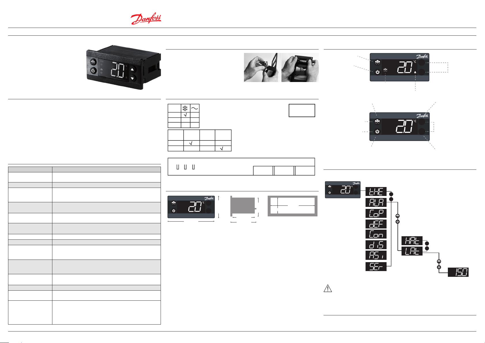
y Insert the ERC 101 in to the cabinet
y Attach the clips to each side of the
ERC 101
Input/output
DO
1(o1)
2
3
Input/
Sensors
Cabinet
Sensors
DO1:
L
UL: 16FLA 72LRA,
N
IEC: 16(16)A
Evapor.
Sensors
Conden.
Sensors
S1
S2
1 2 3
DO & Input/Sensors
Dimensions mm
36.5 mm
^
^
78.25 mm
100-240VAc +/-10% 50/60Hz
OT 55
S1 S2
28 mm
47.25 mm
30 mm
ERC 101
controller
71 mm
rear mounting
Display/operation
Press BRIEFLY to defrost
Press the button
5 seconds to ON/OFF
The green def symbol is list
when in defrost mode
Press: variable direct function defrost
Sub function: BACK
Press: upper left button BACK
to return to parameter group
To select: press the lower
left button (OK)
Press: variable direct functionON/OFF
Sub function: OK
Operation menu
Press 5 sec both right buttons
to access the menu
1) Parameter groups
^
^
^
^
Flasching
Press any button to acknowlege
^
^
^
Scroll through the
^
menu group
Higher left button to exit
Lower left button to conrm
2) Parameter name
Higher left button to exit
Lower left button to conrm
Press UP/DOWN to
adjust setpoint
Press: tempearture setpoint
sub function: UP
Press and hold for 5 seconds
to enter the menu
Press: UP/DOWN to scroll
through the menu
Press: tempearture setpoint
sub function: DOWN
^
Scroll through the
^
parameters group
3) Parameter value
non-condensing
Resistance to heat
& re
EMC category Category I
Operating cycles
Approvals
Produce d by Danfoss A/S (EL-MSSM/AZ ) | March 2014 DKRCC.EI. RL0.A3.02/520H8599 1
Category D (UL94-V0)
Compressor relay:
more than 175,000 at full load ((16A) 16A)
R290/R600a: EN/IEC 60079-15:2005,
Glow wire according to EN/IEC 60335-1,
IEC/EN 60730, UL60730, NSF, CQC, GOST R 60730
Note: These approvals are only valid when using the
accessories listed in this document
IMPORTANT NOTE
The inputs are not galvanic separated and are connected directly to
the mains supply! For that reason, door-switches, sensors as well as the cables must full the reinforced
insulation requirements.
Safety info
Risk of electrocution!
For mounting: do not connect mains power until the controller is correctly mounted.
For unmounting: disconnect the power supply before unmounting
Page 2
MAKING M ODERN LIVING POS SIBLE
EN-Instruction sheet ERC 101 kit
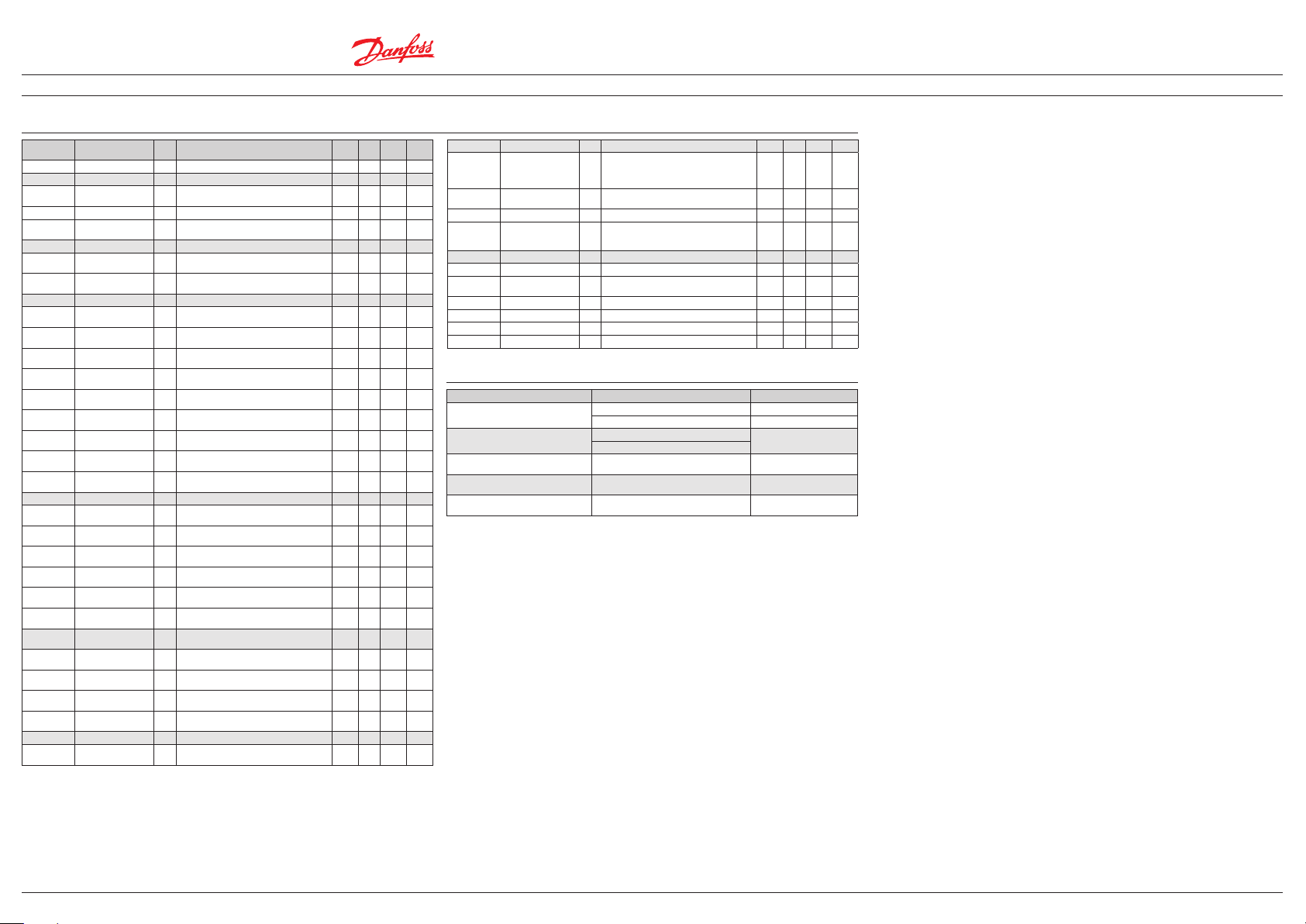
Parameters
Menu Parameters Cod Description Min Max Unit
Thermostat tHE Thermostat settings
Alarm ALA Alarm setting
Compressor CoP Compressor Setting
Defrost dEF Defrost Setting
Condenser
Protection
Display diS Display setting
Setpoint Stp Setpoint -50 80 C 2
Setpoint adjustment
ratio
Dierential diF Thermostat dierential 0.0 20.0 K 2.0
Air temperature
adjust
High temperature
alarm
Low temperature
alarm
Min run time Crt
Min Stop time CSt
Max OFF time Cot
Error run time Ert
Error stop time ESt
Minimum cut-in
voltage
Minimum cut-out
voltage
Maximum voltage uHi
Power ON delay Pod
Defrost type dFt
Terminating temp dtt
Def Min Interval dii
Def Max Interval dAi
Def Min time dit
Def Max time dAt
Condenser Alarm
Limit
Condens er Block
Lim it
Condenser OK limit CoL
Condenser Low Temp CLL
Lock-time After
defrost
SPr Current setpoint adjustment value diF * SPr 0.0 1.0 - 0.0
tAD Air Temp Adjust 0.0 20.0 K 0
Alarm is activated above this temperature
HAt
(Celsius )
Alarm is activated below this temperature
LAt
(Celsius )
Minimum time compressor must run 0-30
minutes
Minimum time compressor must idle 0-30
minutes
Maximum time compressor must idle 0-480
minutes
Compressor run time if temperature sensor is
not working (0-60 minutes )
Compressor stop time if temperature sensor is
not working (0-60 minutes )
When compressor is OFF:
uLi
lowest compressor start voltage (0-270 V)
When compressor is ON:
uLo
lowest operation voltage (0-270 V)
When compressor is ON:
highest operation voltage (0-270 V)
Delay in seconds between power ON &
compressor being activated
No: defrost function is disabled,
nat: OFF-cycle defrost (natural defrost)
Temp at which defrost stop
(evap temperature or cabinet temperature)
The minimum time in hours between the start
of each defrost cycle
The maximum time in hours between the
start of each defrost cycle
The minimum duration of a defrost cycle
in minutes
The maximum duration of a defrost cycle
in minutes
Con Condenser protection settings
If condenser sensor exceeds this temperature,
CAL
alarm is activated
If this temperature is exceeded, compressor
CbL
will be stopped
Temperature at which compressor may start
after a stop due to exceeding CbL
Temperature below which the compressor is
not allowed to start
dLt Display lock time after defrost [0-60 min] 0 60 min 5
-50.0 80.0 C 15.0
-50.0 80.0 C -50.0
0 30 min 0
0 30 min 0
0 480 min 0
0 60 min 0
0 60 min 0
0 270 Vac 0
0 270 Vac 0
0 270 Vac 270
0 300 Sec 180
no nat - nat
0 25 C 7
0 96 hours 6
0 96 hours 7
0 240 min 10
0 480 min 30
0 85 C 75
0 85 C 85
0 85 C 60
-50 20 C -5
Default
Assignments Assignments of inputs and outputs
S2 Application S2A
DO1 conguration o1C
Password level1 PS1 Shop owner Most common parameters 0 999 - 0
Password level2 PS2
Service Service
Voltage value uAC Current main power supply voltage 0 270 Vac -
Relay 1 counter rL1
Interval counter int Compressor run time since last defrost 0 999 min -
Defrost time counter dnt Duration of last defrost cycle [min] 0 999 min -
Firmware version Fi r Danfoss software version number - - - -
Hardware version HAr Danfoss hardware version number - - - -
Application to be controlled with Sensor
C. (nC=Not Connected, Sco= Temp control,
EuA= Evap temp, Con=Cond temp {condenser
cleaning})
Relay output 1. compressor (CoP)
2. Heater HeT
Service technician all parameters with read
permission and possibility to change a
number of parameters
Thousands of cycles of compressor relay since
manufacture
nC Con - nc
CoP HeT - CoP
0 999 - 0
0 999 1000 -
Problem solving
Problem Probable cause Remedy
Compressor does not start
E01 or E02 is shown on display
Display alternates between "Con" and
temperature
Display alternates between "Hi" and
temperature
Display alternates between "Lo" and
temperature
Waiting for compressor delay timer Check CoP->CSt
Line voltage to compressor too low or too high Check CoP->uLi, uLo, uHi
E01: Sensor "S1" defective
E02: Sensor "S2" defective
Condenser temperature exceeds the
temperature set in condenser settings menu
Temperature too high Check ALA->HAt
Temperature too low Check ALA-> LAt
Replace sensor
Clean condenser,
Check Con->CAL, CbL
Danfoss can accept no responsibility for possible errors in catalogues, brochures and other printed material. Danfoss reserves the right to alter its products without notice. This also applies to products already on order provided that such alternations can be made without subsequential changes being necessary in specications already agreed. All trademarks in this material are property of the respecitve companies. Danfoss and Danfoss logotype are trademarks of Danfoss A/S. All rights reserved.
Produce d by Danfoss A/S (EL-MSSM/AZ ) | March 2014 DKRCC.EI. RL0.A3.02/520H8599 2
 Loading...