

Page 1
User Guide
Motor / Generator
EM-PMI540-1500
danfoss.com
Page 2
4
4
4
5
6
6
7
7
8
8
8
9
9
10
12
13
14
15
17
18
19
19
19
20
20
21
24
24
24
26
26
27
28
28
28
29
32
32
32
32
1. General information
1.1. Copyright .........................................................................................................................................................................................
1.2. Intended use of the manual .....................................................................................................................................................
1.3. Product naming convention ....................................................................................................................................................
1.4. Conformity according to standards .......................................................................................................................................
1.5. Warranty ..........................................................................................................................................................................................
1.6. Terms and abbreviations ...........................................................................................................................................................
1.7. Trademarks .....................................................................................................................................................................................
1.8. Responsibility of the manufacturer .......................................................................................................................................
2. Safety information
2.1. General safety statement ..........................................................................................................................................................
2.2. Safety message signal words ...................................................................................................................................................
2.3. Safety symbols ..............................................................................................................................................................................
2.4. Personal protective equipment ..............................................................................................................................................
2.5. Security features ...........................................................................................................................................................................
2.6. Electromagnetic compatibility (EMC) .................................................................................................................................
3. Product overview
3.1. Intended use of the electric machine .................................................................................................................................
3.2. Used technology ........................................................................................................................................................................
3.3. System introduction .................................................................................................................................................................
3.4. Connections and interfaces ...................................................................................................................................................
3.5. Rating plate ..................................................................................................................................................................................
3.6. Tightening torques ....................................................................................................................................................................
4. Design principles
4.1. System design .............................................................................................................................................................................
4.1.1. Cooling and temperature measurement ..................................................................................................................
4.1.2. Inverter ..................................................................................................................................................................................
4.2. Mounting structure ...................................................................................................................................................................
4.2.1. Supporting structure requirements ............................................................................................................................
4.2.2. Shaft alignment and load ...............................................................................................................................................
5. Transportation and storage
5.1. Transportation ............................................................................................................................................................................
5.2. Receiving and unpacking .......................................................................................................................................................
5.3. Lifting .............................................................................................................................................................................................
5.4. Storage ...........................................................................................................................................................................................
5.4.1. Extended storage ..............................................................................................................................................................
6. Installation
6.1. Required tools .............................................................................................................................................................................
6.2. Insulation resistance test .........................................................................................................................................................
6.3. Mechanical installation ............................................................................................................................................................
6.3.1. Allowed mounting positions .........................................................................................................................................
6.3.2. Mounting the electric machine ....................................................................................................................................
6.3.3. Cooling connections ........................................................................................................................................................
6.4. Electrical installation .................................................................................................................................................................
6.4.1. Power connections ...........................................................................................................................................................
6.4.1.1. High voltage connection ........................................................................................................................................
EM-PMI540-T1500
Table of Contents
| BC265856800806en-000106
©
Danfoss | Produced By: Danfoss Power Solutions | January 2019 | 1
Page 3
34
35
40
42
45
46
47
47
48
48
49
50
50
53
57
57
6.4.1.2. Connection diagram ................................................................................................................................................
6.4.1.3. Cable gland assembly and power line connection .......................................................................................
6.4.2. Low voltageconnections ................................................................................................................................................
6.4.3. Grounding connections ..................................................................................................................................................
6.4.4. Anti-condensation heater connections .....................................................................................................................
7. Operation
7.1. Operation conditions ...............................................................................................................................................................
7.2. Condition monitoring during operation ...........................................................................................................................
7.3. Recommended lubricants ......................................................................................................................................................
7.4. Recommended coolants .........................................................................................................................................................
7.5. Emergency operation ...............................................................................................................................................................
8. Maintenance
8.1. Regular maintenance ...............................................................................................................................................................
8.2. Cleaning ........................................................................................................................................................................................
8.3. Bearings and lubrication .........................................................................................................................................................
8.4. Cooling system maintenance ................................................................................................................................................
9. Dismounting
10. Troubleshooting
11. Aftersales
11.1. Service policy ............................................................................................................................................................................
11.2. Service parts ..............................................................................................................................................................................
12. Disposal
13. Storage, installation and maintenance checklists
EM-PMI540-T1500
Table of Contents
2 | ©Danfoss | Produced By: Danfoss Power Solutions | January 2019
| BC265856800806en-000106
Page 4
Revision Information
6
EM-PMI540-T1500
| BC265856800806en-000106
©
Danfoss | Produced By: Danfoss Power Solutions | January 2019 | 3
Page 5
This manual is the installation, operation and maintenance manual for the EM-PMI540-
T1500electric machine.
Copyright
Danfoss Oy. All rights reserved.
No parts of this manual may be reproduced or transmitted in any form or by any means, electrical
or mechanical including photocopying, recording or by an information storage or retrieval system,
without permission in writing from the publisher.
All specications and contents of this manual are subject to change without notice.
Intended use of the manual
This manual contains instructions necessary to safely and properly handle, install, operate and
maintain the electric machine. They should be brought to the attention of anyone who installs,
operates or maintains the machine or associated equipment.
All of the safety warnings and instructions in this book must be followed to prevent injury to
personnel or damage to property . Only qualied and authorized personnel, familiar with health
and safety requirements and national legislation, shall be permitted to handle, install, operate and
maintain the device.
This manual must be kept for future reference during installation, operation and maintenance.
This manual uses illustrations as examples only. Illustrations in this manual may not necessarily
reect all system features.
Product naming convention
In this user guide, EM-PMIfamily permanent magnet motors and generators are referred to as the
electric machine.
Frame model indicates dimensions and electrical characteristics of the electric machine. The
following naming convention is used to refer to the electric machine frame model:
EM-PMI540-T1500-XXXX+XX
Table 1. The namingcodes of the electric machine
Part of
the
name
Meaning
EM Electric Machine
PMIXXX
or
PMEXXX
Permanent Magnet Internal and a number relative to thediameterof the electric machine, or
Permanent Magnet External and a number relative todiameter of the electric machine
TXXXX Average continuous torque of the motor range, relative to the lenght of the machine
XXXX Rated rotation speed
+XX Options, see option tablebelow.
The power input of the machine may require one or several three phase power systems. This is
indicated by a power connection option marking, for example:DUAL or QUAD in the machine
model code. One three phases power system can include one or three connection boxes in the
machine. The most usual case is when an electric machine has a single connection box, but this is
not shown in the machine modelcode.
Example: EM-PMI540-T1500-1200-DUAL
EM-PMI540-T1500
1. General information
4 | ©Danfoss | Produced By: Danfoss Power Solutions | January 2019
| BC265856800806en-000106
Page 6
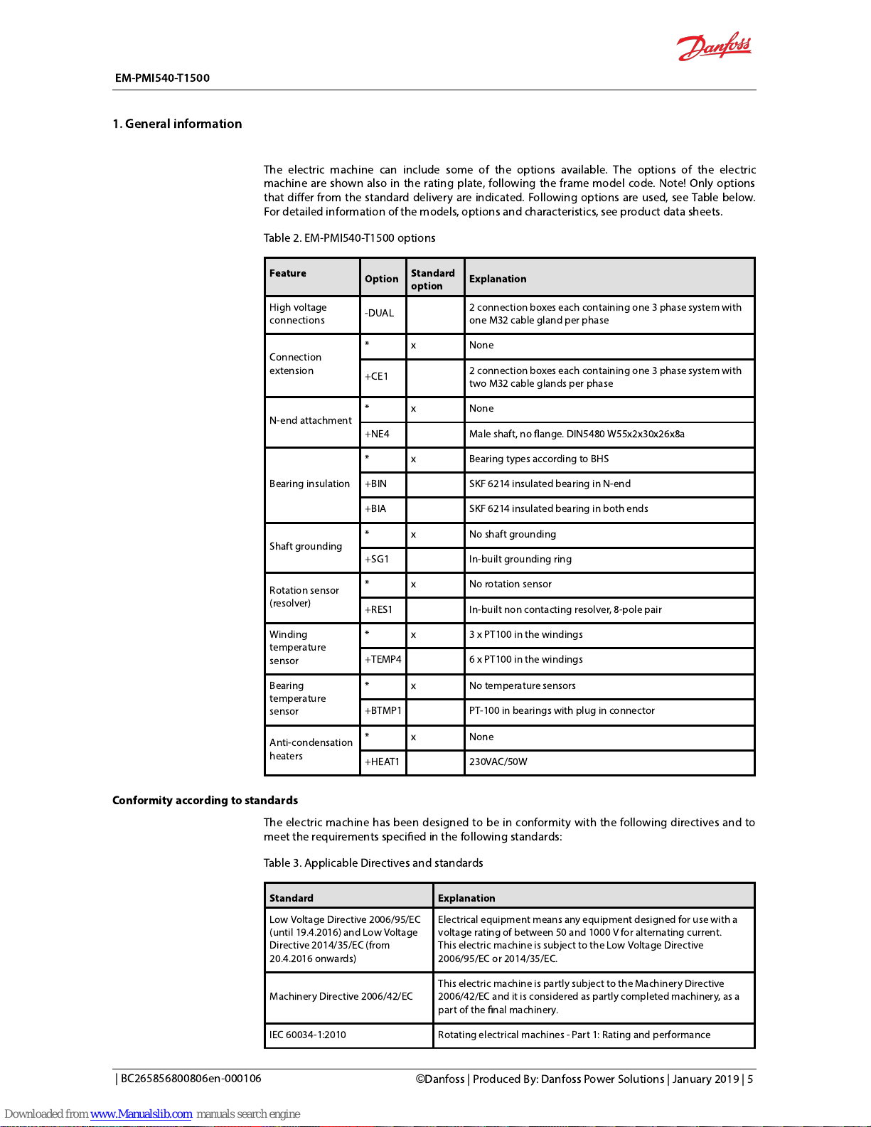
The electric machine can include some of the options available. The options of the electric
machine are shown alsoin the rating plate, following the frame model code. Note! Only options
that differ from the standard delivery are indicated. Following options are used, see Tablebelow.
For detailed information of the models, options and characteristics, see product data sheets.
Table 2. EM-PMI540-T1500 options
Feature
Option
Standard
option
Explanation
High voltage
connections
-DUAL
2 connection boxes each containing one 3 phase system with
one M32 cable gland per phase
Connection
extension
* x None
+CE1
2 connection boxes each containing one 3 phase system with
two M32 cable glands per phase
N-end attachment
* x None
+NE4 Male shaft, no ange. DIN5480 W55x2x30x26x8a
Bearing insulation
* x Bearing types according to BHS
+BIN SKF 6214 insulated bearing in N-end
+BIA SKF 6214 insulated bearing in both ends
Shaft grounding
* x No shaft grounding
+SG1 In-built grounding ring
Rotation sensor
(resolver)
* x No rotation sensor
+RES1 In-built non contacting resolver, 8-pole pair
Winding
temperature
sensor
* x 3 x PT100 in the windings
+TEMP4 6 xPT100 in the windings
Bearing
temperature
sensor
* x No temperature sensors
+BTMP1 PT-100 in bearings with plug in connector
Anti-condensation
heaters
* x None
+HEAT1 230VAC/50W
Conformity according to standards
The electric machinehas beendesigned to be in conformity with thefollowing directives and to
meet the requirements specied in the following standards:
Table 3. Applicable Directives and standards
Standard Explanation
Low Voltage Directive 2006/95/EC
(until 19.4.2016) andLow Voltage
Directive 2014/35/EC (from
20.4.2016 onwards)
Electrical equipment means any equipment designed for use with a
voltage rating of between 50 and 1000 V for alternating current.
Thiselectric machineissubject to the Low Voltage Directive
2006/95/EC or 2014/35/EC.
Machinery Directive 2006/42/EC
This electric machine is partly subject to the Machinery Directive
2006/42/EC and it is considered as partly completed machinery, as a
part of the nal machinery.
IEC 60034-1:2010 Rotating electrical machines - Part 1: Rating and performance
EM-PMI540-T1500
1. General information
| BC265856800806en-000106
©
Danfoss | Produced By: Danfoss Power Solutions | January 2019 | 5
Page 7
IEC 60034-5:2001/A1:2007
Rotating electrical machines - Part 5: Degrees of protection provided
by the integral design of rotating electrical machines (IP code) -
Classication
IEC 60034-6:1993 Rotating electrical machines - Part 6: Methods of cooling
IEC 60034-7:1993
Rotating electrical machines - Part 7: Classication of types of
construction, mounting arrangements and connection box position
(IM Code)
IEC 60034-8:2007/A1:2014
Rotating electrical machines - Part 8: Terminal markings and direction
of rotation
IEC 60034-14:2004/A1:2007
Amendment 1 - Rotating electrical machines - Part 14: Mechanical
vibration of certain machines with shaft heights 56 mm and higher -
Measurement, evaluation and limits of vibration severity.
Warranty
Danfoss offers warranty against defects in workmanship and materials for its products for a period
of twelve (12) months from commissioning or eighteen months (18) from delivery (Incoterms-
EXW), whichever occurs rst.
In order for the warranty to be valid, the customer must follow the requirements of this and all
related documents, especially those set out in the product installation and maintenance, as well as
the applicable standards and regulations in force in each country.
Defects arising from the improper or negligent use, operation, and/or installation of the
equipment, non-execution of regular preventive maintenance, as well as defects resulting from
external factors or equipment and components not supplied/recommended by Danfoss, will not
be covered by the warranty.
The warranty will not apply if the customer at its own discretion makes repairs and/or
modications to the equipment without prior written consent from Danfoss.
Terms and abbreviations
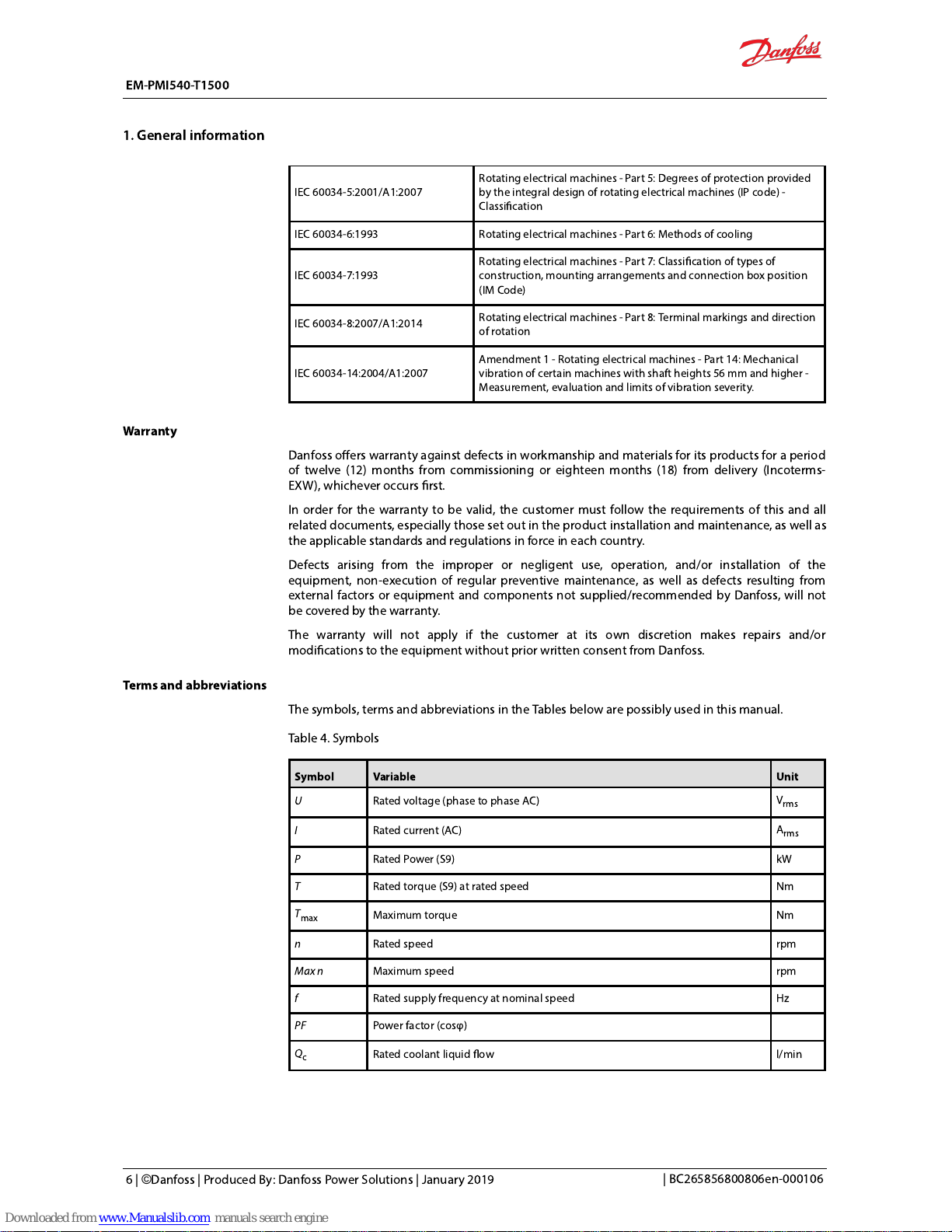
Thesymbols, terms and abbreviations in the Tables below are possibly used in this manual.
Table 4. Symbols
Symbol Variable Unit
U
Rated voltage (phase to phase AC)
V
rms
I
Rated current (AC)
A
rms
P
Rated Power (S9) kW
T
Rated torque (S9) at rated speed Nm
T
max
Maximum torque Nm
n
Rated speed rpm
Max n
Maximum speed rpm
f
Rated supply frequency at nominal speed Hz
PF
Power factor (cosφ)
Qc
Rated coolant liquid ow l/min
EM-PMI540-T1500
1. General information
6 | ©Danfoss | Produced By: Danfoss Power Solutions | January 2019
| BC265856800806en-000106
Page 8
Tc
Rated coolant liquid input temperature °C
T
amb
Rated ambient temperature °C
RES_COS
Cosine signal received from the resolver deg
RES_SIN
Sinusoidal signal received from the machine resolver deg
GND
Ground in electrical connections
Ω
(Ohm)
Resistance
Ω
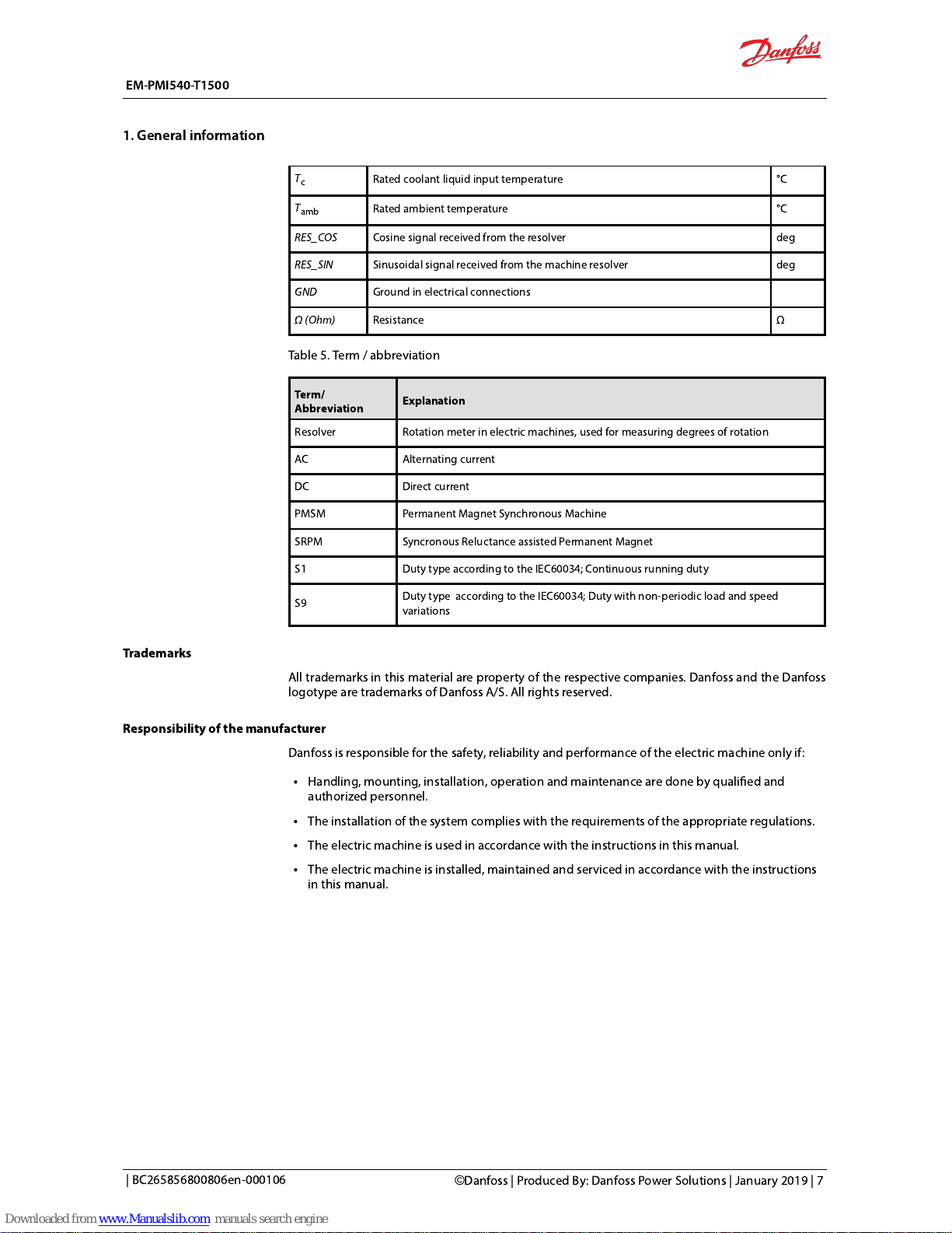
Table 5. Term / abbreviation
Term/
Abbreviation
Explanation
Resolver Rotation meter in electric machines, used for measuring degrees of rotation
AC Alternating current
DC Direct current
PMSM Permanent Magnet Synchronous Machine
SRPM Syncronous Reluctance assisted Permanent Magnet
S1 Duty type according to the IEC60034;Continuous running duty
S9
Duty type according to the IEC60034; Duty with non-periodic load and speed
variations
Trademarks
All trademarks in this material are property of the respective companies. Danfoss and the Danfoss
logotype are trademarks of Danfoss A/S. All rights reserved.
Responsibility of the manufacturer
Danfossis responsible for the safety, reliability and performance of the electric machineonly if:
Handling, mounting, installation, operation and maintenance are done by qualied and
authorizedpersonnel.
The installation of the system complies with the requirements of the appropriate regulations.
The electric machineis used in accordance with the instructions in this manual.
The electric machineis installed, maintained and serviced in accordance with the instructions
in this manual.
EM-PMI540-T1500
1. General information
| BC265856800806en-000106
©
Danfoss | Produced By: Danfoss Power Solutions | January 2019 | 7
Page 9
General safety statement
The electric machineis intended for use as a component for industrial and commercial
installations. The end product containing the electric machinemust conform with all related
regulations.
The use of the electric machineis prohibited in hazardous areas unless it is expressly designed
for such use.
The electric machineis intended for installation, use and maintenance by qualied personnel,
familiar with health and safety requirements and national legislation. Ignoring these
instructions may invalidate all applicable warranties.
These instructions must be followed to make sure of safe and correctinstallation, operation
and maintenance of the electric machine. They should be brought to the attention of anyone
who installs, operates or maintains the electric machineor associated equipment.
High voltage and rotating parts can cause serious or fatal injuries. For electric machinecovered
by this manual, it is important to observe safety precautions to protect personnel from
possible injury.
Safety message signal words
Safety message signal words indicate the severity of a potential hazard.
DANGER
Indicates an imminently hazardous situation which, if not avoided, will result in death or
serious injury.
WARNING
Indicates a potentially hazardous situation which, if not avoided, could result in death
or serious injury.
CAUTION
Indicates a potentially hazardous situation which, if not avoided, may result in minor or
moderate injury. CAUTION may also alert against unsafe practices.
NOTICE
Indicates a potentially hazardous situation which, if not avoided, could result in property
damage.
Safety symbols
The following safety- and information related symbols appear in this manual and on the electric
machine.
Danger
This symbol is is identied by a yellow background, red octagonal band and a black STOP text. It indicates a hazardous situation
that causes severe injury or death. Action indicated by this symbol may not be executed.
General warning
This symbol is identied by a yellow background, black triangular band, and a black exclamation point symbol. It indicates a
general potentially hazardous situation.
Electric shock warning
The symbol is identied by a yellow background, black triangular band, and a black arrowhead symbol. It indicates dangerous
electrical voltage that could cause an electric shock to a person.
Burn warning
The symbol is identied by a yellow background, black triangular band, and a black wavy lines- symbol. It indicates a hot device
that could cause burns to a person.
Magnet warning
The symbol is identied by a yellow background, black triangular band, and a black magnet symbol. It indicates strong magnetic
eld that could cause harm to a person or property.
EM-PMI540-T1500
2. Safety information
8 | ©Danfoss | Produced By: Danfoss Power Solutions | January 2019
| BC265856800806en-000106
Page 10
Rotating shaft warning
The symbol is identied by a yellow background, black triangular band, and a black rotating shaft symbol. It indicates strong
rotating shaft that could cause harm to a person or property.
General Information
Read the instructions in the manual
Personal protective equipment
Personal protective equipment shall be used when necessary during handling, installation and
maintenance of the electric machine to avoid injury.
Use eye protective equipment like safety goggles or mask when you workwith the electric device.Permanent damage to the eye
could be caused if bearing grease, melted nitrile rubber (radial lip seal), glycol or other uids splash.
Use hearing protective equipment when you workon the electric machine.Hearing injuries canbe caused by too loud noise
(noise in excess of 85 dBA).
Use head protective equipment like helmet when you liftthe electric machine! Head injuries canbe caused by object impact.
Use cut resistant gloves when youhandleand maintainthe electric machine.There is a risk of cut injuries.
Use protective footwear when you liftor movethe electric machine! Foot injuries could be caused if lifting system or lifting
brackets fail.
Security features
The electric machinehasat least one PT100 temperature sensor in the windings. The amount of
the sensors depend on the options chosen. The temperature signal(s) can be read out from the
measurement connector of the machine. You can connect the temperature signal to the
temperature surveillance pin in the inverter (EC-C) and make sure that the inverter has the
machine temperature protection feature activated.
Theelectric machinecan be ordered with bearing temperature measurement. This option includes
one PT100 temperature sensor at both D-end and N-end bearings. The signal can be read out
using a separate connector at both ends.
The electric machine hasleakage sensors (2pcs) at the lower part of the electric machine. This
feature is usefulin moist conditions to detect possible excessive water in contact with the electric
machine. Separate connectors for both leakage signals exist.
EM-PMI540-T1500
2. Safety information
| BC265856800806en-000106
©
Danfoss | Produced By: Danfoss Power Solutions | January 2019 | 9
Page 11
Electromagnetic compatibility (EMC)
When interfacing other equipment, connect only equipment that are specied as part of the system and that
arecompatible.
Magnetic and electromagnetic elds generated near the current-carrying conductors and permanent magnets in electric
machines represent a health danger to persons with heart pacemakers, metal implants and hearing aids. Persons with a
heart pacemaker, metal implants or hearing aids must consult a doctor before they enter the following areas:
Areas in which electric equipment and parts are operated
Areas in which electric equipment with permanent magnets are stored, mounted, operated or repaired
If necessary, perform a special electromagnetic compatibility (EMC) test on the installation
.
EMC stands for Electromagnetic compatibility. It is the ability of electric equipment to operate
without problems within an electromagnetic environment. Likewise, the equipment must not
disturb or interfere with any other product or system within its locality. This is a legal requirement
for all equipment taken into service within the European Economic Area (EEA).
Our products are designed with high standards of EMC in mind. Connect the power lines and
groundings along the instructions in this manual to achieve the required level of EMIprotection.
It is the responsibility of the installer to ensure that the equipment or system into which the
product is incorporated complies with the EMC legislation of the country of use. Within the
European Union, equipment into which this product is incorporated must comply with the EMC
Directive 2004/108/EC.
EM-PMI540-T1500
2. Safety information
10 | ©Danfoss | Produced By: Danfoss Power Solutions | January 2019
| BC265856800806en-000106
Page 12
Theelectric machineshavebeen developed especially for heavy duty, marine and transportation
applications. They aremore reliable, smaller, lighter and moreefficientthan conventional products
on the market.
Typical applications ofthe electric machines are:
Motor (electric propulsion) and generator for hybrid marine vessels or mobile work machine
and bus parallel hybrid applications.
Traction motor and generator for electrical or hybrid electrical mobile work machines or buses.
The electric machines feature Syncronous Reluctance assisted Permanent Magnet (SRPM) motor
technology, having several advanced features:
Extremely compact and robust structure.
High efficiency throughout the operation range.
Liquid cooling with water/glycol mixture.
Low coolant ow required.
High allowed coolant temperature.
IP65 enclosure class to maximize reliability.
Multiple mounting possibilities.
Extended speed and torque capabilities compared to standard PM machines.
Machine structure designed to be able to produce high starting torques (instant torque to
non-moving wheel).
Optimized speed range to meet most common gear ratios used in heavy mobile machinery.
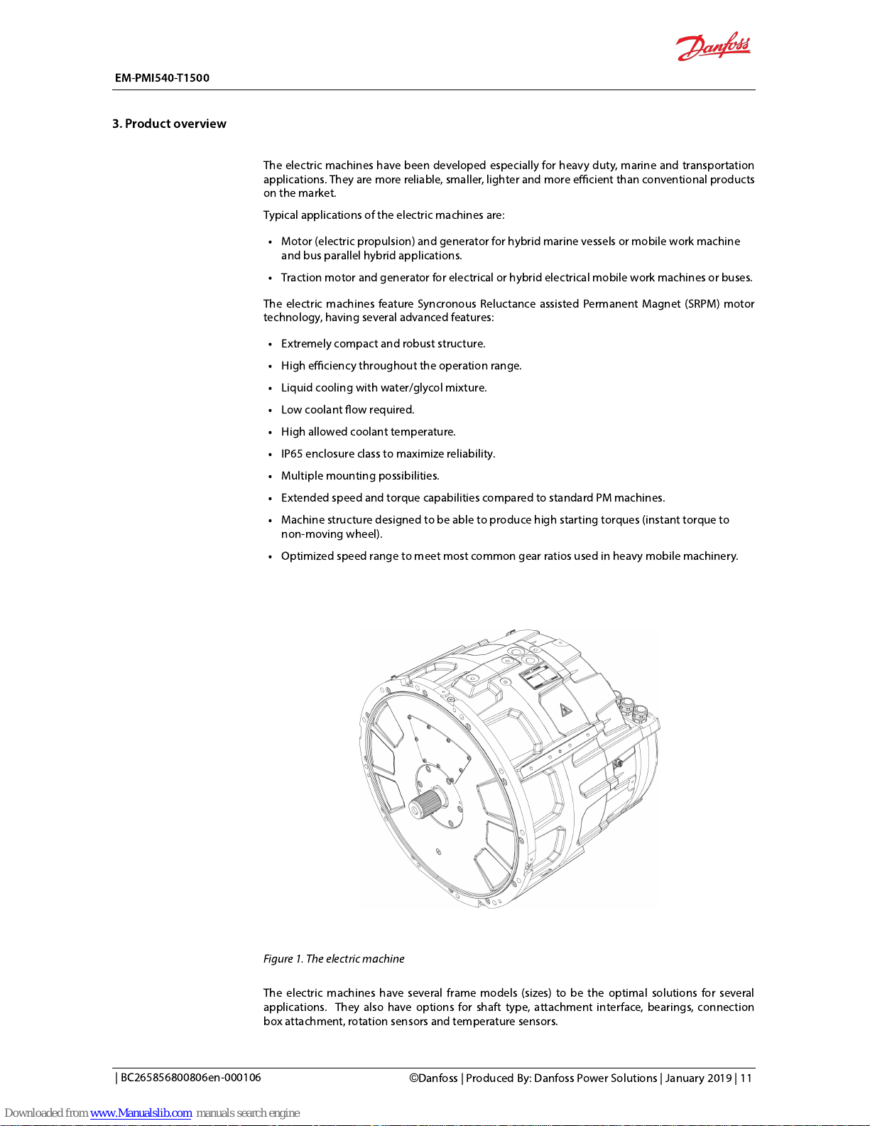
Figure 1. The electric machine
Theelectric machines have several frame models (sizes) to be the optimal solutions for several
applications. Theyalso haveoptions for shaft type, attachment interface, bearings, connection
box attachment, rotation sensors and temperature sensors.
EM-PMI540-T1500
3. Product overview
| BC265856800806en-000106
©
Danfoss | Produced By: Danfoss Power Solutions | January 2019 | 11
Page 13
Intended use of the electric machine
This electric machineisintended to be used as a motor or generator and as a part of a machinery,
for examplein:
Power train of a marine vessel, transportation vehicle or a heavy duty work machine.
Power generation equipment.
Theelectric machineisintended to be powered and controlled with an inverter or inverters
capable of supplying three-phase alternating current and that is capable of controlling the
electricmachine. The electric machineisnot suitable for direct online use.
In a power generation equipment theelectric machines are intended to be powered by a prime
mover, for example,an internal combustion engine and controlled by the above mentioned
electric power inverter.
The electricmachineissolely intended for professional use, and may be operated only by trained
professionals. The maintenance of the electric machine may be doneonly by trained professionals.
Not-allowed use of theelectric machine
It is forbidden to use, handle and maintain the machine in following ways (including but not
limited to):
Using the electric machinefor other purposes than dened in thismanual.
Disregarding the obligation to comply with the manual, safety signs and rating plate of the
electric machine.
Using the electric machine, making adjustments and maintenance without rst reading
thismanual.
Exceeding the designed limits during the electric machine operation.
Using non-original service parts of wrong material causing corrosion problems and mechanical
failures in time.
Operating and performing maintenance for the electric machinewithout appropriate personal
protective equipment.
Using electric machine parts like frame, shaft end or terminal box for climbing or for support
for other structures.
Causing any kind of impact forces to the electric machine (for examplehitting or hammering
or dropping objects).
Operating the electric machinewith electric connections other than dened in the manual
and/or other documents.
Operating the electric machinewith insufficiently tightened connections or cable glands.
Operating the electric machinewith power cables routed against the instructions.
Operating the electric machinewithout properly dimensioned and operating cooling system.
Operating theelectric machinewithout following the bearing lubrication instructions.
Accessing the connection box(es) of the electric machine, doingmaintenance or adjustment
operations on the electric machine withthe electricity connected.
Accessing the connection box(es) ifthe shaft canbe turned by an external prime mover.
Lifting the electric machinefrom wrong lifting points and without correctlifting equipment.
EM-PMI540-T1500
3. Product overview
12 | ©Danfoss | Produced By: Danfoss Power Solutions | January 2019
| BC265856800806en-000106
Page 14
Lifting additional load with the machine.
Storing the electric machineoutdoors in wet or dusty conditions.
Storing the electric machinewithout correctsupport to prevent rolling or falling of the
machines.
Using the electric machinein potentially explosive environment.
Allowing dirt or liquid to enter into the electric machine or connection box.
Using cables that can't withstand the maximum currents of the electric machine.
Used technology
The electric machineis aSyncronous Reluctance assisted Permanent Magnet (SRPM) machine. This
technology has several benets compared to standard permanent magnet (PM) technology and
traditional induction machine (IM) technology. The SRPM technology combines the benets of PM
and Syncronous Reluctance technology, having increased torque capability over wide speed range
and ability to produce torque to higher speeds. The electric machine efficiency at lower speeds is
also good.
The supply current to the machine stator windings create rotating magnetic eld, which in turn
rotates the rotor containing permanent magnets. In the syncronous permanent magnet machine,
the rotation of the rotor (shaft) is syncronized with the frequency of the power supply current. The
reluctance technology maximizes the pull-out torque of the machine.
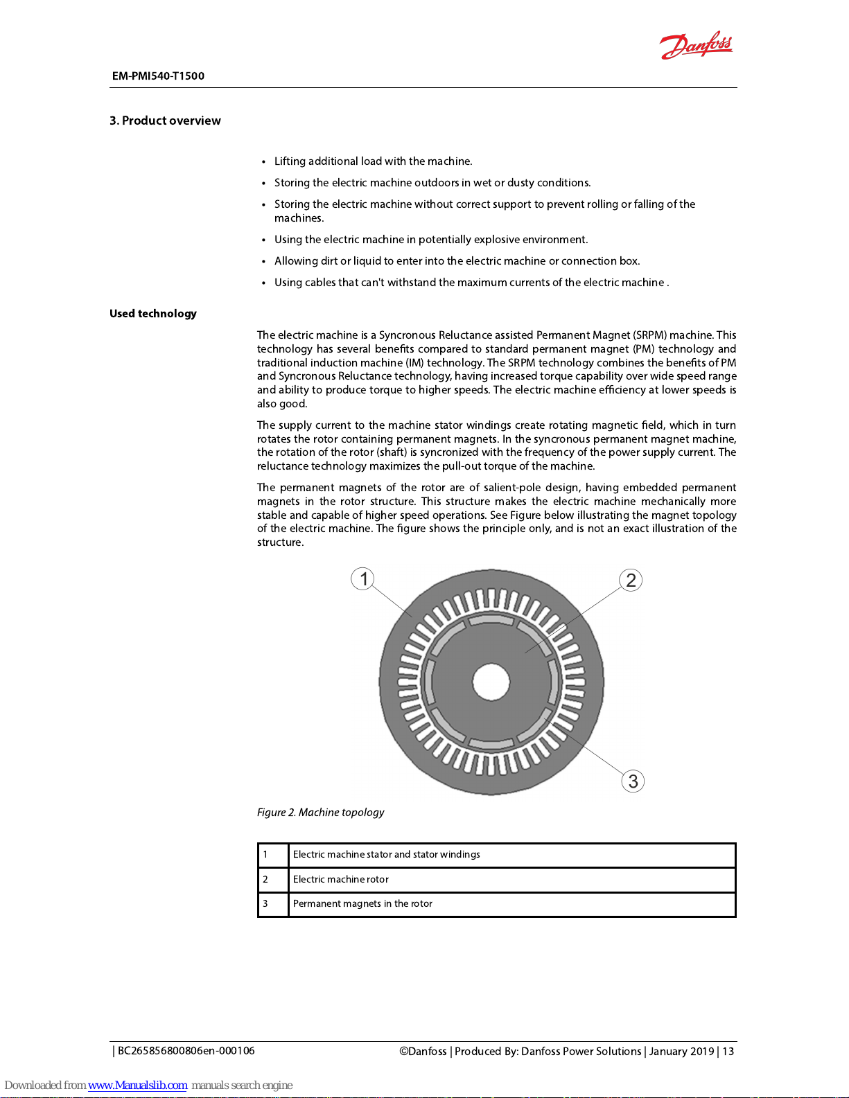
The permanent magnets ofthe rotor are of salient-pole design, having embedded permanent
magnets in the rotor structure. This structure makes theelectric machine mechanically more
stable and capable of higher speed operations. See Figure below illustrating the magnet topology
of the electric machine. The gure shows the principle only, and is not an exact illustration of the
structure.
Figure 2. Machinetopology
1 Electric machine stator and stator windings
2 Electric machine rotor
3 Permanent magnets in the rotor
EM-PMI540-T1500
3. Product overview
| BC265856800806en-000106
©
Danfoss | Produced By: Danfoss Power Solutions | January 2019 | 13
Page 15
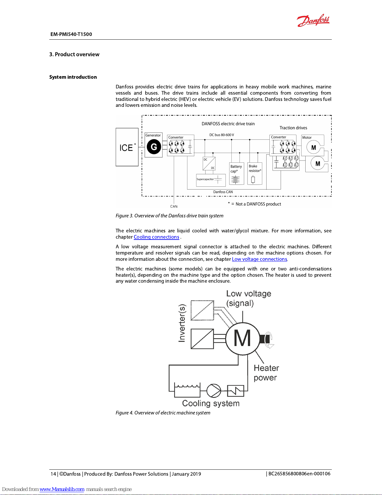
System introduction
Danfoss provides electric drive trains for applications in heavy mobile work machines, marine
vessels and buses. The drive trains include all essential components from converting from
traditional to hybrid electric (HEV) or electric vehicle (EV) solutions. Danfosstechnology saves fuel
and lowers emission and noise levels.
Figure 3. Overview of the Danfoss drive train system
The electric machines are liquid cooled with water/glycol mixture. For more information, see
chapterCooling connections.
A low voltage measurement signal connector is attached to the electric machines. Different
temperature and resolver signals can be read, depending on the machine options chosen. For
more information about the connection, see chapterLow voltageconnections
.
Theelectric machines (some models) can be equipped with one or two anti-condensations
heater(s), depending on the machine type and the option chosen. The heater is used to prevent
any water condensing inside the machine enclosure.
Figure 4. Overview of electric machine system
EM-PMI540-T1500
3. Product overview
14 | ©Danfoss | Produced By: Danfoss Power Solutions | January 2019
| BC265856800806en-000106
Page 16
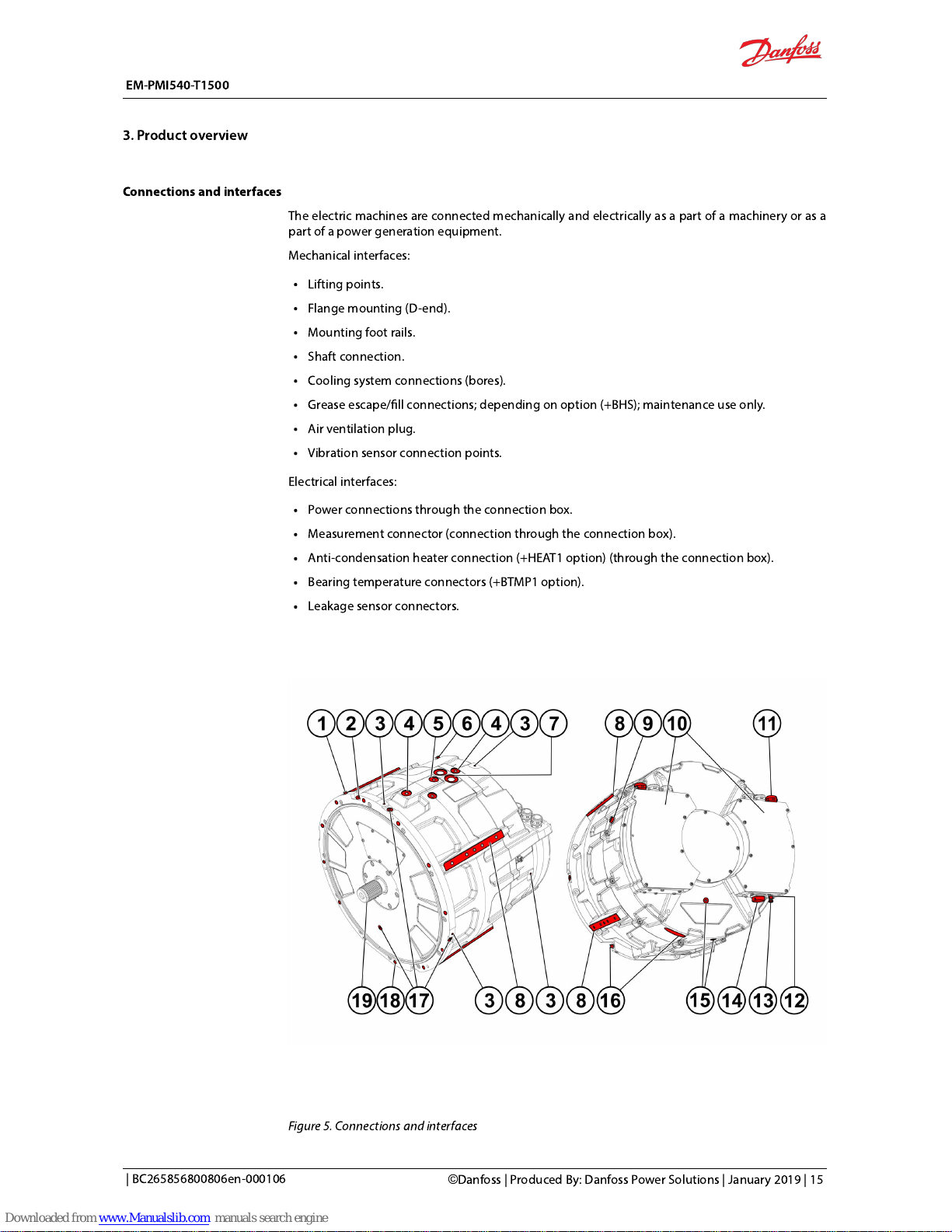
Connections and interfaces
The electric machines are connected mechanically and electrically as a part of a machinery or as a
part of a power generation equipment.
Mechanical interfaces:
Lifting points.
Flange mounting (D-end).
Mounting foot rails.
Shaft connection.
Cooling system connections (bores).
Grease escape/ll connections; depending on option (+BHS); maintenance use only.
Air ventilation plug.
Vibration sensor connection points.
Electrical interfaces:
Power connections through the connection box.
Measurement connector (connection through the connection box).
Anti-condensation heater connection (+HEAT1 option) (through the connection box).
Bearing temperature connectors (+BTMP1 option).
Leakage sensor connectors.
Figure 5. Connections and interfaces
EM-PMI540-T1500
3. Product overview
| BC265856800806en-000106
©
Danfoss | Produced By: Danfoss Power Solutions | January 2019 | 15
Page 17
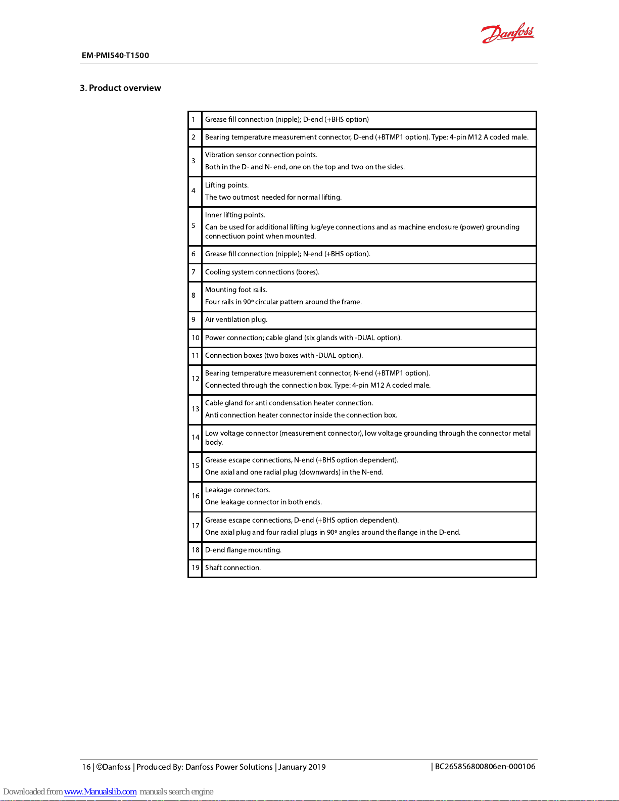
1 Grease ll connection (nipple); D-end (+BHS option)
2 Bearing temperature measurement connector, D-end (+BTMP1 option).Type:4-pin M12 A coded male.
3
Vibration sensor connection points.
Both in the D- and N- end, one on the top and two on the sides.
4
Lifting points.
The two outmost needed for normal lifting.
5
Inner lifting points.
Can be used for additional lifting lug/eye connections and as machine enclosure (power) grounding
connectiuon point when mounted.
6 Grease ll connection (nipple); N-end (+BHS option).
7 Cooling system connections (bores).
8
Mounting foot rails.
Four rails in 90º circular pattern around the frame.
9 Air ventilation plug.
10 Power connection; cable gland (six glands with -DUAL option).
11 Connection boxes (two boxes with -DUAL option).
12
Bearing temperature measurement connector, N-end (+BTMP1 option).
Connected through the connection box.Type:4-pin M12 A coded male.
13
Cable gland for anti condensation heater connection.
Anti connection heater connector inside the connection box.
14
Low voltage connector (measurement connector), low voltage grounding through the connector metal
body.
15
Grease escape connections, N-end (+BHS option dependent).
One axial and one radial plug (downwards) in the N-end.
16
Leakage connectors.
One leakage connector in both ends.
17
Grease escape connections, D-end (+BHS option dependent).
One axial plug and four radial plugs in 90º angles around the ange in the D-end.
18 D-end ange mounting.
19 Shaft connection.
EM-PMI540-T1500
3. Product overview
16 | ©Danfoss | Produced By: Danfoss Power Solutions | January 2019
| BC265856800806en-000106
Page 18
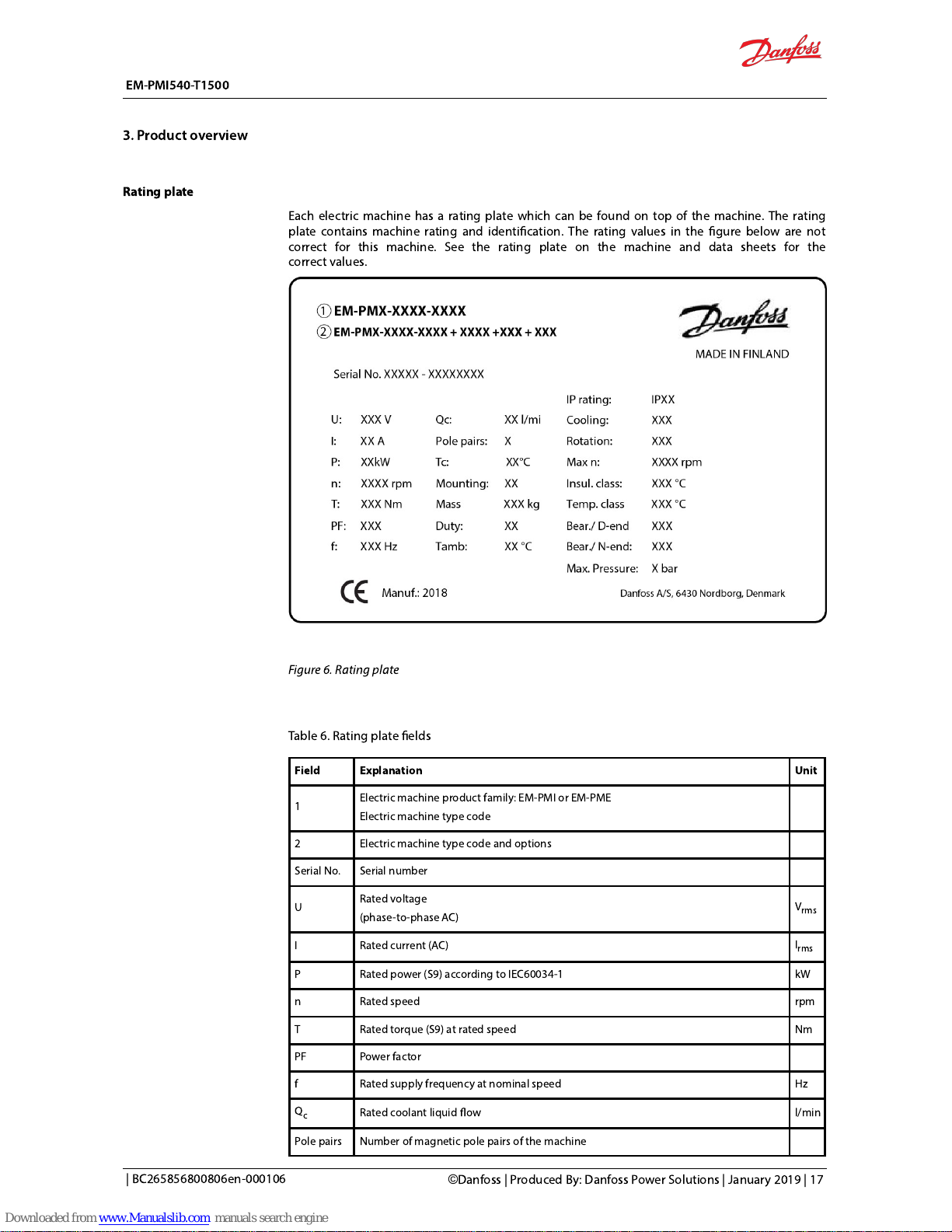
Rating plate
Each electric machine has a rating plate which can be found on top of the machine. The rating
plate contains machine rating and identication. The rating values in the gure below are not
correct for this machine. See the rating plate on the machine and data sheets for the
correctvalues.
Figure 6. Rating plate
Table 6. Rating plate elds
Field Explanation Unit
1
Electric machine product family: EM-PMI or EM-PME
Electric machine type code
2 Electric machine type code and options
Serial No. Serial number
U
Rated voltage
(phase-to-phase AC)
V
rms
I Rated current (AC)
I
rms
P Rated power (S9) according to IEC60034-1 kW
n Rated speed rpm
T Rated torque (S9) at rated speed Nm
PF Power factor
f Rated supply frequency at nominal speed Hz
Qc
Rated coolant liquid ow l/min
Pole pairs Number of magnetic pole pairs of the machine
EM-PMI540-T1500
3. Product overview
| BC265856800806en-000106
©
Danfoss | Produced By: Danfoss Power Solutions | January 2019 | 17
Page 19
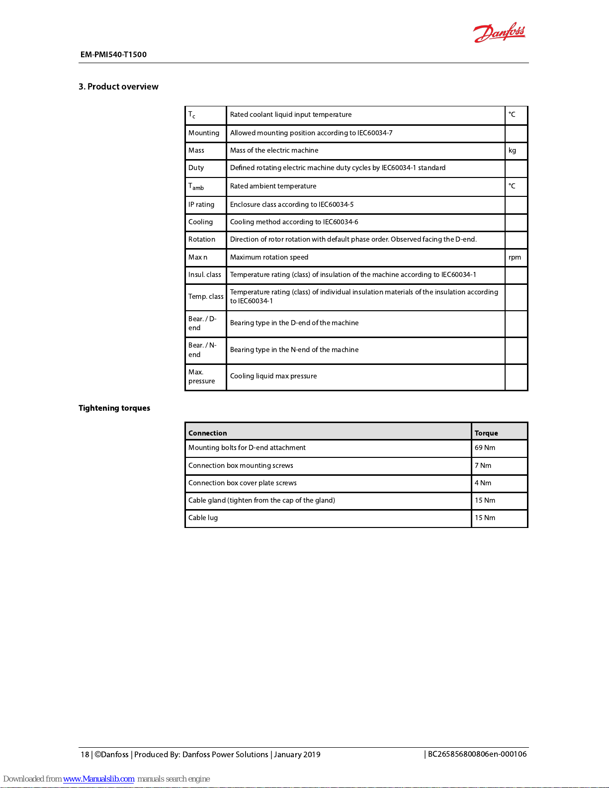
Tc
Rated coolant liquid input temperature °C
Mounting Allowed mounting position according to IEC60034-7
Mass Mass of the electric machine kg
Duty Dened rotating electric machine duty cycles by IEC60034-1 standard
T
amb
Rated ambient temperature °C
IP rating Enclosure class according to IEC60034-5
Cooling Cooling method according to IEC60034-6
Rotation Direction of rotorrotation with default phase order. Observed facing the D-end.
Max n Maximum rotation speed rpm
Insul. class Temperature rating (class) of insulation of the machine according to IEC60034-1
Temp. class
Temperature rating (class) of individual insulation materials of the insulation according
to IEC60034-1
Bear. / D-
end
Bearing type in the D-end of the machine
Bear. / N-
end
Bearing type in the N-end of the machine
Max.
pressure
Cooling liquid max pressure
Tightening torques
Connection Torque
Mounting bolts for D-end attachment 69 Nm
Connection box mounting screws 7 Nm
Connection box cover plate screws 4 Nm
Cable gland (tighten from the cap of the gland) 15 Nm
Cable lug 15Nm
EM-PMI540-T1500
3. Product overview
18 | ©Danfoss | Produced By: Danfoss Power Solutions | January 2019
| BC265856800806en-000106
Page 20
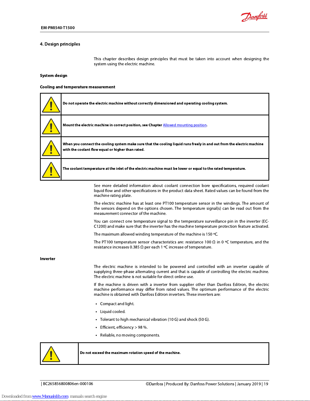
This chapter describes design principles that must be taken into account when designing the
system using theelectric machine.
System design
Cooling and temperature measurement
Do not operate the electric machine without correctlydimensioned and operating cooling system.
Mount the electric machine in correct position, see ChapterAllowed mounting position
.
When you connectthe cooling system make surethat the cooling liquid runs freely in and out from the electric machine
with the coolant ow equal or higher than rated.
The coolant temperature at the inlet of the electric machine must be lower or equal to the rated temperature.
See more detailed information about coolant connection bore specications, required coolant
liquid ow and other specications in the product data sheet. Rated values can be found from the
machine rating plate.
The electric machinehasat least one PT100 temperature sensor in the windings. The amount of
the sensors depend on the options chosen. The temperature signal(s) can be read out from the
measurement connector of the machine.
You can connect one temperature signal to the temperature surveillance pin in the inverter (EC-
C1200) and make sure that the inverter has the machine temperature protection feature activated.
The maximum allowed winding temperature of the machine is 150 ºC.
The PT100 temperature sensor characteristics are: resistance 100 Ω in 0 ºC temperature, and the
resistance increases 0.385 Ω per each 1 ºC increase of temperature.
Inverter
The electric machineisintended to be powered and controlled with an inverter capable of
supplying three-phase alternating current and that is capable of controlling the electricmachine.
The electric machineis not suitable for direct online use.
If the machine is driven with a inverter fromsupplier other than Danfoss Editron, the electric
machine performance may differ from rated values. The optimum performance of the electric
machine is obtained with Danfoss Editroninverters. These inverters are:
Compact and light.
Liquid cooled.
Tolerant to high mechanical vibration (10 G) and shock (50 G).
Efficient, efficiency > 98 %.
Reliable, no moving components.
Do not exceed the maximum rotation speed of the machine.
EM-PMI540-T1500
4. Design principles
| BC265856800806en-000106
©
Danfoss | Produced By: Danfoss Power Solutions | January 2019 | 19
Page 21

Figure 7. EC-C1200
Figure 8. Schematic of the inverter powerstage
The main machine power driving parameters are shown in the machine rating plate. For
moreinformation, please contact Danfossrepresentative.
You can connect one of the temperature signals (from the low voltage connector) to the
temperature surveillance pin in the inverterand make sure that the inverter has the machine
temperature protection feature activated.
Mounting structure
Supporting structure requirements
Do not install the electric machine near or in direct contact with easily ammable materials. The surface of the electric
machine can be hot.
The mating housing arrangement of the electric machine must be secure and sufficiently rigid to
prevent vibrations and mechanical failures. Necessary actions should be taken to avoid corrosion
on the mating housing arrangement.
EM-PMI540-T1500
4. Design principles
20 | ©Danfoss | Produced By: Danfoss Power Solutions | January 2019
| BC265856800806en-000106
Page 22

The supporting structure for the electric machine must be such that the machine can be mounted
using its allowed mounting positions, see chapterAllowed mounting positions.
Themounting space must be adequate for the machine mounting and possible auxiliary
components. See the length and the diameter data of the electric machine from the product
drawing. Main dimensions of the electric machine are shownin the Figure below(not an exact
illustration of the electric machine).
The electric machine has a SAE 1/2 D-end ange (IM 3001). A SAE 1/2 ywheel housing is required
as mating ange. The connection boxes are connected to N-end.
Figure 9. Main dimensions of the machine
Symbol Explanation
L
F
Length of the machine frame (including the connection box(es).
L
S
Length of the shaft (from the end of the shaft to the machine D-end mounting shoulder).
D
M
Diameter of the ange mounting bore circle.
D
S
Diameter of the mounting shoulder.
For all dimensions of the electric machine, see the product drawings.
Shaft alignment and load
Improper alignment (misalignment) may result in bearing overloads, premature bearing failures, vibrations and shaft
failures. Flexible coupling doesnot compensate for excessive misalignment.
The type of the electricmachine shaft is cylindrical shaft with diameter of 70 mm h7 and contact
length of 130 mm. The ange type is SAE 1/2 Transmission housing.
Alignment between the shaft and mating structure must be accurate.
The misalignment can be parallel or angular misalignment, or combination of those. With parallel
misalignment, the center lines of both shafts are parallel but they are offset. With angular
misalignment, the shafts are at an angle to each other. Figures below illustrate the parallel and
angular misalignment.
EM-PMI540-T1500
4. Design principles
| BC265856800806en-000106
©
Danfoss | Produced By: Danfoss Power Solutions | January 2019 | 21
Page 23

Figure 10. Parallel alignment of the shaft and mating structure
Figure 11. Angular alignment of the shaft and mating structure
The maximum external force directed to the shaft axially and radially may not exceed machine specic values.Calculate
these values with the documentDOC-000454.
EM-PMI540-T1500
4. Design principles
22 | ©Danfoss | Produced By: Danfoss Power Solutions | January 2019
| BC265856800806en-000106
Page 24
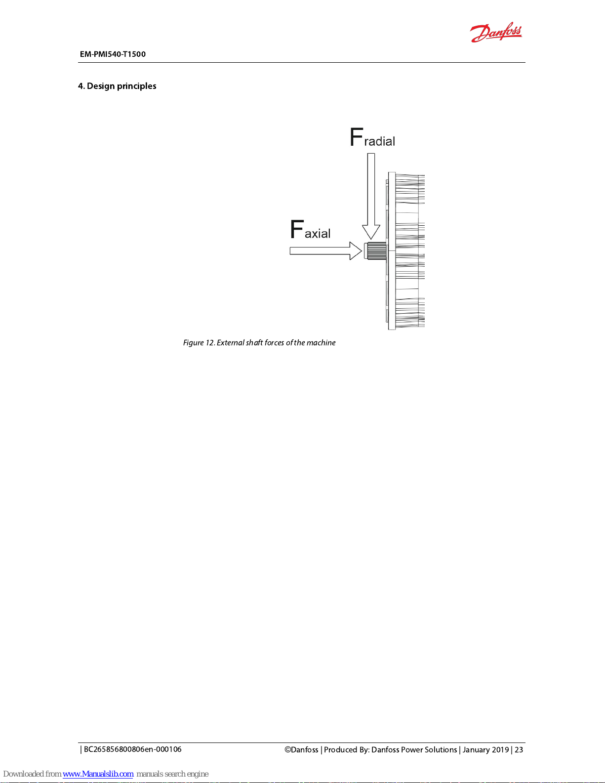
Figure 12. External shaft forces of the machine
EM-PMI540-T1500
4. Design principles
| BC265856800806en-000106
©
Danfoss | Produced By: Danfoss Power Solutions | January 2019 | 23
Page 25
Transportation
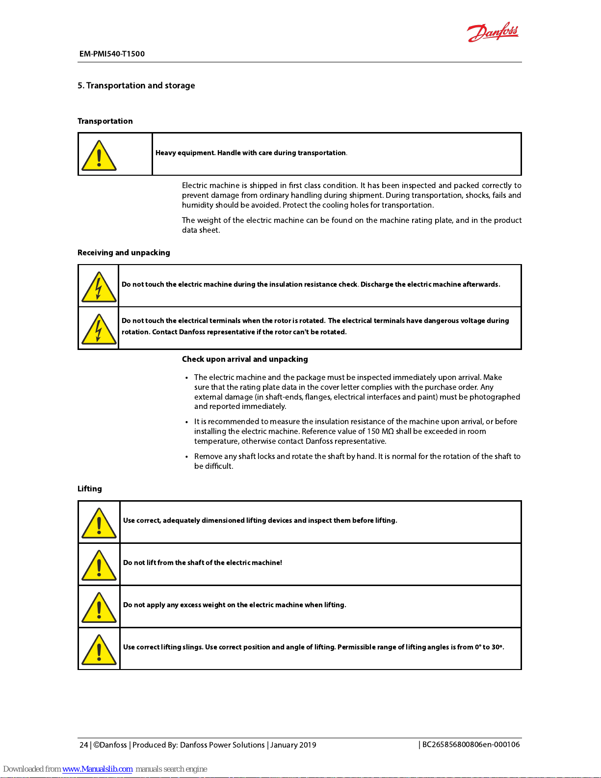
Heavy equipment. Handle with care during transportation
.
Electric machineisshipped in rst class condition. It hasbeen inspected and packed correctlyto
prevent damage from ordinary handling during shipment. During transportation, shocks, fails and
humidity should be avoided. Protectthe cooling holes for transportation.
The weight of the electric machine can be found on the machine rating plate, and in the product
data sheet.
Receiving and unpacking
Do not touch the electric machine during the insulation resistance check. Discharge the electric machine afterwards.
Do not touchthe electrical terminals when the rotoris rotated. The electrical terminals have dangerous voltage during
rotation. Contact Danfoss representative if the rotorcan't be rotated.
Check upon arrival and unpacking
The electric machine and the package must be inspected immediately upon arrival. Make
surethat the rating plate data in the cover letter complieswith the purchase order. Any
external damage (in shaft-ends, anges, electrical interfacesand paint) must be photographed
and reported immediately.
It is recommended to measurethe insulation resistance of the machine upon arrival, or before
installing the electric machine.Reference value of150 MΩ
shall be exceeded in room
temperature, otherwise contact Danfoss representative.
Remove any shaft locks androtate theshaft by hand. It is normal for the rotation of the shaftto
be difficult.
Lifting
Use correct, adequately dimensioned lifting devices and inspect thembefore lifting.
Do not lift from the shaft of the electric machine!
Do not apply any excess weight on the electric machine when lifting.
Use correct lifting slings. Use correct position and angle of lifting. Permissible range of lifting angles is from 0° to 30º.
EM-PMI540-T1500
5. Transportation and storage
24 | ©Danfoss | Produced By: Danfoss Power Solutions | January 2019
| BC265856800806en-000106
Page 26
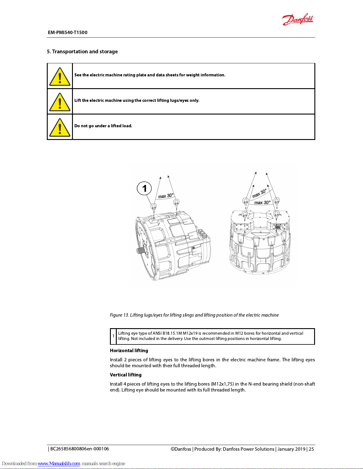
See the electric machine rating plate and data sheets for weight information.
Lift the electric machine using the correct lifting lugs/eyes only.
Do not go under a lifted load.
Figure 13. Lifting lugs/eyes for lifting slings and lifting position of the electric machine
1
Lifting eye type of ANSI B18.15.1M M12x19 is recommended in M12 bores for horizontal and vertical
lifting. Not included in the delivery. Use the outmost lifting positions in horizontal lifting.
Horizontal lifting
Install 2 pieces of lifting eyes to the lifting bores in the electric machine frame. The lifting eyes
should be mounted with their full threaded length.
Vertical lifting
Install 4 pieces of lifting eyes to the lifting bores (M12x1,75) in the N-end bearing shield (non-shaft
end). Lifting eye should be mounted with its full threaded length.
EM-PMI540-T1500
5. Transportation and storage
| BC265856800806en-000106
©
Danfoss | Produced By: Danfoss Power Solutions | January 2019 | 25
Page 27

Storage
Do not touchthe electrical terminals when the shaft is rotated. The electrical terminals have dangerous voltage during
rotation.
Store the electric machine always indoors withthe storage temperature above -20 ºC and the
relative humidity less than 60 %.
The storage should be dry, dust free and vibration free.
Treat the unprotected electric machine surfaces such as the shaft-end and anges against
corrosion. Seal the cable exit holes and cooling bores for storage.
The electric machine must not be subject to any external vibrations during storage to avoid
damage to the bearings.
It is recommendedto use anti-condensation heaters, if tted, or direct winding heating to
avoid water condensing in the electric machine.
Rotate the shaft of the electric machine by hand monthly at least ten revolutions to prevent
grease migration.
Extended storage
Electric machines equipped with relubricable bearings (+BHS option): Apply grease before and
after long term storage.
It is recommendedto inspect the electric machine in storage at periodic intervals. Use attached
storage checklist.
EM-PMI540-T1500
5. Transportation and storage
26 | ©Danfoss | Produced By: Danfoss Power Solutions | January 2019
| BC265856800806en-000106
Page 28
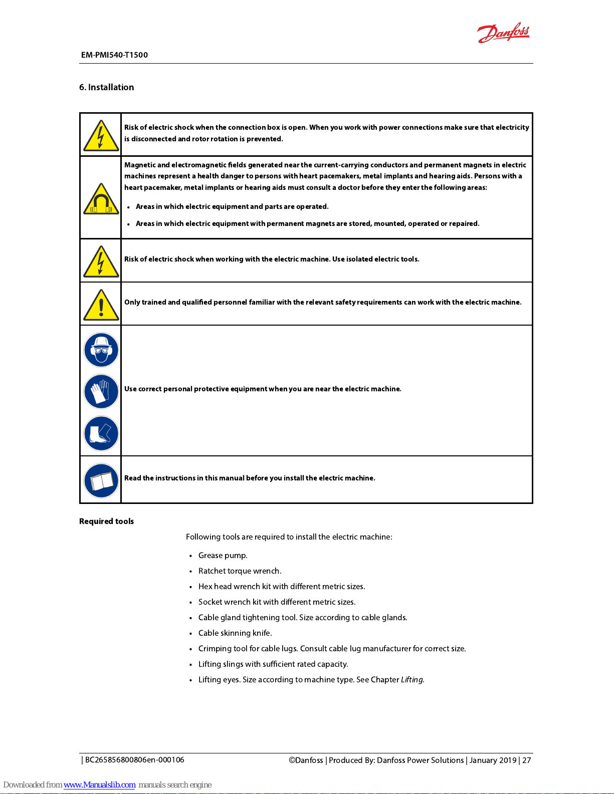
Risk of electric shock when the connection box is open.When you workwith power connections make sure that electricity
is disconnected and rotorrotation is prevented.
Magnetic and electromagnetic elds generated near the current-carrying conductors and permanent magnets in electric
machines represent a health danger to persons with heart pacemakers, metal implants and hearing aids. Persons with a
heart pacemaker, metal implants or hearing aids must consult a doctor before they enter the following areas:
Areas in which electric equipment and parts are operated.
Areas in which electric equipment with permanent magnets are stored, mounted, operated or repaired.
Risk of electric shock when working with the electric machine. Use isolated electric tools.
Only trained and qualied personnel familiar with the relevant safety requirements canwork withthe electric machine.
Use correctpersonal protective equipment when you arenear the electric machine.
Read the instructions in thismanual before you installthe electric machine.
Required tools
Following tools are required to install the electric machine:
Grease pump.
Ratchet torque wrench.
Hex head wrench kit with different metric sizes.
Socket wrench kit with different metric sizes.
Cable gland tightening tool. Size according to cable glands.
Cable skinning knife.
Crimping tool for cable lugs. Consult cable lug manufacturer for correct size.
Lifting slings with sufficient rated capacity.
Lifting eyes. Size according to machine type. See Chapter
Lifting
.
EM-PMI540-T1500
6. Installation
| BC265856800806en-000106
©
Danfoss | Produced By: Danfoss Power Solutions | January 2019 | 27
Page 29

Insulation resistance test
Do not touch the electric machine during theinsulation resistance check. Discharge the machine afterwards.
Measure the insulation resistance of the electric machine before the installation of the electric
machine. Because of the structure of the electric machine it is possible that the stator is damaged
during the installation.The reference value of150 MΩ
mustbe exceeded in room temperature.
Contact Danfossrepresentative if the reference value is not exceeded.
Mechanical installation
Allowed mounting positions
Theelectric machine with standard horizontal mounting optionmust be installedhorizontally. It
can be turned around its axis (shaft) for maximum of 45° to both directions from its default
assembly direction.See Figure below.
The electric machine canbe installedhorizontally or vertically (MHV option).See Figures below.
Figure 14. Allowed horizontal mounting position of the electric machine, mounting option 2
EM-PMI540-T1500
6. Installation
28 | ©Danfoss | Produced By: Danfoss Power Solutions | January 2019
| BC265856800806en-000106
Page 30

Figure 15. Allowed vertical mounting position of the electric machine, mounting option 3
Mounting the electric machine
Do not to exceed the maximum axial and radial forces calculated for the shaft with the documentDOC-000454.
Do not use the N-end of the electric machine for mounting the electric machine.
Refer to chapterAllowed mounting positionsfor the correct mounting positions of the electric machine.
Mount the electric machine on a correct supporting structure that is discussed in chapter
"Supporting structure requirements".
1. Lift the electric machine to the correct mounting position. See Chapter Liftingfor details
.
2. The electric machine is mounted from its D-end ange (SAE1/2 transmission housing ange).
SAE1/2 ywheel housing is required as a mating ange.The mounting foot rails in the side of the
electric machine (4 pieces) can also be used for mounting.
3. Align the electric machine with the mating housing alignment. See ChapterShaft alignment
and load.
4. Connect the shaft of the electric machine, make sure to use full spline engagement. Lubricate
the spline.
A recommended spline lubricant is a 50/50 compound of a high temperature greaseand a molybdenum disulphide
powder.When applied initially and re-applied atproper intervals, it will help preventfretting corrosion and premature
wear.This lubricant is not soluble in oil andshould be used accordingly. Furtherproducts which may be recommended
areMolycote, Metaux, Never Seeze, Optimoland similar.
EM-PMI540-T1500
6. Installation
| BC265856800806en-000106
©
Danfoss | Produced By: Danfoss Power Solutions | January 2019 | 29
Page 31

5.Attach the mounting bolts. For steel housing the minimum lenght of the bolt is 40 mm and for
aluminium housing 45 mm.
Use tightening torque of 69 Nm for D-end bolts. The N-end of theelectric machine is not intended to be be used for
mounting.
Figure 16. Mechanical mounting connections of the electric machine (horizontal mounting)
EM-PMI540-T1500
6. Installation
30 | ©Danfoss | Produced By: Danfoss Power Solutions | January 2019
| BC265856800806en-000106
Page 32

1 Shaft of the electric machine; spline structure of the shaft (DIN5480 W55x2x30x26x8a).
2 D-end ange (SAE1/2) and bolt bores for mounting the machine (12 pieces).
3 Bores for the lifting eyes.
4 Mounting foot rails (see
Main dimension drawing
).
5 Mounting bolts (12 pcs of DIN912 M12 socket head). Not included in the delivery.
Vertical assembly
In vertical assembly, follow the steps givenin the previous chapter "Horizontal assembly".
Figure 17. Mechanical mounting connections of the electric machine (vertical mounting)
1 Mounting foot rails (4 rails in 90º circular pattern around the frame).
2 Bores for the lifting eyes, N-end.
3 D-end ange (SAE1/2) and bolt bores for mounting the machine (12 pieces).
4 Shaft of the machine; spline structure of the shaft (DIN5480 W55x2x30x26x8a).
5 Mounting bolts (12 pcs of DIN912 M12 socket head). Not included in the delivery.
EM-PMI540-T1500
6. Installation
| BC265856800806en-000106
©
Danfoss | Produced By: Danfoss Power Solutions | January 2019 | 31
Page 33

Cooling connections
Make sure that cooling liquid runs freely into and out from the machine.
Connect the electric machine properly to the cooling circuit. Ensure that the coolant ow is equal
or higher than rated and the coolant temperature at the inlet of the machine cooling is lower or
equal to the rated temperature. For more information, see Chapter Recommended coolantsand
product data sheet. Rated values can be found in the electric machine rating plate.
It is recommendedto use coolant connector equipped with o-ring seal or to use sealing washer
(for exampleUsit or Bonded seals) in the connection. In addition, it is recommendedto use thread
sealant (Loctite 577 or similar) at the coolant connections to prevent loosening. Loosening can be
caused by vibration or temperature variations.
The electric machines are equipped with at least three PT100 temperature sensors in the windings.
The amount of the sensors depend on the options chosen. The temperature signal(s) can be read
out from the measurement connector of the machine.
You can connect the temperature signal to the temperature monitoring pin in the inverter (EC-C)
and make sure that the inverter has the machine temperature protection feature activated.
Electrical installation
Power connections
High voltage connection
Risk of electric shock when connection box is open. When you workwith power connections make sure that electricity is
disconnected and shaft rotation is prevented.
The high voltage cables of the electric machine are connected to the connection box, or
connection boxes of the machine. Figure belowshowsthe components of the high voltage
connection box assembly.
1. Remove the cover of the terminal box.
2. Install the power cables according to the wiring diagram.
3. Replacethe cover of the terminal box.
EM-PMI540-T1500
6. Installation
32 | ©Danfoss | Produced By: Danfoss Power Solutions | January 2019
| BC265856800806en-000106
Page 34

Figure 18. High voltage connection assembly structure
1 Mounting bolts (7 pcs) for coverplate
2 Connection box cover plate
3 Connection box cover plate gasket
4 Mounting bolts (4 pcs) for connection box
5 Connection box frame
6 Cable glands (3 pcs/ connection box)
7 Insulation sheet
8 Phase connection points (L1, L2, L3) for one phase
9
Low voltage (measurement) and anti condensation heater connection part (see Chapters Low voltage
(measurement signal) connections and Anti condensation heater connections)
10 Connection box gasket
EM-PMI540-T1500
6. Installation
| BC265856800806en-000106
©
Danfoss | Produced By: Danfoss Power Solutions | January 2019 | 33
Page 35
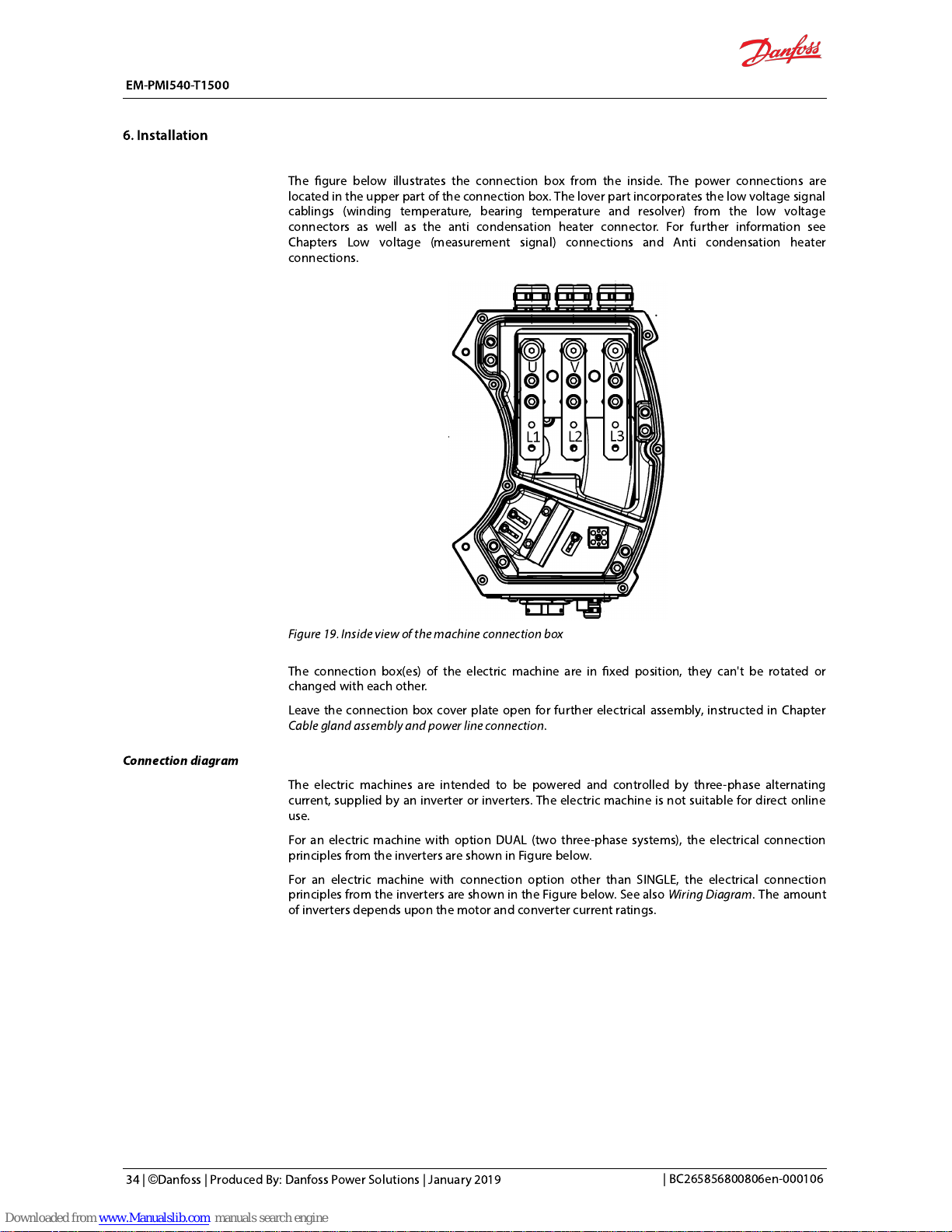
The gure below illustrates theconnection box from the inside. The power connections are
located in the upper part of the connection box. The lover part incorporates the low voltage signal
cablings (winding temperature, bearing temperature and resolver) from the low voltage
connectors as well as the anti condensation heater connector. For further information see
Chapters Low voltage (measurement signal) connections and Anti condensation heater
connections.
Figure 19. Inside view of the machine connection box
The connection box(es) of the electricmachine are in xed position, they can't be rotated or
changed with each other.
Leave the connection box cover plate open for further electrical assembly, instructed in Chapter
Cable gland assembly and power line connection
.
Connection diagram
The electric machines are intended to be powered and controlled by three-phase alternating
current, supplied by an inverter or inverters. The electric machineisnot suitable for direct online
use.
For an electric machine with option DUAL (two three-phase systems), the electrical connection
principles from the inverters are shown in Figure below.
For an electric machine with connection option other than SINGLE, the electrical connection
principles from the inverters are shown in the Figure below. See also
Wiring Diagram
. The amount
of inverters depends upon the motor and converter current ratings.
EM-PMI540-T1500
6. Installation
34 | ©Danfoss | Produced By: Danfoss Power Solutions | January 2019
| BC265856800806en-000106
Page 36
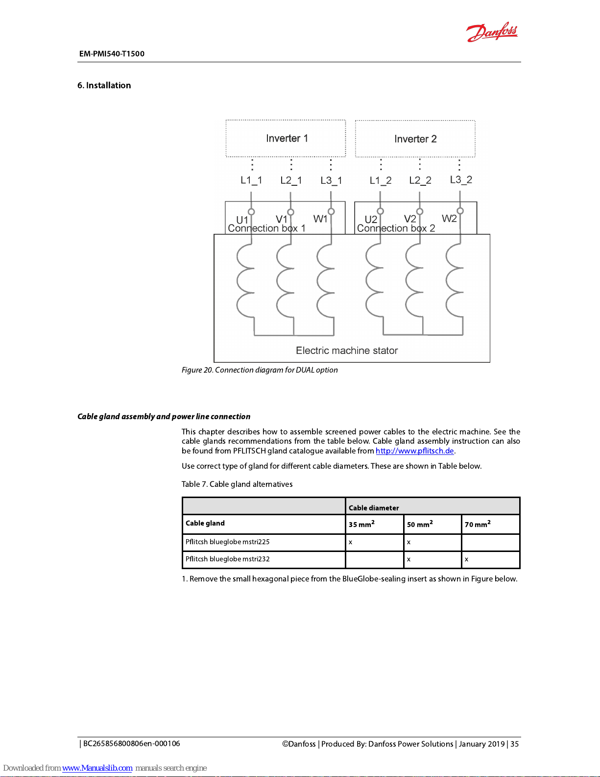
Figure 20. Connection diagram for DUAL option
Cable gland assembly and power line connection
This chapter describes how to assemble screened power cables to theelectric machine. See the
cable glands recommendations from the table below. Cable gland assembly instruction can also
be found from PFLITSCH gland catalogue available from http://www.pitsch.de.
Use correct type of gland for different cable diameters. These are shown in Table below.
Table 7. Cable gland alternatives
Cable diameter
Cable gland
35 mm
2
50 mm
2
70 mm
2
Pitcsh blueglobe mstri225 x x
Pitcsh blueglobe mstri232 x x
1. Remove the small hexagonal piece from the BlueGlobe-sealing insert as shown in Figure below.
EM-PMI540-T1500
6. Installation
| BC265856800806en-000106
©
Danfoss | Produced By: Danfoss Power Solutions | January 2019 | 35
Page 37
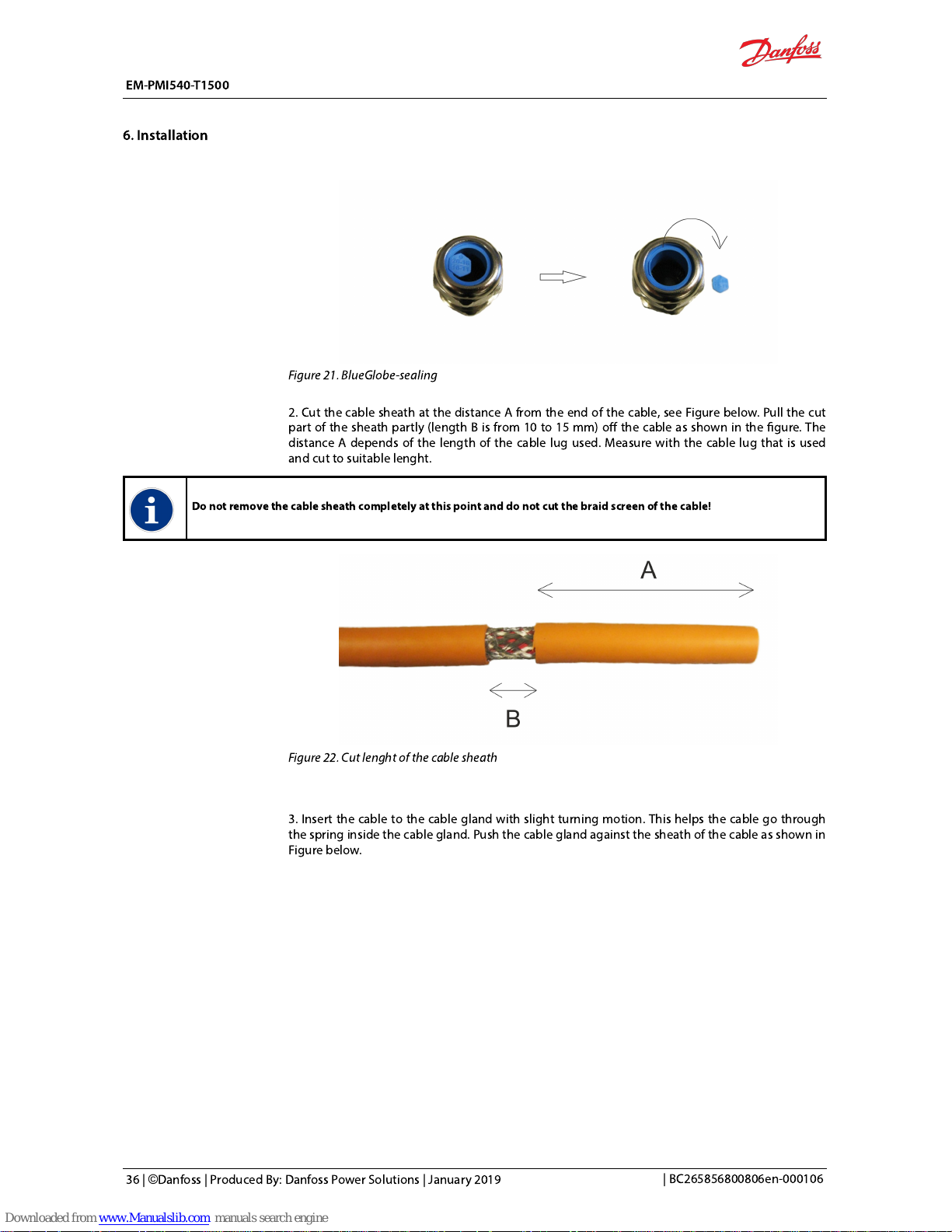
Figure 21. BlueGlobe-sealing
2. Cut the cable sheath at the distance A from the end of the cable, see Figure below. Pull the cut
part of the sheath partly (length B is from 10 to 15 mm) off the cable as shown in the gure. The
distance A depends of the length of the cable lugused.Measure with the cable lug that is used
and cut to suitable lenght.
Do not remove the cable sheath completely at this point and do not cut the braid screen of the cable!
Figure 22. Cut lenght of the cable sheath
3. Insert the cable to the cable gland with slight turning motion. This helps the cable go through
the spring inside the cable gland. Push the cable gland against the sheath of the cable as shown in
Figure below.
EM-PMI540-T1500
6. Installation
36 | ©Danfoss | Produced By: Danfoss Power Solutions | January 2019
| BC265856800806en-000106
Page 38

Figure 23. Cable to the gland assembly
4. After the cable gland is in place remove the length A piece of the sheath and cut the braid
screen (cover) from 10 mm (distance C) from the gland bottom as shown in Figure below.
Make sure that the cable gland spring is against the cable sheath before cutting the braid screen.
Figure 24. Cut the braid screen
5. Cut a piece of length D of the inner sheath shown in Figure Cutting the inner sheath. The length
D must equal to the length of the cable lug body.
EM-PMI540-T1500
6. Installation
| BC265856800806en-000106
©
Danfoss | Produced By: Danfoss Power Solutions | January 2019 | 37
Page 39

Figure 25. Cutting the inner sheath
6. Place the cable inside the cable lug body, and crimp the cable lug twice in different places. See
Figure below.
Figure 26. Connecting cable lug
7. Cut piece of shrink tube and shrink it over the cable lug and braid screen as shown in Figure
below. This is done to keep the braid screen in place and for extra insulation.
The shrink tube must be specied for operating temperature range from -40 ºC to 150 ºC. Self gluing shrink tube is
recommended.
EM-PMI540-T1500
6. Installation
38 | ©Danfoss | Produced By: Danfoss Power Solutions | January 2019
| BC265856800806en-000106
Page 40

Figure 27. Shrink tube
8. Insert the cable through the corresponding hole in the connection box and connect the cable
lug to the connection point. Use spring washer between the cable lug and the connection screw
or nut. Example of the connection is shown in Figure below. Do not tighten the connection at this
point to ensure tting of the cable gland.
Make sure that there is at least 10 mm air gap between the cable lug and other metallic structures including the braid of
the cable. If the air gap is smaller, use extra insulation shrink tube to cover the lug.
Figure 28. Cable lug connection to the connection box (example only, the connection box may look
different)
9. Screw the cable gland to the connection box as shown in Figure below. Tighten the cable gland
from the cap of the gland. See Chapter Tightening torques.
EM-PMI540-T1500
6. Installation
| BC265856800806en-000106
©
Danfoss | Produced By: Danfoss Power Solutions | January 2019 | 39
Page 41

Do not turn the body of the gland! By tightening from the cap of the gland the cable is sealed to the cable gland and at
the same time the cable gland is tightened to the connection box with correct torque.
10. Tighten the cable lug. Use tightening torque of 15 Nm.
11. Repeat the procedure to the other cables and connection box.
12. Check that the phase connections order in the connection box is correct, ie. corresponding
phases between the inverter and the machine are connected (U, V, W correspond to the L1, L2, L3
phases).
13. Close the connection box. Tighten the connection box cover screws. See chapter Tightening
torques.
Use thread locking compound that makes it possible to remove the screws. (For example
Loctite 221).
If you must connectthe anti condensation heater, you can leavethe connection box open. See
Chapter Anti condensation heater.
Check the power cable shield grounding, see ChapterGrounding connections.
Low voltageconnections
Plug the unused socket holes of the low voltage connectorwith suitable plugs:
DEUTSCH 0413-003-1605 (size 16)
DEUTSCH 0413-204-2005 (size 20)
The electric machine has aconnector which is used to read out in-built temperature and rotation
sensor (resolver) data from the machine. The temperature data comes from PT100 sensorsin the
stator windings and in some cases inthe bearings. The rating plate has the information about the
options ofthe machine: different options add sensors, and some machines do not have all the
sensors that are listed in the table below. For more information aboutthe options, refer to the data
sheet of the electric machine.
Figure 29. Location of the low voltage connectors in the connection box (N-end of the machine)
1
Low voltage (measurement signal) connector including winding temperature sensors (PT100) and
resolver connections
2 Bearing temperature measurement sensor (PT100) connector in the N-end of the machine
3 Inlet (cable gland) for anti condensation heater cable (see Chapter
Anti condensation heater connections
)
EM-PMI540-T1500
6. Installation
40 | ©Danfoss | Produced By: Danfoss Power Solutions | January 2019
| BC265856800806en-000106
Page 42

Figure 30. Pin conguration of the Deutch HD34-24-47PE connector
Table 8. Pin conguration of theDeutch HD34-24-47PE connector
Measurement Description PIN
Temperature 1
Temperature 1, PT100 (P), windings 47
Temperature 1, PT100 (N), windings 46
Temperature 2
Temperature 2, PT100 (P), windings 33
Temperature 2, PT100 (N), windings 32
Temperature 3
Temperature 3, PT100 (P), windings 45
Temperature 3, PT100 (N), windings 31
Temperature 4
Temperature 4, PT100 (P), windings, option TEMP4 30
Temperature 4, PT100 (N), windings, option TEMP4 29
Temperature 5
Temperature 5, PT100 (P), windings, option TEMP4 44
Temperature 5, PT100 (N), windings, option TEMP4 43
Temperature 6
Temperature 6, PT100 (P), windings, option TEMP4 28
Temperature 6, PT100 (N), windings, option TEMP4 16
Resolver COS_N Resolver, RES_COS_N, in-built non contacting 35
Resolver COS_P Resolver, RES_COS_P, in-built non contacting 20
Resolver SIN_N Resolver, RES_SIN_N , in-built non contacting 36
Resolver SIN_P Resolver, RES_SIN_P , in-built non contacting 21
Resolver EXCN Resolver, EXCN, in-built non contacting 22
Resolver EXCP Resolver, EXCP, in-built non contacting 10
Resolver shield Resolver, SHIELD/GROUND, in-built non contacting 34
EM-PMI540-T1500
6. Installation
| BC265856800806en-000106
©
Danfoss | Produced By: Danfoss Power Solutions | January 2019 | 41
Page 43

Figure 31. Bearing temperature measurement connector (optional)
1 PT-100 pin.
2 PT-100 pin.
3 PT-100 ground pin.
4 PT-100 ground pin.
Grounding connections
The grounding points on the frame of the electric machine are for safetygrounding, and signal cables and power cable
shields have their own grounding points.
For proper and safe operation, it is important to ensure proper grounding (earthing) of the
machine and cable shields connected to the machine. In the electric machine the middle lifting
bores can be used as a connection point for machine enclosure grounding. The low voltage
(measurement) signal cable is grounded through the ground/shield pins of the low voltage
connector, and the power cables through the cable glands in the connection box.
EM-PMI540-T1500
6. Installation
42 | ©Danfoss | Produced By: Danfoss Power Solutions | January 2019
| BC265856800806en-000106
Page 44

Figure 32. The machine enclosure grounding point, safety grounding
Figure 33. Low voltage cable grounding points
EM-PMI540-T1500
6. Installation
| BC265856800806en-000106
©
Danfoss | Produced By: Danfoss Power Solutions | January 2019 | 43
Page 45

Figure 34. Power cable grounding through the cable gland
Testing the power cable shield grounding(earthing)
The power cable shields are grounded (earthed) through the cable glands to the connection box
and further to the electric machine enclosure. After the cable gland assembly and power cable
installations, and any time when needed, make sure that the grounding (earthing) connections are
correct.
1. Connect one terminal of the measurement device to the cable shield of one power cable (in
the inverter end of the cable)
2. Connect the other terminal of the measurement device to the cable shield of an other power
cable. You can also use the machine enclosure grounding point for the measurement.
3. Measure the resistance between the two cable shields or between the cable shield and the
enclosure grounding point.
4. Change the measurement device terminal(s) to the shield of different power cable and repeat
the measurement until all cables have been measured.
Testing the low voltage (measurement signal) cable shield grounding (earthing)
The low voltage (measurement signal) cable shield connects to the ground through the connector
grounding/earthing pins, see Figure Low voltage cable shield grounding. After cable installation,
and any time when needed, make sure that the grounding (earthing) connection is valid.
1. Connect one terminal of the measurement device to the low voltage cable shield (in the non-
machine end of the cable).
2. Connect the other terminal of the measurement device to the machine enclosure grounding
point.
3. Measure the resistance between the cable shield and the enclosure grounding point.
EM-PMI540-T1500
6. Installation
44 | ©Danfoss | Produced By: Danfoss Power Solutions | January 2019
| BC265856800806en-000106
Page 46

Anti-condensation heater connections
Do not run the electric machine when the anti-condensation heater is in use.
Water condensing inside the electric machine enclosure can result in failure or corrosion ofthe
machine. This often happens in cooler temperatures or higher humidity areas typically in marine
environment, when the machine is not running.
The electric machinecan be equipped with anti-condensation heater to avoid condensation
issues. The heater (+HEAT1) or heaters (+HEAT2)arefactory assembled see Figure Heater
connector locations . The installed heater may not be used when the machine mains are switched
on, and the machine is running.
The installed anti condensation-heater must be supplied with 230 Vacpower. The heater
connector is inside the connection box, in the lower part if it. The anti-condensation heater cable
has an inlet (cable gland) next to the low voltage signal connector. See Figure below.
Figure 35. Anti-condensation heater connector
1 Anti-condensation heater connector (inside the connection box).
2 Inlet and cable gland for the anti condensation heater cable.
After installation of the machine, and any time when needed, the resistance of the warming
element can be measured. Connect the measurement device between the heater terminals. The
resistance shall be around1 kΩ. Measuring no value, or zero value indicates a possible failure in
the heater element.
If the electric machine has an anti-condensation heater and failure is suspected, contact
Danfossrepresentative.
EM-PMI540-T1500
6. Installation
| BC265856800806en-000106
©
Danfoss | Produced By: Danfoss Power Solutions | January 2019 | 45
Page 47

Only trained and qualied personnel familiar with the relevant safety requirements are allowed to operate the electric
machine.
Do not usethe electric machine without properly dimensioned and operating cooling system. Maximum operation
temperature, current and rotational speed of the electric machine must not be exceeded to avoid permanent damage.
The surface of the electric machine might be hot.Do not touch the electric machine during operation.
Entanglement hazard! Do not touch the electric machineduring operation.
Do not run the electric machine when the heater is in use.
Use sufficient personal protective equipment when you arenear the electric machine.
Read the instructions in the manual before you installthe electric machine.
Operation conditions
The electric machine should be used for its intended purpose only and within limits specied by
the manufacturer, concerning:
Loading.
Cooling.
Speed range.
Service interval.
Ambient condition such as temperature and moisture.
EM-PMI540-T1500
7. Operation
46 | ©Danfoss | Produced By: Danfoss Power Solutions | January 2019
| BC265856800806en-000106
Page 48

The electric machineisdesigned for the following conditions:
Ambient temperature limits:-40°C ...+40 °C.
Maximum altitude 2000 m above sea level.
Maximum coolant liquid temperature at the inlet of the coolant circuit, see product data sheet.
Coolant liquid must be water- glycol mixture with maximum of 50 % glycol content. See
ChapterRecommended coolants.
If electric machine operation limits are exceeded, please contact Danfossrepresentative.
Condition monitoring during operation
Supervising the electric machine correctlyduring the operation ensures reliable operation and designed lifetime.
If you notice any deviations from the normal operation, for example elevated temperatures, noise or vibration, stop the
electric machine.Find the reason for thedeviationand repair the electric machine.Refer to Chapter 9
Troubleshooting
.
Maximum temperature of the bearings of the electric machine is 120°C.
Maximum temperature of the windingsof the electric machine is 150°C.
Recommended lubricants
Do not mix different types of grease! Consult SKF for using other greases.
Greased for life bearingsdo not need relubrication during their lifetime. Grease relubricable
bearings (BHS option) need regular greasing. See Chapter
Maintenance - Bearings and
lubricationfor further information.
The recommended grease type for the machine bearings is SKF LGHP-2 or equivalent. LGHP-2 is
high performance, high temperature bearing grease. For further information, see
http://www.skf.com/
Each electric machine has its own greasing recommendations, see the sticker on the electric
machine or contact Danfoss.
EM-PMI540-T1500
7. Operation
| BC265856800806en-000106
©
Danfoss | Produced By: Danfoss Power Solutions | January 2019 | 47
Page 49
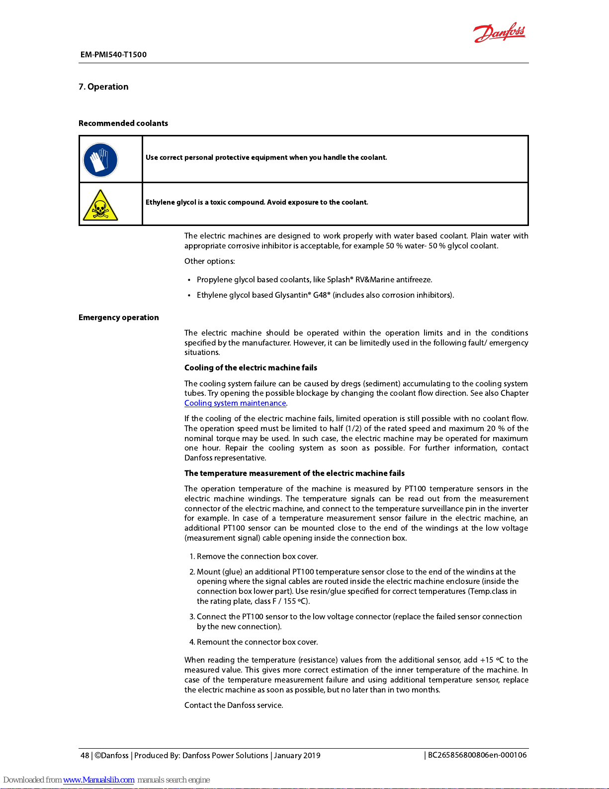
Recommended coolants
Use correctpersonal protective equipment when you handlethe coolant.
Ethylene glycol is a toxic compound. Avoid exposure to the coolant.
The electric machines are designed to work properly with water based coolant. Plain water with
appropriate corrosive inhibitor is acceptable, for example50 % water- 50 % glycol coolant.
Other options:
Propylene glycol based coolants, like Splash® RV&Marine antifreeze.
Ethylene glycol based Glysantin® G48® (includes also corrosion inhibitors).
Emergency operation
The electric machine should be operated within the operation limits and in the conditions
specied by the manufacturer. However, it can be limitedly used in the following fault/ emergency
situations.
Cooling of the electric machine fails
The cooling system failure can be caused by dregs (sediment) accumulating to the cooling system
tubes. Try opening the possible blockage by changing the coolant ow direction. See also Chapter
Cooling system maintenance.
If the cooling of the electric machine fails, limited operation is still possible with no coolant ow.
The operation speed must be limited to half (1/2) of the rated speed and maximum 20 % of the
nominal torque may be used. In such case, the electric machine may be operated for maximum
one hour. Repair the cooling system as soon as possible. For further information, contact
Danfossrepresentative.
The temperature measurement of the electric machine fails
The operation temperature of the machine is measured by PT100 temperature sensors in the
electric machine windings. The temperature signals can be read out from the measurement
connector of the electric machine, and connect to the temperature surveillance pin in the inverter
for example. In case of a temperature measurement sensor failure in the electric machine, an
additional PT100 sensor can be mounted close to the end of the windings at the low voltage
(measurement signal) cable opening inside the connection box.
1. Remove the connection box cover.
2. Mount (glue) an additional PT100 temperature sensor close to the end of the windins at the
opening where the signal cables are routed inside the electric machine enclosure (inside the
connection box lower part). Use resin/glue specied for correct temperatures (Temp.class in
the rating plate, class F / 155 ºC).
3. Connect the PT100 sensor to the low voltage connector (replace the failed sensor connection
by the new connection).
4. Remount the connector box cover.
When reading the temperature (resistance) values from the additional sensor, add +15 ºC to the
measured value. This gives more correct estimation of the inner temperature of the machine.In
case of the temperature measurement failure and using additional temperature sensor, replace
the electric machine as soon as possible, but no later than in two months.
Contact the Danfossservice.
EM-PMI540-T1500
7. Operation
48 | ©Danfoss | Produced By: Danfoss Power Solutions | January 2019
| BC265856800806en-000106
Page 50

This chapter contains necessary information for the qualied and trained personnel to carry out
regular maintenance work.
Do not disassemble the machine. Only procedures described in this manual may be done.
Only trained and qualied personnel familiar with the relevant safety requirements are allowed to domaintenance to the
electric machine.
Risk of electric shock when the connection box is open.
Voltage may be connected to the anti-condensation heater.
Use correctpersonal protective equipment when you are near the electric machine.
Read the instructions in the manual before you start to work withthe electric machine. To ensure safe and reliable
operation of the machine, obey the maintenance instructionscarefully.
Regular maintenance
Inspect the machine at regular intervals. Use the regular maintenance checklists for help.
Do not attempt to tighten bolts or screws that are not discussed in this manual and that are not needed for normal
installation and maintenance procedures.The sealing of the bolts and screws canbreak.
Correct supervision and maintenance of the electric machine makes sure of reliable operation and
designed lifetime.
EM-PMI540-T1500
8. Maintenance
| BC265856800806en-000106
©
Danfoss | Produced By: Danfoss Power Solutions | January 2019 | 49
Page 51

Table 9. Maintenance schedule
Object Check/Task Weekly Monthly Yearly
General
construction
Operation Noise, vibration. If clearly increased, contact Danfoss. X
Mounting
Bolttightness. Tighten to proper value if necessary. Applies to bolts and screws
that are discussed in this manual. See chapter Tightening torques.
X
Bearings Listen to any unusual noise or vibration. If exists, contact Danfoss. X
Enclosure and
connected parts
Check cleanliness. Clean if necessary. See ChapterCleaning. X
Shaft seals Check the wear. Replace if necessary. X
Electrical
system
Cables Wearing of the cables. Replace if necessary. X
Electrical
connections
Check connections. Ensure that sufficient tightening torque is applied to cable
glands. See chapter Tightening torques.
X
Groundings
(earthings)
Check groundings (earthings). Make sure that the connection resistance is
valid. Re-connect if necessary.
X
Anti-
condensation
heater
Check anti-condensation heater connections and resistance, if option installed.
If needed, contact Danfoss.
x
Cooling
system
Operation Functioning. Cooling system functions as specied. X
Tubing and
connection
tightness
No visible leakage. If leaking, tighten connections appropriately, or replace
parts.
X
Ventilation plug Cleanliness. Clean if necessary. See chapterCleaning. X
Coolant ow
Coolant ow direction. Change direction by changing the connections or ow
direction from the pump. See Chapter Cooling system maintenance.
X
Coolant quality
Coolant as specied. Proper glycol used, and water/glycol mixture appropriate.
Rell if necessary. See Chapter Cooling system maintenance.
X
Lubrication
Relubrication
(BHS option)
Relubricate depending on the use (see ChapterBearings and lubrication), if the
option has beeninstalled. Maximum relubrication interval is six months.
X
Cleaning
Keep the electric machine clean. For cleaning, use non-abrasive and non-corrosive cleaning
products. Make sure that the detergent may be used for aluminium.
When pressure washing the machine, make sure that the water spray does not directly hit the
gaskets.
When cleaning the ventilation plugs, do not open / remove the plug. Clean the plug onlyfrom
theoutside.
Bearings and lubrication
Grease relubricable bearings (BHS option)
The mechanical bearing lifetime (grease relubricable bearings) of the machine is shown below. It
depends on the bearing operation temperature and rotation speed.
The expression of L
10
in bearing lifetime information is a standard way of expressing the lifetime
and means the time period at the end of which 90% of the bearings are still reliably
working.Grease relubricable bearings (BHS option) need regular greasing. This is due to the
limited lubricant (grease) lifetime in operation conditions, and is shorter time period than the
actual bearing lifetime.
EM-PMI540-T1500
8. Maintenance
50 | ©Danfoss | Produced By: Danfoss Power Solutions | January 2019
| BC265856800806en-000106
Page 52

The bearing type for electric machinewith option BHS is SKF 6214 C3 (non-insulated bearings) or
SKF 6214 C3 HC5 (insulated bearing). See the recommended lubricant in Chapter
Recommended
lubricants.
Bearing relubrication
Beware of rotating parts. Do not touch the electric machine during operation.
The surface of the electric machine canbe hot. Use correct protective equipment (heat resistant gloves) when you
handlethe electric machine.
The information of bearing lifetime and bearing grease lifetime are estimations only to provide a magnitude of them. The
bearing lifetime and bearing grease lifetime in customer application may vary. Danfossis not responsible for the actual
bearing lifetime in use. For further information contact Danfossrepresentative
.
The maximum relubrication interval in operation is 6 months.The amount of grease per relubrication is 20 g.
The relubrication interval depends on the used rotation speed and bearing temperature, and is
presented in Figure below. The different curves represent different bearing temperatures. The
higher the temperature is and the higher the rotation speed is, the lower the relubrication interval
is.
EM-PMI540-T1500
8. Maintenance
| BC265856800806en-000106
©
Danfoss | Produced By: Danfoss Power Solutions | January 2019 | 51
Page 53
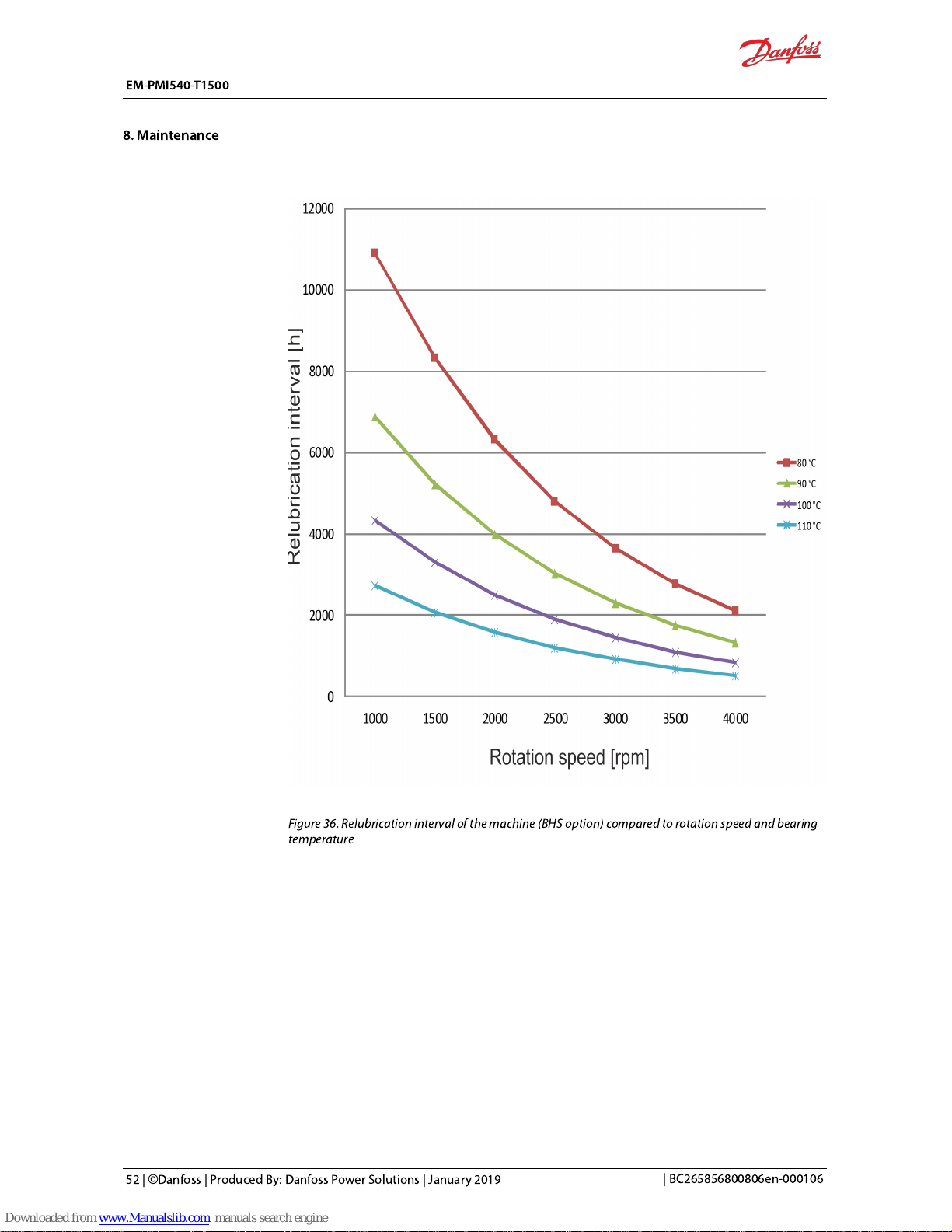
Figure 36. Relubrication interval of the machine (BHS option) compared to rotation speed and bearing
temperature
EM-PMI540-T1500
8. Maintenance
52 | ©Danfoss | Produced By: Danfoss Power Solutions | January 2019
| BC265856800806en-000106
Page 54

Figure 37. Relubrication interval of the machine (BHS option) compared to rotation speed and bearing
temperature, vertical installation
Bearing relubrication:
1. Make sure that the machine has reached its operating temperature.
2. Remove the plugs from the grease escape holes.
3. Open the grease nipple plugs.
4. Use grease piston to enter specic amount of grease into the grease nipple.
5. If possible, let the machine run approximately one hour to let the old grease exit. NOTE! It is
normal if no grease exits the electric machine. This is because the cavities inside the electric
machine can hold a lot of grease.
6. Install the plugs on the grease nipples and on the grease escape holes.
Cooling system maintenance
The electric machine cooling system requires certain regular maintenance activities.
The coolant liquid ow direction must be changed yearly. This is done by changing the order of
the coolant connections, or changing the coolant pump direction. The reason for changing the
coolant ow direction is to prevent possible dregs (sediment) accumulating to the cooling system.
The quality of the coolant must be checked yearly. The mixture of water and glycol as well as the
type of the glycol used must be as specied. See ChapterRecommended coolants
.
EM-PMI540-T1500
8. Maintenance
| BC265856800806en-000106
©
Danfoss | Produced By: Danfoss Power Solutions | January 2019 | 53
Page 55

Make sure that the mating structure isnot damaged.
Do not pluck any bores or use at headed bolts or rods for pushing
the electric machine out of the mating structure.
For dismounting the electric machine, follow the steps below.
1. Installcorrectlifting eyes to the lifting bores in the machine frame, and the lifting slings to the
lifting eyes. Support the machinewith lifting slings when dismounting. Refer to ChapterLifting.
2. Loosen the mounting bolts, for more information refer toChapter Mounting the electric
machine.
3. If axial force is required, use the bores in D-end ange to push the electric machine out from the
mating structure.
EM-PMI540-T1500
9. Dismounting
54 | ©Danfoss | Produced By: Danfoss Power Solutions | January 2019
| BC265856800806en-000106
Page 56

Some difficulties may occur while operating the electric machine. Possible causes and actions are
given in Table below. If the situation occurs, it should be corrected as soon as possible.These
instructions do not cover all details or variations in the equipment nor provide information for
every possible condition to be met in connection with installation, operation or maintenance.
Contact Danfoss for more information.
Table 10. Troubleshooting chart
Symptom Possible cause Action
Excessive vibration, noise
Unbalance at the connected
machine or the powertrain
components.
Check the balance and installation of the actuator and drivetrain components.
Misalignment between the
electric machine and the used
device.
Check the connections and couplings.
Attachment bolts are loose. Replace and tighten the bolts.
Clearance at the spline
connection.
Check the spline connection.
Imbalance at the electric
machine.
Contact Danfoss.Particles inside the electric
machine.
Bearing damage.
Inadequate lubrication
(electric machine with BHS
option).
Apply bearing lubricant/grease. See ChapterBearings and lubrication. Contact
Danfoss for further information.
Bearing temperature rise
Inadequate lubrication
(electric machine with BHS
option).
Apply bearing lubricant/grease. See Chapter Bearings and lubrication.
Too much grease at the
bearing housing (electric
machine with BHS option).
Open grease escape valve and let the electric machine run for 10 min. Clean the
grease escape channel from solidied grease using brush if necessary.
Incorrect bearing grease. Check that the used grease is of correcttype.
Incorrect radial lip seal. Check that the correcttype of radial lip seal is used.
Overloaded bearing.
Check that the system is not causing excess force or vibration to the machine
bearings.
Bearing damage. Contact Danfossfor further information.
Electric machine
overheating
Overload.
Reduce load. Check the electric machine model description and rating plate,
check the inverter limits.
Cooling system failure.
Check the cooling system integrity, ow and uid temperature.
Change the cooling ow direction to ush the cooling system from sediment
possibly accumulated. SeeChapterEmergency operation.
Leakage in the cooling system. Check the cooling system circuit and connections.
Rigid particle inside the
machinecooling channel.
Try pulsating coolant to open the channels. Contact Danfoss.
Wrong machine parameters in
the inverter.
Check and correct the machine parameters from the inverter.
Winding short circuit. Replace the electric machine.
EM-PMI540-T1500
10. Troubleshooting
| BC265856800806en-000106
©
Danfoss | Produced By: Danfoss Power Solutions | January 2019 | 55
Page 57

Signicant lubricant leak
Worn radial lip seal. Contact Danfoss.
Block at the grease outlet
channel.
Clean the grease escape channel from solidied grease using brush if necessary.
Electric machine does not
work properly or the
performance is poor
Wrong electric machine
parameters in the inverter.
Check and correct the electric machine parameters from the inverter.
Demagnetization of magnets
due to overheating.
Measure the winding resistance, refer to manufacturer data. Replace the electric
machine if necessary.
Bearing fault. Check the bearings, lubrication and conditions.
Insulation fault.
Measure the insulation resistance, refer to the manufacturer limits. See Chapter
Insulation resistance test.Replace the electric machine if necessary.
Anti-condensation heater
failure
The heater element is faulty.
Measure the resistance of the heater element, see Chapter Anti-condensation
heater connections. If the heater is faulty, contact Danfoss.
Temperature
measurement failure
The PT100 sensor faulty.
Measure the resistance of the PT100 sensor, see ChapterLow
voltageconnections. If the sensor is faulty, read out the signal from another
sensor. Contact Danfoss. SeeChapterEmergency operation.
EM-PMI540-T1500
10. Troubleshooting
56 | ©Danfoss | Produced By: Danfoss Power Solutions | January 2019
| BC265856800806en-000106
Page 58

Service policy
Maintenance and service of the electric machine is limited to the procedures described in this
manual. See Chapter
Service parts
belowfor a list of available service parts. For further information,
contact Danfoss.
Service parts
The recommended service parts are listed in the table below. Quantity describes the number of
components in a single electric machine. Maintenance procedures not decribed in this manual
requirespecial tools and instructions. Contact Danfoss for more information and purchasing.
Figure 38. Recommended service parts
EM-PMI540-T1500
11. Aftersales
| BC265856800806en-000106
©
Danfoss | Produced By: Danfoss Power Solutions | January 2019 | 57
Page 59

Part
number
Item
(order)
number
Qty Description Type
1 10945 1 Seal, O-ring 208 X 4 NBR70
2 10974 1 Seal, Radial lip, D-end
65 X 90 X 10 FKM,
TRELLEBORG, TREB00650-
VCBVR
3 10935 1
Bearing, D-end, Deep groove ball (non insulated in
D-end, BI0, and BIN options)
SKF 6214 C3
3 11093 1
Bearing, D-end, Deep groove ball (insulated in D-
end, BID and BIA options)
SKF 6214 C3 HC5 (hybrid
bearing)
4 10242 1 Seal, O-ring 124,5 X 3 NBR70
5 10546 2 Grease nipple (both in D-end and N-end) DIN 71412, M10 x 1
6 10473 6
Cable gland (power connections), DUAL (two
connection boxes)
M32 X 1.5, BG PFLITSCH
7 10935 1
Bearing, N-end, Deep groove ball (non insulated in
N-end, BI0 and BID options)
SKF 6214 C3
7 11093 1
Bearing, N-end, Deep groove ball (insulated in N-
end, BIN and BIA options)
SKF 6214 C3 HC5 (hybrid
bearing)
8 10451 1 Seal, O-ring 184.5 X 3 NBR70
9 10242 1 Seal, O-ring 124,5 X 3 NBR70
10 10349 7
Plug for Grease escape hole (both in D-end and in
N-end) (horizontal and radial holes)
M16 x 1.5 , VSTI16X1.5SED71
11 10358 1 Ventilation plug PMF 100444 Metal Vent
The bearing type depends on the Bearing insulation option selected.
EM-PMI540-T1500
11. Aftersales
58 | ©Danfoss | Produced By: Danfoss Power Solutions | January 2019
| BC265856800806en-000106
Page 60

Dispose of the electric machine and any of its parts by appropriate means in accordance with local
laws and regulations.
EM-PMI540-T1500
12. Disposal
| BC265856800806en-000106
©
Danfoss | Produced By: Danfoss Power Solutions | January 2019 | 59
Page 61

Electric Machine Installation Checklist
Date:
Table 11. Machine and customer information
Customer: Machine type (from the rating plate):
Customer reference: Machine serial number:
Service reference: Date installed:
N.A = Procedure not applicable PASS = Procedure passed FAIL = Procedure failed
Table 12. Installation checklist
Approval N.A PASS FAIL
General
Machine type is correct
☐ ☐ ☐
Machine is undamaged
☐ ☐ ☐
Insulation resistance check >150M
Ω
☐ ☐ ☐
Environmental conditions as specied (see data sheet)
☐ ☐ ☐
Mechanical installation
Supporting structure as required
☐ ☐ ☐
Shaft alignment as specied (see chapter Shaft alignment and load).
☐ ☐ ☐
D-end attachment bolt tightening torque 40 Nm
☐ ☐ ☐
N-end attachment bolt tightening torque 30 Nm
☐ ☐ ☐
Cooling circuit connected and coolant owing
☐ ☐ ☐
Used coolant:
Power connections
Cable gland assembly as specied (cable gland to cables) with correct cable diameter
☐ ☐ ☐
Cable lug air cap (to metallic structures)
≥
10 mm
☐ ☐ ☐
Cable gland tightening torque (to the box) 15 Nm
☐ ☐ ☐
Cable lug tightening torque (to the busbar) 13 Nm
☐ ☐ ☐
The phase connections order is correct (U, V, W -> L1, L2, L3)
☐ ☐ ☐
Connection box cover bolts tightening torque 4 Nm
☐ ☐ ☐
EM-PMI540-T1500
13. Storage, installation and maintenance checklists
60 | ©Danfoss | Produced By: Danfoss Power Solutions | January 2019
| BC265856800806en-000106
Page 62

Grounding
Machine enclosure grounding connected
☐ ☐ ☐
Low voltage cable shield grounding connected
☐ ☐ ☐
Power cable shield connection resistances to ground (machine enclosure) measured and valid
☐ ☐ ☐
Low voltage cable shield grounding resistances measured and validä
☐ ☐ ☐
Do not try to tighten bolts or screws that are not discussed in the product manual and that are
notneeded for the normal installation procedures. Sealing of the screws may break.
Notes:
-
-
-
-
-
-
-
-
-
Signature: Date:
EM-PMI540-T1500
13. Storage, installation and maintenance checklists
| BC265856800806en-000106
©
Danfoss | Produced By: Danfoss Power Solutions | January 2019 | 61
Page 63

Electric Machine Weekly Maintenance Checklist
Date:
Table 13. Machine and customer information
Customer: Machine type (from the rating plate):
Customer reference: Machine serial number:
Service reference: Date installed:
N.A = Procedure not applicable PASS = Procedure passed FAIL = Procedure failed
Table 14. Electric Machine Weekly Maintenance Checklist
N.A PASS FAIL
General construction
Noise or vibration during operation in general
☐ ☐ ☐
Cooling system
Functioning of the cooling system in general
☐ ☐ ☐
Notes:
-
-
-
-
-
-
-
-
-
EM-PMI540-T1500
13. Storage, installation and maintenance checklists
62 | ©Danfoss | Produced By: Danfoss Power Solutions | January 2019
| BC265856800806en-000106
Page 64

Electric Machine Monthly Maintenance Checklist
Pvm:
Table 15. Machine and customer information
Customer: Machine type (from the rating plate):
Customer reference: Machine serial number:
Service reference: Date installed:
N.A = Procedure not applicable PASS = Procedure passed FAIL = Procedure failed
Table 16.
Electric Machine Monthly Maintenance Checklist
N.A PASS FAIL
General construction
Noise or vibration during operation in general
☐ ☐ ☐
Cleanliness of the enclosure and connected parts
☐ ☐ ☐
Electrical system
Weariness of the cables
☐ ☐ ☐
Cooling system
Functioning of the cooling system in general
☐ ☐ ☐
Tightness of the ventilation plug
☐ ☐ ☐
Cleanliness of the ventilation plug
☐ ☐ ☐
Notes:
-
-
-
-
-
-
-
-
-
EM-PMI540-T1500
13. Storage, installation and maintenance checklists
| BC265856800806en-000106
©
Danfoss | Produced By: Danfoss Power Solutions | January 2019 | 63
Page 65

Electric Machine Yearly Maintenance Checklist
Date:
Table 17. Machine and customer information
Customer: Machine type (from the rating plate):
Customer reference: Machine serial number:
Service reference: Date installed:
N.A = Procedure not applicable PASS = Procedure passed FAIL = Procedure failed
Table 18. Yearly maintenance checklist
Acceptance N.A PASS FAIL
General construction
Noise or vibration during operation in general
☐ ☐ ☐
Mounting bolt tightness
D-end attachment bolt tightening torque 40 Nm
☐ ☐ ☐
N-end attachment bolt tightening torque 30 Nm
☐ ☐ ☐
Cleanliness of the enclosure and connected parts
☐ ☐ ☐
Electrical system
Weariness of the cables
☐ ☐ ☐
Electrical connections in general
☐ ☐ ☐
Cable gland tightening torque (to the box) 15 Nm
☐ ☐ ☐
Cable lug tightening torque (to the busbar) 13 Nm
☐ ☐ ☐
Connection box cover bolts tightening torque 4 Nm
☐ ☐ ☐
Cooling system
Coolant ow direction changed and connection checked
☐ ☐ ☐
Coolant quality as specied
☐ ☐ ☐
Used coolant:
Functioning of the cooling system in general
☐ ☐ ☐
Tightness of the tubing and connections (no leakages)
☐ ☐ ☐
Cleanliness of the ventilation plug
☐ ☐ ☐
Grounding
Power cable shield connection resistances to ground (machine enclosure) checked
☐ ☐ ☐
Low voltage cable shield grounding resistances checked
☐ ☐ ☐
Do not try to tighten bolts or screws that are not discussed in the product manual and that are not
needed for the normal installation procedures. Sealing of the screws may break.
EM-PMI540-T1500
13. Storage, installation and maintenance checklists
64 | ©Danfoss | Produced By: Danfoss Power Solutions | January 2019
| BC265856800806en-000106
Page 66

For cleaning instructions, refer to chapter
Cleaning
.
Notes:
-
-
-
-
-
-
-
-
-
EM-PMI540-T1500
13. Storage, installation and maintenance checklists
| BC265856800806en-000106
©
Danfoss | Produced By: Danfoss Power Solutions | January 2019 | 65
Page 67

Used service parts
Table 19.
Part description Part type Quantity Item (order) number
_
_
_
_
_
Notes:
-
-
-
-
-
-
-
-
-
Signature: Date:
EM-PMI540-T1500
13. Storage, installation and maintenance checklists
66 | ©Danfoss | Produced By: Danfoss Power Solutions | January 2019
| BC265856800806en-000106
Page 68

Electric Machine StorageChecklist
Date:
Table 20. Machine and customer information
Customer: Machine type (from the rating plate):
Customer reference: Machine serial number:
Service reference: Date installed:
This storage checklist is used when storing the electric machine. Regular inpection is required. See
specications for storage in this User Guide or from the Data Sheet.
Fill in the date of each inspection to the table below.
Table 21. Storage checklist
Procedure Date Date Date Date Date
Storage base as specied (vibration free)
Storage temperature and humidity as specied
Machine type and serial number is correct
Machine supported correctly
Shaft rotated as specied (10 rotations monthly)
EM-PMI540-T1500
13. Storage, installation and maintenance checklists
| BC265856800806en-000106
©
Danfoss | Produced By: Danfoss Power Solutions | January 2019 | 67
Page 69

 Loading...