

Page 1
User Guide
Motor / Generator
EM-PMI240-T180
www.danfoss.com
Page 2

User Guide
EM-PMI240-T180 User Guide
Revision history Table of revisions
Date Changed Rev
July 2021 Updated user guide 0201
2 | © Danfoss | July 2021 BC355256345493en-000201
Page 3

User Guide
EM-PMI240-T180 User Guide
Contents
General information
Intended use of the user guide................................................................................................................................................... 5
Product naming convention ....................................................................................................................................................... 5
Conformity according to standards...........................................................................................................................................6
Warranty.............................................................................................................................................................................................. 6
Terms and abbreviations...............................................................................................................................................................6
Responsibility of the manufacturer........................................................................................................................................... 7
Safety information
General safety statement...............................................................................................................................................................8
Safety message signal words....................................................................................................................................................... 8
Safety symbols...................................................................................................................................................................................8
Personal protective equipment.................................................................................................................................................. 9
Security features............................................................................................................................................................................... 9
Electromagnetic compatibility (EMC).....................................................................................................................................10
Product overview
Intended use of the electric machine.....................................................................................................................................11
Used technology............................................................................................................................................................................ 12
System introduction..................................................................................................................................................................... 13
Connections and interfaces........................................................................................................................................................14
Rating plate......................................................................................................................................................................................15
Tightening torques........................................................................................................................................................................17
Design principles
System design.................................................................................................................................................................................18
Cooling and temperature measurement ........................................................................................................................18
Insulation lifetime.....................................................................................................................................................................18
Inverter......................................................................................................................................................................................... 19
Mounting structure....................................................................................................................................................................... 20
Supporting structure requirements...................................................................................................................................20
Shaft alignment and load...................................................................................................................................................... 21
Transportation and storage
Transportation................................................................................................................................................................................ 24
Receiving and unpacking............................................................................................................................................................24
Lifting................................................................................................................................................................................................. 24
Storage...............................................................................................................................................................................................26
Extended storage......................................................................................................................................................................27
Installation
Required tools.................................................................................................................................................................................29
Insulation resistance test.............................................................................................................................................................29
Mechanical installation................................................................................................................................................................29
Allowed mounting positions................................................................................................................................................29
Mounting the electric machine........................................................................................................................................... 31
Cooling connections............................................................................................................................................................... 32
Electrical installation.....................................................................................................................................................................33
Power connections.................................................................................................................................................................. 33
Low voltage connections.......................................................................................................................................................35
Grounding connections......................................................................................................................................................... 37
Operation
Operation conditions....................................................................................................................................................................40
Condition monitoring during operation...............................................................................................................................40
Recommended lubricants...........................................................................................................................................................40
Recommended coolants............................................................................................................................................................. 41
Emergency operation...................................................................................................................................................................41
Maintenance
High voltage connection..................................................................................................................................................33
Connection diagram.......................................................................................................................................................... 34
©
Danfoss | July 2021 BC355256345493en-000201 | 3
Page 4

User Guide
EM-PMI240-T180 User Guide
Contents
Regular maintenance................................................................................................................................................................... 43
Cleaning............................................................................................................................................................................................ 44
Bearings and lubrication............................................................................................................................................................. 45
Cooling system maintenance....................................................................................................................................................47
Dismounting
Troubleshooting
Aftersales
Service policy...................................................................................................................................................................................50
Disposal
Storage, installation and maintenance checklists
4 | © Danfoss | July 2021 BC355256345493en-000201
Page 5
User Guide
EM-PMI240-T180 User Guide
General information
Intended use of the user guide
This user guide contains instructions necessary to safely and properly handle, install, operate and
maintain the electric machine. They should be brought to the attention of anyone who installs, operates
or maintains the machine or associated equipment.
All of the safety warnings and instructions in this user guide must be followed to prevent injury to
personnel or damage to property. Only qualified and authorized personnel, familiar with health and
safety requirements and national legislation, shall be permitted to handle, install, operate and maintain
the device.
This user guide must be kept for future reference during installation, operation and maintenance.
This user guide uses illustrations as examples only. Illustrations in this user guide may not necessarily
reflect all system features.
Product naming convention
Frame model indicates dimensions and electrical characteristics of the electric machine. The following
naming convention is used to refer to the electric machine frame model:
•
EM-PMI240-T180-xxxx+xxxx
The naming codes of the electric machine
Part of the name Meaning
EM Electric Machine
PMIXXX or PMEXXX Permanent Magnet Internal and a number relative to
the diameter of the electric machine, or Permanent
Magnet External and a number relative to diameter of the
electric machine
TXXXX Average continuous torque of the motor range, relative
to the lenght of the machine
XXXX Rated rotation speed
+XX Options, see option table below. Standard options are
indicated by a star (*).
The power input of the machine may require one or several three phase power systems. This is indicated
by a power connection option marking, for example: DUAL or QUAD in the machine model code. One
three phases power system can include one or three connection boxes in the machine. The most usual
case is when an electric machine has a single connection box, but this is not shown in the machine
model code.
The electric machine can include some of the options available. The options of the electric machine are
shown also in the rating plate, following the frame model code. Note! Only options that differ from the
standard delivery are indicated. Following options are used, see Table below. For detailed information of
the models, options and characteristics, see product data sheets.
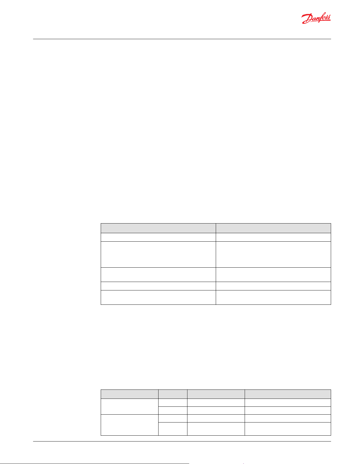
EM-PMI240-T180 options
Variant Code Description Additional information
Drive-end shaft * Male shaft DIN5480 W40x2x18x8f
+S2 Female spline ANSI B92.1B 14T 12/24
D-end attachment * Standard flange SAE 6, transmission housing
+DE1 Flange interface for
hydraulic pump
Four bolt, SAE C flange
©
Danfoss | July 2021 BC355256345493en-000201 | 5
Page 6
User Guide
EM-PMI240-T180 User Guide
General information
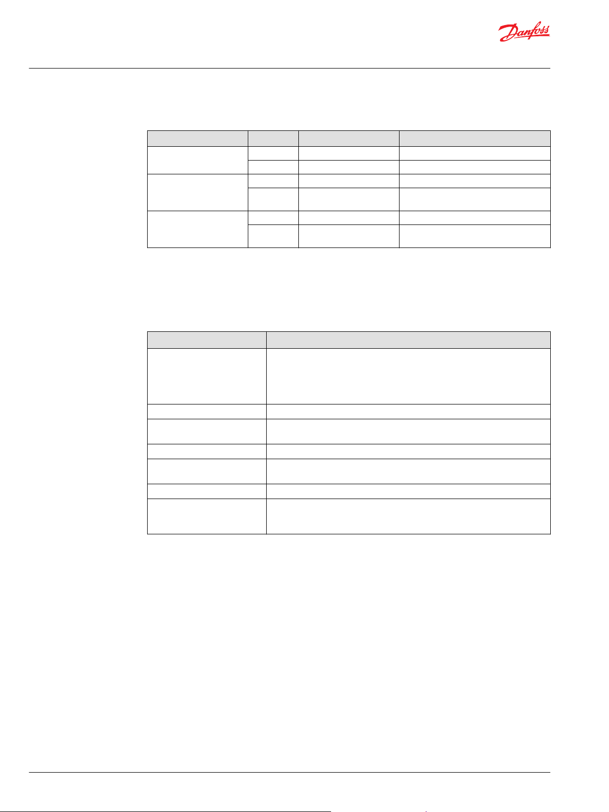
EM-PMI240-T180 options (continued)
Variant Code Description Additional information
Protection class * Standard protection class IP65 protection class
Rotation sensor (resolver) * None No resolver
Winding temperature
sensors
Conformity according to standards
The electric machine has been designed to be in conformity with the following directives and to meet the
requirements specified in the following standards:
Applicable Directives and standards
Standard Explanation
Low Voltage Directive
2006/95/EC (until 19.4.2016)
and Low Voltage Directive
2014/35/EU (from 20.4.2016
onwards)
IEC 60034-1:2010 Rotating electrical machines - Part 1: Rating and performance
IEC 60034-5:2001/A1:2007 Rotating electrical machines - Part 5: Degrees of protection provided by the
IEC 60034-6:1991 Rotating electrical machines - Part 6: Methods of cooling
IEC 60034-7:1992/A1:2001 Rotating electrical machines - Part 7: Classification of types of construction,
IEC 60034-8:2007/A1:2014 Rotating electrical machines - Part 8: Terminal markings and direction of rotation
IEC 60034-14:2004/A1:2008 Amendment 1 - Rotating electrical machines - Part 14: Mechanical vibration of
+IP67 IP67 protection class IP67 protection class
+RES1 Resolver In-built non contacting resolver, 4-pole
* Temperature surveillance 3 x PT100 (two wire) in windings
+TEMP4 Redundant temperature
surveillance
Electrical equipment means any equipment designed for use with a voltage
rating of between 50 and 1000 V for alternating current. This electric
machine is subject to the Low Voltage Directive 2006/95/EC or 2014/35/EC.
integral design of rotating electrical machines (IP code) - Classification
mounting arrangements and connection box position (IM Code)
certain machines with shaft heights 56 mm and higher - Measurement, evaluation
and limits of vibration severity.
pair
6 x PT100 (two wire) in windings (requires
+LVB1)
Warranty
Danfoss offers warranty against defects in workmanship and materials for its products for a period of
twelve (12) months from commissioning or eighteen months (18) from delivery (Incoterms-EXW),
whichever occurs first.
In order for the warranty to be valid, the customer must follow the requirements of this and all related
documents, especially those set out in the product installation and maintenance, as well as the applicable
standards and regulations in force in each country.
Defects arising from the improper or negligent use, operation, and/or installation of the equipment, nonexecution of regular preventive maintenance, as well as defects resulting from external factors or
equipment and components not supplied/recommended by Danfoss, will not be covered by the
warranty.
The warranty will not apply if the customer at its own discretion makes repairs and/or modifications to
the equipment without prior written consent from Danfoss.
Terms and abbreviations
The symbols, terms and abbreviations in the Tables below are possibly used in this manual.
6 | © Danfoss | July 2021 BC355256345493en-000201
Page 7
User Guide
EM-PMI240-T180 User Guide
General information
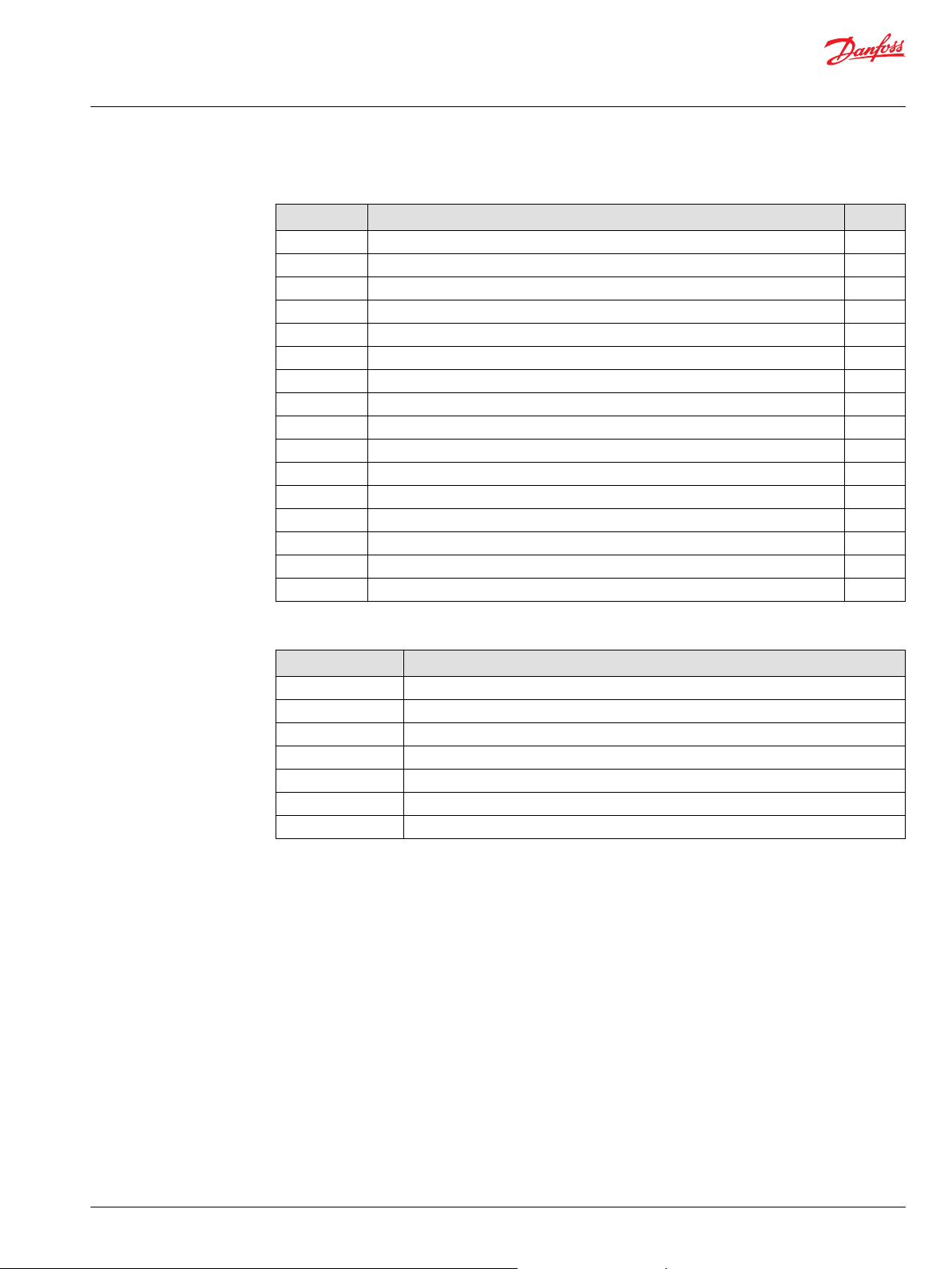
Symbols
Symbol Variable Unit
U Rated voltage (phase-to-phase AC) V
I Rated current (AC) A
P Rated Power (S1) kW
T Rated torque (S1) at rated speed Nm
T
max
n Rated speed rpm
Max n Maximum speed rpm
f Rated supply frequency at nominal speed Hz
PF Power factor (cosφ)
Q
c
T
c
T
amb
RES_COS Cosine signal received from the resolver deg
RES_SIN Sinusoidal signal received from the machine resolver deg
GND Ground in electrical connections
Ω (Ohm) Resistance Ω
rms
rms
Maximum torque Nm
Rated coolant liquid flow l/min
Rated coolant liquid input temperature °C
Rated ambient temperature °C
Term / abbreviation
Term/ Abbreviation Explanation
Resolver Rotation meter in electric machines, used for measuring degrees of rotation
AC Alternating current
DC Direct current
PMSM Permanent Magnet Synchronous Machine
SRPM Syncronous Reluctance assisted Permanent Magnet
S1 Duty type according to the IEC60034; Continuous running duty
S9 Duty type according to the IEC60034; Duty with non-periodic load and speed variations
Responsibility of the manufacturer
Danfoss is responsible for the safety, reliability and performance of the electric machine only if:
•
Handling, mounting, installation, operation and maintenance are done by qualified and authorized
personnel.
•
The installation of the system complies with the requirements of the appropriate regulations.
•
The electric machine is used in accordance with the instructions in this user guide.
•
The electric machine is installed, maintained and serviced in accordance with the instructions in this
user guide.
©
Danfoss | July 2021 BC355256345493en-000201 | 7
Page 8
User Guide
EM-PMI240-T180 User Guide
Safety information
General safety statement
•
•
•
•
•
Safety message signal words
Safety message signal words indicate the severity of a potential hazard.
DANGER Indicates an imminently hazardous situation which, if not avoided, will result in death or serious
injury.
WARNING Indicates a potentially hazardous situation which, if not avoided, could result in death or
serious injury.
CAUTION Indicates a potentially hazardous situation which, if not avoided, may result in minor or
moderate injury. CAUTION may also alert against unsafe practices.
NOTICE Indicates a potentially hazardous situation which, if not avoided, could result in property
damage.
The electric machine is intended for use as a component for industrial and commercial installations.
The end product containing the electric machine must conform with all related regulations.
The use of the electric machine is prohibited in hazardous areas unless it is expressly designed for
such use.
The electric machine is intended for installation, use and maintenance by qualified personnel, familiar
with health and safety requirements and national legislation. Ignoring these instructions may
invalidate all applicable warranties.
These instructions must be followed to make sure of safe and correct installation, operation and
maintenance of the electric machine. They should be brought to the attention of anyone who installs,
operates or maintains the electric machine or associated equipment.
High voltage and rotating parts can cause serious or fatal injuries. For electric machine covered by
this user guide, it is important to observe safety precautions to protect personnel from possible
injury.
Safety symbols
The following safety and information related symbols appear in this user guide and on the electric
machine.
Danger
This symbol is identified by a yellow background, red octagonal band and a black STOP text.
It indicates a hazardous situation that causes severe injury or death. Action indicated by this
symbol may not be executed.
General warning
This symbol is identified by a yellow background, black triangular band, and a black
exclamation point symbol. It indicates a general potentially hazardous situation.
Electric shock warning
The symbol is identified by a yellow background, black triangular band, and a black
arrowhead symbol. It indicates dangerous electrical voltage that could cause an electric shock
to a person.
Burn warning
The symbol is identified by a yellow background, black triangular band, and a black wavy
lines symbol. It indicates a hot device that could cause burns to a person.
The symbol also indicates that the device should be placed and installed so that contact with
its potentially hot surface is not possible.
8 | © Danfoss | July 2021 BC355256345493en-000201
Page 9
User Guide
EM-PMI240-T180 User Guide
Safety information
Magnet warning
The symbol is identified by a yellow background, black triangular band, and a black magnet
symbol. It indicates strong magnetic field that could cause harm to a person or property.
Rotating shaft warning
The symbol is identified by a yellow background, black triangular band, and a black rotating
shaft symbol. It indicates strong rotating shaft that could cause harm to a person or property.
General Information.
Read the instructions in the user guide.
Personal protective equipment
Personal protective equipment shall be used when necessary during handling, installation and
maintenance of the electric machine to avoid injury.
Use eye protective equipment like safety goggles or mask when you work with the electric
machine. Permanent damage to the eye could be caused if bearing grease, melted nitrile
rubber (radial lip seal), glycol or other fluids splash.
Use hearing protective equipment when you work on the electric machine. Hearing injuries
can be caused by too loud noise (noise in excess of 85 dBA).
Use head protective equipment like helmet when you lift the electric machine! Head injuries
can be caused by object impact.
Use cut resistant gloves when you handle and maintain the electric machine. There is a risk of
cut injuries.
Use protective footwear when you lift or move the electric machine! Foot injuries could be
caused if lifting system or lifting brackets fail.
Security features
The electric machine has at least one PT100 temperature sensor in the windings. The amount of the
sensors depend on the options chosen. The temperature signal(s) can be read out from the measurement
©
Danfoss | July 2021 BC355256345493en-000201 | 9
Page 10
User Guide
EM-PMI240-T180 User Guide
Safety information
connector of the electric machine. You can connect the temperature signal to the temperature
surveillance pin in the inverter (EC-C) and make sure that the inverter has the machine temperature
protection feature activated.
Electromagnetic compatibility (EMC)
EMC stands for Electromagnetic compatibility. It is the ability of electric equipment to operate without
problems within an electromagnetic environment. Likewise, the equipment must not disturb or interfere
with any other product or system within its locality. This is a legal requirement for all equipment taken
into service within the European Economic Area (EEA).
Our products are designed with high standards of EMC in mind. Connect the power lines and groundings
along the instructions in this user guide to achieve the required level of EMI protection.
It is the responsibility of the installer to make sure that the equipment or system into which the product is
incorporated complies with the EMC legislation of the country of use. Within the European Union,
equipment into which this product is incorporated must comply with the EMC Directive 2014/30/EU.
When interfacing other equipment, connect only equipment that are specified as part of the
system and that are compatible.
Magnetic and electromagnetic fields generated near the current-carrying conductors and
permanent magnets in electric machines represent a health danger to persons with heart
pacemakers, metal implants and hearing aids. Persons with a heart pacemaker, metal
implants or hearing aids must consult a doctor before they enter the following areas:
•
Areas in which electric equipment and parts are operated
•
Areas in which electric equipment with permanent magnets are stored, mounted,
operated or repaired
If necessary, perform a special electromagnetic compatibility (EMC) test on the installation.
10 | © Danfoss | July 2021 BC355256345493en-000201
Page 11
User Guide
EM-PMI240-T180 User Guide
Product overview
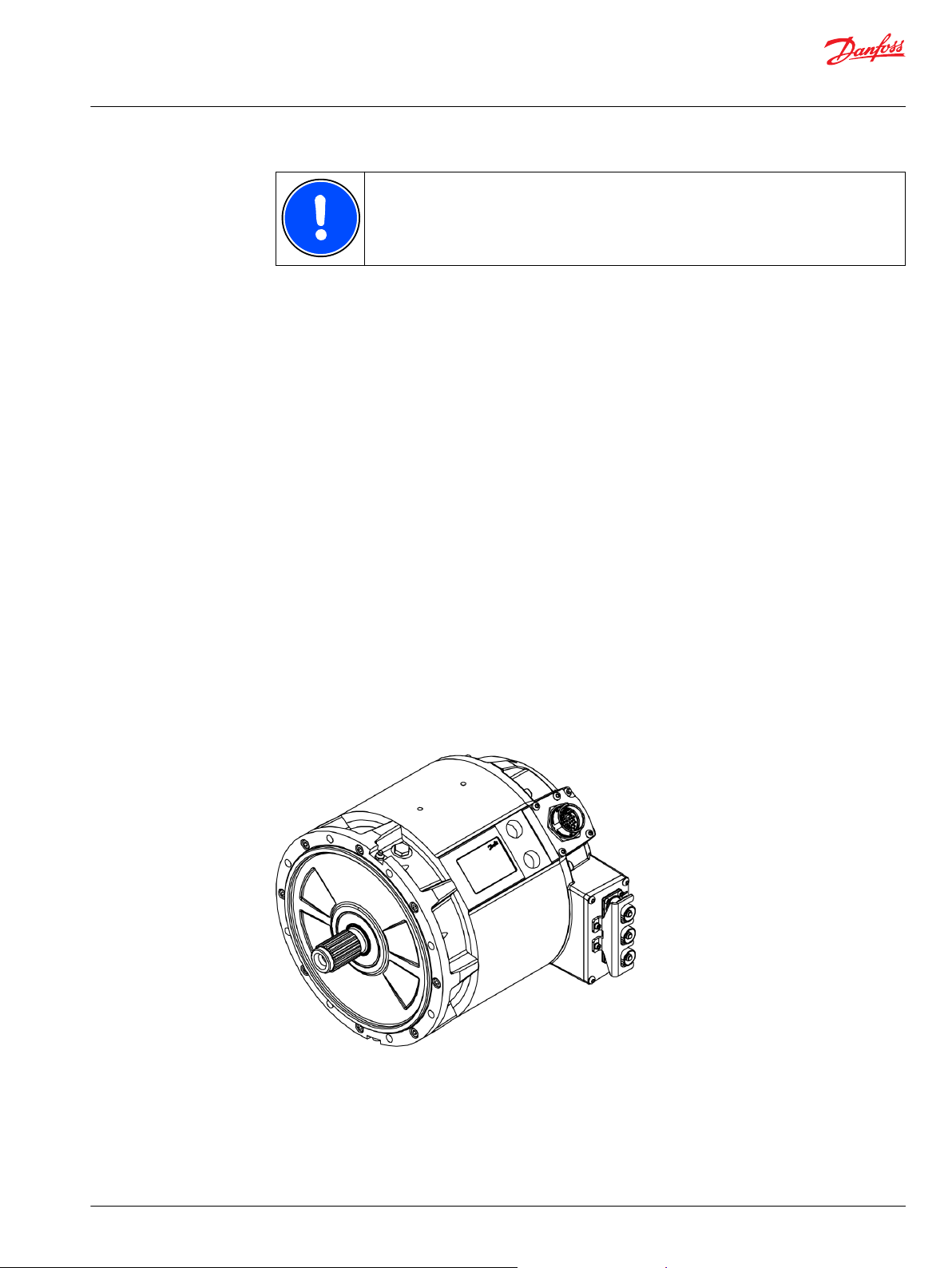
The electric machines have been developed especially for heavy duty, marine and transportation
applications. They are more reliable, smaller, lighter and more efficient than conventional products on
the market.
Typical applications of the electric machines are:
•
•
The electric machines feature Synchronous Reluctance assisted Permanent Magnet (SRPM) motor
technology, having several advanced features:
•
•
•
•
•
•
•
•
•
•
For harsh conditions, like salty air in marine applications, it is recommended to check the
surface treatment possibilities with the factory.
Motor (electric propulsion) and generator for hybrid marine vessels or mobile work machine and bus
parallel hybrid applications.
Traction motor and generator for electrical or hybrid electrical mobile work machines or buses.
Extremely compact and robust structure.
High efficiency throughout the operation range.
Liquid cooling with water/glycol mixture.
Low coolant flow required.
High allowed coolant temperature.
IP65 enclosure class to maximize reliability.
Multiple mounting possibilities.
Extended speed and torque capabilities compared to standard PM machines.
Machine structure designed to be able to produce high starting torques (instant torque to non-
moving wheel).
Optimized speed range to meet most common gear ratios used in heavy mobile machinery.
The electric machine
Intended use of the electric machine
This electric machine is intended to be used as a motor or generator and as a part of a machinery, for
example in:
©
Danfoss | July 2021 BC355256345493en-000201 | 11
Page 12

User Guide
EM-PMI240-T180 User Guide
Product overview
•
•
The electric machine is intended to be powered and controlled with an inverter or inverters capable of
supplying three-phase alternating current and that is capable of controlling the electric machine. The
electric machine is not suitable for direct online use.
In a power generation equipment the electric machines are intended to be powered by a prime mover,
for example, an internal combustion engine and controlled by the above mentioned electric power
inverter.
The electric machine is solely intended for professional use, and may be operated only by trained
professionals. The maintenance of the electric machine may be done only by trained professionals.
Forbidden use of the electric machine
It is forbidden to use, handle and maintain the machine in following ways (including but not limited to):
•
•
•
•
•
•
•
•
•
•
•
•
•
•
•
•
•
•
•
•
•
•
Power train of a marine vessel, transportation vehicle or a heavy duty work machine.
Power generation equipment.
Using the electric machine for other purposes than defined in this user guide.
Disregarding the obligation to comply with the user guide, safety signs and rating plate of the electric
machine.
Using the electric machine, making adjustments and maintenance without first reading this user
guide.
Exceeding the designed limits during the electric machine operation.
Using non-original service parts of wrong material causing corrosion problems and mechanical
failures in time.
Operating and performing maintenance for the electric machine without appropriate personal
protective equipment.
Using electric machine parts like frame, shaft end or terminal box for climbing or for support for other
structures.
Causing any kind of impact forces to the electric machine (for example hitting or hammering or
dropping objects).
Operating the electric machine with electric connections other than defined in the user guide and/or
other documents.
Operating the electric machine with insufficiently tightened connections or cable glands.
Operating the electric machine with power cables routed against the instructions.
Operating the electric machine without properly dimensioned and operating cooling system.
Operating the electric machine without following the bearing lubrication instructions.
Touching the connection terminal of the electric machine or doing maintenance or adjustment
operations on the electric machine with the electricity connected.
Accessing the connection box(es) if the shaft can be turned by an external prime mover.
Lifting the electric machine from wrong lifting points and without correct lifting equipment.
Lifting additional load with the machine.
Storing the electric machine outdoors in wet or dusty conditions.
Storing the electric machine without correct support to prevent rolling or falling of the machines.
Using the electric machine in potentially explosive environment.
Allowing dirt or liquid to enter into the electric machine or connection box.
Using cables that cannot withstand the maximum currents of the electric machine.
Used technology
The electric machine is a Synchronous Reluctance assisted Permanent Magnet (SRPM) machine. This
technology has several benefits compared to standard permanent magnet (PM) technology and
traditional induction machine (IM) technology. The SRPM technology combines the benefits of PM and
Synchronous Reluctance technology, having increased torque capability over wide speed range and
ability to produce torque to higher speeds. The electric machine efficiency at lower speeds is also good.
12 | © Danfoss | July 2021 BC355256345493en-000201
Page 13
User Guide
EM-PMI240-T180 User Guide
Product overview
The supply current to the machine stator windings create rotating magnetic field, which in turn rotates
the rotor containing permanent magnets. In the synchronous permanent magnet machine, the rotation
of the rotor (shaft) is synchronized with the frequency of the power supply current. The reluctance
technology maximizes the pull-out torque of the machine.
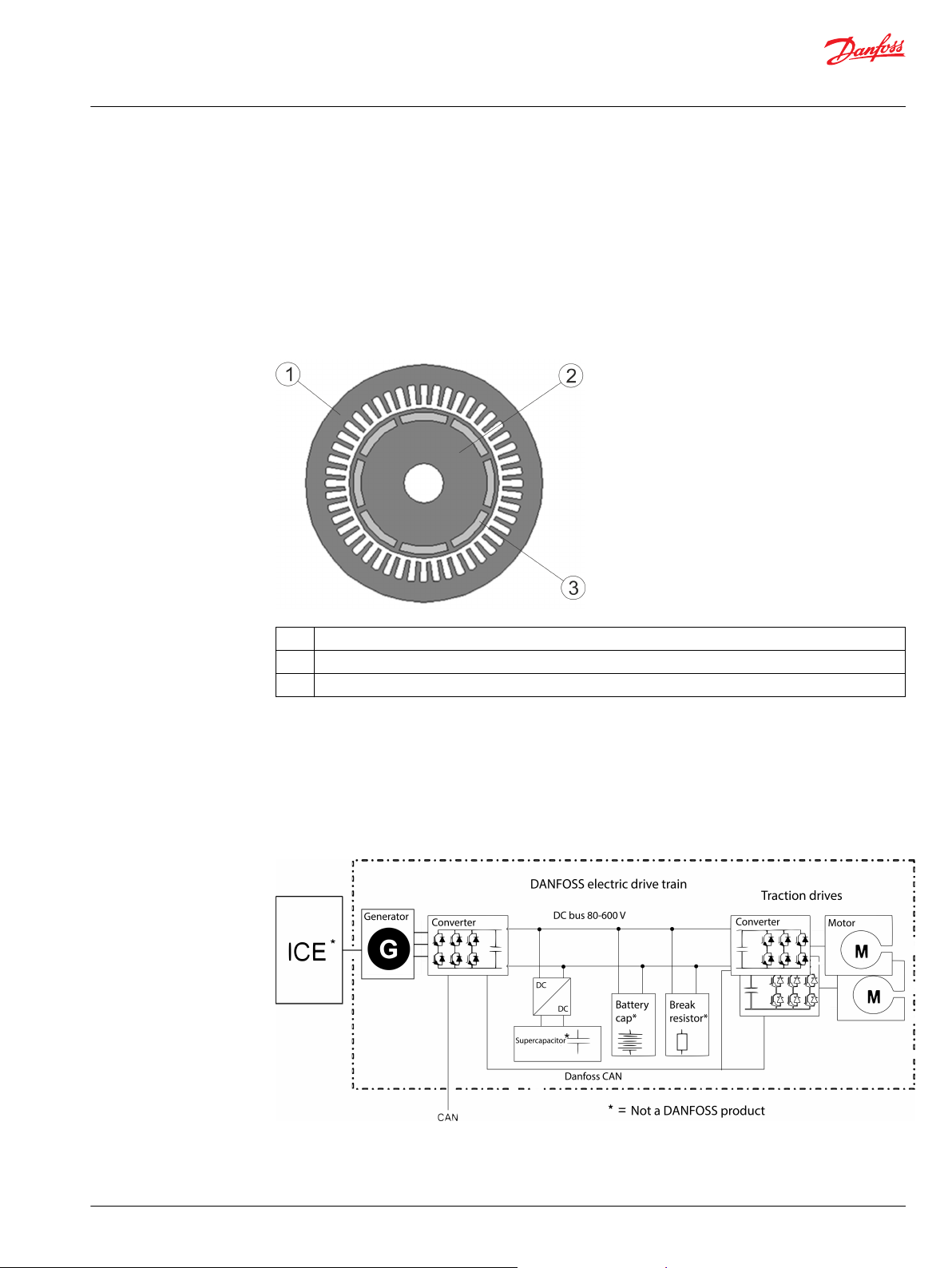
The permanent magnets of the rotor are of salient-pole design, having embedded permanent magnets in
the rotor structure. This structure makes the electric machine mechanically more stable and capable of
higher speed operations. See Figure below illustrating the magnet topology of the electric machine. The
Figure shows the principle only, and is not an exact illustration of the structure.
Machine topology
System introduction
1 Electric machine stator and stator windings
2 Electric machine rotor
3 Permanent magnets in the rotor
Danfoss provides electric drive trains for applications in heavy mobile work machines, marine vessels and
buses. The drive trains include all essential components from converting from traditional to hybrid
electric (HEV) or electric vehicle (EV) solutions. Danfoss technology saves fuel and lowers emission and
noise levels.
Overview of the Danfoss drive train system
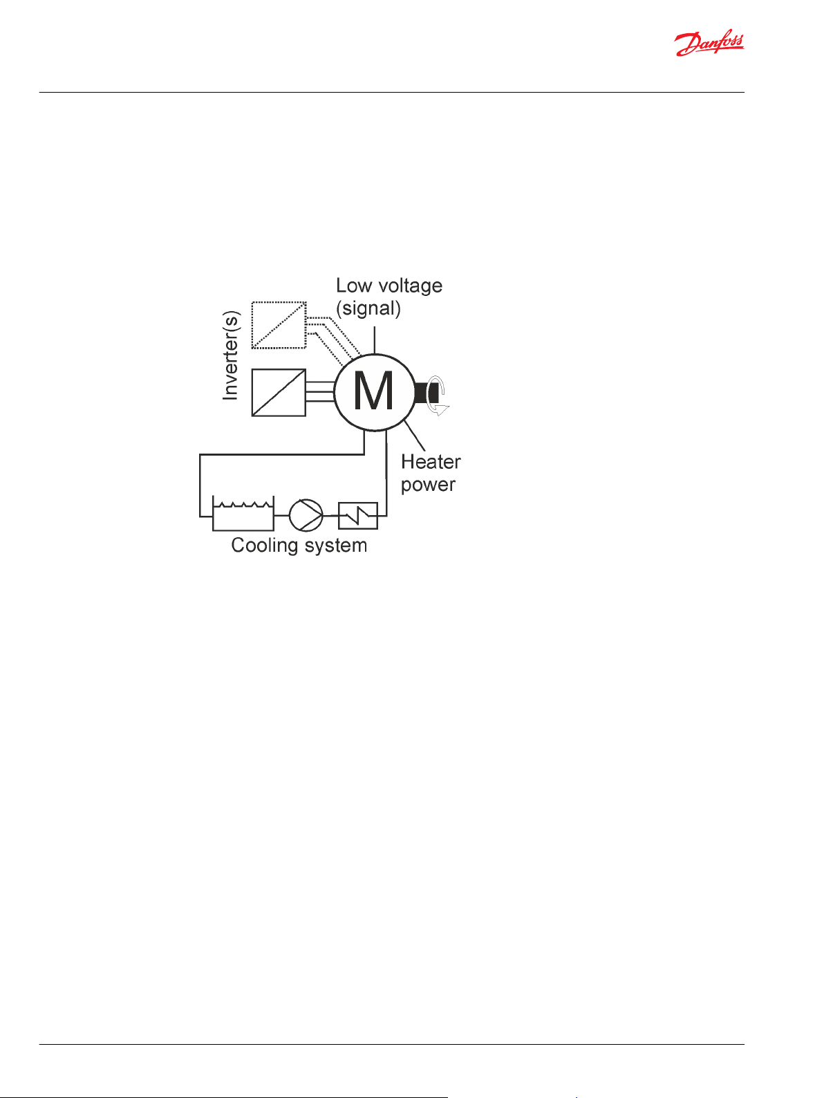
The electric machines are liquid cooled with water/glycol mixture. For more information, see
Chapter Cooling connections.
©
Danfoss | July 2021 BC355256345493en-000201 | 13
Page 14
User Guide
EM-PMI240-T180 User Guide
Product overview
A low voltage measurement signal connector is attached to the electric machines. Different temperature
and resolver signals can be read, depending on the machine options chosen. For more information about
the connection, see Chapter Low voltage connections.
The electric machines (some models) can be equipped with one or two anti-condensations heater(s),
depending on the machine type and the option chosen. The heater is used to prevent any water
condensing inside the machine enclosure.
Overview of electric machine system
Connections and interfaces
The electric machines are connected mechanically and electrically as a part of a machinery or as a part of
a power generation equipment.
Mechanical interfaces:
Lifting points.
•
Flange mounting (D-end and N-end).
•
Shaft connection(s).
•
Cooling system connections (bores).
•
Grease escape/fill connections; depending on model and option (BHS): maintenance use only.
•
Air ventilation plug.
•
Electrical interfaces:
Power connections.
•
Measurement connections.
•
Low voltage (measurement signal) grounding connection.
•
Power grounding connection.
•
14 | © Danfoss | July 2021 BC355256345493en-000201
Page 15
User Guide
EM-PMI240-T180 User Guide
Product overview
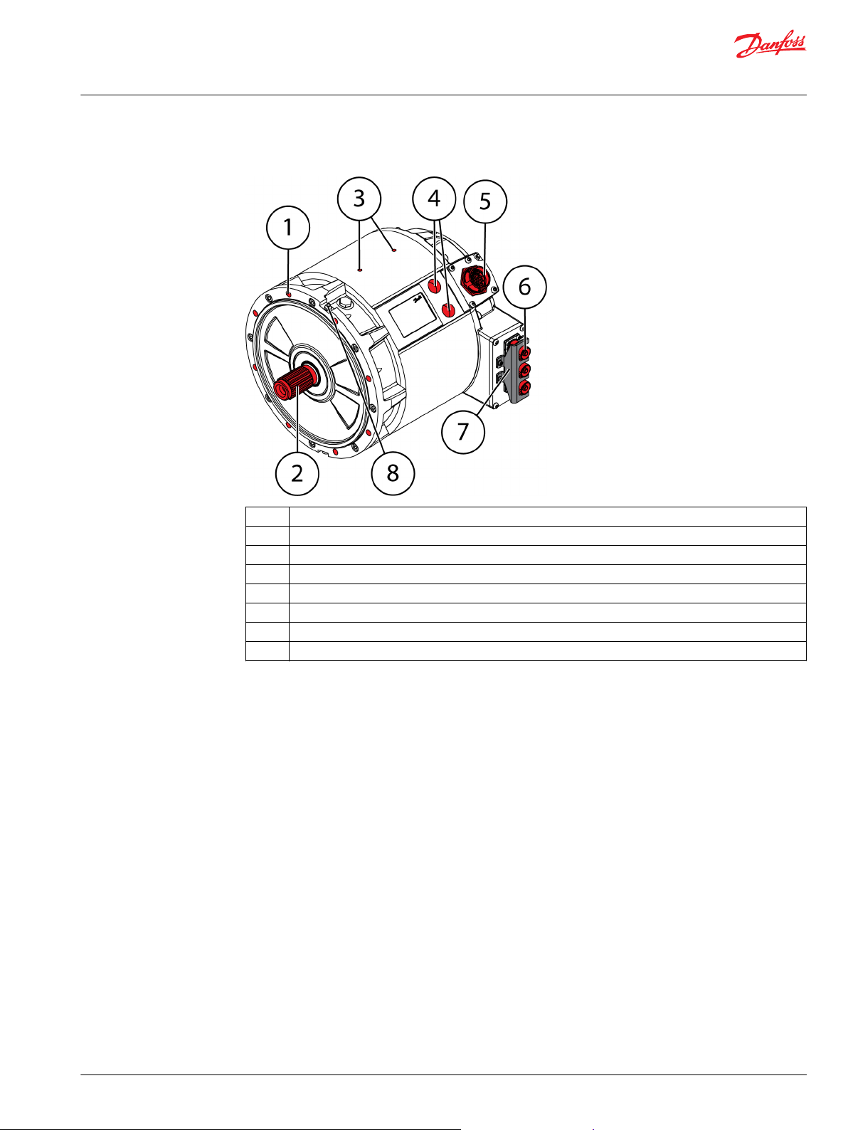
Connections and interfaces
Rating plate
1 D-end mounting holes, 8 pcs (diameter 11 - THRU)
2 Shaft connection DIN5480 Spline W40x2x18x8f
3 Lifting holes, 2 pcs. M8x1.25 (15 mm deep). They can be used for grounding.
4 Cooling liquid bores G 3/4
5 Low voltage connector DEUTSCH HD34-24-47PE
6 Phase connections AMPHENOL HVBI005R10AMHARD
7 Connector locking plate (mechanical safety feature)
8 Bearing grease nipple - option dependent (both bearings have one)
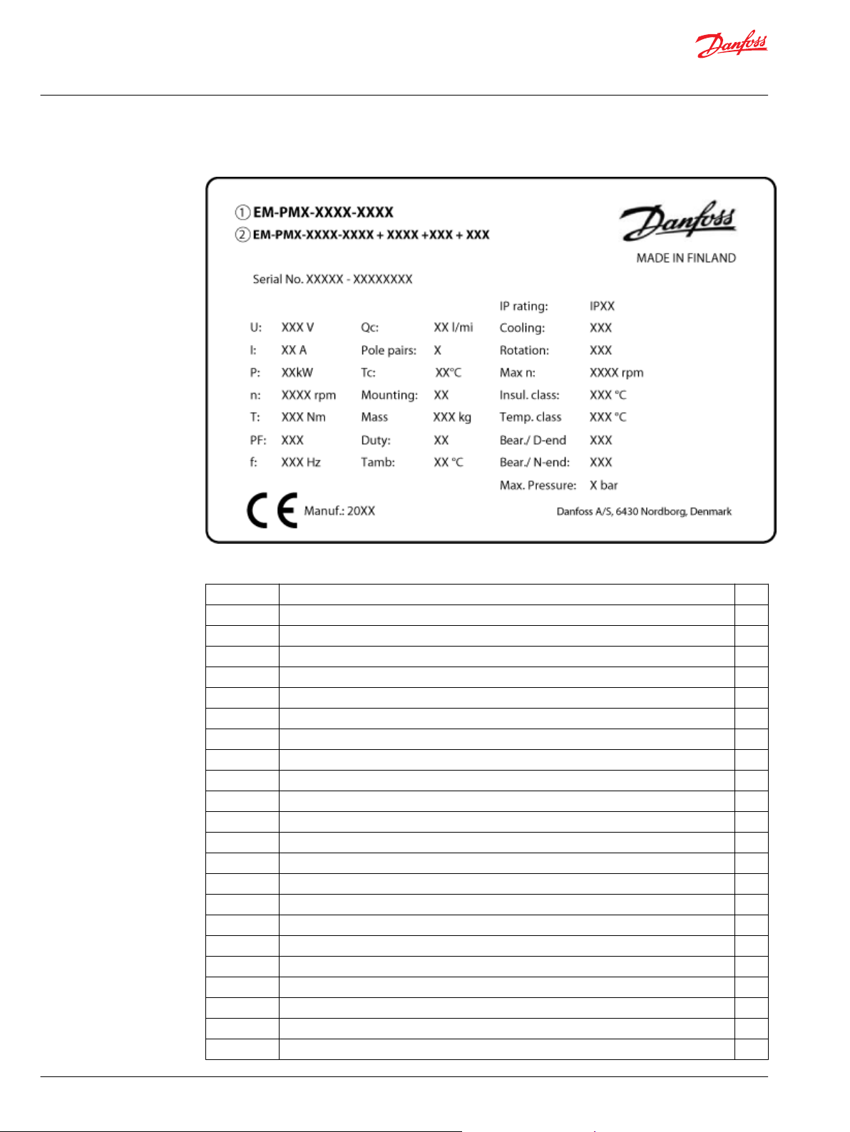
Each electric machine has a rating plate which can be found on the machine frame. The rating plate
contains machine rating and identification. The rating values in the Figure below are not correct for this
machine. See the rating plate on the machine and data sheets for the correct values.
©
Danfoss | July 2021 BC355256345493en-000201 | 15
Page 16
User Guide
EM-PMI240-T180 User Guide
Product overview
Rating plate
Rating plate fields
Field Explanation Unit
1 Electric machine product family: EM-PMI or EM-PME
2 Electric machine type code and options
Serial No. Serial number
U Rated voltage V
I Rated current (AC) I
P Rated power (S9) according to IEC60034-1 kW
n Rated speed rpm
T Rated torque (S9) at rated speed Nm
PF Power factor
f Rated supply frequency at nominal speed Hz
Q
c
Pole pairs Number of magnetic pole pairs of the machine
T
c
Mounting Allowed mounting position according to IEC60034-7
Mass Mass of the electric machine kg
Duty Defined rotating electric machine duty cycles by IEC60034-1 standard
T
amb
IP rating Enclosure class according to IEC60034-5
Cooling Cooling method according to IEC60034-6
Rotation Direction of rotor rotation with default phase order. Observed facing the D-end.
Max n Maximum rotation speed rpm
Insul. class Temperature rating (class) of insulation of the electric machine according to IEC60034-1
Rated coolant liquid flow l/min
Rated coolant liquid input temperature °C
Rated ambient temperature °C
rms
rms
16 | © Danfoss | July 2021 BC355256345493en-000201
Page 17
User Guide
EM-PMI240-T180 User Guide
Product overview
Rating plate fields (continued)
Temp. class Temperature rating (class) of individual insulation materials of the insulation according to
Bear. / D-end Bearing type (types) in the D-end of the electric machine
Bear. / N-end Bearing type in the N-end of the electric machine
Max. pressure Cooling liquid max pressure
CE Depending on the details of the delivery, the rating plate might not have CE-marking
Tightening torques
IEC60034-1
Tightening torque tolerance is +/- 5% of the specified tightening torque.
Use threadlocking adhesive for RST bolts.
Do not install dry screws or other fastening equipment.
Add suitable lubrication, for example Wuerth HSP 1400, to prevent excess friction.
Tightening torques to use unless otherwise noted
8.8 10.9 12.9
Thread Nm Nm Nm
M5 7 10 11
M6 11 17 19
M8 27 40 47
M10 54 79 93
M12 93 137 160
M14 148 218 255
M16 230 338 395
©
Danfoss | July 2021 BC355256345493en-000201 | 17
Page 18
User Guide
EM-PMI240-T180 User Guide
Design principles
This Chapter describes design principles that must be taken into account when designing the system
using the electric machine.
System design
Cooling and temperature measurement
Do not operate the electric machine without correctly dimensioned and operating cooling
system.
Mount the electric machine in correct position, see Chapter Allowed mounting position.
When you connect the cooling system make sure that the cooling medium flows freely in and
out from the electric machine with the cooling medium flow equal or higher than rated.
The cooling medium temperature at the inlet of the electric machine must be lower or equal
to the rated temperature.
See more detailed information about coolant connection bore specifications, required coolant liquid flow
and other specifications in the product data sheet. Rated values can be found from the electric machine
rating plate.
The electric machine has at least one PT100 temperature sensor in the windings. The amount of the
sensors depend on the options chosen. The temperature signal(s) can be read out from the measurement
connector of the machine.
The maximum allowed winding temperature of the electric machine is shown in the rating plate and in
the data sheet.
The PT100 temperature sensor characteristics are: resistance 100 Ω at 0 ºC temperature, and the
resistance increases 0.385 Ω per each 1 ºC increase of temperature.
Insulation lifetime
Heat cycles, environment, moisture, vibrations and similar variables have an effect on the
lifetime expectancy of the insulation of the electric machine. The value of the insulation
lifetime expectancy is a calculated value and it is not tested in practice.
The insulation of the electric machine has the following lifetime expectancy.
Insulation class Lifetime expectancy
F (150°C) 20 000 h
H (175°C) 20 000 h
100 000 h if driven with maximum winding temperature of 150°C
18 | © Danfoss | July 2021 BC355256345493en-000201
Page 19

User Guide
EM-PMI240-T180 User Guide
Design principles
Inverter
The electric machine is intended to be powered and controlled with an inverter capable of supplying
three-phase alternating current and that is capable of controlling the electric machine. The electric
machine is not suitable for direct online use.
If the electric machine is driven with an inverter from a supplier other than Danfoss Editron, the electric
machine performance may differ from rated values. The optimum performance of the electric machine is
obtained with Danfoss Editron inverters. These inverters are:
•
•
•
•
•
EC-C1200
Compact and light.
Liquid cooled.
Tolerant to high mechanical vibration (10 G) and shock (50 G).
Efficient, efficiency > 98 %.
Reliable, no moving components.
Do not exceed the maximum rotation speed of the electric machine.
©
Danfoss | July 2021 BC355256345493en-000201 | 19
Page 20

L1
L2
U
V
W
-
-
L3
DC +
+
+
DC -
AUX DC +
AUX DC -
User Guide
EM-PMI240-T180 User Guide
Design principles
Schematic of the inverter powerstage
Mounting structure
The main machine power driving parameters are shown in the machine rating plate. For more
information, contact Danfoss representative.
You can connect one of the temperature signals (from the low voltage connector) to the temperature
surveillance pin in the inverter and make sure that the inverter has the machine temperature protection
feature activated.
Supporting structure requirements
Do not install the electric machine near or in direct contact with easily flammable materials.
The surface of the electric machine can be hot.
The mating housing arrangement of the electric machine must be secure and sufficiently rigid to prevent
vibrations and mechanical failures. Necessary actions should be taken to avoid corrosion on the mating
housing arrangement.
The supporting structure for the electric machine must be such that the electric machine can be
mounted using its allowed mounting positions, see Chapter Allowed mounting positions.
The mounting space must be adequate for the electric machine mounting and possible auxiliary
components. See the length and the diameter data of the electric machine from the product drawing.
Main dimensions of the electric machine are shown in the Figure below (the illustration may differ from
the actual electric machine).
20 | © Danfoss | July 2021 BC355256345493en-000201
Page 21

User Guide
EM-PMI240-T180 User Guide
Design principles
Main dimensions of the electric machine
Symbol Explanation
L
F
L
S
D
M
D
S
Length of the electric machine frame (including the connection box(es).
Length of the shaft (from the end of the shaft to the electric machine D-end mounting shoulder).
Diameter of the flange mounting bore circle.
Diameter of the mounting shoulder.
For all dimensions of the electric machine, see the product drawings.
Shaft alignment and load
Improper alignment (misalignment) may result in bearing overloads, premature bearing
failures, vibrations and shaft failures. Flexible coupling does not compensate for excessive
misalignment.
The type of electric machine shaft is DIN5480 SplineW40x2x18x8f. Recommended female connection
counterpart is of type SAE 6 Mating transmission housing flange.
Alignment between the shaft and mating structure must be accurate.
The misalignment can be parallel or angular misalignment, or combination of those. With parallel
misalignment, the center lines of both shafts are parallel but they are offset. With angular misalignment,
the shafts are at an angle to each other. Figures below illustrate the parallel and angular misalignment.
©
Danfoss | July 2021 BC355256345493en-000201 | 21
Page 22

User Guide
EM-PMI240-T180 User Guide
Design principles
Parallel alignment of the shaft and mating structure
Maximum parallel misalignment values
rpm mm mm
0-1000 0,07 0,13
1000-2000 0,05 0,10
2000-3000 0,03 0,07
3000-4000 0,02 0,05
4000-6000 < 0,02 0,03
Non flexible coupling Flexible coupling
Angular alignment of the shaft and mating structure
Maximum angular misalignment values
Non flexible coupling Flexible coupling
rpm mm / 100 mm mm / 100 mm
0-1000 0,06 0,10
1000-2000 0,05 0,08
2000-3000 0,04 0,07
3000-4000 0,03 0,06
4000-6000 < 0,03 0,05
22 | © Danfoss | July 2021 BC355256345493en-000201
Page 23

User Guide
EM-PMI240-T180 User Guide
Design principles
External shaft forces of the electric machine
The maximum external force directed to the shaft axially and radially may not exceed
machine specific values. For more information, see document DOC-000454. Calculate the
relevant values with the help of the document.
Contact Danfoss service at https://danfosseditron.zendesk.com/hc/en-gb or send email to
editron.service@danfoss.com to obtain the document.
©
Danfoss | July 2021 BC355256345493en-000201 | 23
Page 24

User Guide
EM-PMI240-T180 User Guide
Transportation and storage
Transportation
Electric machine is shipped in first class condition. It has been inspected and packed correctly to prevent
damage from ordinary handling during shipment. During transportation, shocks, fails and humidity
should be avoided. Protect the cooling holes for transportation.
The weight of the electric machine can be found on the machine rating plate, and in the product data
sheet.
Receiving and unpacking
Heavy equipment. Handle with care during transportation.
Do not touch the electric machine during the insulation resistance check. Discharge the
electric machine afterwards.
Lifting
Do not touch the electrical terminals when the rotor is rotated. The electrical terminals have
dangerous voltage during rotation. Contact Danfoss representative if the rotor can not be
rotated.
Remove the transportation supports of the electric machine.
Check upon arrival and unpacking
•
The electric machine and the package must be inspected immediately upon arrival. Make sure that
the rating plate data in the cover letter complies with the purchase order. Any external damage (in
shaft-ends, flanges, electrical interfaces and paint) must be photographed and reported immediately.
•
It is recommended to measure the insulation resistance of the electric machine upon arrival, or before
installing the electric machine. Reference value of 150 MΩ shall be exceeded in room temperature,
otherwise contact Danfoss representative. Refer to Chapter Insulation resistance test on page 29.
•
Remove any shaft locks and rotate the shaft. It is normal for the rotation of the shaft to be difficult.
Use correct, adequately dimensioned lifting devices and inspect them before lifting.
Do not lift from the shaft of the electric machine!
24 | © Danfoss | July 2021 BC355256345493en-000201
Page 25

User Guide
EM-PMI240-T180 User Guide
Transportation and storage
Do not apply any excess weight on the electric machine when lifting.
Use correct lifting slings. Use correct position and angle of lifting.
See the electric machine rating plate for weight information.
Lift the electric machine using the correct lifting lugs/eyes only.
Do not go under a lifted load.
Lifting slings cannot touch the electric machine during the lifting.
Lifting lugs/eyes/points for lifting slings and lifting position of the electric machine
Lifting eye type: RS M8 0,20t (2 pcs)
©
Danfoss | July 2021 BC355256345493en-000201 | 25
Page 26
User Guide
EM-PMI240-T180 User Guide
Transportation and storage
Horizontal lifting
Install 2 pieces of lifting eyes to the lifting bores of the electric machine frame. Mount the lifting eyes with
their full threaded length.
Vertical lifting
Vertical lifting
Do not let the lifting slings to touch the electric machine while lifting. Lifting slings may cause
damage to the electric machine.
Storage
1 Codipro DSR M 8 UP or equivalent of dimensions and load capacity.
Use swivel type M8 lifting rings with sufficient rated capacity to each loading direction. Refer to the lifting
ring manufacturer's instructions when attaching lifting rings to machine. It is important that lifting rings
are properly tightened in place.
Do not touch the electrical terminals when the shaft is rotated. The electrical terminals have
dangerous voltage during rotation.
Keep the electric machine on a correct base. Support the electric machine to prevent
accidental turning and falling.
Store the electric machine always indoors with the storage temperature above -20 ºC and the relative
•
humidity less than 60 %.
The storage should be dry, dust free and vibration free.
•
Treat the unprotected electric machine surfaces such as the shaft-end and flanges against corrosion.
•
Seal the cable exit holes and cooling bores for storage.
26 | © Danfoss | July 2021 BC355256345493en-000201
Page 27

User Guide
EM-PMI240-T180 User Guide
Transportation and storage
•
•
•
Extended storage
Electric machines equipped with relubricable bearings: apply grease before and after long term storage.
It is recommended to inspect the electric machine in storage at periodic intervals. Use attached storage
checklist.
Rotate the shaft of the electric machine once a month.
Keep the electric machine in its installation position while in storage. For example, vertically installed
electric machines should be stored in vertical position.
The electric machine must not be subject to any external vibrations during storage to avoid damage
to the bearings.
Use anti-condensation heaters, if fitted, or direct winding heating to avoid water condensing in the
electric machine.
Rotate the shaft of the electric machine by hand monthly at least ten revolutions to prevent grease
migration. If necessary, use a tool, for example a spanner. Do not damage the shaft in any case.
©
Danfoss | July 2021 BC355256345493en-000201 | 27
Page 28
User Guide
EM-PMI240-T180 User Guide
Installation
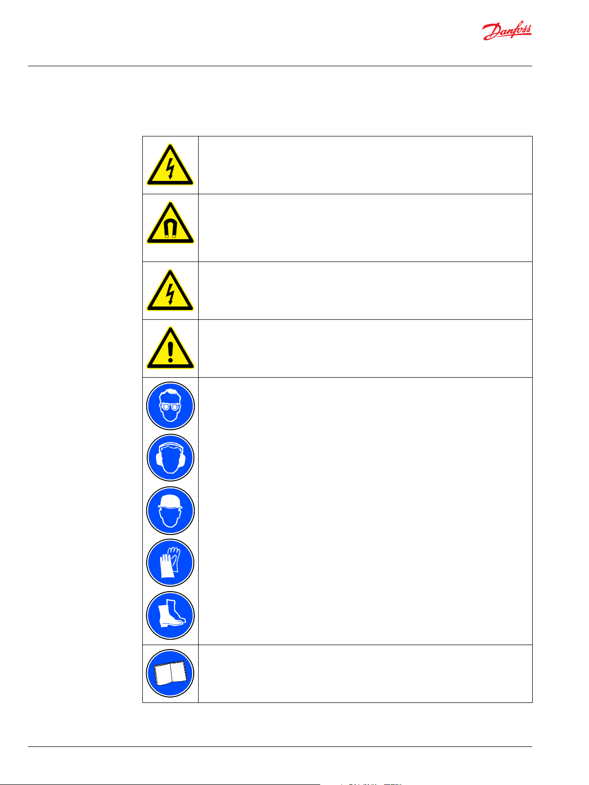
The following safety and information related symbols appear in this user guide and on the electric
machine.
Risk of electric shock when the connection box is open. When you work with power
connections make sure that electricity is disconnected and rotor rotation is prevented.
Magnetic and electromagnetic fields generated near the current-carrying conductors and
permanent magnets in electric machines represent a health danger to persons with heart
pacemakers, metal implants and hearing aids. Persons with a heart pacemaker, metal
implants or hearing aids must consult a doctor before they enter the following areas:
•
Areas in which electric equipment and parts are operated.
•
Areas in which electric equipment with permanent magnets are stored, mounted, operated
or repaired.
Risk of electric shock when working with the electric machine. Use isolated electric tools.
Only trained and qualified personnel familiar with the relevant safety requirements can work
with the electric machine.
Use correct personal protective equipment when you are near the electric machine.
Read the instructions in this user guide before you install the electric machine.
28 | © Danfoss | July 2021 BC355256345493en-000201
Page 29

User Guide
EM-PMI240-T180 User Guide
Installation
Required tools
Following tools are required to install the electric machine:
•
•
•
•
•
•
•
•
•
Insulation resistance test
Grease pump.
Ratchet torque wrench.
Hex head wrench kit with different metric sizes.
Socket wrench kit with different metric sizes.
Cable gland tightening tool. Size according to cable glands.
Cable skinning knife.
Crimping tool for cable lugs. Consult cable lug manufacturer for correct size.
Lifting slings with sufficient rated capacity.
Lifting eyes. Size according to machine type. See Chapter Lifting on page 24.
Do not touch the electric machine during the insulation resistance check. Discharge the
electric machine afterwards.
Mechanical installation
Measure the insulation resistance of the electric machine before and after the installation of
the electric machine.
Use a voltage of 500 V in the insulation resistance test.
Measure the insulation resistance of the electric machine before and after the installation of the electric
machine. Because of the structure of the electric machine, it is possible that the stator is damaged during
the installation.
If the electric machine is in continuous use, it is recommended to do the insulation resistance test three
or four times a year.
The reference value of 150 MΩ must be exceeded in room temperature. Contact Danfoss representative if
the reference value is not exceeded. Reference value of 150 MΩ should not be exceeded at reference
ambient temperature 25°C (measured with 500 VDC / 1 min Megger).
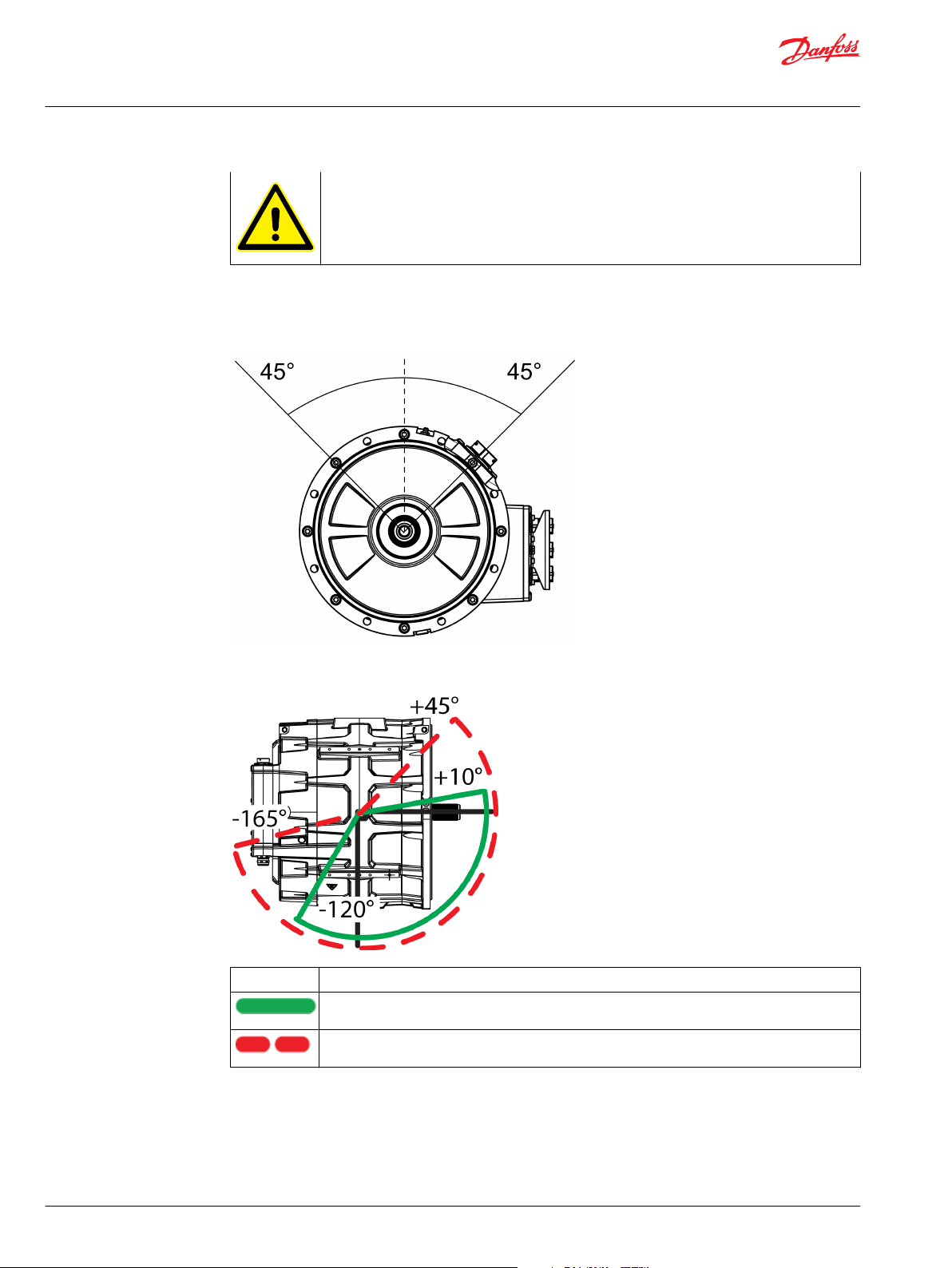
Allowed mounting positions
If the application is a moving work machine or similar, it is allowed to deviate from the
allowed mounting position for the duration of 30% of the work cycle. This applies to electric
machines with grease lubricated bearings.
©
Danfoss | July 2021 BC355256345493en-000201 | 29
Page 30
User Guide
EM-PMI240-T180 User Guide
Installation
The electric machine can be installed horizontally or vertically. See Figures below for the
allowed installation angles in each case.
Nominal allowed horizontal mounting position of the electric machine
It is in some cases possible to make an exception from the limitations of the mounting
positions. Document Allowed bearing loads for EM-PMI machines DOC-000454 gives more
information about this. Contact Danfoss to obtain the document.
Allowed deviations from the horizontal mounting limitations
Line type Meaning
Allowed deviations from the horizontal mounting limitations, continuous operation. (Depicted from
the shaft end.)
Allowed deviations from the horizontal mounting limitations, for the maximum duration of 30% of
the work cycle. (Depicted from the shaft end.)
30 | © Danfoss | July 2021 BC355256345493en-000201
Page 31
User Guide
EM-PMI240-T180 User Guide
Installation
Mounting the electric machine
Mount the electric machine on a correct supporting structure as discussed in Chapter Supporting structure
requirements.
Horizontal assembly
1. Lift the electric machine to the correct mounting position. See Chapter Lifting for details.
2. The electric machine is mounted from its D-end flange (SAE6 transmission housing flange). SAE6
flywheel housing is required as a mating flange.
3. Align the electric machine with the mating housing alignment. See Chapter Shaft alignment and load.
4. Connect the shaft of the electric machine, make sure to use full spline engagement. Lubricate the
spline.
Do not exceed the maximum axial and radial forces calculated for the shaft.
Document Allowed bearing loads for EM-PMI machines DOC-000454 gives more
information about this. Contact Danfoss to obtain the document.
Do not use the N-end of the electric machine for mounting the electric machine.
Refer to Chapter Allowed mounting positions for the correct mounting positions of the electric
machine.
A recommended spline lubricant is a 50/50 compound of a high temperature grease and a
molybdenum disulphide powder. When applied initially and re-applied at proper intervals, it
will help prevent fretting corrosion and premature wear. This lubricant is not soluble in oil
and should be used accordingly. Further products which may be recommended are Molycote,
Metaflux, Never Seeze, Optimol and similar.
5. Attach the mounting bolts. For steel housing the minimum length of the bolt is 40 mm and for
aluminum housing 45 mm.
©
Danfoss | July 2021 BC355256345493en-000201 | 31
Page 32

User Guide
EM-PMI240-T180 User Guide
Installation
Mechanical mounting connections of the electric machine (horizontal mounting)
1 D-end flange (SAE 6) with mounting holes
2 Shaft connection DIN5480 Spline W40x2x18x8f
3 Lifting points M8x1.25 (15 mm deep).
Cooling connections
Make sure that cooling liquid runs freely into and out from the electric machine.
To prevent damage to the cooling connectors, refer to the documentation of the
manufacturer for the correct tightening torque of the cooling liquid nipples.
When selecting cooling liquid nipples, choose nipples that can resist galvanic corrosion.
Connect the electric machine properly to the cooling circuit. Make sure that the coolant flow is equal or
higher than rated and the coolant temperature at the inlet of the machine cooling is lower or equal to the
rated temperature. For more information, see Chapter Recommended coolants and product data sheet.
Rated values can be found in the electric machine rating plate.
Aluminum frame water-cooled construction is only to be used with a closed fresh water circulation with
corrosive inhibitor described in the data sheet. The water cooling circuit connection is described in the
data sheet. Use only suitable and high-class connection parts and seals to connect the electric machine to
the water circuit. Check for possible leaks after the piping and joints have been connected.
Use only suitable and high-class connection parts and seals to connect the electric machine to the water
circuit. Check for possible leaks after the piping and joints have been connected.
It is recommended to use coolant connector equipped with o-ring seal or to use sealing washer (for
example Usit or Bonded seals) in the connection. In addition, it is recommended to use thread sealant
32 | © Danfoss | July 2021 BC355256345493en-000201
Page 33

User Guide
EM-PMI240-T180 User Guide
Installation
(Loctite 577 or similar) at the coolant connections to prevent loosening. Loosening can be caused by
vibration or temperature variations.
The electric machines are equipped with at least three PT100 temperature sensors in the windings. The
amount of the sensors depend on the options chosen. The temperature signal(s) can be read out from
the measurement connector of the machine.
Electrical installation
Power connections
High voltage connection
Risk of electric shock. When you work with power connections make sure that electricity is
disconnected and that the rotation of the rotor is prevented.
Mating connectors of the high voltage cables are not part of a standard delivery.
The order of the phases is marked on the power terminal with stickers.
High voltage connection
1 Power terminal
Connector type: AMPHENOL HVBI005R10AMHARD
Mating connector: AMPHENOL HVBI-7-05R10-XFC-XXXX-FG/PC (straight plug)
Installing the high voltage cables
©
Danfoss | July 2021 BC355256345493en-000201 | 33
Page 34

User Guide
EM-PMI240-T180 User Guide
Installation
1. Remove the connector locking plate. See the Figure below.
2. Install the high voltage cables. Refer to the instructions of the manufacturer of the mating
3. Install the connector locking plate back.
Connector locking plate
connectors.
1 Fasteners
2 Connector locking plate
Connection diagram
The electric machines are intended to be powered and controlled by three-phase alternating current,
supplied by an inverter or inverters. The electric machine is not suitable for direct online use.
The amount of inverters depends on the electric machine and converter current ratings.
For an electric machine with option SINGLE (one connection box containing one three-phase system), the
electrical connection principle from the inverter is shown in the Figure below.
Connection diagram for SINGLE option
34 | © Danfoss | July 2021 BC355256345493en-000201
Page 35

User Guide
EM-PMI240-T180 User Guide
Installation
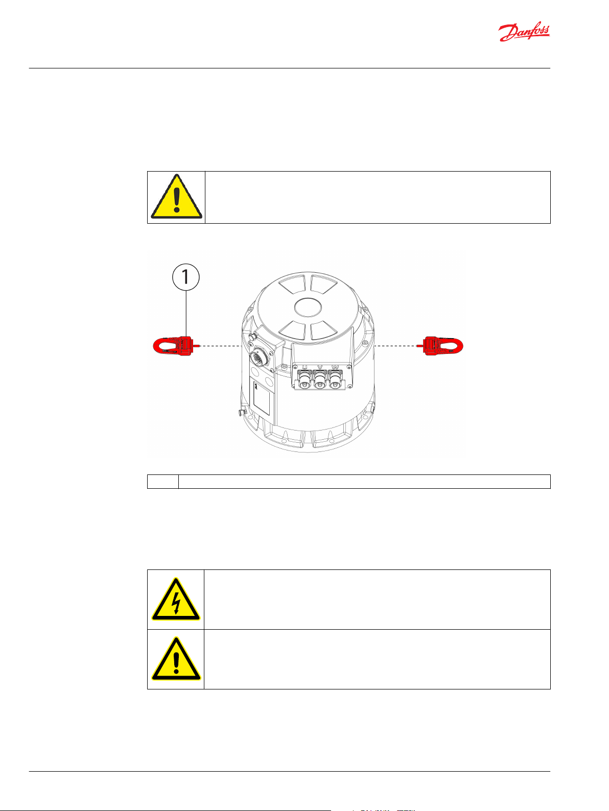
Low voltage connections
The electric machine has a connector or a connection box which is used to read out in-built temperature
and rotation sensor (resolver) data from the electric machine. The temperature data comes from PT100
sensors in the stator windings and in some cases in the bearings. The rating plate has the information
about the options of the electric machine: different options add sensors, and some electric machines do
not have all the sensors. For more information about the options, refer to Chapter Product naming
convention on page 5.
Recommended cable types for low voltage connections
Application Cable type
Resolver cabling Shielded cable (twisted pair)
Temperature measurement (PT100) Shielded cable (twisted pair)
Plug the unused socket holes of the low voltage connector with suitable plugs:
•
DEUTSCH 0413-003-1605 (size 16)
•
DEUTSCH 0413-204-2005 (size 20)
See more information and instructions about DEUTSCH connectors at https://
www.deutschconnector.com/.
Low voltage connector (1), Deutsch HD34-24-47PE
1 Low voltage connector
©
Danfoss | July 2021 BC355256345493en-000201 | 35
Page 36

User Guide
EM-PMI240-T180 User Guide
Installation
Low voltage connector details
Pin configuration of the Deutsch HD34-24-47PE connector
Deutsch HD34-24-47PE connector has two kinds of mating pins: 1 mm and 1.5 mm in
diameter.
Pin configuration of the Deutch HD34-24-47PE connector
Measurement Description PIN
Temperature 1 Temperature 1, PT100 (P), windings 47
Temperature 1, PT100 (N), windings 46
Temperature 2 Temperature 2, PT100 (P), windings 33
Temperature 2, PT100 (N), windings 32
Temperature 3 Temperature 3, PT100 (P), windings 45
Temperature 3, PT100 (N), windings 31
Temperature 4 Temperature 4, PT100 (P), windings, option TEMP4 30
Temperature 4, PT100 (N), windings, option TEMP4 29
Temperature 5 Temperature 5, PT100 (P), windings, option TEMP4 44
Temperature 5, PT100 (N), windings, option TEMP4 43
Temperature 6 Temperature 6, PT100 (P), windings, option TEMP4 28
Temperature 6, PT100 (N), windings, option TEMP4 16
Resolver COS_N Resolver, RES_COS_N, in-built non contacting 35
Resolver COS_P Resolver, RES_COS_P, in-built non contacting 20
Resolver SIN_N Resolver, RES_SIN_N , in-built non contacting 36
Resolver SIN_P Resolver, RES_SIN_P , in-built non contacting 21
Resolver EXCN Resolver, EXCN, in-built non contacting 22
Resolver EXCP Resolver, EXCP, in-built non contacting 10
Resolver shield Resolver, SHIELD/GROUND, in-built non contacting 34
36 | © Danfoss | July 2021 BC355256345493en-000201
Page 37

User Guide
EM-PMI240-T180 User Guide
Installation
Grounding connections
Ground the electric machine from its frame to make sure it functions correctly and safely.
Ground the cable shields of the power cables to make sure the electric machine functions
correctly and safely.
Ground the cable shields of the low voltage cables to make sure the electric machine
functions correctly and safely.
It is recommended to perform a ground bond test after installing the electric machine to make
sure the electric machine is correctly grounded.
The grounding points on the frame of the electric machine are for safety grounding, and
signal cables and power cable shields have their own grounding points.
©
Danfoss | July 2021 BC355256345493en-000201 | 37
Page 38

User Guide
EM-PMI240-T180 User Guide
Installation
The machine enclosure grounding point, safety grounding
1 Grounding point
Low voltage cable grounding points
Testing the power cable shield grounding (earthing)
1.
Connect one terminal of the measurement device to the cable shield of one power cable (in the
inverter end of the cable)
2.
Connect the other terminal of the measurement device to the cable shield of an other power cable.
You can also use the machine enclosure grounding point for the measurement.
3.
Measure the resistance between the two cable shields or between the cable shield and the enclosure
grounding point.
4.
Change the measurement device terminal(s) to the shield of different power cable and repeat the
measurement until all cables have been measured.
Testing the low voltage (measurement signal) cable shield grounding (earthing)
1.
Connect one terminal of the measurement device to the low voltage cable shield (in the nonmachine end of the cable).
2.
Connect the other terminal of the measurement device to the machine enclosure grounding point.
3.
Measure the resistance between the cable shield and the enclosure grounding point.
38 | © Danfoss | July 2021 BC355256345493en-000201
Page 39
User Guide
EM-PMI240-T180 User Guide
Operation
Only trained and qualified personnel familiar with the relevant safety requirements are
allowed to operate the electric machine.
Do not use the electric machine without properly dimensioned and operating cooling system.
Maximum operation temperature, current and rotational speed of the electric machine must
not be exceeded to avoid permanent damage.
The surface of the electric machine might be hot. Do not touch the electric machine during
operation.
Entanglement hazard! Do not touch the electric machine during operation.
Use the anti-condensation heater, if fitted, when the electric machine is not in use. This
prevents condensation and possible damage to the electric machine.
Use sufficient personal protective equipment when you are near the electric machine.
Read the instructions in this user guide before you install the electric machine.
©
Danfoss | July 2021 BC355256345493en-000201 | 39
Page 40
User Guide
EM-PMI240-T180 User Guide
Operation
Operation conditions
The electric machine should be used for its intended purpose only and within limits specified by the
manufacturer, concerning:
•
•
•
•
•
The electric machine is designed for the following conditions:
•
•
•
•
If electric machine operation limits are exceeded, please contact Danfoss representative.
Loading.
Cooling.
Speed range.
Service interval.
Ambient condition such as temperature and moisture.
Ambient temperature limits: -40°C...+65°C.
Maximum altitude 1000 m above sea level.
Maximum coolant liquid temperature at the inlet of the coolant circuit, see product data sheet.
Coolant liquid must be water- glycol mixture with maximum of 50 % glycol content. See
Chapter Recommended coolants.
Condition monitoring during operation
Recommended lubricants
Supervise the electric machine during operation to make sure that the electric machine
operates correctly and has a designed lifetime.
If you notice any deviations from the normal operation, for example elevated temperatures,
noise or vibration, stop the electric machine. Find the reason for the deviation and repair the
electric machine. Refer to Chapter Troubleshooting on page 49.
The maximum allowed winding temperature of the electric machine is shown on the rating
plate and in the data sheet.
Do not mix different types of greases!
Greased for life bearings do not need relubrication during their lifetime. Grease relubricable bearings
(BHS option) need regular greasing. For further information, see Chapter Bearings and lubrication on page
45.
The recommended grease type for the machine bearings is SKF LGHP-2 or equivalent. LGHP-2 is high
performance, high temperature bearing grease. For further information, see http://www.skf.com/.
40 | © Danfoss | July 2021 BC355256345493en-000201
Page 41
User Guide
EM-PMI240-T180 User Guide
Operation
Recommended coolants
Ethylene glycol is a toxic compound. Avoid exposure to the coolant.
Copper ions concentration of more than approx. 0.06 ppm causes copper induced pitting
corrosion. Do not use copper components in the cooling system.
Hard piping made of metal is recommended for the coolant instead of soft piping as rubber
hoses.
Use correct personal protective equipment when you handle the coolant.
Emergency operation
The electric machines are designed to work properly with water based coolant. Plain water with
appropriate corrosive inhibitor is acceptable, for example 50 % water- 50 % glycol coolant.
Glycol coolant options:
Ethylene glycol based Glysantin® G48® (includes also corrosion inhibitors).
•
Propylene glycol based coolants, like Splash® RV&Marine antifreeze.
•
The electric machine should be operated within the operation limits and in the conditions specified by
the manufacturer. However, it can be used with some limitations in the following fault/emergency
situations.
Cooling of the electric machine fails
The cooling system failure can be caused by dregs (sediment) accumulating to the cooling system tubes.
Try opening the possible blockage by changing the coolant flow direction. See also Chapter Cooling
system maintenance.
If the cooling of the electric machine fails, limited operation is still possible with no coolant flow. The
operation speed must be limited to half (1/2) of the rated speed and maximum 20 % of the nominal
torque may be used. In such case, the electric machine may be operated for maximum one hour. Repair
the cooling system as soon as possible. For further information, contact Danfoss representative.
The temperature measurement of the electric machine fails
The operation temperature of the electric machine is measured by PT100 temperature sensors in the
electric machine windings. The temperature signals can be read out from the measurement connector of
the electric machine, and connect to the temperature surveillance pin in the inverter for example. In case
of a temperature measurement sensor failure in the electric machine, an additional PT100 sensor can be
mounted close to the end of the windings at the low voltage (measurement signal) connector opening.
©
Danfoss | July 2021 BC355256345493en-000201 | 41
Page 42

User Guide
EM-PMI240-T180 User Guide
Operation
1. Remove the low voltage (measurement signal) connector from the electric machine enclosure. Be
2. Mount (glue) an additional PT100 temperature sensor close to the end of the windings at the
3. Connect the PT100 sensor to the low voltage connector (replace the failed sensor connection by the
4. Remount the low voltage connector to its place.
When reading the temperature (resistance) values from the additional sensor, add +15ºC to the
measured value. This gives more correct estimation of the inner temperature of the electric machine. In
case of the temperature measurement failure and using additional temperature sensor, replace the
electric machine as soon as possible, but no later than in two months.
Danfoss service contact information
Contact Danfoss service at https://danfosseditron.zendesk.com/hc/en-gb or send email to
editron.service@danfoss.com.
careful not to damage the cables and joints.
opening. Use resin/glue specified for correct temperatures (Temp.class in the rating plate, class F /
155 ºC).
new connection).
42 | © Danfoss | July 2021 BC355256345493en-000201
Page 43
User Guide
EM-PMI240-T180 User Guide
Maintenance
This Chapter contains necessary information for the qualified and trained personnel to carry out regular
maintenance work.
Do not disassemble the electric machine. Only procedures described in this user guide may be
done.
Only trained and qualified personnel familiar with the relevant safety requirements are
allowed to do maintenance to the electric machine.
Risk of electric shock when the connection box is open.
Voltage may be connected to the anti-condensation heater.
Use correct personal protective equipment when you are near the electric machine.
Read the instructions in the user guide before you start to work with the electric machine. To
make sure that the operation of the electric machine is safe and reliable, obey the
maintenance instructions.
Regular maintenance
Inspect the electric machine at regular intervals. Use the Storage, installation and maintenance
checklists on page 52.
©
Danfoss | July 2021 BC355256345493en-000201 | 43
Page 44
User Guide
EM-PMI240-T180 User Guide
Maintenance
Do not attempt to tighten bolts or screws that are not discussed in this user guide and that are
not needed for normal installation and maintenance procedures. The sealing of the bolts and
screws can break.
Correct supervision and maintenance of the electric machine makes sure that the electric machine has
reliable operation and designed lifetime.
Maintenance schedule
Object Check/Task Weekly Monthly Yearly
General construction Operation Noise, vibration. If clearly increased, contact Danfoss. X
Mounting Bolt tightness. Tighten to proper value if necessary. Applies to bolts and
screws that are discussed in this user guide. See Chapter Tightening
torques.
Bearings Listen to any unusual noise or vibration. If exists, contact Danfoss. X
Enclosure and
connected parts
Electrical system Cables Wearing of the cables. Replace if necessary. X
Electrical connections Check connections. Make sure that tightening torque is correct for the
Groundings (earthings) Check groundings (earthings). Make sure that the connection resistance
Cooling system Operation Functioning. Cooling system functions as specified. X
Tubing and connection
tightness
Ventilation plug Cleanliness. Clean if necessary. See chapter Cleaning. X
Coolant flow Coolant flow direction. Change direction by changing the connections or
Coolant quality Coolant as specified. Proper glycol used, and water/glycol mixture
Lubrication Relubrication (BHS
option)
Check cleanliness. Clean if necessary. See Chapter Cleaning X
cable glands. See Chapter Tightening torques.
is correct. Re-connect if necessary.
No visible leakage. If leaking, tighten connections appropriately, or
replace parts.
flow direction from the pump. See Chapter Cooling system maintenance.
correct. Refill if necessary. See Chapter Cooling system maintenance.
Relubricate depending on the use (see Chapter Bearings and lubrication),
if the option has been installed. Maximum relubrication interval is six
months.
X
X
X
X
X
X
X
Cleaning
Never open or remove the watertight ventilation plugs. Clean them only from the outside.
Risk of electric shock if the electric machine is cleaned against instructions allowing water to
go in to the electric machine.
Keep the electric machine clean. For cleaning, use non-abrasive and non-corrosive cleaning products.
Make sure that the detergent may be used for aluminum.
When pressure washing the electric machine, make sure that the water spray does not directly hit the
gaskets.
44 | © Danfoss | July 2021 BC355256345493en-000201
Page 45

User Guide
EM-PMI240-T180 User Guide
Maintenance
Ventilation plugs
1 Ventilation plug
Bearings and lubrication
Grease relubricable bearings
The grease relubricable bearings need regular greasing. Follow the relubrication interval and
instructions described in this Chapter.
Grease can cause skin irritation and eye inflammation. Follow all safety precautions specified
by the manufacturer of the grease.
Make sure that the automatic greasing and the oil lubrication function correctly after you
start the electric machine.
The bearing type of the electric machine can be found on the rating plate of the electric
machine.
It is recommended to have a piping for the grease exiting the electric machine. The grease
exit hole is often in an inconvenient location when the electric machine is installed.
The bearing type for electric machine is 6009/C3. See the recommended lubricant in Chapter
Recommended lubricants on page 40.
©
Danfoss | July 2021 BC355256345493en-000201 | 45
Page 46
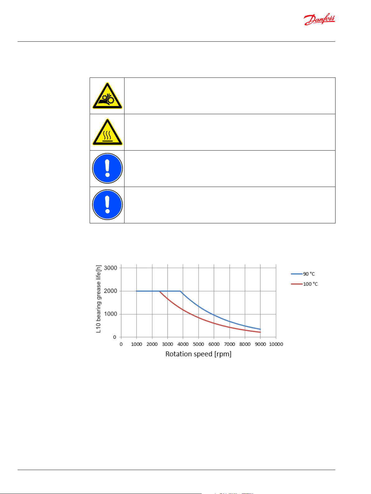
User Guide
EM-PMI240-T180 User Guide
Maintenance
Bearing relubrication
Beware of rotating parts. Do not touch the electric machine during operation.
The surface of the electric machine can be hot. Use correct protective equipment (heat
resistant gloves) when you handle the electric machine.
The information of bearing lifetime and bearing grease lifetime are estimations only to
provide a magnitude of them. The bearing lifetime and bearing grease lifetime in customer
application may vary. Danfoss is not responsible for the actual bearing lifetime in use. For
further information, contact Danfoss representative.
The maximum relubrication interval in operation is six months. The amount of grease per
relubrication is 6 g.
The relubrication interval depends on the used rotation speed and bearing temperature, and is
presented in the Figure below. The different curves represent different bearing temperatures. The higher
the temperature is and the higher the rotation speed is, the lower the relubrication interval is.
Relubrication interval of the machine (BHS option) compared to rotation speed and bearing temperature
46 | © Danfoss | July 2021 BC355256345493en-000201
Page 47
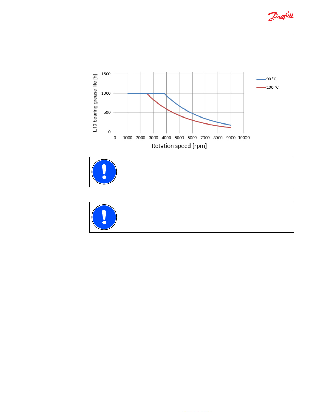
User Guide
EM-PMI240-T180 User Guide
Maintenance
Relubrication interval of the machine (BHS option) compared to rotation speed and bearing temperature,
vertical installation
For more information about the location of grease nipples and grease escape holes, see
Chapter Connections and interfaces on page 14.
Cooling system maintenance
Bearing relubrication:
It is normal if no grease exits the electric machine. This is because the cavities inside the
electric machine can hold a lot of grease.
Make sure that the electric machine has reached its operating temperature.
1.
Remove the plugs from the grease escape holes.
2.
Open the grease nipple plugs.
3.
Use grease piston to enter specific amount of grease into the grease nipple.
4.
If possible, let the electric machine run approximately one hour to let the old grease exit.
5.
Install the plugs on the grease nipples and on the grease escape holes.
6.
The electric machine cooling system requires certain regular maintenance activities.
It is recommended to change the direction of the coolant liquid flow yearly. This is done by changing the
order of the coolant connections, or changing the coolant pump direction. The reason for changing the
coolant flow direction is to prevent possible dregs (sediment) accumulating to the cooling system.
The quality of the coolant must be checked yearly. The mixture of water and glycol as well as the type of
the glycol used must be as specified. See Chapter Recommended coolants.
©
Danfoss | July 2021 BC355256345493en-000201 | 47
Page 48

User Guide
EM-PMI240-T180 User Guide
Dismounting
For dismounting the electric machine, follow the Steps below.
1. Prepare the electric machine for lifting, for more information refer to Chapter Lifting on page 24.
2. Loosen the mounting bolts. For more information refer to Chapter Mounting the electric machine on
3. If force is required, use the bores in D-end flange to push the electric machine out from the mating
4. Lift the electric machine off. Support the electric machine when lifting.
Make sure that the mating structure is not damaged. Do not pluck any bores or use at headed
bolts or rods for pushing the electric machine out of the mating structure.
Support the electric machine with lifting slings when dismounting.
page 31.
structure, or use some other method that does not damage the electric machine.
48 | © Danfoss | July 2021 BC355256345493en-000201
Page 49

User Guide
EM-PMI240-T180 User Guide
Troubleshooting
Some difficulties may occur while operating the electric machine. Possible causes and actions are given in
the Table below. If the situation occurs, it should be corrected as soon as possible. These instructions do
not cover all details or variations in the equipment nor provide information for every possible condition
to be met in connection with installation, operation or maintenance.
For more information, contact Danfoss service at https://danfosseditron.zendesk.com/hc/en-gb or send
email to editron.service@danfoss.com.
Troubleshooting chart
Symptom Possible cause Action
Excessive vibration, noise Imbalance at connected electric machine
or the powertrain components.
Attachment bolts are loose. Replace and tighten the bolts.
Imbalance at the electric machine. Contact Danfoss.
Particles inside the electric machine. Contact Danfoss.
Electric machine overheating Overload. Reduce load. Check the electric machine model description and rating
Cooling system failure. Check the cooling system integrity, flow and fluid temperature.
Leakage in the cooling system. Check the cooling system circuit and connections.
Rigid particles inside the electric
machine cooling channel.
Wrong electric machine parameters in
the inverter.
Winding short circuit. Replace the electric machine.
Electric machine does not work
properly or the performance is poor
Temperature measurement failure The PT100 sensor is faulty. Measure the resistance of the PT100 sensor, see Chapter Low
Wrong electric machine parameters in
the inverter.
Demagnetization of magnets due to
overheating.
Insulation fault. Measure the insulation resistance, refer to manufacturer limits. See
Check the balance and installation of the actuator and drivetrain
components.
plate, check the inverter limits.
Change the cooling flow direction to flush the cooling system from
sediment possibly accumulated. See also Chapter Emergency
operation.
Try pulsating coolant to open the channels. Contact Danfoss.
Check and correct the machine parameters from the inverter.
Check and correct the parameters from the inverter.
Measure the winding resistance, refer to manufacturer data. Replace
the electric machine if necessary.
Chapter Insulation resistance test. Replace the electric machine if
necessary.
voltage connections. If the sensor is faulty, read out the signal from an
other sensor. Contact Danfoss. See also Chapter Emergency operation.
©
Danfoss | July 2021 BC355256345493en-000201 | 49
Page 50

User Guide
EM-PMI240-T180 User Guide
Aftersales
Service policy
Maintenance and service of the electric machine is limited to the procedures described in this user guide.
If the electric machine has service parts available, you can find them in Chapter Service parts.
For further information, go to https://danfosseditron.zendesk.com/hc/en-gb or send email to
editron.service@danfoss.com.
50 | © Danfoss | July 2021 BC355256345493en-000201
Page 51

User Guide
EM-PMI240-T180 User Guide
Disposal
Dispose of the electric machine and any of its parts by appropriate means in accordance with local laws
and regulations.
©
Danfoss | July 2021 BC355256345493en-000201 | 51
Page 52

User Guide
EM-PMI240-T180 User Guide
Storage, installation and maintenance checklists
Electric machine installation checklist
Date:
Electric machine and customer information
Customer: Electric machine type (from the rating plate):
Customer reference: Electric machine serial number:
Service reference: Date installed:
N.A = Procedure not applicable PASS = Procedure passed FAIL = Procedure failed
Installation checklist
Approval N.A PASS FAIL
General
Electric machine type is correct ☐ ☐ ☐
Electric machine is
undamaged
Insulation resistance check >150MΩ ☐ ☐ ☐
Environmental conditions as
specified (see data sheet)
☐ ☐ ☐
☐ ☐ ☐
Mechanical installation
Supporting structure as required ☐ ☐ ☐
Shaft alignment as specified (see chapter Shaft alignment
and load).
Cooling circuit connected and coolant flowing ☐ ☐ ☐
Used coolant:
Power connections
Cable connector assembly as specified with correct cable
diameter
The phase connections order is correct (U, V, W -> L1, L2,
L3)
Grounding
Electric machine enclosure grounding connected ☐ ☐ ☐
Low voltage cable shield grounding connected ☐ ☐ ☐
Power cable shield connection resistances to ground
(electric machine enclosure) measured and valid
☐ ☐ ☐
☐ ☐ ☐
☐ ☐ ☐
☐ ☐ ☐
52 | © Danfoss | July 2021 BC355256345493en-000201
Page 53

User Guide
EM-PMI240-T180 User Guide
Storage, installation and maintenance checklists
Installation checklist (continued)
Approval N.A PASS FAIL
Low voltage cable shield grounding resistances measured
and valid
Notes:
•
•
•
•
•
•
•
•
•
•
•
•
•
Date:
Signature:
☐ ☐ ☐
Do not try to tighten bolts or screws that are not discussed in the product manual and that are not
needed for the normal installation procedures. Sealing of the screws may break.
Electric machine weekly maintenance checklist
Date:
Electric machine and customer information
Customer: Electric machine type (from the rating plate):
Customer reference: Electric machine serial number:
Service reference: Date installed:
N.A = Procedure not applicable PASS = Procedure passed FAIL = Procedure failed
Electric machine weekly maintenance checklist
N.A PASS FAIL
General construction
Noise or vibration during operation
in general
Cooling system
☐ ☐ ☐
©
Danfoss | July 2021 BC355256345493en-000201 | 53
Page 54

User Guide
EM-PMI240-T180 User Guide
Storage, installation and maintenance checklists
Electric machine weekly maintenance checklist (continued)
N.A PASS FAIL
Functioning of the cooling system in
general
Notes:
☐ ☐ ☐
•
•
•
•
•
•
•
•
•
•
•
•
Electric machine monthly maintenance checklist
Date:
Electric machine and customer information
Customer: Electric machine type (from the rating plate):
Customer reference: Electric machine serial number:
Service reference: Date installed:
N.A = Procedure not applicable PASS = Procedure passed FAIL = Procedure failed
Electric machine monthly maintenance checklist
N.A PASS FAIL
General construction
Noise or vibration during operation
in general
Cleanliness of the enclosure and
connected parts
Electrical system
Weariness of the cables ☐ ☐ ☐
Cooling system
Functioning of the cooling system in
general
Tightness of the ventilation plug ☐ ☐ ☐
☐ ☐ ☐
☐ ☐ ☐
☐ ☐ ☐
54 | © Danfoss | July 2021 BC355256345493en-000201
Page 55
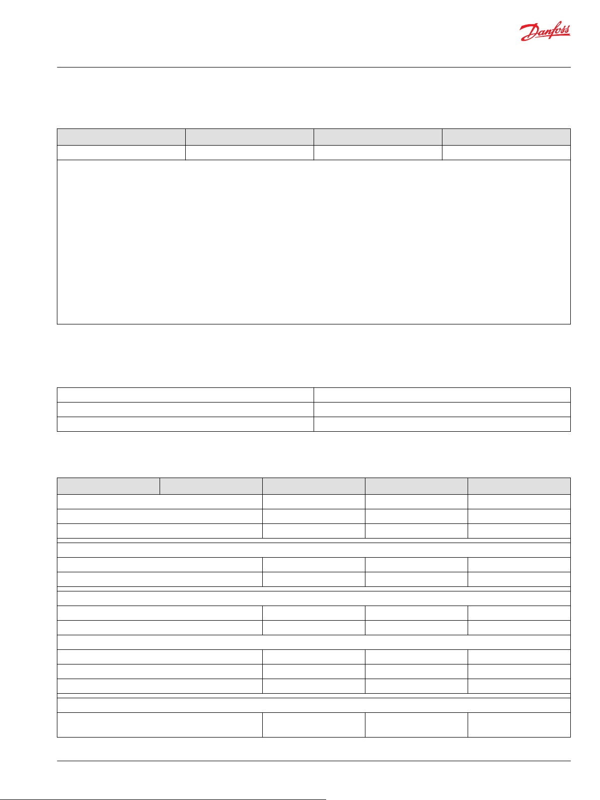
User Guide
EM-PMI240-T180 User Guide
Storage, installation and maintenance checklists
Electric machine monthly maintenance checklist (continued)
N.A PASS FAIL
Cleanliness of the ventilation plug ☐ ☐ ☐
Notes:
•
•
•
•
•
•
•
•
•
•
•
•
•
•
Electric machine yearly maintenance checklist
Date:
Electric machine and customer information
Customer: Electric machine type (from the rating plate):
Customer reference: Electric machine serial number:
Service reference: Date installed:
N.A = Procedure not applicable PASS = Procedure passed FAIL = Procedure failed
Electric machine yearly maintenance checklist
Acceptance N.A PASS FAIL
General construction
Noise or vibration during operation in general ☐ ☐ ☐
Cleanliness of the enclosure and connected parts ☐ ☐ ☐
Electrical system
Weariness of the cables ☐ ☐ ☐
Electrical connections in general ☐ ☐ ☐
Cooling system
Coolant flow direction changed and connection checked ☐ ☐ ☐
Coolant quality as specified ☐ ☐ ☐
Used coolant:
Functioning of the cooling system in general ☐ ☐ ☐
Tightness of the tubing and connections (no leakages) ☐ ☐ ☐
Cleanliness of the ventilation plug ☐ ☐ ☐
Grounding
Power cable shield connection resistances to ground
(electric machine enclosure) checked
©
Danfoss | July 2021 BC355256345493en-000201 | 55
☐ ☐ ☐
Page 56

User Guide
EM-PMI240-T180 User Guide
Storage, installation and maintenance checklists
Electric machine yearly maintenance checklist (continued)
Acceptance N.A PASS FAIL
Low voltage cable shield grounding resistances checked ☐ ☐ ☐
Notes:
•
•
•
•
•
•
•
•
•
•
•
•
•
Do not try to tighten bolts or screws that are not discussed in the product manual and that are not
needed for the normal installation procedures. Sealing of the screws may break.
For cleaning instructions, refer to Chapter Cleaning on page 44.
Used service parts
Part description Part type Quantity Item (order) number
_
_
_
_
_
Notes:
•
•
•
•
•
•
•
•
•
•
•
•
Date:
Signature:
Electric machine storage checklist
Date:
Electric machine and customer information
Customer: Electric machine type (from the rating plate):
Customer reference: Electric machine serial number:
Service reference: Date installed:
56 | © Danfoss | July 2021 BC355256345493en-000201
Page 57

User Guide
EM-PMI240-T180 User Guide
Storage, installation and maintenance checklists
This storage checklist is used when storing the electric machine. Regular inpection is required. See
specifications for storage in this User Guide or in the Data Sheet.
Fill in the date of each inspection to the Table below.
Storage checklist
Procedure Date Date Date Date Date
Storage base as
specified (vibration
free)
Storage temperature
and humidity as
specified
Electric machine type
and serial number is
correct
Electric machine
supported correctly
Shaft rotated as
specified (10 rotations
monthly)
©
Danfoss | July 2021 BC355256345493en-000201 | 57
Page 58

Danfoss
Power Solutions GmbH & Co. OHG
Krokamp 35
D-24539 Neumünster, Germany
Phone: +49 4321 871 0
Danfoss
Power Solutions ApS
Nordborgvej 81
DK-6430 Nordborg, Denmark
Phone: +45 7488 2222
Danfoss
Power Solutions (US) Company
2800 East 13th Street
Ames, IA 50010, USA
Phone: +1 515 239 6000
Danfoss
Power Solutions Trading
(Shanghai) Co., Ltd.
Building #22, No. 1000 Jin Hai Rd
Jin Qiao, Pudong New District
Shanghai, China 201206
Phone: +86 21 2080 6201
Products we offer:
Hydro-Gear
www.hydro-gear.com
Daikin-Sauer-Danfoss
www.daikin-sauer-danfoss.com
Cartridge valves
•
DCV directional control
•
valves
Electric converters
•
Electric machines
•
Electric motors
•
Gear motors
•
Gear pumps
•
Hydraulic integrated
•
circuits (HICs)
Hydrostatic motors
•
Hydrostatic pumps
•
Orbital motors
•
PLUS+1® controllers
•
PLUS+1® displays
•
PLUS+1® joysticks and
•
pedals
PLUS+1® operator
•
interfaces
PLUS+1® sensors
•
PLUS+1® software
•
PLUS+1® software services,
•
support and training
Position controls and
•
sensors
PVG proportional valves
•
Steering components and
•
systems
Telematics
•
Danfoss Power Solutions is a global manufacturer and supplier of high-quality hydraulic and
electric components. We specialize in providing state-of-the-art technology and solutions
that excel in the harsh operating conditions of the mobile off-highway market as well as the
marine sector. Building on our extensive applications expertise, we work closely with you to
ensure exceptional performance for a broad range of applications. We help you and other
customers around the world speed up system development, reduce costs and bring vehicles
and vessels to market faster.
Danfoss Power Solutions – your strongest partner in mobile hydraulics and mobile
electrification.
Go to www.danfoss.com for further product information.
We offer you expert worldwide support for ensuring the best possible solutions for
outstanding performance. And with an extensive network of Global Service Partners, we also
provide you with comprehensive global service for all of our components.
Local address:
Danfoss can accept no responsibility for possible errors in catalogues, brochures and other printed material. Danfoss reserves the right to alter its products without notice. This also applies to products
already on order provided that such alterations can be made without subsequent changes being necessary in specifications already agreed.
All trademarks in this material are property of the respective companies. Danfoss and the Danfoss logotype are trademarks of Danfoss A/S. All rights reserved.
©
Danfoss | July 2021 BC355256345493en-000201
 Loading...