

Page 1

Data Sheet
EM-PME375-T150
Electric machine, permanent magnet external
FEATURES
• Synchronous Reluctance assisted Permanent
Magnet (SRPM) technology
• Extremely compact and robust structure
• Highest efficiency throughout the operation range
on the market (~96 %)
• Liquid cooled with plain water or water/glycol
mixture
• Low coolant flow required
• Allowed coolant temperature up to +65°C
• Up to IP65 enclosure class to maximize reliability
• Multiple mounting possibilities
GENERATOR SPECIFIC FEATURES
• Standard SAE flange mounting to match the diesel
engine connection
• Wide
• Can be also used as starter motor for the ICE
selection of speed ratings allowing the
generator to be selected to customer specific
applications with various voltage requirements
MOTOR SPECIFIC FEATURES
• Extended speed and torque capabilities compared
to standard PM motors from Danfoss reluctance
assisted permanent magnet motor technology
• Motor structure is designed to be able to produce
high starting torque: EM-PME motor can produce
instantly full torque to a non-rotating shaft
• Optimized speed range to meet the most common
gear ratios used in heavy mobile machinery
GENERAL
The machine is developed especially for demanding
applications. The design of these machines makes them
smaller, lighter and more efficient than conventional
products on the market.
The machine is designed to be shorter than normal motors
for applications where axial length is crucial parameter. The
machine is designed to be connected directly to the ICE
flywheel housing with part of the motor being inside the
flywheel housing further shortening the length of the motor.
TYPICAL APPLICATIONS
• Generator for diesel-electric/serial hybrid
applications
• Traction/propulsion motor
• Generator/Motor for parallel hybrid applications
1 | © Danfoss | April 2020 AI312650743939en-000103
Page 2

Data Sheet
General electrical properties
Nominal voltage (line
to line)
500 VAC
Voltage stress
IEC 60034-25, Curve A: Without
filters for motors up to 500 VAC
Nominal efficiency
96 %
Pole pair number
10
Power supply
Inverter fed.
Minimum inverter
switching frequency
8 kHz
Basic information
Machine type
Synchronous reluctance assisted
permanent magnet
Mounting direction
Can be used in any direction, see
user guide for details.
Mounting
(IEC 60034-7)
IM 3001 (Flange)
Standard Flange D-end
(SAE J617)
SAE 3, transmission housing
Standard Flange N-end
SAE 3, flywheel housing
Standard rotation
direction
Clockwise (both directions
possible)
Protection class
(IEC 60034-5)
Up to IP65
Duty type
(IEC 60034-1)
S9
Standard color
Dark grey RAL7024 powder
coating
Mechanical
Total weight
75 kg (no options)
Moment of inertia
0.63 kgm²
Rotating mass
23 kg
Dimensions
Length (frame)
66 mm
Diameter (frame)
451 mm
Total length (frame +
195.6 mm
Cooling
Cooling liquid
Plain water with appropriate
corrosive inhibitor)
Cooling liquid
corrosive inhibitor type
Ethylene glycol Glysantin
G48 recommended
Cooling method
(IEC 60034-6)
IC 71 W
Minimum cooling
liquid flow
20 l/min
Pressure loss
0.3 bar with 20 l/min
(+25°C coolant)
Cooling liquid
temperature max
+65°C (Derating required if
exceeded)
Temperature rating
Insulation class
(IEC 60034-1)
H (180°C)
Temperature rise
(IEC 60034-1)
85°C
Maximum winding
temperature
150°C
Nominal ambient
(IEC 60034-1)
65°C
Min. ambient
temperature
-40°C
Nominal altitude
(IEC 60034-1)
1000 m
Connections
Coolant connection
2 x G1/2 bores
HV cables
3 x 50 mm2 max.
Cable direction
Cable direction radial with straight
standard angle connector
HV cable connector
3x AMPHENOL
HVBI005R10AMHARD
HV cable mating
3 x AMPHENOL HVBI-7-05R10-XFC-
connector manufacturer)
HV cable
Recommended H+S Radox
screened cable
LV connector
12 pin TE HDSCS
LV connector type
TE 1-1564520-1
LV connector pin type
Gold plated
LV mating connector
type
TE 1-1703639-1
LV mating connector
pin type
TE 1241380-2 (Gold plated)
LV connector pin
configuration
See Table below
EM-PME375-T150
SPECIFICATIONS
temperature
shaft)
2 | © Danfoss | April 2020 AI312650743939en-000103
corrosive inhibitor (max. 50 %
connector and towards N-end with
connector
XXXX-FG/PC (straight plug)
3x AMPHENOL HVBI-9-05R10-XFCXXXX-FG/PC (right angle plug)
(check the exact codes form
Page 3

Data Sheet
PIN
Description
1
Resolver, RES_COSN
2
Resolver, RES_SINN
3
Resolver, EXCN
4
Temperature, PT100, windings
5
Temperature, PT100, windings
6
Temperature, PT100, windings
7
Resolver, RES_COSP
8
Resolver, RES_SINP
9
Resolver, EXCP
10
Temperature, PT100, windings GND
11
Temperature, PT100, windings GND
12
Temperature, PT100, windings GND
Coolant temperature +65°C
Coolant temperature +40°C
Coolant temperature +40 / +65°C
Cont.
[Nm]
Cont.
[kW]
Nom.
[A]
Nom.
[A]
Nom.
[rpm]
Coolant temperature +65°C
Coolant temperature +40°C
Coolant temperature +40 / +65°C
Volt/
[V/rpm]
0
0,1
0,2
0,3
0,4
0,5
0,6
0,7
0 5 10 15 20 25 30 35
Pressure loss [bar]
Volume flow [l/min]
EM-PME375-T150
Table 1 Pin configuration of LV-connector
PRESSURE LOSS VS COOLANT FLOW
Picture 1 Pressure loss vs coolant flow
MOTORS
Type
EM-PME375-T150-1500 160 25 33 191 30 40 1500 3000 600
EM-PME375-T150-1800 167 31 40 179 33 45 1800 3600 600
EM-PME375-T150-2600 147 40 50 164 45 60 2600 4000 600
Torque
Power
Current
(* Peak torque achieved with one (350A) inverter
(** Peak torque achieved with two (350A) inverter
Cont. Torque
[Nm]
Cont. Power
[kW]
Current
speed
Max. speed
[rpm]
Peak torque
GENERATORS
[Nm]
Type
EM-PME375-T150-1500 27 26 32 33 32 39 1575 263 0.99 0.319
EM-PME375-T150-1800 34 33 39 38 36 44 1890 315 0.97 0.273
EM-PME375-T150-2600 42 41 49 50 48 59 2730 455 0.99 0.182
(*** Back EMF for cold (20°C) generator
3 | © Danfoss | April 2020 AI312650743939en-000103
Apparent
power
[kVA]
Cont.
power
[kW]
Nom.
Current
[A]
Apparent
power
[kVA]
Cont. Power
[kW]
Nom.
Current
[A]
Nom.
speed
[rpm]
Nom.
Freq.
[Hz]
Power
factor
speed
ratio
Page 4
Data Sheet
EM-PME375-T150
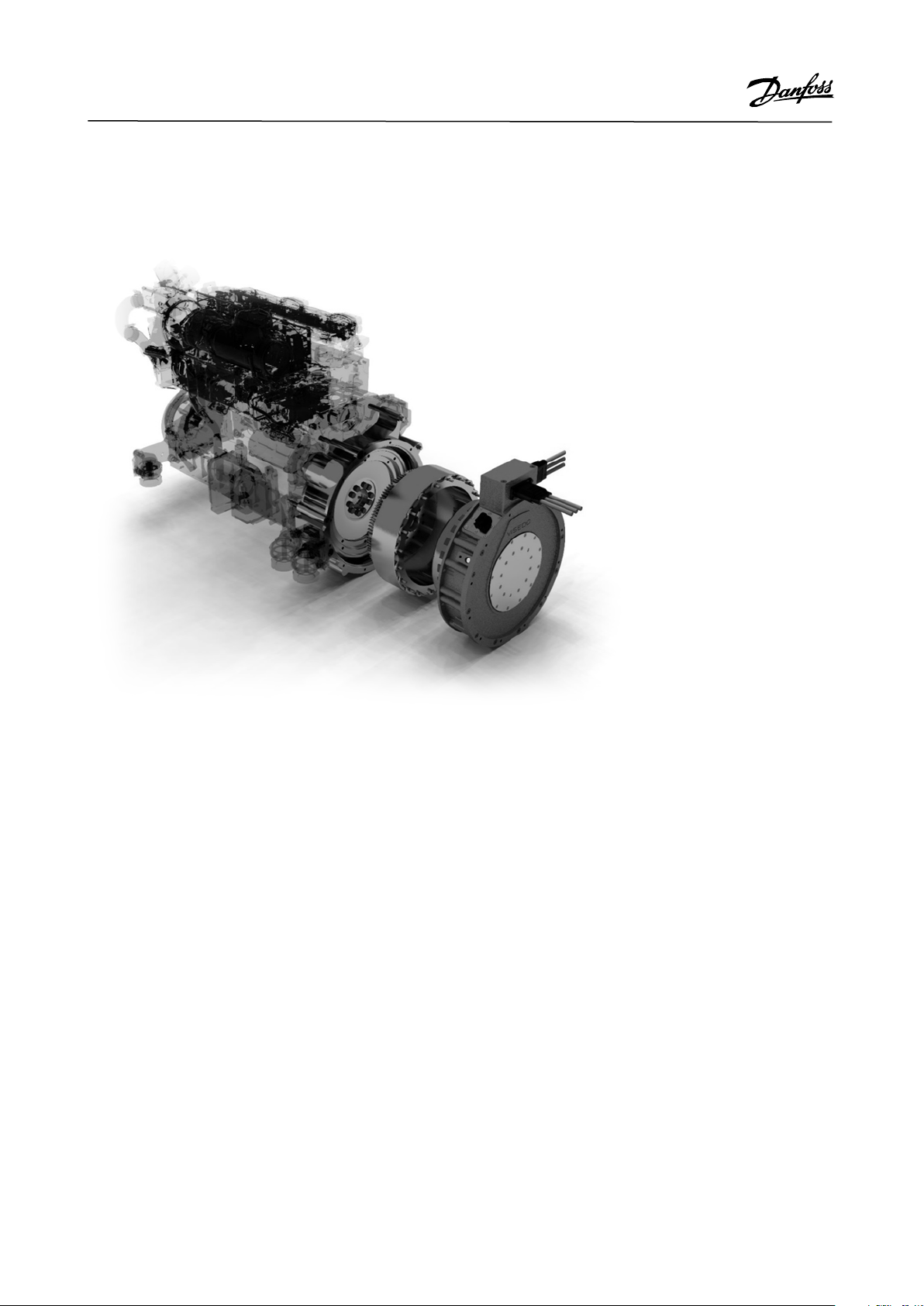
Integrated machine is commonly connected directly to the diesel engine flywheel housing. In such application, part of the motor is inside the diesel engine. Exploded view of this kind of application is shown below.
Picture 2 Integrated machine connected to diesel engine flywheel housing
4 | © Danfoss | April 2020 AI312650743939en-000103
Page 5

EM-PME375-T150-1500
EM-PME375-T150-1500+RES1
Data Sheet
EM-PME375-T150
PRODUCT CODE AND OPTIONS
Use product code including all needed options for ordering. Standard options do not need to be listed in the code as they are
selected by default if a non-standard option is not selected. Standard options are indicated by a star (*).
Product code Description
Standard unit with standard options
Standard unit otherwise but with resolver angle sensor
Table 2 Product code examples
Variant Code Description Additional information
High voltage connector * High voltage plug-in connectors
for 50 mm
+HVC1 High voltage plug-in connectors
for 35 mm
Rotation sensor * None No resolver
+RES1 Resolver In-built non contacting resolver, 5-pole pair
*Standard option
2
cables
2
cables
One plug-in connector per phase for 50 mm
cable
One plug-in connector per phase for 35 mm
cable
2
2
Table 3 Option list
Danfoss can accept no responsibility for possible errors in catalogues, brochures and other printed material. Danfoss reserves the right to alter its
products without notice. This also applies to products already on order provided that such alterations can be made without changes being necessary in
specifications already agreed. All trademarks in this material are property of the respective companies. Danfoss and the Danfoss logotype are
trademarks of Danfoss A/S. All rights reserved.
5 | © Danfoss | April 2020 AI312650743939en-000103
 Loading...