

Page 1
Data Sheet
Pressure transmitter
Type EMP 2
For monitoring and control in marine and industial applications
The high accuracy pressure transmitter EMP 2 is
designed for monitoring and control in marine
and industial applications and oers a reliable
pressure measurement, even under harsh
environmental conditions.
The exible pressure transmitter programme
covers absolute or gauge (relative) versions
with zero and span adjustment with a 4 – 20
mA output signal.
It has all the necessary marine approvals.
Special versions with integrated pulse-snubber
available, designed for use in hydraulic
applications with severe medium inuences
like cavitation, liquid hammer or pressure
peaks.
Features
• For use in Zone 2 explosive atmosphere
AI175686432328en-000901
Page 2
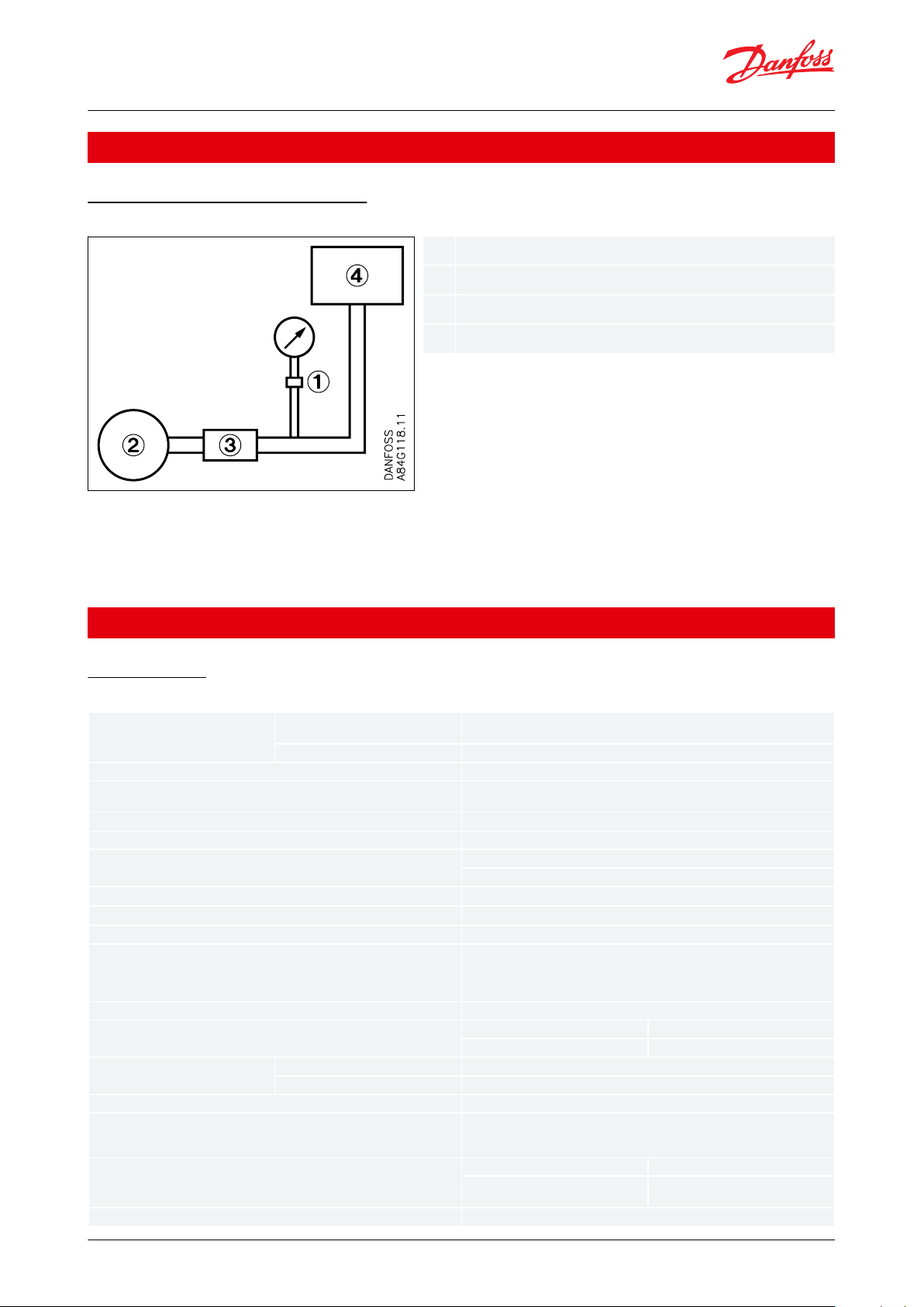
1234Surge damper
Pump
Valve
Tank
Sensor temperature range
Normal
-10 – 70 °C, (Ref.
Figure 2: Max. ambient temperature as a function of
temperature)
ATEX Zone 2
-10 – 85 °C
Transport / storage temperature
-50 – 70 °C
Media temperature
-40 – 100 °C, (Ref.
Figure 2: Max. ambient temperature as a function of
temperature)
Media
Water, fuel, oil, lubricating oil, refrigerants, ammonia, gas etc.
Voltage supply
Max. 32 V and min. 12 V DC between terminals N and P
Load resistance
A. max. 410 Ω at 24 V DC 50% / -20%
B. max. 650 Ω at 24 V DC 50% / 0%
Zero point adjustment
- 5 – 20% range span; but max. -1–1.5 bar (kp/cm
2
)
Span adjustment
± 5% of range span; max. ± 5 bar (kp/cm
2
)
Combination of span and zero point adjustments
- 5 – 20% of range span
Noise – immunity
Complies with the standard for industrial apparatus EN 61000-6-2. The standard
contains tests for the following: HF elds, mains transmitted HF, voltage transients, electrostatic immunity, supply voltage variations, low-frequency radiation
and transient protection in accordance with Germanischer Lloyd
Noise – emission
Complies with standard EN 61000-6-3
Accuracy
< 0.3 % of FS
In vacuum (below 0 bar)
< 2.3 % of FS
Temperature dependence
Thermal zero point shift
≤ ± 0.06 % FS / °C
Thermal sensitivity (span) shift
≤ ± 0.06 % FS / °C
Voltage dependence
≤ ± 0.1% FS / 10 V
Vibration stability
3 – 30 Hz amplitude 1.13 mm and 30 – 300 Hz acceleration 4G according to IEC
60068-2-6. The requirements of the ship classication societies are up to 100 Hz,
acceleration 4G. Extended specications by prior arrangement
Time constant
Liquids with viscosity < 100 cSt
< 4 ms
Air and gas in combination with pulse
snubber:
< 35 ms
Shock stability
500 g for 1 ms to IEC 60068-2-27
Pressure transmitter, Type EMP 2
Applications
Application and media conditions
Figure 1: Pressure range
In cases where valves are closed momentarily, surges of a value in excess of that for which the pressure element is
designed can occur. To avoid damage to the pressure element, a damper should be tted.
The device can consist of a exible pipe, a throttle, a shock valve, or a combination of these items. The amplitude of
surges should never exceed the maximum pressure range of the pressure transmitter.
Product specication
Technical data
Table 1: Performance (EN 60770)
© Danfoss | Climate Solutions | 2021.02 AI175686432328en-000901 | 2
Page 3

A
D
B
C
ABCDAmbient temperature
Temperature and medium
Operating range
Transport and storage temperature
Enclosure
IP65, Housings are made of enamelled pressure-die-cast aluminium (GD-AISI 12)
Pressure connection
G ¼, G ½ A standard, G ⅜ A mano
Net weight
approx. 1 kg
Cable entry
Pg 13.5 for cable diameters 5 – 14 mm
Zone 2 applications
(1)
EN60079-0; EN60079-15
Pressure transmitter, Type EMP 2
Table 2: Explosive atmospheres
(1)
(1)
When used in ATEX Zone 2 areas at temperatures <-10 °C the cable and plug must be protected against impact
When used in ATEX Zone 2 areas at temperatures <-10 °C the cable and plug must be protected against impact
Identication
The type designation and code number of the transmitter is embossed on the side of the housing at the bottom
close to the pressure connector.
Installation conditions
Figure 2: Max. ambient temperature as a function of temperature
Mounting
Type EMP 2 is equipped with a 3 mm stell bracket for mounting.
Pressure connection
Connector with outside cylindrical thread G ½, some types available with G ⅜ A mano, and inside cylindrical thread
G ¼, to ISO 228.
The primary insertion length of the connector corresponds to EN 837. Connection to the transmitter is made
through a connector with a spanner at, 14 mm across ats.
When tting or removing pressure lines, the spanner ats on the pressure connector should be used to apply
counter-torque.
© Danfoss | Climate Solutions | 2021.02 AI175686432328en-000901 | 3
Page 4

A
B
C
D
E
F
ABCDEFmax. 70 °C
Condensed liquid
Reliable, good convection
Insulation against radiant heat
Steam 170 °C
Thin (=low heat conductivity)
uninsulated tube
Pressure transmitter, Type EMP 2
Figure 3: Insulation against radiant heat
Water systems
Water in the pressure element is not harmful, but in the event of frost a water-lled pressure element may burst. To
prevent this the transmitter should be allowed to operate on an air cushion.
Steam plant
To protect the pressure element against temperatures in excess of the maximum temperature for the medium (100
°C), the insertion of a water-lled loop is recommended. In the example, Figure 3: Insulation against radiant heat,
insulation against radiant heat is also shown.
Electrical connection
Figure 4: Wiring diagram
The transmitter has a wiring diagram, see above gure. Terminals P (positive) and N (negative) are connection
terminals for the supply voltage.
The same leads are used for supply voltage and output signal. A function test can be performed between terminals
N and T without cutting o the current loop.
© Danfoss | Climate Solutions | 2021.02 AI175686432328en-000901 | 4
Page 5

ABC
G ½ A (G 3/8 A mano)
Pg 13.5
G ¼
1
1
Pulse-snubber
Pressure transmitter, Type EMP 2
Pulse snubber
Figure 5: pulse snubber
EMP 2 with the pressure range 0 – 6 bar and 0 – 10 bar at extended test pressure is provided with an integrated
pulse snubber for protection of the sensor element against cavitations and air bubbles in the media due to extreme
pressure peaks and pulsations. Such conditions may be caused by pumps or fast operation valves in both high and
low pressure systems.
The integrated pulse snubber is designed as an 0.3 mm orice mounted in the pressure connection. The medium
should not contain particles which may clog up in the orice.
The viscosity has only little eect on the response time. Even at liquid viscosities up to 100 Cst the response time will
not exceed 4 ms.
Dimensions and weight
Net weight 1 kg
Figure 6: Dimensions diagram
© Danfoss | Climate Solutions | 2021.02 AI175686432328en-000901 | 5
Page 6

Operating pressure
Test pressure
Min. burst pressure
Code no. EMP 2
pe [bar]
pe [bar]
pe [bar]
G ½ A
G ⅜ A
-1 – 1.5
(1)
5
100
084G2100
-
-1 – 5
(1)
35
200
084G2101
-
0.2 – 1
3.2
100
084G2102
-
0 – 1.6
3.2
100
084G2104
-
0 – 2.55200
084G2105
-
0 – 48200
084G2106
084G2206
0 – 618400
084G2107
084G2207
0 – 6
60
(2)
400
084G2108
-
0 – 1020400
084G2109
084G2209
0 – 10
60
(2)
400
084G2110
-
0 – 1632400
084G2111
084G2211
0 – 2550400
084G2112
-
0 – 4080400
084G2113
084G2213
0 – 60
120
400
084G2114
-
0 – 100
200
400
084G2115
-
0 – 160
260
640
084G2116
-
0 – 250
375
1000
084G2117
-
-1 – 9
(1)
20
400
084G2120
-
Operating pressure
Test pressure
Min. burst pressure
Code no. EMP 2
pe [ kp/cm2]
pe [ kp/cm2]
pe [ kp/cm2]
G ½ A
G ⅜ A
-1 – 5
(1)
35
200
084G2131
-
0 – 48200
084G2136
084G2157
0 – 618400
084G2137
084G2158
0 – 1020400
-
084G2179
0 – 1532400
084G2141
084G2159
0 – 2550400
084G2142
-
0 – 4080400
084G2143
084G2169
0 – 50
120
400
084G2144
-
0 – 2050400
084G2154
-
Pressure transmitter, Type EMP 2
Ordering
Table 3: Pressure in bar
(1)
(1)
Sealed gauge
Sealed gauge
(2)
(2)
With pulse snubber
With pulse snubber
Table 4: Pressure in kp/cm
2
NOTE:
When ordering please state type and code number
© Danfoss | Climate Solutions | 2021.02 AI175686432328en-000901 | 6
Page 7

Part
Symbol
Description
Material
Code no.
Damping coil
Damping coil with G 3/8 unions and 1.5 m copper
capillary tube.
Copper
060-104766
Damping coil
Damping coil with G ½ unions and 1 m capillary
tube. Standard washers supplied
Stainless steel
060-016966
Damping coil, arm-
oured
Damping coil with G ³⁄8 unions and 1 m armoured
copper capillary tube. Standard washers supplied
Copper
060-333366
Nipple
G ¼ A × G 3/8A with copper washer
Brass
060-333266
G ¼ A × M10 ext. × 1 with copper washer
Brass
060-333866
Pascal (=
Newton per
square me‐
tre)
Newton per
square [mm]
[bar]
Kilopond
per square
metre [mm]
H2O
Meter water
gauge
Technical at‐
mosphere
[kp/cm2]
Physical at‐
mosphere
Torr [0 °C]
Inches Hg [0
°C]
Poundforce
per Square
inch
[N/m
2
] Pa
[N/mm
2
]
[kp/m
2
]
[m] H
2
O
[at]
[atm]
[mm] Hg
[in] Hg
[lbf/in
2
] psi
1 Pa
1
10-610
-5
0.1020
1.020 • 10
-4
1.020 • 10
-5
9.869 • 10
-5
7.500 • 10
-3
2.953 • 10
-4
1.450 • 10
-4
1 N/mm
2106
1
10
1.020 •10
5
10.20
10.20
9.869
7.5 • 10
3
295.3
145.0
1 bar
10
5
0.1
1
10.197 • 10
3
10.20
1.020
0.9869
750
29.53
14.50
1 kp/m
2
9.80665
9.807 • 10
-6
9.807 • 10
-5
1
10-310-40.9678 • 10
-4
0.07355
2.896 • 10
-3
1.422 • 10
-3
1 m H
2
O
9806.7
9.807 • 10
3
0.09807
100010.1
0.09678
73.55
2.896
1.422
1 at
98.066 • 10
3
0.09807
0.9807
104101
0.9678
735.5
28.96
14.22
1 atm
101.325 • 10
3
0.1013
1.013
10.333 • 10
3
10.33
1.0331760
29.92
14.70
1 mm Hg
133.32
1.333 • 10
-4
1.333 • 10
-3
13.60
0.01360
1.360 •10
-3
1.316 • 10
-3
1
0.03937
1.934 • 10
-2
1 in Hg
3387
3.387 •10
-3
0.03387
345.3
0.3453
0.03453
0.03342
25.410.4912
1 psi
6895
6.895 • 10
-3
0.06895
703.1
0.7031
0.07031
0.06804
51.71
2.036
1
Pressure transmitter, Type EMP 2
Accessories
Table 5: Accessories list
Conversion table
Table 6: Conversion values
© Danfoss | Climate Solutions | 2021.02 AI175686432328en-000901 | 7
Page 8

File name
Document type
Document topic
Approval authority
RU Д-DK.БЛ08.B.00302_18
EAC Declaration
EMC
EAC
DLN 34014-AE003
Marine - Safety Certicate
-KRELE071320XP
Marine - Safety Certicate
-
RINA
2002547TA
Marine - Safety Certicate
-LRTJ18T00028
Marine - Safety Certicate
-
CCS
TAA000012U
Marine - Safety Certicate
-
DNV GL
18.10316.266
Marine - Safety Certicate
-
RMRS
TA19494M
Marine - Safety Certicate
-
NKK
02280-H0 BV
Marine - Safety Certicate
-BV15-LD1339318-PDA
Marine - Safety Certicate
-
ABS
DK.C.30.018.A 31316
Measuring - Performance Certicate
-
GOST
064G9615.06
EU Declaration
ATEX/EMCD/RoHS
Danfoss
UA.1O146.D.00075-19
UA Declaration
EMCD/LVD
LLC CDC EURO TYSK
CRN.0F18477.5123467890YTN
Pressure - Safety Certicate
CRN
TSSA
064R9402.00
Manufacturers Declaration
PED
Danfoss
SMS.W.II-2179-B.0
Marine - Manufacturing Permission
-BVE494625
Electrical - Safety Certicate
-
UL
Pressure transmitter, Type EMP 2
Certicates, declarations, and approvals
The list contains all certicates, declarations, and approvals for this product type. Individual code number may have
some or all of these approvals, and certain local approvals may not appear on the list.
Some approvals may change over time. You can check the most current status at danfoss.com or contact your local
Danfoss representative if you have any questions.
Table 7: Certicates and declarations
© Danfoss | Climate Solutions | 2021.02 AI175686432328en-000901 | 8
Page 9

Online support
Danfoss oers a wide range of support along with our products, including digital product information, software,
mobile apps, and expert guidance. See the possibilities below.
The Danfoss Product Store
The Danfoss Product Store is your one-stop shop for everything product related—no matter where
you are in the world or what area of the cooling industry you work in. Get quick access to essential
information like product specs, code numbers, technical documentation, certications, accessories,
and more.
Start browsing at store.danfoss.com.
Find technical documentation
Find the technical documentation you need to get your project up and running. Get direct access to
our ocial collection of data sheets, certicates and declarations, manuals and guides, 3D models
and drawings, case stories, brochures, and much more.
Start searching now at www.danfoss.com/en/service-and-support/documentation.
Danfoss Learning
Danfoss Learning is a free online learning platform. It features courses and materials specically
designed to help engineers, installers, service technicians, and wholesalers better understand the
products, applications, industry topics, and trends that will help you do your job better.
Create your Danfoss Learning account for free at www.danfoss.com/en/service-and-support/learning.
Get local information and support
Local Danfoss websites are the main sources for help and information about our company and
products. Find product availability, get the latest regional news, or connect with a nearby expert—all
in your own language.
Find your local Danfoss website here: www.danfoss.com/en/choose-region.
Spare Parts
Get access to the Danfoss spare parts and service kit catalog right from your smartphone. The app
contains a wide range of components for air conditioning and refrigeration applications, such as
valves, strainers, pressure switches, and sensors.
Download the Spare Parts app for free at www.danfoss.com/en/service-and-support/downloads.
Danfoss can accept no responsibility for possible errors in catalogues, brochures and other printed material. Danfoss reserves the right to alter its
products without notice. This also applies to products already on order provided that such alterations can be made without subsequential
changes being necessary in specications already agreed. All trademarks in this material are property of the respective companies. Danfoss and
the Danfoss logotype are trademarks of Danfoss A/S. All rights reserved.
© Danfoss | Climate Solutions | 2021.02 AI175686432328en-000901 | 9
 Loading...