

Page 1
Instructions
Electronic module on
SH/SY/SZ compressors
Introduction
Large scroll compressors are delivered with
a pre-installed electronic module located in
the terminal box. This procedure describes
electronic module’s functions, fault diagnosis
and how to replace an electronic module on
SH/SY/SZ compressors.
These operations must be performed by
qualied personnel in compliance with all
pertinent practices and safety procedures.
Functional description
The electronic module device provides
ecient and reliable protection against motor
overheating and overloading as well as phase
loss and phase reversal detection.
1.Motor overheating and overloading
The motor protector comprises a control
module and PTC sensors embedded in the
motor winding. The close contact between
thermistors and windings ensures a very low
level of thermal inertia.
The motor temperature is constantly measured
by a PTC thermistor loop connected on
S1-S2. If the thermistor exceeds its response
temperature, its resistance increases above the
trip level (4,500 Ω ) and the output relay then
trips, i.e. contacts M1-M2 are open. After cooling
to below the response temperature (resistance
< 2,750 Ω), a 5-minute time delay is activated.
After this delay has elapsed, the relay is once
again pulled in, i.e. contacts M1-M2 are closed.
The time delay may be cancelled by means
of resetting the mains (L-N-disconnect) for
approximately 5 seconds.
A red/green twin LED is visible on the
module. A solid green LED denotes a fault
free condition. A blinking red LED indicates an
identiable fault condition:
PTC overheat
PTC reset delay active (after PTC over temp.)
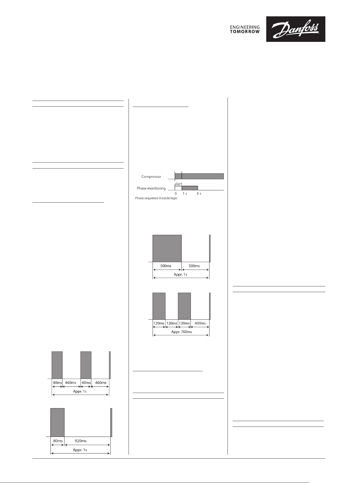
2.Phase loss, phase sequence
The electronic module provides protection
against phase reversal and phase loss at start-up.
The circuit should be thoroughly checked in
order to determine the cause of the phase
problem before re-energizing the control circuit.
The phase sequencing and phase loss
monitoring functions are active during a 5-sec
window 1 second after the compressor start-up
(power on L1-L2-L3).
Should one of these parameters be incorrect,
the relay would lock out (contact M1-M2 (or 11-
14) open). The red LED on the module will show
the following blink code:
In case of phase loss error
In case of phase reverse error
The lockout may be cancelled by resetting
the power mains (disconnect L-N) for
approximately 5 seconds.
3. Internal module failure protection:
An internal microprocessor fault leads to trip;
relay contact M1-M2 open.
Fault diagnosis
If the relay contacts M1-M2 are open, carry out
following steps:
1. Check all electrical connections (wiring,
drawing conformity, connection tightness…)
2. Try to reset by interrupting mains supply to
the module for at least 5 seconds.
3. If after reset the relay contacts M1-M2 are
now closed, a fault in motor power supply or
high motor temperature had caused a trip
condition
(missing phase, wrong phase sequence,
operating outside of the compressor operating
envelope…).
4. If the relay contact M1-M2 remains open:
4.1 Disconnect the PTC thermistor leads and
measure the resistance value at this point (max
measurement voltage 3V).
• R=∞: PTC loop opened remove the
compressor.
• R>2750Ω: wait until compressor motor
winding temperature has cooled down,
reconnect PTC and try to reset check root
causes of motor over heating (operation outside
of working envelope…).
•
150Ω<R<1250Ω: normal resistance value for PTC
at ambient temperature continue with step 4.2.
• R=0Ω: PTC loop in short circuit replace the
compressor.
4.2 Following steps describe how to test the
module itself within the terminal box:
• Disconnect L-N.
• Disconnect S1-S2.
•Disconnect M1-M2.
• Reconnect mains supply L-N.
• Bridge S1-S2.
• Try to reset by interrupting mains supply to the
module for at least 5 seconds.
•
Check relay contacts M1-M2 with an ohmmeter.
• If the relay contacts M1-M2 are closed, module
is OK.
• If the relay contacts M1-M2 are still open
replace the module.
Replacement/Installation
1. Lock-out power supplies if compressor is
installed.
2. Remove electrical box cover.
3. Before removing wires, label the wires so they
can be connected to the correct connections
on the replacement module. Unplug wires
connected to the module.
4. Remove the two 3.5x25mm screws holding
the module and replace with required module.
5. If the change is to have a dierent module
supply voltage, please indicate the new electronic
module supply voltage close to the compressor
nameplate in case of compressor replacement.
6. Use two 3.5x25mm screws (torque: 0.5 to
2N.m), to mount the new module in place of the
existing one.
7. Connect thermistor wires and 3 phase wires
(when present) to the module. In case of the
installed compressor, connect safety circuit and
power supply wires to the module.
8. Snap the electrical box cover in place.
9. Reconnect power to compressor and module.
Handling and storage
• Handle the electronic module with care.
• In case of shock, the electronic module
should not be used.
• Store between -35°C and + 70°C.
• Don’t expose to rain or corrosive atmosphere.
© Copyright Danfoss | Commercial Compressors | 2015.03FRCC.PI.031.A2.02 - March 2015 - 8510268P01B
Page 2
Blue
Compressor Model
SM/SY/SZ175 to 380
& SH180 - 240 to 485
SM/SY/SZ175 to 380
& SH180 - 240 to 485
Electronic Module Description
Electronic Module 24V AC
Electronic Module
115/240V AC
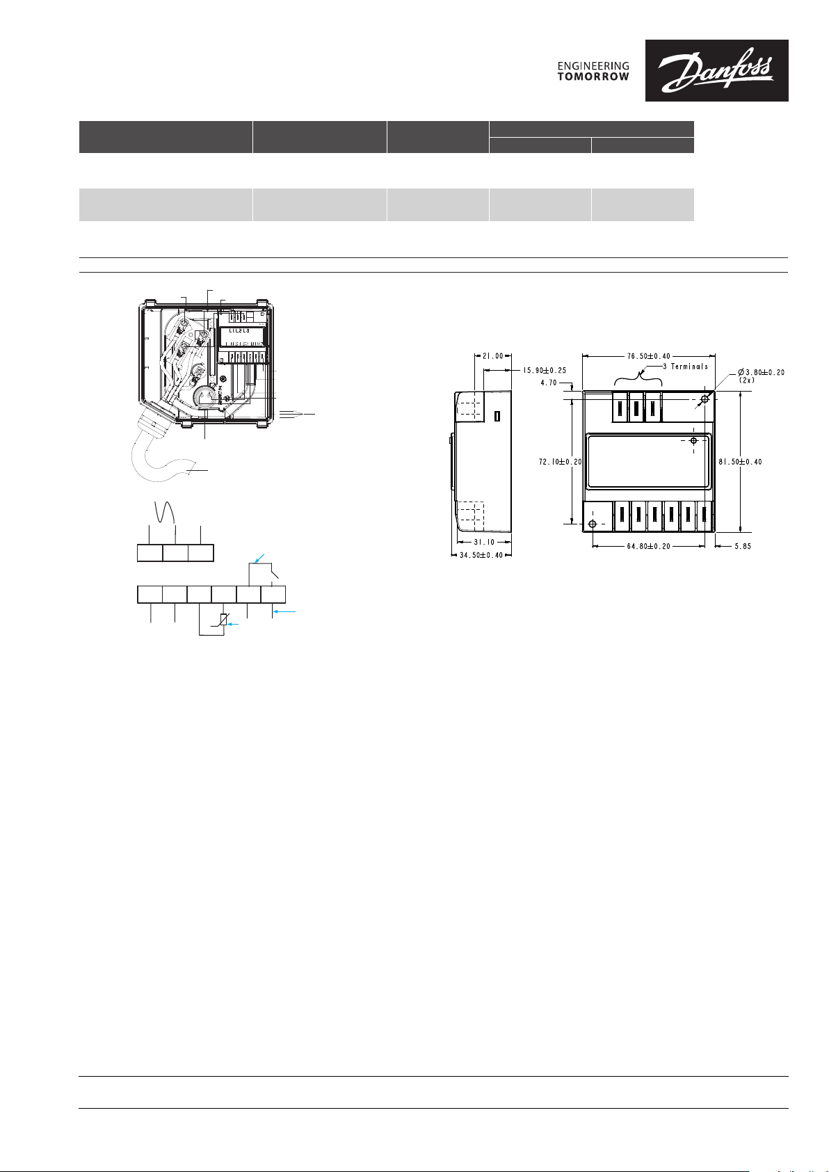
Electronic module overview
Danfoss Accessory
code
120Z0584
120Z0585
Codes marked on module nameplate
Module name Danfoss part number
DEP101A 6914009P01
DEP101B 6914010P01
Black
Phase sequence input
L1 L2 L3
Black Blue Brown
Brown
Faston 1/4” tabs
Power supply
Internal control contact
LNS1 S2 M1 M2
Thermistor
Module power
connection
M1 - M2
Control circuit
Module
}
power supply
}
Sump heater
Safety
circuit
Danfoss can accept no responsibility for possible errors in catalogues, brochures and other printed material. Danfoss reserves the right to alter its products without notice. This also applies to products
already on order provided that such alterations can be made without subsequential changes being necessary in specications already agreed.
All trademarks in this material are property of the respective companies. Danfoss and the Danfoss logotype are trademarks of Danfoss A/S. All rights reserved.
© Copyright Danfoss | Commercial Compressors | 2015.03FRCC.PI.031.A2.02 - March 2015 - 8510268P01B
 Loading...