

Page 1
Data Sheet
Electronic Foot Pedal
Over Center Rocker Type/Bi-directional
The rocker type Electronic Foot Pedal is used to drive
off-highway vehicles equipped with hydrostatic
transmissions and/or electronically controlled
engines. The foot pedal typically provides speed
commands to the electronic transmission or the
engine controller, where the output signal of the foot
pedal is proportional to the angle of the foot pedal
actuation. The rocker type foot pedal is commonly
used on vehicle applications that have a high duty
cycle of direction changes (forward/neutral/reverse).
For example: warehouse trucks, piggy-back fork
trucks, and other material handling equipment.
The electronic foot pedal features a specially
designed sensor for heavy equipment applications
which uses Hall effect technology. This special sensor
offers two different types of redundant signals to fit a
variety of control strategies. In addition, the
redundant sensors have independent isolated circuits
and protection against electrical misconnection.
Features
•
Robust over-center rocker pedal
•
14 +/- 2 degrees angular rotation fore
and aft
•
3 million full actuation cycle life
•
Non-contact ratiometric Hall effect
sensors
•
Independent isolated redundant
sensors
•
Protected against electrical
misconnection
•
IP 66 sealed electronics
•
Wide operating temperature
•
Withstands high static loads
Comprehensive technical literature online
at powersolutions.danfoss.com
©
Danfoss | Aug 2016 L1024042 | AI00000110en-US0302 | 1
Page 2
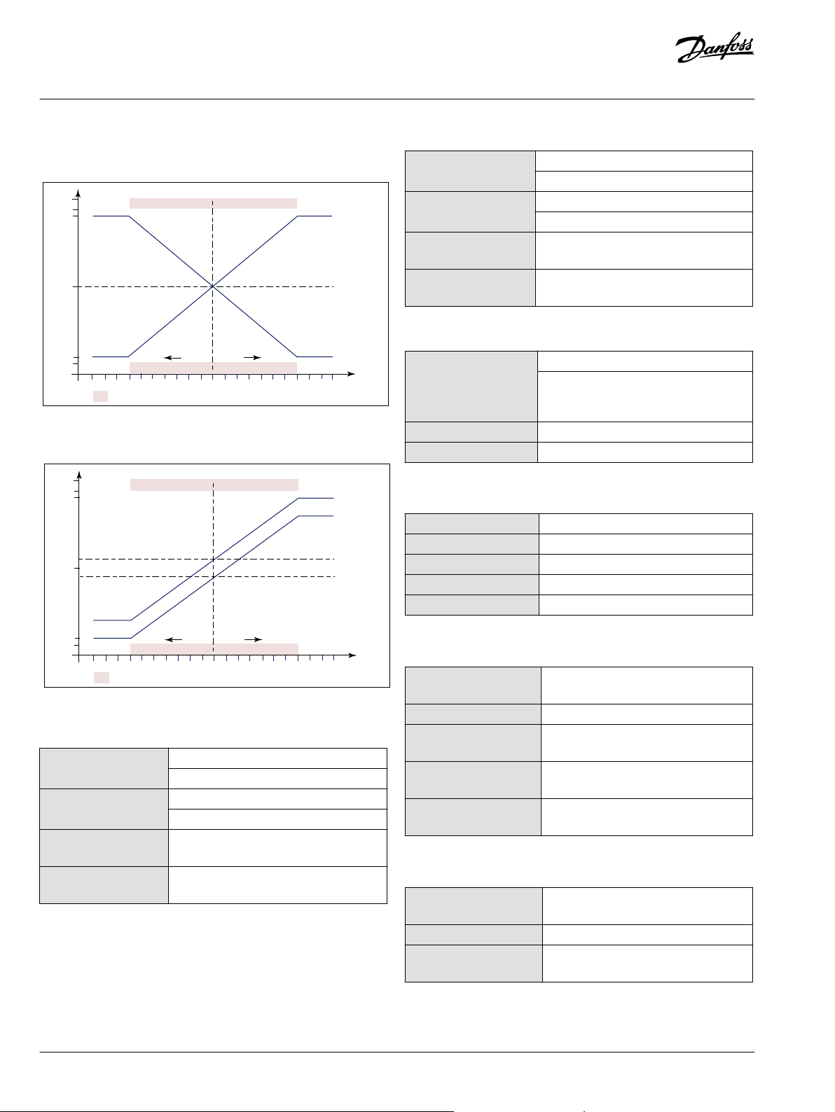
100%
Dir. A
Dir. B
50%
Sensor 2 output
(percent of
input voltage)
Sensor 1 output
(percent of
input voltage)
94%
90%
10%
5%
Neutral position
Pedal angle
-20°
-18°
-16°
-14°
-12°
-10°
-8°
-6°
-4°
-2°
-0°
2°
4°
6°
8°
10°
12°
14°
16° 18°
20°
Fault area
100%
50%
Sensor 2 output
(percent of input voltage)
Sensor 1 output
(percent of input voltage)
94%
90%
10%
5%
Neutral position
Pedal angle
-20°
-18°
-16°
-14°
-12°
-10°
-8°
-6°
-4°
-2°
-0°
2°
4°
6°
8°
10°
12°
14°
16° 18°
20°
Fault area
Neutral position
Dir. A
Dir. B
Data Sheet
Electronic Foot Pedal Bi-directional
Technical Data
Option 1: 10%-90% and 90%-10%
Option 2: 20%-90% and 10%-80%
Option 2: Signal Level
Signal 1 range nominal
(APS1)
Signal 2 range nominal
(APS2)
Neutral 1 range nominal
(APS1)
Neutral 2 range nominal
(APS2)
Minimum (Uout/Ucc): 20%, +4% and -2%
Maximum (Uout/Ucc): 90%, +2% and -4%
Minimum (Uout/Ucc): 10%, +4% and -2%
Maximum (Uout/Ucc): 80%, +2% and -4%
(Uout/Ucc): 45% ± 4%
(Uout/Ucc): 55% ± 4%
Specifications
Supply voltage (Ucc1,
Ucc2) Current
consumption (each Hall
element)
Operating temperature -40 to +85° C [-40 to +185° F]
Sealing of electronics IP 66
5 Vdc ± 0.5 Vdc
Maximum: 10 mA (for both Hall elements 20
mA)
Material
Casting Irridited aluminum
Hall element shaft Stainless steel
Base plate Zinc plated steel
Spring Stainless steel
Weight Typical: 2.6 Kg [5.6 lbs]
Mechanical Ratings
Pedal angle (toeboard
angle)
Activations (full stroke) Minimum: 3 million
Option 1: Signal Level
Signal 1 range nominal
(APS1)
Signal 2 range nominal
(APS2)
Neutral 1 range
Minimum (Uout/Ucc): 10%, +4% and -2%
Maximum (Uout/Ucc): 90%, +2% and -4%
Minimum (Uout/Ucc): 90%, +2% and -4%
Maximum (Uout/Ucc): 10%, +4% and -2%
50% ± 4%
Static load limit (forward
or reverse)
Side load limit Maximum: 500 N (measured 150mm from
Vertical load limit
(neutral)
nominal (APS1)
Neutral 2 range
nominal (APS2)
2 | © Danfoss | Aug 2016 L1024042 | AI00000110en-US0302
50% ± 4%
Signal Output
Signal current (APS1,
APS2)
Signal load Maximum: 10 K Ohms
Short circuit of signal
(APS1, APS2)
Maximum: 14° ± 2°
Maximum: 1500 N (measured 150mm from
pivot)
pivot)
Maximum: 1000 N (measured center of
treadle on pivot axis)
Maximum: 0.5 mA
Maximum: 20 minutes
Page 3

A
B
C D E F
Data Sheet
Electronic Foot Pedal Bi-directional
Sensor Connections
Pin Function Color
A Signal 1 = Us1 Black
B Ground 1 = GND1 White
C Supply 1 = Ucc1 Red
D Supply 2 = Ucc2 Green
E Ground 2 = GND2 Blue
F Signal 2 = Us2 Orange
Ordering Information
Part number Description
11065877 Option 1 Bi-directional
11065874 Option 2 Bi-directional
11065878 100 cm Cable
©
Danfoss | Aug 2016 L1024042 | AI00000110en-US0302 | 3
Page 4

Danfoss can accept no responsibility for possible errors in catalogues, brochures and other printed material. Danfoss reserves the right to alter its products without notice. This also applies to products
already on order provided that such alterations can be made without changes being necessary in specifications already agreed.
All trademarks in this material are property of the respective companies. Danfoss and the Danfoss logotype are trademarks of Danfoss A/S. All rights reserved.
4 | © Danfoss | Aug 2016 L1024042 | AI00000110en-US0302
 Loading...