

Page 1
Electronically controlled PTC Starting Device
Approx. 6 s
Minimum 120
s
ON
OFF
27.9
48.5
37
8556
ePTC - Product Description
Technical Info
Introduction
The asynchronous motor of a single
phase AC powered compressor
has two windings, a main and an
auxiliary winding. The auxiliary
winding is powered high at start
by means of a starting device, then
powered down, often still utilized
continuously by means of a run
capacitor. The starting device of our
standard PTC-starters is a “Positive
Temperature Coefficient” resistor,
PTC. When heated up during the
start phase, the PTC almost cuts
off the current to the auxiliary winding, leaving only enough current
to keep itself heated to this closing
level. The heat loss for this amount
to approximately 2.5 W. With the
ePTC this loss can be reduced
to approximately 0.4 W by an extra
electronic circuit.
down
Features
The electronic design of the staring
device offers some strong features
such as:
• Restart of compressor possible
after a few seconds. Only very
short cooling time necessary,
due to the electronic design.
• Operational wattage loss
reduced by 2 Watt.
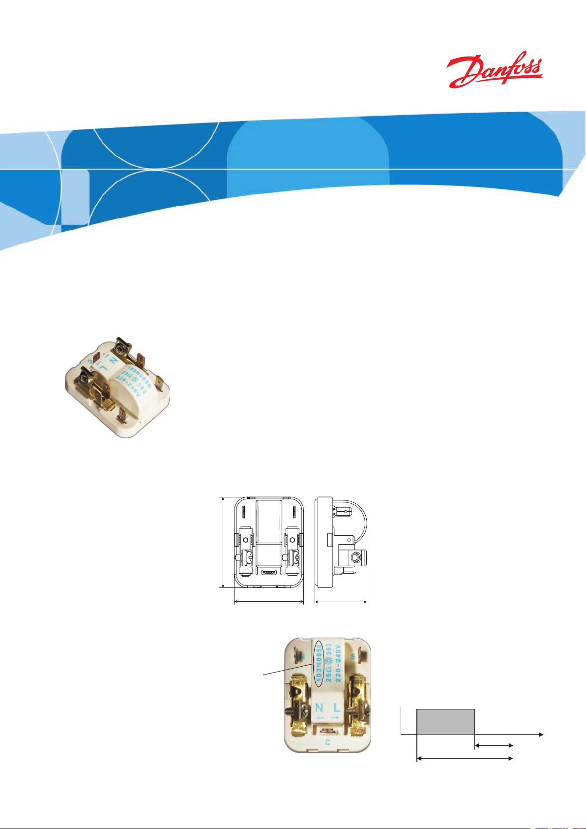
Dimensions
Identification
Code number
103N0050
Functional Description
The main component of the ePTC is
the same PTC pill like in other 220240 V 103N…. Danfoss PTC starters.
Thus the start of the compressor
motor is performed in the same
way. In standard PTC starters the
>2 W energy loss to keep the PTC
heated during compressor operation are not avoidable. In the ePTC
a small electronic circuit cuts off
the current through the PTC short
time after start and thus reduces
the energy loss down to approx
0.4 W. The switch used is a Triac, an
electronic AC switch, controlled by
a timer circuit.
As the timer circuit has a short
reset time and the main PTC cools
down
during compressor operation
already, the full start torque will be
available after approx 6 s compressor off time. However, it is still a
LST starting device, needing full
pressure equalization before start.
Min. On/Off time
of compressor
REFRIGERATION AND
AIR CONDITIONING
Page 2
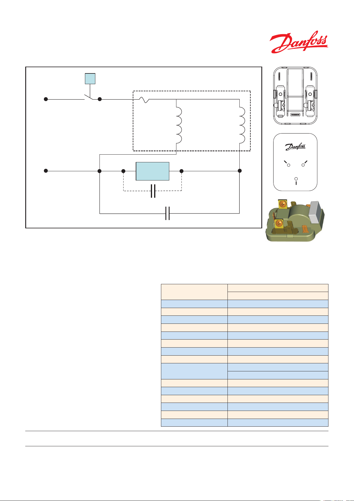
Wiring diagram
M
C
S
N L
C
SN
Front
Rear side
8558
Screw
terminal
Spade
terminal
Spade
terminal
Internal
protecto
r
Auxiliary
winding
Main
windin
g
Supply voltage
220-240 VAC
50 / 60 HZ
Compressor
Internal connection
T
ePTC
Electronic PC
B
L
N
C
N
S
Run capacitor (optional)
Thermostat
Spade
terminal
Spade
terminal
Internal
protecto
r
Auxiliary
winding
Main
windin
g
-240 VAC
Compressor
Internal connection
Screw
terminal
Spade
terminal
Spade
terminal
8557-2
with X2-Cap (optional)
Connections & Terminals
The wiring diagram shows how to make the
connections. The two screw terminals marked
N and L are for supply voltage. The spade on
the L terminal and the spade marked C are for
the thermostat. The spade marked S at the top
right position is internally connected to the
Start (or auxilary) fusite terminal. This spade
together with N is used for a run capacitor. The
spade marked N at the top left position is inter-
nally connected to the Neutral screw terminal.
The spade marked C at the bottom position
is internally connected to the Common fusite
terminal. On the rear side of the ePTC starter
there are three holes. The hole in the bottom
is for the Common fusite terminal on the compressor. The top left hole is for the Start fusite
terminal and the top right hole is for the Main
fusite terminal. The ePTC starter is mounted
with the C spade downwards.
Danfoss can accept no responsibility for possible errors in catalogues, brochures and other printed material. Danfoss reserves the right to alter its products without notice. This also applies to products already
on order provided that such alterations can be made without subsequential changes being necessary in specifications already agreed.
All trademarks in this material are property of the respective companies. Danfoss and the Danfoss logotype are trademarks of Danfoss A/S. All rights reserved.
ePTC with X2-Cap
ePTC with X2-Cap for special Applications
For applications using a mechanical thermostat it can be neccessary to use the ePTC with integrated filter,type X2-Cap.
Technical data
Code number
Nominal supply voltage 220 - 240 V 50/60 Hz
Min. supply voltage 187 V
Max. supply voltage 254 V
Power consumption approx. 0.4 W (after 2 s)
Spade connectors
Cables Temperature resistant up to min. +60°C
Run Capacitor
Thermostats Mechanical or electronic
Ambient temperatures During operation from 0°C to 50°C
During transport from -20°C to 70°C
Enclosure
PTC protection screen Not needed (surface temp. < 82°C)
Approvals EN 60730-1, DEMKO
Radiation
EN 55014-1/EN 61000-3-2/EN 61000-3-3
Immunity EN 50014-2
Declarations
Standard: 103N0050
with X2-Cap:
103N0060
4.8 mm
Optional
IP 00
CE
DEHC.EI.200.B2.02/520N0192 Produced by Danfoss Compressors, DEHC6093, 08.2005
Danfoss Compressors GmbH
Mads-Clausen-Str. 7
D-24939 Flensburg / Germany
compressors.danfoss.com
 Loading...