

Page 1
MAKING MODERN LIVING POSSIBLE
Service Manual
Electrohydraulic Controls Series 51
A7, D7, D8, DA, DC, EE, EP, EQ,
ER, ES, L1, L2, L7
powersolutions.danfoss.com
Page 2

Service Manual Series 51 Electrohydraulic Proportional Controls Service Manual
Revision history Table of revisions
Date Changed Rev
July 2014 Danfoss layout BA
July 2009 First edition AA
2 11009448 • Rev BA • July 2014
Page 3

Service Manual
Contents
Introduction
Pressure measurements
Adjustments
PCOR
Multifunction block
A7, L1, L2, L7 Controls
D7, D8, DA, DC Controls
Series 51 Electrohydraulic Proportional Controls Service Manual
Safety Precautions............................................................................................................................................................................5
Unintended Machine Movement..........................................................................................................................................5
Flammable Cleaning Solvents................................................................................................................................................5
Fluid Under Pressure..................................................................................................................................................................5
Personal Safety.............................................................................................................................................................................5
Hazardous Material.....................................................................................................................................................................5
Symbols used in Danfoss literature............................................................................................................................................6
Overview..............................................................................................................................................................................................6
General Instructions........................................................................................................................................................................ 7
Keep it Clean.................................................................................................................................................................................7
Inspect for System Contamination....................................................................................................................................... 7
Replace the O-rings and Gaskets...........................................................................................................................................7
Lubricate all Moving Parts........................................................................................................................................................7
Torque Procedure....................................................................................................................................................................... 7
General Description.........................................................................................................................................................................7
Overview........................................................................................................................................................................................ 7
Multifunction Block.................................................................................................................................................................... 7
Pressure Compensating OverRide (PCOR) Option..........................................................................................................8
Brake Pressure Defeat (BPD) option.....................................................................................................................................8
Threshold and Ramp Springs...............................................................................................................................................10
Port Locations and Gauge Installation...................................................................................................................................11
Threshold Setting...........................................................................................................................................................................12
Checking Threshold Setting................................................................................................................................................. 12
Adjusting Threshold Setting.................................................................................................................................................12
Pressure compensator Override (PCOR) setting.................................................................................................................13
PCOR Adjustment.....................................................................................................................................................................13
Checking PCOR Setting on a Test Stand.......................................................................................................................... 14
Adjusting the PCOR Setting..................................................................................................................................................14
Optional PCOR Housing Repair.................................................................................................................................................15
Disassembly................................................................................................................................................................................15
Inspection....................................................................................................................................................................................15
Assembly......................................................................................................................................................................................15
Optional Multifunction Block Repair.......................................................................................................................................17
Disassembly................................................................................................................................................................................17
Inspection....................................................................................................................................................................................18
Assembly......................................................................................................................................................................................18
Operation .........................................................................................................................................................................................19
General Description.................................................................................................................................................................19
Proportional Solenoid.............................................................................................................................................................19
Check Valve.................................................................................................................................................................................19
Schematic......................................................................................................................................................................................... 21
Repair..................................................................................................................................................................................................21
Removing Solenoid..................................................................................................................................................................21
Disassembly................................................................................................................................................................................21
Inspection....................................................................................................................................................................................23
Assembly......................................................................................................................................................................................23
Solenoid Assembly...................................................................................................................................................................23
Operation..........................................................................................................................................................................................24
General Description.................................................................................................................................................................24
11009448 • Rev BA • July 2014 3
Page 4

Service Manual
Contents
EE Control
EP, EQ, ER, ES Controls
Series 51 Electrohydraulic Proportional Controls Service Manual
Pressure-Reducing Valve....................................................................................................................................................... 24
Schematic......................................................................................................................................................................................... 25
Repair..................................................................................................................................................................................................26
Disassembly................................................................................................................................................................................26
Inspection....................................................................................................................................................................................27
Assembly......................................................................................................................................................................................27
Operation..........................................................................................................................................................................................29
General Description.................................................................................................................................................................29
Repair..................................................................................................................................................................................................30
Disassembly................................................................................................................................................................................30
Inspection....................................................................................................................................................................................31
Assembly......................................................................................................................................................................................31
Operation..........................................................................................................................................................................................33
General Description.................................................................................................................................................................33
Schematics........................................................................................................................................................................................34
Definitions...................................................................................................................................................................................35
Repair..................................................................................................................................................................................................35
Control Housing Disassembly..............................................................................................................................................35
PCOR Disassembly....................................................................................................................................................................36
Multifunction Block Disassembly........................................................................................................................................37
Control Orifices..........................................................................................................................................................................38
Inspection....................................................................................................................................................................................39
Multifunction Block Assembly............................................................................................................................................. 39
Inspection....................................................................................................................................................................................40
PCOR Assembly......................................................................................................................................................................... 40
Control Housing Assembly....................................................................................................................................................41
4 11009448 • Rev BA • July 2014
Page 5

W
W
W
W
W
Service Manual
Introduction
Safety Precautions
Series 51 Electrohydraulic Proportional Controls Service Manual
Always consider safety precautions before beginning a service procedure. Protect yourself and others
from injury. Take the following general precautions whenever servicing a hydraulic system.
Unintended Machine Movement
Warning
Unintended movement of the machine or mechanism may cause injury to the technician or bystanders.
To protect against unintended movement, secure the machine or disable/disconnect the mechanism
while servicing.
Flammable Cleaning Solvents
Warning
Some cleaning solvents are flammable. To avoid possible fire, do not use cleaning solvents in an area
where a source of ignition may be present.
Fluid Under Pressure
Warning
Escaping hydraulic fluid under pressure can have sufficient force to penetrate your skin causing serious
injury and/or infection. This fluid may also be hot enough to cause burns. Use caution when dealing with
hydraulic fluid under pressure. Relieve pressure in the system before removing hoses, fittings, gauges, or
components. Never use your hand or any other body part to check for leaks in a pressurized line. Seek
medical attention immediately if you are cut by hydraulic fluid.
Personal Safety
Warning
Protect yourself from injury. Use proper safety equipment, including safety glasses, at all times.
Hazardous Material
Warning
Hydraulic fluid contains hazardous material. Avoid prolonged contact with hydraulic fluid. Always
dispose of used hydraulic fluid according to state, and federal environmental regulations.
11009448 • Rev BA • July 2014 5
Page 6
Service Manual
Series 51 Electrohydraulic Proportional Controls Service Manual
Introduction
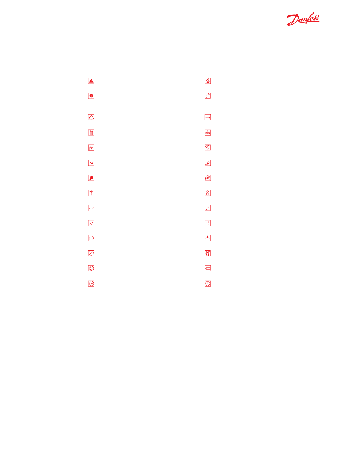
Symbols used in Danfoss literature
WARNING may result in injury Tip, helpful suggestion
CAUTION may result in damage to product or
property
Reusable part Apply grease / petroleum jelly
Non-reusable part, use a new part Apply locking compound
Non-removable item Inspect for wear or damage
Option - either part may exist Clean area or part
Superseded - parts are not interchangeable Be careful not to scratch or damage
Measurement required Note correct orientation
Flatness specification Mark orientation for reinstallation
Parallelism specification Torque specification
External hex head Press in - press fit
Internal hex head Pull out with tool – press fit
Lubricate with hydraulic fluid
Overview
Torx head Cover splines with installation sleeve
O-ring boss port Pressure measurement/gauge location or
specification
The symbols above appear in the illustrations and text of this manual. They are intended to communicate
helpful information at the point where it is most useful to the reader. In most instances, the appearance
of the symbol itself denotes its meaning. The legend above defines each symbol and explains its purpose.
This manual includes information for the installation, maintenance, and minor repair of Series 51
electrohydraulic proportional controls. It includes a description of the unit and its individual components,
and minor repair procedures.
Performing minor repairs may require removal of the unit from the vehicle/machine. Thoroughly clean
the unit before beginning maintenance, or repair activities. Since dirt and contamination are the greatest
enemies of any type of hydraulic equipment, strictly follow cleanliness requirements. This is especially
important when changing the system filter and when removing hoses or plumbing.
A worldwide network of Danfoss Global Service Partners is available for major repairs. Danfoss Global
Service Partners are trained by the factory and certified on a regular basis. You can locate your nearest
Global Service Partner using the distributor locator at www.powersolutionsdanfoss.com. Click on the
Sales and Service link.
6 11009448 • Rev BA • July 2014
Page 7

Service Manual
Introduction
General Instructions
Series 51 Electrohydraulic Proportional Controls Service Manual
Keep it Clean
You can complete many repairs or adjustments without removing the unit from the machine, if the unit is
accessible and you can thoroughly clean it before beginning any procedures.
Cleanliness is a primary means of assuring satisfactory motor life on either new or repaired units. Clean
the outside of the motor thoroughly before disassembly. Take care to avoid contamination of the system
ports. Cleaning parts with a clean solvent wash and air drying is usually adequate.
As with any precision equipment, keep all parts free of foreign materials and chemicals. Protect all
exposed sealing surfaces and open cavities from damage and foreign material. Cap all hoses after
removal, and plug all open ports. Cover any unattended parts with a protective layer of plastic.
Inspect for System Contamination
Inspect the motor for signs of system contamination. If you find contamination, fully disassemble, clean
and inspect all components of the motor.
Replace the O-rings and Gaskets
Replace all O-rings and gaskets. Discard them only after you make certain that you have the correct
replacement parts. Lightly lubricate all O-rings with clean petroleum jelly before assembly.
General Description
Lubricate all Moving Parts
During reassembly, coat all moving parts with a film of clean hydraulic oil. This helps lubricate the
surfaces during start-up.
For fluid quality requirements, refer to Hydraulic Fluids and Lubricants, Technical Information 520L0463.
Torque Procedure
During reassembly, cross torque all retaining screws to the given value. Do not overtorque.
Overview
Electrohydraulic proportional controls infinitely vary motor displacement between maximum and
minimum. They do this by shifting the 4-way valve. The spool position shifts with an
electric pressure-reducing valve. It varies signal pressure on the end of the 4-way valve (D7, D8
•
controls), or
electrically varied differential pressure on the ends of a piston connected to the 4‑way valve (EP, EQ,
•
ER, ES, ED, EE controls), or
electric proportional solenoid acting directly on the 4-way valve (A7, L1, L2, L7 controls).
•
Multifunction Block
Some of the electrohydraulic proportional controls are used in conjunction with the multifunction block.
The multifunction block is a manifold with a shuttle valve that routes high loop (system pressure) from
port A or B to the 4-way valve while routing the low loop (stystem pressure) to the PCOR valve. The 4-way
valve directs this pressure to the ends of the servo piston to change displacement. The multifunction
block may also provides the pressure compensating override (PCOR) option that regulates system
pressure.
11009448 • Rev BA • July 2014 7
Page 8
N20
N16
N27
N23
N27
N18
N14
N29
N23
P101 906
Service Manual
Introduction
Series 51 Electrohydraulic Proportional Controls Service Manual
Pressure Compensating OverRide (PCOR) Option
The PCOR function allows the motor to match its displacement to the system load. The PCOR overrides
the control command allowing the motor to increase displacement when system pressure reaches a set
level due to load. This permits the motor to regulate system pressure by modulating the displacement of
the rotating group. As displacement increases, so does available torque while output speed decreases
and system pressure remains nearly constant at the PCOR setting.
The PCOR setting pressure is adjustable from 110 to 370 bar [1595 to 5365 psi]. Optional orifices at
locations T4, T5, T6, U6, and U7 regulate the speed of the PCOR operation.
PCOR
Brake Pressure Defeat (BPD) option
The PCOR function can be equipped with a brake pressure defeat (BPD) option that defeats the PCOR
operation during dynamic braking. A shuttle spool in the multifunction block in front of the PCOR valve
directs only acceleration system pressure to the PCOR. During deceleration, the high dynamic braking
pressure is blocked from the PCOR. This limits rapid and uncontrolled pressures or engine over-speeding
while the vehicle/machine is slowing down. External hydraulic signal pressures fed to ports XA or XB are
essential to operate the BPD spool. PCOR operation on one-system pressure side is also an option.
EP, EQ Electrohydraulic Proportional Control with Pressure Compensator and Hydraulic Brake Pressure Defeat.
8 11009448 • Rev BA • July 2014
Page 9
M4
M3
M1
L1
L2
M5
M2
M8M7
X1
B
XB XA
A
Max.
displ.
P101 907
PCOR
Multifunction Block
Control
BPD
Shuttle valve
Brake defeat spool
P106 431E
PCOR spool
PCOR adjuster
Service Manual
Introduction
Series 51 Electrohydraulic Proportional Controls Service Manual
BPD
BPD option
11009448 • Rev BA • July 2014 9
Page 10
J50
S100
(includes J30)
P101 909
J20
S10
S10*
J10*
S10*
S20
J30
160cc and 250cc
80cc and 110cc
Service Manual Series 51 Electrohydraulic Proportional Controls Service Manual
Introduction
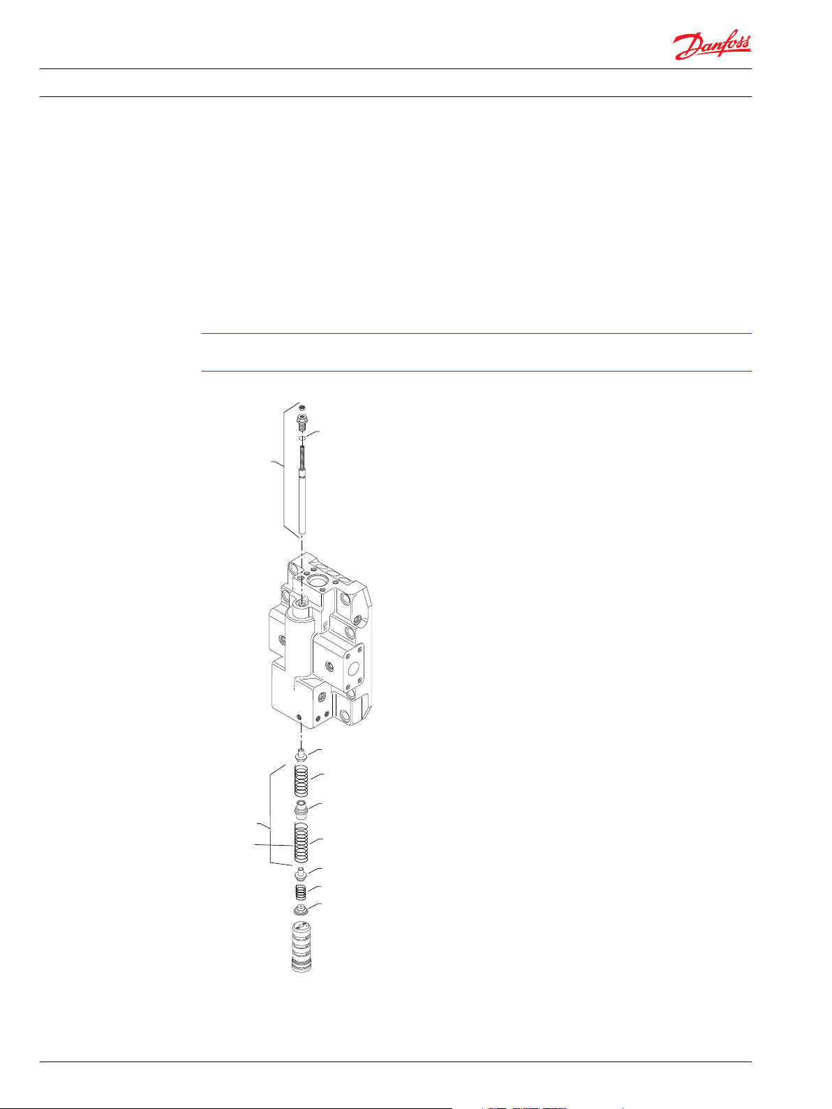
Threshold and Ramp Springs
A threshold spring and ramp spring(s) act on the opposite end of the 4-way valve. The threshold
adjustment screw (S100) varies the threshold spring force. This changes the signal current required to
move the 4-way valve and start the change in displacement. The S10* ramp spring(s)—two used in 160 cc
and 250 cc motors and one used in 80 cc and 110 cc motors—increase the force on the 4-way valve as
the servo piston moves toward minimum displacement. This provides a motor displacement
proportional to the variable input signal current.
The control-operating threshold (the signal current or force when the motor starts to shift) is adjustable.
Adjust it using the S100 adjusting screw in the motor’s end cap.
Changing ramp spring force requires replacing the springs. There are several spring rates available.
Optional orifices may be installed at several locations to regulate shift speed. Refer to the Model Code for
your motor for details.
Ramp Springs
10 11009448 • Rev BA • July 2014
Page 11
M2
Y
side port
M4
M1
Main ports A+B
M5
M7
L2
M3
L1
M1
M5
W
W
M3
Y
P101 204E
System pressure A+B
Guage port M1+M2
Axial port
Main
port B
Main
port A
M5
M3
M4
Y
W
Y
Axial port
P101 204E
M5
Service Manual Series 51 Electrohydraulic Proportional Controls Service Manual
Pressure measurements
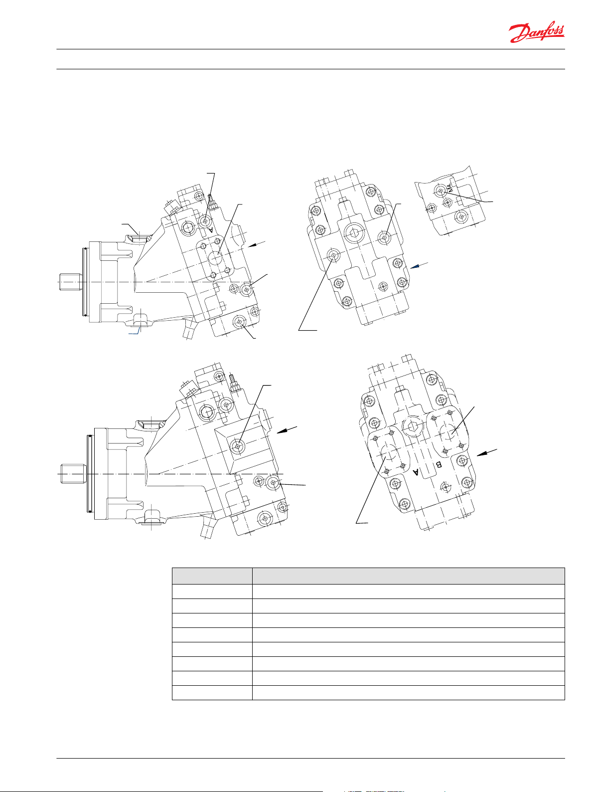
Port Locations and Gauge Installation
Series 51 Motors
Legend
Abbreviation Definition
L1 Case drain; (1-5/16-12UNF)
L2 Alternate case drain: (1-5/16-12UNF)
M1 Gauge port: system pressure A (9/16-18UNF)
M2 Gauge port: system pressure B (9/16-18UNF)
M3 Gauge port: servo pressure min. angle (9/16-18UNF)
M4, Gauge port: servo pressure max. angle (9/16-18UNF)
M5 Gauge port: servo supply pressure (9/16-18UNF)
M7 Control pressure port (9/16-18UNF)
11009448 • Rev BA • July 2014 11
Page 12

Service Manual
Adjustments
Threshold Setting
Series 51 Electrohydraulic Proportional Controls Service Manual
Checking Threshold Setting
1. Install a 50 bar [600 psi] gauge at port M3 to read minimum servo pressure.
2. Install a 50 bar [600 psi] gauge at port M4 to read maximum servo pressure.
3. Install meter to read signal current.
4. Increase the signal current to the proper setting.
The pressure at port M3 should rise to about 100 psi [6.89 bar] higher than the pressure at port M4.
This causes the servo piston to start to move toward minimum position. Signal current at this point is
the threshold setting.
On a test stand, increase signal current until the flow from the motor begins to decrease. The signal
current at this point is the threshold setting.
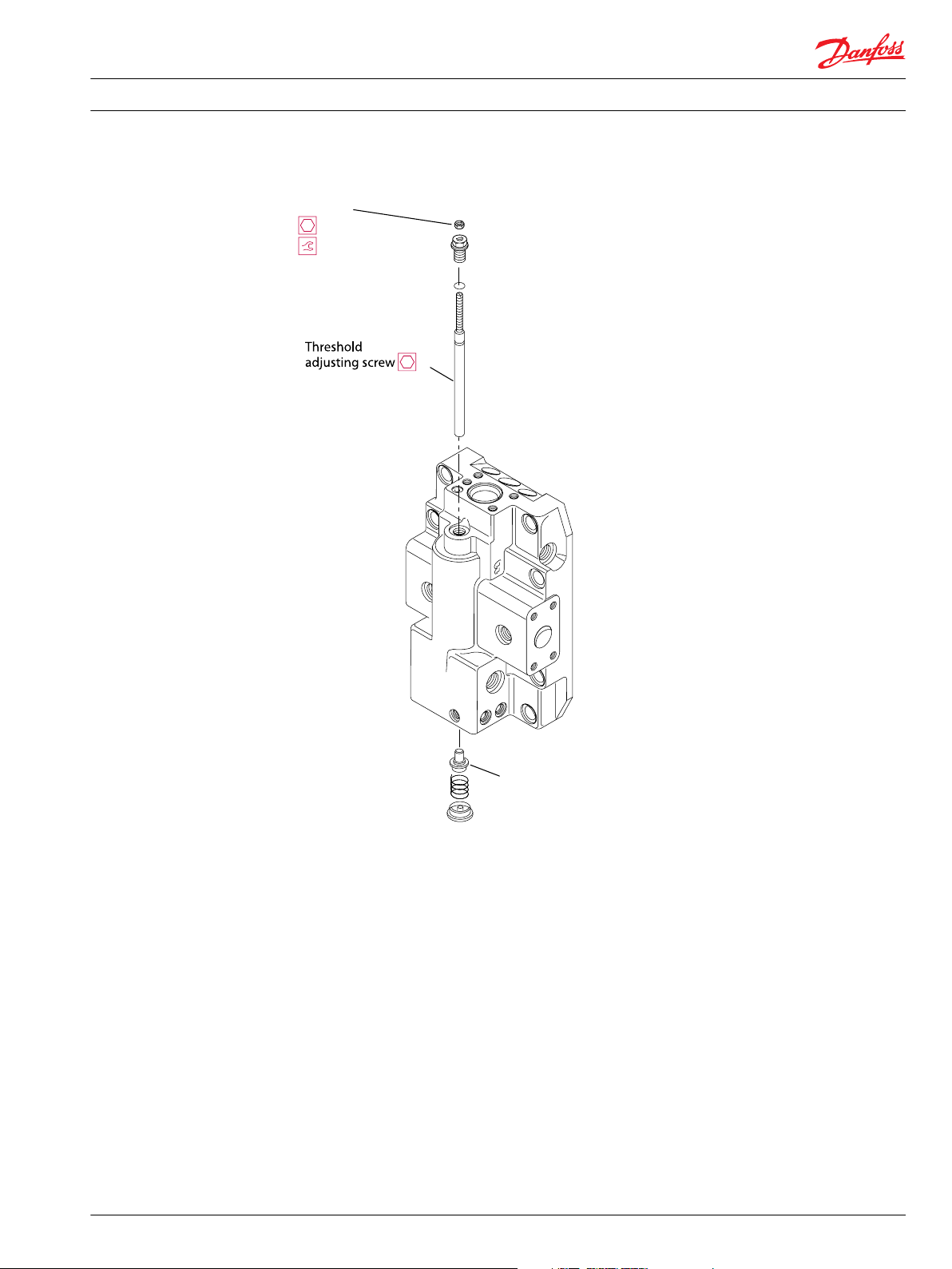
Adjusting Threshold Setting
1. Using a 10 mm wrench, loosen the locknut on the adjusting screw.
2. Using a 3 mm internal hex wrench turn the adjusting screw:
Clockwise (cw) to increase the setting
•
Counterclockwise (ccw) to decrease the setting.
•
3. While holding the position of the adjustment screw:
tighten the locknut
•
using a 10 mm wrench torque the locknut to 9 N•m [6.6 lbf•ft].
•
12 11009448 • Rev BA • July 2014
Page 13
Spring seat
P101 911
Locknut
10 mm
9 Nm [6.6 lbf•ft]
Service Manual
Adjustments
Series 51 Electrohydraulic Proportional Controls Service Manual
Locknut and Threshold
Pressure compensator Override (PCOR) setting
PCOR Adjustment
In order to measure and adjust the start pressure setting for the PCOR function:
1. Install a 600 bar [10000 psi] gauge at port M1 or M2 or M5 to read high system pressure.
2. Install a 600 bar [10000 psi] gauge at port M3 to read minimum servo pressure.
3. Lock the motor shaft from moving by:
Applying the park brake, apply an extreme load, or
•
Position the machine against an immovable object, or
•
Other means to hold the machine.
•
4. Start the prime mover. Operate at medium RPM.
5. Stroke the pump very slowly to gradually increase the system pressure.
11009448 • Rev BA • July 2014 13
Page 14

W
Service Manual Series 51 Electrohydraulic Proportional Controls Service Manual
Adjustments
An alternate method to slowly increase the system pressure is to use the pump’s pressure limiter (PL)
valve. Lower the PL setting below the PCOR setting. Stroke the pump to about one-fourth
displacement. Raise the PL setting slowly to increase system pressure until pressure at the M3 port
drops down. System pressure at this point is the PCOR setting. Adjust the PL back to its proper setting
after checking the PCOR setting.
6. Increase system pressure until pressure at port M3 drops down, system pressure at this point is the
PCOR setting.
Checking PCOR Setting on a Test Stand
Increase system pressure until the system flow begins to increase. System pressure at this point is the
PCOR setting.
Warning
System pressure may increase rapidly when flow increases.
Adjusting the PCOR Setting
For PCOR valves mounted on a Multiblock; use a 1-1/16 in. wrench to loosen the lock nut on the
adjusting screw. Using a large screw driver or a 13 mm wrench turn the adjusting screw clockwise to
increase pressure setting or counter clockwise to lower pressure setting. One turn of the adjusting
screw changes the setting approximately 69 bar [1000 psi].
14 11009448 • Rev BA • July 2014
Page 15

N82
N29
N20
N14
N18
Z00
N87
U6
U7
N24P
P106 384E
N23
N27
N27
N16J
Service Manual
PCOR
Optional PCOR Housing Repair
Series 51 Electrohydraulic Proportional Controls Service Manual
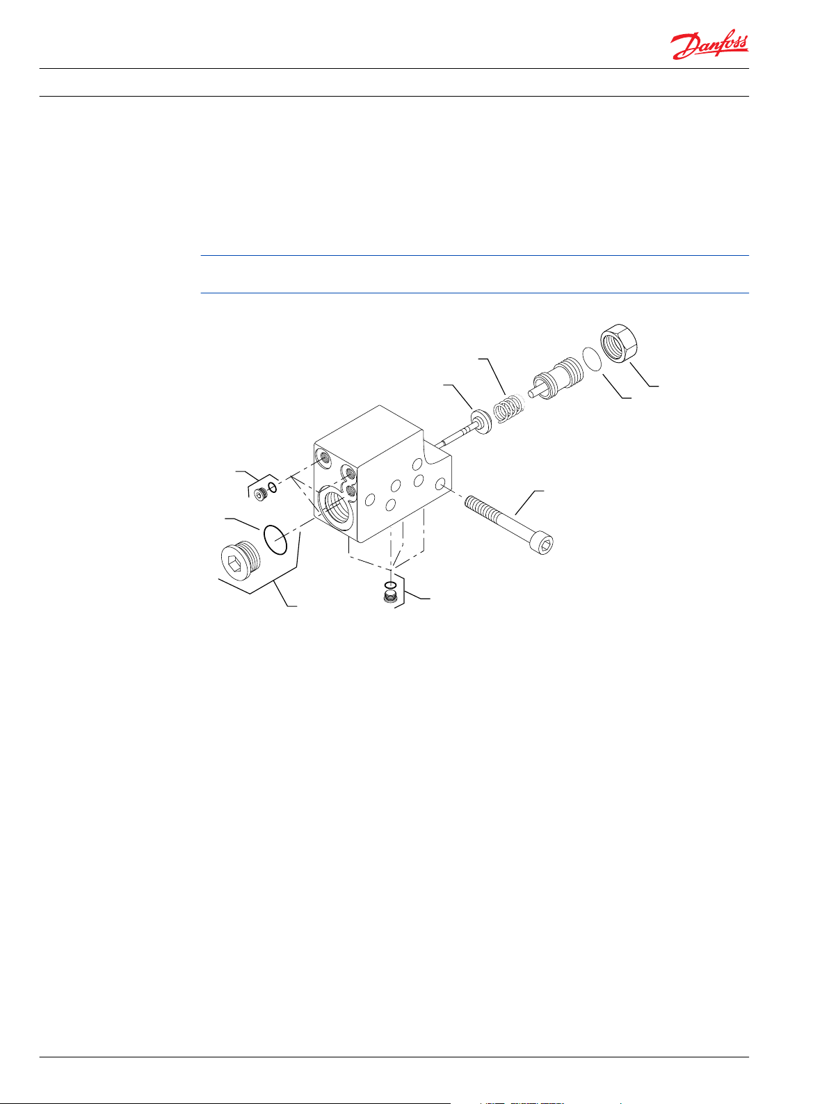
Disassembly
1. Remove plugs (N27). Remove and discard O-rings (N27A).
2. Using a 1 inch hex wrench, remove plug (N23). Remove and discard O-ring (N23A).
3. Remove locknut (N14).
4. Remove adjustment plug (Z00). Remove and discard O-ring (N16J).
5. Remove spring (N18).
6. Remove spool and spring guide assembly (N20).
7. Remove screws (N29).
8. Remove and discard O-rings (N24P, N82).
9. If present, remove orifices (U6, U7).
PCOR
Legend
Item Wrench size Torque
N27 1/8 inch internal hex 7 Nm [4 lbf•ft]
N23 1 inch 40 Nm [30 lbf•ft]
U6, U7 3 mm internal hex 6 Nm [4 lbf•ft]
N29 5 mm internal hex 16 Nm [12 lbf•ft]
N14 1-5/16 inch N/A
Inspection
Clean and inspect components for damage or foreign material. Replace damaged parts.
Assembly
1. If previously removed, Use a 3mm internal hex wrench to install orifices (U6, U7). Torque to 6 N•m [4
lbf•ft].
2. Using petroleum jelly to retain them, install new interface O-rings (N24P, N82).
11009448 • Rev BA • July 2014 15
Page 16

Service Manual Series 51 Electrohydraulic Proportional Controls Service Manual
PCOR
3. Position PCOR on multiblock. Install screws (N29). Torque using a 5 mm internal hex wrench to 16
N•m [12 lbf•ft].
4. Lubricate and install spool and spring guide assembly (N20).
5. Install spring (N18) to cavity.
6. Lubricate and install new O-ring (N16J). Install adjustment plug (Z00).
7. Using a 1-1/16 inch hex wrench, install locknut (N14). Do not torque until after PCOR adjustment.
Refer to PCOR Adjustment on page 13 for instructions.
8. Lubricate and install a new O-ring (N23A). Using a 1 inch hex wrench, install plug (N23). Torque to 40
N•m [30 lbf•ft].
9. Lubricate and install new O-rings (N27A). Using a 1/8 inch internal hex wrench, install and torque
plugs (N27) to 7 N•m [4 lbf•ft].
16 11009448 • Rev BA • July 2014
Page 17

G42
G42
G38
G38
G38
G36
N52
N30
N1A1
N58
P101210
N27
N27
N27
N27
N26
N26
N240
Service Manual Series 51 Electrohydraulic Proportional Controls Service Manual
Multifunction block
Optional Multifunction Block Repair
Disassembly
1. Using a ¼ inch internal hex wrench, remove plugs (N26). Remove and discard O-rings (N26A).
2. Remove the spool (N30).
3. Using a 1/8 inch internal hex wrench, remove plugs (N27). Remove and discard O-rings (N27A).
4. Remove screws (N58).
5. Remove the multifunction block (N1A1).
6. Remove and discard the O-rings (G36, G38, G42) or gasket (N240).
7. If present, remove and discard screens (N52).
E*, F* Control
Legend
Item Wrench size Torque
N27 1/8 inch internal hex 7 Nm [4 lbf•ft]
N26 1/4 inch internal hex 37 Nm [28 lbf•ft]
11009448 • Rev BA • July 2014 17
Page 18

Service Manual Series 51 Electrohydraulic Proportional Controls Service Manual
Multifunction block
Legend (continued)
Item Wrench size Torque
N58
80cc, 110cc
N58
160cc, 250cc
Inspection
Clean and inspect components for damage or foreign material. Replace damaged parts.
Assembly
1. Lubricate and install new O-rings (N27A). Install plugs (N27) using a 1/8 inch internal hex wrench.
Torque to 7 N•m [4 lbf•ft].
2. Using petroleum jelly to retain them, install new interface O-rings (G36, G38, G42) or gasket (N240).
3. Position the multifunction block on the endcap. Install screws (N58). Torque screws as shown in the
table.
4. Lubricate and install the double-resolver spool (N30). Spool is symetrical, either end first.
5. Lubricate and install new O-rings (N26A). Using a 1/4 inch internal hex wrench, install plugs (N26).
Torque to 37 N•m [28 lbf•ft].
8 mm internal hex 78 Nm [58 lbf•ft]
10 mm internal hex 110 Nm [81 lbf•ft]
18 11009448 • Rev BA • July 2014
Page 19

Service Manual
A7, L1, L2, L7 Controls
Operation
Series 51 Electrohydraulic Proportional Controls Service Manual
General Description
The A7, L1, L2, L7 controls consist of a ported housing mounted directly on the end cap. It contains a
check valve. A direct acting proportional solenoid, with a pushpin, is mounted onto the housing. This
solenoid is high-current. It has an input range of 440 to 1290 mA (12V) or 220 to 645 mA (24v). These
controls are not available with pressure compensator override.
Proportional Solenoid
The proportional solenoid, through the pushpin, presses directly against the 4‑way valve. With signal
current below the threshold setting, the motor defaults to maximum displacement. An increase in signal
current above the threshold setting, shifts motor displacement steplessly from maximum to minimum.
Connector Oder Code
Order code Volts Connector
A7 12v AMP Junior Timer
L1 12v DIN
L2 24v DIN
L7 12v AMP Junior Timer
Check Valve
The check valve resolves which system port (A or B) is higher pressure. It routes this higher pressure to
the 4-way valve, as servo supply pressure, to power the servo piston.
11009448 • Rev BA • July 2014 19
Page 20

F32
F324
M1
M18
M18A
M10
M16
M16A
M22
G38
G42
G38
G42
G36
M18
M12
P101 908
Service Manual Series 51 Electrohydraulic Proportional Controls Service Manual
A7, L1, L2, L7 Controls
A7, L1, L2, L7 controls
20 11009448 • Rev BA • July 2014
Page 21

M4
M3
M1
L1
L2
M5
B
M2
Max.
displ.
P101 904
Check
valve
Loop
flush
Solenoid
Service Manual
A7, L1, L2, L7 Controls
Schematic
Series 51 Electrohydraulic Proportional Controls Service Manual
A7, L1, L2, L7 Schematic
Repair
Removing Solenoid
Solenoid (M1) is available as complete assembly only. Do not remove the solenoid unless it is being
replaced.
If replacing the solenoid (M1); remove plastic nut, remove coil, and use a 3/4 inch thin wrench to
remove solenoid.
Disassembly
1. Using a 1/8-inch internal hex wrench, remove plugs (M18).
2. Remove and discard O-rings (M18A).
11009448 • Rev BA • July 2014 21
Page 22

F32
M18
M10
M16A
M22
G38
G42
G38
G42
M18
M12
M16
M1
M1 coil
Plastic
nut
Solenoid
stem
O-ring M1A
O-ring
P101 915
G420
Service Manual
A7, L1, L2, L7 Controls
Series 51 Electrohydraulic Proportional Controls Service Manual
Controls
Legend
Item Wrench size Torque
M22
(80, 110)
M22
(160, 1250)
Item Wrench size Torque
M16 1/4 internal hex 37 Nm [27 lbf•ft]
M18 1/8 internal hex 6 Nm [4 lbf•ft]
M12 5 mm internal hex 11 Nm [8 lbf•ft]
3. Using a 1/4-inch internal hex wrench, remove the plug assembly (M16).
4. Remove and discard O-ring (M16A).
22 11009448 • Rev BA • July 2014
8 mm internal hex 78 Nm [58 lbf•ft]
10 mm internal hex 110 Nm [81 lbf•ft]
Page 23

C
Service Manual
A7, L1, L2, L7 Controls
Series 51 Electrohydraulic Proportional Controls Service Manual
5. Using a 5mm internal hex wrench remove orifice (M12)
6. Remove check-valve assembly (M10).
If necessary, tap the housing on a hard surface to remove the check valve assembly.
7. Remove screws (M22)
8. Remove control housing. Remove and discard O rings (G36, G38, and G42) or gasket (G420).
9. Remove spool (F32).
Caution
Read BLN-10181 for repair instructions for the F32 4-way valve, threshold spring, and ramp spring
components, if their repair is necessary
10. Remove and discard O-rings (F324).
Inspection
1. Inspect the housing and spools for wear, damage or foreign material.
2. Check internal passages for contamination and clean them if necessary.
Assembly
1. Lubricate and install O-rings (F324).
2. Install valve (F32).
3. Using petroleum jelly, lubricate and install new O-rings (G38, G42, G36), or install gasket (N240).
4. Position control on end cap.
5. Install screws (M22). Torque per listing in table.
6. Lubricate and install new O-rings (M18A).
7. Install plugs (M18). Using a 1/8-inch internal hex wrench torque plugs to 6 N•m [4 lbf•ft].
8. Install the check valve assembly (M10).
9. Install orifice (M12). Using a 5mm internal hex, torque orifice to 11 N•m [8 lbf•ft].
10. Install new O-ring (M16A).
11. Install the plug (M16). Using a 1/4-inch internal hex wrench torque the plug to 37 N•m [27 lbf•ft].
Solenoid Assembly
1. Lubricate and install O-ring (M1A). Install solenoid.
2. Using a 3/4 inch thin wrench, torque solenoid to 47 Nm [35 lbf•ft].
3. Install coil with O-rings.
4. Install plastic nut. Tighten by hand.
11009448 • Rev BA • July 2014 23
Page 24

F32
M15
M1
T6
T4
M24
G38
G42
G38
G42
M23
M23A
M24
M22
M24
M24A
M22A
M24
M151
M150
F324
G36
M16
M14
Z*
N32
M21
M20
M18
T7
P101 919
G420
Service Manual
D7, D8, DA, DC Controls
Operation
Series 51 Electrohydraulic Proportional Controls Service Manual
General Description
The D7 and D8 controls consist of a ported housing with an electric pressure-reducing valve, a pressure
compensator override valve (PCOR), and an optional hydraulic brake pressure defeat (BPD) spool. For
these controls, there must be external servo supply pressure fed to the M5 port (25 bar [363 psi]
minimum, 50 bar [725 psi] maximum).
DA and DC controls include an electric brake pressure defeat option.
Pressure-Reducing Valve
The pressure-reducing valve uses servo supply pressure for signal pressure. It varies this pressure
electrically and feeds it to the end of the F32 4-way valve. With signal current below the threshold setting,
the motor defaults to maximum displacement. An increase in signal current shifts the motor
displacement from maximum to minimum.
D7, D8 Control
24 11009448 • Rev BA • July 2014
This pressure-reducing valve coil is high current. It has an input range of 640 mA to 1188 mA (12v) or 320
mA to 594 mA (24v).
The D7 solenoid is 12 volt. The D8 solenoid is 24 volt. Both are fitted with AMP Junior Timer connectors.
Page 25

M4
M3
M1
L1
L2
X3
M2
M7
B
XB
XA
A
Max.
displ.
P101 905
BPD
PCOR
Pressure reducing
valve
n
T2
T3
T1
T7 T8
Vg
Maximum
B
U5
A
L2
M4 M3
N
M1
L1
M2
X3 (M5)
P107 875E
A1
B1
U7T5
M7
BPD
PCOR
Pressure reducing
valve
Service Manual
D7, D8, DA, DC Controls
Schematic
Series 51 Electrohydraulic Proportional Controls Service Manual
D7, D8 Schematic
DA, DC Schematic
11009448 • Rev BA • July 2014 25
Page 26

F32
M1
T6
T4
M24
G38
G42
G38
G42
M23A
M24
M24
M24A
M22A
M24
F324
G36
M14
Z*
N32
M21
M20
M18
P101 928
G420
Service Manual Series 51 Electrohydraulic Proportional Controls Service Manual
D7, D8, DA, DC Controls
Repair
Disassembly
Solenoid (M1) is available as complete assembly only. Do not remove the solenoid unless it is being
replaced.
1. Using a 3 mm internal hex wrench remove screws (M15).
2. Remove solenoid M1.
3. Using a 1 1/16-inch wrench remove nut (M14).
4. Remove and discard O-ring (M16).
D7, D8 Control
Legend
Item Wrench size Torque
M151
(80, 110 cc)
M150
(160, 250 cc)
U7 3 mm internal hex 6 Nm [4 lbf•ft]
8 mm internal hex 78 Nm [58 lbf•ft]
10 mm internal hex 110 Nm [81 lbf•ft]
26 11009448 • Rev BA • July 2014
Page 27

C
Service Manual
D7, D8, DA, DC Controls
Series 51 Electrohydraulic Proportional Controls Service Manual
Legend (continued)
Item Wrench size Torque
M24, N84 1/8 internal hex 6 Nm [4 lbf•ft]
Item Wrench size Torque
M22 1/4 internal hex 37 Nm [28 lbf•ft]
M15 3 mm internal hex 3.7 Nm [2.7 lbf•ft]
M18 1/8 internal hex 6 Nm [4.5 lbf•ft]
M14 1-1/16 inch 52 Nm [38 lbf•ft]
M23 1 inch 40Nm [30 lbf•ft]
Z* 13 mm N/A
5. Using a 13 mm wrench remove the Z* adjuster.
6. Remove spring (M18). Remove the PCOR spool (M20).
7. Don’t remove PCOR valve bushing (M21).
8. Using a 1/8-inch internal hex wrench, remove plugs (M24).
9. Remove and discard O-rings (M24A).
10. If necessary, use a 3 mm internal hex wrench to remove and clean orifices T4, and T6.
11. Using a 1-inch wrench remove plug (M23). Remove and discard O-ring (M23A).
12. Using a 1/4-inch internal hex wrench remove plug (M22). Remove and discard O-ring (M22A).
13. Remove spool (N32).
14. Remove screws (M150 and M151). Refer to table for wrench sizes.
15. Remove control assembly from end cap.
16. Remove and discard O-rings (G36, G38, and G42) or gasket (G420).
17. Remove the 4-way valve assembly (F32). Discard O-rings (F324).
Caution
Read BLN-10181 for minor repair instructions for the F32 4-way valve, threshold spring, and ramp
spring components, if their repair is necessary
Inspection
1. Inspect the housing and spools for wear, damage or foreign material.
2. Check internal passages for contamination and clean them if necessary.
Assembly
1. Lubricate and install new O-rings (F324). Install 4-way valve assembly (F32)
2. Using a 3 mm internal hex wrench, install and torque orifices (T4, and T6) to 2.8 N•m [2.1 lbf•ft].
3. Using petroleum jelly to retain them, install the new O-rings (G36, G38, and G42) or gasket (G420).
4. Position control housing on endcap.
5. Install screws (M150 and M151). Refer to table for wrench sizes and torques.
6. Install spool (N32).
7. Lubricate and install new O-rings (M22A). Install plug (M22).
8. Using a 1/4-inch internal hex wrench, torque plug (M22) to 37 N•m [27 lbf•ft].
9. Lubricate and install a new O-ring (M23A). Install plug (M23).
10. Using a 1-inch wrench, torque plug (M23) to 40 N•m [30 lbf•ft].
11. Lubricate and install new O-rings (M24A). Install plugs (M24).
11009448 • Rev BA • July 2014 27
Page 28

Service Manual Series 51 Electrohydraulic Proportional Controls Service Manual
D7, D8, DA, DC Controls
12. Using a 1/8-inch internal hex wrench, torque plugs (M24) to 6 N•m [4 lbf•ft].
13. Install PCOR spool (M20). Install spring (M18).
14. Using a 13 mm wrench, install the Z* adjuster.
15. Lubricate and install O-ring (M16). Install nut (M14). Do not torque nut (M14).
16. Before returning to normal operation, readjust the PC setting (see p. 15).
17. Install solenoid M1. Install screws (M15).
18. Using a 3 mm internal hex wrench torque screws (M15) to 2.8 N•m [2.1 lbf•ft].
28 11009448 • Rev BA • July 2014
Page 29

max
disp.
M2
B
L1
M1
A
L2
M4
M3
B1
A1
M5
M7 M8
X1
T1
T6
T2
T3
T7 T8
T4
P101 930
Service Manual
EE Control
Operation
Series 51 Electrohydraulic Proportional Controls Service Manual
General Description
The EE controls consist of a ported housing mounted directly on the end cap. The ported housing has a
piston and a pushpin that contact the 4-way valve (F32), and a ball-check valve. A pressure control pilot
(PCP) is mounted on the control housing.
The PCP produces a differential output pressure. It’s proportional to the applied electrical input signal.
Differential pressure is fed to the piston ends. When differential pressure reaches the preset threshold
force on the piston it causes the 4-way valve (F32) to move. The 4-way valve ports servo supply pressure
to the servo piston. This changes the motor’s displacement.
Circuit Diagram for Motor with EE Control
Ports:
A, B = Main pressure lines
L1, L2 = Drain lines
M1, M2 = Gauge port for A and B
M3, M4 = Gauge port servo pressure
X3 (M5) = Servo pressure supply
M7 = Gauge port control pressure
XA, XB = Control pressure ports hydraulic brake pressure defeat
T1, T2, T3, T4, T6, T7, T8, U7= Optional orifices
N = Speed sensor
EE controls have a metri-pack connector.
11009448 • Rev BA • July 2014 29
Page 30

M18
M16H
M48A
M14
M12
M30
M47
M46
M48
P101 934
M26
M25
M24
M22
M20
F32
M10
G420
Service Manual Series 51 Electrohydraulic Proportional Controls Service Manual
EE Control
Repair
Disassembly
1. Using a 5/32 inch internal hex wrench remove screws (M32).
2. Remove the PCP (M30). The PCP has no repairable parts.
EE Controls
Legend
Item Wrench size Torque
M10
(80, 110 cc)
30 11009448 • Rev BA • July 2014
8 mm internal hex 78 Nm [58 lbf•ft]
Page 31

C
Service Manual
EE Control
Series 51 Electrohydraulic Proportional Controls Service Manual
Legend (continued)
Item Wrench size Torque
M10
(160, 250 cc)
M32 5/32 internal hex 6 Nm [4 lbf•ft]
M28 4 mm internal hex 7 Nm [5 lbf•ft]
Item Wrench size Torque
M48 1/4 internal hex 37 Nm [28 lbf•ft]
M18 3 mm internal hex N/A
M46 5 mm internal hex 8 Nm [6 lbf•ft]
M50 1/8 internal hex 6 Nm [4 lbf•ft]
M16H 10 mm 15 Nm [11 lbf•ft]
3. Mark position of adjuster screw (M18).
4. Using a 10 mm wrench, remove locknut (M16H).
5. Using a 3 mm internal hex, remove adjuster screw (M18).
6. Using a 4 mm internal hex wrench remove screws (M28).
7. Remove cover block (M12). Remove and discard gasket (M14).
8. Using a 1/4-inch internal hex wrench remove plugs (M48).
9. Remove and discard O-rings (M48A).
10. Using a 5mm internal hex wrench remove check ball seat (M46).
10 mm internal hex 110 Nm [81 lbf•ft]
Newer units have a check valve assembly at M46.
11. Remove check ball (M47).
12. Using a 1/8-inch internal hex wrench remove plug (M50).
13. Remove and discard O-ring (M50A).
14. Remove screws (M10). Refer to table for wrench size.
15. Remove the control assembly from the end cap.
16. Remove O-rings (G36, G38, G42) or gasket (G420).
17. Remove the pin (M26).
18. Remove piston (M24). Remove spring seat (M25).
19. Remove spring guide (M20). Remove spring (M22).
20. Remove valve (F32). Remove and discard O-rings (F324).
Caution
Read BLN-10181 for minor repair instructions for the F32 4-way valve, threshold spring, and ramp
spring components, if their repair is necessary
Inspection
1. Inspect the housing and spools for wear, damage or foreign material.
2. Check internal passages for contamination and clean them if necessary.
Assembly
1. Lubricate and install O-rings (F324). Install 4-way valve (F32).
2. Install spring seat (M25) in piston (M24).
3. Install the spring (M22) into the piston (M24).
11009448 • Rev BA • July 2014 31
Page 32

C
Service Manual
EE Control
Series 51 Electrohydraulic Proportional Controls Service Manual
4. Install the spring guide (M20).
5. Install pin (M26). and Install piston (M24).
6. Make sure pin (M26) fits into 4-way valve (F32).
Caution
Read BLN-10181 for minor repair instructions for the F32 4-way valve, threshold spring, and ramp
spring components, if their repair is necessary
7. Using petroleum jelly to hold them in place, install new O-rings (G36, G38, G42) or gasket (G420).
8. Install screws (M10). Refer to table for wrench size and torque.
9. Lubricate and install new O-ring (M50A).
10. Install plug (M50). Using a 1/8-inch internal hex wrench, torque to 6 N•m [4 lbf•ft].
11. Install check ball (M47).
12. Install the check ball seat (M46). Using a 5mm internal hex wrench, torque to 8 N•m [6 lbf•ft].
Newer units have a check valve assembly at M46.
13. Lubricate and install the new O-ring (M48A).
14. Install plug (M48). Using a 1/4-inch internal hex wrench torque to 37 N•m [27 lbf•ft].
15. Install gasket (M14). Install cover block (M12).
16. Install screws (M28). Using a 4 mm internal hex wrench torque to 6.4 N•m [4.7 lbf•ft].
17. Install adjuster screw (M18). Adjust to previously marked position.
18. Using a 3 mm internal hex to hold screw (M18) in place, install locknut (M16). Torque to 15 N•m [11
lbf•ft].
19. Install the PCP (M30).
20. Using a 5/32-inch internal hex wrench install screws (M32) and torque to 6 N•m [4 lbf•ft].
32 11009448 • Rev BA • July 2014
Page 33

P101 939
F32
F324
M38
M32
M36
M28
M24
M12
M26
M1 (PCP)
M42A
M42
M32A
M44
M32
M44A4
M30
M16
M14
M18
Valve housing
Service Manual Series 51 Electrohydraulic Proportional Controls Service Manual
EP, EQ, ER, ES Controls
Operation
General Description
The EP, EQ, ER, ES controls consist of a ported housing mounted on the multifunction block. The ported
housing has a piston and a pushpin that contact the 4-way valve. A pressure control pilot (PCP) is
mounted on the control housing.
The PCP produces a differential output pressure. It’s proportional to the applied electrical input signal.
Differential pressure is fed to the piston ends. When differential pressure reaches the preset threshold
force on the piston it causes the 4-way valve to move and port servo supply pressure to the servo piston.
This changes the motor’s displacement.
The EP and ER controls have Packard connectors. The EQ and ES controls have MS connectors.The EP and
EQ controls have external supply pressure to X1 port.The ER and ES controls have internal supply
pressure from the multiblock.
EP, EQ, ER, ES
11009448 • Rev BA • July 2014 33
Page 34

M4
M3
M1
L1
L2
M5
M2
M8M7
X1
B
XB XA
A
Max.
displ.
P101 907
PCOR
Multifunction Block
Control
BPD
M4 M3
M1
L1
L2
M5
M2
M8
A
M7
B
X1
Max.
displ.
P101 902
Multifunction Block
Control
PCOR
Service Manual Series 51 Electrohydraulic Proportional Controls Service Manual
EP, EQ, ER, ES Controls
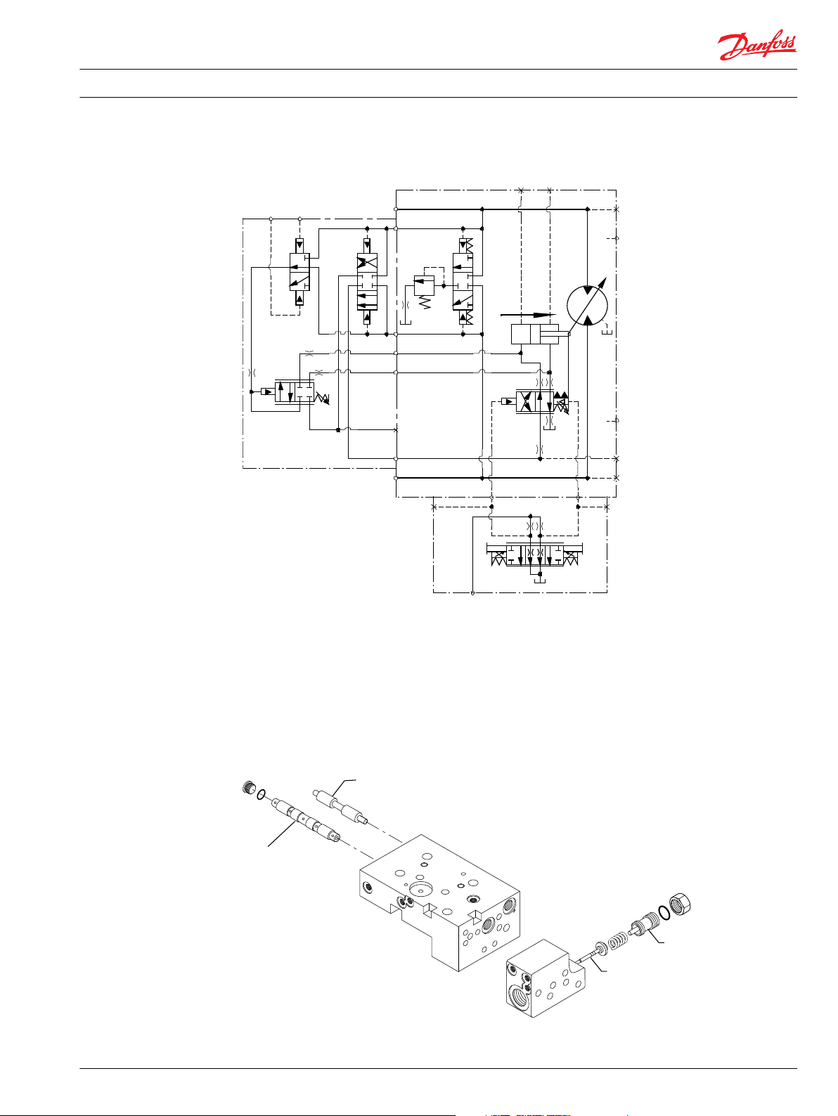
Schematics
E*-A1 Schematic
E*-A2 Schematic
34 11009448 • Rev BA • July 2014
Page 35

M4
M3
M1
L1
L2
M5
M2
M8M7
X1
B
A
Max.
displ.
P101 903
Multifunction Block
Control
Service Manual
EP, EQ, ER, ES Controls
Series 51 Electrohydraulic Proportional Controls Service Manual
E*-A5 Schematic
Repair
Definitions
E*-A1 is the electrohydraulic proportional with PCOR and BPD.
E*-A2 is the electrohydraulic proportional with PCOR.
E*-A5 is the electrohydraulic proportional without PCOR.
* = P, Q, R, or S
Control Housing Disassembly
Do not remove PCP valve (M1) unless replacing it. PCP valve is sold as a complete unit. O-rings are not
available separately.
1. Using a 5/32-inch internal hex wrench, remove screws (M12).
2. Remove the pressure control pilot (PCP) valve (M1) from the control valve housing. (There are no
repairable parts in the PCP.)
3. Using a 1/4-inch in internal hex wrench remove plug (M44), if present.
4. Remove and discard O-ring (M44A).
5. Using a 1/4-inch internal hex wrench remove plugs (M32).
6. Remove and discard O-rings (M32A).
7. Using a 4 mm internal hex wrench remove the screws (M18).
8. Remove valve housing.
9. Remove and discard O-rings (M30, M36, and M38).
10. Remove cover plate (M14). Remove and discard gasket (M16).
11. Remove bias spring (M26). Remove pilot piston (M24).
12. Remove pin (M28).
13. Using a 1/8-inch internal hex wrench remove plug (M42).
14. Remove and discard the O-ring (M42A).
11009448 • Rev BA • July 2014 35
Page 36

P101 945
M32
M28
M24
M26
M1 (PCP)
M42
M44
M32
M16
M14
Service Manual
EP, EQ, ER, ES Controls
Series 51 Electrohydraulic Proportional Controls Service Manual
EP, EQ, ER, ES Control
Legend
Item Wrench size Torque
M18 4 mm internal hex 7 Nm [5 lbf•ft]
M44, M32 1/4 internal hex 30 Nm [22 lbf•ft]
M12 5/32 internal hex 20 Nm [15 lbf•ft]
M44 4 mm internal hex 7 Nm [5 lbf•ft]
PCOR Disassembly
1. Using a 4 mm internal hex, remove screws (N29). Remove the PCOR valve housing (N87).
2. Remove and discard O-rings (N82 and N24P).
3. Using a 1 1/16-inch hex wrench remove locknut (N14).
4. Using a large flat screwdriver or a 13 mm hex wrench remove adjustment assembly (Z).
5. Remove and discard O-ring (N16J). Remove spring (N18). Remove spool assembly (N22 and N20).
6. Using a 1 inch wrench remove plug (N23). Remove and discard O-ring (N23A).
7. Using a 1/8 inch internal hex remove plugs (N27). Remove and discard O-rings (N27A).
8. Using a 3 mm internal hex, remove orifices (U6 and U7).
36 11009448 • Rev BA • July 2014
Page 37

N29
N23
N23A
N22&N20
N18
N27A
N27
N27
N27A
N87
U7
U6
P101 952
Service Manual
EP, EQ, ER, ES Controls
Series 51 Electrohydraulic Proportional Controls Service Manual
PCOR
Legend
Item Wrench size Torque
N27 1/8 inch internal hex 7 Nm [4 lbf•ft]
N23 1 inch 40 Nm [30 lbf•ft]
U6, U7 3 mm internal hex 6 Nm [4 lbf•ft]
N29 5 mm internal hex 16 Nm [12 lbf•ft]
N14 1-5/16 inch N/A
Multifunction Block Disassembly
1. Using a ¼ inch internal hex wrench, remove plugs (N26). Remove and discard O-rings (N26A).
2. Remove the spool (N30).
3. Remove screws (N58). Remove the multifunction block (N1A1).
4. Remove and discard the O-rings (G36, G38, G42) or gasket (N240).
5. Using a 1/8 inch internal hex wrench, remove plugs (N27). Remove and discard O-rings (N27A).
6. If present, remove and discard screens (N52).
7. Using a 3 mm internal hex, remove orifices T4, T5, and T6 , if present.
11009448 • Rev BA • July 2014 37
Page 38

N27
N26
N58
N27
N27
N27A
N27
N30
N26
N27
N52
P101 954
N27
N27
N1A1
T4
T6
T5
G42
G42
G38
G38
G38
G36
N240
C
Service Manual
EP, EQ, ER, ES Controls
Series 51 Electrohydraulic Proportional Controls Service Manual
Multifunction Block
Legend
Item Wrench size Torque
N58
8 mm internal hex 78 Nm [58 lbf•ft]
80cc, 110cc
N58
10 mm internal hex 110 Nm [81 lbf•ft]
160cc, 250cc
Item Wrench size Torque
N27 1/8 inch internal hex 7 Nm [4 lbf•ft]
N26 1/4 inch internal hex 37 Nm [28 lbf•ft]
T4, T5, T6 3 mm internal hex 6 Nm [4 lbf•ft]
Control Orifices
1. Remove plugs (N27) covering orifices (T4, T5, T6) using a 1/8-inch internal hex wrench or a 1/4-inch
wrench.
2. Remove and discard O-rings.
3. Using a 3 mm internal hex wrench, remove all orifices.
4. Clean the orifices thoroughly.
5. Install the orifices. Using a 3 mm internal hex, torque to 4 N•m [3 lbf•ft].
6. Install plugs (N27). Torque plugs to 9 N•m [7 lbf•ft].
Caution
Do not over-torque the orifices.
38 11009448 • Rev BA • July 2014
Page 39

P101 958
(optional)
T3
T1
T7
T8
T2
U5
T4
T5
T6
U7
U6
N27
N27
Service Manual
EP, EQ, ER, ES Controls
Series 51 Electrohydraulic Proportional Controls Service Manual
Control Orifices
Inspection
1. Inspect the multifunction block, shuttle spool, PCOR spool, and PCOR valve housing for damage or
foreign material.
2. Clean all internal passages thoroughly. Replace worn or damaged components as necessary.
Multifunction Block Assembly
1. Lubricate and install new O-rings (N27A).
2. Install plugs (N27). Using a 1/8-inch internal hex wrench torque to 6 N•m [4 lbf•ft].
3. Using petroleum jelly to retain them, install new interface O-rings (G36, G38, and G42), or install
gasket (N240).
4. Position multifunction block on endcap.
5. Install screws (N58). Refer to table for wrench size and torques.
6. Lubricate and install shuttle spool (N30).
7. Lubricate and Install new O-rings (N26A).
8. Install plugs (N26). Using a 1/4-inch internal hex wrench torque to 37 N•m [28 lbf•ft].
11009448 • Rev BA • July 2014 39
Page 40

N58
N26A
N27
P107 830
N240
Service Manual
EP, EQ, ER, ES Controls
Series 51 Electrohydraulic Proportional Controls Service Manual
Install Multifunction Block
Legend
Item Wrench size Torque
N58
80cc, 110cc
N58
160cc, 250cc
8 mm internal hex 78 Nm [58 lbf•ft]
10 mm internal hex 110 Nm [81 lbf•ft]
Item Wrench size Torque
N27 1/8 inch internal hex 7 Nm [4 lbf•ft]
N26 1/4 inch internal hex 37 Nm [28 lbf•ft]
T4, T5, T6 3 mm internal hex 6 Nm [4 lbf•ft]
Inspection
PCOR Assembly
1. Using petroleum jelly to retain them, install new interface O-rings (N24P and N82) to the PCOR valve
housing.
2. Install the PCOR valve housing (N87).
3. Install screws (N29). Using a 5 mm internal hex wrench torque to 9 Nm [7 lbf•ft].
4. Install the PCOR valve spool (N22, and N20) to the cavity in the PCOR valve housing.
5. Install the PCOR spring (N18).
6. Install a new O-ring(N16J). Install the PCOR adjustment screw (Z).
7. Install the PCOR valve locknut (N14). Torque locknut after adjusment.
8. Before returning to normal operation, reset the PC threshold setting. See Adjusting the PCOR Setting
on page 14.
9. Install new O-ring (N23A).
10. Install plug (N23). Using a 1 inch wrench torque to 40 N•m [30 lbf•ft].
11. Lubricate and install O-rings (N27A).
12. Install plugs (N27). Using a 1/8 internal hex, torque to 6 Nm [4 lbf•ft].
40 11009448 • Rev BA • July 2014
Page 41

N23A
N22&N20
N14
N18
Z001
Z002
N87
P101 956
Service Manual
EP, EQ, ER, ES Controls
Series 51 Electrohydraulic Proportional Controls Service Manual
PCOR Valve Assembly
Legend
Item Wrench size Torque
N27 1/8 inch internal hex 7 Nm [4 lbf•ft]
N23 1 inch 40 Nm [30 lbf•ft]
U6, U7 3 mm internal hex 6 Nm [4 lbf•ft]
N29 5 mm internal hex 16 Nm [12 lbf•ft]
N14 1-1/16 inch N/A
Control Housing Assembly
1. Lubricate and install new O-ring (M42A).
2. Install plug (M42). Using a 1/8 internal hex, torque to 6Nm [4 lbf•ft].
3. Install pin (M28). Install pilot piston (M24).
4. Install bias spring (M26). Install gasket (M16).
5. Install cover (M14).
6. Using petroleum jelly to hold them in place, install O-rings (M30, M36, and M38).
7. Install valve housing.
8. Install screws (M18). Using a 4 mm internal hex wrench, torque to 7 Nm [5 lbf•ft].
9. Lubricate and install O-rings (M32A).
10. Install plugs (M32). Using a 1/4 internal hex, torque to 30 Nm [22 lbf•ft].
11. Lubricate and install new O-ring (M44A).
12. If used, install plug (M44). Using a 1/4 intarnal hex, torque to 30 Nm [22 lbf•ft].
13. Using petroleum jelly to hold them in place, install PCP O-rings.
14. Install PCP valve (M1). Install screws (M12).
15. Using a 5/32-inch internal hex, torque to 20 Nm [15 lbf•ft].
11009448 • Rev BA • July 2014 41
Page 42

P101 945
M32
M28
M24
M26
M1 (PCP)
M42
M44
M32
M16
M14
Service Manual Series 51 Electrohydraulic Proportional Controls Service Manual
EP, EQ, ER, ES Controls
EP, EQ, ER, ES Control
Legend
Item Wrench size Torque
M18 4 mm internal hex 7 Nm [5 lbf•ft]
M44, M32 1/4 internal hex 30 Nm [22 lbf•ft]
M12 5/32 internal hex 20 Nm [15 lbf•ft]
M42 4 mm internal hex 7 Nm [5 lbf•ft]
42 11009448 • Rev BA • July 2014
Page 43

Service Manual Series 51 Electrohydraulic Proportional Controls Service Manual
11009448 • Rev BA • July 2014 43
Page 44

Service Manual Series 51 Electrohydraulic Proportional Controls Service Manual
44 11009448 • Rev BA • July 2014
Page 45

Service Manual Series 51 Electrohydraulic Proportional Controls Service Manual
11009448 • Rev BA • July 2014 45
Page 46

Danfoss
Power Solutions GmbH & Co. OHG
Krokamp 35
D-24539 Neumünster, Germany
Phone: +49 4321 871 0
Danfoss
Power Solutions ApS
Nordborgvej 81
DK-6430 Nordborg, Denmark
Phone: +45 7488 2222
Danfoss
Power Solutions US Company
2800 East 13th Street
Ames, IA 50010, USA
Phone: +1 515 239 6000
Danfoss
Power Solutions
(Shanghai) Co., Ltd.
Building #22, No. 1000 Jin Hai Rd
Jin Qiao, Pudong New District
Shanghai, China 201206
Phone: +86 21 3418 5200
Products we offer:
Comatrol
www.comatrol.com
Schwarzmüller-Inverter
www.schwarzmuellerinverter.com
Turolla
www.turollaocg.com
Valmova
www.valmova.com
Hydro-Gear
www.hydro-gear.com
Daikin-Sauer-Danfoss
www.daikin-sauer-danfoss.com
Bent Axis Motors
•
Closed Circuit Axial Piston
•
Pumps and Motors
Displays
•
Electrohydraulic Power
•
Steering
Electrohydraulics
•
Hydraulic Power Steering
•
Integrated Systems
•
Joysticks and Control
•
Handles
Microcontrollers and
•
Software
Open Circuit Axial Piston
•
Pumps
Orbital Motors
•
PLUS+1® GUIDE
•
Proportional Valves
•
Sensors
•
Steering
•
Transit Mixer Drives
•
Danfoss Power Solutions is a global manufacturer and supplier of high-quality hydraulic and
electronic components. We specialize in providing state-of-the-art technology and solutions
that excel in the harsh operating conditions of the mobile off-highway market. Building on
our extensive applications expertise, we work closely with our customers to ensure
exceptional performance for a broad range of off-highway vehicles.
We help OEMs around the world speed up system development, reduce costs and bring
vehicles to market faster.
Danfoss – Your Strongest Partner in Mobile Hydraulics.
Go to www.powersolutions.danfoss.com for further product information.
Wherever off-highway vehicles are at work, so is Danfoss. We offer expert worldwide support
for our customers, ensuring the best possible solutions for outstanding performance. And
with an extensive network of Global Service Partners, we also provide comprehensive global
service for all of our components.
Please contact the Danfoss Power Solution representative nearest you.
Danfoss can accept no responsibility for possible errors in catalogues, brochures and other printed material. Danfoss reserves the right to alter its products without notice. This also applies to
products already on order provided that such alterations can be made without changes being necessary in specifications already agreed..
All trademarks in this material are property of the respective companies. Danfoss and the Danfoss logotype are trademarks of Danfoss A/S. All rights reserved.
11009448 • Rev BA • July 2014 www.danfoss.com
Local address:
©
Danfoss A/S, 2014
 Loading...