

Page 1
IMPORTANT!
DO NOT CROSS OR CUT THE RED CABLE
REMEMBER TO MEASURE, VERIFY AND
RECORD THE RESISTANCE
Danfoss
BRINGING WARMTH TO LIFE
LX
TM
Installation Manual
Electric Heating Mats
Manuel d'installation
Tapis chauffants électriques
Manual de instalación
Mallas calefactoras eléctricas
Page 2

Page 3
Table of Contents
LX Floor Heating System....................................... .......................................................................................................................................... 2
Typical Installations and Cautions ................................................................................................................................................................ 3
General Installation Guidelines ..................................................................................................................................................................... 4
Warranty................................................................................................................................................................................................................. 9
APPENDIX A: Typical Electrical Wiring
Spécifications techniques des tapis chauffants Danfoss LX .................................................................................................................... 10
Installations typiques et mises en garde......................................................................................................................................................... 11
Instructions d'installation d’ordre général ..................................................................................................................................................... 12
.
.......................................................................................................................................................... 26
Garantie ...................................................................................................................................................................................................................... 17
ANNEXE A: Câblage Électrique Typique........................................................................................................................................................... 26
Sistema de calefacción por suelo radiante DanfossLX ............................................................................................ 18
Instalaciones y precauciones típicas. ........................................................................................................................................................... 19
Pautas generales de instalació ....................................................................................................................................................................... 20
Garantía .................................................................................................................................................................................................................. 25
APÉNDICE A: Cableado Eléctrico Típico
....................................................................................................................................................... 26
...............................
Copyright 2009 Danfoss Inc.
088L3380 - 06/09
TEL: 866-676-8062. FAX: 905-285-2055
1
Page 4

Page 5
Danfoss LX Floor Heating System
CAUTION!
It is important that this equipment is installed only by qualified electricians who are familiar with the proper sizing,
installation, construction and operation of floor warming system and the hazards involved. The heating mat is designed for
under floor heating purposes only.
Note!
The installation shall be in accordance with the manufacturer’s instructions and national and local codes.
The installation shall be in accordance with Part 424-J, American National Standard Institute / National Fire
Protection Association (ANSI/NFPA70), National Electrical Code (NEC) and Canadian Electrical Code (CEC),
Part 1. Danfoss recommends GFCI for heating cable in normally wet areas (i.e. bathrooms, showers, kitchens).
LX Mat Specifications
Type:
Voltage:
Output:
Heating Element Size:
Twin conductor
120V, 240V
12W/sq.ft. (130 W/m )
Width: 2’
2
Length: Refer to product label
Height: approx 1/8” (4 mm)
Cold Lead
Bending radius:
Wire insulation:
Casing:
Max. Allowable Temp.:
Min. Installation Temp.:
Note: Operating the 240V mat at 208V reduces power output to approximately 9W/sq.ft.
(25% reduction)
10’ (3.0 m)
Minimum 3/4” (19 mm)
FEP, Teflon
TM
PVDF
212°F (100°C)
40°F (5°C)
WARNING:
Remember to measure resistance.
Little Buzzer
Connection 120V
Phase - Black
Neutral - Blue
Ground - Shield
Connection 240V
Phase - Black
Phase - Blue
Ground - Shield
MONITOR YOUR INSTALLATION!
USE THE LITTLE BUZZER CONTINUITY
ALARM (PART#088L0028)
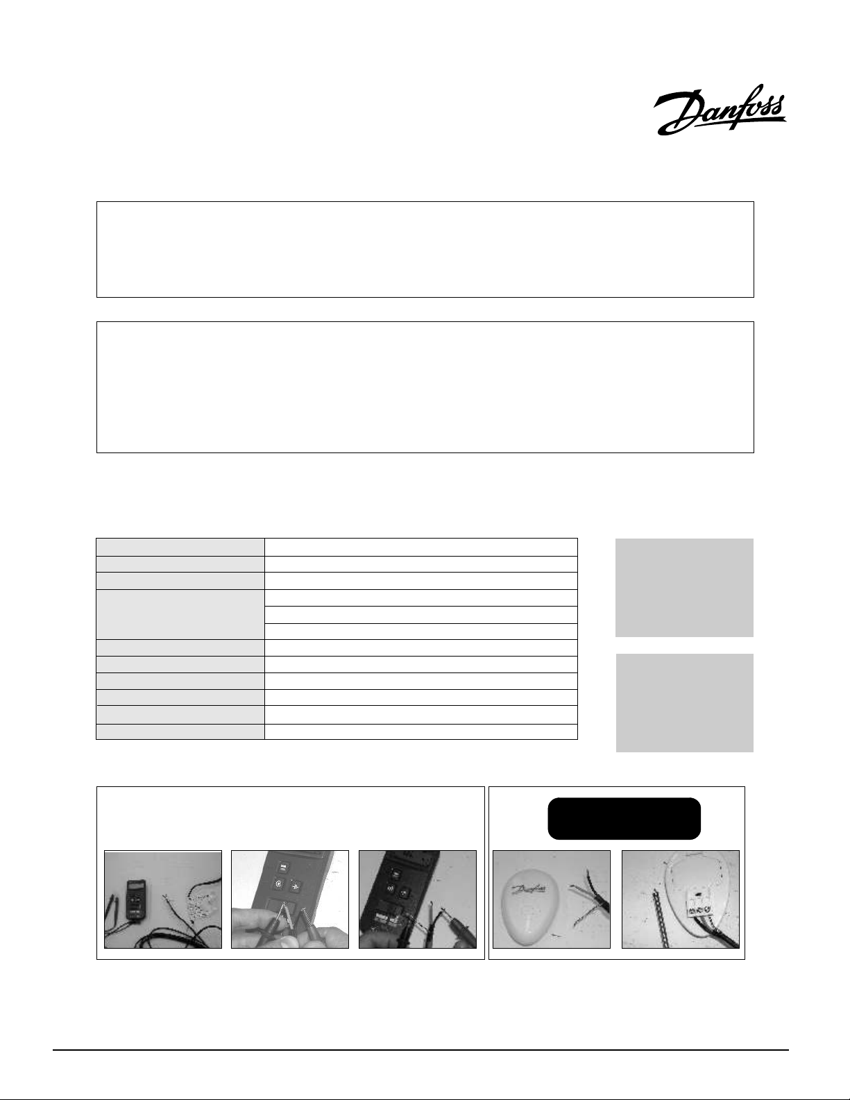
The resistance should be measured between the two conductors, blue and black. Compare the measured resistance to the resistance listed on
the product label (on the power lead).
Record the resistance on your warranty card.
infinity.
Copyright 2009 Danfoss Inc.
Also, measure the resistance between the blue, black and shielding/ground wire. Both should read
088L3380 - 06/09
TEL: 866-676-8062. FAX: 905-285-2055
2
Page 6
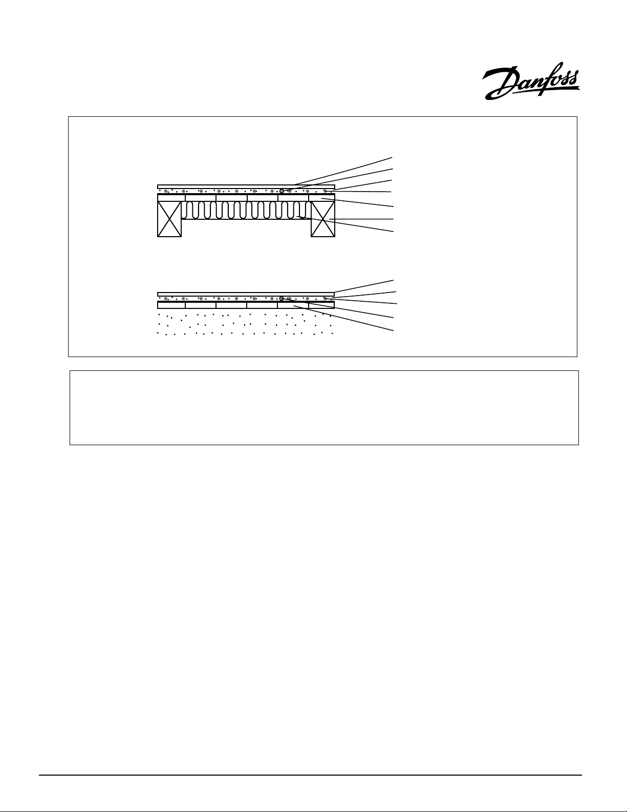
Danfoss LX typical installations and applications
Directly on plywood:
Directly on concrete.
Alternative method: self-leveling cement is
recommended for large surfaces and the
following floor materials: engineered wood,
laminate, floating floors, vinyl, linoleum and
carpet.
Ceramic tiles
Thermostat sensor
Thinset cement adhesive
fanD oss LX
Plywood on joists
Joists
Insulation (optional)
Ceramic tiles
Thin set cement adhesive
Danfoss LX
Thermosta
Concrete
t sensor
Warning:
Consult the manufacturer for information on special
installation requirements for wood, laminate and
vinyl or linoleum flooring.
Caution!
=Read the instructions carefully before installing
LX mat
=Do not install LX mat in walls or ceilings;
=The mat must be embedded in mortar,
thinset, concrete or similar material;
=The minimum installation temperature is
40°F (5°C);
=Never cut the red heating wire;
=It is recommended to use AWG 16 or greater
copper wire only if you need to extend the cold
lead
=Never install the LX mat such that two red
heating wires touch, cross or overlap;
=Measure the resistance between the blue,
black and shielding/ground wire. Both should
read infinity.
lRe memb er to al ways me asur e, ver ify and
record the actual resistance throughout the
install ation process (out of the box, af ter
installation, before thin set cement or self-leveler
application and after installation of floor tiles) and
compare all reading to the ratings on the product
label.
lRemember to check that the supply voltage
matches the voltage of the Danfoss LX mat;
lRemember to place the labels as written in
this instruction;
lOnly for indoor installation;
lMetal struct u res or materials used for the
support of or on which the Danfoss LX mat is
insta lled m ust be gro u nded in a ccorda n ce
with CSA Standard C22.1, section 10 and the NEC.
Please consult the factory for any other
questions or advice;
Copyright 2009 Danfoss Inc.
088L3380 - 06/09
TEL: 866-676-8062. FAX: 905-285-2055
3
Page 7
General Installation Guidelines
1
2
Step 1. PLAN LAYOUT
Make a sketch layout or a floor plan of the room;
include all permanent furnishings such as toilets,
bathtubs, appliances, cabinetry, etc. Indicate all
dimensions required to determine the available floor
are a and the position of th e LX thermo s t at.
TIP: Danfoss recommends installation is documented
with photos to note the location of connections and
the sensor.
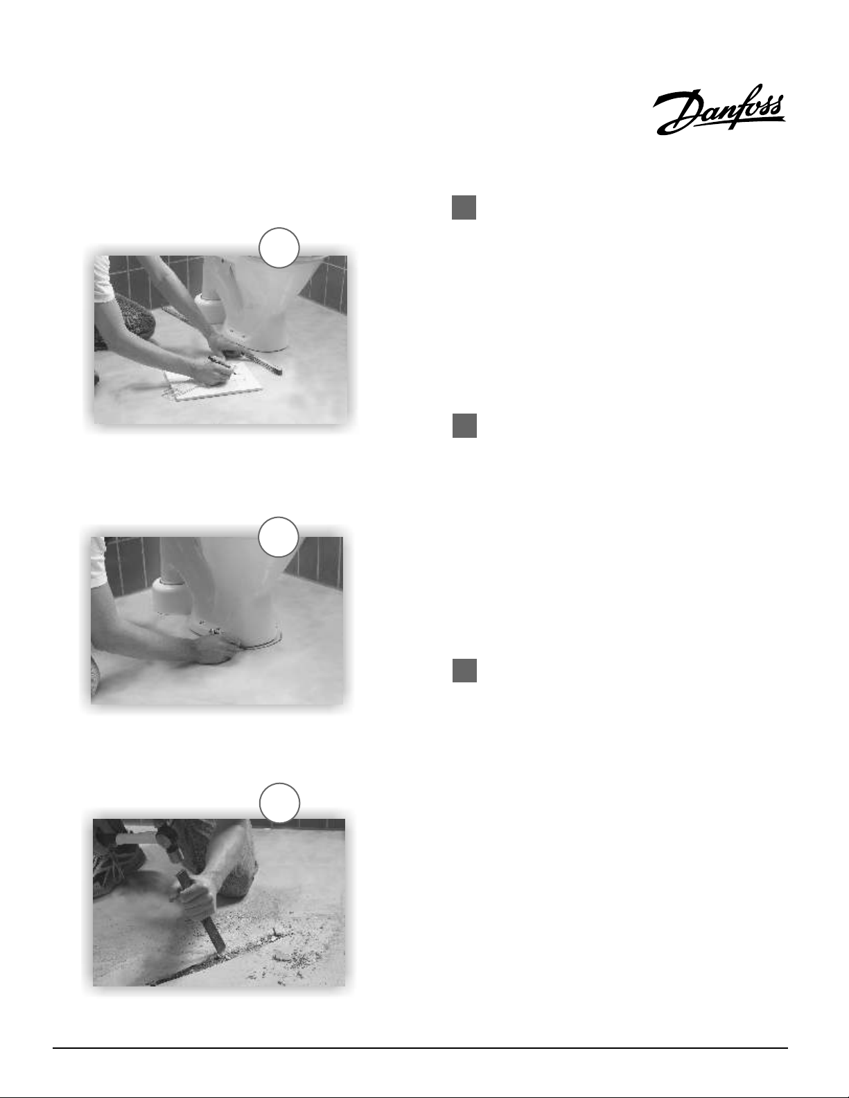
Step 2. TRANSFER LAYOUT TO FLOOR
Draw an outline of the layout on the room floor including
a foot print of all furnishings that are not yet
installed. Unroll the first few feet of the LX mat. The
starting point of the cable must be placed within 10 ft.
from the thermostat. Mark the position of the connection
point between the power lead and the red LX heating
cable. This connection must be concealed in thinset or
self-leveling cement. When using a floor temperature
sensing thermostat, mark the sensor position in the
middle of 2 heating cables, about 10 in. (25cm) away from
the wall (within the heated area), as close as possible to
the thermostat.
Copyright 2009 Danfoss Inc.
3A
088L3380 - 06/09
Step 3. INSTALL SENSOR
(recommended in conduit, part#19809099 included)
If using a floor temperature sensing thermostat, install
the sensor now, either in conduit tube, or directly to
the subfloor. It is recommended that the sensor be
installed in conduit tube. This will allow the sensor
to be easily replaced in the unlikely event of failure.
The sensor and/or tube needs to be installed between
the thermostat wall box and the sensor position.
The conduit tube must be partially countersunk into the
subfloor. Cut a channel 5/16” deep by 5/16” wide in the
floor and wall up to the thermostat large enough to
accommodate the sensor conduit. The conduit has to go
from the thermostat and minimum of 10 “ away from the
wall towards the middle of the floor.
TEL: 866-676-8062. FAX: 905-285-2055
4
Page 8
4
IMPORTANT: the sensor conduit must be centered in
the cable loop (between two red heating wires).
Seal the end of the conduit that is placed in the floor with a
piece of duct tape. This will prevent thinset from penetrating
the conduit.
Use duct tape to hold the sensor conduit into the groove to
prevent it from floating up when the mortar or thinset is
poured.
If the sensor is installed directly in the mortar bed, use duct
tape to secure to subfloor.
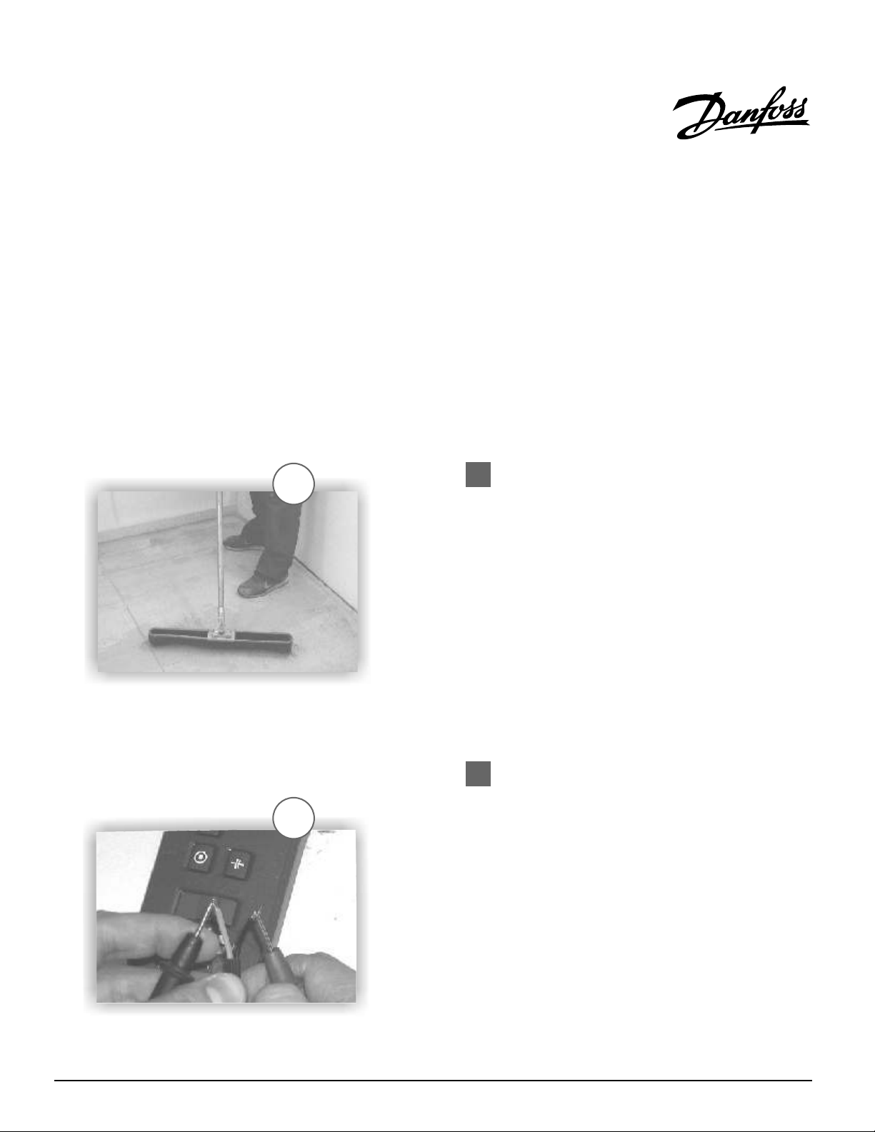
Step 4. PREPARE SUBFLOOR SURFACE
Clean and vacuum the floor thoroughly and remove dust
and debris from the floor that may damage the heating
cable or reduce adhesion.
Ensure that the subfloor is secure and stable. Carefully fill
in all cracks to prevent any potential damage to the new
tiles resulting from shifts in the subfloor.
5A
(Optional) To ensure maximum adhesion, apply a primer
or sealer as recommended by the thinset or self-leveling
cement manufacturer. If using a primer, ensure that the
entire floor is covered. Allow the primer to dry thoroughly
before proceeding to the next steps.
Step 5A. MEASURE THE RESISTANCE
Use a digital ohm meter to measure the resistance of
the Danfoss LX mat and compare it to the resistance listed
on the product label. The resistance should be measured
between the two conductors, blue and black. Compare
the measured resistance to the resistance on the product
label, located 3 inches from the splice, on the cold lead.
Also, measure the resistance between the blue, black and
shielding/ground wire. Both should read infinity.
Record the measured resistance on the warranty
card. Documenting the resistance at each stage of
in stallatio n is req uired for warra nty purpose s.
Copyright 2009 Danfoss Inc.
088L3380 - 06/09
TEL: 866-676-8062. FAX: 905-285-2055
5
Page 9
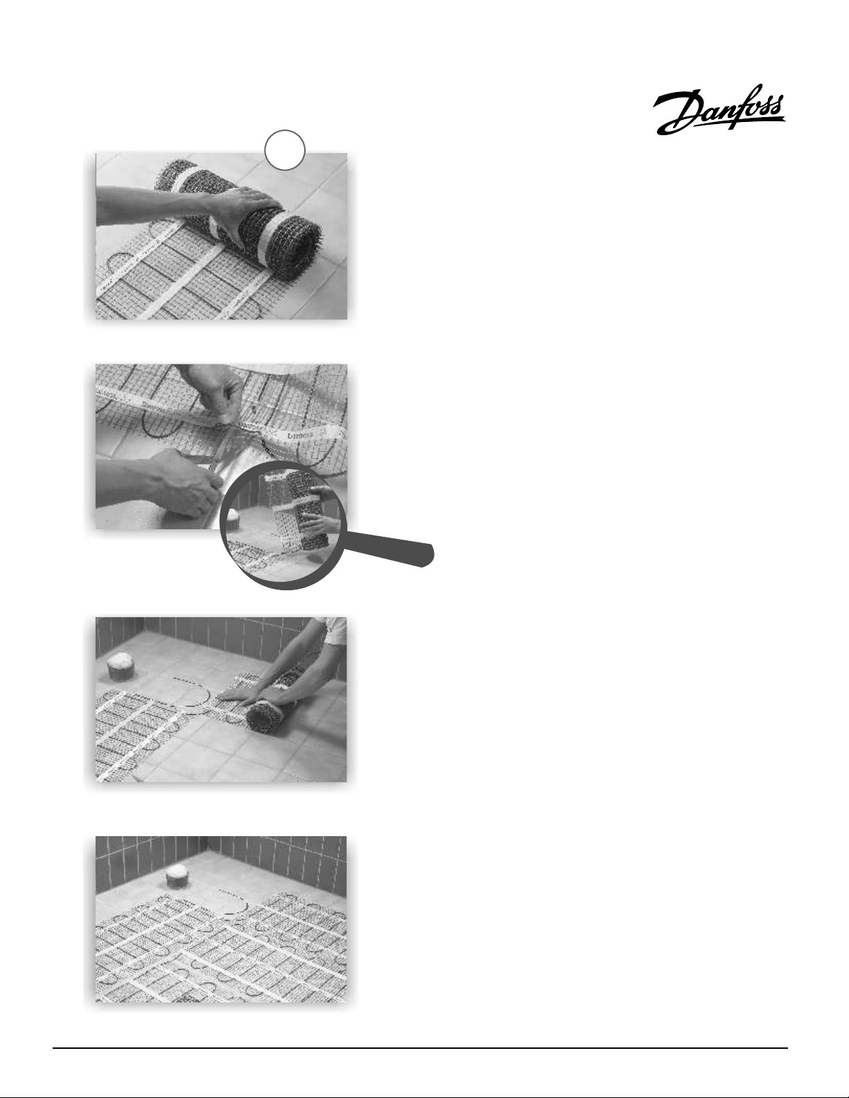
5B
Step 5B. INSTALL THE LX MAT
An adhesive has been added to the bottom of the mat
which will prevent the mat from moving during
installation. Start by placing the mat such that the
connection point and the temperature sensor are in their
intended positions and bring the power cable to the
thermostat or connection box.
Begin unrolling the LX mat evenly across the floor
outside the areas that you marked previously.
The adhesive on the mat is made such that the mat may
be mo ved s ever al t i mes b e fore i t l ose s i ts
adhesiveness. When you reach the next wall, cut
the grey mesh, turn the mat, and begin rolling
in the desired direction.
NEVER CUT OR SHORTEN THE RED HEATING CABLE!
Ensure that the LX mat is in full contact with the
subfloor at all times. Avoid walking on the heating
mat. If this is not possible, use shoes with soft soles.
When approaching obstacles (toilets, cabinets, etc.),
carefully remove some of the red heating cable
f r o m t h e m a t a n d l e a d t h e c a b l e
around the obstacle. In some cases pieces of the
grey mesh will be cut away entirely. Remember to never
cut the red cable. Use hot melt glue or a thin strip of tape
to secure the loose cable to the floor.
Copyright 2009 Danfoss Inc.
088L3380 - 06/09
TEL: 866-676-8062. FAX: 905-285-2055
6
Page 10
6
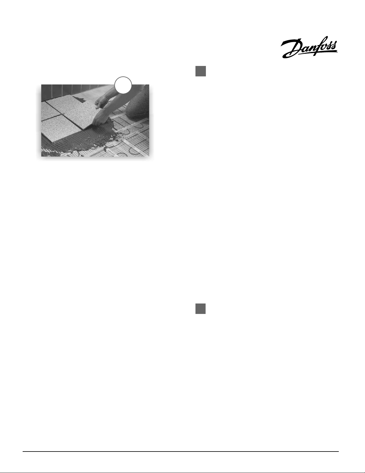
Step 6. INSTALL FLOOR COVERING
Measure the resistance in the mat and record it on the
warranty certificate. It is highly recommend to take
photographs of the installed LX mat before installing
the flooring.
ENSURE THAT THE SENSOR CONDUIT HAS BEEN
PROPERLY INSTALLED BEFORE PROCEEDING (see Step 3).
In the case of tiles, proceed with the installation of the tiles
by covering the heating cables with a layer of thin-set
cement as directed by the tile manufacturer. Ensure that the
thin-set mortar covers the entire height of the heating
cable as the tiles are installed. In the case of a wood,
engineered or laminate floor covering, it is recommended
that the flooring manufacturer be contacted. For wooden
floors, a minimum of 3/16 in. of self-leveling cement over
the heating cable is recommended. Ensure that all
moisture in the self-leveling cement has been fully
eliminated in accordance with the drying times
recommended by the manufacturer (consult the
manufacturer for exact drying time).
Once the thin-set cement has dried, measure the
resistance in the mat and record it on the warranty
certificate. The LX mat must not be turned on until the thin-
set cement has fully dried. A minimum of seven (7) days is
recommended.
Copyright 2009 Danfoss Inc.
088L3380 - 06/09
Step 7. CONNECT POWER SUPPLY AND
THERMOSTAT
(See Appendix A)
The connection of the power supply and the LXstat GFCI
thermostat must be done by a qualified electrician in
accordance with the National Electrical Code (NEC) and
the Canadian Electrical Code (CEC). The electrician
should also feed the sensor cable into the installed conduit
and connect it to the thermostat.
TEL: 866-676-8062. FAX: 905-285-2055
7
Page 11

8
Step 8. RECORD INFORMATION AND AFFIX
LABELS
A final resistance reading must be taken and recorded on the
warranty certificate. Compare the resistance values with values
listed on the cold lead. Also, measure the resistance between the
blue, black and shielding/ground wire. Both should read infinity. It
is important for the homeowner to mail in the certificate
immediately after installing the LX mat and thermostat.
Failure to do so could void the manufacturer's warranty. The
warranty is subject to the guarantee conditions listed on the
warranty certificate.
Label 1: Product identification label
The eight digit product code provided on the LX mat label must be
recorded on the warranty certificate.
Label 2: Electric panel label
This label is to be placed inside the electric panel. On this label
record the name of the room where the heating cable has been
installed.
Label 3: The warning label
The warning label must be placed in the room where the
heating cable has been installed, preferably on the floor.
The label should be kept in the room at least for the
duration of the construction or renovation of the floor.
Copyright 2009 Danfoss Inc.
9
088L3380 - 06/09
Step 9. ENJOY THE COMFORT OF DANFOSS LX
The LX floor heating system is now ready to use. Increase the
floor temperature gradually and adjust it until it reaches a
comfortable level depending on the type of room and your
personal preferences.
TEL: 866-676-8062. FAX: 905-285-2055
8
Page 12

EXTENDED WARRANTY
For a period of ten (10) years from the date of purchase Danfoss warrants that the Danfoss LX mat is free from
defects in material, design and workmanship. The extended warranty is only valid if the warranty certificate has
been properly completed and mailed, and the installation is in accordance with the installation instructions.
The defective Danfoss LX cable has to be inspected by or submitted to Danfoss or an authorized Danfoss LX dealer.
Failure to comply with all of the foregoing will void this extended warranty. Danfoss will, when the customer has
documented that a defect in the Danfoss LX was present at the date of delivery, repair or supply a new Danfoss LX
at Danfoss’ option. All claims shall be made within the extended warranty period. Danfoss shall not be liable for any
claims made later than ten years from date of purchase.
Danfoss shall not be liable for any consequential and secondary costs or damages linked to the defect or
replacement of the Danfoss LX. Danfoss will be liable for any costs related to the dismantling of defective product
and the installation of a new product; however such liability is limited to the amount of five (5) times the initial
product costs for each damage/case.
THE FOREGOING WARRANTY IS EXPRESSLY IN LIEU OF ALL OTHER WARRANTIES, EXPRESS OR IMPLIED, ON THE PART OF
DANFOSS. DANFOSS DISCLAIMS ANY WARRANTY, EXPRESS OR IMPLIED, OF MERCHANTABILITY OR FITNESS FOR A
PARTICULAR PURPOSE. DANFOSS NEITHER ASSUMES NOR AUTHORIZES ANY OTHER PERSON, FIRM OR CORPORATION TO
ASSUME FOR IT ANY OTHER LIABILITY IN CONNECTION WITH SALE OR PRODUCT. DANFOSS SHALL NOT BE HELD
RESPONSIBLE FOR DAMAGE TO PERSON OR PROPERTY, CONSEQUENTIAL LOSS, LOSS OF PROFIT, LOSSES ON GOODS IN
STORE, OR THE LIKE WHICH MIGHT ARISE OUT OF THE FAILURE OF THE EQUIPMENT DELIVERED, IRRESPECTIVE OF THE CAUSE
(INCLUDING FAULTY MANUFACTURE).
How to claim this warranty
Contact the company's Customer Service
depar t ment and provide t h e following
information:
1) Nature of the manufacturing defect
2) Date of purchase and, if already
installed, date of installation
3) If installed, name of electrician and
flooring installer
4) Resistance readings taken by installer
5) Proof of purchase and serial number
from product label
Our Customer Service department will provide
you with an authorization number and advise you
on the next steps to complete your warranty
claim.
Copyright 2009 Danfoss Inc.
088L3380 - 06/09
Disclaimer:
This warranty gives you specific legal rights and you may
also have some legal rights which may vary from state to
state or province to province. Danfoss hereby disclaims,
and it is as a condition of the sale, that there are no implied
warranties. Some states and provinces do not allow
limitations on an implied warranty so the above limitation
may not apply to you.
Manufacturer:
Mail: Danfoss Inc.
6711 Mississauga Rd.,
Suite 410
Toronto, ON
L5N 2W3
Phone: 905-285-2050
1-866-676-8062
Fax: 905-285-2055
TEL: 866-676-8062. FAX: 905-285-2055
9
Page 13

Dispositif de chauffage de plancher DanfossLX
ATTENTION!
Il est important que ce tapis chauffant soit installé uniquement par un électricien agréé qui connaît le calibrage, le mode
d'installation, la construction et le fonctionnement des systèmes de chauffage de plancher ainsi que les risques associés.
Le tapis chauffant a été conçu à des fins de chauffage seulement par-dessous le plancher.
REMARQUE
L'installation doit se faire conformément aux instructions du fabricant et aux codes nationaux et locaux. Elle doit respecter
la section 424-J, American National Standards Institute / National Fire Protection Association (ANSI / NFPA70), le National
Electrical Code et la Première partie du Code canadien de l'électricité. Vous devez vous servir d'un dispositif de protection
contre les défauts de terre ou d'un dispositif de courant résiduel dans les salles de bains et autres pièces.
Spécifications techniques des tapis chauffant Danfoss LX
Type:
Tension:
Puissance:
Dimension de l’élément
chauffant:
Liaison froide:
Rayon de pliage
Isolation de fil
Enveloppe:
Température admissible max.:
Temp. min. d’installation:
:
:
Faisceau double
120V, 240V
pied carré
12W/ (130 W/m )
Largeur
: 2’
Longueur : Référez-vous à l'étiquette du produit
taille
: approx 1/8” (4 mm)
10’ (3.0 m)
Mín.
3/4” (19 mm)
FEP, Teflon
PVC
212°F (100°C)
40°F (5°C)
MC
2
Note: Si le tapis chauffant de 240V est alimenté par une tension de 208V, la puissance émise par le
tapis est de 9W/pied carré (une réduction d’environ 25%).
AVERTISSEMENT :
Pensez à mesurer la résistance
Little Buzzer
SURVEILLER L’INSTALLATION GRÂCE
AU PETIT AVERTISSEUR SONORE DE
CONTINUITÉ ( # 088L0028).
Connexion 120 V
Phase Noir
Neutre Bleu
Terre Blindage
Connexion 0 V
24
Phase Noir
Phase Bleu
Terre Blindage
La résistance doit être mesurée entre les deux conducteurs, le bleu et le noir. Comparer la résistance mesurée à
celle mentionnée sur l'étiquette du produit (sur le fil d'alimentation). Noter la résistance sur la fiche de garantie.
Les résistances entre la terre (nu) et les conducteurs bleu et noir devraient aussi être mesurées, et devraient être
infinies.
Copyright 2009 Danfoss Inc.
088L3380 - 06/09
TEL: 866-676-8062. FAX: 905-285-2055
10
Page 14

Installations et applications typiques de Danfoss LX
Directement sur du contreplaqué
Directement sur du b toné
Autre façon : il est recommandé d'utiliser du
ciment autonivelant pour les grandes surfaces
ainsi que pour les matériaux de recouvrement
suivants : bois d'ingénierie, parquet lamellaire,
parquet flottant, vinyle, linoléum et tapis.
Tuiles de céramique
Sonde de thermostat
Mortier ciment-colle
fanD oss LX
Contreplaqu sur poutrelles é
Poutrelles
Isolation (facultatif)
Tuiles de céramique
Mortier ciment-colle
Danfoss LX
Sonde de thermostat
B toné
Mise en garde
Pour obtenir de l'information sur les exigences d'installation
particulières des revêtements en bois, en parquet lamellaire,
en vinyle ou en linoléum, consulter le fabricant.
ŸAttention!
Ÿ Avant d'installer LXmat, lisez avec soin les
instructions d'installation.
Ÿ
Ÿ N'installez pas LXmat dans le mur ou le plafond.
Ÿ Le tapis doit être encastré dans du mortier, un
mélange de mortier, du béton ou autre matériau
semblable.
Ÿ La température minimale d'installation est de 5 °C
(40 °F).
Ÿ Ne coupez pas le fil de chauffage rouge.
Ÿ Il est recommandé d'utiliser uniquement du fil de
cuivre.
Ÿ N'installez pas LXmat de façon à ce que les deux
fils de chauffage rouges se touchent, se croisent
ou se chevauchent.
Ÿ N'oubliez pas de continuellement mesurer, vérifier
et inscrire la résistance tout au long du processus
d'installation (au moment de l'ouverture de la boîte,
après l'installation, avant la pose de ciment à pose
simplifiée ou du produit autonivelant, et après
l'installation de tuiles), et comparez toutes les
résistances mesurées à celles indiquées sur
l ’ é t i q u e t t e d e l a l i a i s o n f r o i d e .
Ÿ N'oubliez pas de vérifier si la tension d'alimentation
correspond à la tension du tapis Danfoss LX.
Ÿ N'oubliez pas d'apposer les étiquettes tel qu’indiqué
dans les instructions.
Ÿ Po ur u ti li sa t io n à l 'i nt ér ie ur s eu le m en t.
Po u r toute autre question ou tout co n s eil,
communiquez avec l'usine. Les structures métalliques
ou matériaux servant au soutien ou à l'installation de
LXmat Danfoss doi ve n t être mis à l a te r re
conformément à la norme C22.1, article 10, de la CSA, et
conformément au National Electrical Code.
Copyright 2009 Danfoss Inc.
088L3380 - 06/09
TEL: 866-676-8062. FAX: 905-285-2055
11
Page 15

Instructions d'installation d'ordre général
1
Étape 1. SCHÉMA D’INSTALLATION
Tracez un plan ou un croquis de la pièce, en y incluant tout
accessoire permanent comme la toilette, la baignoire, les
appareils ménagers, les armoires, etc. Indiquez toutes les
dimensions afin d'établir la superficie de plancher
disponible et l'emplacement du thermostat LX.
CO NSEIL : Da nfoss conseille de documenter
l'installation avec des ph otos afin de noter
l'emplacement des branchements et de la sonde.
2
Étape 2. TRANSFERT DU PLAN AU PLANCHER
3A
Dessinez le plan sur le faux plancher de la pièce. Dessinez la
place occupée par tous les meubles qui y seront installés.
Déroulez les quelques premiers pieds de tapis Danfoss LX.
Marquez l'emplacement de la connexion entre le câble
d'alimentation (liaison froide) et le câble de chauffage rouge.
Cette connexion doit se trouver à l'intérieur du ciment à
pose simplifiée ou du ciment autonivelant. Si vous avez une
sonde de température au plancher (p. ex., LXstat 430), marquez
l'emplacement de la sonde. Elle devrait se trouver au milieu de
deux câbles de chauffage et à environ 25 cm (10 po) à l'intérieur
du tapis, aussi près que possible du thermostat.
Étape 3. POSE DU CONDUIT ET DE LA SONDE
conduit recommandé , # de pièce 19809099 - inclus
( )
Il faut installer le conduit flexible pour la sonde entre la boîte
électrique du thermostat et la sonde, au cas où il serait
nécessaire de changer la sonde. Ce conduit doit être fraisé dans
le faux plancher.
Taillez un canal d'environ 5/16 po de profond et 5/16 po de
large dans le plancher et dans le mur jusqu'au thermostat, en
vue d'y insérer le conduit du capteur. Ce conduit doit aller du
thermostat vers le milieu du plancher, se terminant à au moins
10 po du mur.
Copyright 2009 Danfoss Inc.
088L3380 - 06/09
TEL: 866-676-8062. FAX: 905-285-2055
12
Page 16

4
IMPORTANT : le conduit de sonde doit être centré dans la
boucle de câble (entre deux fils chauffants rouges).
Utiliser du ruban adhésif en toile pour fermer l'extrémité du
conduit et ainsi empêcher toute introduction de mortier
ciment-colle dans le conduit.
Utiliser ce même adhésif pour fixer le conduit de sonde dans
la rigole et l'empêcher de flotter lors de l'application du
mortier ou du mortier ciment-colle.
Si la sonde est posée directement dans le bain de mortier,
utiliser du ruban adhésif en toile pour la fixer au sousplancher.
Étape 4. PRÉPARATION DE LA SURFACE DU
FAUX PLANCHER
Assurez-vous que le faux plancher est solidement fixé et
qu'il ne bougera pas. Remplissez les fissures afin de
prévenir tout dommage ultérieur aux tuiles en raison d'un
déplacement du plancher.
5A
Nettoyez le faux plancher, passez soigneusement
l'aspirateur pour enlevez toute poussière et tous les débris
qui pourraient endommager le câble de chauffage ou
réduire l'adhésion.
(En option) Afin d'assurer une adhésion maximale,
ap pli quez un apprê t ou un sce llan t selon les
recommandations du fabricant du ciment (pose simplifiée
ou autonivelant). Si vous utilisez un apprêt, assurez-vous
de couvrir tout le plancher. Laissez l'apprêt sécher
complètement avant de passer aux étapes suivantes.
Étape 5 : MESURE DE LA RÉSISTANCE
À l'aide d'un ohmmètre numérique, mesurer la résistance
du câble LX et la comparer à celle mentionnée sur
l'étiquette du produit. Noter la résistance mesurée sur la
fiche de garantie. Les informations relatives à la résistance
à chaque phase de l'installation sont nécessaires à des fins
de garantie.
Les résistances entre la terre (nu) et les conducteurs bleu
et noir devraient aussi être mesurées, et devraient être
infinies.
Copyright 2009 Danfoss Inc.
088L3380 - 06/09
TEL: 866-676-8062. FAX: 905-285-2055
13
Page 17

5B
Étape 5B. INSTALLATION DE LX MAT
Le dessous du tapis est adhésif afin de l'empêcher de
bouger pendant l'installation. Commencez en plaçant le
tapis de façon à ce que le point de connexion et la sonde de
température se trouvent au bon endroit et amenez le câble
d'alimentation vers le thermostat ou la boîte de
connexion.
Commencez à dérouler tapis Danfoss LX uniformément
sur le plancher, en dépassant les démarcations déjà
tracées. L'adhésif du tapis est conçu de façon à permettre
de déplacer le tapis plusieurs fois avant qu'il perde de son
efficacité. Lorsque vous arrivez au mur opposé, coupez la
maille grise, tournez le tapis et commencez à le dérouler
dans le sens contraire.
NE JAMAIS COUPEZ NI RACCOURCIR LE CÂBLE DE
CHAUFFAGE ROUGE!
Assurez-vous que LX mat est toujours en plein contact
avec le faux plancher. Évitez de marcher sur le tapis
chauffant. Si cela n'est pas possible, portez des chaussures
à semelle souple.
Lorsque vous approchez d'obstacles (toilette, armoire,
etc.), enlevez soigneusement une partie du câble de
chauffage rouge de la maille grise et acheminez le câble
autour de l'obstacle. Dans certains cas, le maille grise sera
complètement enlevée. N'oubliez pas : le câble rouge ne
doit jamais être coupé. Fixez le câble libre au plancher au
moyen de colle thermofusible ou d'un mince ruban
adhésif.
Copyright 2009 Danfoss Inc.
088L3380 - 06/09
TEL: 866-676-8062. FAX: 905-285-2055
14
Page 18

6
Étape 6. INSTALLATION DU RECOUVREMENT
DE PLANCHER
Mesurez la résistance du tapis et inscrivez-la dans le tableau
figurant sur le certificat de garantie. Il est fortement
recommandé de prendre des photos de LXmat, une fois
celui-ci installé, avant de poser le recouvrement.
AVANT DE CONTINUER, ASSUREZ-VOUS QUE LE CONDUIT DE
LA SONDE EST BIEN INSTALLÉ (Voir l'étape 3).
Si vous posez des tuiles, couvrez les câbles de chauffage d'une
couche de ciment à pose simplifiée en suivant les directives
du fabricant des tuiles. Assurez-vous que le mortier à pose
simplifiée couvre toute la hauteur du câble de chauffage lors
de la pose des tuiles.
Si vous posez un plancher de bois, de bois d'ingénierie ou du
parquet lamellaire, il est recommandé de communiquer avec
le fabricant du recouvrement.
Pour les planchers de bois, il est recommandé de poser au
moins 3/16 po de ciment autonivelant sur le câble chauffant.
Assurez-vous que toute humidité que renferme le ciment
autonivelant s'est bien évaporée, conformément aux durées
de séchage recommandées par le fabricant (pour obtenir la
durée exacte du séchage, communiquez avec le fabricant).
Une fois que le ciment à pose simplifiée a séché, mesurez la
résistance du tapis et inscrivez-la sur le certificat de garantie.
LXmat ne doit pas être allumé avant le séchage complet du
ciment à pose simplifiée. On recommande une durée de
séchage d'au moins sept (7) jours.
Étape 7 . CONNEXION DE L'ALIMENTATION EN
COURANT ET DU THERMOSTAT
(Voir l’Annexe A)
La connexion de l'alimentation et du thermostat LXstat GFCI
doit être effectuée par un électricien agréé, conformément au
National Electrical Code et au Code canadien de l'électricité.
L'électricien doit aussi amener le câble de la sonde dans le
conduit et la connecter au thermostat.
Copyright 2009 Danfoss Inc.
088L3380 - 06/09
TEL: 866-676-8062. FAX: 905-285-2055
15
Page 19

8
Étape 8 . CONSIGNATION D'INFORMATION ET
APPOSITION DES ÉTIQUETTES
Prendre un relevé de la résistance et inscrire cette valeur sur le
certificat de garantie. Il est important que le propriétaire
conserve cette page en lieu sûr aux fins de consultation.
L'électricien doit également remplir le certificat, sinon la
garantie du fabricant pourrait être annulée. La garantie est
assujettie à toutes les conditions indiquées sur le certificat.
Étiquette 1: Identification du produit :
Le code du produit comportant huit chiffres et figurant
sur l'étiquette de LXmat doit être inscrit sur le certificat
de garantie.
Étiquette 2: Pour le panneau électrique:
Cette étiquette doit être apposée sur le panneau
électrique. Y inscrire le nom de la pièce où l'on a installé
le câble de chauffage.
Étiquette 3: Mise en garde:
L'étiquette de mise en garde doit être placée dans la
pièce où l'on a installé le câble de chauffage, de
préférence sur le plancher. Cette étiquette doit rester
dans la pièce pendant toute la durée de la construction
9
Étape 9. APPRÉCIEZ LE CONFORT DU TAPIS LX DE
DANFOSS
Vous pouvez maintenant utiliser le système de chauffage
de plancher LX. Augmentez la température graduellement
jusqu'à ce que vous atteigniez un niveau confortable selon
le type de pièce et vos préférences.
Copyright 2009 Danfoss Inc.
088L3380 - 06/09
TEL: 866-676-8062. FAX: 905-285-2055
16
Page 20

PROLONGATION DE GARANTIE
Pendant une période équivalant dix (10) ans à compter de la date d'achat, Danfoss garantit que le câble Danfoss LX
est exempt de défauts de matériau, conception et main d'œuvre. La prolongation de garantie est valable
uniquement si le certificat de garantie a été correctement rempli et envoyé, et si l'installation est conforme aux
instructions.
Le câble Danfoss LX défectueux doit être examiné par Danfoss ou soumis à l'expertise de ses services ou d'un
revendeur agréé de Danfoss LX. Le non-respect des instructions précédentes annulera la prolongation de
garantie. Danfoss, une fois que le client aura documenté la présence d'un défaut dans le câble Danfoss LX à la date
de livraison, s'engagera à son entière discrétion à réparer ou à fournir un câble Danfoss LX neuf. Toutes les
réclamations doivent être portées à la connaissance de Danfoss pendant la période de garantie. Danfoss ne pourra
être tenu responsable de toutes les réclamations postérieures aux dix années écoulées à compter de la date
d'achat.
Danfoss ne pourra être tenu responsable de tout dommage indirect et de tout frais ou dommage secondaire liés
au défaut ou au remplacement du tapis chauffant Danfoss LX. Danfoss sera responsable de tout frais associé au
démontage du produit défectueux et à l'installation d'un nouveau produit ; toutefois, cette responsabilité est
limitée à cinq (5) fois le montant des coûts initiaux du produit pour chaque dommage/cas.
LA GARANTIE SUSMENTIONNÉE REMPLACE EXPRESSÉMENT TOUTES LES AUTRES GARANTIES, EXPRESSES OU IMPLICITES, DE
DANFOSS. DANFOSS DÉCLINE TOUTE RESPONSABILITÉ QUANT À UNE GARANTIE EXPRESSE OU IMPLICITE, DE
COMMERCIALISATION OU D'ADÉQUATION À DES FINS SPÉCIFIQUES. DANFOSS DÉCLINE TOUTE RESPONSABILITÉ LIÉE À LA
VENTE OU AU PRODUIT, ET N'AUTORISE PAS DE TIERS, NI D'ENTREPRISE OU D'ORGANISATION À ASSUMER CETTE
RESPONSABILITÉ À SA PLACE. DANFOSS NE POURRA ÊTRE TENU POUR RESPONSABLE DES DOMMAGES OCCASIONNÉS AUX
PERSONNES OU AUX BIENS, DES PERTES INDIRECTES, DES PERTES DE PROFIT, DES PERTES DE MARCHANDISES STOCKÉES OU
SIMILAIRE SUSCEPTIBLES DE RÉSULTER D'UNE DÉFAILLANCE DE L'ÉQUIPEMENT LIVRÉ, ET CE, QUELLE QU'EN SOIT LA CAUSE, Y
COMPRIS UN VICE DE FABRICATION).
Réclamation de garantie
Contacter le service après-vente de la société et fournir
les informations suivantes :
1) Nature du défaut de fabrication
2) Date d'achat et, si l'installation a déjà été
réalisée, date de l'installation
3) Si l'installation a déjà été réalisée, nom de
l'électricien et du poseur de revêtement de
plancher
4) Relevés de résistance effectués par le
poseur
5) Preuve d'achat et numéro de série indiqué
sur l'étiquette du produit
Notre service après-vente vous fournira alors un
numéro d'autorisation et vous informera des étapes à
suivre pour la réclamation de garantie.
Copyright 2009 Danfoss Inc.
088L3380 - 06/09
Exclusion de garantie :
Cette garantie concède des droits légaux spécifiques et
certains droits peuvent également varier d'un état à un
autre. Danfoss décline par la présente toute responsabilité,
à titre de condition de vente, quant à l'absence de garanties
implicites. Certains états n'autorisent pas de limites sur une
gar an ti e i mp li ci t e, p ar c o ns éq ue nt , l a l im i te
susmentionnée peut ne pas s'appliquer.
Fabricant :
Adresse: Danfoss Inc.
6711 Mississauga Rd.,
Suite 410
Toronto, ON
L5N 2W3
Téléphone 905-285-2050
1-866-676-8062
Fax: 905-285-2055
TEL: 866-676-8062. FAX: 905-285-2055
17
Page 21

Sistema de calefacción por suelo radiante Danfoss LX
¡PRECAUCIÓN!
Es importante que la instalación de este equipo corra a cargo únicamente de electricistas cualificados que estén
familiarizados con las dimensiones, la instalación, la fabricación y el uso del sistema de calefacción por suelo radiante,
además de los peligros que conlleva. La malla calefactora se ha concebido solo a efectos de calefacción bajo el suelo.
Nota
La instalación se realizará de acuerdo con las instrucciones del fabricante y los códigos locales y nacionales: Parte 424-J,
Instituto estadounidense de estandarización / Asociación estadounidense antiincendios (ANSI/NFPA70), Código
eléctrico nacional (NEC) y Código eléctrico canadiense (CEC), Parte 1. Danfoss recomienda el cable de calefacción GFCl
en zonas normalmente húmedas (es decir, baños, duchas y cocinas).
Especificaciones de la malla LX
Tipo:
Tensión:
Salida:
Tamaño de componente
de calefacción:
Cable en frío
Radio de inclinación:
Aislamiento del hilo:
Carcasa:
Temp. máx. permitida:
Temp. mín. de instalación:
Nota: El uso de la malla de 240 V a 2O8 V reduce la potencia de salida a aproximadamente un 25 %.
Recuerde medir la resistencia
Dos conductores
120 V, 240 V
2
130 W/m
Anchura: 60,96 cm
Longitud: consulte la etiqueta del
producto.
Altura: aprox. 4 mm
3,0 m
Mínimo 19 mm
FEP, Teflón
PVDF
100 ºC
ADVERTENCIA:
TM
Little Buzzer
Conexión 120 V
Fase: negro
Neutro: azul
Masa: blindado
Conexión 240 V
Fase: negro
Fase: azul
Masa: blindado
SUPERVISE LA INSTALACIÓN.
USE LA ALARMA DE CONTINUIDAD
LITTLE BUZZER (PIEZA N.º 088L0028
Debe medirse la resistencia entre los dos conductores, azul y negro. Compare la medida de resistencia con la que figura en la etiqueta
del producto (en el cable de alimentación). Registre la resistencia en la tarjeta de la garantía.
Copyright 2009 Danfoss Inc.
088L3380 - 06/09
TEL: 866-676-8062. FAX: 905-285-2055
18
Page 22

Instalaciones y aplicaciones típicas de Danfoss LX
Directamente sobre contrachapado:.
Directamente sobre hormigón:.
Método alternativo: se recomienda cemento
autonivelante para grandes superficies y los
siguientes materiales para suelo: madera
prensada, laminado, suelos flotantes, vinilo,
linóleo y moqueta.
Baldosas cerámicas
Sensor de termostato
Cemento adhesivo de capa delgada
Danfoss LX
Contrachapado sobre vigas
Vigas
Aislamiento (opcional) Directamente
Baldosas cerámicas
Cemento adhesivo de capa delgada
Danfoss LX
Sensor de termostato
Hormigón
Advertencia:
Solicite al fabricante información sobre requisitos
especiales de instalación para suelos de madera,
laminado y vinilo o linóleo.
¡Precaución!
Ÿ
Lea las instrucciones detenidamente antes de
montar la malla LX
Ÿ
No se recomienda montar la malla LX con un
termostato sin limitador de temperatura del suelo,
especialmente cuando haya otro calefactor
instalado en la sala.
Ÿ
No monte la malla LX en paredes o techos.
Ÿ
La malla debe estar embebida en mortero, una
capa delgada, hormigón o un material similar.
Ÿ
La temperatura mínima de instalación es de 5 °C.
Ÿ
No corte nunca el hilo rojo de calefacción.
Ÿ
Se recomienda usar solo hilo de cobre.
Ÿ
No instale nunca la malla LX de manera que se
toquen, crucen o solapen dos hilos rojos de
calefacción.
Ÿ
Recuerde siempre medir, verificar y registrar la
resistencia real en todo el proceso de instalación
(al desembalar el sistema, tras la instalación, antes
de aplicar el cemento de capa delgada o
autonivelante y tras el montaje de baldosas para
suelo) y compare todas las lecturas con los valores
nominales de la tabla del producto.
Recuerde comprobar que la tensión corresponda a la
Ÿ
de la malla LX.
Recuerde colocar las etiquetas tal como se especifica
Ÿ
en estas instrucciones.
Solo para la instalación en interiores
Ÿ
Las estructuras metálicas o los materiales utilizados
Ÿ
como soporte de la malla Danfoss LX o sobre los que
se extiende la malla deben tener conexión a tierra de
acuerdo con la norma CSA C22.1, apartado 10, y el
NEC.
Consulte con la fábrica cualquier otra pregunta o
consejo.
Copyright 2009 Danfoss Inc.
088L3380 - 06/09
TEL: 866-676-8062. FAX: 905-285-2055
19
Page 23

Pautas generales de instalación
1
Paso 1. PLANO DE MONTAJE
Realice un esbozo o un plano del suelo de la sala; incluya
todos los accesorios permanentes como son los
inodoros, las bañeras, los aparatos, la marquetería, etc.
Indique todas las dimensiones necesarias para
determinar la zona del suelo disponible y la posición del
termostato LX.
CONSEJO: Danfoss recomienda documentar la
instalación con fotos para que se vea la ubicación de
las conexiones y el sensor.
Paso 2. TRANSFERENCIA DEL PLANO AL
SUELO
2
Trace un contorno del plano en el suelo de la habitación,
incluido el de todos los accesorios que todavía no estén
instalados. Desenrrolle los primeros metros de malla LX. El
punto de partida del cable debe colocarse a 3,05 m del
termostato. Marque la posición del punto de conexión
entre el cable de alimentación y el cable rojo de
calefacción LX. Esta conexión debe ocultarse en una capa
delgada o un cemento autonivelante. Cuando use un
termostato detector de la temperatura del suelo, marque
la posición del sensor en medio de 2 cables de calefacción,
separados de la pared unos 25 cm (dentro de la zona
calefactada), lo más cerca posible del termostato.
Copyright 2009 Danfoss Inc.
3A
088L3380 - 06/09
Paso 3. INSTALACIÓN DEL SENSOR
(recomendada en conducto, pieza n.º 19809099- incluido)
Si se emplea un termostato detector de la temperatura del
suelo, instale el sensor ahora, en un conducto o
directamente bajo el suelo. Se recomienda instalar el
sensor en un conducto portacables. De este modo, el
sensor podrá sustituirse fácilmente en el caso improbable
de producirse un fallo.
El sensor o el tubo debe instalarse entre la caja del
termostato situada en la pared y la posición del sensor. El
tubo portacables debe estar parcialmente avellanado en el
suelo. Corte un canal (8mm x 8mm) en el suelo y en la pared
hasta el termostato que sea suficientemente grande para
alojar el tubo del sensor. El tubo debe ir desde el
termostato hacia la mitad del suelo, separado de la pared a
un mínimo de 25,4 cm.
TEL: 866-676-8062. FAX: 905-285-2055
20
Page 24

IMPORTANTE: El tubo del sensor debe centrarse
en el circuito cerrado del cable (entre dos hilos
rojos de calefacción).
Use cinta para conductos para cerrar el extremo del
conducto y que la capa delgada no pueda penetrar en él.
Use cinta para conductos para sujetar el conducto del sensor
en la ranura y evitar que flote cuando se vierta el mortero o la
capa delgada
.
Si el sensor se instala directamente en el lecho de mortero,
use cinta para conductos para fijarlo bajo el suelo.
4
5A
Paso 4. PREPARACIÓN DE LA SUPERFICIE
BAJO EL SUELO
Limpie y aspire el suelo concienzudamente para eliminar
el polvo y los residuos del suelo que puedan dañar el cable
de calefacción o reducir su adhesión.
Asegúrese de que la superficie bajo el suelo sea segura y
estable. Rellene cuidadosamente todas las grietas para
impedir que las baldosas nuevas puedan resultar dañadas
a causa de los movimientos que pueda experimentar la
capa del piso bajo el suelo.
(Opcional) Para garantizar la máxima adhesión, aplique
un imprimador o sellador recomendado por el fabricante
de capa delgada o de cemento autonivelante. Si usa un
imprimador, asegúrese de aplicarlo en todo el suelo. Deje
que se seque bien antes de realizar los pasos siguientes.
Paso 5A. MEDICIÓN DE LA RESISTENCIA
Use un ohmímetro digital para medir la resistencia de
la malla LX y compárela con la que figura en la etiqueta
del producto. Registre la medida de resistencia en la
tarjeta de garantía. A efectos de cobertura de la
garantía, la resistencia debe documentarse en cada
fase de la instalación..
Copyright 2009 Danfoss Inc.
088L3380 - 06/09
TEL: 866-676-8062. FAX: 905-285-2055
21
Page 25

5B
Paso 5B. INSTALACIÓN DE LA MALLA LX
Se ha aplicado un adhesivo en la parte inferior de la malla
que impedirá que se mueva durante su montaje. Empiece
colocando la malla de manera que el punto de conexión y el
sensor de temperatura estén en sus debidas posiciones y
lleve el cable de alimentación al termostato o la caja de
conexiones
.Empiece a desenrollar la malla LX de manera homogénea
en el suelo fuera de las zonas que ha marcado
anteriormente. El adhesivo de la malla está fabricado para
que ésta pueda moverse varias veces antes de perder su
capacidad de adhesión. Cuando llegue a la siguiente pared,
corte el entramado gris, gire la malla y empiece a
desenrollarla en la dirección que desee.
¡NO CORTE NI ACORTE EL CABLE ROJO DE CALEFACCIÓN!!
Asegúrese de que la malla LX entre totalmente en
contacto con la superficie de debajo del suelo en todo
momento. Evite pisar la malla calefactora. Si no es posible,
utilice calzado con suela blanda.
Cuando se acerque a obstáculos (inodoros, armarios,
etc.), retire cuidadosamente parte del cable rojo de
calefacción del entramado gris y tienda el cable
rodeando el obstáculo. En algunos casos, algunas partes
del entramado gris quedarán totalmente cortadas.
Recuerde no cortar nunca el cable rojo. Use cola fundida
caliente o una tira fina de cinta para fijar el cable suelto
al suelo.
Copyright 2009 Danfoss Inc.
088L3380 - 06/09
TEL: 866-676-8062. FAX: 905-285-2055
22
Page 26

6
Paso 6. INSTALACIÓN DE LA CUBIERTA DEL
SUELO
Mida la resistencia de la malla y regístrela en el certificado
de garantía. Se recomienda especialmente sacar
fotografías de la malla LX montada antes de instalar el
suelo.
ASEGÚRESE DE QUE EL TUBO DEL SENSOR SE HAYA
INSTALADO DEBIDAMENTE ANTES DE CONTINUAR
(consulte el paso 3).
En el caso de las baldosas, continúe montándolas
cubriendo los cables de calefacción con una capa de
cemento de capa delgada según indique el fabricante de
baldosas. Asegúrese de que el mortero de capa delgada
cubra toda la altura del cable de calefacción al instalar las
baldosas. En el caso de las cubiertas de suelo de madera,
prensadas o laminadas, se recomienda ponerse en
contacto con el fabricante de suelos. En el caso de los suelos
de madera, se recomienda aplicar 4,8 mm de cemento
autonivelante sobre el cable de calefacción. Asegúrese de
que se haya eliminado toda la humedad del cemento
autonivelante de acuerdo con los tiempos de secado
recomendados por el fabricante del cemento (consulte al
fabricante el tiempo exacto de secado).
Cuando se haya secado el cemento de capa delgada, mida
la resistencia de la malla y regístrela en el certificado de
garantía. La malla LX no debe encenderse hasta que el
cemento de capa delgada no esté totalmente seco. Se
recomienda un mínimo de siete (7) días.
Copyright 2009 Danfoss Inc.
088L3380 - 06/09
Paso 7. CONEXIÓN DE LA FUENTE DE ALIMENTACIÓN Y
EL TERMOSTATO
(Véase el Apéndice A)
La conexión de la fuente de alimentación y el termostato
GFCI LXstat debe realizarla un electricista cualificado de
acuerdo con el Código eléctrico nacional (NEC) y el Código
eléctrico canadiense (CEC). El electricista también es quien
debe introducir el cable del sensor en el conducto instalado
y conectarlo al termostato.
Debe registrarse en el certificado de garantía una última
lectura de resistencia. Es importante que el propietario del
sistema envíe inmediatamente por correo el certificado tras
instalar la malla LX y el termostato. Si no lo hace, la garantía
del fabricante podría quedar invalidada. La garantía está
sujeta a las condiciones que figuran en el certificado de
garantía.
TEL: 866-676-8062. FAX: 905-285-2055
23
Page 27

8
Paso 8. REGISTRO DE LA INFORMACIÓN Y
ETIQUETADO
Mida la resistencia y regístrela en la tarjeta de garantía que se
suministra. Compare los valores de la resistencia con los que
figuran en el cable en frío.
Etiqueta 1:
Etiqueta de identificación del producto El código de producto de
ocho dígitos suministrado en la etiqueta de la malla LX debe
registrarse en el certificado de garantía.
Etiqueta 2:
Etiqueta del panel eléctricoEsta etiqueta debe ponerse en el
interior del panel eléctrico. Registre en ella el nombre de la
habitación en que se ha montado el cable de instalación
Etiqueta 3:
La etiqueta de advertencia debe colocarse en la habitación en
que se ha montado el cable de calefacción, preferentemente en
el suelo. La etiqueta debe dejarse en la habitación al menos
durante el período de construcción o renovación del suelo.
9
Step 9. EL CONFORT DE DANFOSS LX
El sistema de calefacción por suelo radiante LX está ahora listo
para su uso. Aumente la temperatura del suelo gradualmente y
regúlela hasta que alcance un nivel en que se esté cómodo según
el tipo de habitación y sus preferencias personales.
Copyright 2009 Danfoss Inc.
088L3380 - 06/09
TEL: 866-676-8062. FAX: 905-285-2055
24
Page 28

AMPLIACIÓN DE GARANTÍA
Danfoss ofrece cobertura de la malla Danfoss LX por defectos de material, diseño y fabricación durante un período
de diez (10) años a partir de la fecha de compra. La ampliación de garantía solo es válida si se ha cumplimentado el
certificado de garantía y se ha enviado por correo y si la instalación es conforme con las instrucciones de instalación.
Cualquier cable Danfoss LX defectuoso debe enviarse a Danfoss o a un distribuidor Danfoss LX autorizado para su
inspección. El incumplimiento de todo lo anterior anulará esta ampliación de garantía. En caso de que el cliente
documente un defecto presente en el Danfoss LX en la fecha de la entrega, Danfoss reparará el producto o suministrará
uno nuevo, según estime oportuno. Todas las reclamaciones se efectuarán dentro del plazo estipulado en la ampliación
de garantía. Danfoss no se responsabilizará de ninguna reclamación efectuada en un plazo de tiempo superior al de diez
años a partir de la fecha de compra.
Danfoss no se responsabilizará de ningún coste resultante o secundario ni de los daños relacionados con el defecto o la
sustitución del material Danfoss LX. Danfoss se responsabilizará de todo coste relativo al desmontaje del producto
defectuoso y la instalación de un producto nuevo; no obstante, dicha responsabilidad está limitada al coste del
producto inicial multiplicado por cinco (5) por cada daño / caso.
LA GARANTÍA ANTERIOR SUSTITUYE EXPLÍCITAMENTE CUALQUIER OTRA GARANTÍA, EXPLÍCITA O IMPLÍCITA, POR PARTE DE
DANFOSS. DANFOSS RECHAZA TODA GARANTÍA, EXPLÍCITA O IMPLÍCITA, DE COMERCIABILIDAD O ADECUACIÓN PARA UN FIN
DETERMINADO. DANFOSS NO PRESUPONE NI AUTORIZA A NINGUNA OTRA PERSONA, EMPRESA O SOCIEDAD A ASUMIR EN SU
LUGAR CUALQUIER OTRA RESPONSABILIDAD EN RELACIÓN CON LA VENTA O EL PRODUCTO. DANFOSS NO ASUMIRÁ LA
RESPONSABILIDAD DE DAÑOS INFRINGIDOS A PERSONAS O BIENES, PÉRDIDAS RESULTANTES, PÉRDIDA DE BENEFICIOS,
PÉRDIDAS DE PRODUCTOS EN ALMACÉN O SIMILARES QUE PUEDAN OCASIONARSE POR EL FALLO DEL EQUIPO
SUMINISTRADO, INDEPENDIENTEMENTE DE QUE LA CAUSA INCLUYA UNA FABRICACIÓN DEFECTUOSA.
Cómo reclamar esta garantía
Póngase en contacto con el departamento de Servicio de
atención al cliente y facilite la siguiente información:
1) Naturaleza del defecto de fabricación
2) Fecha de la compra del producto y, si ya está
instalado, fecha de la instalación
3) Si está instalado, nombre del electricisa e
instalador de suelos
4)Lecturas de resistencia tomadas por el
instalador
5) Comprobante de la compra y número de serie
de la etiqueta del producto
En nuestro departamento de Servicio de atención al cliente,
se le proporcionará un número de autorización y se le
informará de los pasos posteriores que debe seguir para
rellenar la reclamación de garantía.
Copyright 2009 Danfoss Inc.
088L3380 - 06/09
Limitación de responsabilidad:
Esta garantía le ofrece unos derechos determinados; también
puede acogerse a los derechos que le garantiza la jurisdicción
estatal o provincial, que pueden variar en función del estado o la
provincia. Por la presente, Danfoss rechaza, como condición de la
venta, la ausencia de garantías implícitas. Algunos estados y
provincias no permiten restricciones de una garantía implícita, lo
cual implica que la restricción anterior puede no ser de
aplicación para usted.
Fabricante:
Dirección postal: Danfoss Inc.
6711 Mississauga Rd.,
Suite 410
Toronto, ON
L5N 2W3
Phone: 905-285-2050
1-866-676-8062
Fax: 905-285-2055
TEL: 866-676-8062. FAX: 905-285-2055
25
Page 29

APPENDIX A: Typical Electrical Wiring
ANNEXE A: Câblage Électrique Typique
APÉNDICE A: Cableado Eléctrico Típico
Thermostat Danfoss LX
Termostato Danfoss LX
Danfoss LX Thermostat
L1(L)
L2(N)
16A Max
Load/Charge/Carga
Bobine
Coil
> 16 Amps
L1 (L)
L2 (N)
240 (120) VAC
Sensor/Sonde/Sensor
L1 (L)
(No polarity/sans polarité/ninguna polaridad)
Cable en frío
Liaison Froide
Power lead
Bobina
Contactor
Contactor
Conjoncteur
Load greater than 16 Amps
Carga de más de 16 Amperios
Charge de plus de 16 Ampères
( No se incluye un GFCI en este diagrama)
( Un DDFT n’est pas inclus dans ce diagramme)
L2 (N)
240 (120) VAC
Cable en frío
Liaison Froide
Power lead
Danfoss LX Danfoss LX
( GFCI protection not provided in this wiring diagram)
≤ 16 Amps
Copyright 2009 Danfoss Inc.
Cable en frío
Liaison Froide
Power lead
Thermostat Danfoss LX
Termostato Danfoss LX
Danfoss LX Thermostat
Load/Charge/Carga
L1(L)
L2(N)
Max. load 16 Amps
L1 (L)
240 (120) VAC
16A Max
Max. load 16 Amps
L2 (N)
Sensor/Sonde/Sensor
(No polarity/sans polarité/ninguna polaridad)
088L3380 - 06/09
Danfoss LX Danfoss LX
Cable en frío
Liaison Froide
Power lead
TEL: 866-676-8062. FAX: 905-285-2055
Danfoss LX
26
Page 30

Wall Wiring Diagram
Diagramme de câblage du mur
Digrama eléctrico de la pared
Single or double gang box
Boîte simple ou double
Caja sola o doble
Power lead in conduit
Liaison Froide dans un conduit
Cable en frío en conducto
Power lead
Liaison Froide
Cable en frío
Sonsor in conduit
Sonde dans un conduit
Sensor en conducto
Cement
Ciment
Cemento
LX mats
Flooring / Plancher / Suelo
Copyright 2009 Danfoss Inc.
088L3380 - 06/09
TEL: 866-676-8062. FAX: 905-285-2055
27
Page 31

Copyright 2009 Danfoss Inc.
088L3380 - 06/09
TEL: 866-676-8062. FAX: 905-285-2055
Page 32

Danfoss can accept no responsibility for possible errors in catalogues, brochures, other printed materials, and website information. Danfoss reserves the right to alter its products without
notice. This also applies to products already on order provided that such alteration can be made without subsequent changes being necessary in specifications already agreed upon. All
trademarks in this material are propert y of the respective companies. Danfoss and the Danfoss logotype are registered trademarks of Danfoss A/S. All rights reserved.
Danfoss Inc.
Toronto
Toll Free: 866-676-8062
Phone: 905-285-2050
Fax: 905-285-2055
www.LX.Danfoss.com
Danfoss
LX
BRINGING WARMTH TO LIFE
Copyright 2009 Danfoss Inc.
088L3380 - 06/09
TEL: 866-676-8062. FAX: 905-285-2055
 Loading...