

Page 1
Installation guide
Stepper Valve Driver
Type EKF 1A, EKF 2A
Introduction
Stepper Valve Driver EKF series is for use where stepper motor valves must be accurately controlled,
typically in commercial air conditioning, heat pumps, commercial refrigeration and food retailing
080R0435
applications.
Technical Specificatons
Supply voltage EKF 1A: 24 V AC / DC 50 / 60 Hz
EKF 2A: 24 V AC / DC, 50 / 60 Hz
Power consumption Idle operating: < 1 W (without valve)
Power consumption for using 1 valve.
CCMT 16 – CCMT 42: 25 VA / 15 W
ETS 5M, ETS 6: 20 VA / 10 W
ETS 12C – ETS 100C, KVS C: 30 VA /15 W
ETS 12.5 – 400: 10 VA / 5 W
ETS 500P, 800P: 28 VA / 20 W
CCMT 2- CCMT 8: 10 VA / 5 W
CTR 20: 14 VA / 10 W
CCMT L: 20 VA / 10 W
When using two valves sum the power consumption of each valve.
Analog inputs
EKF 1A: 1 input AI1 0-5 V, 0-10 V, 4-20 mA, 0-20 mA
080R0435
EKF 2A: 2 inputs AI1 and AI2 0-5 V, 0-10 V, 4-20 mA, 0-20 mA
Max. 15 V Analog input voltage. Do not connect voltage sources to unpowered units
without limiting the current to analog inputs (overall 40 mA per input).
Input Impedance: >50 kΩ (Voltage Input) 120 Ω ± 2% (Current Input)
Digital outputs 1 output for EKF1A / EKF 2A: D01 (open collector), sink current max 10 mA
Valve support EKF 1A: 1 stepper motor valve output, EKF 2A: 2 stepper motor valve output
STEPPER 1: A1, A2, B1, B2
STEPPER 2: A1, A2, B1, B2
Bipolar and unipolar stepper motor output:
- Danfoss ETS/ ETS L/ KVS/ ETS C/ KVS C/ CCMT 2 – CCMT 42/ CTR/ CCM/ CCMT L Valves
- ETS 6/ ETS 5M Valves
Open circuit HW diagnostics is present.
Battery backup 1 input for EKF 1A / EKF2A: Vbat
BAT, GND: Nominal 18 – 24 V DC, Min 16 V DC - Max 28 V DC (EKE 2U
recommended)
Max. battery current: 2 A at 18 V (valve depended)
Battery alarm/warning will be activated below 16 V DC.
Enviroment
DIN Mounting 4 DIN
Storage -30 – 80 °C / -22 – 176 °F
Operating -20 – 60 °C / -4 – 140 °F
Humidity < 90% RH, non-condensing
Імпортер:ТОВ з іі "Данфосс ТОВ" 04080, Київ 80, п/с 168, Україна
© Danfoss | Climate Solutions | 2022.01
Info for UK customers only: Danfoss Ltd., 22 Wycombe End, HP9 1NB, GB
AN375548103097en-000204 | 1
Page 2
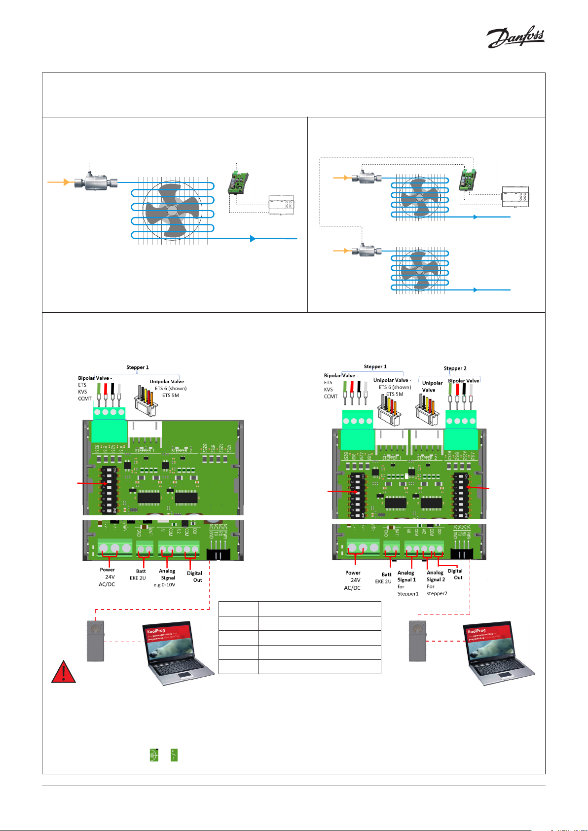
Application
Valve Driver
EKF 1A
ETS Colibri
Connection overview
EKF 1A
1 2 3 4
Analog signal AI1
Digital out
Wire Color scheme
1Green
2 Red
3 Black
4 White
EKF 2A
EKF 2A
ETS Colibri
ETS Colibri
1 2 3 4
1 2 3 4
AI 1
AI 2
Digital out
Dip Switch
Dip Switch1
Dip Switch2
AI1 Analog input 1
COM Common
Koolkey
AI2 Analog input 2 for EKF2A only
Koolkey
COM Common
Koolprog pc tool
DO1 Digital output 1
Koolprog pc tool
• Supports both Bipolar and Unipolar motor.
• Only one connection can be used, either 4 pole terminal block or JST XHP-5 pin connector.
• It is possible to share power supply with 2 EKF and battery backup if battery backup is galvanic isolated and the polarity of power
supply is maintained correct. The same should be observed while sharing power supply with EKF and master controller (AI signal)•
• Connect PE either to the or of power connector. If grounding is done in the transformer do not use EKF grounding connector.
2 | AN375548103097en-000204
© Danfoss | Climate Solutions | 2022.01
Page 3
Quick set up guide
1. Disconnect power to EKF.
2. Connect Valve and Analog signal to the dedicated terminals. Select the Valve via DIP switch 1 to 5.
3. Select the required Analog signal input via DIP switch 7 and 8. For EKF 2A, perform 3 and 4 for both DIP switches.
4. Connect EKF to power and the device is ready to use
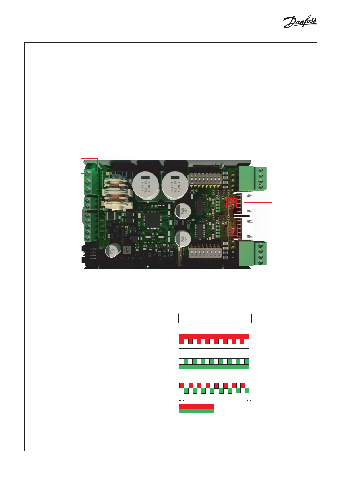
LED indication
Valve
LED for Error/Alarm
LED for Stepper 1
Valve
Two status LED per valve output
Each stepper drive has a set of Red and Green LED
as shown in image. The change in LED light with
the LED indication table can help determine the
valve movement.
RED
RED
GREEN
GREEN
RED
GREEN
RED
GREEN
0s
Power by Koolkey, no valve operation
1s
Valve movement
Valve open circuit
2s
Valve closed
Valve closing
Valve idle on target
Valve idle on target
Valve opening
Valve open
LED for Stepper 2
3 | AN375548103097en-000204
© Danfoss | Climate Solutions | 2022.01
Page 4

Alarm
0 1 2 3 4 5 6 7 8 9 10 11 12 13 14 15
0s
1sec
2sec
RED
GREEN
RED
GREEN
RED
GREEN
RED
GREEN
RED
GREEN
RED
GREEN
RED
GREEN
0
1 1 1 1 1 1 1 1 1 1 1 1 1 1 1 1
1 0
1
1 1 1 1 1 1 1 1 1 1 1 1 1 1 1 1
1
1 1 1 1 1 1 1 1 1 1 1 1 1 1 1 1
1
1 1 1 1 1 1 1 1 1 1 1 1 1 1 1
0
1
1 0
1 1 1 1 1 1 1 1 1 1 1 1 1 1 1 1
1
1 0
1 1 1 1 1 1 1 1 1 1 1 1 1 1 1 1
1
1 0
00
0
0
0
0
1
0
1
0
1 1 1
1
1
0
0
0 0
0
1
0
1
1 1 1 1
0
0
0
0
1 01
00
00
0 0
00 0
1 0
01
1 0
01 0
01
1 0101
01 0
0
0
0
11
1
11
1
1 1 1 1 1 1 1 1
0
0
1
1
0
00
10 1
0
0
01 001
0
10 1
0
0
1
10
0
10
0
0
0
0
0
0
0
0
0
00
1
0
0
0
0
No
Alarm/Warning
Alarm valve 1
Alarm valve 2
Alarm valve 1
+ valve 2
Warning valve 1
Warning valve 2
Warning valve 1
+ valve 2
Alarm/Warning LED
The image shows the position of the alarm/Warning LED.
Alarms has higher priority than warning
~/-
~/+
4 | AN375548103097en-000204
© Danfoss | Climate Solutions | 2022.01
Page 5

DIP switch
The driver has one 8-position DIP switch per stepper motor output.
Note: DIP switch must be changed during POWER OFF only, Any change during power on will not take effect until driver
switches off.
Valve selection
Configure Valve type by selecting DIP switch as shown in table below (green denotes ON).
DIP Switch
Group
Valve
No Valve (Default)
A
1 2 3 4 5 6 7 8
ETS 12C, ETS 24C, ETS 25C, ETS 50C, ETS 100C, KVS 2C,
B
KVS 3C, KVS 5C
ETS 5M
C
ETS 6, UKV, UKV-J
D
ETS12.5, ETS 25, ETS 50, KVS15
E
ETS 100
F
ETS 250, ETS 400, KVS 42
G
Manifold Valves (ETS 500P, ETS 800P)
H
JKV
I
CCMT 2, CCMT4, CCMT8
J
CCMT 16
K
CCMT 24
L
CCMT30
M
CCMT 42
N
CCM 10, CCM 20, CCM 30
O
CCM 40
P
CTR 20
Q
CCMT 3L, CCMT 5L, CCMT 8L, CCMT 10L
R
ETS 175L, ETS 250L, ETS 400L (including oil free
S
application)
Note:
When using Manifold Valves (ETS 500P ad ETS 800P).
Dip switch of driver 1 should be selected to ETS 250/ETS 400.
Dip switch of driver 2 should be selected to Manifold Valves (ETS 500P ad ETS 800P).
See example image of Dip Switch setting
ETS 12C selected
ETS 12C with 0-5 V AI input
0-5 V AI input 0-10 V AI input
5 | AN375548103097en-000204
ETS 12C with 0-10 V AI input
© Danfoss | Climate Solutions | 2022.01
Page 6

Analog input selection
Congure Analog signal type by selecting DIP switch as shown in below table (green denotes ON).
Analog Input DIP Switch
1 2 3 4 5 6 7 8
0 - 10 V (Default)
0 - 5 V
4 - 20 mA
0 - 20 mA
Analog input sharing
Congure analog input to be shared if needed as below (green denotes ON).
Stepper driver 1
Analog Input AI1
Analog input AI2
1 2 3 4 5 6 7 8
DIP Switch
Stepper driver 2
Analog Input AI1
Analog input AI2
Digital output signal
One digital output is present in EKF and only alarm activates the output.
Output type Similar to NPN, open collector
Load type Resistive only
Maximum allowed current 10 mA
Maximum Voltage 28 V (allow 24 V DC + 15%)
Stepper Motor Output
• The stepper motor is connected to the “Stepper Valve” terminals (see connection overview) with a standard M12
connection cable or JST XHP-5 connector.
• The default valve setting in EKF 1A/2A is: No Valve.
• The correct valve must be dened as per section DIP Switch – Valve
Valve Cable Connection
Danfoss recommends to use ETS 5M and ETS 6 valves to be connected to JST XHP-5 pin connectors instead of 4 pole terminal
block, but it is possible to connect to terminal block, follow color codes of wires of coil as shown in table below.
Stepper valve ETS/KVS/CCM/ CCMT/CTR/ CCMT L ETS 5M ETS 6
A1 White Brown Orange
A2 Black Black Yellow
B1 Red Orange Red
B2 Green Yellow Black
1 2 3 4 5 6 7 8
DIP Switch
While using JST 5pin, its plug and play for ETS 6 and ETS 5M valves.
Guideline for long M12 cables for Danfoss stepper motor valves
• Long cables will lead to degradation of performance.
• Cable length for stepper motor connection must be less than 30 m.
• Danfoss recommends to use 4-20 mA signal for long distances and use shorter cable between driver and valve.
6 | AN375548103097en-000204
© Danfoss | Climate Solutions | 2022.01
Page 7

General features and Warnings
Plastic housing:
• DIN rail mounting complying with EN 60715
• Self-extinguishing V0 according to IEC 60695-11-10 and glowing/hot wire test at 960 °C according to IEC 60695-2-12
CE COMPLIANCE
- Operating conditions CE: -20T60, 90% RH non-condensing
- Storage conditions: -30T80, 90% RH non-condensing
- Electromagnetic compatibility EMC: 2014/30/EU with the following norms,
- EN 61000-6-2:2005, Generic standards - Immunity for industrial environments (AC and DC voltage supply)
- EN 61000-6-3+A1:2011 and EN 61000-6-3:2007, Generic standards - Emission standard for residential, commercial and
light-industrial environments (DC voltage supply only)
- EN 61000-6-4:2019 and EN 61000-6-4:2007+A1, Generic standards – Emission standard for industrial environments
(AC and DC voltage supply)
GENERAL WARNINGS
- Every use that is not described in this manual is considered incorrect and is not authorized by the manufacturer
- Verify that the installation and operating conditions of the device respect those specied in the manual, especially concerning the
supply voltage and environmental conditions
- All service and maintenance operations must be performed by qualied personnel
- The device must not be used as a safety device
- Liability for injury or damage caused by the incorrect use of the device lies solely with the user
INSTALLATION WARNINGS
- Recommended mounting position: vertical
- Installation must comply with local standards and legislation
- Before working on the electrical connections, disconnect the device from the main power supply
- Before carrying out any maintenance operations on the device, disconnect all electrical connections
- For safety reasons the appliance must be tted inside an electrical panel with no live parts accessible
- Do not expose the device to water sprays or to a relative humidity greater than 90%.
- Avoid exposure to corrosive or pollutant gases, natural elements, environments where explosives or mixes of
ammable gases are present, dust, strong vibrations or shock, large and rapid uctuations in ambient temperature
that might cause condensation in combination with high humidity, strong magnetic and/or radio interference
(e.g. transmitting antennae)
- Use cable ends suitable for the corresponding connectors. After tightening connector screws, tug the cables gently to check their
tightness
- Minimize the length of probe and digital input cables as much as possible, and avoid spiral routes around power
devices. Separate from inductive loads and power cables to avoid possible electromagnetic noises
- Avoid touching or nearly touching the electronic components on the board to avoid electrostatic discharges
PRODUCT WARNINGS
• Use a class II power supply.
• Connecting any EKF ports to mains voltage will permanently damage the controller.
• Battery backup terminals do not generate power to recharge a device connected.
• Battery backup - the voltage will close the stepper motor valves if the controller loses its supply voltage.
7 | AN375548103097en-000204
© Danfoss | Climate Solutions | 2022.01
 Loading...