

Page 1
User Guide
Stepper valve driver
Type EKF 1A, EKF 2A
Driver for stepper motor valves SW V1.24
Page 2

Stepper valve driver, type EKF 1A, EKF 2A
Introduction
Stepper valve driver EKF series is used where stepper valves must be accurately controlled typically in commercial
air conditioning, heat pumps, commercial refrigeration and food retail applications.
Features
• Support both Bipolar and Unipolar stepper motor valves
• Driven by analog input signal
• Fast installation and setup
• Lost step prevention
• Open circuit detection
• LED indication for valve movement and alarm/warnings
• On board DIP switch for quick selection
• Plug and play
• 4 pole terminal block and JST-XHP 5 pin connections
• Phoenix connector terminals
• Digital output for alarm signal
• 1 and 2 valve driver version available
© Danfoss | Climate Solutions | 2022.03 BC387326840736en-000102 | 2
Page 3
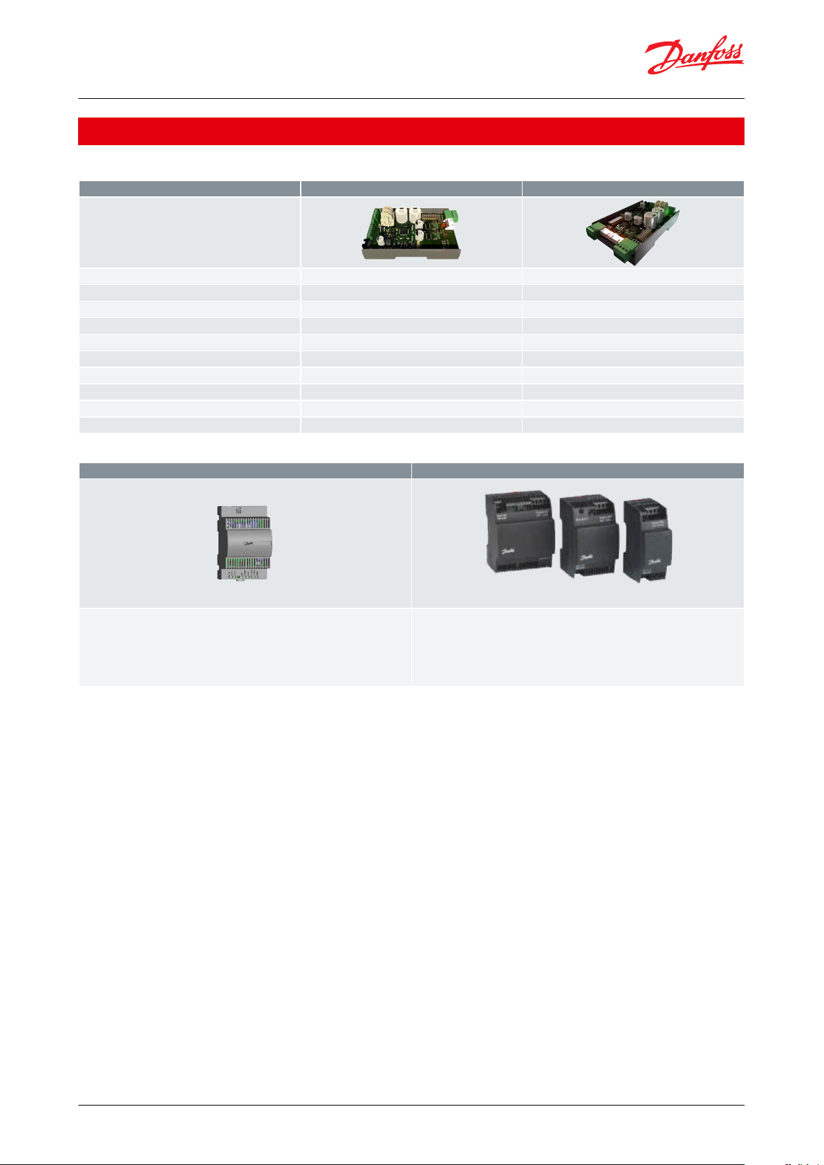
Features
EKF 1A
EKF 2A
Code number
080G5030
080G5035
Power supply
24 V AC/DC
24 V AC/DC
Number of valves
1 stepper motor valve
2 stepper motor valves
Valve type
Unipolar/Bipolar
Unipolar/Bipolar
Analog inputs
1
2
Digital outputs
1
1
Dip switch
1
2
Battery backup support
Yes
Yes
Mounting
35 mm, 4 DIN
35 mm, 4 DIN
Dimension (H x W)(mm)
110 x 70
110 x 70
EKE 2U Backup power module
Power supply
EKE 2U Backup power module ensures sucient power in case of power failures
to the controller / driver to ensure closure of the electronic valves.
AK-PS
Input: 100 - 240 V AC/45 - 65 Hz
Output: 24 V DC: available with 18 VA, 36 VA and 60 VA
ACCTRD
Input: 230 V AC, 50 - 60 Hz
Output: 24 V AC, available with 12 VA, 22 VA and 35 VA
Stepper valve driver, type EKF 1A, EKF 2A
Portfolio overview
Table 1: Portfolio overview
Table 2: Related Products
© Danfoss | Climate Solutions | 2022.03 BC387326840736en-000102 | 3
Page 4
AI1
AI2
Unit
programmable
controller
ETS Colibri
AI1
Digital out
ETS Colibri
AI1
AI2
ETS Colibri
Digital out
Unit
programmable
controller
Analog input signal 1
Analog input signal 2
Stepper valve driver, type EKF 1A, EKF 2A
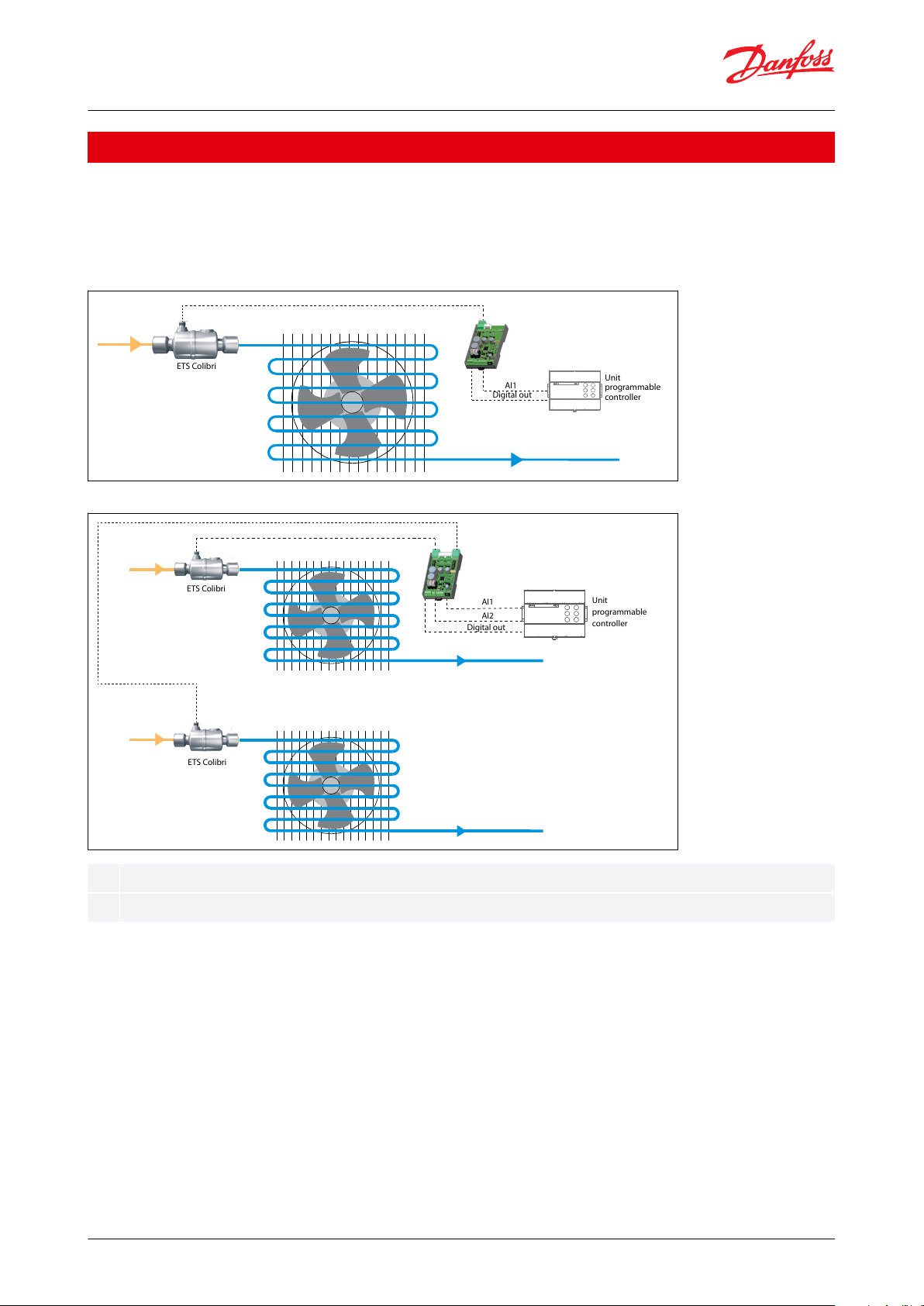
Applications
EKF series stepper valve drivers can be used in application where accurate control of stepper motor valves are
needed using analog input signals (0-10V, 0-5V, 4-20 mA, 0-20 mA) from unit programmable controllers. The
product can be used for both Bipolar and Unipolar type valves. General applications include use in commercial air
conditioning, heat pumps, commercial refrigeration and food retail application
Figure 1: EKF 1A
Figure 2: EKF 2A
© Danfoss | Climate Solutions | 2022.03 BC387326840736en-000102 | 4
Page 5
Either JST or 4
pin should be
used
JST XHP 5
pin for ETS
5m & ETS 6
M12 cable from
stepper motor
to 4 pin
terminal
For stepper Valve 1
output
stepper Valve 1 DIP
SWITCH
EKE 2U Battery Backup
Koolkey
24V ± 20%
AC/DC
supply
source
Battery connection
KoollProg PC tool
Digital Output (DO) -> Relay/PLC
Analog Input (Al1), [0-5V, 0-10V, 0-20mA, 4-20mA
M12 cable from
stepper motor
to 4 pin
terminal
Either JST or 4
pin should be
used
JST XHP 5 pin
for ETS 5m &
ETS 6
For stepper Valve 1
output
stepper Valve 1 DIP
SWITCH
24V ± 20%
AC/DC
supply
source
Battery connection
KoollProg PC tool
Koolkey
Digital Output (DO) -> Relay/PLC
Analog Input (Al1), [0-5V, 0-10V, 0-20mA, 4-20mA
Analog Input (Al2), [0-5V, 0-10V, 0-20mA, 4-20mA
For stepper Valve 2
output
stepper Valve 2 DIP
SWITCH
Stepper valve driver, type EKF 1A, EKF 2A
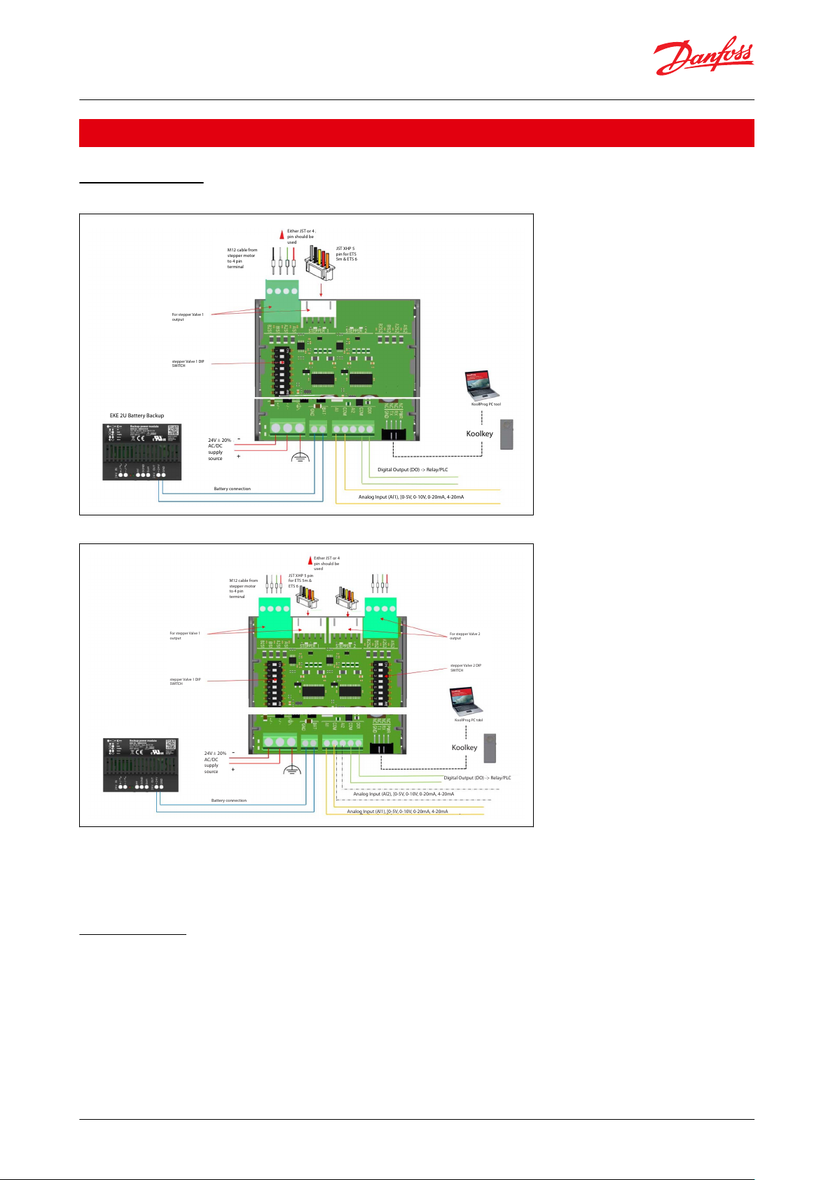
Installation
Wiring terminals
Figure 3: EKF 1A
Figure 4: EKF 2A
NOTE:
There are both 4 pin terminal and JST 5 pin terminal available on the board per stepper drive output.
Only one of the terminals should be used per valve.
Do not connect valves to both 4 pin terminal and JST terminal of the same stepper driver output.
Power sharing
EKF can share power from the same source with a battery backup or unit controller only if battery backup/unit
controller ports are galvanically isolated.
Danfoss recommends to use EKE 2U as the preferred battery backup device.
NOTE:
EKE 2U can only support 2 valves for emergency closing, thus EKE 2U should not be shared with more than one EKF
2A or more than two EKF 1A.
© Danfoss | Climate Solutions | 2022.03 BC387326840736en-000102 | 5
Page 6
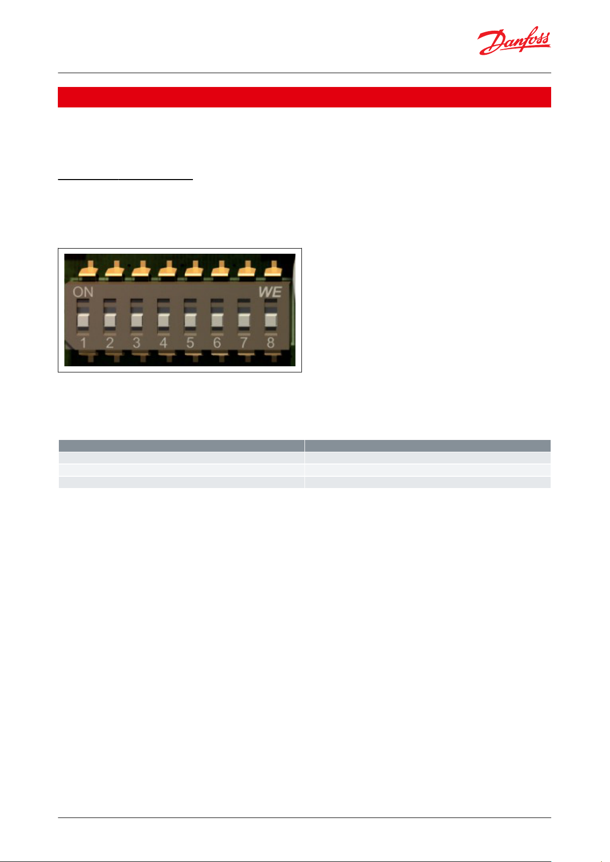
Switch numbers
Selection
Switch 1-5
Valve selection
Switch 6
Analog sharing selection
Switch 7 & 8
Analog signal selection
Stepper valve driver, type EKF 1A, EKF 2A
Conguration
EKF can be congured using
1.
DIP switch
2.
Koolkey & KoolProg PC tool
DIP Switch conguration
The basic product conguration can be done through DIP switch present on the hardware.
EKF 1A supports 1 stepper drive output and 1 Dip switch for settings.
EKF 2A supports 2 stepper drive output and 2 Dip switch for settings.
Figure 5: DIP switch
The image above shows a schematic of a dip switch
Each DIP switch consists of 8 switches.
The below table shows what each Dip switch section represents.
Table 3: Dip switch section
Steps to follow to congure EKF using Dip switch:
1.
Disconnect the EKF from power supply.
2.
Connect the valves and AI inputs to EKF.
3.
Make the needed settings on the EKF dip switch.
4.
Turn the power back on to EKF.
5.
EKF is ready to use with the new settings
NOTE:
Any changes made to EKF dip switch while EKF is powered ON will result in warning and the new settings are not
active. In case of the above error switch the power OFF and then ON the EKF. The newly made settings will now be
active.
The tables below can be used to help select dip switch positions.
Valve selection (Switch 1-5)
Green denotes ON position of DIP switch
© Danfoss | Climate Solutions | 2022.03 BC387326840736en-000102 | 6
Page 7
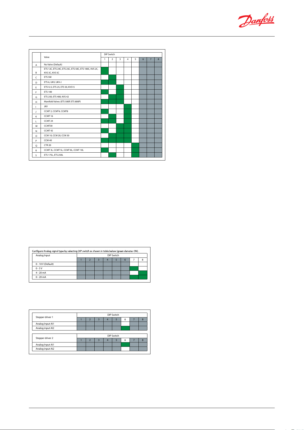
Valve
DIP Switch
1 2 3 4 5 6 7 8
A
No Valve (Default)
B
ETS 12C, ETS 24C, ETS 25C, ETS 50C, ETS 100C, KVS 2C,
KVS 3C, KVS 5C
C
ETS 5M
D
ETS 6, UKV, UKV-J
E
ETS12.5, ETS 25, ETS 50, KVS15
F
ETS 100
G
ETS 250, ETS 400, KVS 42
H
Manifold Valves (ETS 500P, E TS 800P)
I
JKV
J
CCMT 2, CCMT4, CCMT8
K
CCMT 16
L
CCMT 24
M
CCMT30
N
CCMT 42
O
CCM 10, CCM 20, CCM 30
P
CCM 40
Q
CTR 20
R
CCMT 3L, CCMT 5L, CCMT 8L, CCMT 10L
S
ETS 175L, ETS 250L
Analog Input DIP Switch
1 2 3 4 5 6 7 8
0 - 10 V (Default)
0 - 5 V
4 - 20 mA
0 - 20 mA
Stepper driver 1
DIP Switch
1 2 3 4 5 6 7 8
Analog Input AI1
Analog input AI2
Stepper driver 2
DIP Switch
1 2 3 4 5 6 7 8
Analog Input AI1
Analog input AI2
Stepper valve driver, type EKF 1A, EKF 2A
Figure 6: DIP valve section
NOTE:
Only applicable for EKF 2A When using Manifold valves.
Dip switch 1 for stepper driver 1 should be selected to base valve type.
Eg: ETS C should be selected in Dip switch 1 if ETS Colibri is used in manifold operation.
ETS 250/400 should be selected if using ETS 500P/ETS 800P.
Dip switch 2 for stepper driver 2 should be selected as manifold valve (Group H).
While setting Dip switch 2 as manifold valve EKF automatically recognize that it is using only 1 Analog input to
control both valves and by default AI1 is used as the analog input. Analog sharing function is automatically
activated.
Analog input selection (Switch 7 & 8)
Green denotes ON position of DIP switch
Figure 7: DIP analog input selection
Analog sharing selection (Switch 6)
Green denotes ON position of DIP switch
Figure 8: DIP analog sharing selection
NOTE:
Analog sharing is used only in EKF 2A.
Analog sharing can be done to run 2 valves using the same analog input.
If stepper driver 1 should use analog input from AI2 (AI2 is meant for stepper driver 2 analog input).
Then Dip switch 1 should have switch 6 at position ON.
EKF 2A will then use AI2 signal to control stepper valve 1.
If stepper driver 2 should use analog input from AI1 (AI1 is meant for stepper driver 1 analog input).
© Danfoss | Climate Solutions | 2022.03 BC387326840736en-000102 | 7
Page 8
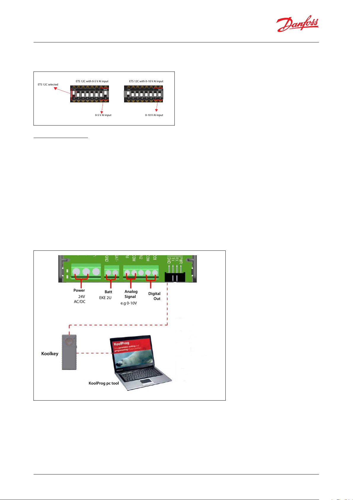
ETS 12C with 0-5 V AI input
ETS 12C selected
ETS 12C with 0-10 V AI input
0-5 V AI input
0-10 V AI input
Power
Batt
Analog
Signal
Digital
Out
KoolProg pc tool
Koolkey
24V
AC/DC
EKE 2U
e.g 0-10V
Stepper valve driver, type EKF 1A, EKF 2A
Then Dip switch 2 should have switch 6 at position ON.
EKF 2A will then use AI1 signal to control stepper valve 2.
Figure 9: DIP switch setting
Connecting to PC
EKF Series stepper drivers can be connected to PC for
1.
Accessing and changing advanced settings
2.
Accessing alarm/warning and diagnostic readouts
3.
Performing service
If the advanced parameter settings are not needed, the product can be set using Dip switch only.
While using the Dip switch option a connection to PC is not required.
To connect EKF to pc the below tools are needed
1.
KoolProg PC software (Check KoolProg website if the version supports EKF)
2.
Koolkey
3.
Cables to connect Koolkey to PC and EKF(available as Koolkey accessory)
The schematic below shows how to connect EKF with Koolkey and PC
Figure 10: EKF with Koolkey and PC
Steps to follow while connecting EKF to KoolProg:
1.
Connect EKF to power, make sure power is ON
2.
Connect Valve and input signals to EKF.
3.
Connect Koolkey to EKF and PC
4.
Select On-line service option in Koolprog.
5.
Select SW Main switch to OFF
© Danfoss | Climate Solutions | 2022.03 BC387326840736en-000102 | 8
Page 9

Stepper valve driver, type EKF 1A, EKF 2A
6.
Make necessary changes to parameters from drop down lists.
7.
After completing all changes set SW Main switch to ON.
8.
EKF is ready to use with the new settings.
Figure 11: On-line service
NOTE:
To make changes to the settings of EKF using Koolkey/KooProg software, the SW main switch should be OFF.
By default EKF looks at DIP switch for the settings. If settings are altered to use values for Koolprog then EKF will look
at Koolprog settings only and not follow changes in DIP switch. To use DIP switch again, EKF should be changed
back to use DIP switch settings using Koolprog
EKF can be congured using PC with the use of Koolkey and Koolprog PC tool.
The KoolProg tool should be used for making advanced selection and setting of EKF.
There are 2 main sections in Koolprog for EKF conguration:
1.
Basic setting
2.
Valve driver setting
Basic setting
Figure 12: Basic setting
Basic setting – Generic
Main Switch - Main
Main switch should be OFF while making changes to parameters and must be turned back ON to have the settings
made active.
Battery alarm enable – B000
This parameter should be used to set battery alarm ON/OFF.
Turning it on will enable alarm through DO(Digital output) when battery voltage is low.
Factory reset – B001
This parameter should be used to factory reset EKF, When full reset of all parameters are required
Relay position – B002
This parameter should be kept at position Auto.
There is an option to force open and close the alarm.
This parameter should be used as service test to see if alarm activates and communicates through DO (Digital
output).
Basic setting – Driver
© Danfoss | Climate Solutions | 2022.03 BC387326840736en-000102 | 9
Page 10

Stepper valve driver, type EKF 1A, EKF 2A
Driver enabling – B100
This parameter should be used to turn ON/OFF driver output.
When OFF is selected EKF will not drive valve connected to corresponding stepper output.
Valve selection – B101
This parameter is used to select which valve the stepper output is connected to and which setting
(DIP switch or KoolProg) that EKF has to follow.
When set to Dip switch EKF reads the setting made on DIP switch.
When set to User dened, Additional parameters will be visible in valve driver setting.
This should be used when conguring valves that are not preset into EKF.
When set to groups, EKF will recognize the valves according to the group naming
Valve position mode – B102
This parameter is used to select which input EKF should use to position the valve.
When selecting from AI, EKF will read the AI input and move valve accordingly.
When selecting from register, an additional parameter valve position will be visible.
According to the valve position % (OD%) EKF will move the valve.
Figure 13: Basic setting - Driver1
NOTE:
Valve position mode: From register is only used for service and check purpose.
Basic setting – Valve analog input
AI selection -B104
This parameter is used to set if EKF has to use Dip switch for AI selection or from Koolprog.
When selected to Dip switch EKF will read the dip switch setting.
When selected to other inputs from drop down list EKF will not read from Dip switch instead will use setting
selected here.
AI calibration oset V - B105
This parameter is used to oset 0 - 10 V, 0 - 5 V AI input signal
AI calibration oset mA – B106
This parameter is used to oset 4 - 20 mA, 0 - 20 mA AI input signal
Figure 14: Valve driver setting
© Danfoss | Climate Solutions | 2022.03 BC387326840736en-000102 | 10
Page 11
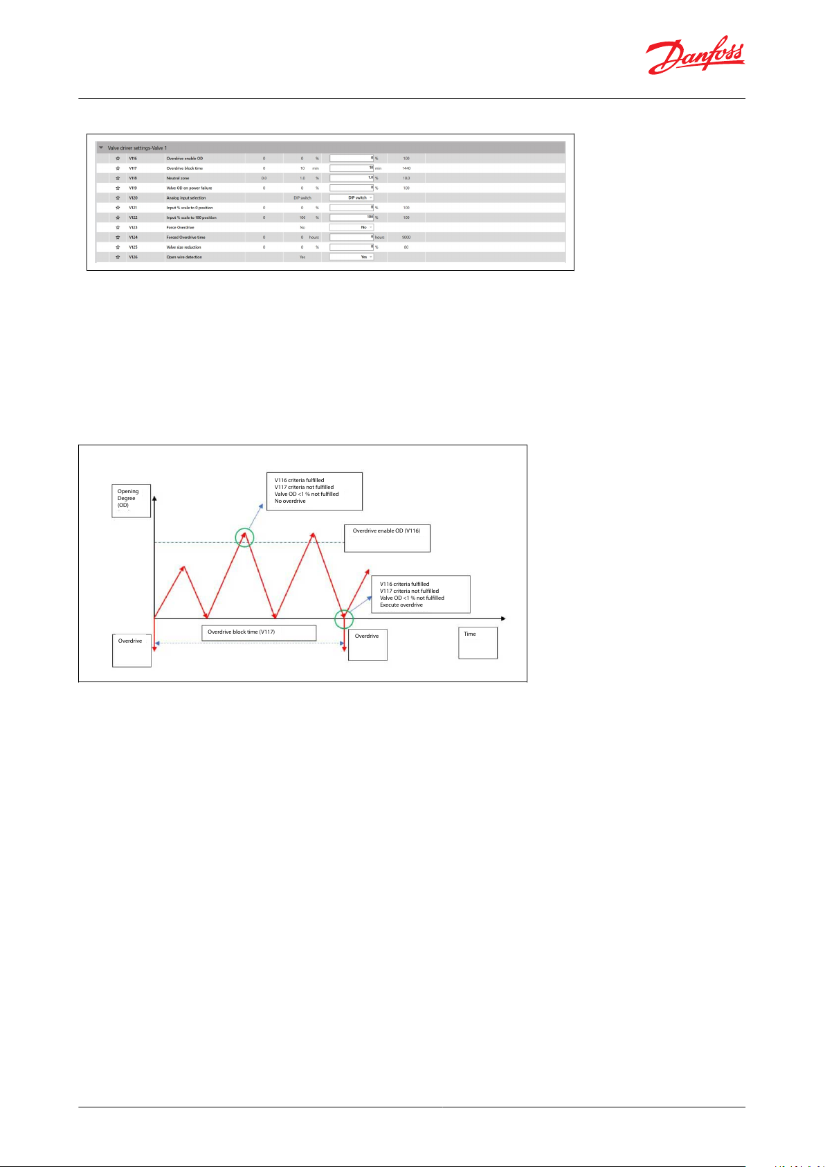
Opening
Degree
(OD)
Overdrive
Overdrive
Time
Overdrive block time (V117)
Overdrive enable OD (V116)
V116 criteria fulfilled
V117 criteria not fulfilled
Valve OD <1 % not fulfilled
No overdrive
V116 criteria fulfilled
V117 criteria not fulfilled
Valve OD <1 % not fulfilled
Execute overdrive
Stepper valve driver, type EKF 1A, EKF 2A
Figure 15: Valve driver setting - valve 1
Overdrive
Overdrive features are necessary to help driver calibrate the valve position and prevents accumulation of loss of
step.
Overdrive will close the valve with extra number of steps towards closing direction.
The number of additional steps for overdrive is valve depended. While using Danfoss valves from
valve selection list number of steps for overdrive is automatically set.
For third party products this should be set as a parameter inside user dened valve.
Excess overdrive will increase valve wear rate.
Figure 16: EKF overdrive
Overdrive enable OD – V116
This parameter denes the opening degree that triggers an overdrive. If the actual opening degree of the valve
crosses the overdrive enable OD then the driver will be ready for an overdrive the next time the valve actual
opening degree reaches below 1% opening degree
Overdrive block time - V117
This parameter denes the time block between 2 consecutive overdrives
Neutral zone – V118
Valve neutral zone limits the driver from moving the valve from its position if the dierential between the current
valve position to the new position of the valve is within this percentage. This limits the valve from changing position
for small variations in incoming analog signals
By defualt Neutral zone is 1% that is any change in valve opening degree from reference of +0.5% will not move the
valve. Any change above this band will move the valve to the new position.
© Danfoss | Climate Solutions | 2022.03 BC387326840736en-000102 | 11
Page 12

Opening
Degree
(OD)
Overdrive
Forced overdrive time V124
Overdrive
Time
Valve position back as per
AI signal
V123 = Yes
V124 criteria fulfilled
Execute overdrive
Stepper valve driver, type EKF 1A, EKF 2A
Figure 17: Forced overdrive
Forced Overdrive – V123
Forced overdrive is use to trigger an overdrive purely based on time. The driver will move the valve to 0 position
with overdrive and immediately come back to the requested position from analog signal
Forced overdrive time – V124
Forced overdrive time is a timer for forced overdrive.
Forced overdrive has highest priority and will overrule overdrive block time V117.
Overdrive block time V117 will be reset after forced overdrive is made.
After forced overdrive valve will return back to last position.
Valve OD on power failure – V119
This parameter sets the opening degree to which the driver should position the valve during an emergency closing
has been done due to power failure
Analog input selection – V120
This parameter is used to select which analog input signal EKF should use to position the valve. If Dip switch is
selected then EKF will read the settings made at dip switch else it will use as per the selection made in software.
Valve scaling
EKF has parameter that can scale valve opening degree to the input analog signal.
Input % scale to 0 position – V121
In normal operation EKF will linearly control valve from 0 – 100 % opening degree corresponding to 0 – 10 V analog
signal.
When input scaling is done from 0 position the Analog input is scaled towards this range.
Eg: If V121 is 0 then valve will move 0 – 100% opening degree with 0 – 10 V.
If V121 is 10 then valve will move 10 – 100% opening degree with 0 – 10 V
Input % scale to 100 position – V122
In a normal operation EKF will linearly control valve from 0 – 100 % opening degree corresponding to 0 – 10 V
analog signal.
When input scaling is done from 100 position the Analog input is scaled towards this range.
Eg: If V122 is 100 then valve will move 0 – 100% opening degree with 0 – 10 V.
If V121 is 90 then valve will move 0 – 90% opening degree with 0 – 10 V
Valve size reduction - V125
This parameter can help reduce oversized valves in application.
If V125 is 0 then valve size is 0 – 100% of opening degree
If V125 is 10 then valve size is 0 – 90% of opening degree
© Danfoss | Climate Solutions | 2022.03 BC387326840736en-000102 | 12
Page 13

V125 - Valve Size reduction
V121 - Input % scale to 0 position
V122 - Input % scale to 100 position
V120 - Analog input selection
B105 AI calibration offset V
B106 AI calibration offset mA
AI = 0-100%
OD% = scaled by Ai
(limit: 0-100%)
Step = OD% * steps *
size%
Valve steps
0-10V / 0-20mA
V122 - Scale 100 pos.
100
0
0
100
V121 - Scale 100 pos.
10-0V for 0-100% valveOD
Valve 1: 0-6V for 0-100%
Default: 0-10 for 0-100% valveOD
Valve 2: 5,5V - 10V for 0-100%
OD%
AI %
Stepper valve driver, type EKF 1A, EKF 2A
Figure 18: EKF valve
Open wire detection – V126
This parameter is used to switch on and o the open wire detection. This helps detect if there is any open wire or
discontinuity in stepper coil connection
© Danfoss | Climate Solutions | 2022.03 BC387326840736en-000102 | 13
Page 14

Label
Description
Min
Max
Value (Defualt)
Unit
Enumeration
Notes
DRIVER 1
B100
Driver enabling
1 = On
0=O;1=On
0:Parameter conguration allowed for update; 1:Normal operation
B101
Valve selection
0 = DIP Switch
DIP switch, User dened,
Group B, Group C, Group D,
Group E, Group F, Group G,
Group H, Group I, Group J,
Group K, Group L, Group M,
Group N, Group O, Group P,
Group Q, Group R, Group S
0:Valve selection by DIP switch;
1 – 19:DIP switch set by parameter
B102
Valve positioning mode
0 = From AI
0=From AI;1=From register
0:Analog input; 1:parameter
B103
B103
Valve position
0
1000%
Manual opening degree set by
parameter (B102 = AI)
ANALOG INPUT 1
B104
AI selection
0 = DIP switch
0=DIP switch;1=0 – 10 V; 2=0
– 5 V; 3=4 – 20 mA; 4=0 – 20
mA
0:Type selection by DIP switch; 1
– 4: Type selection by parameter
B105
AI calibration oset V
-110
V
Oset added to measured signal
B106
AI calibration oset mA
-220
mA
Oset added to measured signal
DRIVER 2
B200
Driver enabling
1 = On
0=O;1=On
0:Parameter conguration allowed for update; 1:Normal operation
B201
Valve selection
0 = DIP Switch
DIP switch, User dened,
Group B, Group C, Group D,
Group E, Group F, Group G,
Group H, Group I, Group J,
Group K, Group L, Group M,
Group N, Group O, Group P,
Group Q, Group R, Group S
0:Valve selection by DIP switch;
1 – 31:DIP switch set by parameter
B202
Valve positioning mode
0 = From AI
0=From AI;1=From register
0:Analog input; 1:parameter
B203
B203
Valve position
0
1000%
Manual opening degree set by
parameter (B202 = AI)
ANALOG INPUT 2
B204
AI selection
0 = DIP switch
0=DIP switch; 1=0 – 10 V;
2=0 – 5 V; 3=4 – 20 mA; 4=0
– 20 mA
0:Type selection by DIP switch; 1
– 4: Type selection by parameter
B205
AI calibration oset V
-110
V
Oset added to measured signal
B206
AI calibration oset mA
-220
mA
Oset added to measured signal
GENERIC
B000
Battery alarms enable
0 = O
0=O;1=On
0:No Alarm; 1:Alarm based on
battery voltage
B001
Factory reset
0 = No
0=No;1=Yes
0:No; 1:Yes,Reset all parameters
to factory settings
B002
Relay position
0 = Auto
0=Auto;1=Open;2=Close
Label
Description
Min
Max
Value (Defualt)
Unit
Enumeration
Notes
VALVE 1
V100
User dened Motor type
0 = Unipolar
0=Unipolar; 1=Bipolar
Type of motor used in the stepper valve (Unipolar/Bipolar).
V101
User dened Decay mode
0 = Fast
0=Fast; 1=Slow; 2=Mixed
Fast decay mode causes a rapid
reduction in inductive current
and allows the motor to coast
toward zero velocity. Slow decay mode leads to a slower reduction in inductive current but
produces rapid deceleration.
Stepper valve driver, type EKF 1A, EKF 2A
Parameters
Table 4: BASIC SETTING
Table 5: VALVE DRIVER SETTINGS
© Danfoss | Climate Solutions | 2022.03 BC387326840736en-000102 | 14
Page 15

Label
Description
Min
Max
Value (Defualt)
Unit
Enumeration
Notes
V102
User dened Step mode
0 = Full
0=Full; 1=Half; 2=1/4; 3=1/8;
4=1/16
Danfoss recommends using 1/8
stepping mode as this provides
a good balance between torque
and speed and ensures smooth
operation.
V103
User dened Step positioning
2 = Auto
0=Fullstep;1=Halfstep;2=Auto
V104
User dened Total steps
0
100000stp
The total no of steps will vary
according to the selected valve
motor type, always referring to
full steps.
V105
User dened Speed
10
30010pps
Desired valve speed drive rate
in steps per second.
V106
User dened Start speed
100
100
100
%
Valve Start Speed (1 – 100% of
Valve speed)
V107
User dened Emengency
speed
50
200
100
%
Emergency close is in use when
the main power is lost, and the
valve is closed using the battery
backup
V108
User dened Drive current
10
100010mA
Current applied to each phase
of the stepper motor during actual valve movement.
V109
User dened Acceleration
current
100
100
100
%
Current supplied to the coils under acceleration of the stepper
motor
V110
User dened Acceleration
time
101010
ms
Time used to get from min
speed to normal speed
V111
User dened Holding current
0
1000%
Percent of Max Phase Current
that should be applied to each
phase of the stepper output
when the valve is stationary.
V112
User dened Valve excitation time after stop
0
100010ms
Time that the drive current is
continued after the motor has
stopped movement. Next state
is holding current.
V113
User dened Compensation backlash
0100
%
Number of steps needed to correct for mechanical hysteresis
when a reduction gear is part of
the valve design
V114
User dened Valve thermal protection
0
100
100
%
For Danfoss valves don't
changemaximum - allowed dutycycle
V115
User dened Overdrive
0205
%
Extra steps for zerocalibrating
valve possition, scaled as a percentage of the full opening.
V116
Overdrive enable OD
0
1000%
Denes how much the valve
must have been open before
overdrive is allowed at next
close position
V117
Overdrive block time
0
144010min
Denes the minimum time between two overdrive actions.
Overdrive calibrations within
this time frame will be ignored.
V118
Neutral zone
0101
%
Dene how much the requested
OD must change before a new
OD is set.
V119
Valve OD on power failure
0
1000%
Move the valve to a predened
position during power failure
V120
Analog input selection
0 = DIP switch
0=DIP switch; 1=AI 1; 2=AI 2
0:DIP switch; 1:AI 1; 2: AI 2
V121
Input % scale to 0 position
0
1000%
Signal type is dened by “B104”
“AI selection”
V122
Input % scale to 100 position
0
100
100
%
Signal type is dened by “B104”
“AI selection”
V123
Force Overdrive
0 = No
0=No;1=Yes
Manually initiate an overdrive.
NOTE this will close the valve for
some tome
V124
Forced Overdrive time
0
90000hours
Timer based overdrive. If no
overdrive has been performed
within this period, then a valve
close is done (forced overdrive)
V125
Valve size reduction
0800
%
V126
Open wire detection
1 = Yes
0=No; 1=Yes
Stepper valve driver, type EKF 1A, EKF 2A
© Danfoss | Climate Solutions | 2022.03 BC387326840736en-000102 | 15
Page 16

Label
Description
Min
Max
Value (Defualt)
Unit
Enumeration
Notes
VALVE 2
V200
User dened Motor type
0 = Unipolar
0=Unipolar; 1=Bipolar
Type of motor used in the stepper valve (Unipolar/Bipolar).
V201
User dened Decay mode
0 = Fast
0=Fast; 1=Slow; 2=Mixed
Fast decay mode causes a rapid
reduction in inductive current
and allows the motor to coast
toward zero velocity. Slow decay mode leads to a slower reduction in inductive current but
produces rapid deceleration.
V202
User dened Step mode
0 = Full
0=Full; 1=Half; 2=1/4; 3=1/8;
4=1/16
Danfoss recommends using 1/8
stepping mode as this provides
a good balance between torque
and speed and ensures smooth
operation.
V203
User dened Step positioning
2 = Auto
0=Fullstep; 1=Halfstep;
2=Auto
V204
User dened Total steps
0
100000stp
The total no of steps will vary
according to the selected valve
motor type, always referring to
full steps.
V205
User dened Speed
10
30010pps
Desired valve speed drive rate
in steps per second.
V206
User dened Start speed
100
100
100
%
Valve Start Speed (1 – 100% of
Valve speed)
V207
User dened Emengency
speed
50
200
100
%
Emergency close is in use when
the main power is lost, and the
valve is closed using the battery
backup
V208
User dened Drive current
10
100010mA
Current applied to each phase
of the stepper motor during actual valve movement.
V209
User dened Acceleration
current
100
100
100
%
Current supplied to the coils under acceleration of the stepper
motor
V210
User dened Acceleration
time
101010
ms
Time used to get from min
speed to normal speed
V211
User dened Holding current
0
1000%
Percent of Max Phase Current
that should be applied to each
phase of the stepper output
when the valve is stationary.
V212
User dened Valve excitation time after stop
0
100010ms
Time that the drive current is
continued after the motor has
stopped movement. Next state
is holding current.
V213
User dened Compensation backlash
0100
%
Number of steps needed to correct for mechanical hysteresis
when a reduction gear is part of
the valve design
V214
User dened Valve thermal protection
0
100
100
%
For Danfoss valves don't
changemaximum - allowed dutycycle
V215
User dened Overdrive
0205
%
Extra steps for zerocalibrating
valve possition, scaled as a percentage of the full opening.
V216
Overdrive enable OD
0
1000%
Denes how much the valve
must have been open before
overdrive is allowed at next
close position
V217
Overdrive block time
0
144010min
Denes the minimum time between two overdrive actions.
Overdrive calibrations within
this time frame will be ignored.
V218
Neutral zone
0101
%
Dene how much the requested
OD must change before a new
OD is set.
V219
Valve OD on power failure
0
1000%
Move the valve to a predened
position during power failure
V220
Analog input selection
0 = DIP switch
0=DIP switch; 1=AI 2; 2=AI 1
0:DIP switch; 1:AI 2; 2: AI 1
V221
Input % scale to 0 position
0
1000%
Signal type is dened by “B204”
“AI selection”
Stepper valve driver, type EKF 1A, EKF 2A
© Danfoss | Climate Solutions | 2022.03 BC387326840736en-000102 | 16
Page 17

Label
Description
Min
Max
Value (Defualt)
Unit
Enumeration
Notes
V222
Input % scale to 100 position
0
100
100
%
Signal type is dened by “B204”
“AI selection”
V223
Force Overdrive
0 = No
0=No; 1=Yes
Manually initiate an overdrive.
NOTE this will close the valve for
some tome
V224
Forced Overdrive time
0
90000hours
Timer based overdrive. If no
overdrive has been performed
within this period, then a valve
close is done (forced overdrive)
V225
Valve size reduction
0800
%
V226
Open wire detection
1 = Yes
0=No; 1=Yes
Label
Description
Min
Max
Value (Defualt)
Unit
Enumeration
Notes
DRIVER 1
R100
Valve position
0
1000%
Actual valve possition
R101
Analog input signal
0
200000uA/mV
Actual analog input signal
DRIVER 2
R200
Valve position
0
1000%
Actual valve possition
R201
Analog input signal
0
200000uA/mV
Actual analog input signal
GENERIC
R000
Battery voltage
0
300000mV
Measured battery voltage
R001
Software version high
0
65535
0
Software version high.low (the
integer part)
R002
Software version low
0
65535
0
Software version high.low (the
decimal part)
Stepper valve driver, type EKF 1A, EKF 2A
Table 6: READOUTS
© Danfoss | Climate Solutions | 2022.03 BC387326840736en-000102 | 17
Page 18

Function Data
Value
Supply Voltage
EKF 1A: 24 V AC / DC 50 / 60 Hz
EKF 2A: 24 V AC / DC, 50 / 60 Hz
Power consumption
Idle operating: < 1 W (without valve)
Power consumption for using 1 valve. CCMT 16 –
CCMT 42: 25 VA / 15 W
ETS 5M, ETS 6: 20 VA / 10 W
ETS 12C – ETS 100C, KVS C: 30 VA /15 W
ETS 12.5 – 400: 10 VA / 5 W
ETS 500P, 800P: 28 VA / 20 W
CCMT 2- CCMT 8: 10 VA / 5 W
CTR 20: 14 VA / 10 W
CCMT L: 20 VA / 10 W
When using two valves sum the power consumption of each valve
Number of analog inputs
EKF 1A: 1input (AI1)
EKF 2A: 2 inputs (AI1, AI2)
Analog signal supported
0-5 V, 0-10 V, 4-20 mA, 0-20 mA
Digital outputs
1 output for EKF1A / EKF 2A: D01 (open collector), max sink current 10 mA
Valve support
EKF 1A: 1 stepper motor valve output
EKF 2A: 2 stepper motor valve output
STEPPER 1: A1, A2, B1, B2
STEPPER 2: A1, A2, B1, B2
Bipolar and unipolar stepper motor output: - Danfoss ETS/ETS L / KVS / ETS C / KVS C / CCMT 2 – CCMT 42 / CTR / CCMT L
Valves
- ETS 6 / ETS 5M
Battery backup
1 input for EKF 1A / EKF2A: Vbat
Nominal 18 – 24 V DC, Min 16 V DC - Max 28 V DC (Danfoss EKE 2U recommended)
Storage temperature
-30 – 80 °C / -22 – 176 °F
Operating temperature
-20 – 60 °C / -4 – 140 °F
Humidity
<90% RH, non-condensing
Stepper valve driver
Product description
EKF 2A
Product type designation
080G5035
Product code number
24V AC/DC 50/60 Hz
Input power rating
PV01
Product version
SW1v00
Software version
QR code
Danfoss product information website
Made in Denmark
Country of origin
Danfoss A/S, 6430 Nordborg, Denmark
Company address
Stepper valve driver, type EKF 1A, EKF 2A
Product specication
Technical data
Table 7: Valve settings
Identication
Product label and barcode label is positioned in the back of product
Figure 19: Product label
The product label above is an example (data might change from actual product label)
© Danfoss | Climate Solutions | 2022.03 BC387326840736en-000102 | 18
Page 19

Label
Alarm/Warning
Description
Troubleshoot
A00
Overcurrent alarm driver 1
Analog signal has received higher current
than allowed in AI1 (detected while using
current signal selection)
Check Current signal source AI1 input.
Check DIP switch/ Software selection of AI1 setting (If wrong selection has
been made)
A01
Battery fault
Battery voltage alarm, Activated when Battery voltage <=12 V
Check battery connection
Change battery backup unit immediately.
W01
Battery warning
Battery voltage warning, Activated when
Battery voltage >12 V or <=16 V
Battery backup needs to be replaced soon
Check battery connection
A02
Stepper fault driver 1
Short circuit on the valve output (Stepper
driver 1) or over temperature of EKF driver
hardware
Check the valve connection in stepper driver 1
Check ambient temp conditions of hardware.
A03
Open circuit fault driver 1
Open circuit detection for valve connection (Stepper driver 1)
Check the valve connection (Stepper driver 1).
Broken wires (Stepper driver 1).
A04
Persistent memory fault
Memory error
Replace EKF driver.
W02
DIP Switch position
changed after boot driver
1
DIP switch position for stepper driver 1
has been changed while EKF is powered
on.
Only change DIP switch with EKF powered o. Reboot EKF
W06
Invalid conguration driver 1
Mistake in software or Dip switch congu-
ration of stepper driver 1.
Review conguration of stepper driver 1.
W03
Congured valve current
exceeds the maximum
supplied current driver 1
Alarm triggered when max current output
is above the limitation of 1A per driver.
Alarm detected on stepper driver 1
Max current output per driver is 1 A.
Adjust EKF valve parameters to limit current to 1A (if possible)
A06
Overcurrent alarm driver 2
Analog signal has received higher current
than allowed in AI2 (detected while using
current signal selection)
Check Current signal source AI2 input.
Check DIP switch/ Software selection of AI2 setting (If wrong selection has
been made)
A07
Stepper fault driver 2
Short circuit on the valve output (Stepper
driver 2) or over temperature of EKF driver
hardware
Check the valve connection in stepper driver 2
Check ambient temp conditions of hardware.
A08
Open circuit fault driver 2
Open circuit detection for valve connection (Stepper driver 2)
Check the valve connection (Stepper driver 2).
Broken wires (Stepper driver 2).
W04
DIP Switch position
changed after boot driver
2
DIP switch position for stepper driver 2
has been changed while EKF is powered
on.
Only change DIP switch with EKF powered o. Reboot EKF
W07
Invalid conguration driver 2
Mistake in software or Dip switch congu-
ration of stepper driver 2.
Review conguration of stepper driver 2.
W05
Congured valve current
exceeds the maximum
supplied current driver 2
Alarm triggered when max current output
is above the limitation of 1 A per driver.
Alarm detected on stepper driver 2.
Max current output per driver is 1 A.
Adjust EKF valve parameters to limit current to 1 A (if possible)
Stepper valve driver, type EKF 1A, EKF 2A
Troubleshooting
Table 8: Driver settings
© Danfoss | Climate Solutions | 2022.03 BC387326840736en-000102 | 19
Page 20

Description
CodeNo.
Stepper valve driver EKF 1A
080G5030
Stepper valve driver EKF 2A
080G5035
Stepper valve driver, type EKF 1A, EKF 2A
Ordering
Table 9: Productpart numbers
© Danfoss | Climate Solutions | 2022.03 BC387326840736en-000102 | 20
Page 21

Stepper valve driver, type EKF 1A, EKF 2A
Certicates, declarations, and approvals
The list contains all certicates, declarations, and approvals for this product type. Individual code number may have
some or all of these approvals, and certain local approvals may not appear on the list.
Some approvals may change over time. You can check the most current status at danfoss.com or contact your local
Danfoss representative if you have any questions.
Table 10: Approvals
© Danfoss | Climate Solutions | 2022.03 BC387326840736en-000102 | 21
Page 22

Online support
Danfoss oers a wide range of support along with our products, including digital product information, software,
mobile apps, and expert guidance. See the possibilities below.
The Danfoss Product Store
The Danfoss Product Store is your one-stop shop for everything product related—no matter where
you are in the world or what area of the cooling industry you work in. Get quick access to essential
information like product specs, code numbers, technical documentation, certications, accessories,
and more.
Start browsing at store.danfoss.com.
Find technical documentation
Find the technical documentation you need to get your project up and running. Get direct access to
our ocial collection of data sheets, certicates and declarations, manuals and guides, 3D models
and drawings, case stories, brochures, and much more.
Start searching now at www.danfoss.com/en/service-and-support/documentation.
Danfoss Learning
Danfoss Learning is a free online learning platform. It features courses and materials specically
designed to help engineers, installers, service technicians, and wholesalers better understand the
products, applications, industry topics, and trends that will help you do your job better.
Create your Danfoss Learning account for free at www.danfoss.com/en/service-and-support/learning.
Get local information and support
Local Danfoss websites are the main sources for help and information about our company and
products. Find product availability, get the latest regional news, or connect with a nearby expert—all
in your own language.
Find your local Danfoss website here: www.danfoss.com/en/choose-region.
© Danfoss | Climate Solutions | 2022.03 BC387326840736en-000102 | 22
 Loading...