

Page 1

Data Sheet
vaporator and room control
E
Type EKE 400
For industrial refrigeration applications
1
ppendix A
See A
2
Pulse Width Modulating valves like Danfoss type AKV or AKVA.
The EKE 400 controller is a dedicated controller
or evaporators typically used in industrial
f
refrigeration applications. EKE 400 will be able
to manage the complete operation in cooling
and defrost mode.
Features:
• Approved and qualied b
refrigeration applications
• One product covering multiple valve
congurations
• HMI includes wizard for easy setup
• Multiple EKE 400 can be interconnected for
signal sharing via integrated CANBUS.
(defrost coordination
etc.)
• Easy to connect to third party equipment like
PL
C via integrated MODBUS
• EKE 400 can be connected to AK-SM 800
series
• EKE 400 is available without HMI to save cost
• One remote HMI can interface multiple EKE
400
• One EKE 400 cover both 24 V AC and 24 V DC
• One EKE 400 cover wide voltage and
frequency range; 85 – 265 V AC, 50/60 Hz
• Flexible Analog input. Cover both
Pt-1000/NTC temperature sensor and 4 – 20
mA / 1 – 5 V Pressure transmitter
• 2 Digital output out of 8 Digital output is solid
state for PWM
• EKE 400 with HMI includes multilanguage
suppor
Spanish)
• International units supported. Metric and
Imperial
• HMI will during setup, lter out irrelevant
parameters or conversely, show parameters
that are relevant based on earlier selection
(2)
(puls) valves
t (English, Chinese, Portuguese,
y Danfoss for
(1)
, temperature sharing
AI306444073210en-000801
Page 2
Evaporator and room control, type EKE 400
Application
igure 1: EKE 400 without/with HMI
F
For industrial refrigeration applications the Danfoss EKE 400 can control the operation of the valves and the fans for
ev
aporators to achieve optimal cooling mode and defrost sequence for an ecient, safe and trouble-free operation
of the evaporators, complying with IIAR
This means:
• Controls operation of the valves and the fans for each evaporator
• Controlling and optimizing defrost sequence and performance
• Applicable for defrosting ooded ev
• Supports various defrost methods: Hot gas defrost by pressure control or liquid drain, water/brine defrost, and
electrical defrost.
• EKE 400 is using industry terminology in both the HMI
feed line etc.)
(3)
safety recommendations for hot gas defrost.
aporators, including Ammonia and CO
(4)
in
terface and associated literature (wet return line, liquid
2
EKE 400 is available both with and without HMI. The HMI contains a graphical display and a six push button to
operate and navigate through the menu system. A menu wizard will guide the user through basic conguration
questions. Based on parameter selections, irrelevant parameters will be ltered out and minimize time at
commissioning the EKE 400
As EKE 400 is a dedicated controller for industrial refrigeration it will have full support of Danfoss industrial
refrigeration valves
(5)
:
• ICF valve station
• ICM motorized valve
(6)
• ICS servo valve with constant pressure control pilots like CVP
• OFV o
verow valve
• ICLX 2-step gas powered solenoid valve
• ICSH dual position solenoid valve
• ICFD Defrost module
• Various solenoid valves; EVRA, EVRAT, EVRS, EVRST, ICS with EVM, ICF with ICFE
Product function features
roduct function features
P
Examples of applications supported by EKE 400:
• Flooded ammonia/CO2/HCFC/HFC
• Direct expansion (DX) ammonia/CO2/ HCFC/HFC
• Superheat Control by
◦ Fixed Superheat reference
◦ Load dened r
◦ Minimum Stable Superheat (MSS)
eference (LoadAP)
3
International Institute of Ammonia Refrigeration
4
Human Machine Interface (HMI) is the interface between the EKE 400 controller and the user.
5
Competitors valves may be used with EKE 400.
6
EKE 400 can support: ETS 6, ETS, KVS, ETS Colibri®, KVS Colibri®, CTR, CCMT valves. See A
© Danfoss | Climate Solutions | 2021.03
ppendix B
AI306444073210en-000801 | 2
Page 3

Evaporator and room control, type EKE 400
• Modulating Thermostat (MTR) or simple ON/OFF
• Media temperature control of suction line valve with motorized valve (Danfoss type ICM/ICAD or similar)
• Media temperature control of suction line valve with servo valve (Danfoss type ICS/CVE/ICAD or similar)
• Pressure control of suction line valve with motorized valve (Danfoss type ICM/ICAD or similar)
• Pressure control of suction line valve with servo valve (Danfoss type ICS/CVE/ICAD or similar)
• Modulating Thermostat (MTR) by modulating the valve (Danfoss type AKV/AKVA) or similar in the liquid line
• Defrost
• Support of Multiple Defrost methods
◦ Hot Gas defrost by pressure
◦ Hot Gas defrost by liquid drain
◦ Defrost by water or brine
◦ Individual defrost schedules by single weekdays, Saturdays and Sundays
• Defrost start
◦ Defrost start by PLC via MODBUS or Digital Input
◦ Defrost start by time interval (time since last defrost start)
◦ Defrost start according to accumulated cooling time
◦ Defrost start via defrost schedules and Real Time Clock (RTC)
◦ Forced manual defrost via HMI or by PLC via MODBUS
• Defrost stop
◦ Defrost stop on time duration
◦ Defrost stop on temperature
• Separate Drip tray control (separate from main Hot Gas valve)
• Emergency cooling - failsafe operation
• Safe startup after power failure
• Product temperature alarm option
© Danfoss | Climate Solutions | 2021.03 AI306444073210en-000801 | 3
Page 4
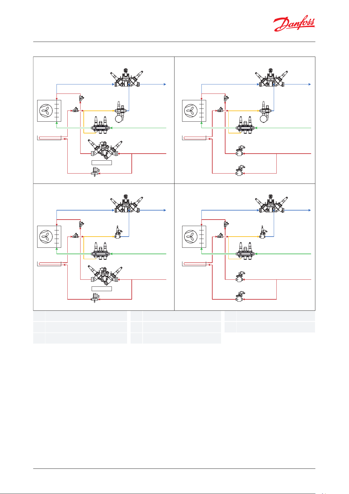
ABCDEFG
H
Soft-opening
CHV
CHV
EVRST
ICSH
ICLX
ICF
ICFE
ICFSICFR
ICFF
ICFC
ICFW
ICFD
ICF
ICFS
ICFE
ICFS
CHV
CHV
ICS
ICLX
EVM
ICF
ICFE
ICFSICFR
ICFF
ICFC
ICFW
ICF
ICFS
ICFS
ICFE
ICFD
ICS
EVM
Soft-opening
CHV
CHV
EVRST
ICSH
ICLX
EVM
CVP
ICS
ICF
ICFE
ICFSICFR
ICFF
ICFC
ICFW
CHV
CHV
ICS
ICLX
EVM
ICF
I
CFE
ICFSICFR
ICFF
ICFC
ICFW
EVM
CVP
ICS
ICS
EVM
A
B B
B B
C C
C C
A
D D
D D
A A
E E
E E
F F
F F
G G
G G
H H
H H
Danfoss
80G8136
Soft opening
Evaporator
Drip tray
Wet return line
Defrost drain line
Liquid feed line
Hot gas defrost line
Drip tray line
Evaporator and room control, type EKE 400
Figure 2: Flowchart
© Danfoss | Climate Solutions | 2021.03
AI306444073210en-000801 | 4
Page 5
Danfoss
80G8231
Evaporator and room control, type EKE 400
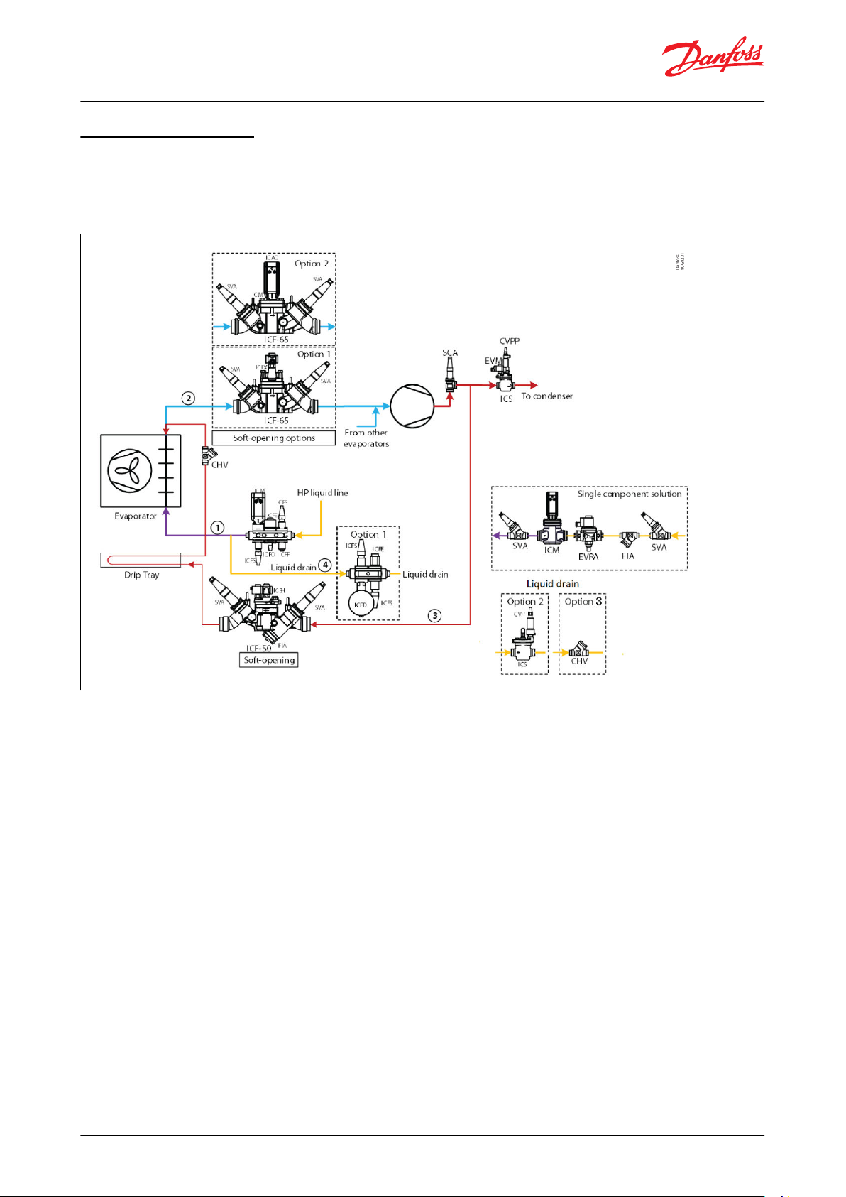
DX and Hot gas defrost
X and Hot gas defrost
D
EKE 400 oers the possibility to control DX applications and combine with Hot gas defrost across all the possible
valves available. E.g. EKE 400 can support DX and CO2, combined with Hot gas defrost with ICF valve stations.
Figure 3: Application sketch
© Danfoss | Climate Solutions | 2021.03 AI306444073210en-000801 | 5
Page 6
Evaporator and room control, type EKE 400
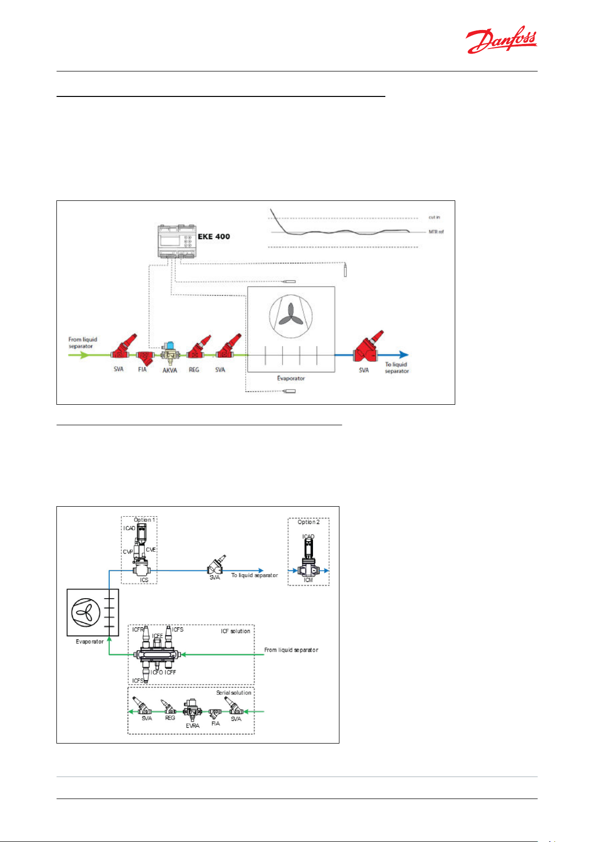
MTR (Modulating TheRmostat) in Liquid Line Flooded systems
TR (Modulating TheRmostat) in Liquid Line Flooded systems
M
As for DX systems, EKE 400 has an adapted function of MTR also for ooded systems. Selecting this function, EKE 400
wil be able to control the room temperature much more accurate than a traditional ON/OFF temperature control.
EKE 400 will also equalize the load on the system to get better operating conditions. MTR requires PWM (Pulse
Width Modulating) valves like Danfoss type AKV or AKVA in the liquid line. Typical industrial applications with the
refrigerant Ammonia or CO2 is in scope.
Figure 4: MTR in Liquid line ooded systems
Media temperature and pressure control - suction line
M
edia temperature and pressure control - suction line
EKE 400 will be able to control valves in the wet suction return line. The control mode can be either temperature or
pressure. Support of Danfoss Industrial Refrigeration Valves like ICM with ICAD and ICS/CVE/ICAD can be combined
with multiple defrost methods, including Hot Gas.
Figure 5: Media temperature and pressure control - suction line
(7)
7
Same basic media temperature functions as in EKC 361, but with updated and optimized algorithm. See A
© Danfoss | Climate Solutions | 2021.03
ppendix C
AI306444073210en-000801 | 6
Page 7
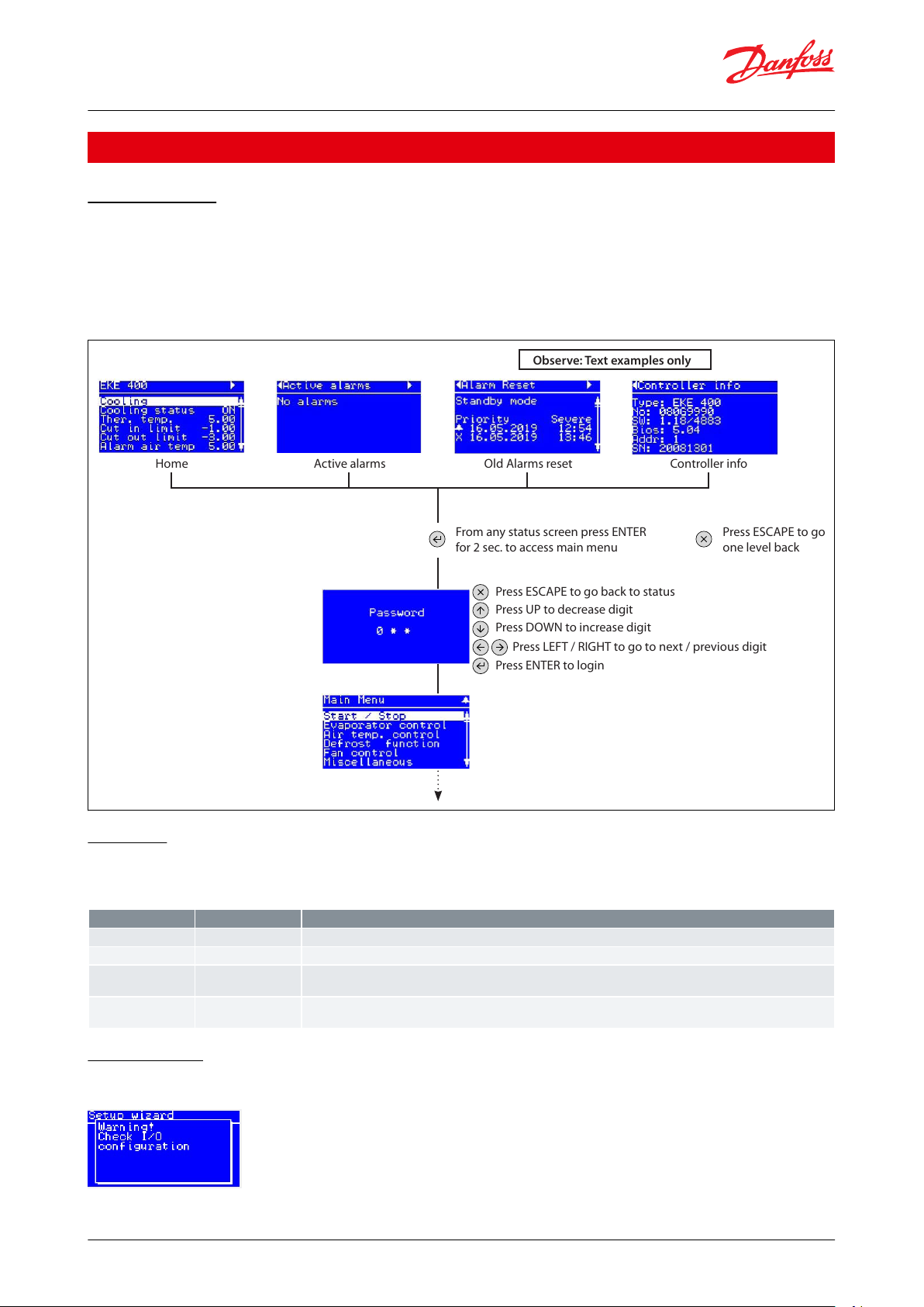
Home Active alarms Old Alarms reset
Observe: Text examples only
Controller info
From any status screen press ENTER
f
or 2 sec. to access main menu
Press ESCAPE to go back to status
Press UP to decrease digit
Press DOWN to increase digit
Press ENTER to login
Press LEFT / RIGHT to go to next / previous digit
Press ESCAPE to go
one lev
el back
Parameter
Password level
Functions
Password level 0
Level 0 will only allow to see the screens: "Status screen 1", "Active alarms", "Alarm Reset" and "Controller info"
G07
Password level 1
Level 1 will give access to see all parameters and sub menus, but no settings can be changed.
G08
Password level 2
Enter password for level 2 access. Level 1 will give access to see all parameters and sub menus. Some settings can
changed
.
G09
Password level 3
Enter password for level 3 access. Level 1 will give access to see all parameters and sub menus. All settings can
changed
.
Evaporator and room control, type EKE 400
Product specication
Basic operation
asic operation: Conguration and daily operation of EKE 400 is done via the built-in HMI or via a remote
B
connected HMI. The display supports multiple languages and engineering units.
Status screens: Get an overview of how the system is running in the status screens. Use the LEFT / RIGHT buttons to
view the status screens.
Figure 6: Status screen
Password
ee EKE 400 Wizard, Parameterlist, for further details further details on Password levels and user rights
S
Table 1: Password level
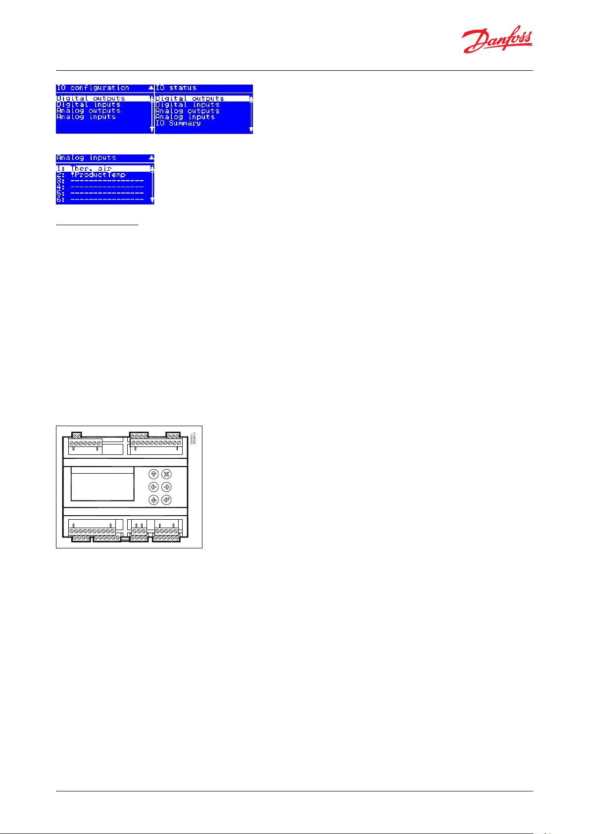
Conguration
f the I/O conguration can not be met, after the Wizard is completed, a warning will be displayed
I
Go to IO c
onguration or IO status and go through Digital output/input and Analog output/input
© Danfoss | Climate Solutions | 2021.03
AI306444073210en-000801 | 7
Page 8
Danfoss
80G8010
Evaporator and room control, type EKE 400
Identify the IO with and exclamation mark “!” and recongure it.
Setup overview
T
here are two ways in which the controller can be set up:
Wizard
• Here you will be led through a series of selected parameters that are commonly needed to be c
start up. This will also mean faster setup for many applications.
• Please observe, that some parameters not included in the Wizard may still need to be congured. this must then
be done from the complete Parameter list
Parameter list
• Here a complete list of all parameters can be found
ongured at every
perating principles:
O
1.
Select position using arrow keys
2.
Select using “Enter”
3.
Use the “X” to return
Figure 7: EKE 400
© Danfoss | Climate Solutions | 2021.03
AI306444073210en-000801 | 8
Page 9
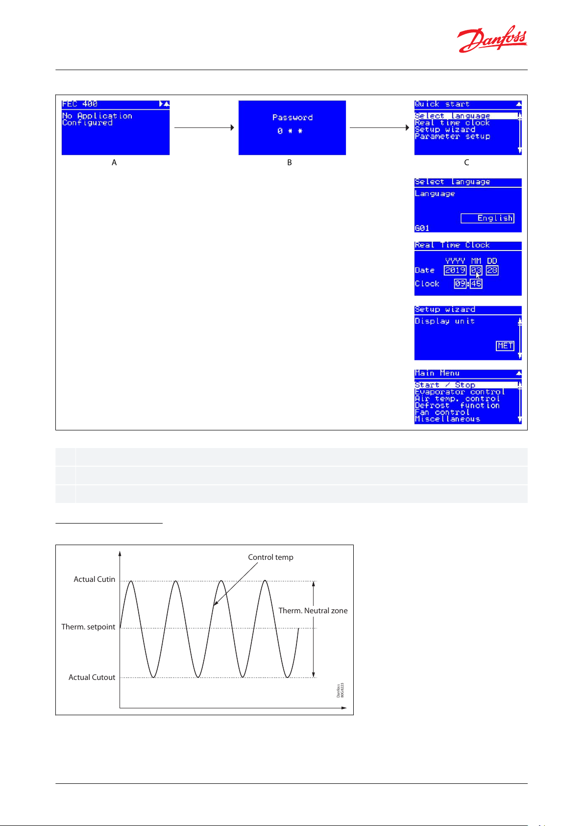
ABC
A B C
Hold “Enter” down for 2 seconds to come to password entry
The default password upon delivery is 300. Use the arrow keys to set the password. End by pressing “Enter”
Select a set-up method. End by pressing “Enter”
Danfoss
80G8223
Actual Cutout
Therm. setpoint
Actual Cutin
Control temp
Therm. Neutral zone
Evaporator and room control, type EKE 400
Figure 8: Start screen upon delivery
Temperature control
F
igure 9: Temperature control
For ON/OFF thermostat and F
looded and DX application
One, two or three temperatures sensors, normally located in the cool room, can be connected to EKE 400. The
number of sensors depends normally on the size of the room.
© Danfoss | Climate Solutions | 2021.03
AI306444073210en-000801 | 9
Page 10
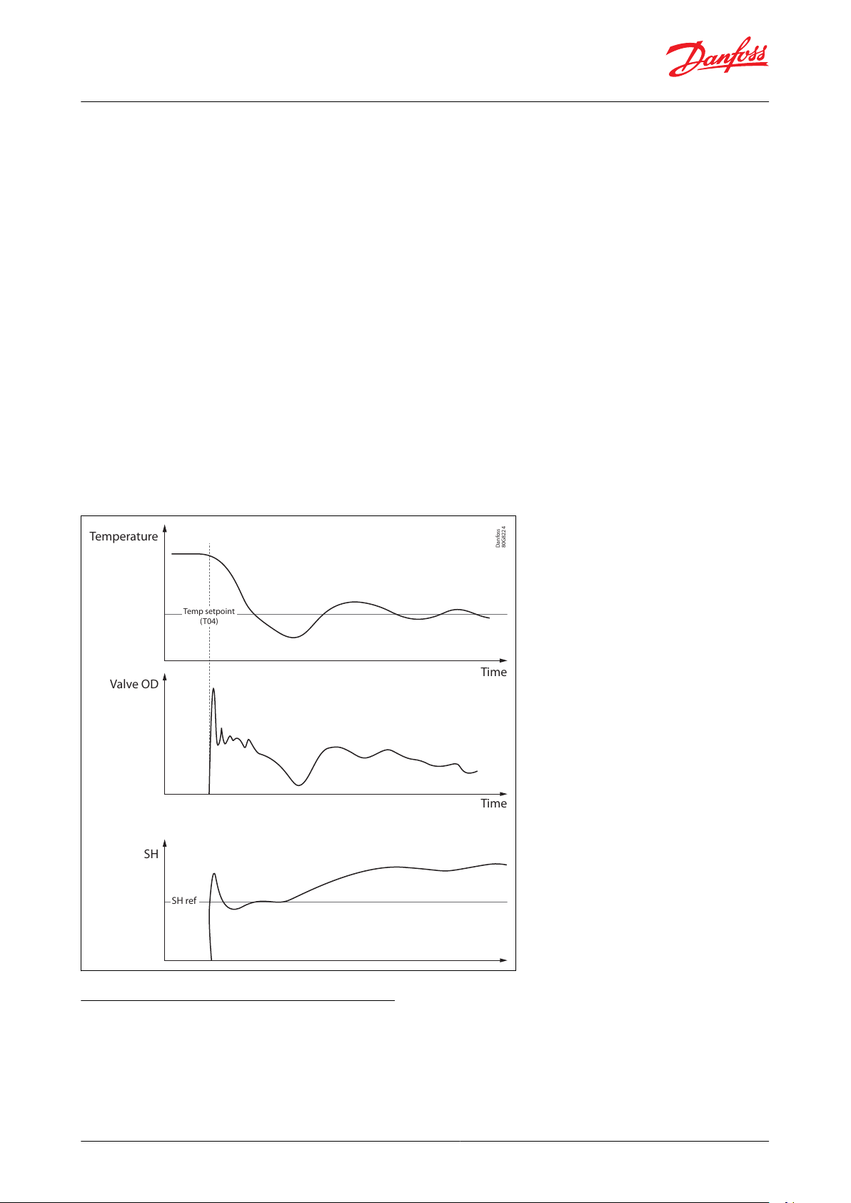
Temperature
Valve OD
SH
Time
Time
Temp setpoint
(T04)
SH ref
Danfoss
80G8224
Evaporator and room control, type EKE 400
If more than one temperature sensor have been selected, then the thermostat function can be selected to control
emperature from the average or the highest temperature from the temperature sensors.
t
A Temperature setpoint (T04) and a Neutral zone(T05) are entered in EKE 400. Neutral zone divided by 2 will give
Cut-in and Cut-out temperature of the thermostat, normally the liquid line valve ON/OFF.
Modulating thermostat (MTR)
DX only
Observe: The MTR function must not be enabled in a system containing only 1 evaporator
Modulating thermostat (MTR regulation maintains a more constant temperature and also equalize the load on the
system to get better operating conditions:
• Each of the individual evaporator sections is controlled individually using a modulating thermostat function.
• A Temperature setpoint (T04) and a Neutral zone(T05) must be set as with an ON/OFF thermostat.
TR is modulating the cooling capacity to match the cooling demand.
M
In the pull-down phase then the temperature is well above the MTR set point cooling capacity is at maximum and
superheat is controlled to be on superheat reference. When temperature is getting close to the MTR reference
(typical 4 K) the cooling capacity gradually reduce so that the temperature can be stable on the MTR reference.
The MTR reference is dened by Temperature setpoint (T04).
Figure 10: Modulating thermostat
Superheat reference calculation methods
n superheat mode the controller will control the superheat to be stable and closer to the superheat reference. This
I
will give the optimal utilization of heat exchanger and thereby maximum cooling capacity. If superheat is too low,
the ow in the expansion is decreased and superheat will be higher.
© Danfoss | Climate Solutions | 2021.03
AI306444073210en-000801 | 10
Page 11
Danfoss
80G8225
TT
P
S2
TT, S2
P
Pt1000 temperature sensor
Pressure transmitter
Danfoss
80G8226
EKE
oper
ating
envelope
Pressure (P)
Enthalpy (H)
Superheat
r
eference
Evaporator and room control, type EKE 400
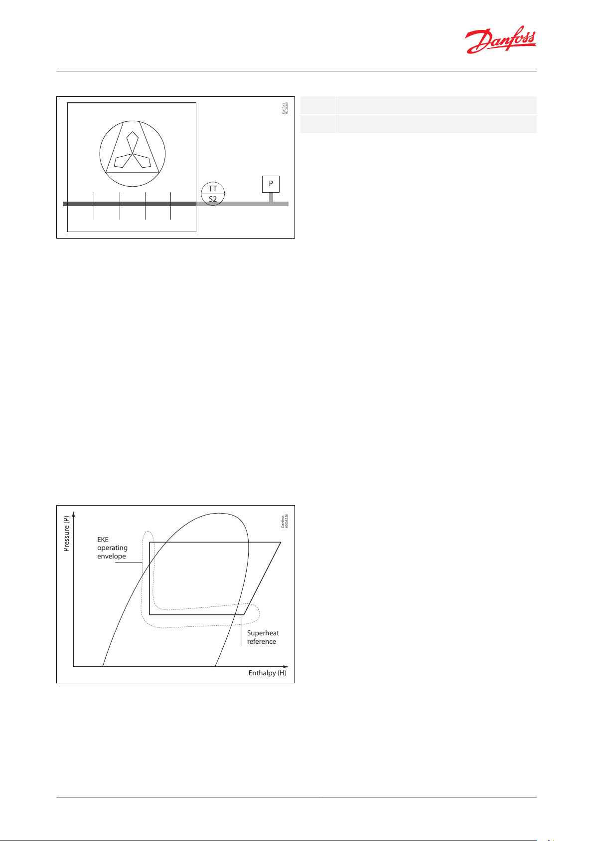
Figure 11: Actual superheat = S2 - T0
P can be display
ed in [Bar] or [psi].
It a refrigerant has been entered in parameter “r20,Refrigerant“ then the calculated evaporating temperature,
converted from the pressure transmitter, is called T0 (or Te).
Superheat reference can be calculated based on following 3 dierent methods:
MSS (Minimum Stable Superheat)
The superheat control algorithm will attempt to regulate the superheat down to the lowest stable value between
the minimum superheat setting, “Min SH” and the maximum superheat setting, “Max. SH”.
LoadAP Superheat
LoadAP is an abbreviation of “load dened reference”. LoadAP will adjust reference to be higher if load is higher.
Load is indicated by the OD of valve. LoadAP is a kind of preprogrammed MSS curve. This method will give a robust
SH reference and can in many cases be the best t for systems.
Fixed Superheat
This feature is used in a system where a stable xed superheat is required.
• MSS - Parameter N01, SH ref. mode is set to: Adaptive SH ctrl
• LoadAP - Parameter N01, SH ref. mode is set to: Load dened c
trl
• Fixed Superheat - Parameter N01, SH ref. mode is set to: Fixed SH ref.
Figure 12: Superheat reference
© Danfoss | Climate Solutions | 2021.03
AI306444073210en-000801 | 11
Page 12
Danfoss
84B1488
100 %
Qo
Unstable r
e
g
ion
(wet)
10 %
Superheat
Danfoss MSS
Danfoss LoadAP
Fixed SH, 3rd party SH control
Danfoss
84B1487
100 %
10 %
40 %
Superheat
Q o
Un
stable r
egion
(wet)
Stable
r
egion (dry)
Min. SH Max. SH
Danfoss MSS
Evaporator and room control, type EKE 400
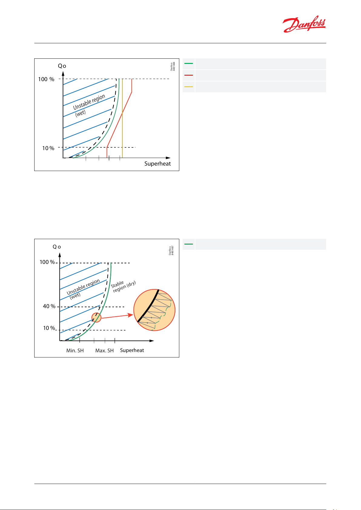
Figure 13: Comparison between SH reference
MSS
he controller will search for the minimum stable superheat between an upper and lower boundary. If the
T
superheat has been stable for a period, the superheat reference is decreased. If the superheat becomes unstable.
the reference is raised again. This process continues as long as the superheat is within the bounds set by the user.
The purpose of this is to search for the lowest possible superheat that can be obtained while still maintaining a
stable system.
Figure 14: MSS
MSS PI controller is made up of 3 parts:
• a stability set point
• the variant from the Te signal
• actual superheat reference
T
he stability set point is given from the “user”. The variants from the T0 signal is used to allow for increased
instability if the T0 signal is unstable. Finally the part from the actual superheat allows for more instability at higher
superheat references than at lower references.
The superheat reference SH ref is adaptive and adjusted. When using this form of control, there are three settings
that have major eect on this mode of control. These are Min. SH, Max. SH and SH close parameters.
© Danfoss | Climate Solutions | 2021.03
AI306444073210en-000801 | 12
Page 13
Danfoss
80G8227
Start time
Min start
time
The Pctrl is active in
the min star
t time and
until SH cross the
reference
SH
SH ref
Danfoss
80G8228
Start time
Min start
time
The Pctrl is active until
the star
t time if SH
does not get below
reference
SH
SH ref
Parameter
Function
Description
R01
Evaparator control mode
2 = DX control
N01
SH reference mode
2 = Adaptive SH ctrl.
N03
SH max. value
Max. allowed SH reference
N04
SH min. value
Min. allowed SH reference Note: SH min. value must be >0.5K higher than SH close value, if N09 =
1
N18
MSS stability
Stablility factor for regulation of superheat, only relevant for MSS. With a higher value the control
func
tion will allow a greater uctuation of the superheat before the reference is changed.
N19
MSS T0 stability factor
Only relevant for MSS. T0 stability factor denes if v
ariation in suction pressure will inuence superheat reference. The SH reference change can be adjusted by setting the value 0 to 1 (1 = max
T0 inuence and S2, 0 = S2 only). With often change in suction pressure due to compressor start/
stop, some T0 (and S2) inuence on MSS is recommended.
N09
SH close function
0 = O
| 1 = On, default = 1
N10
SH close setpoint
Default value = 2 K (recommended)
Evaporator and room control, type EKE 400
Where to use:
MSS is a benet f
or systems with a long runtime and slow changing conditions like cold rooms, display cases and
chillers. Short cycling and system with fast changing operation condition will not benet from MSS as this feature
will take time to nd the optimal reference. Adaption to a new set point is approx. 15 min.
Table 2: Functions
Start up
ometimes in one to one applications. the valve does not open suciently on start-up and troublesome low-
S
pressure trips happen. The following features allows the valve to open faster as well as to reach the optimal
operating conditions quickly.
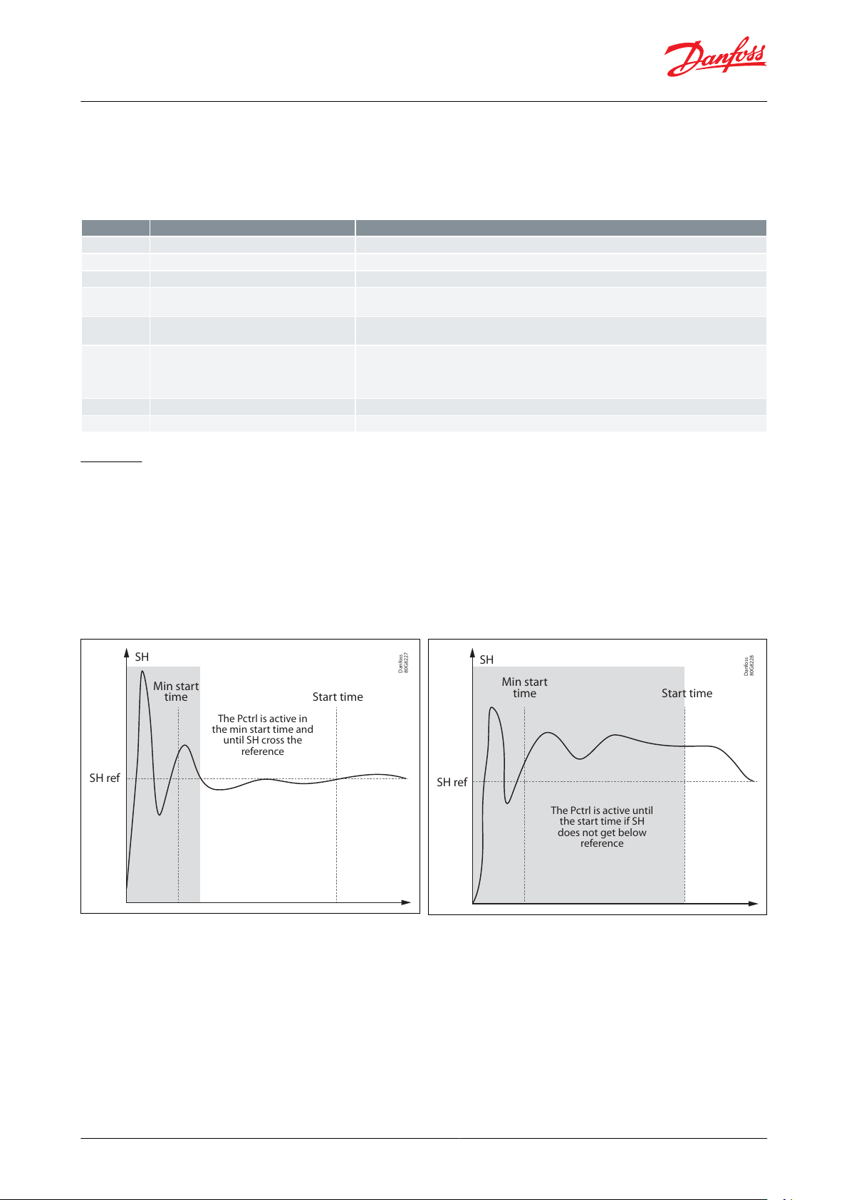
Proportional (P) control N20, Startup Mode=0
P-control function quickly stabilize the system's superheat by reaching optimal operating conditions in shorter
period of time. The controller is programmed for auto proportional control that will quickly change the opening
degree based on evaporating temperature and superheat of the system.
Figure 15: SH reference
Figure 16: SH reference
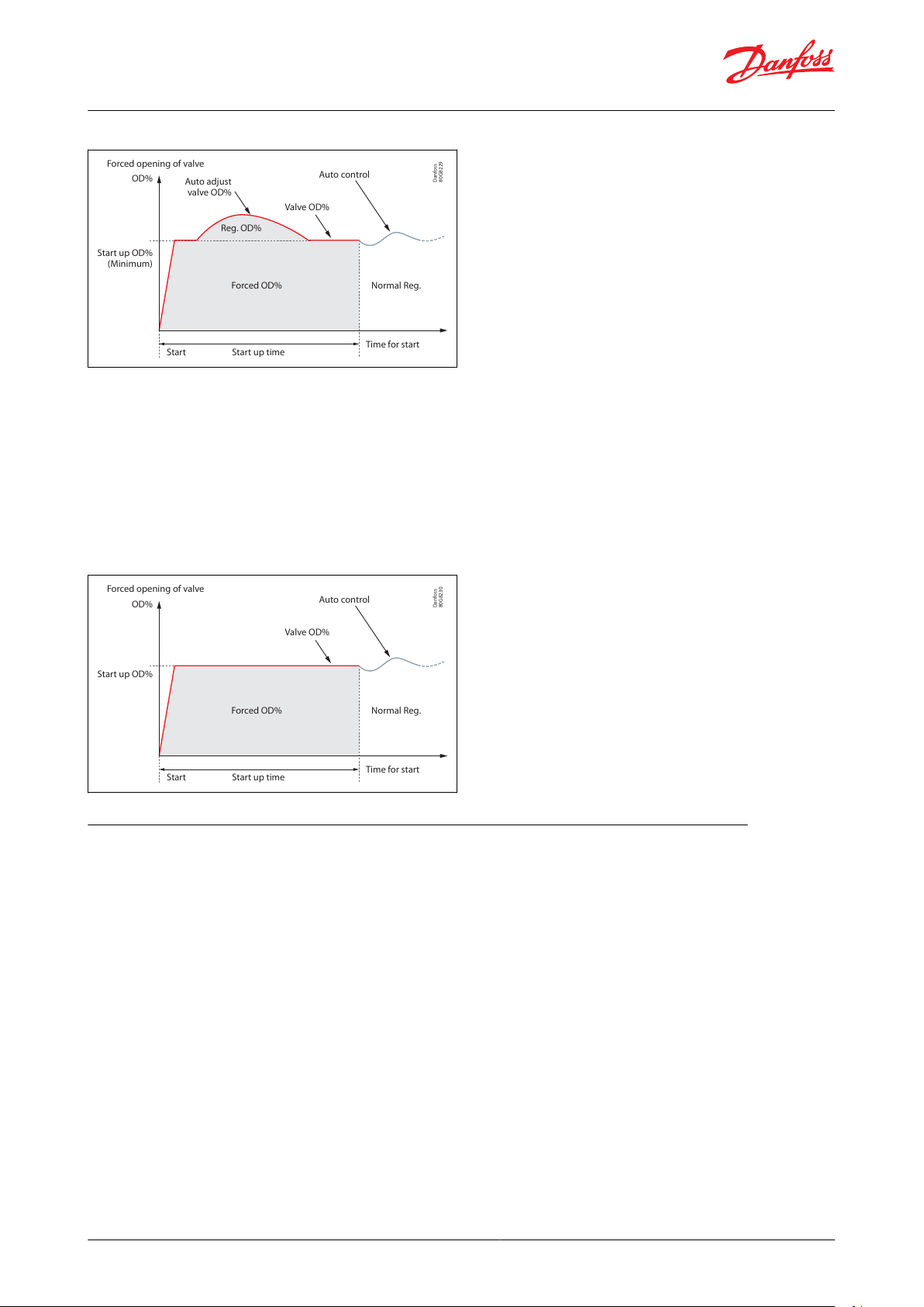
Predened OD with protection N20, Startup Mode=1
After startup, this function will provide a start opening degree during a set time period. If the limiters, the valve will
do the auto adjustment based on the operating conditions and the set limitations.
© Danfoss | Climate Solutions | 2021.03
AI306444073210en-000801 | 13
Page 14
Danfoss
80G8229
Auto control
Forced opening of valve
Auto adjust
v
alve OD%
Valve OD%
Reg. OD%
Forced OD% Normal Reg.
Time for start
Start up time
Start up OD%
(M
inimum)
OD%
Start
Danfoss
80G8230
Auto control
Forced opening of valve
Valve OD%
Forced OD% Normal Reg.
Time for start
Start up time
Start up OD%
OD%
Start
Evaporator and room control, type EKE 400
Figure 17: P
redened OD with protection N20
NOTE:
A
t start up. if the valve is opened too much, it could result in ow of liquid in the compressor or could trigger the HP
switch which will stop the system. Whereas if you start the system with too low opening degree. it could also stop
the system because of the low-pressure switch cut in. It will be safe to start the system with approximately 50% OD
of the valve at start up, if P-control is not being used.
Predened OD without protection N20, Startup Mode=2
After startup, this function will provide a constant opening degree during a set time period regardless of the
superheat value. No limiters are taken in consideration during this time.
Figure 18: Predened OD without protection N20
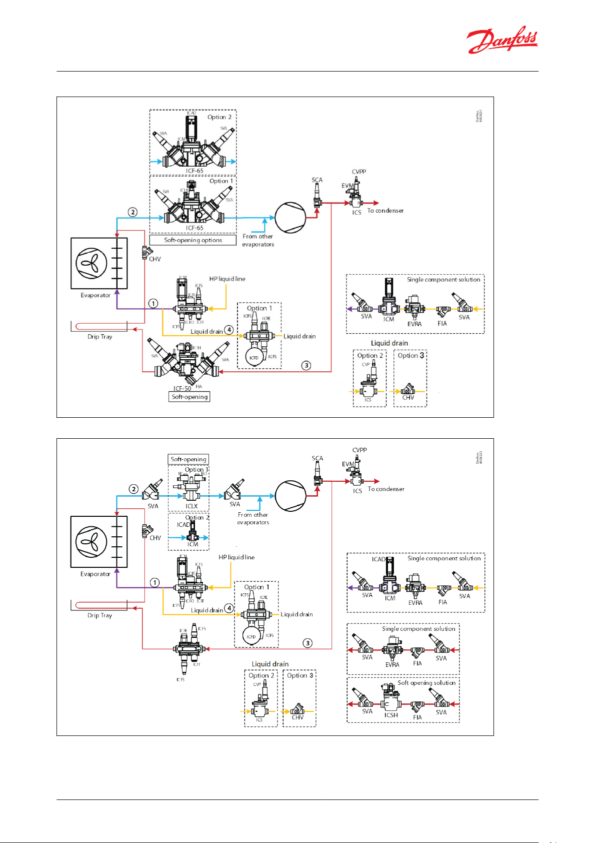
DX with defrost by Hot Gas, and the Defrost Drain Line connected to the receiver
n a DX application, with Hot Gas defrost and the Defrost Drain Line connected to the receiver, the EKE 400 can
I
provide a function to manage the valve in the main Hot Gas line. See Figure 19 and Figure 20.
If the Defrost Drain Line is connected to the Liquid receiver it is possible to control the valve in the main HG line
from EKE 400. The purpose of the valve in the main Hot Gas line (e.g. Danfoss type ICS with EVM (SI-port) and a CVPP
(P-port)) is to build up pressure in the Hot Gas line to the receiver during defrost. I.e. once the EVM is energized then
pressure is built up in the Hot Gas line to the receiver via the CVPP.
The EVM can be controlled from the EKE 400. See sketch below: The parameter: D08, Def. seq. status on DO, must be
set to: Yes The assigned DO (DO1 to DO8) must be connected to the EVM on the ICS with CVPP in the main Hot Gas
line.
© Danfoss | Climate Solutions | 2021.03
AI306444073210en-000801 | 14
Page 15
Danfoss
80G8231
Danfoss
80G8232
Evaporator and room control, type EKE 400
Figure 19: Application sketch
Figure 20: Application sketch
© Danfoss | Climate Solutions | 2021.03 AI306444073210en-000801 | 15
Page 16

Label ID
(1)
Parameter name
Description and selection options
Min.
Max.
Factory setting
QS
Select quick setting
Select most common type of applications
S
electing one of below application will then preselect valves the actual appliction
in question. See Table 2
1: Flooded On/O: Flooded, Thermostat ON/FF with Hotgas Defrost by pressure
or Liquid drain
2: Dx On/O: DX with Hotgas Defrost by pressure or Liquid drain
3: Flooded Mod WR ctrl: Flooded, Wet Return line control (pressure) Defrost by
pressure or Liquid drain
5: PWM mod.ood: PWM Modulating Thermostat (MTR) in Liquid Line. Flooded
systems
6: EKC315A replace: Retrot/upgrade from EKC 315A to EKE 400
7: EKC361 replace: Retrot/upgrade from EKC 361 to EKE 400
0: User dened; Means that if none of the applications 1 to 7, match - then select
User dened and continue to complete the wizard
070
P01
Display unit
Display unit
0:ME
T: Metric units - Celsius (°C) and Kelvin (°K)
1:IMP: Imperial units - Fahrenheit (°F) and Rankine (°R)
010=MET
R01
Evap. ctrl mode
Evaporator control mode:
-1:None
0:F
lood. evap. On/O
2: DX control
-120=Flood. evap. On/O
D1A
Defrost method
Select the defrost method
0: No defr
ost: No defrost function
1: Hot gas: Defrost done by Hot gas
2:Electrical, water or air defrost (air defrost in rooms with temperature higher
than 0 °C (32 °F))
021=Hot gas
T01
Ther. mode
Select thermostat control mode
1: I
ndividual On/O
3: Mod WR ctrl: MTC (Media Temperature Control) in Wet Return line
5: Pwm mod.ood.: Modulating Thermostat (MTR) in Liquid Line. Flooded systems
151=Individual On/O
R04
Mod WR ctrl. Mode
Select the mode for MTC (Media Temperature Control) in Wet Return line
0: T
emp room const.: Temperature control
1: Press.evap const. evap.: Pressure control
010=Temp room cons
R20
Refrigerant
Select Refrigerant
0: not used;1: R12;2: R22;3: R134a;4: R502;5: R717;6: R13;7: R13B1;8: R23;9:
R500;10: R503;11: R114;12: R142b;13: U
ser;14:R32;15:R227ea;16: R401A;17:
R507A;18: R402A;19: R404A;20: R407C;21: R407A;22: R407B;23: R410A;24: R170;25:
R290;26: R600;27: R600a;28: R744;29: R1270;30: R417A;31: R422A;32: R413A;33:
R422D;34: R427A;35: R438A;36: R513A;37: R407F;38: R1234zeE;39: R1234yf;40:
R448A;41: R449A;42: R452A;43: R450A;44: R452B;45: R454B;46:R1233zdE;47:
R1234zeZ;48: R449B;49: R407H;
0490=Not used
R2A
Liq. feed line valve
Select type of valves in Liquid feed line
1: S
olenoid (ICFE): ON/OFF Solenoid ICF 20 Valve station
2: Solenoid (ICS): ON/OFF Solenoid ICS with EVM pilot
3: Solenoid (ICM): Motorized ICM, as slow opening/closing ON/OF valve. Occupy 1
DO
131=Solenoid (ICFE)
R2B
Liq. feed line valve DX
Select Liquid feed line valve for DX
4: AK
V: AKV or AKVA. Occupy 1 DO. DO5 or DO6 must be assigned
5: AKV + Solenoid: AKV or AKVA (Occupy 1 DO. DO5 or DO6 must be assigned) +
Solenoid (Occupy 1 DO)
6: Mod ICM; Modulating motorized ICM. Occupy 1 AO
7: Mod ICM + solenoid: Modulating motorized ICM (Occupy 1 AO) + Solenoid
(Occupy 1 DO)
474=AKV
R2C
Liq. feed line valve
PWM
Select Liquid feed line valve for Modulating Thermostat (MTR) Flooded
sy
stems
4: AKV: AKV or AKVA. Occupy 1 DO. DO5 or DO6 must be assigned
5: AKV + Solenoid: AKV or AKVA (Occupy 1 DO. DO5 or DO6 must be assigned) +
Solenoid (Occupy 1 DO)
454=AKV
Evaporator and room control, type EKE 400
EKE 400 Wizard
Table 3: EKE 400 Wizard
© Danfoss | Climate Solutions | 2021.03
AI306444073210en-000801 | 16
Page 17

Label ID
(1)
Parameter name
Description and selection options
Min.
Max.
Factory setting
D3A
Wet return line val.
Select type of valves in Wet return suction line
0: No V
alve
1: Soft (ICS+EVRST): Dual position individual solenoid valves. Occupy 2 DO
2: Soft (ICSH): Dual position solenoid valve. Occupy 2 DO
3: Soft (ICLX): 2-step gas powered solenoid valve. Occupy 1 DO
4: Solenoid (ICS):ON/OFF Solenoid ICS with EVM pilot
5: Solenoid (ICM):Motorized ICM, as slow opening/closing ON/OF valve. Occupy 1
DO
6: Slow (ICM): Motorized ICM, as slow opening/closing modulating valve. Occupy
1 AO
063=Soft (ICLX)
D3C
Wet return line val.
Select type of valves in Wet return line
7: M
od (ICM): Modulating Motorized ICM
8: Mod+PE (ICM+EVRST): Modulating Motorized ICM with pressure Equalization
valve EVRA/EVRAT/EVRST
787=Mod (ICM)
D2A
Hot gas line valve
Select type of valves in Hot gas defrost line
0: No V
alve
1: Soft (ICS+EVRST): Dual position individual solenoid valves. Occupy 2 DO
2: Soft (ICSH): Dual position solenoid valve. Occupy 2 DO
3: Solenoid (ICFE): ON/OFF Solenoid ICF 20 Valve station
4: Solenoid (ICS):ON/OFF Solenoid ICS with EVM pilot
5: Solenoid (ICM):Motorized ICM, as slow opening/closing ON/OF valve. Occupy 1
DO
6: Slow (ICM): Motorized ICM, as slow opening/closing modulating valve. Occupy
1 AO
062=Soft (ICSH)
D1B
HG Drain valve
Select type of valves in defrost drain line
0: P
ressure (ICS+CVP): Pressure control valve during hot gas defrost. CVP pilot
have adjustable pressure setting
1: Pressure (OFV): Pressure control valve during hot gas defrost. OFV have
adjustable pressure setting
2: Liquid drain (ICFD): Liquid drain during defrost
021=Pressure (ICS+CVP)
D2B
HG Drip tray DO
Select possible DO hot gas valve for drip tray line
No: No Dr
ip tray valve/function
Yes: Drip tray valve and function active
0=No
Yes=1
0=No
D4A
Drain solenoid?
Decide if drain solenoid in defrost drain line is installed
No
Y
es
0=No
1=Yes
1=Yes
D4B
Quick Drain?
Decide if drain valve is installed to drain liquid quikly out before hot gas
en
ter evaporator
No
Yes
0=No
1=Yes
0=No
T04
Ther. setpoint
Thermostat set point temperature
-50.0
50.0
2.0
T05
Ther. neutral zone
Thermostat neutral zone
S
tart/Stop limit around the "T03 Ther. Setpoint"
0.1
20.0
2.0
T17
Suc.Pres. SP To
Evaporator pressure Setpoint in [C] / [F]
T
emperature Setpoint in [C]/[F] compared measured pressure value (calulated
into [C]/[F]
-50.0
50.0
0.0
B02
High alarm limit
High alarm limit
H
igh alarm for the room temperature alarm function. Entered as absolute value
-50.0
50.0
6.0
B03
Low alarm limit
Low alarm limit
L
ow alarm for the room temperature alarm function. Entered as absolute value
-50.0
50.0
-30.0
B04
Alarm delay
Alarm delay
A
larm delay time during normal control used for both high- and low temperature
alarms
0
240
120
D11
Def. time interval
Defrost start by time interval
F
ail safe function if another congured defrost start, has failed.
A defrost will be started when the interval counter (real time) exceeds the
‘Defrost time interval’ setting.
The interval counter is start counting from zero when the defrost is started.
The interval counter will be reset at every defrost start.
The interval counter shall be in standby (not counting) at "Main switch is OFF".
Can be seen in Status Sceen 1.
If "D11,Def. time interval" is 0 (zero) the function is disabled
0
240
0
Evaporator and room control, type EKE 400
© Danfoss | Climate Solutions | 2021.03 AI306444073210en-000801 | 17
Page 18

Label ID
(1)
Parameter name
Description and selection options
Min.
Max.
Factory setting
D12
Def. start acc. cool
time
Defrost start by accumulated cooling time
C
an also be used as a fail safe function if another congured defrost start, has
failed.
A defrost will be started when the accumulated cooling time exceeds "D12,Def.
start acc. cool time" setting.
The accumulated cooling time will be reset at every defrost start.
0
240
0
D14
Def. start by DI
Defrost start by DI
Option t
o start defrost via DI. Typical external dignal from PLC or a push bottom.
If function is enabled, a defrost is started when the DI changes from OFF to ON.
Successive change of the DI during the defrost period are ignored.
No: Function disable
Yes: Function enabled"
0=No
1=Yes
0=No
D15
Def. start schedule
Defrost start schedule
Option t
o run defrost according to local time scedules in EKE 400. Three
schcdules possible (weekdays, saturdays and sunday) with 6 defrost start time
each
No: Function disable
Yes:Function enabled"
0=No
1=Yes
0=No
D40
Defrost stop method
Defrost stop method
S
elect method for stop of defrost
1: Stop on time: When the time delay "D58,Max defrost time" expires, the defrost
is terminated
2: Stop on temp: When the defrost sensor temperature becomes greater than the
set point "D43,Def. stop temp. limit", then the defrost is terminated. If the defrost
time exceed "D58,Max defrost time", then the alarm ‘Max defrost time’ is send and
the defrost is terminated. In case of sensor error, and the time ‘Max defrost time’
expires, the alarm ‘Max defrost time’ is send and the defrost is terminated. The
alarm will automatically be reset after 5 minutes.
To assign defrost sensor temperature, go to I/O conguration in Main menu and
select an available AI"
121=Stop on time
D43
Def. stop temp. limit
Defrost stop temperature limit
S
ee description for "D40, Defrost stop method"
0.0
25.0
8.0
D50
Pump down delay
Pump down delay
Dr
aining the evaporator before defrosting.
Always active
The pump down state is used to empty the evaporator for liquid.
See Figure 21: Defrost sequence.
13010
D51
HG open delay
Hot Gas open delay
T
ime delay in minutes before opening the hot gas valve (delay for valve in the
wet return line to close)
See Figure 21: Defrost sequence.
1105
D5A
Drip tray pre-heat
Driptray pre-heat
P
re-heating time for hot gas to drip tray
See Figure 21: Defrost sequence
0205
D5B
Drip tray delay OFF
Drip tray delay OFF
C
ontinue drip tray heating some dened time
See Figure 21: Defrost sequence
0
120
30
D57
Quick drain time
Quick drain time
En
ter how long time the Quick Drain valve stays open. Quick Drain valve will start
opening together with Hot gas valve
See Figure 21: Defrost sequence
1
300
30
D53
HG soft time
Hot gas soft time
T
ime between step 1 and step 2 for opening the hot gas valve (2 DO used)
See Figure 21: Defrost sequence.
1303
D58
Max defrost time
Max defrost time
M
ax. allowed defrost duration in minutes
1
120
30
D59
Drip o time
Drip o time
A
llow water on the evaporator to drip o.
See Figure 21: Defrost sequence.
1155
D61
WR soft time
Wet return soft time
T
ime between step 1 and step 2 for opening the wet return valve ("Soft (ICS
+EVRST)" or "Soft (ICSH)
See Figure 21: Defrost sequence.
1302
Evaporator and room control, type EKE 400
© Danfoss | Climate Solutions | 2021.03
AI306444073210en-000801 | 18
Page 19

Label ID
(1)
Parameter name
Description and selection options
Min.
Max.
Factory setting
D6A
WR main time
Wet return main time
A
fter defrost and wet return valve has opened (main), enter delay before valve in
liquid line to open.
See Figure 21: Defrost sequence.
1302
D65
Fan start delay
Fan start delay
T
he fan will be started when the time has elapsed.
See Figure 21: Defrost sequence.
0302
D69
WR Pr. Equalising
WR Pressure Equalizing time
E
qualizing pressure in evaporator by soft opening wet return line valve. Carefully
emptying the evaporator for hot gas via a little drain valve (by-pass valve) in the
wet return line or soft opening of wet return valve.
1105
P03
Main switch via DI
Mainswitch via DI
R
elease EKE 400 for operation or force EKE 400 out of operation via external
equipment (e.g. PLC), via DI
OFF: EKE 400 is forced out of operation. Observe if "M01,Main switch" is ON, this
parameter will also when OFF, force EKE 400 out of operation
ON: EKE 400 released for operation. Observe if "M01,Main switch" is ON, this
parameter must also be ON, to release EKE 400 for operation
0=No
1=Yes
0=No
Label
ID
(1)
Parameter
name
Description and selection options
Min.
Max
Factory
S
etting
Dec‐
im‐
als
Locked
b
y Main
switch
Yes/No
Read
Pass‐
w
ord
level to
change/
write
Modbus
addr
ess
Read
only
(R
O) /
Read
Write
(RW)
Persis‐
t
ent
Yes/No
Modbus
func
tion
M01
Main switch
Release the controller for operation or
f
orce EKE 400 out of operation
OFF: the controller is forced out of
operation. Observe if "M02, Ext. Main
switch" is ON, this DI will also when OFF,
forced the controller out of operation
ON: the controller released for operation.
Observe if "M02, Ext. Main switch" is ON,
this DI must also be ON to release the
controller for operation
0=OFF
1=ON
0=OFF0No
Passw
ord
level
1,2,3
2
3001RWYes
3, 4 & 16
M02
Ext. Main
swit
ch
Status of the external main switch (DI)
0=OFF
1=ON-0
Yes
Passw
ord
level
1,2,3
Can nev-
er be
changed
3002ROYes
3
Evaporator and room control, type EKE 400
(1)
(1)
Visibility depends on other parameter settings. Numbers are displayed in Metric units ( P01, Temperature units=MET)
Visibility depends on other parameter settings. Numbers are displayed in Metric units ( P01, Temperature units=MET)
Parameter list
ve that many of the individual parameters listed below, will only be visible, if other parameters have been set.
Obser
Hereby irrelevant parameters are ltered out, during setup of EKE 400.
NOTE:
See Label ID, G07, G08, G09.
1.
All Modbus parameters is type: WORD (signed 16 bit).
2.
Start / Stop
Table 4: Start / Stop
(1)
(1)
Visibility depends on other parameter settings. Numbers are displayed in Metric units ( P01, Temperature units=MET).
Visibility depends on other parameter settings. Numbers are displayed in Metric units ( P01, Temperature units=MET).
© Danfoss | Climate Solutions | 2021.03 AI306444073210en-000801 | 19
Page 20

Label
ID
(1)
Parameter
name
Description and selection options
Min.
Max
Factory
S
etting
Dec‐
im‐
als
Locked
b
y Main
switch
Yes/No
Read
Pass‐
w
ord
level to
change/
write
Modbus
addr
ess
Read
only
(R
O) /
Read
Write
(RW)
Persis‐
t
ent
Yes/No
Modbus
func
tion
R01
Evap. ctrl
mode
Evaporator control mode:
-1: None
0: F
lood. evap. ON/OFF
-100=Flood.
ev
ap.
On/O;
0
Yes
Passw
ord
level
1,2,3
3
3020RWYes
3, 4 & 16
R2A
Liq. feed
line v
alve
Select Liquid feed line valve
1: S
olenoid (ICFE): ON/OFF Solenoid ICF
20 Valve station
2: Solenoid (ICS): ON/OFF Solenoid ICS
with EVM pilot
3: Solenoid (ICM): Motorized ICM, as
ON/OF valve. Occupy 1 DO
1310Yes
Passw
ord
level
1,2,3
3
3021RWYes
3, 4 & 16
R2B
Liq. feed
line v
alve
for DX
Select Liquid feed line valve for DX
4: AK
V: AKV or AKVA. Occupy 1 DO. DO5
or DO6 must be assigned
5: AKV + Solenoid: AKV or AKVA (Occupy
1 DO. DO5 or DO6 must be assigned) +
Solenoid (Occupy 1 DO)
6: Mod ICM; Modulating motorized ICM.
Occupy 1 AO
7: Mod ICM + solenoid: Modulating
motorized ICM (Occupy 1 AO) + Solenoid
(Occupy 1 DO)
4740Yes
3384RWYes
R2C
Liq. feed
line v
alve
PWM
Select Liquid feed line valve for
M
odulating Thermostat (MTR)
Flooded systems
4: AKV: AKV or AKVA. Occupy 1 DO. DO5
or DO6 must be assigned
5: AKV + Solenoid: AKV or AKVA (Occupy
1 DO. DO5 or DO6 must be assigned) +
Solenoid (Occupy 1 DO)
4540Yes
3380RWYes
R10
LL valve AI
f
eedback
Liquid Line feedback from ICAD on
ICM v
alve
In IO conguration \ Analog inputs the
Analog input type can be selected. 0-10
V;0-20 mA;4-20 mA;2-10 V
No: ICAD not connected to EKE 400
Yes: ICAD connected to EKE 400
No
YesNo0
Yes
Passw
ord
level
1,2,3
3
3446RWYes
3, 4 & 16
R05
Cool On/O
by DI
Cooling demand from external
equipmen
t (e.g. PLC) to EKE 400, via DI
0=No
1=Yes
0=No0Yes
Passw
ord
level
1,2,3
3
3024RWYes
3, 4 & 16
R06
Forced closing
Forced stop cooling via MODBUS (e.g.
PL
C) or local from EKE 400
If a PLC controls cooling ON/OFF,
"R06,Forced closing" can be used to stop
cooling
OFF: Function disabled
ON: Forced stop cooling, regardless of
cooling request. Observe. Will
automatically after 15 min go back to
OFF
0=OFF
1=ON
0=OFF0No
Passw
ord
level
1,2,3
2
3025RWNo
3, 4 & 16
Evaporator and room control, type EKE 400
Evaporator control \ Evaporator control mode
Table 5: Evaporator control \ Evaporator control mode
© Danfoss | Climate Solutions | 2021.03
AI306444073210en-000801 | 20
Page 21

Label
ID
(1)
Parameter
name
Description and selection options
Min.
Max
Factory
S
etting
Dec‐
im‐
als
Locked
b
y Main
switch
Yes/No
Read
Pass‐
w
ord
level to
change/
write
Modbus
addr
ess
Read
only
(R
O) /
Read
Write
(RW)
Persis‐
t
ent
Yes/No
Modbus
func
tion
R07
Forced
c
ooling
Forced cooling via MODBUS (e.g. PLC)
or lo
cal from EKE 400
The function is typical used to secure
enough hot gas to defrost other
evaporators If a PLC controls cooling ON/
OFF, "R07,Forced cooling" can be used to
start cooling
OFF: Function disabled
ON: Forced cooling, regardless of cooling
request. Observe. Will automatically after
15 min go back to OFF
0=OFF
1=ON
0=OFF0No
Passw
ord
level
1,2,3
2
3026RWNo
3, 4 & 16
R08
Forced
close b
y DI
Forced stop cooling via external
equipmen
t (e.g. PLC) to EKE 400, via DI
If a PLC controls cooling ON/OFF, DI can
be used to stop cooling
No: Function disabled
Yes: Forced stop cooling, regardless of
cooling request. To assign DI, go to I/O
conguration in Main menu and select
an available DI
0=No
1=Yes
0=No0Yes
Passw
ord
level
1,2,3
3
3027RWYes
3, 4 & 16
R09
Forced cool
b
y DI
Forced cooling via external equipment
(e
.g. PLC) to EKE 400, via DI
If a PLC controls cooling ON/OFF, DI can
be used to start cooling
No: Function disabled
Yes: Forced cooling, regardless of cooling
request. To assign DI, go to I/O
conguration in Main menu and select
an available DI
0=No
1=Yes
0=No0Yes
Passw
ord
level
1,2,3
3
3028RWYes
3, 4 & 16
Evaporator and room control, type EKE 400
(1)
(1)
Visibility depends on other parameter settings. Numbers are displayed in Metric units ( P01, Temperature units=MET).
Visibility depends on other parameter settings. Numbers are displayed in Metric units ( P01, Temperature units=MET).
© Danfoss | Climate Solutions | 2021.03 AI306444073210en-000801 | 21
Page 22

Label
ID
(1)
Parameter
name
Description and selection options
Min.
Max
Factory
S
etting
Dec‐
im‐
als
Locked
b
y Main
switch
Yes/No
Read
Pass‐
w
ord
level to
change/
write
Modbus
addr
ess
Read
only
(R
O) /
Read
Write
(RW)
Persis‐
t
ent
Yes/No
Modbus
func‐
tion
R20
Refrigerant
Select Refrigerant
0: not used;1: R12;2: R22;3: R134a;4: et
c.
0: not used;1: R12;2: R22;3: R134a;4:
R502;5: R717;6: R13;7: R13B1;8: R23;9:
R500;10: R503;11: R114;12: R142b;13:
User;14:R32;15:R227ea;16: R401A;17:
R507A;18: R402A;19: R404A;20:
R407C;21: R407A;22: R407B;23:
R410A;24: R170;25: R290;26: R600;27:
R600a;28: R744;29: R1270;30: R417A;31:
R422A;32: R413A;33: R422D;34:
R427A;35: R438A;36: R513A;37:
R407F;38: R1234zeE;39: R1234yf;40:
R448A;41: R449A;42: R452A;43:
R450A;44: R452B;45:
R454B;46:R1233zdE;47: R1234zeZ;48:
R449B;49: R407H
04900Yes
Passw
ord
level
1,2,3
3
3029RWYes
3, 4 & 16
R23
Refrig fact.
A1
User dened r
efrigerant
When R20=13 (User dened refrigerant)
Enter the Refrigerant factor A1
constants for the Antoine Equation for
the actual refrigerant
8000
13000
104003Yes
3032RWYes
R24
Refrig fact.
A2
User dened r
efrigerant
When R20=13 (User dened refrigerant)
Enter the Refrigerant factor A2
constants for the Antoine Equation for
the actual refrigerant
-3200.0
-1200.0
-2255.01Yes
3033RWYes
R25
Refrig fact.
A3
User dened r
efrigerant
When R20=13 (User dened refrigerant)
Enter the Refrigerant factor A3
constants for the Antoine Equation for
the actual refrigerant
220.0
320.0
254.21Yes
3034RWYes
Evaporator and room control, type EKE 400
Evaporator control \ Pressure c
onguration
Table 6: Evaporator control \ Pressure conguration
(1)
(1)
Visibility depends on other parameter settings. Numbers are displayed in Metric units ( P01, Temperature units=MET).
Visibility depends on other parameter settings. Numbers are displayed in Metric units ( P01, Temperature units=MET).
© Danfoss | Climate Solutions | 2021.03
AI306444073210en-000801 | 22
Page 23

Label
ID
(1)
Parameter
name
Description and selection options
Min.
Max
Factory
S
etting
Dec‐
im‐
als
Locked
b
y Main
switch
Yes/No
Read
Pass‐
w
ord
level to
change/
write
Modbus
addr
ess
Read
only
(R
O) /
Read
Write
(RW)
Persis‐
t
ent
Yes/No
Modbus
func
tion
N01
SH ref.
mode
Select Superheat reference mode:
0: F
ixed SH ref. Used when a stable xed
superheat is required
1: Load dened ctrl: LoadAp mode.
Reference set in dependence of actual
load (Opening Degree) Useful in
applications with rapidly changing load
conditions and at very short cut-in
perios.
2: Adaptive SH ctrl: MSS (Minimum Stable
Superheat) The superheat control
algorithm will constantly lower the
superheat reference, until some
instability is registrated
021= Load
dened
c
trl
0xPass-
w
ord
level
1,2,3
3
3003RWYes
3, 4 & 16
N02
SH Fixed
setpoin
t
Superheat x
ed setpoint
The superheat reference is xed to this
set point under all operating conditions
0.5
40.0
8.01Pass-
w
ord
level
1,2,3
3
3004RWYes
3, 4 & 16
N03
SH max
Superheat maximum
M
aximum limitation of superheat
reference
0.5
40.0
10.01No
Passw
ord
level
1,2,3
2
3005RWYes
3, 4 & 16
N04
SH min
Superheat minimum
M
inimum limitation of superheat
reference
Unit: °C / °F
0.5
10.0
4.01No
Passw
ord
level
1,2,3
2
3006RWYes
3, 4 & 16
N05
SH Tn
Superheat Integration time
I
ntegration time (Tn) in PI controller
Unit: °C / °F
20
900900NoPass-
w
ord
level
1,2,3
3
3007RWYes
3, 4 & 16
N06
SH Kp min
Superheat minimum Proportional gain
c
onstant
Minimum proportional gain in Superheat
PI controller
Unit: °C / °F
0.1
1.0
0.61No
Passw
ord
level
1,2,3
3
3008RWYes
3, 4 & 16
N07
SH Kp
Superheat Proportional gain constant
P
roportional gain in Superheat PI
controller
Unit: sec
0.1
20.0
1.51No
Passw
ord
level
1,2,3
3
3009RWYes
3, 4 & 16
N08
SH KpTe
Superheat Pressure feedback gain
P
roportional gain constant on saturated
temperature
0
20.0
3.01No
Passw
ord
level
1,2,3
3
3010RWYes
3, 4 & 16
N09
SH close
func
tion
Superheat close function
No: F
untion Disabled
Yes: Function Enabled
0=No
1=Yes
1=Yes0Yes
Passw
ord
level
1,2,3
2
3011RWYes
3, 4 & 16
N10
SH close
setpoin
t
Superheat close limit
I
f the superheat is below this value the
valve in the liquid line is forced to close
-5.0
20.0
2.01No
Passw
ord
level
1,2,3
3
3012RWYes
3, 4 & 16
N11
SH close Tn
divide
Advanced parameter setting
F
or Danfoss only
1530No
Passw
ord
level
1,2,3
3
3013RWYes
3, 4 & 16
N12
SH close Kp
fac
tor
Advanced parameter setting
F
or Danfoss only
Unit: °C / °F
0.5101.50No
Passw
ord
level
1,2,3
3
3014RWYes
3, 4 & 16
Evaporator and room control, type EKE 400
Evaporator control mode \ Evaporator DX control
Table 7: Evaporator control mode \ Evaporator DX control
© Danfoss | Climate Solutions | 2021.03 AI306444073210en-000801 | 23
Page 24

Label
ID
(1)
Parameter
name
Description and selection options
Min.
Max
Factory
S
etting
Dec‐
im‐
als
Locked
b
y Main
switch
Yes/No
Read
Pass‐
w
ord
level to
change/
write
Modbus
addr
ess
Read
only
(R
O) /
Read
Write
(RW)
Persis‐
t
ent
Yes/No
Modbus
func
tion
N13
MOP function
Maximum Operating Pressure
MOPfunc
tion will limit the valve opening
degree such that the saturated
evaporation temperature Te is kept
below the "N14,MOP" set point. MOP
prevents overloading the compressor
during start-up, by reducing suction
pressure
No: Funtion Disabled
Yes: Function Enabled
No
Yes
0=No0Yes
Passw
ord
level
1,2,3
2
3015RWYes
3, 4 & 16
N14
MOP setpoin
t
Maximum Operating Pressure setpoint
A
ctive if "N13, MOP function" is set to Yes
The actual MOP Evaporator pressure
Setpoint in [C] / [F]
-70.0
50.0
0.01No
Passw
ord
level
1,2,3
2
3016RWYes
3, 4 & 16
N15
MTR Tn
Advanced parameter
I
ntegration time for the MTR algorithm
20
3600
18000No
Passw
ord
level
1,2,3
3
3017RWYes
3, 4 & 16
N16
MTR Kp
Advanced parameter
P
roportional factor for the MTR algorithm
Unit: °C / °F
20
3600
18000No
Passw
ord
level
1,2,3
3
3018RWYes
3, 4 & 16
N17
AKV period
AKV or AKVA period time
P
eriod time of AKV or AKVA
Example: "N17, AKV Period" is set to 6
sec., the Opening Degree is calculated to
40 %, then AKV or AKVA is open in 2,4
sec., and closed in 3, 6 sec
3660Yes
Passw
ord
level
1,2,3
2
3019RWYes
3, 4 & 16
N18
MSS stabilit
y
Minimum Stable Superheat stability
S
tability factor for regulation of
superheat, only relevant for MSS. With a
higher value the control function will
allow a greater uctuation of the
superheat before the reference is
changed.
0.0
10.0
5.01Yes
Passw
ord
level
1,2,3
3
3397RWYes
N19
MSS T0 stabilit
y factor
Minimum Stable Superheat stability
T0 fac
tor
Only relevant for MSS. T0 stability factor
denes if variation in suction pressure
will inuence superheat reference. The
SH reference change can be adjusted in
the range frome 0.0 to 1.0
A value of 1.0 will give max T0 inuence
and S2.
A value of 0.0 will give inuence on S2
only.
With often change in suction pressure
due to compressor start/stop, some T0
(and S2) inuence on MSS is
recommended.
0.0
1.0
0.01Yes
Passw
ord
level
1,2,3
3
3390RWYes
N20
Startup
M
ode
Startup Mode (See section Start Up)
A
fter startup, this function will provide a
constant opening degree during a set
time period regardless of the superheat
value. No limiters are taken in
consideration during this time.
0: Prop.Ctrl: Proprotional (P) control
1: Fix OD w prot: Predened OD
(parameter "N23, Startup OD") with
protection
2: Fix OD wo prot: Predened OD
(parameter "N23, Startup OD") without
protection
0200Yes
Passw
ord
level
1,2,3
3
3393RWYes
Evaporator and room control, type EKE 400
© Danfoss | Climate Solutions | 2021.03
AI306444073210en-000801 | 24
Page 25

Label
ID
(1)
Parameter
name
Description and selection options
Min.
Max
Factory
S
etting
Dec‐
im‐
als
Locked
b
y Main
switch
Yes/No
Read
Pass‐
w
ord
level to
change/
write
Modbus
addr
ess
Read
only
(R
O) /
Read
Write
(RW)
Persis‐
t
ent
Yes/No
Modbus
func
tion
N21
Startup
time
"Startup time (See section Start Up)
T
his parameter is related to "N20, Startup
Mode"
Unit: sec
1
600900
Yes
Passw
ord
level
1,2,3
3
3394RWYes
N22
Min.startup
time
Min.startup time (See section Start Up)
T
his parameter is related to "N20, Startup
Mode"
Unit: sec
1
240150
Yes
Passw
ord
level
1,2,3
3
3395RWYes
N23
Startup OD
Startup Opening Degree (See section
S
tart Up)
This parameter is related to "N20, Startup
Mode"
Unit: %
1
100320
Yes
Passw
ord
level
1,2,3
3
3396RWYes
N24
Minimum
OD
Minimum Opening Degree
W
hen required, the valve minimum OD
can be set to a required minimum
opening position, such feature is helpful
where the system always requires some
minimum ow.
The minimum OD limit has eect in
injection control mode only
Unit: %
0
10000
Yes
Passw
ord
level
1,2,3
3
3398RWYes
N25
Maximum
OD
Maximum Opening Degree
T
his is useful feature to limit the
maximum OD of a oversized valve used
in the system.
By default the maximum OD of a valve is
set at 100 OD%. This maximum OD % can
be set to lower value if required.
The maximum OD limit has eect in
injection control mode only
Unit: %
0
100
1000Yes
Passw
ord
level
1,2,3
3
3399RWYes
N26
Limit Kp
Limit Kp - Superheat c
onguration
Advance
Proportional gain
1.0
20.0
5.01Yes
Passw
ord
level
1,2,3
3
3400RWYes
N27
Limit Tn
Limit Tn - Superheat c
onguration
Advance
Integration time
Unit: sec
20
900450
Yes
Passw
ord
level
1,2,3
3
3401RWYes
N36
S3 air
in.t
emp.AI?
Air temperature sensor (S3) installed?
U
sed for MTR
0: No not installed
1: Yes installed
To assign AI, go to I/O conguration in
Main menu and select an available AI
0100Yes
Passw
ord
level
1,2,3
3
3405RWYes
Evaporator and room control, type EKE 400
© Danfoss | Climate Solutions | 2021.03 AI306444073210en-000801 | 25
Page 26

Label
ID
(1)
Parameter
name
Description and selection options
Min.
Max
Factory
S
etting
Dec‐
im‐
als
Locked
b
y Main
switch
Yes/No
Read
Pass‐
w
ord
level to
change/
write
Modbus
addr
ess
Read
only
(R
O) /
Read
Write
(RW)
Persis‐
t
ent
Yes/No
Modbus
func
tion
N28
Ext.Ref.DX
c
ong
External reference DX c
onguration
Select the signal used to change the
Superheat reference.
0: Not used
1: Displace by current: - dene the AI
input range via the following settings:
“N31,Ref.Current SH High”: 4 to 20 mA,
default = 20
“N32,Ref.Current SH Low”: 0 to 20 mA,
default = 4
To assign AI, go to I/O conguration in
Main menu and select an available AO
2: Displace by voltage: - dene the AI
input range via the following settings:
“N33,Ref.Voltage SH High”: 0 to10 Volt,
default = 10
“N34,Ref.Voltage SH Low”: 0 to 10 Volt,
default = 0
To assign AI, go to I/O conguration in
Main menu and select an available AI.
3: Displace by MODBUS
4: Displace by DI
0400Yes
Passw
ord
level
1,2,3
3
3402RWYes
N29
Ref.Oset
SH M
ax
Reference oset Sup
erheat maximum
Scaling of range for superheat
displacement - Maximum value.
See "N28, Ext.Ref.DX cong"
Unit: K
0.0
50.0
0.01No
Passw
ord
level
1,2,3
3
3410RWYes
N30
Ref.Oset
SH M
in
Reference oset Sup
erheat minimum
Scaling of range for temperature
displacement - Minimum value See "N28,
Ext.Ref.DX cong"
Unit: K
-50.0
0.0
0.01No
Passw
ord
level
1,2,3
3
3409RWYes
N31
Ref.Current
SH H
igh
Reference current Superheat high
S
caling of range for AI current - high
value See "N28, Ext.Ref.DX cong"
Unit: mA
N32
20.0
20.01No
Passw
ord
level
1,2,3
3
3354RWYes
N32
Ref.Current
SH L
ow
Reference current Superheat low Scaling
of r
ange for AI current - low value See
"N28, Ext.Ref.DX cong" Unit: mA
0.0
N31
4.01No
Passw
ord
level
1,2,3
3
3355RWYes
N33
Ref.Voltage
SH H
igh
Reference voltage Superheat high
S
caling of range for AI voltage - high
value See "N28, Ext.Ref.DX cong"
Unit: V
N34
10.0
10.01No
Passw
ord
level
1,2,3
3
3356RWYes
N34
Ref.Voltage
SH L
ow
Reference voltage Superheat low
S
caling of range for AI voltage - low value
See "N28, Ext.Ref.DX cong"
Unit: V
0.0
N33
0.01No
Passw
ord
level
1,2,3
3
3357RWYes
N35
Re.Oset
SH M
odbus
Reference oset Sup
erheat by
MODBUS
Oset value via MODBUS (e.g. PLC)
added to current SH reference.
Unit: K
-50.0
50.0
0.01No
Passw
ord
level
1,2,3
3
3358RWYes
N38
Ref. O
set
SH by DI
Reference O
set Superheat when DI is
open, 0 K if closed
If P10, Ext ref. cong.=Displace by DI,
then if the assigned DI:
OFF: No oset added
ON: Value entered here will be added to
SuperHeat reference
Unit: K
-70.0
50.0
0.01No
Passw
ord
level
1,2,3
3
3470RWYes
3, 4 & 16
N37
Tn SH tracking
Tn SH tracking
Unit: sec
3
600
2000No
Passw
ord
level
1,2,3
3
3413RWYes
Evaporator and room control, type EKE 400
© Danfoss | Climate Solutions | 2021.03
AI306444073210en-000801 | 26
Page 27

Label ID
(1)
Parameter name
Description and selection
options
Min.
Max
Factory
S
etting
Deci‐
mals
Locked
b
y
Main
switch
Yes/No
Read
Password
le
vel to
change/
write
Mod‐
bus ad‐
dr
ess
Read
only
(R
O) /
Read
Write
(RW)
Persis‐
t
ent
Yes/No
Mod‐
bus
func‐
tion
R2A
Liq. feed line valve
Select type of valves in
Liquid f
eed line
1:Solenoid (ICFE): ON/OFF
Solenoid ICF 20 Valve
station
2:Solenoid (ICS): ON/OFF
Solenoid ICS with EVM pilot
3:Solenoid (ICM): Motorized
ICM, as slow opening/
closing ON/OF valve.
Occupy 1 DO
1310Yes
Passw
ord
level
1,2,3
3
3021RWYes
3, 4 &
16
R2B
Liq. feed line valve
f
or DX
Select Liquid feed line
v
alve for DX
4: AKV: AKV or AKVA.
Occupy 1 DO. DO5 or DO6
must be assigned
5: AKV + Solenoid: AKV or
AKVA (Occupy 1 DO. DO5 or
DO6 must be assigned) +
Solenoid (Occupy 1 DO)
6: Mod ICM; Modulating
motorized ICM. Occupy 1
AO
7: Mod ICM + solenoid:
Modulating motorized ICM
(Occupy 1 AO) + Solenoid
(Occupy 1 DO)
4740Yes
Passw
ord
level
1,2,3
3
3384RWYes
3, 4 &
16
R2C
Liq. feed line valve
PWM
Select Liquid feed line
v
alve for Modulating
Thermostat (MTR)
Flooded systems
4: AKV: AKV or AKVA.
Occupy 1 DO. DO5 or DO6
must be assigned
5: AKV + Solenoid: AKV or
AKVA (Occupy 1 DO. DO5 or
DO6 must be assigned) +
Solenoid (Occupy 1 DO)
4540Yes
Passw
ord
level
1,2,3
3
3380RWYes
3, 4 &
16
D3A
Wet Return line val.
Select type of valves in
W
et return suction line
0: No Valve
1: Soft (ICS+EVRST): Dual
position individual solenoid
valves. Occupy 2 DO
2: Soft (ICSH): Dual position
solenoid valve. Occupy 2
DO
3: Soft (ICLX): 2-step gas
powered solenoid valve.
Occupy 1 DO
4: Solenoid (ICS):ON/OFF
Solenoid ICS with EVM pilot
5: Solenoid (ICM):Motorized
ICM, as slow opening/
closing ON/OF valve.
Occupy 1 DO
6: Slow (ICM): Motorized
ICM, as slow opening/
closing modulating valve.
Occupy 1 AO
0630Yes
Passw
ord
level
1,2,3
3
3253RWYes
3, 4 &
16
Evaporator and room control, type EKE 400
(1)
(1)
Visibility depends on other parameter settings. Numbers are displayed in Metric units ( P01, Temperature units=MET).
Visibility depends on other parameter settings. Numbers are displayed in Metric units ( P01, Temperature units=MET).
Evaporator control \ Valve c
onguration
Table 8: Evaporator control \ Valve conguration
© Danfoss | Climate Solutions | 2021.03 AI306444073210en-000801 | 27
Page 28

Label ID
(1)
Parameter name
Description and selection
options
Min.
Max
Factory
S
etting
Deci‐
mals
Locked
b
y
Main
switch
Yes/No
Read
Password
le
vel to
change/
write
Mod‐
bus ad‐
dr
ess
Read
only
(R
O) /
Read
Write
(RW)
Persis‐
t
ent
Yes/No
Mod‐
bus
func‐
tion
D03
Wet Return line val.
Select type of valves in
W
et return suction line
7: Mod (ICM): Modulating
motorized ICM. Occupy 1
AO
8: Mod+PE (ICM+EVRST):
Modulating motorized ICM,
occupy 1 AO and Solenoid
for pressure pressure
equalization at opening,
occupy 1 DO
9: Mod (CVE): Electronic
pressure pilot. Occupy 1 AO
10: Mod+PE (CVE+ EVRST):
Electronic pressure pilot.
Occupy 1 AO and Solenoid
for pressure pressure
equalization at opening,
occupy 1 DO
11: Mod+PE(CVE+EVM
+EVRST): Electronic
pressure pilot. Occupy 1 AO
and two solenoid , occupy 2
DO. When installed in a ICS
3 topcover. SI port: EVM, to
secure valve closed during
defrost. SII port:CVE. P port:
Blocked. EVRST: For
pressure pressure
equalization at opening
71170Yes
Passw
ord
level
1,2,3
3
3388RWYes
3, 4 &
16
Evaporator and room control, type EKE 400
© Danfoss | Climate Solutions | 2021.03
AI306444073210en-000801 | 28
Page 29

Label ID
(1)
Parameter name
Description and selection
options
Min.
Max
Factory
S
etting
Deci‐
mals
Locked
b
y
Main
switch
Yes/No
Read
Password
le
vel to
change/
write
Mod‐
bus ad‐
dr
ess
Read
only
(R
O) /
Read
Write
(RW)
Persis‐
t
ent
Yes/No
Mod‐
bus
func‐
tion
D2A
Hot gas line valve
Select type of valves in
H
ot gas defrost line
0: No Valve
1: Soft (ICS+EVRST): Dual
position individual solenoid
valves. Occupy 2 DO
2: Soft (ICSH): Dual position
solenoid valve. Occupy 2
DO
3: Solenoid (ICFE): ON/OFF
Solenoid ICF 20 Valve
station
4: Solenoid (ICS):ON/OFF
Solenoid ICS with EVM pilot
5: Solenoid (ICM):Motorized
ICM, as slow opening/
closing ON/OF valve.
Occupy 1 DO
6: Slow (ICM): Motorized
ICM, as slow opening/
closing modulating valve.
Occupy 1 AO
0620Yes
Passw
ord
level
1,2,3
3
3247RWYes
3, 4 &
16
D2C
HG valve AI feedback
Hotgas Line feedback
fr
om ICAD on ICM valve
In IO conguration \ Analog
inputs the Analog input
type can be selected. 0-10
V;0-20 mA;4-20 mA;2-10 V
No: ICAD not connected to
EKE 400
Yes: ICAD connected to EKE
400
No
YesNo0
Yes
Passw
ord
level
1,2,3
3
3451RWYes
3, 4 &
16
D1B
HG Drain valve
Select type of valves in
defr
ost drain line
0:Pressure (ICS+CVP):
Pressure control valve
during hot gas defrost. CVP
pilot have adjustable
pressure setting
1: Pressure (OFV): Pressure
control valve during hot gas
defrost. OFV have
adjustable pressure setting
2: Liquid drain (ICFD):
Liquid drain during defrost
0210Yes
Passw
ord
level
1,2,3
3
3245RWYes
3, 4 &
16
Evaporator and room control, type EKE 400
(1)
(1)
Visibility depends on other parameter settings. Numbers are displayed in Metric units ( P01, Temperature units=MET).
Visibility depends on other parameter settings. Numbers are displayed in Metric units ( P01, Temperature units=MET).
© Danfoss | Climate Solutions | 2021.03 AI306444073210en-000801 | 29
Page 30

Label
ID
(1)
Parameter
name
Description and selection options
Min.
Max
Factory
S
etting
Dec‐
im‐
als
Locked
b
y Main
switch
Yes/No
Read
Pass‐
w
ord
level to
change/
write
Modbus
addr
ess
Read
only
(R
O) /
Read
Write
(RW)
Persis‐
t
ent
Yes/No
Modbus
func
tion
T1A
Ther. mode
Select thermostat control mode
0: None
1: I
ndividual On/O
2: Common On/O
3: Mod WR ctrl: MTC (Media Temperature
Control) in Wet Return line
5: Pwm mod.ood.: Modulating
Thermostat (MTR) in Liquid Line. Flooded
systems
0510Yes
Passw
ord
level
1,2,3
3
3037RWYes
3, 4 & 16
T1B
Ther. mode
Select thermostat control mode
0: None
1: I
ndividual On/O
2: Common On/O 4: MTR: Modulating
Thermostat (MTR) in Liquid Line. Flooded
systems
0410Yes
Passw
ord
level
1,2,3
2
3386RWYes
3, 4 & 16
R04
Mod WR
c
trl. Mode
Select the mode for MTC (Media
T
emperature Control) in Wet Return
line
0: Temp room const.: Temperature
control
1: Press.evap const. evap.:Pressure
control
010
Yes
Passw
ord
level
1,2,3
3
3022RWYes
3, 4 & 16
T02
No. of ther.
sensor
Number of temperature sensors
c
onnected to EKE 400
It is possible to connect up to 3 room
thermostat sensors to the same
controller. Typically, only one thermostat
sensor is connected, but sometimes
more sensors are connected to avoid
“hot spots” in a room.
0: No thermostat sensor connected
1: One thermostat sensor connected
2: Two thermostat sensors connected
3: Three thermostat sensors connected
0310Yes
Passw
ord
level
1,2,3
2
3038RWYes
3, 4 & 16
T03
Ctrl temp.
method
Control method
T
he control method shall be selected if
common thermostat is selected or if
more thermostat sensors are connected
to EKE 400. The temperatures used of
thermostat is selected by setting of “T03,
Ctrl temp. method”:
0:Ctrl highest temp:
1:Ctrl average temp.:
0100Pass-
w
ord
level
1,2,3
2
3039RWYes
3, 4 & 16
T04
Ther. setpoin
t
Thermostat set point temperature
Unit: °C / °F
-70.0
50.0
2.01Pass-
w
ord
level
1,2,3
2
3040RWYes
3, 4 & 16
T05
Ther. neutr
al zone
Thermostat neutral zone
S
tart/Stop limit around the "T03 Ther.
Setpoint"
Unit: K
0.1
20.0
2.01Pass-
w
ord
level
1,2,3
2
3041RWYes
3, 4 & 16
T06
Day/night
c
ontrol
Day/Night control
F
unction that allow to add an oset value
to "T03 Ther. Setpoint"
No: Function disabled
Yes: Function enabled. Night status
visible in Status Screen 1
See "T08,Night oset"
No
YesNo0
Passw
ord
level
1,2,3
3
3042RWYes
3, 4 & 16
Evaporator and room control, type EKE 400
Air temperature control \ Thermostat function
Table 9: Air temperature control \ Thermostat function
© Danfoss | Climate Solutions | 2021.03
AI306444073210en-000801 | 30
Page 31

Label
ID
(1)
Parameter
name
Description and selection options
Min.
Max
Factory
S
etting
Dec‐
im‐
als
Locked
b
y Main
switch
Yes/No
Read
Pass‐
w
ord
level to
change/
write
Modbus
addr
ess
Read
only
(R
O) /
Read
Write
(RW)
Persis‐
t
ent
Yes/No
Modbus
func
tion
T07
Night operation
Night Operation
Enable func
tion to osett "T04,Ther.
Setpoint", typical via MODBUS (e.g. PLC)
No: Day operation : No oset - not active
Yes: Night operation. If "T06, Day/night
control" is Yes, then add "T08, Night
oset" to "T04,Ther. Setpoint"
No
YesNo0
Passw
ord
level
1,2,3
2
3043RWYes
3, 4 & 16
T08
Night oset
Night oset
En
ter the Oset value to thermostat set
point temperature. See "T07, Night
operation"
Unit: K
-20.0
20.0
-2.01No
Passw
ord
level
1,2,3
2
3044RWYes
3, 4 & 16
T09
Cool. status
DO
Cooling status DO
S
elect status if Evapartor is in cooling
mode and read out to Digital
OutputActual cooling status to be read
on a DO.
No:Funtion Disabled
Yes:Function Enabled. If Evapartor is in
cooling mode then DO is ON, otherwise
DO is OFF. To assign DO, go to I/O
conguration in Main menu and select
an available DO.
No
YesNo0
Yes
Passw
ord
level
1,2,3
3
3045RWYes
3, 4 & 16
T22
Min.Cooling OD
Minimum Cooling Opening Degree
limit
A limit can be dened t
o manage: - Text
in HMI: "Cooling Status" to display "OFF"
or "ON" - Cooling status DO, parameter
"T09, Cool. status DO", when set to "Yes"
If OD > ("T22,Min.Cooling OD" ) then
"Cooling Status" will display ON Assigned
DO related to "T09, Cool. status DO" is ON
If OD = 0% then "Cooling Status" will
display OFF Assigned DO related to "T09,
Cool. status DO" is OFF
Unit: %
02050Yes
Passw
ord
level
1,2,3
3
3437RWYes
3, 4 & 16
T10
Pwm
mod
.period
Modulating Thermostat (MTR) in
Liquid Line
. Flooded systems - period
time
Expert setting - The value should only be
changed by specially trained sta
Unit: sec
30
900
3000Yes
Passw
ord
level
1,2,3
3
3374RWYes
3, 4 & 16
T11
Pwm Max
OD
Modulating Thermostat (MTR) in
Liquid Line
. Flooded systems - Max OD
Maximum opening degree of the AKV or
AKVA in the liquid line
Unit: %
10
100
1000Yes
Passw
ord
level
1,2,3
3
3375RWYes
3, 4 & 16
T12
Pwm Min
OD
Modulating Thermostat (MTR) in
Liquid Line
. Flooded systems - Min OD
Minimum opening degree of the AKV or
AKVA in the liquid line
Unit: %
0
10000
Yes
Passw
ord
level
1,2,3
3
3376RWYes
3, 4 & 16
T13
Pwm Kp
Modulating Thermostat (MTR) in
Liquid Line
. Flooded systems -
Amplication factor
Expert setting - The value should only be
changed by specially trained sta
0.5
10.0
4.01Yes
Passw
ord
level
1,2,3
3
3377RWYes
3, 4 & 16
T14
Pwm Tn
Modulating Thermostat (MTR) in
Liquid Line
. Flooded systems -
Integration time
Expert setting - The value should only be
changed by specially trained sta
Unit: sec
60
1800
3000Yes
Passw
ord
level
1,2,3
3
3378RWYes
3, 4 & 16
Evaporator and room control, type EKE 400
© Danfoss | Climate Solutions | 2021.03 AI306444073210en-000801 | 31
Page 32

Label
ID
(1)
Parameter
name
Description and selection options
Min.
Max
Factory
S
etting
Dec‐
im‐
als
Locked
b
y Main
switch
Yes/No
Read
Pass‐
w
ord
level to
change/
write
Modbus
addr
ess
Read
only
(R
O) /
Read
Write
(RW)
Persis‐
t
ent
Yes/No
Modbus
func
tion
T15
Desynch.
P
wm
Desynchronization of Modulating
T
hermostat (MTR) in Liquid Line.
Flooded systems
Pwm duty to avoid simultaneousness
with other control
No
YesNo0
Yes
Passw
ord
level
1,2,3
3
3412RWYes
3, 4 & 16
T17
Suc.Pres. SP
T
o
Suction Evaporator Pressure Setpoint
in degr
ees
Setpoint coming from pressure
converted in temperature depending
from selected refrigerant
Unit: °C / °F
-50.0
50.001NoPass-
w
ord
level
1,2,3
2
3415RWYes
3, 4 & 16
T18
WR Kp
MTC (Media Temperature Control) in
W
et Return line - Kp
Proportional factor
0.5
50.0
3.01No
Passw
ord
level
1,2,3
3
3418RWYes
3, 4 & 16
T19
WR Tn
MTC (Media Temperature Control) in
W
et Return line - Tn
Integration time
Unit: sec
60
600
2400No
Passw
ord
level
1,2,3
3
3419RWYes
3, 4 & 16
T20
WR Td
MTC (Media Temperature Control) in
W
et Return line - Td
Dierential time
Unit: sec
060100No
Passw
ord
level
1,2,3
3
3420RWYes
3, 4 & 16
T21
Mod WR
c
trl. Mode
MTC (Media Temperature Control) in
W
et Return line - control mode
Select between:
0: Normal
1: Min underswing
2: No underswing
0220Yes
Passw
ord
level
1,2,3
3
3421RWYes
3, 4 & 16
Evaporator and room control, type EKE 400
(1)
(1)
Visibility depends on other parameter settings. Numbers are displayed in Metric units ( P01, Temperature units=MET).
Visibility depends on other parameter settings. Numbers are displayed in Metric units ( P01, Temperature units=MET).
© Danfoss | Climate Solutions | 2021.03
AI306444073210en-000801 | 32
Page 33

Label
ID
(1)
Parameter
name
Description and selection options
Min.
Max
Factory
S
etting
Dec‐
im‐
als
Locked
b
y Main
switch
Yes/No
Read
Pass‐
w
ord
level to
change/
write
Modbus
addr
ess
Read
only
(R
O) /
Read
Write
(RW)
Persis‐
t
ent
Yes/No
Modbus
func
tion
B01 /
B1B
Air temp.
alar
m
Select which temperature sensor shall
b
e connected to temperature alarms.
0:None: No temperature alarms active
1:Seperate sensor: A separate sensor for
the alarm function
2:Thermostat temp: The Thermostat
temperature sensot is used for the alarm
function
022=Ther-
mostat
t
emp.
0
Yes
Passw
ord
level
1,2,3
3
3046 /
3436
RW
Yes
3, 4 & 16
B02
High alarm
limit
High alarm limit
H
igh alarm for the room temperature
alarm function. Entered as absolute value
Unit: °C / °F
-70.0
50.0
6.01No
Passw
ord
level
1,2,3
2
3047RWYes
3, 4 & 16
B03
Low alarm
limit
Low alarm limit
L
ow alarm for the room temperature
alarm function. Entered as absolute
value.
Unit: °C / °F
-70.0
50.0
-30.01No
Passw
ord
level
1,2,3
2
3048RWYes
3, 4 & 16
B04
Alarm delay
Alarm delay
A
larm delay time during normal control
used for both high- and low temperature
alarms
Unit: min
0
240
1200No
Passw
ord
level
1,2,3
2
3049RWYes
3, 4 & 16
Evaporator and room control, type EKE 400
Air temperature control \ Air temp. Alarm
Table 10: Air temperature control \ Air temp. Alarm
(1)
(1)
Visibility depends on other parameter settings. Numbers are displayed in Metric units ( P01, Temperature units=MET).
Visibility depends on other parameter settings. Numbers are displayed in Metric units ( P01, Temperature units=MET).
© Danfoss | Climate Solutions | 2021.03 AI306444073210en-000801 | 33
Page 34

Label
ID
(1)
Parameter
name
Description and selection options
Min.
Max
Factory
S
etting
Dec‐
im‐
als
Locked
b
y Main
switch
Yes/No
Read
Pass‐
w
ord
level to
change/
write
Modbus
addr
ess
Read
only
(R
O) /
Read
Write
(RW)
Persis‐
t
ent
Yes/No
Modbus
func
tion
B05
Product
alar
m func-
tion
Product temperature alarm
T
he air temperature is not always
representative for the temperature of the
products. A product sensor to measure
the actual temperature in between the
products. This sensor is used for
monitoring purposes only including
alarm handling.
No: Function disabled
Yes: Function enabled. Product alarms
active.
"Product temp." can be seen in Status
Screen 1
0=No
1=Yes
0=No0Yes
Passw
ord
level
1,2,3
3
3050RWYes
3, 4 & 16
B06
Prod. high
alar
m limit
Product High alarm
H
igh alarm limit for the product
temperature alarm function. Entered as
absolute value
Unit: °C / °F
-70.0
50.0
6.01No
Passw
ord
level
1,2,3
2
3051RWYes
3, 4 & 16
B07
Prod. low
alar
m limit
Product Low alarm
L
ow alarm limit for the product
temperature
Unit: °C / °F
-70.0
50.0
-30.01No
Passw
ord
level
1,2,3
2
3052RWYes
3, 4 & 16
B08
Prod. alarm
delay
Product Alarm delay
A
larm delay time used for both high and
low product temperature alarm function
Unit: min
0
240
1200No
Passw
ord
level
1,2,3
2
3053RWYes
3, 4 & 16
Evaporator and room control, type EKE 400
Air temperature control \ Product temperature alarm function
Table 11: Air temperature control \ Product temperature alarm function
(1)
(1)
Visibility depends on other parameter settings. Numbers are displayed in Metric units ( P01, Temperature units=MET).
Visibility depends on other parameter settings. Numbers are displayed in Metric units ( P01, Temperature units=MET).
© Danfoss | Climate Solutions | 2021.03
AI306444073210en-000801 | 34
Page 35

Label
ID
(1)
Parameter
name
Description and selection options
Min.
Max
Factory
S
etting
Dec‐
im‐
als
Locked
b
y Main
switch
Yes/No
Read
Pass‐
w
ord
level to
change/
write
Modbus
addr
ess
Read
only
(R
O) /
Read
Write
(RW)
Persis‐
t
ent
Yes/No
Modbus
func
tion
D1A
Defrost
method
Select the defrost method
0:No defr
ost: No defrost function
1:Hot gas: Defrost done by Hot gas
If air defrost is (used in rooms with
temperature higher than 0° C (32 °F)
2:Electrical, water or air defrost (air
defrost in rooms with temperature
higher than 0° C (32 °F))
011=Hot
gas
0
Yes
Passw
ord
level
1,2,3
3
3244RWYes
3, 4 & 16
D1B
HG Drain
v
alve
Select type of valves in defrost drain
line
0: P
ressure (ICS+CVP): Pressure control
valve during hot gas defrost. CVP pilot
have ajustable pressure setting
1: Pressure (OFV): Pressure control valve
during hot gas defrost. OFV have
ajustable pressure setting
2: Liquid drain (ICFD): Liquid drain during
defrost
021= Pres-
sur
e (ICS
+ CVP)
0
Yes
Passw
ord
level
1,2,3
3
3245RWYes
3, 4 & 16
D2A
Hot gas line
v
alve
Select type of valves in Hot gas defrost
line
0: No V
alve
1: Soft (ICS+EVRST): Dual position
individual solenoid valves. Occupy 2 DO
2: Soft (ICSH): Dual position solenoid
valve. Occupy 2 DO
3: Solenoid (ICFE): ON/OFF Solenoid ICF
20 Valve station
4: Solenoid (ICS):ON/OFF Solenoid ICS
with EVM pilot
5: Solenoid (ICM):Motorized ICM, as slow
opening/closing ON/OF valve. Occupy 1
DO
6: Slow (ICM): Motorized ICM, as slow
opening/closing modulating valve.
Occupy 1 AO
062=Soft
(ICSH)
0
Yes
Passw
ord
level
1,2,3
3
3247RWYes
3, 4 & 16
D2B
HG Drip
tr
ay DO
Select possible DO hot gas valve for
drip tr
ay line
No: No Drip tray valve/function
Yes: Drip tray valve and function active
0=No
1=Yes
0=No0Yes
Passw
ord
level
1,2,3
3
3255RWYes
3, 4 & 16
D3A
Wet Return
line v
al.
Select type of valves in Wet return
suc
tion line
0: No Valve
1: Soft (ICS+EVRST): Dual position
individual solenoid valves. Occupy 2 DO
2: Soft (ICSH): Dual position solenoid
valve. Occupy 2 DO
3: Soft (ICLX): 2-step gas powered
solenoid valve. Occupy 1 DO
4: Solenoid (ICS):ON/OFF Solenoid ICS
with EVM pilot
5: Solenoid (ICM):Motorized ICM, as slow
opening/closing ON/OF valve. Occupy 1
DO
6: Slow (ICM): Motorized ICM, as slow
opening/closing modulating valve.
Occupy 1 AO
0630X33253RWYes
3, 4 & 16
D20
WR ICM OD
min
Wet return suction line. Motorized
ICM, M
inimum Opening degree
Unit: %
0
D2100
Yes
Passw
ord
level
1,2,3
3
3381RWYes
3, 4 & 16
D21
WR ICM OD
max
Wet return suction line. Motorized
ICM, M
aximum Opening degree
Unit: %
D20
100
1000Yes
Passw
ord
level
1,2,3
3
3382RWYes
3, 4 & 16
Evaporator and room control, type EKE 400
Defrost function \ Defrost method
Table 12: Defrost function \ Defrost method
© Danfoss | Climate Solutions | 2021.03 AI306444073210en-000801 | 35
Page 36

Label
ID
(1)
Parameter
name
Description and selection options
Min.
Max
Factory
S
etting
Dec‐
im‐
als
Locked
b
y Main
switch
Yes/No
Read
Pass‐
w
ord
level to
change/
write
Modbus
addr
ess
Read
only
(R
O) /
Read
Write
(RW)
Persis‐
t
ent
Yes/No
Modbus
func
tion
D3B
WR at Cool.
st
opped
Wet return at cooling stopped Select
the close/op
en of Wet return valve
during cooling stopped.
Closed: Wet return valve closed during
Cooling
OBSERVE - assess risk of trapped liquid
when Wet return valve is closed during
Cooling stopped
Open: Wet return valve open during
Cooling
0=
closed1=Open
1=Open0Yes
Passw
ord
level
1,2,3
3
3323RWYes
3, 4 & 16
D3D
WR at
C
ool.stop-
ped
Status of Wet Return valve when
c
ooling is stopped
0:Closed; Selected Valve in Wet Return
line;closed
1: Open; Selected Valve in Wet Return
line;open
2: user dened: Dierent options
depending if ICM or CVE valve has been
selected as valve in Wet Return line. See
parameters
D3E,CVEsafe OD at stop
D3FSuc.Pres.SP T at stop
D3G,ICMsafe OD at stop
0210Yes
Passw
ord
level
1,2,3
3
3447RWYes
3, 4 & 16
D3E
CVEsafe OD
at st
op
CVE OD when cooling is stopped
En
ter OD % of the CVE valve in the Wet
Return valve, when in cooling stopped
Unit: %
2390900Yes
Passw
ord
level
1,2,3
3
3440RWYes
3, 4 & 16
D3F
Suc.Pres.SP
T at st
op
Suction Pressure Setpoint in ˚C (˚F)
when c
ooling is stopped
Suction pressure converted in saturation
temperature with a motorized ICM valve
in Wet Return line, controlling pressure,
when cooling is Stopped
Unit: °C / °F
-90.0
60.0
-90.01Yes
Passw
ord
level
1,2,3
3
3441RWYes
3, 4 & 16
D3G
ICMsafe OD
at st
op
ICM OD when cooling is stopped
En
ter ICM OD % of the ICM valve in the
Wet Return valve, when in cooling
stopped
Unit: %
0
100
1000Yes
Passw
ord
level
1,2,3
3
3458RWYes
3, 4 & 16
D3H
WR valve AI
f
eedback
Wet Return Line feedback from ICAD
on ICM v
alve
In IO conguration \ Analog inputs the
Analog input type can be selected. 0-10
V;0-20 mA;4-20 mA;2-10 V
No: ICAD not connected to EKE 400
Yes: ICAD connected to EKE 400
No
YesNo0
Yes
Passw
ord
level
1,2,3
3
3452RWYes
3, 4 & 16
D4A
Drain solenoid?
Decide if drain solenoid in defrost
dr
ain line is installed
No
Yes
0=No
1=Yes
1=Yes0Yes
Passw
ord
level
1,2,3
3
3252RWYes
3, 4 & 16
D4B
Quick
Dr
ain?
Decide if drain valve is installed to
dr
ain liquid quikly out before hot gas
enter evaporator
No
Yes
0=No
1=Yes
0=No0Yes
Passw
ord
level
1,2,3
3
3254RWYes
3, 4 & 16
Evaporator and room control, type EKE 400
© Danfoss | Climate Solutions | 2021.03
AI306444073210en-000801 | 36
Page 37

Label
ID
(1)
Parameter
name
Description and selection options
Min.
Max
Factory
S
etting
Dec‐
im‐
als
Locked
b
y Main
switch
Yes/No
Read
Pass‐
w
ord
level to
change/
write
Modbus
addr
ess
Read
only
(R
O) /
Read
Write
(RW)
Persis‐
t
ent
Yes/No
Modbus
func
tion
D05
Cool at HG
defr
ost
Cool at Hot Gas defrost
T
ypical when no PLC connected to
coordinate defrost. See Appendix A
If defrost start is coordinated locally by
EKE 400,it is possible to congure if EKE
400 shall go into forced cooling, when
another EKE 400 in the same group is
defrosting.
Each EKE 400 in a group will broadcast
the signal "Defrost sequence status" over
CAN bus
No: Function disable
Yes: Function enabled
0=No
1=Yes
0=No0Yes
Passw
ord
level
1,2,3
3
3082RWYes
3, 4 & 16
D06
Defrost allo
wed
Defrost allowed
T
ypical with PLC connected via MODBUS,
but defrost is handled by EKE 400. PLC to
allow defrost to take place, typical only if
Hot gas is available
No: Defrost not allowed from PLC (no Hot
gas available)
Yes: Defrost allowed from PLC (Hot gas is
available)
0=No
1=Yes
1=Yes0No
Passw
ord
level
1,2,3
2
3083RWYes
3, 4 & 16
D07
Defrost allo
wed via
DI
Defrost allowed via DI
T
ypical with PLC connected via DI, but
defrost is handled by EKE 400. PLC to
allow defrost to take place, typical only if
Hot gas is available.
No: Function disable
Yes: Function enabled
OBSERVE require that "D07,Defrost
allowed"="Yes"
To assign DI, go to I/O conguration in
Main menu and select an available DI. Set
this DI to "Defrost allowed via DI"
0=No
1=Yes
0=No0Yes
Passw
ord
level
1,2,3
3
3084RWYes
3, 4 & 16
D08
Def. seq.
status on
DO
Def. seq. status on DO
S
elect if an DO shall be synchronized
with defrost seq. status (ON/OFF). The DO
is set ON at defrost start and is set OFF
when the complete defrost sequence is
completed.
No: Disabled
Yes: Enabled To assign DO, go to I/O
conguration in Main menu and select
an available DO. Set this DO to "Def. seq.
status on DO"
DO=OFF: Defrost completed
DO=ON: Defrost is underway
0=No
1=Yes
0=No0Yes
Passw
ord
level
1,2,3
3
3085RWYes
3, 4 & 16
D09
Water
v
alve?
Decide if Water valve is used
T
his function adds control of a valve that
enables water spray on the evaporator
during hot gas defrosting. Helps to
loosen ice on evaporator during defrost,
by means of water (spay)
No: Disabled
Yes: Function enabled To assign DO, go to
I/O conguration in Main menu and
select an available DO.
The water valve opens when the
following two criteria are meet: The hot
gas main valve is ON and the “D67, Water
valve delay” limited has expired. When
the Water valve is opened a timer starts
dened in "D68,Water valve time". The
Water valve closes when the timer
reaches "D68,Water valve time" or when
entering "D59, Drip o time". (See Figure
21: Defrost sequence).
0=No
1=Yes
0=No0Yes
Passw
ord
level
1,2,3
3
3325RWYes
3, 4 & 16
Evaporator and room control, type EKE 400
© Danfoss | Climate Solutions | 2021.03 AI306444073210en-000801 | 37
Page 38

Label
ID
(1)
Parameter
name
Description and selection options
Min.
Max
Factory
S
etting
Unit
Deci‐
mals
Locked
b
y
Main
switch
Yes/No
Read
Pass‐
w
ord
level to
change/
write
Mod‐
bus
ad‐
dr
ess
Read
only
(R
O) /
Read
Write
(RW)
Persis‐
t
ent
Yes/No
Modbus
func‐
tion
D10
Man. def.
star
t
Manual defrost start
A manual defr
ost start can be done
(Forced defrost) - Can also be used
from a PLC connected via MODBUS
OFF: No forced defrost
ON: Forced manual defrost
0=OFF
1=ON
0=OFF0No
Passw
ord
level
1,2,3
2
3054RWNo
3, 4 & 16
D11
Def. time
in
terval
Defrost start by time interval
F
ail safe function if another congured
defrost start, has failed.
A defrost will be started when the
interval counter (real time) exceeds
the ‘Defrost time interval’ setting.
The interval counter is start counting
from zero when the defrost is started.
The interval counter will be reset at
every defrost start.
The interval counter shall be in
standby (not counting) at "Main switch
is OFF". Can be seen in Status Sceen 1.
If "D11,Def. time interval" is 0 (zero) the
function is disabled"
Unit: hours
0
2400hours0No
Passw
ord
level
1,2,3
2
3075RWYes
3, 4 & 16
D12
Def. start
ac
c. cool
time
Defrost start by accumulated
c
ooling time
Can also be used as a fail safe function
if another congured defrost start, has
failed.
A defrost will be started when the
accumulated cooling time exceeds
"D12,Def. start acc. cool time" setting.
The accumulated cooling time will be
reset at every defrost start.
Unit: hours
0
2400hours0No
Passw
ord
level
1,2,3
2
3076RWYes
3, 4 & 16
D13
Time stagger
ing
Time staggered defrost
D
efrost will only be staggered after:
- After power cut.
- Start according to "D11,Def. time
interval"
- This means Start defrost after
["D11,Def. time interval" + "D13,Time
staggering"]
- Start according to "D12,Def. start acc.
cool time" - This means Start defrost
after ["D12,Def. start acc. cool time" +
"D13,Time staggering"]
Successive defrosts will be started
when the time interval Defrost time
interval or accumulated cooling time
has elapsed"
Unit: min
0
2400min0No
Passw
ord
level
1,2,3
2
3077RWYes
3, 4 & 16
Evaporator and room control, type EKE 400
(1)
(1)
Visibility depends on other parameter settings. Numbers are displayed in Metric units ( P01, Temperature units=MET).
Visibility depends on other parameter settings. Numbers are displayed in Metric units ( P01, Temperature units=MET).
Defrost function \ Defrost start methods
Table 13: Defrost function \ Defrost start methods
© Danfoss | Climate Solutions | 2021.03
AI306444073210en-000801 | 38
Page 39

Label
ID
(1)
Parameter
name
Description and selection options
Min.
Max
Factory
S
etting
Unit
Deci‐
mals
Locked
b
y
Main
switch
Yes/No
Read
Pass‐
w
ord
level to
change/
write
Mod‐
bus
ad‐
dr
ess
Read
only
(R
O) /
Read
Write
(RW)
Persis‐
t
ent
Yes/No
Modbus
func‐
tion
D14
Def. start
b
y DI
Defrost start by DI
Option t
o start defrost via DI. Typical
external dignal from PLC or a push
bottom. If function is enabled, a
defrost is started when the DI changes
from OFF to ON. Successive change of
the DI during the defrost period are
ignored.
No: Function disable
Yes: Function enabled
0=No
1=Yes
0=No0Yes
Passw
ord
level
1,2,3
3
3055RWYes
3, 4 & 16
D15
Def. start
schedule
Defrost start schedule
Option t
o run defrost according to
local time scedules in EKE 400. Three
schcdules possible (weekdays,
saturdays and sunday) with 6 defrost
start time each.
No: Function disable
Yes: Function enabled
0=No
1=Yes
0=No0No
Passw
ord
level
1,2,3
3
3056RWYes
3, 4 & 16
DA1
Def. 1
sch.MOND
AY
Defrost start time for MONDAY
0=
00:00
1439=
23:59
0=00:00
0NoPassw
ord
level
1,2,3
2
3277RWYes
3, 4 & 16
DA2
Def. 2
sch.MOND
AY
Defrost start time for MONDAY
0=
00:00
1439=
23:59
0=00:00
0NoPassw
ord
level
1,2,3
2
3278RWYes
3, 4 & 16
DA3
Def. 3
sch.MOND
AY
Defrost start time for MONDAY
0=
00:00
1439=
23:59
0=00:00
0NoPassw
ord
level
1,2,3
2
3279RWYes
3, 4 & 16
DA4
Def. 4
sch.MOND
AY
Defrost start time for MONDAY
0=
00:00
1439=
23:59
0=00:00
0NoPassw
ord
level
1,2,3
2
3280RWYes
3, 4 & 16
DA5
Def. 5
sch.MOND
AY
Defrost start time for MONDAY
0=
00:00
1439=
23:59
0=00:00
0NoPassw
ord
level
1,2,3
2
3281RWYes
3, 4 & 16
DA6
Def. 6
sch.MOND
AY
Defrost start time for MONDAY
0=
00:00
1439=
23:59
0=00:00
0NoPassw
ord
level
1,2,3
2
3282RWYes
3, 4 & 16
DX1
Copy
MOND
AY
to:
Copy MONDAY schedules
C
opy MONDAY to other day or week
days or all days:
0 = MONDAY
1 = TUESDAY
2 = WEDNESDAY
3 = THURSDAY
4 = FRIDAY
5 = SATURDAY
6 = SUNDAY
7 = week days
8 = all days
080=MON-
D
AY
0NoPass-
w
ord
level
1,2,3
2
3324RWYes
3, 4 & 16
DB1
Def. 1
sch.TUES
-
DAY
Defrost start time for TUESDAY
0=
00:00
1439=
23:59
0=00:00
0NoPassw
ord
level
1,2,3
2
3283RWYes
3, 4 & 16
DB2
Def. 2
sch.TUES
-
DAY
Defrost start time for TUESDAY
0=
00:00
1439=
23:59
0=00:00
0NoPassw
ord
level
1,2,3
2
3284RWYes
3, 4 & 16
DB3
Def. 3
sch.TUES
-
DAY
Defrost start time for TUESDAY
0=
00:00
1439=
23:59
0=00:00
0NoPassw
ord
level
1,2,3
2
3285RWYes
3, 4 & 16
Evaporator and room control, type EKE 400
© Danfoss | Climate Solutions | 2021.03 AI306444073210en-000801 | 39
Page 40

Label
ID
(1)
Parameter
name
Description and selection options
Min.
Max
Factory
S
etting
Unit
Deci‐
mals
Locked
b
y
Main
switch
Yes/No
Read
Pass‐
w
ord
level to
change/
write
Mod‐
bus
ad‐
dr
ess
Read
only
(R
O) /
Read
Write
(RW)
Persis‐
t
ent
Yes/No
Modbus
func‐
tion
DB4
Def. 4
sch.TUES
-
DAY
Defrost start time for TUESDAY
0=
00:00
1439=
23:59
0=00:00
0NoPass-
w
ord
level
1,2,3
2
3286RWYes
3, 4 & 16
DB5
Def. 5
sch.TUES
-
DAY
Defrost start time for TUESDAY
0=
00:00
1439=
23:59
0=00:00
0NoPass-
w
ord
level
1,2,3
2
3287RWYes
3, 4 & 16
DB6
Def. 6
sch.TUES
-
DAY
Defrost start time for TUESDAY
0=
00:00
1439=
23:59
0=00:00
0NoPass-
w
ord
level
1,2,3
2
3288RWYes
3, 4 & 16
DC1
Def. 1
sch.WED
-
NESDAY
Defrost start time for WEDNESDAY
0=
00:00
1439=
23:59
0=00:00
0NoPass-
w
ord
level
1,2,3
2
3289RWYes
3, 4 & 16
DC2
Def. 2
sch.WED
-
NESDAY
Defrost start time for WEDNESDAY
0=
00:00
1439=
23:59
0=00:00
0NoPass-
w
ord
level
1,2,3
2
3290RWYes
3, 4 & 16
DC3
Def. 3
sch.WED
-
NESDAY
Defrost start time for WEDNESDAY
0=
00:00
1439=
23:59
0=00:00
0NoPass-
w
ord
level
1,2,3
2
3291RWYes
3, 4 & 16
DC4
Def. 4
sch.WED
-
NESDAY
Defrost start time for WEDNESDAY
0=
00:00
1439=
23:59
0=00:00
0NoPass-
w
ord
level
1,2,3
2
3292RWYes
3, 4 & 16
DC5
Def. 5
sch.WED
-
NESDAY
Defrost start time for WEDNESDAY
0=
00:00
1439=
23:59
0=00:00
0NoPass-
w
ord
level
1,2,3
2
3293RWYes
3, 4 & 16
DC6
Def. 6
sch.WED
-
NESDAY
Defrost start time for WEDNESDAY
0=
00:00
1439=
23:59
0=00:00
0NoPass-
w
ord
level
1,2,3
2
3294RWYes
3, 4 & 16
DD1
Def. 1 sch.
THURSD
AY
Defrost start time for THURSDAY
0=
00:00
1439=
23:59
0=00:00
0NoPass-
w
ord
level
1,2,3
2
3295RWYes
3, 4 & 16
DD2
Def. 2 sch.
THURSD
AY
Defrost start time for THURSDAY
0=
00:00
1439=
23:59
0=00:00
0NoPass-
w
ord
level
1,2,3
2
3296RWYes
3, 4 & 16
DD3
Def. 3 sch.
THURSD
AY
Defrost start time for THURSDAY
0=
00:00
1439=
23:59
0=00:00
0NoPass-
w
ord
level
1,2,3
2
3297RWYes
3, 4 & 16
DD4
Def. 4 sch.
THURSD
AY
Defrost start time for THURSDAY
0=
00:00
1439=
23:59
0=00:00
0NoPass-
w
ord
level
1,2,3
2
3298RWYes
3, 4 & 16
DD5
Def. 5 sch.
THURSD
AY
Defrost start time for THURSDAY
0=
00:00
1439=
23:59
0=00:00
0NoPass-
w
ord
level
1,2,3
2
3299RWYes
3, 4 & 16
DD6
Def. 6 sch.
THURSD
AY
Defrost start time for THURSDAY
0=
00:00
1439=
23:59
0=00:00
0NoPass-
w
ord
level
1,2,3
2
3300RWYes
3, 4 & 16
DE1
Def. 1
sch.FRID
AY
Defrost start time for FRIDAY
0=
00:00
1439=
23:59
0=00:00
0NoPass-
w
ord
level
1,2,3
2
3301RWYes
3, 4 & 16
DE2
Def. 2
sch.FRID
AY
Defrost start time for FRIDAY
0=
00:00
1439=
23:59
0=00:00
0NoPass-
w
ord
level
1,2,3
2
3302RWYes
3, 4 & 16
Evaporator and room control, type EKE 400
© Danfoss | Climate Solutions | 2021.03
AI306444073210en-000801 | 40
Page 41

Label
ID
(1)
Parameter
name
Description and selection options
Min.
Max
Factory
S
etting
Unit
Deci‐
mals
Locked
b
y
Main
switch
Yes/No
Read
Pass‐
w
ord
level to
change/
write
Mod‐
bus
ad‐
dr
ess
Read
only
(R
O) /
Read
Write
(RW)
Persis‐
t
ent
Yes/No
Modbus
func‐
tion
DE3
Def. 3
sch.FRID
AY
Defrost start time for FRIDAY
0=
00:00
1439=
23:59
0=00:00
0NoPass-
w
ord
level
1,2,3
2
3303RWYes
3, 4 & 16
DE4
Def. 4
sch.FRID
AY
Defrost start time for FRIDAY
0=
00:00
1439=
23:59
0=00:00
0NoPass-
w
ord
level
1,2,3
2
3304RWYes
3, 4 & 16
DE5
Def. 5
sch.FRID
AY
Defrost start time for FRIDAY
0=
00:00
1439=
23:59
0=00:00
0NoPass-
w
ord
level
1,2,3
2
3305RWYes
3, 4 & 16
DE6
Def. 6
sch.FRID
AY
Defrost start time for FRIDAY
0=
00:00
1439=
23:59
0=00:00
0NoPass-
w
ord
level
1,2,3
2
3306RWYes
3, 4 & 16
DF1
Def. 1
sch.SA
TUR-
DAY
Defrost start time for SATURDAY
0=
00:00
1439=
23:59
0=00:00
0NoPass-
w
ord
level
1,2,3
2
3307RWYes
3, 4 & 16
DF2
Def. 2
sch.SA
TUR-
DAY
Defrost start time for SATURDAY
0=
00:00
1439=
23:59
0=00:00
0NoPass-
w
ord
level
1,2,3
2
3308RWYes
3, 4 & 16
DF3
Def. 3 sch.
SA
TURDAY
Defrost start time for SATURDAY
0=
00:00
1439=
23:59
0=00:00
0NoPass-
w
ord
level
1,2,3
2
3309RWYes
3, 4 & 16
DF4
Def. 4 sch.
SA
TURDAY
Defrost start time for SATURDAY
0=
00:00
1439=
23:59
0=00:00
0NoPass-
w
ord
level
1,2,3
2
3310RWYes
3, 4 & 16
DF5
Def. 5 sch.
SA
TURDAY
Defrost start time for SATURDAY
0=
00:00
1439=
23:59
0=00:00
0NoPass-
w
ord
level
1,2,3
2
3311RWYes
3, 4 & 16
DF6
Def. 6 sch.
SA
TURDAY
Defrost start time for SATURDAY
0=
00:00
1439=
23:59
0=00:00
0NoPass-
w
ord
level
1,2,3
2
3312RWYes
3, 4 & 16
DG1
Def. 1 sch.
SUND
AY
Defrost start time for SUNDAY
0=
00:00
1439=
23:59
0=00:00
0NoPass-
w
ord
level
1,2,3
2
3313RWYes
3, 4 & 16
DG2
Def. 2
sch.SUND
AY
Defrost start time for SUNDAY
0=
00:00
1439=
23:59
0=00:00
0NoPass-
w
ord
level
1,2,3
2
3314RWYes
3, 4 & 16
DG3
Def. 3
sch.SUND
AY
Defrost start time for SUNDAY
0=
00:00
1439=
23:59
0=00:00
0NoPass-
w
ord
level
1,2,3
2
3315RWYes
3, 4 & 16
DG4
Def. 4
sch.SUND
AY
Defrost start time for SUNDAY
0=
00:00
1439=
23:59
0=00:00
0NoPass-
w
ord
level
1,2,3
2
3316RWYes
3, 4 & 16
DG5
Def. 5
sch.SUND
AY
Defrost start time for SUNDAY
0=
00:00
1439=
23:59
0=00:00
0NoPass-
w
ord
level
1,2,3
2
3317RWYes
3, 4 & 16
DG6
Def. 6
sch.SUND
AY
Defrost start time for SUNDAY
0=
00:00
1439=
23:59
0=00:00
0NoPass-
w
ord
level
1,2,3
2
3318RWYes
3, 4 & 16
Evaporator and room control, type EKE 400
(1)
(1)
Visibility depends on other parameter settings. Numbers are displayed in Metric units ( P01, Temperature units=MET).
Visibility depends on other parameter settings. Numbers are displayed in Metric units ( P01, Temperature units=MET).
© Danfoss | Climate Solutions | 2021.03 AI306444073210en-000801 | 41
Page 42

Label
ID
(1)
Parameter
name
Description and selection options
Min.
Max
Factory
S
etting
Dec‐
im‐
als
Locked
b
y Main
switch
Yes/No
Read
Pass‐
w
ord
level to
change/
write
Modbus
addr
ess
Read
only
(R
O) /
Read
Write
(RW)
Persis‐
t
ent
Yes/No
Modbus
func
tion
D40
Defrost
st
op meth-
od
Defrost stop method
S
elect method for stop of defrost
1:Stop on time: When the time delay
"D58,Max defrost time" expires, the
defrost is terminated
2:Stop on temp: When the defrost sensor
temperature becomes greater than the
set point "D43,Def. stop temp. limit", then
the defrost is terminated. If the defrost
time exceed "D58,Max defrost time", then
the alarm ‘Max defrost time’ is send and
the defrost is terminated. In case of
sensor error, and the time ‘Max defrost
time’ expires, the alarm ‘Max defrost
time’ is send and the defrost is
terminated. The alarm will automatically
be reset after 5 minutes. To assign defrost
sensor temperature, go to I/O
conguration in Main menu and select
an available AI.
121=Stop
on time
0
Yes
Passw
ord
level
1,2,3
3
3078RWYes
3, 4 & 16
D41
Man. defr
ost stop
Manual defrost stop
Option t
o, local on EKE 400, to stop
defrost. Can also be used from a PLC
connected via MODBUS
No: Function disable
Yes: Function enabled - Observe. All
states (See Figure 21: Defrost sequence)
before and after Defrost sequence state:
"Defrost state" will be still be executed
("Defrost state" will be ignored/
surpressed).
When defrost is completed, “D41, Man.
defrost stop” will automatically be set
back to ”No”.
0=No
1=Yes
0=No0No
Passw
ord
level
1,2,3
2
3079RWNo
3, 4 & 16
D42
Defrost
st
op via DI
Defrost stop via DI
F
orced stop defrost via external
equipment (e.g. PLC) to EKE 400, via DI
No: Function disable
Yes: Function enabled- Observe. All states
(See Figure 21: Defrost sequence) before
and after Defrost sequence state:
"Defrost state" will be still be executed
("Defrost state" will be ignored/
surpressed)
To assign DI, go to I/O conguration in
Main menu and select an available DI"
0=No
1=Yes
0=No0Yes
Passw
ord
level
1,2,3
3
3080RWYes
3, 4 & 16
D43
Def. stop
t
emp. limit
Defrost stop temperature limit
S
ee "D40, Defrost stop method"
Unit: °C / °F
02581No
Passw
ord
level
1,2,3
2
3081RWYes
3, 4 & 16
Evaporator and room control, type EKE 400
Defrost function \ Defrost stop methods
Table 14: Defrost function \ Defrost stop methods
(1)
(1)
Visibility depends on other parameter settings. Numbers are displayed in Metric units ( P01, Temperature units=MET).
Visibility depends on other parameter settings. Numbers are displayed in Metric units ( P01, Temperature units=MET).
© Danfoss | Climate Solutions | 2021.03
AI306444073210en-000801 | 42
Page 43

Label
ID
(1)
Parameter
name
Description and selection options
Min.
Max
Factory
S
etting
Dec‐
im‐
als
Locked
b
y Main
switch
Yes/No
Read
Pass‐
w
ord
level to
change/
write
Modbus
addr
ess
Read
only
(R
O) /
Read
Write
(RW)
Persis‐
t
ent
Yes/No
Modbus
func
tion
D50
Pump
do
wn delay
Pump down delay
Dr
aining the evaporator before
defrosting. Always active The pump
down state is used to empty the
evaporator for liquid
See Figure 21: Defrost sequence
Unit: min
130100No
Passw
ord
level
1,2,3
2
3086RWYes
3, 4 & 16
D51
HG open
delay
Hot Gas open delay
T
ime delay in minutes before opening
the hot gas valve (delay for valve in the
wet return line to close)
See Figure 21: Defrost sequence
Unit: min
11050No
Passw
ord
level
1,2,3
2
3087RWYes
3, 4 & 16
D5A
Drip tray
pr
e-heat
Drip tray pre-heat
P
re-heating time for hot gas to drip tray
See Figure 21: Defrost sequence
Unit: min
02050No
Passw
ord
level
1,2,3
2
3256RWYes
3, 4 & 16
D5B
Drip tray
delay OFF
Drip tray delay OFF
C
ontinue drip tray heating some dened
time
See Figure 21: Defrost sequence
Unit: min
0
120300NoPass-
w
ord
level
1,2,3
2
3257RWYes
3, 4 & 16
D53
HG soft
time
Hot gas soft time
T
ime between step 1 and step 2 for
opening the hot gas valve (2 DO used)
See Figure 21: Defrost sequence
Unit: min
13030No
Passw
ord
level
1,2,3
2
3098RWYes
3, 4 & 16
D54
HG time
st
ep 1
Hot Gas time step 1
ICM M
otorvalve: Step 1 time controlled
opening to "D55, HG OD step 1"
See Figure 21: Defrost sequence
Unit: min
03030No
Passw
ord
level
1,2,3
2
3099RWYes
3, 4 & 16
D55
HG OD step
1
Hot Gas valve Opening Degree step 1
ICM M
otorvalve: Valve opening from 0%
to "D55, HG OD step 1" inside "D54,HG
time step 1" time.
See Figure 21: Defrost sequence
Unit: %
0
100200NoPass-
w
ord
level
1,2,3
2
3100RWYes
3, 4 & 16
D56
HG time
st
ep 2
Hot Gas time step 2
ICM M
otorvalve: Controlled opening in
step 2
See Figure 21: Defrost sequence
Unit: min
13020No
Passw
ord
level
1,2,3
2
3101RWYes
3, 4 & 16
D57
Quick drain
time
Quick drain time
R
equire that Quick Drain is selected.
(D4B,Quick Drain?=Yes) Enter how long
time the Quick Drain valve stays open.
Quick Drain valve will start opening
together with Hot gas valve.
See Figure 21: Defrost sequence
Unit: sec
1
300300NoPass-
w
ord
level
1,2,3
2
3102RWYes
3, 4 & 16
D58
Max defrost
time
Max defrost time
M
ax. allowed defrost duration in minutes
Unit: min
1
120300NoPass-
w
ord
level
1,2,3
2
3089RWYes
3, 4 & 16
Evaporator and room control, type EKE 400
Defrost function \ Defrost sequence
Table 15: Defrost function \ Defrost sequence
© Danfoss | Climate Solutions | 2021.03 AI306444073210en-000801 | 43
Page 44

Label
ID
(1)
Parameter
name
Description and selection options
Min.
Max
Factory
S
etting
Dec‐
im‐
als
Locked
b
y Main
switch
Yes/No
Read
Pass‐
w
ord
level to
change/
write
Modbus
addr
ess
Read
only
(R
O) /
Read
Write
(RW)
Persis‐
t
ent
Yes/No
Modbus
func
tion
D5C
HG close
delay
Hot Gas close delay
R
eguire a soft opening valve in the Hot
Gas Line (D2A,Hot gas line valve=Soft
(ICS+EVRST) or Soft (ICSH) or Slow (ICM)).
Delay before closing the selected valves
in the Hot gas line.
See Figure 21: Defrost sequence
Unit: sec
0
120150NoPass-
w
ord
level
1,2,3
2
3258RWYes
3, 4 & 16
D5D
Drain close
delay
Drain close delay
R
equire that Drain Valve is selected (D4A,
Drain solenoid?=Yes).
Delay before the Drain valve is closed
See Figure 21: Defrost sequence
Unit: min
01020No
Passw
ord
level
1,2,3
2
3259RWYes
3, 4 & 16
D59
Drip o
time
Drip o time
A
llow water on the evaporator to drip o.
See Figure 21: Defrost sequence
Unit: min
11550No
Passw
ord
level
1,2,3
2
3090RWYes
3, 4 & 16
D72
WR valve AI
f
eedback
Drain and Quick Drain equalizing time
af
ter Drip O
If time is set to 0 (zero) , the Drain
Equalizing state is not in use and quick
drain valve will stay closed
See Figure 21: Defrost sequence
Unit: sec
0
360300
Yes
Passw
ord
level
1,2,3
2
3464RWYes
3, 4 & 16
D61
WR soft
time
Wet return soft time
T
ime between step 1 and step 2 for
opening the wet return valve ("Soft (ICS
+EVRST)" or "Soft (ICSH).
See Figure 21: Defrost sequence
Unit: min
13020No
Passw
ord
level
1,2,3
2
3094RWYes
3, 4 & 16
D6A
WR main
time
Wet return main time
A
fter defrost and wet return valve has
opened (main), enter delay before valve
in liquid line to open.
See Figure 21: Defrost sequence
Unit: min
13020No
Passw
ord
level
1,2,3
2
3260RWYes
3, 4 & 16
D62
WR time
st
ep 1
Wet return time step 1
ICM M
otorvalve: Step 1 controlled
opening to "D63,WR OD step 1"
See Figure 21: Defrost sequence
Unit: min
03030No
Passw
ord
level
1,2,3
2
3095RWYes
3, 4 & 16
D63
WR OD step
1
Wet return Opening Degree step 1
ICM M
otorvalve: Valve opening from 0%
to "D63,WR OD step 1" inside "D62,WR
time step 1" time
See Figure 21: Defrost sequence
Unit: %
0
100200NoPass-
w
ord
level
1,2,3
2
3096RWYes
3, 4 & 16
D64
WR time
st
ep 2
Wet return time step 2
W
et return ICM motorvalve opening step
2 time.
See Figure 21: Defrost sequence
Unit: min
13020No
Passw
ord
level
1,2,3
2
3097RWYes
3, 4 & 16
D70
Time avg
C
VE OD
Time over to calcute the average value
of C
VE OD%
During the cooling, an average OD of
CVE is calculated continuously. The time
window of the average is dened by D70
Unit: min
0
120300
Yes
Passw
ord
level
1,2,3
2
3438RWYes
3, 4 & 16
Evaporator and room control, type EKE 400
© Danfoss | Climate Solutions | 2021.03
AI306444073210en-000801 | 44
Page 45

Label
ID
(1)
Parameter
name
Description and selection options
Min.
Max
Factory
S
etting
Dec‐
im‐
als
Locked
b
y Main
switch
Yes/No
Read
Pass‐
w
ord
level to
change/
write
Modbus
addr
ess
Read
only
(R
O) /
Read
Write
(RW)
Persis‐
t
ent
Yes/No
Modbus
func
tion
D71
Time rest
ore CVE
OD
Time to maintain the CVE OD average
v
alue after defrost
When entering “Fan delay state”, CVE
keeps operating at the average OD for a
period of time dened by D71 before the
regulation starts
Unit: min
0
120100
Yes
Passw
ord
level
1,2,3
2
3439RWYes
3, 4 & 16
D65
Fan start
delay
Fan start delay
D
elay before start of fans. Liquid Line
valve is ON, in this state.
See Figure 21: Defrost sequence
Unit: min
03020No
Passw
ord
level
1,2,3
2
3092RWYes
3, 4 & 16
D66
Fan ctrl. at
defr
ost
Fan control at defrost
D
ene if fans shall run or be stopped
during the defrost sequence.
No: Fans are stopped
Yes: Fans are running
See Figure 21: Defrost sequence
0=No
1=Yes
0=No0No
Passw
ord
level
1,2,3
3
3093RWYes
3, 4 & 16
D67
Water valve
delay
Delay before start of Water valve
S
ee "D09, Water valve?" Description
Unit: min
0
240150NoPass-
w
ord
level
1,2,3
2
3334RWYes
3, 4 & 16
D68
Water valve
time
Time on of Water valve
S
ee "D09, Water valve?" Description
Unit: min
1
120150NoPass-
w
ord
level
1,2,3
2
3335RWYes
3, 4 & 16
D69
WR Pr.
E
qualising
WR Pressure Equalising time
Unit: min
11050X
Passw
ord
level
1,2,3
2
3414RWYes
3, 4 & 16
Evaporator and room control, type EKE 400
(1)
(1)
Visibility depends on other parameter settings. Numbers are displayed in Metric units ( P01, Temperature units=MET).
Visibility depends on other parameter settings. Numbers are displayed in Metric units ( P01, Temperature units=MET).
© Danfoss | Climate Solutions | 2021.03 AI306444073210en-000801 | 45
Page 46

Label
ID
(1)
Parameter
name
Description and selection options
Min.
Max
Factory
S
etting
Dec‐
im‐
als
Locked
b
y Main
switch
Yes/No
Read
Pass‐
w
ord
level to
change/
write
Modbus
addr
ess
Read
only
(R
O) /
Read
Write
(RW)
Persis‐
t
ent
Yes/No
Modbus
func
tion
F01
Fan control
mode
Fan control mode
1: ON-
OFF control: (1 DO) The fans are O
when cooling is stopped, and fans are On
when cooling is ON
2: ON Control: Fans are ON, also when
cooling is stopped.
3: Two step control: (2 DO):
The two DO are controlled as below:
Cooling Thermostat=ON
DO1: ON
DO2: OFF
Cooling Thermostat=OFF
DO1: ON
DO2: ON
8: On-O ctrl cycling. During cooling OFF,
Fan switches between ON and OF,
dened by parameter F06,Cycling OFF
time and F07,Cycling ON time.
Used when air circulation is required
during OFF periods of the thermostat. In
normal cooling operation the fan is ON
and should not follow the thermostat.
4: 0-10 V EC fan ctrl: (1 AO), Modulating
control via AO See "F02,Fan speed high"
and "F03,Fan speed low"
5: 0-10 V EC fan ctrl: (1 AO, 1 DO),
Modulating control via AO and DO Same
as "F01, Fan control mode =4 plus the DO
should be ON when AO has to be larger
than 0% and OFF whenever AO is zero
(0%)
6: 0-10 VFD variable (1AO): See Figure 23:
VFD speed The VFD speed control could
follow proportional band, linked to four
parameters
F03, Fan speed low
F02, Fan speed high
F04, Oset speed low
F05, Oset speed high
7: 0-10 VFD var.+DO (1AO + 1DO). Same
(6:0-10 VFD variable (1AO)), but with an
added DO assignment.The DO should be
ON when AO > 0 and OFF whenever AO
is 0 (zero)
0: No control: No control of fans
081=On-
O
con-
trol
0
Yes
Passw
ord
level
1,2,3
3
3103RWYes
3, 4 & 16
F02
Fan speed
high
Fan speed high
Setting for Fan control via AO - High
speed Enter Fan speed high in percent in
Cooling mode. 100 % equals max.
Speed / Maximum AO output of 10 V
Unit: %
0
100
1000No
Passw
ord
level
1,2,3
2
3104RWYes
3, 4 & 16
F03
Fan speed
lo
w
Fan speed low
Setting for Fan control via AO - High
speed Enter Fan speed low in percent
when not in Cooling mode. 100 % equals
max. Speed / Maximum AO output of 10
V
Unit: %
0
100500NoPass-
w
ord
level
1,2,3
2
3105RWYes
3, 4 & 16
Evaporator and room control, type EKE 400
Fan control
Table 16: Fan control
© Danfoss | Climate Solutions | 2021.03
AI306444073210en-000801 | 46
Page 47

Label
ID
(1)
Parameter
name
Description and selection options
Min.
Max
Factory
S
etting
Dec‐
im‐
als
Locked
b
y Main
switch
Yes/No
Read
Pass‐
w
ord
level to
change/
write
Modbus
addr
ess
Read
only
(R
O) /
Read
Write
(RW)
Persis‐
t
ent
Yes/No
Modbus
func
tion
F04
Oset
speed lo
w
Oset sp
eed low
Oset to roomtemperature setpoint at
low speed. See F01, Fan control mode
description
Unit: K
-20.0
20.0
0.01No
Passw
ord
level
1,2,3
3
3459RWYes
3, 4 & 16
F05
Oset
speed high
Oset sp
eed high
Oset to roomtemperature setpoint at
high speed. See F01, Fan control mode
description
Unit: K
-20.0
20.0
0.01No
Passw
ord
level
1,2,3
3
3460RWYes
3, 4 & 16
F06
Cycling OFF
time
Cycling OFF time
D
uring cooling OFF, Fan switches
between ON and OFF, dened by
parameters:
F06, Cycling OFF time
F07, Cycling ON time
Unit: min
1
12050NoPass-
w
ord
level
1,2,3
3
3461RWYes
3, 4 & 16
F07
Cycling ON
time
Cycling ON time
D
uring cooling OFF, Fan switches
between ON and OFF, dened by
parameters:
F06, Cycling OFF time
F07, Cycling ON time
Unit: min
1
12050NoPass-
w
ord
level
1,2,3
3
3462RWYes
3, 4 & 16
Label
ID
(1)
Parameter
name
Description and selection options
Min.
Max
Factory
S
etting
Dec‐
im‐
als
Locked
b
y Main
switch
Yes/No
Read
Pass‐
w
ord
level to
change/
write
Modbus
addr
ess
Read
only
(R
O) /
Read
Write
(RW)
Persis‐
t
ent
Yes/No
Modbus
func
tion
RH0
Reheat enable?
Enable Reheat function
S
ee Figure 24: Reheat function Reheat
function can manage to control humidity
in room. The evaporator will continue to
dehumidify the air and the re-heat coil
will heat the air to keep the room from
getting too cold while trying to reduce
humidity
No: Disable Reheat Function
Yes: Enable Reheat Function. This means
that 1 DO and 2 AI is assigned. Go to In IO
conguration \ Analog and Digital
Output inputs to assign:
DO:Assign a solenoid valve.Select
"Reheat Sol" to an available DO
AI: Assign a 4-20 mA Humidity sensor
Select "Humidity sens." to an available AI
No
YesNo0
Yes
Passw
ord
level
1,2,3
3
3465RWYes
3, 4 & 16
RH1
Setpoint RH
%
Setpoint Humidity
I
f RH0, Reheat enable?=Yes, then enter
the Humidity Setpoint
Unit: %
0.0
100.0
50.01Yes
Passw
ord
level
1,2,3
3
3466RWYes
3, 4 & 16
Evaporator and room control, type EKE 400
(1)
(1)
Visibility depends on other parameter settings. Numbers are displayed in Metric units ( P01, Temperature units=MET).
Visibility depends on other parameter settings. Numbers are displayed in Metric units ( P01, Temperature units=MET).
Reheat
Table 17: Reheat
(1)
(1)
Visibility depends on other parameter settings. Numbers are displayed in Metric units ( P01, Temperature units=MET).
Visibility depends on other parameter settings. Numbers are displayed in Metric units ( P01, Temperature units=MET).
© Danfoss | Climate Solutions | 2021.03 AI306444073210en-000801 | 47
Page 48

Label
ID
(1)
Parameter
name
Description and selection options
Min.
Max
Factory
S
etting
Dec‐
im‐
als
Locked
b
y Main
switch
Yes/No
Read
Pass‐
w
ord
level to
change/
write
Modbus
addr
ess
Read
only
(R
O) /
Read
Write
(RW)
Persis‐
t
ent
Yes/No
Modbus
func
tion
P01
Display unit
Display unit
0:ME
T: Metric units - Celsius (°C) and
Kelvin (°K)
1:IMP: Imperial units - Fahrenheit (°F) and
Rankine (°R)
010=MET0No
Passw
ord
level
1,2,3
2
3115RWYes
3, 4 & 16
P02
Alarm output
Alarm output
A
n alarm relay output can be congured,
which will be activated in the event of an
alarm. Select the alarm priority that will
activate the relay.
See Alarm priorities in Main Menu
0: No relay
1: Critical alarms: - To assign DO, go to I/O
conguration in Main menu and select
an available DO
2: Severe alarms - To assign DO, go to I/O
conguration in Main menu and select
an available DO
3: All alarms - To assign DO, go to I/O
conguration in Main menu and select
an available DO
030=No re-
lay
0
Yes
Passw
ord
level
1,2,3
3
3116RWYes
3, 4 & 16
cAB
Buzzer
M
anage-
ment
Buzzer Management
S
elect whic group af alarms that will
activate the buzzer.
0: No buzzer
1: Critical alarms
2: Severe alarms
3: All alarms
030=No
buzz
er
0
Yes
Passw
ord
level
1,2,3
3
3274RWYes
3, 4 & 16
P03
Main switch
via DI
Mainswitch via DI
R
elease EKE 400 for operation or force
EKE 400 out of operation via external
equipment (e.g. PLC), via DI
OFF: EKE 400 is forced out of operation.
Observe if "M01,Main switch" is ON, this
parameter will also when OFF, force EKE
400 out of operation
ON: EKE 400 released for operation.
Observe if "M01,Main switch" is ON, this
parameter must also be ON, to release
EKE 400 for operation
0=No
1=Yes
0=No0Yes
Passw
ord
level
1,2,3
3
3117RWYes
3, 4 & 16
P10
Ext ref. con-
g
.
External reference c
onguration
Select the signal used to change the
thermostat- or Media temp. reference.
0: Not used
1: Displace by current: - dene the AI
input range via the following settings:
• “P13,Ref. current high”: 4 to 20 mA,
default = 20
• “P14,Ref. current low”: 0 to 20 mA,
default = 4
T
o assign AO, go to I/O conguration in
Main menu and select an available AO.
2: Displace by voltage: - dene the AI
input range via the following settings:
• “P15,Ref. voltage high”: 0 to 10 Volt,
default = 10
• “P16, Ref. voltage low”: 0 to 10 Volt,
default = 0
To assign AO, go to I/O conguration in
Main menu and select an available AO.
3: Displace by modbus
4: Displace by DI
040=Not
used
0
Yes
Passw
ord
level
1,2,3
3
3118RWYes
3, 4 & 16
Evaporator and room control, type EKE 400
Miscellaneous
Table 18: Miscellaneous
© Danfoss | Climate Solutions | 2021.03
AI306444073210en-000801 | 48
Page 49

Label
ID
(1)
Parameter
name
Description and selection options
Min.
Max
Factory
S
etting
Dec‐
im‐
als
Locked
b
y Main
switch
Yes/No
Read
Pass‐
w
ord
level to
change/
write
Modbus
addr
ess
Read
only
(R
O) /
Read
Write
(RW)
Persis‐
t
ent
Yes/No
Modbus
func
tion
P11
Ref. oset
max
Reference oset maximum
S
caling of range for temperature
displacement - Maximum value See "P10,
Ext ref. cong."
Unit: °C / °F
0.0
50.0
0.01No
Passw
ord
level
1,2,3
3
3119RWYes
3, 4 & 16
P12
Ref. oset
min
Reference oset minimum
S
caling of range for temperature
displacement - Minimum value See
"P10,Ext ref. cong."
Unit: °C / °F
-70.0
0.0
0.01No
Passw
ord
level
1,2,3
3
3120RWYes
3, 4 & 16
P13
Ref. current
high
Reference current high
S
caling of range for AI current - high
value See "P10, Ext ref. cong."
Unit: mA
P14
20.0
20.01No
Passw
ord
level
1,2,3
3
3121RWYes
3, 4 & 16
P14
Ref. current
lo
w
Reference current low
S
caling of range for AI current - low value
See "P10,Ext ref. cong."
Unit: mA
0.0
P13
4.01No
Passw
ord
level
1,2,3
3
3122RWYes
3, 4 & 16
P15
Ref. voltage
high
Reference voltage high
S
caling of range for AI voltage - high
value See "P10,Ext ref. cong."
Unit: V
P16
10.0
10.01No
Passw
ord
level
1,2,3
3
3123RWYes
3, 4 & 16
P16
Ref. voltage
lo
w
Reference voltage low
S
caling of range for AI voltage - low value
See "P10,Ext ref. cong."
Unit: V
0.0
P15
0.01No
Passw
ord
level
1,2,3
3
3124RWYes
3, 4 & 16
P17
Lowpass
bandwidth
Lowpass bandwidth
T
he analog input signal selected in
"P10,Ext ref. cong." can be ltered.
Contact Danfoss for further information
0: None
1: 4 Hz
2: 2 Hz
3: 1 Hz
4: 0.5 Hz
5: 0.2 Hz
Unit: Hz
0.0
5.0
5=0.20No
Passw
ord
level
1,2,3
3
3125RWYes
3, 4 & 16
P18
Ref. oset
b
y modbus
Reference oset b
y MODBUS
Oset value via MODBUS (e.g. PLC)
added to "T04, Ther. setpoint"
Unit: °C / °F
-70.0
50.0
0.01No
Passw
ord
level
1,2,3
3
3126RWYes
3, 4 & 16
P19
Ref. oset
b
y DI
Reference OFFset by DI
A
n oset can be added to the T04,
Thermostat set point temperature if P10,
Ext ref. cong.=Displace by DI
Unit:K
-70.0
50.0
0.01No
Passw
ord
level
1,2,3
3
3469RWYes
3, 4 & 16
P25
Gas
C
onc.tra.
AI?
Gas Concentration Analog Input
No
YesNo0
Yes
Passw
ord
level
1,2,3
3
3326RWYes
3, 4 & 16
Evaporator and room control, type EKE 400
(1)
(1)
Visibility depends on other parameter settings. Numbers are displayed in Metric units ( P01, Temperature units=MET).
Visibility depends on other parameter settings. Numbers are displayed in Metric units ( P01, Temperature units=MET).
© Danfoss | Climate Solutions | 2021.03 AI306444073210en-000801 | 49
Page 50

Label
ID
(1)
Parameter
name
Description and selection options
Min.
Max
Factory
S
etting
Dec‐
im‐
als
Locked
b
y Main
switch
Yes/No
Read
Pass‐
w
ord
level to
change/
write
Modbus
addr
ess
Read
only
(R
O) /
Read
Write
(RW)
Persis‐
t
ent
Yes/No
Modbus
func
tion
P20
Ther. sensor
er
ror
Thermostat sensor error
I
f no thermostat sensor is available
because of sensor faults, then emergency
cooling takes over to maintain a
reasonable level of cooling Select action
at emergency cooling mode
0: Stop cooling
1: Fixed OD
This means that the Evaporator will run in
a ON/OFF cycle dened by a period of 1
hour and the setting of parameter "P22,
Fixed OD emer. cool" E.g. "P22, Fixed OD
emer. cool" = 40%
Evaporator ON: 40% x 60 min=24 min
Evaporator OFF: (100%-40%( x 60 min=36
min
2: Use average values
022=Use
av
erage
values
0
Yes
Pass-
w
ord
level
1,2,3
3
3127RWYes
3, 4 & 16
P22
Fixed OD
emer
. cool
Fixed valve Opening Degree
emer
gency cooling
Fixed valve OD at emergency cooling of
the Liquid line valve
See "P20,Ther. sensor error"
Unit: %
0
10000
Yes
Passw
ord
level
1,2,3
3
3129RWYes
3, 4 & 16
P21
SH sensor
er
ror
Select how to operate emergency
c
ooling
0: Stop cooling
1: Fixed OD
2: Use average values
0220Yes
Passw
ord
level
1,2,3
3
3128RWYes
3, 4 & 16
P23
Suct. ctrl at
sensor er
ror
Select how to operate emergency
c
ooling
0:Stop cooling
1: Fixed value
2: Valve fully open
0220Yes
Passw
ord
level
1,2,3
3
3130RWYes
3, 4 & 16
P2A /
P24
Fix. value
emer
. Cool.
Fixed OD value at emergency cooling
W
hen P21, SH sensor error = Fixed OD,
then a xed OD for the liquid line valve
can be entered
Unit: %
0
10000
Yes
Passw
ord
level
1,2,3
3
3404 /
3131
RW
Yes
3, 4 & 16
P26
Ext ref. T0
c
ong.
External displacement of Pressure
setp
oint in Wet Return control
An oset can be added to the setpoint
T17, Suc.Pres. SP To (in degrees)
0: Not used; 1: Displace by current: See
scaling in P29,Ref. current T0 high and
P30, Ref. current T0 low
2: Displace by voltage: See scaling in
P31,Ref. voltage T0 high and P32, Ref.
voltage T0 low
3: Displace by modbus: See P33, Ref.
oset T0 by modbus
4: Displace by DI: See P34,Ref. oset T0
by DI
0400Yes
Passw
ord
level
1,2,3
3
3486RWYes
3, 4 & 16
P27
Ref. oset
T0 max
Temperature oset r
ange - max value
Scaling of range, max value, proportional
to Analog Input (mA or Voltage)
Unit: K
0.0
50.0
0.01No
Passw
ord
level
1,2,3
3
3487RWYes
3, 4 & 16
P28
Ref. oset
T0 min
Temperature oset r
ange - min value
Scaling of range, min value, proportional
to Analog Input (mA or Voltage)
Unit: K
-70.0
0.0
0.01No
Passw
ord
level
1,2,3
3
3488RWYes
3, 4 & 16
Evaporator and room control, type EKE 400
Miscellaneous (P22,P21,P2A,P23,P24 below all related to Emergency cooling sensor error)
Table 19: Emergency cooling sensor error
© Danfoss | Climate Solutions | 2021.03
AI306444073210en-000801 | 50
Page 51

Label
ID
(1)
Parameter
name
Description and selection options
Min.
Max
Factory
S
etting
Dec‐
im‐
als
Locked
b
y Main
switch
Yes/No
Read
Pass‐
w
ord
level to
change/
write
Modbus
addr
ess
Read
only
(R
O) /
Read
Write
(RW)
Persis‐
t
ent
Yes/No
Modbus
func
tion
P29
Ref. current
T0 high
AI signal range - high mA value
S
caling of mA range, high value
Unit: mA
0.0
20.0
20.01No
Passw
ord
level
1,2,3
3
3489RWYes
3, 4 & 16
P30
Ref. current
T0 lo
w
AI signal range - low mA value
S
caling of mA range, low value
Unit: mA
0.0
20.0
4.01No
Passw
ord
level
1,2,3
3
3490RWYes
3, 4 & 16
P31
Ref. voltage
T0 high
AI signal range - high voltage value
S
caling of voltage range, high value
Unit: V
0.0
10.0
10.01No
Passw
ord
level
1,2,3
3
3491RWYes
3, 4 & 16
P32
Ref. voltage
T0 lo
w
AI signal range - low voltage value
S
caling of voltage range, low value
Unit: V
0.0
10.0
0.01No
Passw
ord
level
1,2,3
3
3492RWYes
3, 4 & 16
P33
Ref. oset
T0 b
y mod-
bus
Oset v
alue send via network
Enter value via MODBUS
Unit: K
-70.0
50.0
0.01No
Passw
ord
level
1,2,3
3
3493RWYes
3, 4 & 16
P34
Ref. oset
T0 b
y DI
Reference O
set by DI
If P26, Ext ref. T0 cong.=Displace by DI,
then if the assigned DI:
OFF: No oset added
ON: Value entered here will be added
T17, Suc.Pres. SP To (in degrees)
Unit: K
-70.0
50.0
0.01No
Passw
ord
level
1,2,3
3
3494RWYes
3, 4 & 16
Evaporator and room control, type EKE 400
(1)
(1)
Visibility depends on other parameter settings. Numbers are displayed in Metric units ( P01, Temperature units=MET).
Visibility depends on other parameter settings. Numbers are displayed in Metric units ( P01, Temperature units=MET).
© Danfoss | Climate Solutions | 2021.03 AI306444073210en-000801 | 51
Page 52

Label
ID
(1)
Parameter
name
Description and selection options
Min.
Max
Factory
S
etting
Dec‐
im‐
als
Locked
b
y Main
switch
Yes/No
Read
Pass‐
w
ord
level to
change/
write
Modbus
addr
ess
Read
only
(R
O) /
Read
Write
(RW)
Persis‐
t
ent
Yes/No
Modbus
func
tion
G01
Language
0: English; 5: French;3:Italian; 4:German;
16: D
utch; 17: Japan; 13: Portoguese; 6:
Spanish; 9:Russian; 14: Chinese; 18: Korean
0130=Eng-
lish
0NoPass-
w
ord
level
1,2,3
2
3106RWYes
3, 4 & 16
G02
Time format
Time format
0:24-hour f
ormat
1:12-hour format
010=24-
hour f
or-
mat
0NoPass-
w
ord
level
1,2,3
2
3107RWYes
3, 4 & 16
G03
Screen saver time
Screen saver time
I
f no push bottoms have been activated
for the entered period, the backlight in
the display will be weaker. Display
backlight will revoked upon activation of
any of the push bottoms
Unit: min
16020No
Pass-
w
ord
level
1,2,3
2
3189RWYes
3, 4 & 16
G04
User logout
time
User logout time
I
f no push bottoms have been activated
for the entered period, a logout will be
carried out to Password level 0. Level 0
will only allow to see the screens: "Status
screen 1", "Active alarms", "Alarm Reset"
and "Controller info"A forced logout to
Password level 0 can be made from
screen: "Status screen 1" - Push the
“Escape” button for 3 seconds
Unit: min
16020No
Pass-
w
ord
level
1,2,3
2
3191RWYes
3, 4 & 16
G05
Display
c
ontrast
Display contrast
0
100300NoPass-
w
ord
level
1,2,3
2
3190RWYes
3, 4 & 16
Evaporator and room control, type EKE 400
System \ Display
Table 20: System \ Display
(1)
(1)
Visibility depends on other parameter settings. Numbers are displayed in Metric units ( P01, Temperature units=MET)..
Visibility depends on other parameter settings. Numbers are displayed in Metric units ( P01, Temperature units=MET)..
© Danfoss | Climate Solutions | 2021.03
AI306444073210en-000801 | 52
Page 53

Label
ID
(1)
Parameter
name
Description and selection options
Min.
Max
Factory
S
etting
Dec‐
im‐
als
Locked
b
y Main
switch
Yes/No
Read
Pass‐
w
ord
level to
change/
write
Modbus
addr
ess
Read
only
(R
O) /
Read
Write
(RW)
Persis‐
t
ent
Yes/No
Modbus
func
tion
G07
Password
lev
el 1
Password level 1
En
ter password for level 1 acess. Level 1
will give acess to see all parameters and
sub menues, but no settings can be
changed. See Column "Read" and
"Password level to change/write"
1
999
1000No
Passw
ord
level
1,2,3
1
3108RWYes
3, 4 & 16
G08
Password
lev
el 2
Password level 2
En
ter password for level 2 acess. Level 2
will give acess to see all parameters and
sub menues. Some settings can changed.
See Column "Read" and "Password level
to change/write"
1
999
2000No
Passw
ord
level
2,3
2
3109RWYes
3, 4 & 16
G09
Password
lev
el 3
Password level 3
En
ter password for level 3 acess. Level 3
will give acess to see all parameters and
sub menues. Alle settings can changed.
See Column "Read" and "Password level
to change/write"
1
999
3000No
Passw
ord
level
3
3
3110RWYes
3, 4 & 16
G15
For Danfoss
only
For Danfoss only
Label
ID
(1)
Parameter
name
Description and selection options
Min.
Max
Factory
S
etting
Dec‐
im‐
als
Locked
b
y Main
switch
Yes/No
Read
Pass‐
w
ord
level to
change/
write
Modbus
addr
ess
Read
only
(R
O) /
Read
Write
(RW)
Persis‐
t
ent
Yes/No
Modbus
func
tion
G10
Real time
clock
Real time clock
En
ter date (year, month and day) and
time (hour and minute)
No
Passw
ord
level
1,2,3
2
1807 (to
r
ead)
1809 (to
set)
RW
Yes
3, 4 & 16
Evaporator and room control, type EKE 400
System \ Password
Table 21: System \ Password
(1)
(1)
Visibility depends on other parameter settings. Numbers are displayed in Metric units ( P01, Temperature units=MET).
Visibility depends on other parameter settings. Numbers are displayed in Metric units ( P01, Temperature units=MET).
System \ Real time clock
Table 22: System \ Real time clock
(1)
(1)
Visibility depends on other parameter settings. Numbers are displayed in Metric units ( P01, Temperature units=MET).
Visibility depends on other parameter settings. Numbers are displayed in Metric units ( P01, Temperature units=MET).
© Danfoss | Climate Solutions | 2021.03 AI306444073210en-000801 | 53
Page 54

Label
ID
(1)
Parameter
name
Description and selection options
Min.
Max
Factory
S
etting
Dec‐
im‐
als
Locked
b
y Main
switch
Yes/No
Read
Pass‐
w
ord
level to
change/
write
Modbus
addr
ess
Read
only
(R
O) /
Read
Write
(RW)
Persis‐
t
ent
Yes/No
Modbus
func
tion
G11
Modbus addr
ess
Modbus address
S
et the address of the controller here if it
is connected to a system device via data
communication.
1
12510
Yes
Passw
ord
level
1,2,3
3
3111RWYes
3, 4 & 16
G12
Baudrate
Baudrate
T
he system unit usually communicates
with 38.400.
0:0 12:1200 24:2400 48:4800 96:9600
144:14400 192:19200 288:28800
384:38400
0
384
384=
38400
0
Yes
Passw
ord
level
1,2,3
3
3112RWYes
3, 4 & 16
G13
Serial mode
Serial mode
S
erial modbus mode. 8N1, 8E1 (8 bit,
Even parity), 8N2.
8N1
8N2
8E10Yes
Passw
ord
level
1,2,3
3
3113RWYes
3, 4 & 16
Label
ID
(1)
Parameter
name
Description and selection options
Min.
Max
Factory
S
etting
Dec‐
im‐
als
Locked
b
y Main
switch
Yes/No
Read
Pass‐
w
ord
level to
change/
write
Modbus
addr
ess
Read
only
(R
O) /
Read
Write
(RW)
Persis‐
t
ent
Yes/No
Modbus
func
tion
G14
Reset to
fac
tory
Reset to factory
No: Not ac
tive
Yes: All parameters will be returned to
factory default settings, and the alarm list
will be cleared. The parameter will
automatically be set back to ‘No’ when
factory reset has nished (after a few
seconds).
OBSERVE below mention parameters will
be left unchanged:
"G01, Language"
"G10, Real time clock"
"G11, Modbus address"
"G12, Baudrate"
"G13,Serial mode"
0=No
1=Yes
0=No
Yes
Passw
ord
level
3
3
3114RWYes
3, 4 & 16
Evaporator and room control, type EKE 400
System \ Network
Table 23: System \ Network
(1)
(1)
Visibility depends on other parameter settings. Numbers are displayed in Metric units ( P01, Temperature units=MET).
Visibility depends on other parameter settings. Numbers are displayed in Metric units ( P01, Temperature units=MET).
System \ Reset to factory
Table 24: System \ Reset to factory
(1)
(1)
Visibility depends on other parameter settings. Numbers are displayed in Metric units ( P01, Temperature units=MET).
Visibility depends on other parameter settings. Numbers are displayed in Metric units ( P01, Temperature units=MET).
© Danfoss | Climate Solutions | 2021.03
AI306444073210en-000801 | 54
Page 55

Label
ID
(1)
Parameter
name
Description and selection options
Min.
Max
Factory
S
etting
Dec‐
im‐
als
Locked
b
y Main
switch
Yes/No
Read
Pass‐
w
ord
level to
change/
write
Modbus
addr
ess
Read
only
(R
O) /
Read
Write
(RW)
Persis‐
t
ent
Yes/No
Modbus
func
tion
See . OBSERVE some readouts are only visible under specic c
onditions
S01
Control
stat
e
Read out of the actual state EKE will proc
ees during cooling and defrost. See
sheet "0-Tables" Table 15: Defrost
function \ Defrost sequence in this docu-
ment
0
3270RONo
3
S02
Cooling status
Status of EKE 400 in status cooling. OFF:
No r
equest for cooling. ON:Request for
cooling. Can be used via MODBUS (e.g.
PLC)
0
3165RONo
3
S03
Ther. temp.
Temperature used for the thermostat
func
tion.
Unit: °C / °F
-200.0
200.0
0.013166RONo
3
S04
Night status
"Only visible if "T01,Ther. mode" dier (≠)
fr
om "None" and "T06,Day/night
control"="Yes"
Status of day/night operation.
On: Night operation
0
3167RONo
3
S05
Cut in limit
"Only visible if "T01,Ther. mode" is
"I
ndividual ON/OFF" or "Common ON/
OFF"
Thermostat cut in limit adjusted with
night oset
Unit: °C / °F
1
3168RONo3S06
Cut out limit
"Only visible if "T01,Ther. mode" is
"I
ndividual ON/OFF" or "Common ON/
OFF"
Thermostat cut out limit adjusted with
night oset
Unit: °C / °F
1
3169RONo
3
S07
Alarm air
t
emp.
"Only visible if "B01,Air temp. alarm"
dier (≠) fr
om "None"
Room temperature used for the alarm
function
Unit: °C / °F
1
3163RONo
3
S08
Product
t
emp.
"Only visible if "B05,Product alarm
func
tion" = "Yes"
Measured product sensor temperature
Unit: °C / °F
1
3170RONo
3
S1A
Control
S
tate Trans-
lated
Control State Translated: Read-out of
r
egulation condition / control state
1: Main switch is OFF; 2: Manual control;
3:Pump down; 4: HG open delay; 5: HG
Drip tray; 6: HG soft opening; 7:
Defrosting; 8: HG close delay; 9: Drain
close delay; 10: Drip o time; 11: WR
opening state; 12: Fan start delay; 13: Not
used; 14: Forced closing; 15: Forced
cooling; 16: Emergency control; 17:
Modulating WR. control; 18: MTR control;
19: Cooling; 20: Cooling stopped; 21:
Refrig. not selected; 22: Power up state;
23: Critical Alarm; 24: PWM modulation
Not visible from HMI. Can be read via
MODBUS
103270RONo
S2A
Merge Main
S
witch
Status of Mainswitch parameters
"
M01,Main switch"
"M02,Ext. Main switch"
Only if state of both "M01,Main switch"
AND M02,Ext. Main switch" is ON then
"S2A, Merge Main Switch" is 1, else 0.
Not visible from HMI. Can be read via
MODBUS
010
3271RONo
Evaporator and room control, type EKE 400
Control status / read-outs Control Status
Table 25: Control status / read-outs Control Status
© Danfoss | Climate Solutions | 2021.03 AI306444073210en-000801 | 55
Page 56

Label
ID
(1)
Parameter
name
Description and selection options
Min.
Max
Factory
S
etting
Dec‐
im‐
als
Locked
b
y Main
switch
Yes/No
Read
Pass‐
w
ord
level to
change/
write
Modbus
addr
ess
Read
only
(R
O) /
Read
Write
(RW)
Persis‐
t
ent
Yes/No
Modbus
func
tion
S09
Defrosting
time
The duration of the last executed defrost
is sho
wn
Unit: min
0
3171RONo
3
S10
Def. sensor
t
emp.
"Only visible if "D40,Defrost stop
method"="S
top on time" Defrost sensor
temperature
Unit: °C / °F
1
3172RONo
3
S11
Defrost
stat
e time
Actual active time delay shown in actual
stat
e
Unit: min
0
3173RONo3S12
Act. state
time
Actual remaining time left of "S11,Defrost
stat
e time
Unit: min
0
3174RONo
3
S16
Evap. press
P
e
Actual evaporating pressure Pe
Unit: Bar / psi
0.013175RONo
S17
Evap. temp.
T
e
Actual evaporating temperature Te
c
onverted from pressure
Unit: °C / °F
0.013179RONo
S18
S2 suction
pipe
The gas temperature measured at
ev
aporator outlet.
Unit: °C / °F
0.013180RONo
3
S19
S3 air inlet
t
emp
Actual air inlet temperature
Unit: °C / °F
0.013181RONo
3
S20
Actual OD
% f
or LL
Actual opening degree of Liquid valve in
D
X and PWM
Unit: %
1
3182RONo
S21
Superheat
Actual superheat (Gas temp. out E
vap.temp Te)
Unit: °C / °F
0.013183RONo
3
S22
SH referenc
e
Reference used for the superheat control
Unit: °C / °F
10.013184RONo3S23
Status Buzz
er
Status buzzer
3275RONo
3
S24
Hours from
D
efrost
Time in hours since last defrost
Unit: hours
0
3319RONo
3
S26
Emergency
c
ontrol pe-
riod
Emergency control period time in
minut
es
Unit: min
0
3321RONo3S27
Emergency
c
ontrol du-
ty
Emergency control duty time in minutes
Unit: min
0
3322RONo
3
S28
Gas
C
onc.tra.
Gas Concentration [ppm]
Unit: ppm
0
5000003330RONo3S32
Reference
SP
Reference setpoint for Modulating WR
c
trl
3434RONo
3
Label
ID
(1)
Parameter
name
Description and selection options
Min.
Max
Factory
S
etting
Dec‐
im‐
als
Locked
b
y Main
switch
Yes/No
Read
Pass‐
w
ord
level to
change/
write
Modbus
addr
ess
Read
only
(R
O) /
Read
Write
(RW)
Persis‐
t
ent
Yes/No
Modbus
func
tion
IO c
onguration \ Digital outputs
DO1...DO8
When a function that needs to use an
Dig
ital Output (DO) is dened, it will be
possible to assign this function to one of
the available DO. Select the function to
assign to the actual DO and if the function is to be active when the DO is activated or deactivated.
IO c
onguration \ Digital inputs
Evaporator and room control, type EKE 400
(1)
(1)
Visibility depends on other parameter settings. Numbers are displayed in Metric units ( P01, Temperature units=MET).
Visibility depends on other parameter settings. Numbers are displayed in Metric units ( P01, Temperature units=MET).
onguration
IO c
Table 26: IO c
© Danfoss | Climate Solutions | 2021.03
onguration
AI306444073210en-000801 | 56
Page 57

Label
ID
(1)
Parameter
name
Description and selection options
Min.
Max
Factory
S
etting
Dec‐
im‐
als
Locked
b
y Main
switch
Yes/No
Read
Pass‐
w
ord
level to
change/
write
Modbus
addr
ess
Read
only
(R
O) /
Read
Write
(RW)
Persis‐
t
ent
Yes/No
Modbus
func
tion
DI1...DI8
When a function that needs to use an
Dig
ital Input (DI) is dened, it will be possible to assign this function to one of the
available DI. Select the function to assign
to the actual DI.
IO c
onguration \ Analog outputs - Voltage
AO1, AO2,
A
O3, AO4
When a function that needs to use an Analog O
utput (DO) is dened, it will be
possible to assign this function to one of
the available AO. Select the function to
assign to the actual AO and dene voltage range 0 – 1 V, 0 – 5 or 0 – 10 V
IO c
onguration \ Analog inputs
AI1...AI8
When a temperaturefunction that needs
t
o use an Analog Input (AI) is dened, it
will be possible to assign this function to
one of the available AI. Select the function to assign to the actual AI. It is possible to add an oset value to compensate
for long cables under "Cal." parameter
Label
ID
(1)
Parameter
name
Description and selection options
Min.
Max
Factory
S
etting
Dec‐
im‐
als
Locked
b
y Main
switch
Yes/No
Read
Pass‐
w
ord
level to
change/
write
Modbus
addr
ess
Read
only
(R
O) /
Read
Write
(RW)
Persis‐
t
ent
Yes/No
Modbus
func
tion
IO status \ Digital outputs
DO1...DO8
Status (OFF/ON) if all DO. If a function is
assig
ned the function name will be dis-
played. DO not used, will display "--------"
DO1
Actual assigned parameter to DO
1003.8RO3
DO2
1003.9RO3
DO3
1003.1RO3
DO4
1003.11RO3
DO5
1003.12RO3
DO6
1003.13RO3
DO7
1003.14RO3
DO8
1003.15RO3
IO status \ Digital inputs
DI1...DI8
Status (OFF/ON) if all DI. If a function is
assig
ned the function name will be dis-
played. DI not used, will display "--------"
DI1
Actual assigned parameter to DI
1001.8RO3
DI2
1001.9RO3
DI3
1001.1RO3
DI4
1001.11RO3
DI5
1001.12RO3
DI6
1001.13RO3
DI7
1001.14RO3
DI8
1001.15RO3
IO status \ Analog outputs
AO1, AO2,
A
O3, AO4
Status of analogue outputs. Value in
0-100 % max. O
utput signal
Evaporator and room control, type EKE 400
(1)
(1)
Visibility depends on other parameter settings. Numbers are displayed in Metric units ( P01, Temperature units=MET).
Visibility depends on other parameter settings. Numbers are displayed in Metric units ( P01, Temperature units=MET).
IO status
Table 27: IO status
© Danfoss | Climate Solutions | 2021.03 AI306444073210en-000801 | 57
Page 58

Label
ID
(1)
Parameter
name
Description and selection options
Min.
Max
Factory
S
etting
Dec‐
im‐
als
Locked
b
y Main
switch
Yes/No
Read
Pass‐
w
ord
level to
change/
write
Modbus
addr
ess
Read
only
(R
O) /
Read
Write
(RW)
Persis‐
t
ent
Yes/No
Modbus
func
tion
AO1
Actual assigned parameter to AO
1037RO3
AO2
1038RO3
AO3
1039RO3
AO4
1040RO3
IO status \ Analog inputs
AI1...AI8
Status of analogue temperature inputs.
T
emperature values (includes possible
oset calibration values).
AI1
Actual assigned parameter to AI
1005RO3
AI2
1006RO3
AI3
1007RO3
AI4
1008RO3
AI5
1009RO3
AI6
1010RO3
AI7
1011RO3
AI8
1012RO3
IO status \ IO summary
IO summar
y
Inputs and outputs overview. Display
of maximum av
ailable and how many
is actual being used.
OBSERVE: If too many have been dened,
an exclamation mark (!) will appear.
Label
ID
(1)
Parameter
name
Description and selection options
Min.
Max
Factory
S
etting
Dec‐
im‐
als
Locked
b
y Main
switch
Yes/No
Read
Pass‐
w
ord
level to
change/
write
Modbus
addr
ess
Read
only
(R
O) /
Read
Write
(RW)
Persis‐
t
ent
Yes/No
Modbus
func
tion
IO manual control \ Digital outputs
DO1...DO8
Manual overide control of a DO
A
UTO: DO is controlled automatically by
EKE 400 ON: DO is forced ON - an alarm is
will be active "Output in manual mode”
OFF: DO is forced OFF
OBSERVE: Remember to switch back to
“AUTO” when an overide have been
made (OFF/ON)
IO manual control \ Analog outputs
AO1, AO2,
A
O3, AO4
Manual overide control of a AO
A
UTO: AO is controlled automatically by
EKE 400 MAN: If MAN is selected, A
manual output value [0-100 %] of max.
AO value can be entered in parameter
"Man". - an alarm is will be active "Output
in manual mode”
OBSERVE: Remember to switch back to
“AUTO” when an overide have been
selected ("MAN")
Evaporator and room control, type EKE 400
(1)
(1)
Visibility depends on other parameter settings. Numbers are displayed in Metric units ( P01, Temperature units=MET).
Visibility depends on other parameter settings. Numbers are displayed in Metric units ( P01, Temperature units=MET).
IO manual control
Table 28: IO manual control
(1)
(1)
Visibility depends on other parameter settings. Numbers are displayed in Metric units ( P01, Temperature units=MET).
Visibility depends on other parameter settings. Numbers are displayed in Metric units ( P01, Temperature units=MET).
© Danfoss | Climate Solutions | 2021.03
AI306444073210en-000801 | 58
Page 59

Label
ID
(1)
Parameter
name
Description and selection options
Min.
Max
Factory
S
etting
Dec‐
im‐
als
Locked
b
y Main
switch
Yes/No
Read
Pass‐
w
ord
level to
change/
write
Modbus
addr
ess
Read
only
(R
O) /
Read
Write
(RW)
Persis‐
t
ent
Yes/No
Modbus
func
tion
Alarm settings\ Alarm priorities
The controller will issue an alarm
notic
ation if a specic incident
occurs. Each incident is set to indicate
the importance of each alarm, but it is
possible to modify the importance of
each. Choose between the following
priority levels:
0: Critical: Important alarms that require a
high level of attention.
1: Severe: Alarms of intermediate
importance
2: Normal: No important alarms
3: Disable: Alarms set to this priority level
will be cancelled.
A48
Pressure
sens
.error
Pressure sensor is defect
032NoPass-
w
ord
level
1,2,3
2
3506RWYes
3, 4 & 16
A49
Ext.Ref.Conf.alarm
External Reference input defect
032
3353RWYes
A50
Ther. air
sensor er
ror
Thermostat sensor is defect
032NoPass-
w
ord
level
1,2,3
2
3132RWYes
3, 4 & 16
A51
Ther. air 2
sensor er
ror
Thermostat sensor 2 is defect
032NoPass-
w
ord
level
1,2,3
2
3133RWYes
3, 4 & 16
A52
Ther. air 3
sensor er
ror
Thermostat sensor 3 is defect
032NoPass-
w
ord
level
1,2,3
2
3134RWYes
3, 4 & 16
A53
Air alarm
sensor er
ror
Air alarm sensor is defect
032NoPass-
w
ord
level
1,2,3
2
3135RWYes
3, 4 & 16
A54
Defrost sensor er
ror
Defrost sensor is defect
032NoPass-
w
ord
level
1,2,3
2
3136RWYes
3, 4 & 16
A55
Product
sensor er
ror
Product sensor is defect
032NoPass-
w
ord
level
1,2,3
2
3137RWYes
3, 4 & 16
A59
Standby
mode
Alarm when control is stopped by internal or e
xternal Main Switch (DI input )
032NoPass-
w
ord
level
1,2,3
2
3141RWYes
3, 4 & 16
A60
Refrigerant
not set
Alarm if no refrigerant has been
selec
ted
0: Critical
1: Severe
2: Normal
3: Disable
033
3142RWYes
A61
High temp.
alar
m
The room temperature is too high
030NoPass-
w
ord
level
1,2,3
2
3143RWYes
3, 4 & 16
A62
Low temp.
alar
m
The room temperature is too low
030NoPass-
w
ord
level
1,2,3
2
3144RWYes
3, 4 & 16
Evaporator and room control, type EKE 400
Alarm setting
Table 29: Alarm setting
© Danfoss | Climate Solutions | 2021.03 AI306444073210en-000801 | 59
Page 60

Label
ID
(1)
Parameter
name
Description and selection options
Min.
Max
Factory
S
etting
Dec‐
im‐
als
Locked
b
y Main
switch
Yes/No
Read
Pass‐
w
ord
level to
change/
write
Modbus
addr
ess
Read
only
(R
O) /
Read
Write
(RW)
Persis‐
t
ent
Yes/No
Modbus
func
tion
A63
High produc
t temp.
alarm
The product temperature is too high
031NoPass-
w
ord
level
1,2,3
2
3145RWYes
3, 4 & 16
A64
Low produc
t temp.
alarm
The product temperature is too low
031NoPass-
w
ord
level
1,2,3
2
3146RWYes
3, 4 & 16
A65
Max. defr
ost time
The max allowed defrost time is exceeded
032NoPass-
w
ord
level
1,2,3
2
3147RWYes
3, 4 & 16
A66
Output in
M
AN mode
An output is set in manual mode
032NoPass-
w
ord
level
1,2,3
2
3148RWYes
3, 4 & 16
A67
IO c
ong.
error
Not all inputs and output functions have
been assig
ned to hardware Inputs or out-
puts
03-No3149RWYes
3, 4 & 16
A68
Critical
A
larm
Critical Alarm by DI
030NoPass-
w
ord
level
1,2,3
2
3332RWYes
3, 4 & 16
A69
Gas sensor
er
r.
Gas sensor is defect
0: C
ritical
1: Severe
2: Normal
3: Disable
032
3352RWYes
A76
S2 suction
alar
m
Sensor S2 defect
0: C
ritical
1: Severe
2: Normal
3: Disable
032
3359RWYes
A77
S3 media
inlet A
larm
Sensor S3 defect
0: C
ritical
1: Severe
2: Normal
3: Disable
032
3360RWYes
A78
High Pressur
e evap.
Alarm
High Pressure MOP in DX
0: C
ritical
1: Severe
2: Normal
3: Disable
032
3361RWYes
A79
Ext.Ref.SH
C
onf.al.
External reference input for SH defect
0: C
ritical
1: Severe
2: Normal
3: Disable
032
3408RWYes
A83
LL valve DI
alar
m
Liquid line valve alarm by DI
I
f A80,LL valve DI alarm=Yes
Alarm Motorized Valve in Liquid Line
032NoPass-
w
ord
level
1,2,3
2
3448RWYes
3, 4 & 16
A84
WR valve DI
alar
m
Wet Return line valve alarm by DI
I
f A81,WR valve DI alarm=Yes
Alarm Motorized Valve in Wet Return
Line
032NoPass-
w
ord
level
1,2,3
2
3449RWYes
3, 4 & 16
A85
HG valve DI
alar
m
Hot Gas line valve alarm by DI
I
f A82,HG valve DI alarm=Yes
Alarm Motorized Valve in Hot Gas Line
032NoPass-
w
ord
level
1,2,3
2
3450RWYes
3, 4 & 16
A86
LL valve AI
alar
m
Liquid line valve Analog Input Alarm
A
nalog input Alarm from Motorized
Valve - out of scale
032NoPass-
w
ord
level
1,2,3
2
3495RWYes
3, 4 & 16
Evaporator and room control, type EKE 400
© Danfoss | Climate Solutions | 2021.03
AI306444073210en-000801 | 60
Page 61

Label
ID
(1)
Parameter
name
Description and selection options
Min.
Max
Factory
S
etting
Dec‐
im‐
als
Locked
b
y Main
switch
Yes/No
Read
Pass‐
w
ord
level to
change/
write
Modbus
addr
ess
Read
only
(R
O) /
Read
Write
(RW)
Persis‐
t
ent
Yes/No
Modbus
func
tion
A87
WR valve AI
alar
m
Wet Return line valve Analog Input
A
larm
Analog input Alarm from Motorized
Valve - out of scale
032NoPass-
w
ord
level
1,2,3
2
3496RWYes
3, 4 & 16
A88
HG valve AI
alar
m
Hot Gas line valve Analog Input Alarm
A
nalog input Alarm from Motorized
Valve - out of scale
032NoPass-
w
ord
level
1,2,3
2
3497RWYes
3, 4 & 16
A89
Humidity
sens
.error
Humidity sensor Analog input Alarm
A
nalog input Alarm from Humidity
sensor - out of scale
032NoPass-
w
ord
level
1,2,3
2
3498RWYes
3, 4 & 16
A90
Ext.Ref.T0
C
onf.al.
External displacement of Pressure
setp
oint in Wet Return control
Analog input Alarm from External
displacement of Pressure setpoint - out
of scale
032NoPass-
w
ord
level
1,2,3
2
3499RWYes
3, 4 & 16
Label
ID
(1)
Parameter
name
Description and selection options
Min.
Max
Factory
S
etting
Dec‐
im‐
als
Locked
b
y Main
switch
Yes/No
Read
Pass‐
w
ord
level to
change/
write
Modbus
addr
ess
Read
only
(R
O) /
Read
Write
(RW)
Persis‐
t
ent
Yes/No
Modbus
func
tion
S70
Manual
alar
m reset
Manual alarm reset of Critical Alarm, selec Y
ES to reset
No
YesNo0NoPass-
w
ord
level
1,2,3
3
3333RWYes
3, 4 & 16
A70
Crit.alarm
status
Critical Alarm status
0 = not ac
tive
1 = active
010No3329RWYes
3, 4 & 16
A71
Crit.ext.alarm
DI?
Enable DI for Critical Alarm
NOTE:
EKE 400 c
ontroller must never be primary
safety.
No
YesNo0
Yes
Passw
ord
level
1,2,3
3
3327RWYes
3, 4 & 16
A72
WR alarm
mode
Wet Return valve status in Critical Alarm
status
OFFONOFF0No
3328RWYes
3, 4 & 16
A73
Fan alarm
mode
Fan status in Critical Alarm status
OFFONOFF0No
3331RWYes
3, 4 & 16
Evaporator and room control, type EKE 400
(1)
(1)
Visibility depends on other parameter settings. Numbers are displayed in Metric units ( P01, Temperature units=MET).
Visibility depends on other parameter settings. Numbers are displayed in Metric units ( P01, Temperature units=MET).
Alarm setting\ Critical Alarm
Table 30: Valve digital alarms
(1)
(1)
Visibility depends on other parameter settings. Numbers are displayed in Metric units ( P01, Temperature units=MET).
Visibility depends on other parameter settings. Numbers are displayed in Metric units ( P01, Temperature units=MET).
© Danfoss | Climate Solutions | 2021.03 AI306444073210en-000801 | 61
Page 62

Label
ID
(1)
Parameter
name
Description and selection options
Min.
Max
Factory
S
etting
Dec‐
im‐
als
Locked
b
y Main
switch
Yes/No
Read
Pass‐
w
ord
level to
change/
write
Modbus
addr
ess
Read
only
(R
O) /
Read
Write
(RW)
Persis‐
t
ent
Yes/No
Modbus
func
tion
A80
LL valve DI
alar
m
Liquid Line valve digital alarm from
IC
AD
Select if an DI Alarm from Liquid Line
valve is present or not
No: No DI from Liquid Line valve
Yes: DI from Liquid Line valve present. An
DI must be assigned under IO
conguration \ Digital inputs
No
YesNoYes
Passw
ord
level
1,2,3
3
3443RWYes
A81
WR valve DI
alar
m
Wet Return valve digital alarm from
IC
AD
Select if an DI Alarm from Liquid Line
valve is present or not
No: No DI from Wet Return Line valve
Yes: DI from Wet Return Line valve
present. An DI must be assigned under IO
conguration \ Digital inputs
No
YesNoYes
Passw
ord
level
1,2,3
3
3444RWYes
A82
HG valve DI
alar
m
Hot Gas Line valve digital alarm from
IC
AD
Select if an DI Alarm from Liquid Line
valve is present or not
No: No DI from Hot Gas Line valve
Yes: DI from Hot Gas Line valve present.
An DI must be assigned under IO
conguration \ Digital inputs
No
YesNoYes
Passw
ord
level
1,2,3
3
3445RWYes
Label
ID
(1)
Alarm text
Description
Min.
Max
Factory
S
etting
Dec‐
im‐
als
Locked
b
y Main
switch
Yes/No
Read
Pass‐
w
ord
level to
change/
write
Modbus
addr
ess
Read
only
(R
O) /
Read
Write
(RW)
Persis‐
t
ent
Yes/No
Modbus
func
tion
E01
Sensor
F
ault
External reference input defect
1901.09RONo3A50
Ther. air
sensor er
ror
Thermostat sensor is defect
1901.11RONo3A51
Ther. air 2
sensor er
ror
Thermostat sensor 2 is defect
1901.12RONo3A52
Ther. air 3
sensor er
ror
Thermostat sensor 3 is defect
1901.13RONo
3
A53
Air alarm
sensor er
ror
Air alarm sensor is defect
1901.14RONo3A54
Defrost sensor er
ror
Defrost sensor is defect
1901.15RONo
3
A55
Product
sensor er
ror
Product sensor is defect
1901.00RONo3A59
Standby
mode
Alarm when control is stopped by internal or e
xternal Main Switch (DI input )
1901.04RONo
3
A60
Refrigerant
not set
Alarm if no refrigerant has been selected
1901.05RONo
A61
High temp.
alar
m
The room temperature is too high
1901.06RONo3A62
Low temp.
alar
m
The room temperature is too low
1901.07RONo
3
A63
High produc
t temp.
alarm
The product temperature is too high
1902.08RONo
3
Evaporator and room control, type EKE 400
Valve digital alarms
Table 31: Valve digital alarms
(1)
(1)
Visibility depends on other parameter settings. Numbers are displayed in Metric units ( P01, Temperature units=MET).
Visibility depends on other parameter settings. Numbers are displayed in Metric units ( P01, Temperature units=MET).
Alarm messages
Table 32: Alarm messages
© Danfoss | Climate Solutions | 2021.03
AI306444073210en-000801 | 62
Page 63

Label
ID
(1)
Alarm text
Description
Min.
Max
Factory
S
etting
Dec‐
im‐
als
Locked
b
y Main
switch
Yes/No
Read
Pass‐
w
ord
level to
change/
write
Modbus
addr
ess
Read
only
(R
O) /
Read
Write
(RW)
Persis‐
t
ent
Yes/No
Modbus
func
tion
A64
Low produc
t temp.
alarm
The product temperature is too low
1902.09RONo
3
A65
Max. defr
ost time
The max allowed defrost time is exceeded
1902.10RONo3A66
Output in
M
AN mode
An output is set in manual mode
1902.11RONo
3
A67
IO c
ong.
error
Not all inputs and output functions have
been assig
ned to hardware Inputs or out-
puts
1902.12RONo
3
A68
Critical DI
A
larm
Critical Alarm by digital input, need a
manual r
eset to remove it
1902.13RONo
3
A69
Gas sensor
er
r.
Gas sensor is defect
1902.14RONo
3
A76
S2 sensor
er
ror
S2 sensor error is defect
1902.15RONo3A77
S3 sensor
er
ror
S3 sensor error is defect
1902.00RONo
3
A78
High Pressur
e evap.
Alarm
High Pressure evap. Alarm
1902.01RONo
3
A79
Sensor
F
ault SH
External reference input for SH defect
1902.02RONo
3
Cooling - Defrost - Cooling states
Digital Output
COOLING - State
B
PUMP DOWN - State
C
(D50)
SETTLINGT IME/ - State D
HG OPEN DELAY (D51)
PRE-HEATING / - State E
HG FOR DRIPTRAY (D5A)
SOFT GAS (D53 or D5 4) - State
F
QUICK DRAIN (D57)
HG MAIN DEFROST - State H
(D58)
HG CLOSING DELAY - State
I
(D5C)
DRAIN - State J
CLOSING DELAY (D5D)
SETTLINGT IME/ - State K
DRIPO FF (D59)
QUICK DRAIN - State L
EQUALIZING (D69)
WR-EQULIZING - State
M
(D61 or D62)
WR-MAIN - State
N
(D6A or D64 )
PRE-FREEZING / - State O
FAN DELAY (D65)
COOLING - State B
FAN
Liquid Line valve
Wet Return line valve - Equalizing
Wet Return line valve - Main
Hot Gas Line - Soft
Hot Gas Line - Main
Defrost D rain Line
Quick D rain Line
Driptray line
State - EE
NOTE:
S
tate - EE
DELAY OFF of HG FOR DRIPTRAY (D5B).
DELAY OFF timer starts counting when PRE-HEATING ends.
Max DELAY OFF time is to when DRAIN VALVE goes OFF.
Operates indenpendent of QUICK DRAIN, SOFT GAS and HOT
GAS.
Adjustable from 1 sec.
See T
able 33: Parameter and State, Parameter and State, for relation between parameters and State
Evaporator and room control, type EKE 400
(1)
(1)
Visibility depends on other parameter settings. Numbers are displayed in Metric units ( P01, Temperature units=MET).
Visibility depends on other parameter settings. Numbers are displayed in Metric units ( P01, Temperature units=MET).
Sequence diagrams
igure 21: Defrost sequence
F
© Danfoss | Climate Solutions | 2021.03 AI306444073210en-000801 | 63
Page 64

Label ID
Parameter name
Description and selection options
State
D50
Pump down delay
Pump down delay
Dr
aining the evaporator before
defrosting. Always active The pump
down state is used to empty the
evaporator for liquid
See Figure 21: Defrost sequence
C
D51
HG open delay
Hot Gas open delay
T
ime delay in minutes before opening
the hot gas valve (delay for valve in the
wet return line to close)
See Figure 21: Defrost sequence
D
D5A
Drip tray pre-heat
Driptray pre-heat
P
re-heating time for hot gas to drip tray
See Figure 21: Defrost sequence
E
D5B
Drip tray delay OFF
Drip tray delay
OFF C
ontinue drip tray heating some
dened time
See Figure 21: Defrost sequence
EE
D53
HG soft time
Hot gas soft time
T
ime between step 1 and step 2 for
opening the hot gas valve (2 DO used)
See Figure 21: Defrost sequence
F
D54
HG time step 1
Hot Gas time step 1 ICM
M
otorvalve: Step 1 time controlled
opening to "D55, HG OD step 1"
See Figure 21: Defrost sequence
F
D55
HG OD step 1
Hot Gas valve Opening Degree step 1
ICM M
otorvalve: Valve opening from 0%
to "D55, HG OD step 1" inside "D54,HG
time step 1" time
See Figure 21: Defrost sequence
D56
HG time step 2
Hot Gas time step 2
ICM M
otorvalve: Controlled opening in
step 2
See Figure 21: Defrost sequence
D57
Quick drain time
Quick drain time
R
equire that Quick Drain is selected.
(D4B,Quick Drain?=Yes) Enter how long
time the Quick Drain valve stays open.
Quick Drain valve will start opening
together with Hot gas valve
See Figure 21: Defrost sequence
F
D58
Max defrost time
Max defrost time
M
ax. allowed defrost duration in
minutes
See Figure 21: Defrost sequence
H
D5C
HG close delay
Hot Gas close delay
R
eguire a soft opening valve in the Hot
Gas Line (D2A,Hot gas line valve=Soft
(ICS+EVRST) or Soft (ICSH) or Slow
(ICM)) Delay before closing the selected
valves in the Hot gas line
See Figure 21: Defrost sequence
I
D5D
Drain close delay
Drain close delay
R
equire that Drain Valve is selected
(D4A, Drain solenoid?=Yes) Delay
before the Drain valve is closed
See Figure 21: Defrost sequence
J
D59
Drip o time
Drip o time
A
llow water on the evaporator to drip
o
See Figure 21: Defrost sequence
K
Evaporator and room control, type EKE 400
Table 33: Parameter and State
© Danfoss | Climate Solutions | 2021.03
AI306444073210en-000801 | 64
Page 65

Label ID
Parameter name
Description and selection options
State
D61
WR soft time
Wet return soft time
T
ime between step 1 and step 2 for
opening the wet return valve ("Soft (ICS
+EVRST)" or "Soft (ICSH)
See Figure 21: Defrost sequence
M
D6A
WR main time
Wet return main time
A
fter defrost and wet return valve has
opened (main), enter delay before valve
in liquid line to open
See Figure 21: Defrost sequence
N
D62
WR time step 1
Wet return time step 1
ICM M
otorvalve: Step 1 controlled
opening to "D63,WR OD step 1"
See Figure 21: Defrost sequence
M
D63
WR OD step 1
Wet return Opening Degree step 1
ICM M
otorvalve: Valve opening from 0%
to "D63,WR OD step 1" inside "D62,WR
time step 1" time
See Figure 21: Defrost sequence
D64
WR time step 2
Wet return time step 2
W
et return ICM motorvalve opening
step 2 time
See Figure 21: Defrost sequence
N
D69
WR Pr. Equalising
WR Pressure Equalising time
S
ee Figure 21: Defrost sequence
L
D65
Fan start delay
Fan start delay Delay
B
efore start of fans. Liquid Line valve is
ON, in this state
See Figure 21: Defrost sequence
O
Evaporator and room control, type EKE 400
© Danfoss | Climate Solutions | 2021.03 AI306444073210en-000801 | 65
Page 66

Liquid valve
WR-soft
WR-main
Defrost
Fan
Cooling
Pump down state
Defrost state
Drip Off state
(settling time)
WR opening state
(WR soft state)
WR opening state
(WR main state)
Fan delay state
(pre-freezing)
Cooling
Pump down
delay
Max defrost
time
Drip off
time
WR soft time
WR main time
WR time
step 2
WR time
step 1
Fan start
delay
Outputs
HG open delay state
(settling time)
Settling time
Parameter
settings to
setup the time
for the
different states
Danfoss
80G8158
VFD speed
[%]
Room temperature
F02, Fan High Speed
F03, Fan Low Speed
F05, Offset speed highF04, Offset speed low
Example
• T04, Ther. Setpoint -30 ˚C
• F02, Fan speed high 100%
• F03, Fan speed low 60%
• F04, O
set speed low 1 [K˚ or R˚]
• F05, Oset speed high 5 [K˚ or R˚]
A temperature between -29 °C to -25 °C would produce a proportional value between 60% to 100
% as speed t
o the VFD of the fan. Via AO.
If actual temperature is higher than the high temperature setpoint, then speed is 100%.
If actual temperature is lower than the low temperature setpoint, then speed is 60%.
Evaporator and room control, type EKE 400
Figure 22: Electrical water and brine defrost
Figure 23: VFD speed
© Danfoss | Climate Solutions | 2021.03
AI306444073210en-000801 | 66
Page 67

EVAPORATOR
COIL
AIR FLOW
REHEAT
COIL
Liquid Feed solenoidv alve
Evaporator Coil
Hot Gas solenoid valve
Reheat Coil
REFRIGERANT LIQUID RETURN
AIR FLOW
Pt-1000
Temperature
sensor
4-20 mA
Humidity
sensor
EKE 400
Control state number
Message text
Comments
1
Main switch is OFF
Regulation is O – controller in standby
2
Manual control
One or more of the outputs are overruled by manual control
3
Pump down
Defrost sequence: Pump down state
4
HG open delay
Defrost sequence: Hot gas delay
5
HG Drip tray
Defrost sequence: Hot gas to drip tray
6
HG soft opening
Defrost sequence: Soft open valve
7
Defrosting
Defrost sequence: Defrosting
8
HG close delay
Defrost sequence: Hot gas close delay
9
Drain close delay
Defrost sequence: Drain close delay
10
Drip o time
Defrost sequence: Drip o time
11
WR opening state
Defrost sequence: Equalizing pressure time
12
Fan start delay
Defrost sequence: Fan start delay
13
Not used
Evaporator and room control, type EKE 400
Figure 24: Reheat function
Reheat function
P
arameters:
RH0, Reheat enable?
RH1, Setpoint RH%
• The evaporator will continue to dehumidify the air and the re-heat coil will heat the air to keep the room from
getting t
oo cold while trying to reduce humidity
• The evaporator coil will operate in thermostat cut-in/cut-out mode
• The re-heat coil is always o when evaporator coil is o, that is, if cooling is o due to cut-out, any alarm, forced
closing, etc., the re-heat coil will be o
• When cooling is on, if the room humidity is above the humidity set-point and the room temperature is below the
temperature set-point, the re-heat coil will be on
• If the room humidity falls below the humidity set-point, the re-heat coil will be o
• If the room temperature rises above the temperature set-point, whatever the room humidity is, the re-heat coil
will be o
• To avoid frequently switch on/o the re-heat coil, hysteresis is necessary
• +1 degree for temperature setpoint
• -5%RH for humidity setpoint
NOTE:
Not possible in:
• DX – MTR mode
• Flooded – PWM mode
• Flooded – WR ctrl. mode
Table 34: Control status read-outs
© Danfoss | Climate Solutions | 2021.03 AI306444073210en-000801 | 67
Page 68

Control state number
Message text
Comments
14
Forced closing
Forced stop of cooling (close liquid line valve)
15
Forced cooling
Forced cooling (typically to secure enough hot gas)
16
Emergency control
One or more sensor error
17
Modulating WR. control
Modulating valve in Wet Return line
18
MTR control
Modulation Thermostat control
19
Cooling
Cooling/refrigeration is active (thermostat cut-in)
20
Cooling stopped
No cooling/refrigeration
21
Refrig. not selected
No refrigerant selected
22
Power up state
Start up after a power cycle
23
Critical Alarm
Critical Alarm detected
24
PWM modulation
Modulating Thermostat (MTR) in Liquid Line (Pulse Width Modulating valve on DO5 or DO6)
Label ID
Description
Valve c
onguration
Analog
QS =
Liquid Line
Hotgas Line
Wet Return
Line
Drain Line
Solenoid up‐
str
eam Ex‐
pansion Valve
Pt1000 AI
Pressure AI
AO
0
User dened
1
Flooded, Thermostat ON/FF
with Hot
gas Defrost by pres-
sure or Liquid drain
Solenoid (1
DO
)
Solenoid (1
DO
)
ICLX (1 DO)
Solenoid (1
DO
)
12DX with Hotgas Defrost by
pr
essure or Liquid drain
ICM (1 AO)
Solenoid (1
DO
)
ICLX (1 DO)
Solenoid (1
DO
)
111
3
Flooded, Wet Return line
c
ontrol (pressure) Defrost by
pressure or Liquid drain
Solenoid (1
DO
)
Solenoid (1
DO
)
ICM (1 AO)
Solenoid (1
DO
)
114
DX and Wet Return line contr
ol (pressure) – Contact
Danfoss
5
PWM Modulating Thermostat (M
TR) in Liquid Line.
Flooded systems
AKVA
Solenoid (1
DO
)
ICLX (1 DO)
Solenoid (1
DO
)
16Retrot/upgrade fr
om EKC
315A to EKE 400
(1)
AKVA
Solenoid (1
DO
)
1
1
7
Retrot/upgrade fr
om EKC
361 to EKE 400
(1)
Solenoid (1
DO
)
ICM (1 AO)
1
1
Evaporator and room control, type EKE 400
Table 35: Quick Selection of applications
(1)
(1)
ppendix C
See Appendix C
See A
© Danfoss | Climate Solutions | 2021.03
AI306444073210en-000801 | 68
Page 69

In this image you can see
how many outputs and
inputs your settings have
provided.
Move to IO configuration
Select relevant menu
Danfoss
80G8159
Evaporator and room control, type EKE 400
Input / Output navigation
rom any status screen press ENTER for 2 sec. to access main menu.
F
Enter the correct password
Figure 25: Input / Output navigation
© Danfoss | Climate Solutions | 2021.03 AI306444073210en-000801 | 69
Page 70

A
B
C
EKE 400
EKE 400
A
B
C
Network between more EKE 400: H-R
c
onnection has to be made on the rst
and the last local EKE 400. Connection as
close as possible to the connector
Supply voltage
DO5, DO6: Dedicated for PWM Valves
(
AKV/AKVA)
Observe AC only
A
B
A
B
Examples: 1 AKS 33 pressure transmitter 1 Pt 1000
t
emp. sensor
WARNING:
T
he supply voltage of AI may not share the signal with
other controllers.
Evaporator and room control, type EKE 400
Connections
onnection diagram
C
Figure 26: Lower level
Figure 27: Upper level
Electric noise: Signal cables for sensors, DI inputs, data communication and display must be kept separate from
high voltage (230 V) electric cables:
• Use separate cable trays
• Keep a distance between high voltage and signal cables of at least 10 cm Cables for DI input
ables longer than 10 m (33 ft) is not recommended. At cables longer than 10 meter (33 ft), it is recommended to
C
use auxiliary relays, placed within 10 m (33 ft) cable distance. Typical auxiliary relays then are placed in the same
panel, as EKE 400.
© Danfoss | Climate Solutions | 2021.03
AI306444073210en-000801 | 70
Page 71

Valve c
ong. no.
Evaporator Line
Valve selection in Wizard
Parameter number
DO1
DO2
DO3
DO4
DO5
DO6
1
Liquid feed line
Solenoid (ICFE)
R02
X
Hotgas defrost line
Solenoid 2-step (ICSH)
D2A
XXDefrost drain line
Solenoid (upstream ICFD)
D1B and D4A
X
Wet return line
Solenoid 2-step (ICLX)
D3A
X
Fan
-
F01
X2Liquid feed line
Solenoid (ICFE)
R02
X
Hotgas defrost line
Solenoid (ICS)
D2A
X
Defrost drain line
Solenoid (upstream ICFD)
D1B and D4A
X
Wet return line
Solenoid 2-step (ICLX)
D3A
X
Fan
-
F01
X3Liquid feed line
Solenoid (ICFE)
R02
X
Hotgas defrost line
Solenoid 2-step (ICSH)
D2A
X
X
Defrost drain line
Solenoid for quick drain - pressurecontr
ol)
D1B and D4A
X
Wet return line
Solenoid 2-step (ICLX)
D3A
X
Fan
-
F01
X4Liquid feed line
Solenoid (ICFE)
R02
X
Hotgas defrost line
Solenoid (ICS)
D2A
X
Defrost drain line
Solenoid for quick drain - pressurecontr
ol)
D1B and D4A
X
Wet return line
Solenoid 2-step (ICLX)
D3A
X
Fan
-
F01
X
Evaporator and room control, type EKE 400
Table 36: Valve c
onguration
Connections
Supply V
Supply voltage depending on model: 85 – 265 V AC, 50/60 Hz.
Maximum power consumption: 20 V A 20 – 60 V DC and 24 V AC ± 15% 50/60 Hz
Maximum power consumption: 10 W, 17 V A
MODBUS:
It is
AN234886440486.
R
emember termination at the bus termination.
DO - Digital outputs, 8 pcs. DO1 - DO8:
Function dened via the HMI in the parameter list
DO1, DO2
Normally Open contact
10 A 250 V AC for resistive loads
3.5 A 230 V AC for inductive loads
DO3, DO4, DO7, DO8:
Changeover Contact,
6 A 250 V AC for resistive loads
4 A 250 V AC for inductive loads
DO5, DO6:
Solid state relays
Imax. = 0.5 A, Imin. = 50 mA
Leakage < 1.5 mA
Not short-circuit protected
OBSERVE: AC only - DC not allowed
Range: 24 – 230 V AC
oltage:
important that the installation of the data communication cable be done correctly. See separate literature. No.
AO - Analogue output, 4 pcs. AO1, AO2, AO3, AO4
Function dened via the HMI in the parameter list.
© Danfoss | Climate Solutions | 2021.03
AI306444073210en-000801 | 71
Page 72

AKS 32R
AKS 32
AKS 33
10 – 90% ratiometric
1 – 5 V
0 – 20 mA, 4 – 20 mA
Features
Description
Supply voltage
24 V AC +/-15% 50/60 Hz, 17 VA
24 V DC (20 – 60 V
), 17 VA
230 AC (85 – 265 V) 50/60 Hz, 20 VA
8 analog Input
Pressure meauring:
R
atiometric pressure transmitter type AKS 32R
1 – 5 volt pressure transmitter type AKS 32
0 – 20 (4 – 20) mA pressure transmitter type AKS 33
Temperature measurement
P
t 1000 ohm/0 °C
NTC - 86K from digital scroll / stream
Evaporator and room control, type EKE 400
AO1, AO2:
0 / 10 V DC 10 mA max f
or each output
AO3, AO4:
Optoinsulated. 0 / 10 V DC 10 mA max for each output
External power supply 24 V AC / 24 V DC
OBSERVE:
Connect 24 V on N and L (separate supply). Avoid earth fault current. Use double-insulated transformer. The
secondary side
must not be earthed.
Obtain 0 – 10 volts from terminals N and AO3, respectively N and AO4.
PAY ATTENTION TO THE POLARITY of N.
Table 37: AKS connections
AI - Analogue inputs, 4 pcs. AI1 - AI4
unction dened via the HMI in the parameter list
F
Pressure transmitters:
• Ratiometric: 10-90% of supply, AKS 32R
◦ 1 – 5 V, AKS 32
• 0 – 20 mA / 4-20 mA, AKS 33 (supply = 12 V)
emperature sensor:
T
• Pt 1000 ohm, AKS 11 or AKS 21
• NTC 86K ohm @ 25 °C, from digital scroll
igital inputs, 8 pcs. DI1 - DI8
DI - D
The connection may be a shut-down or interruption function. Select what is to be activated during conguration.
AI - Analogue inputs, 4 pcs. AI5 - AI8
Function dened via the HMI in the parameter list
Pressure transmitters:
• Ratiometric: 10 – 90% of supply, AKS 32R 1 – 5 V, AKS 32
emperature sensor:
T
• Pt 1000 ohm, AKS 11 or AKS 21
• NTC 86K ohm @ 25 °C, from digital scroll
Data
Table 38: Data
© Danfoss | Climate Solutions | 2021.03
AI306444073210en-000801 | 72
Page 73

Features
Description
8 digital input
From contact function
E
.g. to:
Start/stop of regulation
Monitoring of safety circuits
General alarm function
8 digital output
4 pcs. SPDT (8A)
AC-1: 6 A (ohmic)
A
C-15: 4 A (inductive)
2 pcs. SPST (16A)
AC-1: 10 A (ohmic)
A
C-15: 3.5 (inductive)
2 pcs. Solid State. PWM for solenoid coils and coils for AKV or AKVA.
OBSER
VE: 24-230 V AC, 50/60 Hz
Imax. = 0.5 A
I
min. = 50 mA
Leak<1.5 mA
Not short-circuit protected
2 Voltage output
0 – 10 V DC, Ri = 1 kohm
S
eparate 24 V supply required
HMI
Remote HMI, type MMIGRS2
Data communication
MODBUS: Third party equipment like e.g PL
C
ANBUS: Communication between EKE 400 units and HMI
Environments
-20 – 60 °C, During operations
-40 – 70 °C, D
uring transport
20 – 80% Rh, not condensed
No shock inuenc
e / vibrations
Enclosure
IP 20
Weight
0,4 kg
Mounting
DIN-rail
Connection terminals
max. 2.5 mm2 multi c
ore
Approvals
EU Low Voltage Directive and EMC demands re
CE-mar
king complied with
LVD tested acc. EN 60730-1 and EN 60730-2-9
EMC-tested acc. EN61000-6-2 and 3
UL approval
*
*
Evaporator and room control, type EKE 400
Pressure transmitter / temperature sensor
Kindly refer to catalogue RK0YG...
External display
A remote HMI is only for front assembly (IP 20)
Connection only via cable with plug. See Ordering.
Figure 28: External display
ermination Connect H-R
*T
© Danfoss | Climate Solutions | 2021.03
IMPORTANT:
AI306444073210en-000801 | 73
Page 74

Evaporator and room control, type EKE 400
Mounting / Dimensions
igure 29: Dimensions
F
For DIN rail mounting only (IP 20)
Installation considerations
A
ccidental damage, poor installation, or site conditions, can give rise to malfunctions of the control system, and
ultimately lead to a plant breakdown. Every possible safeguard is incorporated into our products to prevent this.
However, a wrong installation, for example, could still present problems. Electronic controls are no substitute for
normal, good engineering practice.
Danfoss will not be responsible for any goods, or plant components, damaged as a result of the above defects. It is
the installer's responsibility to check the installation thoroughly, and to t the necessary safety devices.
Your local Danfoss agent will be pleased to assist with further advice, etc.
© Danfoss | Climate Solutions | 2021.03
AI306444073210en-000801 | 74
Page 75

Evaporator
control
Defrost start
Cooling status (can be used to control of pumps)
D1
DO
DO
DO
DO
DO
DO
DO
D1
Defrost seq. status (On: in defrost sequence)
Liquid valve control
Hot gas valve control
Drain valve control
Wet return valve control
Fan control
Forced cooling
EKE 400 EKE 400 EKE 400EKE 400 EKE 400 EKE 400
Group 1
ID number. Parameter G11, address:1 to 31
EKE 400 EKE 400 EKE 400EKE 400 EKE 400 EKE 400
Group 2
ID number. Parameter G11, address:32-to 63
EKE 400 EKE 400 EKE 400EKE 400 EKE 400 EKE 400
Group 3
ID number. Parameter G11, address:64 to 95
EKE 400 EKE 400 EKE 400EKE 400 EKE 400 EKE 400
Group 4
ID number. Parameter G11, address:65 to 125
CANbus
CANbus
CANbus
CANbus
Evaporator and room control, type EKE 400
Appendix A
oordination of defrost
C
No MODBUS or CANbus – Only DI/DO
Figure 30: Coordination of defrost
PLC
• The PLC starts the defrost via DI on the controller
• The PLC can set forced cooling via DI to the other controllers to secure enough hot gas, if needed
• The PLC can read the output signal ‘Defrost seq. status’ to check if a defrost has started as planned and to check
when the defr
• Alternative the PLC can start defrosting after a local start schedule only
ost sequence has nished. Hereafter the next defrost can be started
Defrost start
• By defrost schedules
• Based on accumulated cooling time
• Fail-safe start if too long time has passed since last defrost
• Manual start (Local, DI or MODBUS)
NOTE:
f T09, Cool. status DO is set to Yes
I
If D08, Def. seq. status on DO is set to Yes
No PLC. Alle EKE 400 connected via built-in CANbus
Figure 31: No PLC. Alle EKE 400 connected via built-in CANbus
Master
© Danfoss | Climate Solutions | 2021.03
AI306444073210en-000801 | 75
Page 76

Evaporator
control
Cooling status (can be used to control of pumps)
DO
DO
DO
DO
DO
DO
Liquid valve control
Hot gas valve control
Drain valve control
Wet return valve control
Fan control
Evaporator and room control, type EKE 400
• MASTER assigned to EKE 400 with the lowest ID number, in a group
• MASTER means that it will manage the Thermostat control and broadcast cooling ON/OFF signal to the other EKE
400 in the same g
roup
• If MASTER enter defrost mode (see Defrost start below) then the EKE 400 with the second lowest ID number will
become the MASTER, during defrost
• All EKE 400 has the parameter:D05, Cool at HG defrost
◦ If D05 is set to Yes, the EKE 400, in question, will go into forced cooling when MASTER is in defrost mode
Defrost start
• By defrost schedules
• Based on accumulated cooling time
• Fail-safe start if too long time has passed since last defrost
• Manual start (Local, DI or MODBUS
igure 32: Cool. status DO is set to Yes
F
NOTE:
If T09, Cool. status DO is set to Yes
© Danfoss | Climate Solutions | 2021.03
AI306444073210en-000801 | 76
Page 77

EKE 400
Code number:080G5300, EKE 1A
0-10 V
Analog
Output
Analog
Input
EKE 400
EKE 1A
Evaporator and room control, type EKE 400
Appendix B
EKE 400 and EKE 1A - T
o support: ETS 6, ETS, KVS, ETS Colibri®, KVS Colibri®, CTR, CCMT valves
Application example
Figure 33: Application example
Electrical connection
Figure 34: Electrical connection
© Danfoss | Climate Solutions | 2021.03 AI306444073210en-000801 | 77
Page 78

EKE 400
EKE 1A
0-10 V
Analog
Output
Analog
Input
Analog
Output
Analog
Input
Evaporator and room control, type EKE 400
Figure 35: Electrical connection
NOTE:
I
n this example, analog output is assigned to AO1 on EKE 400.
EKE 400 Conguration
Figure 36: EKE 400 Conguration
When setting up EKE 400 to operate ETS 6, ETS, KVS, ETS Colibri®, KVS Colibri®, CTR, CCMT valves, via EKE 1A,
elow procedure
b
must be followed
• When selecting the valve on the EKE 400, always select: ICM
◦ Example
▪ Liquid Expansion Valve, DX
▪ R2B,Liq. feed line valve for DX, to be set to 6: Mod ICM; Modulating motorized ICM
▪ Hot gas line Valve
▪ D2A,Hot gas line valve, to be set to 6: Slow (ICM): Motorized ICM, as slow opening/closing modulating valve
◦ Remember to assign one AO (AO1 to AO4) after above selection
© Danfoss | Climate Solutions | 2021.03
AI306444073210en-000801 | 78
Page 79

Code number:
080G0294, MMIGRS2
Remote Display
Evaporator and room control, type EKE 400
EKE 1A C
Figure 37: EKE 1A Conguration
onguration
When setting up EKE 1A to operate ETS 6, ETS, KVS, ETS Colibri®, KVS Colibri®, CTR, CCMT valves, but controlled from
EKE 400,
belo
w procedure must be followed. (Also described in EKE 1A Installation guide (page 12) DKRCC.PI.RS0.B6.02)
• MMIGRS2, Remote display must be connected to EKE 1A, for setup
◦ Parameter: I067 Valve conguration. Select actual valve type
◦ Parameter: R102 Operation mode. Select:1=Valve driver
◦ Parameter: I034 Ext ref voltage low. Enter:0
◦ Parameter: I035 Ext ref. voltage high. Enter:10
◦ Parameter R012 Main switch. Select: ON
© Danfoss | Climate Solutions | 2021.03
AI306444073210en-000801 | 79
Page 80

EKE 400EKC 315A, EKC 361, EKC 366
0–10 V
EKE 400
Observe
Evaporator and room control, type EKE 400
Appendix C
hase out of EKC 315A, EKC 361, EKC 366 to EKE 400
P
Dimension change
Figure 38: EKC 315A, EKC 361, EKC 366 vs EKE 400
NOTE:
A
ll dimension are in [mm]
Electrical dierences
Analog output
• EKC 315A below include 0/4–20 mA output
◦ 084B7249, EKC 315A
◦ 084B7086, EKC 315A
• EKE 400 below include 0/2–10 V output
◦ 080G5003,EKE 400 with HMI,85–265 V AC, 50/60 Hz
◦ 080G5004,EKE 400 with HMI,20–60 V DC and 24 V AC ± 15% 50/60 Hz
◦ 080G5005,EKE 400 without HMI,85–265 V AC, 50/60 Hz
◦ 080G5006,EKE 400 without HMI,20–60 V DC and 24 V AC ± 15% 50/60 Hz
0/2–10 V is accepted
igure 39: Electrical dierences - EKC 315A, EKC 361 vs EKE 400
F
NOTE:
O
bserve
© Danfoss | Climate Solutions | 2021.03
AI306444073210en-000801 | 80
Page 81

0–10 V
4–20 mA
EKE 400
ObserveSignal Converter
American Wire Gauge
Diameter
Diameter
Cross Sectional Area
(#AWG)
(inches)
(mm)
(mm2)
1
0.289
7.35
42.420.258
6.54
33.630.229
5.83
26.740.204
5.19
21.1
5
0.182
4.62
16.8
Evaporator and room control, type EKE 400
ICAD setup to accept 0–10 V
arameter i03=4
P
Work around if 4–20 mA is a requirement, and 0/2–10 V not accepted
F
igure 40: Electrical dierences - EKC 315A, EKC 361 vs EKE 400
NOTE:
O
bserve
ICAD setup to accept 4–20 mA
Parameter i03=2
Signal Converter
To be installed nearby EKE 400
Convert 0–10 V to 4–20 mA
General guideline for when it is recommended to change from 0/2–10 V to 4–20 mA
General
• When cable length exceeds 6 meter (20 feet) => change to 0/4–20 mA
• Use minimum wire gauge with minimum cross section of 0.82 mm2(18 AWG) for both 0/2–10 V and4–20
mAcontrolsignals
• See tabel page 7
Max Distance
• 0/2–10 V
◦ Maximum 6 meter (20 feet)
• 0/4–20 mA
◦ Maximum 1000 meter (3281 feet)
WG (American Wire Gauge) / Cross Sectional Area (mm2)
A
Table 39: AWG (American Wire Gauge) / Cross Sectional Area (mm2)
© Danfoss | Climate Solutions | 2021.03 AI306444073210en-000801 | 81
Page 82

American Wire Gauge
Diameter
Diameter
Cross Sectional Area
(#AWG)
(inches)
(mm)
(mm2)
6
0.162
4.11
13.370.144
3.67
10.680.129
3.26
8.3690.114
2.91
6.63
10
0.102
2.59
5.26110.0907
2.3
4.17120.0808
2.05
3.31
13
0.072
1.83
2.63140.0641
1.63
2.08150.0571
1.45
1.65
16
0.0508
1.29
1.31170.0453
1.15
1.04180.0403
1.02
0.82190.0359
0.91
0.65
20
0.032
0.81
0.52210.0285
0.72
0.41220.0254
0.65
0.33
23
0.0226
0.57
0.26240.0201
0.51
0.2250.0179
0.45
0.16
26
0.0159
0.4
0.13
Evaporator and room control, type EKE 400
© Danfoss | Climate Solutions | 2021.03
AI306444073210en-000801 | 82
Page 83

Type
Function
Operation
Supply voltage
Code no.
EKE 400
Evaporator controller
With HMI
230 V
080G5003
24 V
080G5004
Without HMI
230 V
080G5005
24 V
080G5006
MMIGRS2
Remote HMI
For front panel mounting
080G0294
Cable between remote HMI and EKE 400
L = 1.5 m, 1 pcs.
080G0075
Cable between remote HMI and EKE 400
L = 3 m, 1 pcs.
080G0076
Evaporator and room control, type EKE 400
Ordering
Table 40: Ordering
Table 41: Ordering
© Danfoss | Climate Solutions | 2021.03 AI306444073210en-000801 | 83
Page 84

Online support
oss oers a wide range of support along with our products, including digital product information, software,
Danf
mobile apps, and expert guidance. See the possibilities below.
The Danfoss Product Store
The Danfoss Product Store is your one-stop shop for everything product related—no matter where
you are in the world or what area of the cooling industry you work in. Get quick access to essential
information like product specs, code numbers, technical documentation, certications, accessories,
and more.
Start browsing at store.danfoss.com.
Find technical documentation
Find the technical documentation you need to get your project up and running. Get direct access to
our ocial collection of data sheets, certicates and declarations, manuals and guides, 3D models
and drawings, case stories, brochures, and much more.
Start searching now at www.danfoss.com/en/service-and-support/documentation.
Danfoss Learning
Danfoss Learning is a free online learning platform. It features courses and materials specically
designed to help engineers, installers, service technicians, and wholesalers better understand the
products, applications, industry topics, and trends that will help you do your job better.
Create your Danfoss Learning account for free at www.danfoss.com/en/service-and-support/learning.
Get local information and support
Local Danfoss websites are the main sources for help and information about our company and
products. Find product availability, get the latest regional news, or connect with a nearby expert—all
in your own language.
Find your local Danfoss website here: www.danfoss.com/en/choose-region.
Spare Parts
Get access to the Danfoss spare parts and service kit catalog right from your smartphone. The app
contains a wide range of components for air conditioning and refrigeration applications, such as
valves, strainers, pressure switches, and sensors.
Download the Spare Parts app for free at www.danfoss.com/en/service-and-support/downloads.
Danfoss can accept no responsibility for possible errors in catalogues, brochures and other printed material. Danfoss reserves the right to alter its
oducts without notice. This also applies to products already on order provided that such alterations can be made without subsequential
pr
changes being necessary in specications already agreed. All trademarks in this material are property of the respective companies. Danfoss and
the Danfoss logotype are trademarks of Danfoss A/S. All rights reserved.
© Danfoss | Climate Solutions | 2021.03
AI306444073210en-000801 | 84
 Loading...