

Data Sheet
Liquid level controller
Type EKE 347
An intuitive and easy to navigate controller with
Modbus network capability
The EKE 347 controller is used for regulation of
the liquid level in:
• Pump reservoirs
• Separators
• Intermediate coolers
• Economisers
• Condensers
• Receivers
The controller is communicating with a
transmitter that continuously measures the
liquid level in the actual reservoir.
By comparing the measured value with the
level setpoint entered by the customer, the
controller dictates the valve to increase or
decrease the liquid ow to or from the
reservoir.
AI190286434038en-000501

Liquid level controller, Type EKE 347
Features
• Liquid level control
• Alarm if the set alarm limits are exceeded
• Relay outputs for upper and lower level limits and for alarm level
• User friendly and easy setup Wizard for rst time conguration
• PI control
• Low or High side control
• When AKV/A is selected, a MASTER/SLAVE system can run up to 3 AKV/A with distributed Opening Degree
• Manual control of output
• Limitation of Opening degree possible
• ON/OFF operation with hysteresis
• Programming menu with 3 access levels and separate passwords
• Connection to other EKE 347 controllers possible
• Wired remote display possible
• BUS communication:
◦ CAN Bus (Danfoss internal only)
◦ MODBUS RTU RS485 for communication with e.g. PLC
© Danfoss | Climate Solutions | 2021.02 AI190286434038en-000501 | 2
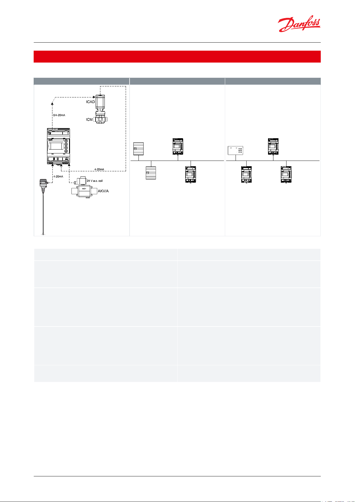
EKE 347 assembly
MODBUS communication
Remote Display - option
Danfoss
M84H0081_1
AKS 4100/
AKS 4100U
EKE 347
Danfoss
M84H0086_1
PLC
Master
PLC
Slave
EKE 347
Slave
EKE 347
Slave
MODBUS-RTU network
Danfoss
M84H0087_1
Remote
display
EKE 347
EKE 347
Danfoss CAN bus
EKE 347
Signaltransmitter
With the guided micro wave rod AKS 4100/4100U it is possible to set the refrigerant level within a wide range.
EKE 347
The controller receive a signal which enable it to contol low or high side applications (see page 3).
EKE 347 does support 2 types of Danfoss expansion valves. (see below) One
analog input is available as feed back from ICM in order to indicate opening
degree of the ICM.
Expansion valves
Two types of Danfoss expansion valves can be used
ICM
ICM are direct operated motorized valves
driven by digital stepper motor type ICAD
AKV/A
AKVA or AKV are pulse-width modulating
expansion valves.
MODBUS communication
EKE 347 include as standard RS 485 based MODBUSRTU bus communication interface to third
party equipment like PLC.
Via the MODBUS it is possible to read and write
parameters to the EKE 347
Operation, monitoring and data collection can
then be performed via PLC from a SCADA system.
Remote Display - option
A remote display for panel mounting is available. From the remote display a full
overview and access is possible to all individual EKE 347 controllers connected to
the internal Danfoss CAN bus.
Liquid level controller, Type EKE 347
Functions
Table 1: Functions
Table 2: Functions
© Danfoss | Climate Solutions | 2021.02 AI190286434038en-000501 | 3
ICM with
ICAD mo tor
EKE 347
AKS 4100/
AKS 4100U
AKS 4100/
AKS 4100U
EKE 347
Liquid level controller, Type EKE 347
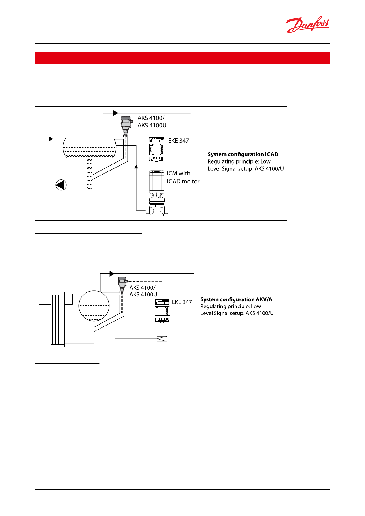
Applications
Pump reservoir
Modulating control of injection for a more stable liquid level and suction pressure.
Figure 1: System conguration ICAD
Separator on ooded evaporator
Modulating control and the valve’s large capacity range ensure a stable level - even under conditions of quickly
changing loads.
Figure 2: System conguration AKV/A
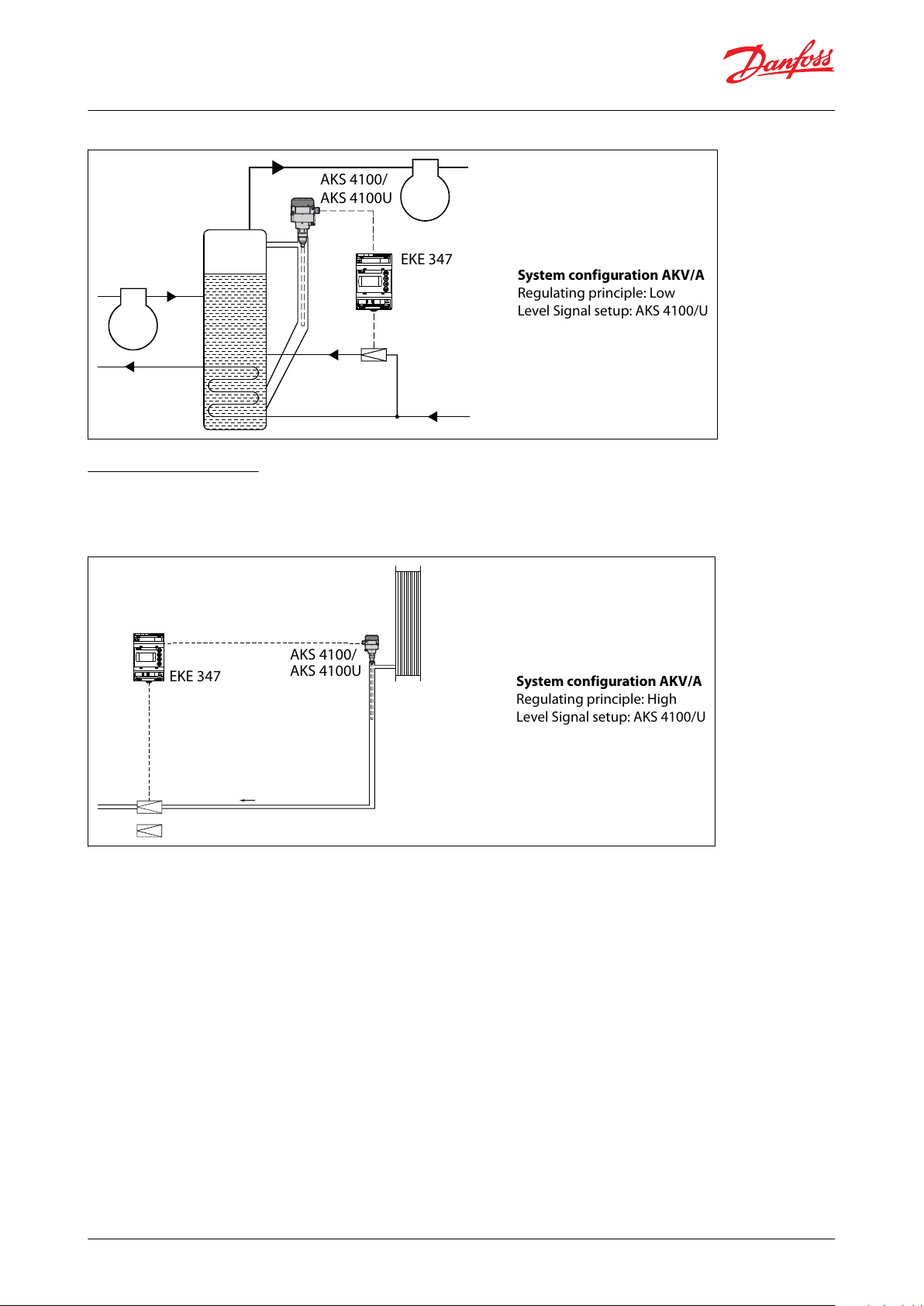
Intermediate cooler
The level transmitter’s wide measuring range enables it to monitor the liquid at all levels of the reservoir - and hence
to use the signal for safety functions in connection with the max. permissible level.
© Danfoss | Climate Solutions | 2021.02 AI190286434038en-000501 | 4
EKE 347
AKS 4100/
AKS 4100U
System configuration AKV/A
Regulating principle: Low
Level Signal setup: AKS 4100/U
EKE 347
AKS 4100/
AKS 4100U
System configuration AKV/A
Regulating principle: High
Level Signal setup: AKS 4100/U
Liquid level controller, Type EKE 347
Figure 3: System conguration AKV/A
Receiver / condenser
The control system’s short reaction time makes it very suited for high-pressure oat systems with small refrigerant
charges.
Figure 4: System conguration AKV/A
© Danfoss | Climate Solutions | 2021.02 AI190286434038en-000501 | 5
Supply voltage
24 V AC ±20% 50 / 60 Hz or 24 V DC ±20% (the supply voltage is galvanically separated from the input and
output signals. Input/output are not individual galvanic isolated)
Power consumption
Controller
20 W coil for AKV or AKVA
15 VA / 10W
55 VA
Input signal
* Ri =
0(4) – 20mA: 33 ohm
0(2) – 10 V: 100 kohm
Level signal *
4 – 20 mA or 0 – 10 V
ICM valve feedback signal *
From ICAD 0/4 – 20 mA
Contact function start / stop of regulation
Relay output
3 pcs. SPDT (Lower level alarm, Upper level alarm,
Common alarm / NC Solenoid)
Normally Open:
3 A GP*, 2.2 FLA / 13.2 LRA, 1/6 hp, PD 220 VA, 250 V
AC 100 k
3 FLA / 18 LRA, 1/10 hp, PD 150 VA, 125 V AC 100 k
Normally Closed:
3 A GP*, 250 V AC 100 k
(*GP = General purpose)
Max 240 V AC or 24 V AC / DC can be used, but same
voltage type must be used on DO3 and DO2
Current output
0 – 20 mA or 4 – 20 mA
Max. load: 500 ohm
Valve connection
ICM - via current output
AKV/A- via 24 AC Pulse-Width Modulating output
Data communication
MODBUS RTU: Communication to system controller,
MODBUS on RS485: galvanic isolation (500 V DC)
CAN: Communication to other EKE controllers
Supported Modbus Commands
Supported commands with max of 50 ms response
time
03 (0x03) Read Holding Registers
04 (0x04) Read Input Registers
06 (0x06) Write Single Register
Supported commands without
dened max response
time
08 (0x08) Diagnostics
16 (0x10) Write Multiple Registers (up to 20 registers)
43 (0x2b) Read Device
Identication
Environments
-20 °C – 55 °C, during operation
-30 °C – 80 °C, during storage
90% Rh, not condensed
No shock
inuence / vibrations
Enclosure
IP20 / IP40 for the front mounted into a panel
Weight
193 g
Mounting
DIN rail
Display
Graphical LCD display
Terminals
plugs 1.5 or 2.5 mm2 multicore
Terminals
28-29
Supply voltage 24 V a.c. or d.c.
1-7
Signal from level transmitter type AKS 4100/4100U
7-10
Signal from level transmitter type AKS 41
36-37
Expansion valve type AKV or AKVA
23-24
Expansion valve type: ICM with ICAD
13-14
Switch function for start/stop of controller. If a switch is not connected, terminals 13 and 14 must be shortcircuited
Liquid level controller, Type EKE 347
Product specication
Electrical connection
Table 3: Electrical connection
Material specication
Table 4: Material specication
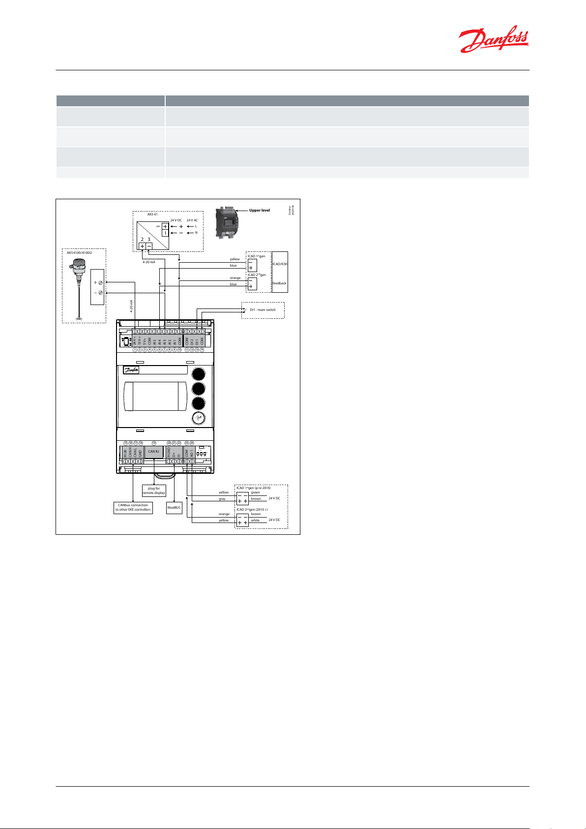
Connection
Table 5: Necessary connections
NOTE:
See the gures on the next pages.
© Danfoss | Climate Solutions | 2021.02 AI190286434038en-000501 | 6
AKS4100 /4100U
AKS 41
DI1 - main switch
4-20 mA
CANbus connection
to other EKE controllers
plug for
remote display
ModBUS
4-20 mA
24V DC
yellow
blue
orange
ICAD 1stgen
ICAD/ICM
feedback
ICAD 2ndgen
blue
24V AC
L
N
+
–
1
2 3
yellow
gray
orange
ICAD 1stgen (p re 2010)
ICAD 2ndgen (2010 +)
yellow
green
brown
brown
white
24V+
15V+
5V+
COM
AI 5
AI 4
AI 3
AI 2
AI 1
COM
COM
DI 2
DI 1
COM
R120
CAN H
CAN L
GND
R GNDD+D-
COM
AO 1
CAN RJ
24V DC
24V DC
1
15 16 17 18 19 20 21 22 23 24
2 3 4 5 6 7 8 9 10 11 12 13 14
Upper level
Danfoss
80Z8109
Terminals
33-35
Relay for common alarm. Installer can choose between Normally Open (33-34) or Normally Closed (34-35) circuits. The relay
will switch according to the programmed setting
25-27
Relay for low level limit. Installer can choose between Normally Open (26-27) or Normally Closed (25-26) circuits. The relay will
switch when the set value is passed.
30-32
Relay for upper level limit. Installer can choose between Normally Open (30-31) or Normally Closed (31-32) circuits. The relay
will switch when the set value is passed.
6-10
ICM valve feedback signal from ICAD 0/4 – 20 mA
Liquid level controller, Type EKE 347
Table 6: Application dependent connections
Figure 5: Connections - Upper level
© Danfoss | Climate Solutions | 2021.02 AI190286434038en-000501 | 7

–/~
NO 4
NC 3
C 3
NO 3
NC 2
C 2
NO 2
-/~
+/~
NO 1
C 1
NC 1
POWER
SUPPLY
AKV/AKVA
24V AC
+/- 20% 15VA
24V DC
+/- 20% 10W
–
Common
Normally Open or
Normally Closed
Low Level Alarm
Normally Open or
Normally Closed
High Level Alarm
Normally Open or
Normally Closed
+
37
29
28 27 26 25
36 35 34 33 32 31 30
NC 2
C 2
NO 2
NC 3
C 3
NO 3
NO 1
C 1
NC 1
Lower level
Note:
AKV(A) Coil voltage must be the same
as controller supply voltage AC or DC
Danfoss
80Z8110
–/~
NO 4
NC 3
C 3
NO 3
NC 2
C 2
NO 2
–
+
NO 1
C 1
NC 1
POWER
SUPPLY
Voltage:
24 - 230 V a.c.
Danfoss
80Z8111
Liquid level controller, Type EKE 347
Figure 6: Connections - Lower level
Figure 7: EKE 347 - ON/OFF Application. Open/Close solenoid valve with coil 24 V - 230V
© Danfoss | Climate Solutions | 2021.02 AI190286434038en-000501 | 8

AKS 4100/
AKS 4100U
Danfoss
M84H0075_1
AKS 41/
AKS 41U
Danfoss
M84H0076_1
AKS 4100/
AKS 4100U
Danfoss
M84H0077_1
AKS 4100/
AKS 4100U
Danfoss
M84H0078_1
Back
Press and hold = Log Out
Scroll up
Scroll down
Enter
Press and hold = Log In
Home Image
Danfoss
80Z8104_MS
Controller name
Actual liquid le vel
Valve opening deg ree
Flashing bell = Activ e alarm
Controller mode
Lower level alarm of (pump on)
Upper level alarm of
Danfoss
80Z8105_MS
Liquid level controller, Type EKE 347
Table 7: Connection examples
Control Panel
Figure 8: Control Panel
The user interface of the control panel consists of a multiline display and 4 individual push buttons: Enter button,
Scroll up button, Scroll down button and Back button.
The gure shows the Home display image, which give the actual overview. This is the starting point for entering into
menus, and you will revert to this image by pushing 1 – 3 times (depending on actual position).
Display
Figure 9: Display
The display itself show the state of Liquid level, Controller Mode (controller On/O), Valve opening degree,
Lower level alarm (o = no alarm present) and Upper level alarm (o = no alarm present).
© Danfoss | Climate Solutions | 2021.02 AI190286434038en-000501 | 9

Options
Setpoint
Liquid level setpoint
0 – 100% *)
Active alarms
Example of alarm content. The list will be empty in normal operation as no alarm is active.
Level signal out of range
hours minutes **)
Standby mode
hours minutes **)
Detailed status
Controller state
Stop, Manual, Auto, Slave, IO **)
Actual level
0.0 – 100% **)
Actual reference
0.0 – 100% **)
Actual OD
0.0 – 100% **)
Digital input status
On /
O **)
Actual level signal current
mA **)
Oscillation amplitude
0.0 – 100% **)
Oscillation period
sec **)
Controller Info
Type
**)
Name (Controller name)
**)
SW (Software version)
**)
Bios (Bios version)
**)
Adr (Controller address)
**)
SN (Serial Number)
**)
PV (Product version)
**)
Site (Production site)
**)
QR code
Code
**)
Liquid level controller, Type EKE 347
Additional to the external connected alarm audio/video sources, a Bell symbol will ash in the upper right corner in
case of an alarm.
To see more details on system performance and setting of parameters, 2 dierent main menu levels can be reached
by operation of the push buttons.
From Home image the Status menu can be reached by 1 push on Enter. From Home image the Setup & service
menu can be reached by 1 push and hold on Enter. For entrance a Log In is required by the password given during
Commisioning.
Menus
Status menu
To enter Status menu from Home image: Push once.
Figure 10: Status menu
The Status menu is an open menu accessible for all. Therefore only 1 parameter can be changed from here. A
selection of other parameters can be seen from the status menu.
Table 8: Status menu ( Open menu )
NOTE:
*) Read & write
**) Write only
Setup & service menu (Requires log-in password assigned in Commisioning menu)
To enter Setup and service menu from Home image: Push and hold
© Danfoss | Climate Solutions | 2021.02 AI190286434038en-000501 | 10

Parameter
Options
Default values
Read & Write
Read only
Reference
Main switch
On, OO
Yes
_
Liquid level setpoint
0 – 100%
50.00%
_
Operation mode
Master, IO, Slave
Master
_
Alarm setup
Lower level limit
0 – 100%
15%
Yes
_
Upper level limit
0 – 100%
85%
_
Level alarm mode
Time, Hysteresis
Time
_
Lower delay
0 – 999 sec
10 sec
_
Upper delay
0 – 999 sec
50 sec
_
Lower level hysteresis
0 – 20%
3%
_
Upper level hysteresis
0 – 20%
5%
_
Function common alarm
Not follow; Follow up; Fol-
low low; Follow all
Not follow
_
Oscillation detect band
0 – 100%
100%
_
Oscillation detect timeout
2 – 30 min
20 min
_
Force pump OFF in stop mode
Yes / No
No
_
IO Lower level limit
0 – 100%
5%
_
IO Upper level limit
0 – 100%
95%
_
IO Lower level hysteresis
0 – 20%
3%
_
IO Upper level hysteresis
0 – 20%
3%
_
IO Lower delay
0 – 999 sec
10 sec
_
IO Upper delay
0 – 999 sec
50 sec
_
IO Level limit
0 – 100%
50%
_
IO Level delay
0 – 999 sec
10 sec
_
IO Level hysteresis
0 – 20%
3%
_
IO Level action
Falling,Rising
Falling
_
Liquid level controller, Type EKE 347
Maneuvering in the Status menu and the Setup and service menu’s are done by use of the 4 push buttons shown on
page 4.
Figure 11: Setup & service menu
The Setup & service menu is divided into 3 access levels, where personnel have individual authority.
Most advanced level is Commissioning, where you have access to change all allowable parameters, including
password issuing and re-run of Setup wizard.
Service level is for service personnel and has fewer rights than commissioning.
The lowest level is for Daily use, and allows only a few changes.
The table on the next page shows authority given to the Commisioning level.
Table 9: Setup & service menu - COMMISSIONING
© Danfoss | Climate Solutions | 2021.02 AI190286434038en-000501 | 11

Parameter
Options
Default values
Read & Write
Read only
Control
Control Method
On/O ,P, PI
PI
Yes
_
Regulating principle
Low, High
Low
_
P-band
5 – 200%
30.00%
_
Integration time Tn
60 – 600 sec
400 sec
_
Neutral zone
0 – 25%
2.00%
_
Dierence
0,5 – 25%
2%
_
Period time for AKV/AKVA
3–15 sec
6 sec
_
Minimum OD
0 – 99%
0%
_
Maximum OD
1 – 100%
100%
_
Display
Language
EN,CN,PT,RU,SP,FR,IT, GER,
ARAB
EN
Yes
_
Output indication
level, OD
Level
_
Login timeout
1 – 120 min
10 min
_
Backlight timeout
0 – 120 min
2 min
_
Password daily
3 - digit, 0 – 999
100
_
Password service
3 - digit, 0 – 999
200
_
Password commission
3 - digit, 0 – 999
300
_
IO cong
System conguration
ICAD+NC, ICAD, AKV/A+NC,
AKV/A, NC only
ICAD + NC
Yes
_
Level signal setup
AKS 4100, AKS 41, Current,
Voltage
AKS4100
_
Voltage at low liquid level
0 – 10V
0 V
_
Voltage at high liquid level
0 – 10V
10 V
_
Current at low liquid level
0 – 20 mA
4 mA
_
Current at high liquid level
0 – 20 mA
20 mA
_
Valve position setup
Not used, Current, Voltage
Not used
_
Voltage at closed valve position
0 – 10V
0 V
_
Voltage at open valve position
0 – 10V
10 V
_
Current at closed valve position
0 – 20 mA
4 mA
_
Current at open valve position
0 – 20 mA
20 mA
_
Common alarm setup
D04, High alarm, D03, Disp
only
High alarm
_
Multiple valve setup
Not used, 2 same cap, 2 dif
cap, 3 same cap, 3 dif cap
Not used
_
Multiple valve pattern
Parallel,Sequence
Parallel
_
Valve A capacity
0 – 100%
50%
_
Valve B capacity
0 – 100%
50%
_
Valve C capacity
0 – 100%
30%
_
ICAD takeover OD
0 – 100%
80%
_
IO module setup
Used, Not used
Not used
_
Liquid level controller, Type EKE 347
© Danfoss | Climate Solutions | 2021.02 AI190286434038en-000501 | 12

Parameter
Options
Default values
Read & Write
Read only
Communication
CAN ID
1 – 127
1
Yes
_
CAN baudrate
20k, 50k, 125k, 250k, 500k,
1M
500k
_
Modbus ID
0 – 120
1
_
Modbus baudrate
0, 1200, 2400, 4800, 9600,
14400, 19200, 28800, 38400
19200
_
Modbus mode
8N1, 8E1, 8N2
8.00E+01
_
Modbus mapping
Operation, Setup
Operation
_
Valve B CAN ID
1 – 127
2
_
Valve C CAN ID
1 – 127
3
_
IO Mod. CAN ID
1 – 127
4
Yes
Service
Controller state–_
Actual level–_
Actual referrence–_
Actual OD–_
Actual valve position
_
Digital input status
–
_
Actual level signal voltage
_
Actual level signal current
–
_
Actual position signal voltage
_
Actual position signal current
_
Actual OD A
_
Actual OD B
_
Actual OD C
_
Manual Mode
On, O
O
Yes
_
Manual OD
0 – 100%
50.00%
_
Manual low alarm
O-OnO_
Manual high alarm
O-OnO_
Manual common alarm
O-OnOn_
Apply defaults
None, Factory
None
_
Setup wizard
Setup wizard
Re-run Setup wizard
–
Yes
_
I/O check
Main switch EKE act:
O
_
Yes
AKS 4100 EKE act:
–
_
ICAD EKE act:–_
Nor. Close (NC) EKE act:
–
_
Upper lvl (alarm) EKE act:
–
_
Lower lvl (alarm) EKE act:
–
_
Controller name
Controller name
Type in controller name
–
Yes
Upper level
Lower level
Standby mode
Valve B CAN ID
conict
Valve C CAN ID
conict
IO module CAN ID
conict
IO module communication
Communication to master lost
Min / max OD
conict
Common alarm HW
conict
Control method
conict
Multiple valve setup
conict
Liquid level controller, Type EKE 347
Alarm and error codes:
When detecting an alarm from external sources or the ashing bell in the display, the alarm description can be
found as a text message in the Status menu under Active alarms.
Both alarms and errors will be shown here. If more alarms/errors occur simultaneously, they will be shown as
subsequent text lines.
Table 10: Alarms:
© Danfoss | Climate Solutions | 2021.02 AI190286434038en-000501 | 13

Valve C alarm
Valve B alarm
Oscillation in level signal
Valve position
Multiple valve capacity
Valve C communication
Valve B communication
Internal error
Level signal out of range
Valve position signal out of range
Sensor supply overload
AKS 4100 error
Too much current AI3
Too much current AI4
DO4 overload
AKS 4100/
AKS 4100U
Danfoss
80Z8113
MASTER
SLAVE 1
SLAVE 2
AKVA
(ICAD)
AKVA
(ICAD)
AKVA
(ICAD)
R120
CAN H
CAN L
GND
15 16 17 18
R120
CAN H
CAN L
GND
15 16 17 18
R120
CAN H
CAN L
GND
15 16 17 18
Jumper
15-16
Jumper
15-16
When more controllers are
connected via CAN bus each
end of the bus must be
terminated with a jumper
between 15 and 16.
Liquid level controller, Type EKE 347
Table 11: Errors:
MASTER / SLAVE conguration
Figure 12: MASTER / SLAVE conguration
Multivalve
If the system capacity requires more than one control valve; up to three valves can be controlled simultaneously in a
Master/Slave conguration, where the master and each slave controls one valve respectively.
EKE 347 IO cong menu - Multiple valve setup - with one of these options:
• 2 valves with same capacity
• 2 valves with dierent capacity
• 3 valves with same capacity
• 3 valves with dierent capacity
Additionally the master must be programmed in IO cong menu - Multiple valve pattern - for either:
• Valves in parallel (valves regulate simultaneously) or
• Valves sequential (mainly one valve regulating at any time)
See principle below.
The slave EKE’s only need identication of Slave and valve CAN ID (communication menu).
© Danfoss | Climate Solutions | 2021.02 AI190286434038en-000501 | 14

Capacity
Capacity
Opening degreeOpening degree
Valve B
Valve A
Valve B
Valve A
Two identical v alves (Parallel) Two identical v alves (Sequential)
Danfoss
80Z8114
AKS 4100/
AKS 4100U
Danfoss
M84H0084_1
MASTER
I/O
AKVA
(ICAD)
R120
CAN H
CAN L
GND
15 16 17 18
R120
CAN H
CAN L
GND
15 16 17 18
Jumper
15-16
Jumper
15-16
D02
D03
D01
NC 2
C 2
NO 2
NC 3
C 3
NO 3
NO 1
C 1
NC 1
Liquid level controller, Type EKE 347
Figure 13: Valves in parallel and Valves sequential
The default display of the master EKE will show the standard information together with a symbol of multiple valves
and the actual total opening degree (see below).
The default display of the slave EKE will show the actual liquid level (as the master), symbol of multiple valves, actual
total opening degree and the opening degree of the individual valves involved (see below).
I/O conguration
Figure 14: I/O conguration
Remote display
The daily operation can be set up directly on the controller or via an external display device.
© Danfoss | Climate Solutions | 2021.02 AI190286434038en-000501 | 15

Termination
Termination
Termination Termination
Termination Termination
Liquid level controller, Type EKE 347
Figure 15: Example 1
Figure 16: Example 2
Figure 17: Example 3
ERR31
Alarm on the external display - MMIGRS2
If the communication to the display is not carried out correctly, it will send an “ERR31” error notication. This may be
caused by the displayed terminations not being installed, or that there have been interruptions in data
communication during the time when the display retrieves the basic information from the controller. Once the
© Danfoss | Climate Solutions | 2021.02 AI190286434038en-000501 | 16

Label
Parameter name
Min value
Max val‐
ue
Default
Unit
Decimals
Modbus
PNU
Locked
by main
switch
EEPROM
Enumeration
r12
Main switch
01003001NOYES
0 =
O | 1 = On
R01
Liquid level setpoint
0
10050%13002NOYES
N07
Operation Mode
02003003
YES
YES
0 = Master | 1 = Slave | 2 =
IO
a02
Lower level limit
0
10015%03004NOYES
a01
Upper level limit
0
10085%03005NOYES
a07
Level alarm mode
01003006NOYES
0 = Time | 1 = Hysteresis
a04
Lower delay
0
99910s03007NOYES
a03
Upper delay
0
99950s03008NOYES
a06
Lower level hysteresis
0203%1
3009NOYES
a05
Upper level hysteresis
0205%1
3010NOYES
a08
Function common alarm
03003011NOYES
0 = Not follow | 1 = Follow
up | 2 = Follow low | 3 = Fol-
low all
a12
Oscillation detect band
0
100
100%0
3012NOYES
a13
Oscillation detect timeout
23020
min03013NOYES
a25
Force pump OFF in stopped
mode
01003117NOYES
0 = O | 1 = On
a14
IO Lower level limit
0
1005%03101NOYES
a15
IO Upper level limit
0
10095%03102NOYES
a16
IO Lower level hysteresis
0203%1
3103NOYES
a17
IO Upper level hysteresis
0203%1
3104NOYES
a18
IO Lower delay
0
99910s03105NOYES
a19
IO Upper delay
0
99950s03106NOYES
a20
IO Level limit
0
10050%03107NOYES
a21
IO Level delay
0
99910s03108NOYES
a22
IO Level hysteresis
020313109NOYES
a23
IO Level action
01003110NOYES
0 = Falling | 1 = Rising
N03
Control Method
02203014NOYES
0 = On /
o | 1 = P-ctrl | 2 =
PI-ctrl
n35
Regulating principle
01003015NOYES
0 = Low | 1 = High
Liquid level controller, Type EKE 347
terminations have been inspected, you should then check the software version of the external display. This is done
by holding down the Enter key and the X key for 5 seconds, until the Bios menu appears. Next, press the X key and
read o the software version in the bottom right corner. The software version must be 1.13 or newer.
Once the display’s software version has been checked, check the display’s settings as follows:
1.
Hold the Enter key and the X key down for 5 seconds, until the Bios menu appears
2.
Select the “MCX selection” menu
2.1.
Select the “Clear UI” line and press Enter
2.2.
Select the “Autodetect” line and press Enter
3.
Press the X key to return to the Bios menu
4.
Select the “COM selection” menu
4.1.
Select the “CAN” line and press Enter
5.
Press the X key to return to the Bios menu
6.
Select the “Start up mode” menu
6.1.
Select the “Remote application” line and press Enter
7.
Press the X key to return to the Bios menu
8.
Select the “CAN” menu
8.1.
Select the “Baudrate” line and then select the “Autobaud” setting and press Enter
8.2.
Select the “Node ID” line and set the value to 126 and press Enter
9.
Press the X key to return to the Bios menu
10.
Select the “Application” menu and press Enter
NOTE:
The display will once again retrieve data from the controller. This process will take about 5 minutes.
Modbus parameters
Table 12: Software version: 1.62.xx
© Danfoss | Climate Solutions | 2021.02 AI190286434038en-000501 | 17

Label
Parameter name
Min value
Max val‐
ue
Default
Unit
Decimals
Modbus
PNU
Locked
by main
switch
EEPROM
Enumeration
n04
P-band520030%13016NOYES
n05
Integration time Tn
60
600
400s0
3017NOYES
n34
Neutral zone
0252%1
3018NOYES
N06
Dierence
0,5252%1
3019NOYES
n13
Period time for AKV / AKVA
3156s1
3020NOYES
n33
Minimum OD
00%03021NOYES
n32
Maximum OD
1
100
100%0
3022NOYES
o11
Language0000
3023
YES
YES
0 = $ActiveLanguageList
o17
Output indication
01003024NOYES
0 = Level | 1 = OD
K04
Login timeout
1
12010min03025NOYES
K06
Backlight timeout
0
1202min03026NOYES
o05
Password daily
0
999
10003027NOYES
K02
Password service
0
999
20003028NOYES
K03
Password commission
0
999
30003029NOYES
K05
Contrast010040%03030NOYES
K01
Brightness
0
10080%03031NOYES
I09
System conguration
04003032
YES
YES
0 = ICAD+NC | 1 = ICAD | 2 =
AKV/A+NC | 3 = AKV/A | 4 =
NC only
o31
Level signal setup
03003033
YES
YES
0 = AKS4100 | 1 = AKS41 | 2
= Current | 3 = Voltage
o32
Voltage at low liquid level
00V13034NOYES
o33
Voltage at high liquid level
1010V13035NOYES
I06
Current at low liquid level
04mA13036NOYES
I07
Current at high liquid level
2020mA13037NOYES
o34
Valve position setup
02003038
YES
YES
0 = Not used | 1 = Current |
2 = Voltage
I02
Voltage at closed valve position
00V13039NOYES
I03
Voltage at open valve position
1010V13040NOYES
I04
Current at closed valve position
04mA13041NOYES
I05
Current at open valve position
2020mA13042NOYES
I18
Common alarm setup
03103043
YES
YES
0 = DO4 | 1 = High Alarm | 2
= DO3 | 3 = Disp only
I08
Multiple valve setup
04003044
YES
YES
0 = Not used | 1 = 2 same
cap | 2 = 2 dif cap | 3 = 3
same cap | 4 = 3 dif cap
I13
Multiple valve pattern
01003045NOYES
0 = Parallel | 1 = Sequence
I10
Valve A capacity
0
10050%03046
YES
YES
I11
Valve B capacity
0
10050%03047
YES
YES
I12
Valve C capacity
0
10033%03048
YES
YES
I17
ICAD takeover OD
0
10080%03052NOYES
I19
IO module setup
01003091
YES
YES
0 = Not used | 1 = Used
G01
CAN ID112710
4032NONO
G02
Can baudrate
05404033NONO
0 = 20k | 1 = 50k | 2 = 125k |
3 = 250k | 4 = 500k | 5 = 1M
G06
Modbus ID
0
12010
3055NOYES
G05
Modbus baudrate
08603056NOYES
0 = 0 | 1 = 1200 | 2 = 2400 | 3
= 4800 | 4 = 9600 | 5 =
14400 | 6 = 19200 | 7 =
28800 | 8 = 38400
G08
Modbus mode
02103057NOYES
0 = 8N1 | 1 = 8E1 | 2 = 8N2
G07
Modbus mapping
01003058NOYES
0 = Operation | 1 = Setup
G09
Valve B CAN ID
1
12720
3088
YES
YES
G10
Valve C CAN ID
1
12730
3089
YES
YES
G11
IO Mod. CAN ID
1
12740
3090
YES
YES
Liquid level controller, Type EKE 347
© Danfoss | Climate Solutions | 2021.02 AI190286434038en-000501 | 18

Label
Parameter name
Min value
Max val‐
ue
Default
Unit
Decimals
Modbus
PNU
Locked
by main
switch
EEPROM
Enumeration
B01
Controller state
06004001
YES
NO
0 = Powerup | 1 = Stop | 2 =
Auto | 3 = Manual | 4 = Slave
| 5 = IO | 6 = Safe
u01
Actual level
0
1000%14002NONO
u02
Actual reference
0
1000%14003
YES
NO
u24
Actual OD01000%14004NONO
u33
Actual valve position
0
1000%14005NONO
u10
Digital input status
01004006NONO
0 = O | 1 = On
u31
Actual level signal voltage
0
1000V14007NONO
u30
Actual level signal current
0240mA1
4008NONO
B02
Actual position signal voltage
0
1000V14009NONO
u32
Actual position signal current
0
1000mA14010NONO
B03
Actual OD A
0
1000%14011NONO
B04
Actual OD B
0
1000%14012NONO
B05
Actual OD C
0
1000%14013NONO
o18
Manual Mode
01004014NONO
0 = O | 1 = On
o45
Manual OD
0
10050%13059NONO
B08
Manual low alarm
01003060NONO
0 = O | 1 = On
B06
Manual high alarm
01003061NONO
0 = O | 1 = On
B07
Manual common alarm
01003062NONO
0 = O | 1 = On
B09
Apply defaults
01003063
YESNO0 = None | 1 = Factory
B11
Oscillation amplitude
0
1000%14028
YES
NO
B10
Oscillation period
0
36000s04029
YES
NO
Label
Alarm name
Modbus PNU
Bit number
A1
Upper level
1901
8
A2
Lower level
1901
9
A92
Oscillation in level signal
1901
10
A96
Valve position
1901
14
A97
Multiple valve capacity
1901
15
E1
Internal error
1901
0
E21
Level signal out of range
1901
1
E22
Valve position signal out of range
1901
2
E96
AKS 4100 error
1901
3
A45
Standby mode
1901
4
A99
Valve B communication
1901
5
A98
Valve C communication
1901
6
A85
Communication to master lost
1901
7
A91
Valve B alarm
1902
8
A90
Valve C alarm
1902
9
A88
Control method conict
1902
10
A87
Common alarm HW conict
1902
11
A86
Min / max OD conict
1902
12
E95
Sensor supply overload
1902
13
E99
DO4 overload
1902
14
E97
Too much current AI3
1902
15
E98
Too much current AI4
1902
0
A89
Multiple valve setup conict
1902
1
A80
Valve B CAN ID conict
1902
2
A81
Valve C CAN ID conict
1902
3
A82
IO module CAN ID conict
1902
4
A83
IO module communication
1902
5
Liquid level controller, Type EKE 347
Table 13: Alarms
© Danfoss | Climate Solutions | 2021.02 AI190286434038en-000501 | 19

110
5
70
60
63
Danfoss
80G74_}01-2014
Liquid level controller, Type EKE 347
Dimensions and weights
Figure 18: EKE 347
© Danfoss | Climate Solutions | 2021.02 AI190286434038en-000501 | 20

Type
Description
Code No.
EKE 347
Liquid level controller
080G5000
MMIGRS2
Remote display, Panel, S
080G0294
Wire for display unit, L = 1.5 m, 1 pcs.
080G0075
Wire for display unit, L = 3 m, 1 pcs.
080G0076
EKE / EKC accessory for panel mounting
027F0309
Liquid level controller, Type EKE 347
Ordering
Table 14: Ordering
© Danfoss | Climate Solutions | 2021.02 AI190286434038en-000501 | 21

File name
Document type
Document topic
Approval authority
UA.1O146.D.00070-19
UA Declaration
EMCD/LVD
LLC CDC EURO-TYSK
RU Д-DK.ГА02.В.05523
EAC Declaration
EMC
EAC
080R4002.01
China RoHS
CRN
Danfoss
080R4000.02
CRN
Danfoss
EU Low Voltage Directive and EMC demands re CE-marking complied with.
LVD-tested acc. to EN 60730-1 and EN 60730-2-9
EMC-tested acc. to EN61000-6-3 and EN 61000-6-2
UL le E31024
Liquid level controller, Type EKE 347
Certicates, declarations, and approvals
The list contains all certicates, declarations, and approvals for this product type. Individual code number may have
some or all of these approvals, and certain local approvals may not appear on the list.
Some approvals may change over time. You can check the most current status at danfoss.com or contact your local
Danfoss representative if you have any questions.
Table 15: Valid Approvals
Table 16: Conformity Approvals
© Danfoss | Climate Solutions | 2021.02 AI190286434038en-000501 | 22

Online support
Danfoss oers a wide range of support along with our products, including digital product information, software,
mobile apps, and expert guidance. See the possibilities below.
The Danfoss Product Store
The Danfoss Product Store is your one-stop shop for everything product related—no matter where
you are in the world or what area of the cooling industry you work in. Get quick access to essential
information like product specs, code numbers, technical documentation, certications, accessories,
and more.
Start browsing at store.danfoss.com.
Find technical documentation
Find the technical documentation you need to get your project up and running. Get direct access to
our ocial collection of data sheets, certicates and declarations, manuals and guides, 3D models
and drawings, case stories, brochures, and much more.
Start searching now at www.danfoss.com/en/service-and-support/documentation.
Danfoss Learning
Danfoss Learning is a free online learning platform. It features courses and materials specically
designed to help engineers, installers, service technicians, and wholesalers better understand the
products, applications, industry topics, and trends that will help you do your job better.
Create your Danfoss Learning account for free at www.danfoss.com/en/service-and-support/learning.
Get local information and support
Local Danfoss websites are the main sources for help and information about our company and
products. Find product availability, get the latest regional news, or connect with a nearby expert—all
in your own language.
Find your local Danfoss website here: www.danfoss.com/en/choose-region.
Spare Parts
Get access to the Danfoss spare parts and service kit catalog right from your smartphone. The app
contains a wide range of components for air conditioning and refrigeration applications, such as
valves, strainers, pressure switches, and sensors.
Download the Spare Parts app for free at www.danfoss.com/en/service-and-support/downloads.
Coolselector®2 - nd the best components for you HVAC/R system
Coolselector®2 makes it easy for engineers, consultants, and designers to nd and order the best
components for refrigeration and air conditioning systems. Run calculations based on your operating
conditions and then choose the best setup for your system design.
Download Coolselector®2 for free at coolselector.danfoss.com.
Danfoss can accept no responsibility for possible errors in catalogues, brochures and other printed material. Danfoss reserves the right to alter its
products without notice. This also applies to products already on order provided that such alterations can be made without subsequential
changes being necessary in specications already agreed. All trademarks in this material are property of the respective companies. Danfoss and
the Danfoss logotype are trademarks of Danfoss A/S. All rights reserved.
© Danfoss | Climate Solutions | 2021.02 AI190286434038en-000501 | 23
 Loading...