

Page 1
User Guide
Stepper Valve Extension Module
Type EKE 1P
ADAP-KOOL® Refrigeration Control System
www.danfoss.com
Page 2

User Guide | Stepper Valve Extension Module, Type EKE 1P
Contents
Introduction ................................................................................................................................................................................................................3
Application 1 ...............................................................................................................................................................................................................4
Application 2 ...............................................................................................................................................................................................................4
User Interface ..............................................................................................................................................................................................................5
End-user overview with graphical display .......................................................................................................................................................7
Service and commissioning with graphical display .....................................................................................................................................7
Menu ..............................................................................................................................................................................................................................8
Alarm list .................................................................................................................................................................................................................... 11
ERR31 .......................................................................................................................................................................................................................... 12
Connections ............................................................................................................................................................................................................. 13
Technical Data ......................................................................................................................................................................................................... 14
Installation considerations .................................................................................................................................................................................. 14
Mounting/dimensions .......................................................................................................................................................................................... 15
Ordering .................................................................................................................................................................................................................... 15
2 | BC320219567793en-000201 © Danfoss | DCS (vt) | 2020.03
Page 3
User Guide | Stepper Valve Extension Module, Type EKE 1P
EKE 1P
CCMT/ETS/CCM
80G394
100
%
%
80G395
CCMT/ETS/CCM
ACCCBI080G0075
Introduction
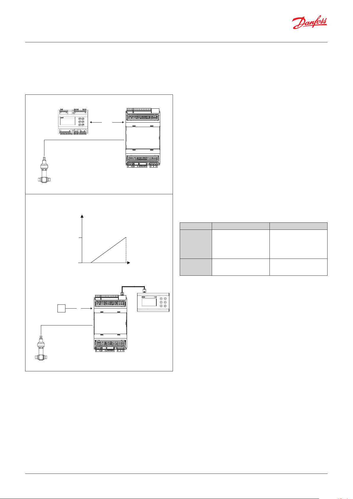
Application
The controller is used as an extension module for other Danfoss
controllers (application 1 below) or as a stepper valve driver
(application 2 below).
Application 1
CAN RJ
AK-PC
CAN
Application 2
Fig. 1
0
Min.
Max.
Danfoss
V
Input and output
In application mode 1, all input and output are defined via the
master controller AK-PC set-up.
In application mode 2, the input and output are intended for one
specific function.
The overview of connections can be seen on page 12.
Operation
The daily operation can be set up via an external display device
although this is normally not required for application 2.
The normal operation screen for application 1 is shown below.
During set-up, the display images will be adjusted so that only the
relevant images are opened for additional setting and end-user
operation.
The operation is password protected, and three levels of access
Danfoss
can be granted.
The controller contains English language only.
Two sets of LEDs on the EKE 1P indicate the EKE 1P application
confirmation, valve status and alarm condition – see details further
below.
Data communication
The controller has a built-in CANBUS and a built-in MODBUS
interface. The interfaces are used as shown in below table:
CANBUS MODBUS
Application 1 Interface to master
controller, AK-PC
Application 2 Configuration of EKE 1P
and daily use interface
MODBUS master
for establishing
communication with other
MODBUS devices to the
master controller, AK-PC
Not used – must not
be connected to any
MODBUS network
Fig. 2
PLC
< 3m
EKE 1P
CAN RJ
V
CAN RJ
MMIGRS2
Fail-safe valve closure
As a stepper valve is provided with step motor, it will remain open
in a power failure situation.
For safety reasons, the liquid flow through the stepper valve must
be cut off if a power failure occurs.
There are two ways of coping with this situation.
One of the following two solutions can be applied in the system:
• Mounting of a solenoid valve in front of EEV
• Connection of a battery back-up for EEV valve
Danfoss
80G396
If the battery back-up is used, the battery voltage may be
continuously monitored to generate an alarm in case the battery
voltage gets out of range. As default this alarm is disabled.
Advantages
• Simplified settings:
– For application 1, typically the controller needs no parameter
adjustment
– For application 2, only a few key parameter settings may be
required
• Power Supply:
– Easy wiring layout. With no risk of causing short circuits when
connecting to other units through power supply
– 24 V AC or 24 V DC: flexibility in selecting different transformers
• Universal valve support:
– Drives bipolar and unipolar valves
– Danfoss standard valves selectable through drop-down
– Flexible configuration of valve driver parameters for non-
Danfoss standard valves
© Danfoss | DCS (vt) | 2020.03 BC320219567793en-000201 | 3
Page 4

User Guide | Stepper Valve Extension Module, Type EKE 1P
Application 1
Application mode
In application 1, the EKE 1P operates as an extension module to a
CO pack controller, AK-PC. It is possible to configure if the EKE 1P
is used as an extension module where the stepper output controls
the high pressure, or as an extension module where the stepper
output controls the receiver pressure.
This is configurable through a software setting (parameter “Mode”)
or through a hardware configuration. As default the hardware
configuration is enabled, which means the AI4 input is used for the
configuration as follows:
AI4 open circuit or connected to 0 V (COM): high-pressure valve driver
AI4 connected to 5 V+: receiver valve driver
The IO configuration of application 1 is determined through the
configuration of the AK-PC.
Some, all or a sub-set of the inputs and outputs may be used.
See documentation of the specific AK-PC for details.
Valve configuration
In application mode 1, the valve type is configured via the AK-PC.
Only if the valve type is set to “User Defined” in the AK-PC, it is
required to access the EKE 1P parameter list for configuring the
valve specific parameters like number of steps, max current etc.
In application mode 1, the EKE 1P will set the valve opening
degree to a fixed value in case of losing the CANBUS
communication to the AK-PC. As default the valve will close in this
case.
Application 2
Valve configuration
The valve type can be selected from an extensive list of Danfoss
standard valve types. When a standard type is selected, only a
few parameters need to be set i.e. a valve neutral zone, the valve
overdrive and valve opening degree in special situations.
If Danfoss standard valve type is not selected, app. 20 parameters
for the valve and valve motor control become visible (“Valve motor
type”, “Valve drive current” etc.). See “Menu” for details.
Analogue input scaling
The EKE 1P may be configured for various voltage ranges, e.g.
2 – 10 V. Here the valve will be 0% open at 0 V and 100% open at
10 V and proportionally opened in values between. Typical input
ranges may be configured or the voltage range may be freely
configured within 0 – 10 V and 10 – 0 V.
Note: if the minimum is set to 0 V, the valve will start opening at
0.1 V to ensure detection of a valve closure signal (0 V).
Valve neutral Zone
The EKE 1P controller has a complex algorithm implemented to
handle oscillation issues related to output valve OD by defining
some neutral zone. In neutral zone, the valve will not move until it
overcomes the definite variation in the valve opening degree.
Valve Overdrive
To compensate for lost steps, the valve may be overdriven when it
closes to 0%. i.e. it will close with extra steps to make sure that it is
fully closed. This may, however, lead to increased wear on the valve
if it occurs frequently. To prevent this, the overdrive will only be
enabled when the valve opening degree exceeds a set value and
the overdrive function may only re-occur within a set interval.
4 | BC320219567793en-000201 © Danfoss | DCS (vt) | 2020.03
Page 5
User Guide | Stepper Valve Extension Module, Type EKE 1P
0s 2s1s
G
0s 2s1s
RR
GGGG
0s 2s1s
GG
0s 2s1s
GGGG
GGGG
0s 2s1s
G
0s 2s1s
G
0s 2s1s
G G GG
0s 2s1s
GGGG
GGGG
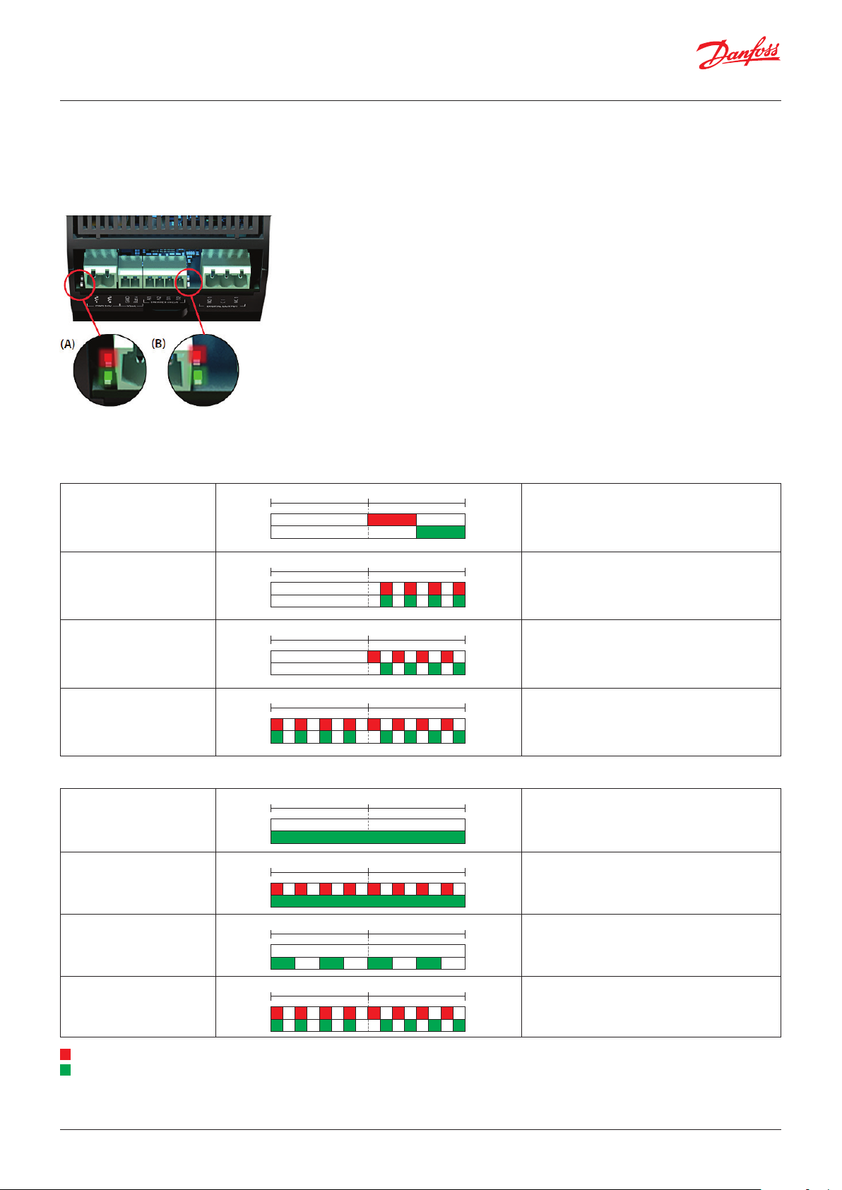
User Interface
LED alarm and status indication
LED indication:
Two sets of Light Emitting Diodes make it possible to follow the operation status of the valve and the controller.
Red
Green
Red
Green
LED A: Two status LEDs indicate power and controller operation
Power-up:
1. AI valve driver module
R
2. HP module
RR
3. Receiver module
RRRR
GG
RRRR
RRRR
Configured as AI controlled stepper valve will blink for 30 sec. after power-up.
Configured as HP module will blink for 30 sec. after power-up.
Configured as receiver module will blink for 30 sec. after power-up.
Hardware problem.
Normal operation:
4. Power
5. MODBUS error power
6. Power main switch OFF
R
= Red
G
= Green
© Danfoss | DCS (vt) | 2020.03 BC320219567793en-000201 | 5
Pattern during normal operation.
Pattern during normal operation,
but MODBUS error.
RRRRRRRR
Pattern during normal operation,
main switch = OFF.
Hardware problem.
RRRR
RRRR
Page 6

User Guide | Stepper Valve Extension Module, Type EKE 1P
0s 2s1s
R
0s 2s1s
RRRRRRRR
0s 2s1s
0s 2s1s
GG
0s 2s1s
G
LED B: Two status LEDs to indicate valve operation
V1. Valve closed
Steady red = valve fully closed.
V2. Valve closing
V3. Valve idle
V4. Valve opening
V5. Valve open
R
= Red
G
= Green
Flashing red (2 Hz) = valve closing.
Running on target.
Both Red and Green off.
Flashing green (2 Hz) = valve opening.
GGGG GG
Steady green = valve fully open.
6 | BC320219567793en-000201 © Danfoss | DCS (vt) | 2020.03
Page 7

User Guide | Stepper Valve Extension Module, Type EKE 1P
End-user overview with graphical display
The first screen in this daily user interface shows the status of the relevant inputs and outputs and will depend on how the set-up is
made (application mode).
Click on the ““ to view e.g. the following images:
Application 1 – High pressure:
Application 1 – Receiver pressure:
Application 2:
Service and commissioning with graphical display
To access the parameter menu, press and hold the “Enter” button for 3 seconds while the first screen in the daily user view (showing
input and output values) is displayed.
See next section for details.
© Danfoss | DCS (vt) | 2020.03 BC320219567793en-000201 | 7
Page 8

User Guide | Stepper Valve Extension Module, Type EKE 1P
Menu
Start/Stop
Main switch Main switch
Device config
Mode Selection of the application mode and how the device is used in application 1.
AI valve input scale Configuration of the Analogue Input in application mode 2. If user defined is selected,
System
Display Login time-out If buttons have not been pressed within a specified period of
Password The settings in the controller can be protected with three levels of access codes. The three access codes are numbers between
Reset to Factory Apply defaults This will reset the controller back to default (factory) settings On / Off
I/O
Input status AI 1 … AI 4 Here you can see pressure and temperature values received by
Output Relay state Here you can see if the function is on or off
Configure DI1 Active at ... DI2
Alarm config
Battery alarm If a battery back-up is connected to EKE 1P terminals, the EKE 1P will close the stepper
Start and stop regulating here.
The configuration settings will require that regulating is stopped.
If you try to enter a configuration setting when regulating has started, the controller will
ask if regulating should be stopped.
When all settings have been made and the main switch is set to “ON”, the controller will
enable the display of the various measurements. Regulation will start. (One external
main switch must be “ON” before regulation starts.)
Note: In application 1, the main switch automatically follows the main switch of the
AK-PC.
Note: changing this setting also changes the EKE 1P address, causing communication
with the graphical display to stop. Communication will resume after a power cycle.
AI HP/Rec.: Appl. 1 - selection by AI4
HP exp: Appl. 1 - High Pressure expansion module
Rec. exp.: Appl. 1 - Receiver Expansion module
AI valve: Appl. 2 - Valve Driver
the scaling is created via the two parameters, ”AI 0% OD” and ”AI 100%” OD which
become visible.
time, the screen will return to the overview display. Afterwards,
the user will have to log on again.
If the time is changed, the new time will apply the next time
the user logs in.
If you log out here without waiting for the time-out period
to elapse, go to the overview display and hold down the “X”
button for 3 seconds.
Display unit Temperature and Pressure unit Metric (°C & bar) / Imperial (°F & psig)
Backlight time-out If no buttons have been pushed for a specific period of time,
001 and 999.
Password daily Level 1: End user settings, such as changing the main switch Fac: 100
Password service Level 2: Adjusting installer level Fac: 200
Password commission Level 3: Configuration of system settings (configuration menu) Fac: 300
DI 1 … DI2 Here you can see the status of the digital input function/alarm
Relay control Manual control of relay in application 2. In application 1 the
Active at
motor if the controller loses its supply voltage. The battery voltage must not be
connected from main power supply connected to EKE 1P. A battery voltage lower than
16.5 V will trigger the battery alarm.
The battery back-up may be the Danfoss module (EKE 2U) or a general type (Bat.).
the light in the display will be minimised.
The light level will be restored upon renewed activity.
the analogue inputs. The values include calibration
manual control is done from the AK-PC controller.
Under normal regulation, the function of the relay will be in
“Auto”. In the event of an override, the function will be switched
to either “On” or “Off”. Remember to switch to “Auto” when the
override is to be completed. Otherwise it will remain in override
until the device is power cycled or reset to factory settings
Define whether the function/alarm will be active with terminals
short-circuited (ON) or open-circuited (OFF)
On / Off
Fac: Off
AI HP/Rec. / HP exp / Rec. exp. / AI valve
Fac: AI HP/Rec.
0 – 5 V / 1 – 5 V / 0 – 10 V / 2 – 10 V /
5 - 0 V / 5 – 1 V / 10 – 0 V / 10 – 2 V /
User Defined
Fac: 0 - 10V
Min: 1 min.
Max: 60 min.
Fac: 2 min.
Fac: Metric (°C & bar)
Min: 1 min.
Max: 60 min.
Fac: 1 min.
Fac: Off
Auto / On / Off
Fac: Auto
On / Off
Fac: On
No / Bat. / EKE2U
Fac: No
8 | BC320219567793en-000201 © Danfoss | DCS (vt) | 2020.03
Page 9

User Guide | Stepper Valve Extension Module, Type EKE 1P
Valve config
Any changes made to parameters in this group will only take effect after a restart of the
controller, e.g. by a power cycle or by toggling the main switch.
Valve configuration Application 1: Set from AK-PC except if the valve type is set to User Defined in AK-PC,
Valve fallback OD During fail-safe mode in application 1 (e.g. CANBUS signal lost), the valve will apply this
Valve motor type Define a type of motor used in the stepper valve (Unipolar/Bipolar). Unipolar / Bipolar
Valve drive current The current applied to each phase of the stepper motor during actual valve movement.
Valve step
positioning
Valve total steps The number of steps that correspond to changing the valve position from 0 – 100% OD. 1 – 8000 steps
Valve speed The desired valve drive rate in steps per second.
Valve start speed This is used to limit the starting speed of the valve in order to provide higher motor
Valve emengency
speed
Valve acceleration
current
Valve acceleration
time
Valve holding current The percent of the programmed Max Phase Current that should be applied to each
Valve step mode Stepper motor can be driven with various step excitation methods, depending on valve
Valve duty cycle The required valve duty cycle can be set between 5-100% using this parameter. 5 – 100%
Valve OD during stop The valve will apply this opening degree if the control is stopped (main switch off). 0 – 100%
Start backlash The parameter defines the operation of the start backlash function. The valve will
Compensation
backlash
Overdrive When the overdrive is enabled and the block timer has expired, next time the valve
Overdrive enable OD After being closed, the valve opening degree must exceed this value before the
Overdrive block time After an overdrive has occurred, the overdrive function may not occur again within this
Valve excitation time
after stop
then it is according to below list (see Application mode 2).
Application 2:
0 = no valve, 1 = UserDef,
2 = ETS 12C, 3 = ETS 24C, 4 = ETS 25C, 5 = ETS 50C, 6 = ETS 100C,
7 = ETS 6, 8 = ETS 12.5, 9 = ETS 25, 10 = ETS 50, 11 = ETS 100,
12 = ETS 250, 13 = ETS 400,
14 = KVS 2C, 15 = KVS 3C, 16 = KVS 5C,
17 = KVS 15, 18 = KVS 42,
19 = CCMT 0, 20 = CCMT 1,
21 = CCMT 2, 22 = CCMT 4, 23 = CCMT 8,
24 = CCMT 16, 25 = CCMT 24,
26 = CCMT 30, 27 = CCMT 42,
28 = CCM 10, 29 = CCM 20, 30 = CCM 30, 31 = CCM 40,
32 = CTR 20
33 = CCMT 3L, 34 = CCMT 5L, 35 = CCMT 8L
opening degree.
Entered as a peak value.
Read-out of the valve opening degree in number of steps.
Please note that a higher valve speed will produce a lower torque. If the valve is used in
systems having high differential pressure, it is better to operate the valve with a lower
step rate.
torque at start-up to prevent the valve from potential step loss.
During power failure conditions, the valve can be driven at higher speed when required
to close faster. This function requires a back-up battery connected to the EKE.
These features are used with valves running at higher speed i.e 300 pps and above.
Typically, at start-up high torque is required to operate the valve. The high torque at
start-up can be maintained by using acceleration current as required.
phase of the stepper output when the valve is stationary. If required, this current
ensures that the valve maintains its last programmed position.
requirements and operating conditions.
The valves can be driven in full step 1/1, half step 1/2, or in microsteps (1/4, 1/8, 1/16).
normally open from this point onwards.
This setting is used to correct for mechanical hysteresis of the valve’s designs including a
reduction gear. To ensure that the gear backlash is at a minimum, the motor will drive a
number of extra steps every time the direction of the motor is changed.
closes to 0% OD, it will close with some extra steps according to this setting.
overdrive function is enabled again.
time.
The time that the drive current is applied after the motor has stopped before going to
holding current. This will make sure that the valve has achieved the final position before
going to holding current.
Fac: no valve
0 – 100%
Fac: 0%
Fac: Unipolar
10 – 1000 mA
Fac: 10 mA
Fac: 1 step
10 – 400 pps
Fac: 10 pps
1 – 100%
Fac: 20%
50 – 200%
Fac: 100%
100 – 150%
Fac: 100%
10 – 150 ms
Fac: 10 ms
0 – 300%
Fac: 0
Full, Half, 1/4, 1/8, 1/16
Fac: 1/8
Fac: 100%
Fac: 0%
0 – 50%
Fac: 0.0%
0-10%
Fac: 0.0%
0 – 20%
Fac: 5.0%
0 – 100%
Fac: 0%
0 – 1440 min.
Fac: 10 min.
0 – 1000 ms
Fac: 10 ms
© Danfoss | DCS (vt) | 2020.03 BC320219567793en-000201 | 9
Page 10

User Guide | Stepper Valve Extension Module, Type EKE 1P
Valve neutral zone An EKE controller has a complex algorithm implemented to handle oscillation issues
Communication
Controller adr. Controller address - applies both to the MODBUS and the CANBUS
CAN baudrate Setting of the CANBUS baudrate 20k / 50k / 125k / 250k / 500k / 1M
Service
Actual OD Read-out of the valve opening degree in percentage
Actual step Read-out of the valve opening degree in number of steps
EKE 2U state Read-out of the EKE 2U battery back-up module status.
Actual battery
voltage
Manual mode Enables manual control of the valve.
Manual OD Manual control of the valve opening degree in application 2. In application 1 the
related to output valve OD by defining some neutral zone. In neutral zone, the valve will
not move untill it overcomes the definite variation in the valve opening degree.
For the default neutral zone of 0.5 % hysteresis, the valve will not move if it is unable to
receive the higher variation than the set value.
The benefit of using such techniques will not affect the performance of the system, but
will reduce the problem related with the fluctuating signal, step loss and hysteresis in
the valve.
Init: Initialising
Ready: Fully charged and functional
Char: Charging
Repl: Check connections or replace EKE 2U module as the battery voltage is likely too
low to guarantee full closure of the valves.
Fault: EKE 2U battery voltage too low to close the valve.
Read-out of the battery back-up voltage level
Remember to disable this function after manual control. Otherwise the EKE 1P will
remain in manual mode until a power cycle or main switch occurs.
manual control is done from the AK-PC. When entering the manual mode, the valve will
start at the current OD.
0 – 5%
Fac: 0.5%
Fac: 50k
On / Off
Fac: Off
0 – 100%
Fac: current OD
10 | BC320219567793en-000201 © Danfoss | DCS (vt) | 2020.03
Page 11

User Guide | Stepper Valve Extension Module, Type EKE 1P
Alarm list
Alarm text Description
Valve configuration error One or more valve configuration errors are blocking operation of stepper valve.
No valve configured No valve selected. Please configure the correct valve.
Battery critical low voltage Voltage from back-up module is found to be critically low and the valve will likely not be fully closed in case of a
Battery low voltage Voltage from back-up module is found to be too low to close the valve in case of power failure.
Standby mode The controller is in standby due to the Main switch parameter setting being off.
Manual control The controller is in manual control, no automatic control is active and many alarms are disabled.
Check valve step mode vs
positioning
Valve speed too fast Number of micro steps/sec is too high (higher than 12800 micro step/sec):
Valve speed to slow Number of micro steps/sec is low (lower than 8 micro step/sec), increase valve speed, increase valve start speed or
Valve emergency speed too fast Number of micro steps/sec is too high (higher than 12800 micro step/sec).
Valve emergency speed too slow Number of micro steps/sec is low (lower than 8 micro step/sec). Increase valve emergency speed.
Valve start speed too slow Number of micro steps/sec is low (lower than 8 micro step/sec). Increase valve speed, increase valve start speed or
Valve short circuit or driver too
hot
Low supply voltage Supply voltage is found to be lower than expected tolerance.
Network master missing (CAN) No communication possible with the pack controller AK-PC in application 1. Check the CANBUS connection and
ERR31 See next page
Check the other active alarms to identify the valve configuration problem.
power failure.
Check connections / replace battery or EKE 2U module.
Replace battery or EKE 2U module.
With I064 Valve step mode set to “full” and I029 Valve step positioning set,
Half step operation is possible. Correct either I029 or I064.
Reduce valve speed or use less micro steps per full step.
use more micro steps per full step.
Reduce valve emergency speed.
use more micro steps per full step.
Valve driver is unable to drive valve.
Check for short circuit of the coils or if ambient is higher than 60 °C.
configuration in both EKE 1P and AK-PC.
© Danfoss | DCS (vt) | 2020.03 BC320219567793en-000201 | 11
Page 12

User Guide | Stepper Valve Extension Module, Type EKE 1P
80G399
ERR31
Alarm on the external display - MMIGRS2
If the communication to the display is not carried out correctly, it
will send an “ERR31” error notification.
This may be caused by the displayed wires H to R not being
installed, or that there have been interruptions in data
communication during the time when the display retrieves the
basic information from the controller.
Once the terminations have been inspected, you should then
check the software version of the external display. This is done by
holding down the Enter key and the X key for 5 seconds, until the
Bios menu appears.
Next, press the X key and read off the software version in the
bottom right corner. The software version must be 1.13 or newer.
Once the display’s software version has been checked, check the
display’s settings as follows:
1. Hold the Enter key and the X key down for 5 seconds, until the
Bios menu appears.
2. Select the “MCX selection” menu
- Select the “Clear UI” line and press Enter
- Select the “Autodetect” line and press Enter
3. Press the X key to return to the Bios menu
4. Select the “COM selection” menu
- Select the “CAN” line and press Enter
5. Press the X key to return to the Bios menu
6. Select the “Start up mode” menu
- Select the “Remote application” line and press Enter
7. Press the X key to return to the Bios menu
8. Select the “CAN” menu
- Select the “Baudrate” line and check that it is 50K
- Select the “Node ID” line and check that it is 126
9. Press the X key to return to the Bios menu
10. Select the “Application” menu and press Enter.
Danfoss
The display will once again retrieve data from the controller.
This process will take about 5 minutes.
12 | BC320219567793en-000201 © Danfoss | DCS (vt) | 2020.03
Page 13

User Guide | Stepper Valve Extension Module, Type EKE 1P
ANALOG / DIGITAL INPUT
CAN - RJRS-485
PWR 24V Vbat STEPPER VALVE DIGITAL OUTPUT
ANALOGUE / DIGITAL INPUT
DIGITAL OUTPUTSTEPPER VALVE
Connections
COM
5V+
DI2
DI1
COM
AI4
D –
D+
RGND
D –
D+
RGND
AI3
COM
5V+
CAN RJ
DI2
DI1
COM
AI4
AI3
AI2
AI1
COM
CAN RJ
AI2
AI1
COM
Valve connection
CCMT/ETS/CCM ETS 6 EKE 1P
White Orange A1
Black Yellow A2
Red Red B1
Green Black B2
Stepper Valve Module
Superheat controller
EKE 1P
Danfoss
–/~
+/~
GND
Bat+A1A2B1B2
–/~
+/~
GND
Bat+
A1A2B1
NO1C1NC1
B2
80G398
NO1C1NC1
Technical specifications
I/O Type No. Specification
Max. 15 V input voltage
Do not connect voltage sources to unpowered units without limiting the current to analogue inputs (overall 80 mA).
Open circuit HW diagnostics available for voltage input on: AI4
AI3*
Analogue inputs
Voltage 2
PT1000 2 AI1*, AI2*
Auxiliary
Supplies
Digital inputs
Voltage free
contacts
Digital output Relay 1
Stepper motor
Bipolar /
unipolar
Battery backup 1
RS-485 RTU 1
Communication
CAN 1
* Only used in application 1
0 – 5 V ratiometric
AI4
0 – 5 V, 0 – 10 V
5 V +
1
Sensor supply: 5 V DC / 15 mA, overload protection approximately 150 mA
DI1*, DI2
Steady current minimum 1mA
Cleaning current 100 mA at 15 V DC
2
On: RIL < = 300 Ω
Off: RIH > = 3.5 k Ω
C1-NO1*
Normally Open: 3 A General purpose, 250 V AC, 100 k cycle
Normally Open: 3 A Inductive (AC-15), 250 V AC, 100 k cycle
Normally Closed: 2 A General purpose, 250 V AC, 100 k cycle
Stepper valves: A1, A2, B1, B2
Bipolar and unipolar stepper motor output:
- Danfoss CCMT 3L- CCMT 8L / CCMT 0 – CCMT 42 / CCM 10 - CCM 40/ETS 6 - ETS 400/ CTR 20
Other valves:
- speed 10 – 400 pps
1
- drive mode 1/8 microstep
- max. peak phase current: 1.2 A (848 mA RMS)
- max. drive voltage 40 V
- max. output power 12 W
VBATT: 18 – 24 V DC (24 V DC recommended)
- Leakage: <15 A @30 V DC
- max. battery current: 850 mA at 18 V
- battery alarm will be activated below 16 V DC
Required power to do one closing of stepper valve:
ETS 6 : 110 J / 30 V mAh
ETS 12.5 - ETS 400 : 60 J / 17 V mAh
KVS 15 / KVS 42 : 60 J / 17 V mAh
ETS 12C - ETS 100C : 55 J / 15 V mAh
KVS 2C / KVS 5C : 55 J / 15 V mAh
CCMT 2 - CCMT 8 : 60 J / 17 V mAh
CCMT 16 - CCMT 42 : 175 J / 49 V mAh
CCMT 3L - CCMT 8L : 60 J / 17 V mAh
CTR 20 : 60 J / 17 V mAh
RS-485*
Galvanic isolation
No built-in termination
CAN – RJ
Application 1: Connect directly to AK-PC
Application 2: Connect directly to graphical display, MMIGRS2. Activate the termination on the graphical display.
Application 1 driver configuration
AI4 open circuit or connected to 0 V (COM): high-pressure valve driver
AI4 connected to 5 V+: receiver valve driver
Recommended wire size and cable distance between
EKE controller and stepper motor valve
Cable length 1 – 15 m
Wire diameter 0.52 / 0.33 mm (20 / 22 AWG)
© Danfoss | DCS (vt) | 2020.03 BC320219567793en-000201 | 13
Page 14

User Guide | Stepper Valve Extension Module, Type EKE 1P
Technical Data
General specification
Feature Description
Power supply Galvanic isolation by switch mode power supply
Power Consumption Total Power consumption with following valve in operation and MMIGRS2 connected to the controller:
Plastic Housing DIN rail mounting complying with EN 50022
Connectors Plug able Screw connector Pitch 3.5 mm, relay and power connector Pitch 5 mm, CAN MMI: Modular Jack 6P4C
Operating conditions -20 – 60 °C, 90% RH non-condensing
Storage / Transport conditions -30 – 80 °C, 90% RH non-condensing
Vibration and shock According to IEC 60068-2-27 Ea
Integration In Class I and / or II appliances
Index of protection IP40 only on the front cover
PCB protection None (no conformal coating)
Period of electric stress across
insulating parts
Resistance to heat and fire Category D
Immunity against voltage surges Category II
Software class and structure Class A
Approvals CE compliance:
Electrical specification
Feature Type Description
Protection Short circuit Motor driver: dissipative over current protection
Over voltage Analogue input: current limit and internal clamp diode
Over temperature Motor driver: thermal shutdown at 150 °C
Unstable Digital input Continuous variation of the digital input state
Input voltage rating (AC): 24 V AC ± 20 % (19.2 – 28.8 V AC)
Input frequency (AC): 50 / 60 Hz
Input voltage rating (DC): 24 V DC (20 – 40 V DC)
Provides 5 W at 5 V and 15 V outputs isolated from the 24 V input
Insulation between power supply and the extra-low voltage
CCMT 16 - CCMT 42 : 15 V A /10 W
ETS 6 : 11 V A / 7.5 W
ETS 12C - ETS 100C : 20 V A / 14 W
KVS C : 20 V A / 14 W
ETS 12.5 - ETS 400 : 7 V A / 5 W
CCMT 2 - CCMT 8 : 7 V A / 5 W
CCMT 3L - CCMT 8L : 9 V A/ 6 W
CTR 20 : 7 V A / 5 W
Self-extinguishing V0 according to IEC 60695-11-10 and glowing / hot wire test at 960 °C according to IEC 60695-2-12
Material used for Enclosure are UL94-V0 and RoHS compliant
Ball test: 125 °C according to IEC 60730-1
Leakage current: ≥ 250 V according to IEC 60112
Material used for connectors are RoHS and UL approved
Long
This product is designed to comply with the following EU standards:
• Low voltage guideline: 2014/35/EU
• Electromagnetic compatibility EMC: 2014/30/EU and with the following norms:
– EN61000-6-1. EN61000-6-3
(immunity and emission standard for residential. commercial and light-industrial environments)
– EN61000-6-2. EN61000-6-4
(immunity and emission standard for industrial environments)
– EN60730-1 and EN60730-2-9
(Automatic electrical controls for household and similar use)
RoHS compliance to 2011/65/EU and no components from negative list acc. to 500B0751
UL approval
Digital input: current limit and internal clamp diode
Communication: transreceiver IC
Installation considerations
Accidental damage, poor installation, or site conditions, can give
rise to malfunctions of the control system, and ultimately lead to a
plant breakdown.
Every possible safeguard is incorporated into our products to
prevent this. However, a wrong installation, for example, could still
present problems.
Electronic controls are no substitute for normal, good engineering
practice.
14 | BC320219567793en-000201 © Danfoss | DCS (vt) | 2020.03
Danfoss will not be responsible for any goods, or plant
components, damaged as a result of the above defects. It is the
installer’s responsibility to check the installation thoroughly, and
to fit the necessary safety devices.
Special reference is made to the necessity of signals to the
controller when the compressor is stopped and to the need of
liquid receivers before the compressors. Your local Danfoss agent
will be pleased to assist with further advice, etc.
Page 15

User Guide | Stepper Valve Extension Module, Type EKE 1P
130
Danfoss
Mounting/dimensions
CAN RJ
110
Danfoss
70 60
80G8215.11
For DIN rail mounting only (IP20)
Ordering
Type Function Operation Supply voltage Code no.
EKE 1P Stepper Valve Extension
Module
Via AK-PC or MMIGRS2 24 V 080G0325
80G393
EKE 2U Back-up power module 24 V 080G5555
AK-PC 572 Capacity controller With buttons and display 24 V 080G0320
MMIGRS2 Display unit With buttons and display 080G0294
Wire for display unit L = 1.5 m, 1 pcs 080G0075
L = 3 m, 1 pcs 080G0076
© Danfoss | DCS (vt) | 2020.03 BC320219567793en-000201 | 15
Page 16

© Danfoss | DCS (vt) | 2020.03 BC320219567793en-000201 | 16
ADAP-KOOL®
 Loading...