

Page 1
ENGINEERING
R
0
o
s
130
TOMORROW
Installation guide
Electronic superheat controller
Type EKE 1D
Introduction
Superheat controller EKE 1D is for use where superheat must be accurately controlled,
typically in commercial air conditioning, heat pumps, commercial refrigeration, food retailing
080R9345
and industrial applications.
Compatible valves: Danfoss ETS 6 / ETS / ETS Colibri®, KVS / KVS Colibri® and CCM / CCMT /
CTR valves.
Reference: For details please see EKE data sheet.
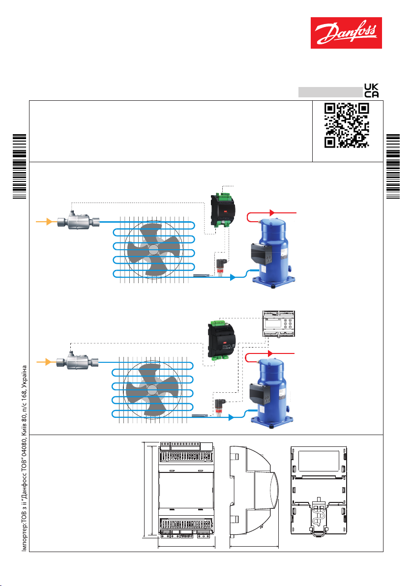
Applications
1. Superheat controller: standalone / network
ETS Colibri®
S2 Pe
Communication
Danfoss
Danfoss
64-3033.1
R64-3033.10
English
080R9345
More info
2. Valve driver
ETS Colibri®
Dimensions in mm
EKE 1D
Weight: 152 gram
© Danfoss | Climate Solutions | 2021.09
110
Reference signal
Reference signal
S2 Pe
CAN RJ
70 60
s
nf
64-3041.10
Danfoss
R64-3041.10
Danfoss
80G8215.11
AN325741271542en-000403 | 1
Info for UK customers only: Danfoss Ltd., 22 Wycombe End, HP9 1NB, GB
Page 2

Technical specications
POWER SUPPLY
EKE has galvanic isolation by switch-mode power supply.
24 V AC ± 20 %, 50/60 Hz. Maximum power consumption: 18 VA.
Input voltage rating (DC): 24 V DC ± 20%, 15 W.
I/O TYPE NUMBER SPECIFICATION
Max. 15 V input voltage
Do not connect voltage sources to unpowered units without limiting the
current to analog inputs (overall 80 mA).
Open circuit HW diagnostics available for voltage input on : AI4
AI3 (Pe)
Analog
inputs
Digital
inputs
Voltage 2
NTC 2
Auxiliary
Supplies
Voltage free
contacts
0 – 5 V ratiometric,
AI4
0 – 5 V , 0 – 10 V
AI1 (S3, S4), AI2 (S2)
NTC temperature probes, 10 kΩ at 25 °C
5 V +
1
Sensor supply: 5 V DC / 15 mA, overload protection approximately 150 mA
DI1, DI2
Steady current minimum 1mA
2
Cleaning current 100 mA at 15 V DC
On: RIL < = 300 Ω
O: RIH > = 3.5 k Ω
Digital
output
Stepper
motor
Battery
backup
Communication
© Danfoss | Climate Solutions | 2021.09
Relay 1
Bipolar /
unipolar
CAN
C1-NO1
Normally Open: 3 A General purpose, 250 V AC, 100 k cycle
Normally Open: 3 A Inductive (AC-15), 250 V AC, 100 k cycle
Normally Closed: 2 A General purpose, 250 V AC, 100 k cycle
Stepper valves: A1, A2, A3, A4
Bipolar and unipolar stepper motor output:
- Danfoss ETS / KVS / ETS C / KVS C / CCMT 2 – CCMT 42 / CTR Valves
(green, red, black, white)
1
1
1
1
- ETS6 / CCMT 0 / CCMT 1 (black, red, yellow, orange)
Other Valves:
- speed 10 – 400 pps
- drive mode 1/8 microstep
- max. peak phase current: 1.2 A (848 mA RMS)
- max. drive voltage 40 V
- max. output power 12 W
VB ATT : 18 – 24 V DC (24 V DC recommended):
– max. battery current: 850 mA at 18 V
– battery alarm will be activated below 16 V DC.
CAN - 3 way screw plug-in connector
No Built-in termination
CAN - RJ
RJ connector to directly connect and supply a MMI
No built in termination
AN325741271542en-000403 | 2
Page 3

Danfoss
n
fo
ss
G
General features and warnings
Plastic housing features
- DIN rail mounting complying with EN 50022
- Self-extinguishing V0 according to IEC 60695-11-10 and glowing/hot wire test at 960 °C according to IEC 60695-2-12
- Ball test: 125 °C according to IEC 60730-1. Leakage current: ≥ 250 V according to IEC 60112
Other features
- Operating conditions CE: -20T60, 90% RH non-condensing
- Storage conditions: -30T80, 90% RH non-condensing
- To be integrated in Class I and/or II appliances
- Index of protection: IP 20 on product and IP40 only on the front cover
- Period of electric stress across insulating parts: long
- Suitable for using in a normal pollution environment
- Category of resistance to heat and re: D
- Immunity against voltage surges: category II
- Software class and structure: class A
Ce compliance
This product is designed to comply with the following EU standards:
- Low voltage guideline: 2014/35/EU
- Electromagnetic compatibility EMC: 2014/30/EU and with the following norms:
- EN61000-6-1, EN61000-6-3 (immunity for residential, commercial and light-industrial environments)
- EN61000-6-2, EN61000-6-4 (immunity and emission standard for industrial environments)
- EN60730 (Automatic electrical controls for household and similar use)
General warnings
- Every use that is not described in this manual is considered incorrect and is not authorized by the manufacturer
- Verify that the installation and operating conditions of the device respect those specied in the
manual, especially concerning the supply voltage and environmental conditions
- This device contains live electrical components. All service and maintenance operations must therefore be
performed by qualied personnel
- The device must not be used as a safety device
- Liability for injury or damage caused by the incorrect use of the device lies solely with the user
Installation warnings
- Recommended mounting position: vertical
- Installation must comply with local standards and legislation
- Before working on the electrical connections, disconnect the device from the main power supply
- Before carrying out any maintenance operations on the device, disconnect all electrical connections
- For safety reasons the appliance must be tted inside an electrical panel with no live parts accessible
- Do not expose the device to continuous water sprays or to a relative humidity greater than 90%.
- Avoid exposure to corrosive or pollutant gases, natural elements, environments where explosives or mixes of
ammable gases are present, dust, strong vibrations or shock, large and rapid uctuations in ambient temperature
that might cause condensation in combination with high humidity, strong magnetic and/or radio interference
(e.g. transmitting antennae)
- When connecting loads be aware of the maximum current for each relay and connector
- Use cable ends suitable for the corresponding connectors. After tightening connector screws, tug the cables gently
to check their tightness
- Use appropriate data communication cables. Refer to the EKE data sheet for the kind of cable to be used and setup
recommendations
- Minimize the length of probe and digital input cables as much as possible, and avoid spiral routes around power
devices. Separate from inductive loads and power cables to avoid possible electromagnetic noises
- Avoid touching or nearly touching the electronic components tted on the board to avoid electrostatic discharges
Product warnings
• Use a class II category transformer for 24 V AC power supply.
• Connecting any EKE inputs to mains voltage will permanently damage the controller.
• Battery Backup terminals does not generate power to recharge a device connected.
• Batter y backup - the voltage will close the stepper motor valves if the controller loses its supply
voltage.
• Do not connect an external power supply to the digital input DI terminals to avoid damaging the
controller.
© Danfoss | Climate Solutions | 2021.09
320.10
80G320.10
80
AN325741271542en-000403 | 3
Page 4
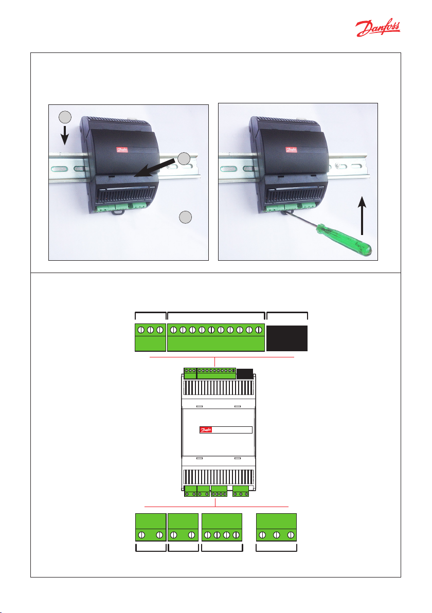
DIN rail mounting / demounting
The unit ca n be mounted onto a 35 mm DIN rail s imply by snapping it into p lace and securing it wi th a stopper to prevent
sliding.
It is demounted by gently p ulling the stirrup lo cated in the base of the h ousing.
1
2
Connection overview: EKE 1D
“Click”
L
H
3
ANALOG / DIGITAL INPUT
ANALOG / DIGITAL INPUT
COM
5V+
DI2
Danfoss
80G8287A.01
L
–/~
DI1
COM
5V+
DI2
DI1
H
GND
Superheat controller
Superheat controller
EKE 1D - 080G5360
+/~
GND
Bat+A1A2B1B2
GND
CAN - RJCAN
CAN RJ
COM
AI4
AI3
AI2
AI1
COM
CAN RJ
COM
AI4
AI3
AI2
AI1
COM
NO1C1NC1
© Danfoss | Climate Solutions | 2021.09
–/~
+/~
GND
Bat+A1A2B1B2
PWR 24V Vbat STEPPER VALVE DIGITAL OUTPUT
NO1C1NC1
DIGITAL OUTPUTSTEPPER VALVE
AN325741271542en-000403 | 4
Page 5
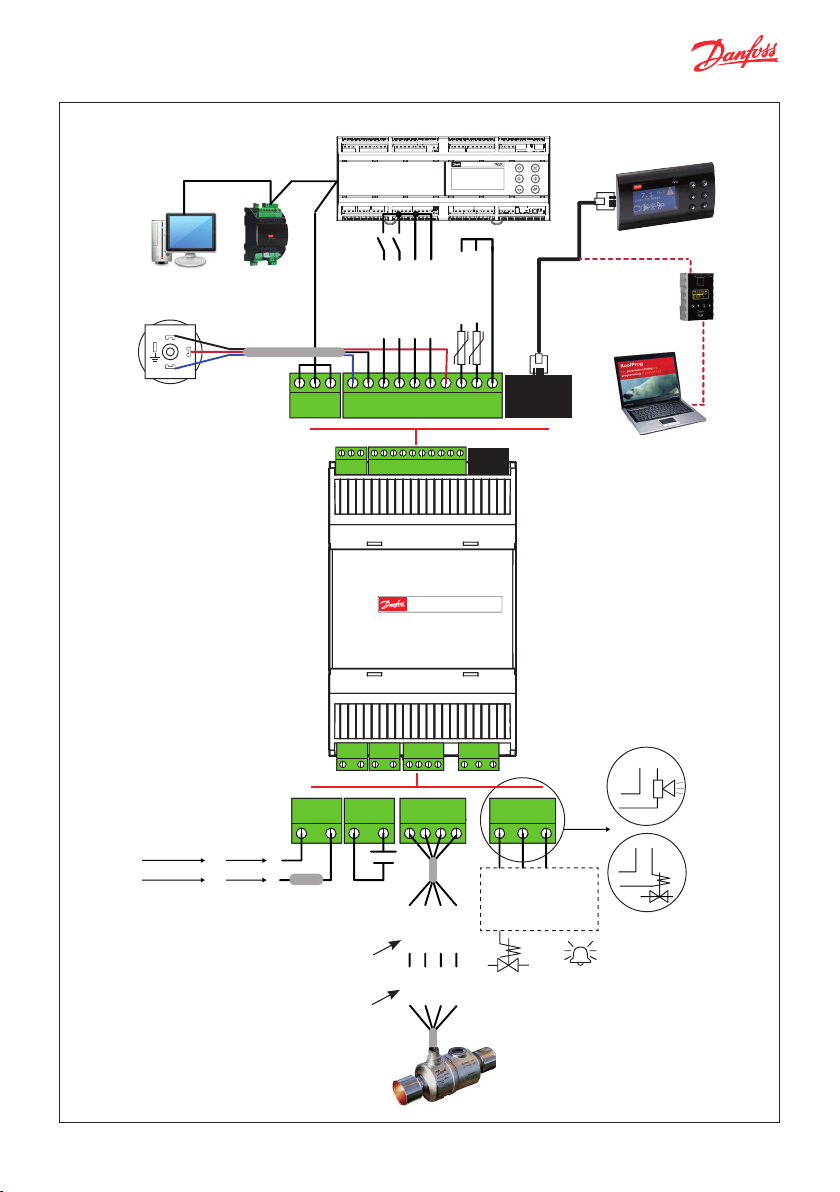
Connection overview, EKE 1D
CANBus
Master controller
MMIGRS2 Display
CAN RJ
080G0294 (optional)
Supervisor
network
1
3
2
Pressure transmitter
e.g. AKS 32R
Power supply
24 V AC
± 20%
–
+
EKE
AKS Cable
connection
060G1034
24 V DC
± 20%
LHGND
Danfoss
80G318.10
–/~
–/~
2.5 A
T fuse
(optional)
ETS6 valve
ETS / KVS
Colibri®
CCMT/CTR valves
CANBus
LHGND
–/~
–/~
+/~
+/~
backup
(optional)
COM
COM
GND
GND
+
18 V
Batt
5V+
5V+
Superheat controller
+/~
+/~
DI2
DI1 (ON/OFF)*
DI2
DI1
DI2
DI1
COM
5V+
DI2
COM
5V+
DI2
Superheat controller
EKE 1D - 080G5360
GND
Bat+A1A2B1B2
GND
Bat+A1A2B1B2
Bat+A1A2B1B2
Bat+A1A2B1B2
NTC (S2)
COM
AI4 (0 / 10 V)
COM
AI4
AI3
AI2
COM
AI4
AI3
AI2
DI1
COM
AI4
AI3
AI2
DI3
COM
DI1
COM
AI4
AI3
AI2
AI1
COM
NO1C1NC1
NO1C1NC1
red
black
yellow
orange
red
black
white
green
Optional
NTC (S3/S4)
CANBus
CAN RJ
CAN RJ
DI3
COM
AI1
COM
CAN RJ
CAN RJ
* Note: If Dl1(On/O) switch is not
used it must be short circuited
NO1C1NC1
NO1C1NC1
Relay
Normally open or
normally closed
(optional)
ON/OFF
solenoid
valve
080G0075 (opt.)
Alarm
MMIMYK
Gateway
Power
Power
KoolProg
PC tool
C1 NC1
C1 NO1
© Danfoss | Climate Solutions | 2021.09
AN325741271542en-000403 | 5
Page 6

Sensor mounting: Temperature sensor
1
1
Danfoss
60G496.11
Conductive
paste
Important Note
• Mount the sensor on a clean
paint-free surface.
• Remember to use heat
conducting paste and insulate
the sensor.
• For precise measurements,
mount the sensor max. 5 cm
from the outlet of the evaporator.
Evaporator outlet
Danfoss
84N365.11
Danfoss
84N403.10
3
Evaporator
Danfoss
84N366.12
Close to the
Close to the
evaporator
evaporator
2
/2 - 5/8 in.
OD
12 - 16 mm
3
/4 - 7/8 in.
OD
18 - 22 mm
1 - 1
OD
25 - 35 mm
1
OD
35 mm and higher
3
/8 in.
3
/8 in. and higher
Pressure transmitter
• Installation of the pressure transmitter is less critical. However, the pressure transmitter should be closer to
the temperature sensor, right after the evaporator and with its head upright. It is a good practice to select
a pressure transmitter with an average load of 40 - 60% of full scale.
• 5 EKEs at maximum are allowed to share the output signal of a ratiometric pressure transmitter.
In order to get a correct acquisition on all the units all the three wires (GND, 5 V and transmitter signal
output) must be routed to every unit.
Power supply
• Power sharing is allowed in EKE controller.
• It is a good practice not to reverse the polarity of the power connection cables.
Selection of the common power supply depends on the total number of sharings and the valve in use.
EKE EKE EKE
CAN RJ
D–D+RGND
COM
5V+
COM
5V+
CAN RJ
DI2
DI1
COM
AI4
AI3
AI2
DI3
COM
DI2
DI1
COM
AI4
AI3
AI2
DI3
COM
D–D+RGND
COM
5V+
COM
5V+
CAN RJ
CAN RJ
DI2
DI1
COM
AI4
AI3
AI2
DI3
COM
DI2
DI1
COM
AI4
AI3
AI2
DI3
COM
D–D+RGND
COM
5V+
COM
5V+
CAN RJ
CAN RJ
DI2
DI1
COM
AI4
AI3
AI2
DI3
COM
DI2
DI1
COM
AI4
AI3
AI2
DI3
COM
Danfoss
80G295.10
–/~
–/~
+/~
+/~
Superheat controller Superheat controller
Superheat controller
EKE 1x - 080G5xxx
–/~
+/~
GND
Bat+A1A2B1B2
–/~
+/~
GND
Bat+A1A2B1B2
Power supply
© Danfoss | Climate Solutions | 2021.09
NO1C1NC1
NO1C1NC1
Superheat controller
Superheat controller
EKE 1x - 080G5xxx
–/~
+/~
GND
Bat+A1A2B1B2
GND
Bat+A1A2B1B2
NO1C1NC1
NO1C1NC1
–/~
+/~
Superheat controller
EKE 1x - 080G5xxx
–/~
+/~
GND
Bat+A1A2B1B2
GND
Bat+A1A2B1B2
NO1C1NC1
NO1C1NC1
–/~
+/~
AN325741271542en-000403 | 6
Page 7

Danf
84N404.10
Relay Outputs
EKE 1D has 1 relay output:
• Ty pe SP DT relay. Digital Output can be used to connect either a solenoid valve or an alarm.
• The relays cannot be used for the direct connection of capacitive loads such as LEDs and ON/OFF control of
EC motors. All loads with a switch-mode power supply must be connected with a suitable contactor or similar.
Cable length
EKE controller supports the following max. cable length.
Cable length Wire size min. / max.
[m] [m2]
Analog inputs (Current/Voltage) max. 10 0.14 / 1.5
Temperature sensor max. 10 *) –
Stepper valve connection max. 30 0.14 / 1.5
Power supply max. 5 0.2 / 2.5
Digital input max. 10 0.14 / 1.5
Digital output – 0.2 / 2.5
Digital MMI max. 3 over CAN RJ –
Communication bus max. 1000 0.14 / 1.5
Cable and wiring *)
• The max. cable distance between the controller and the valve depends on many factors like shielded/
unshielded cable, the wire size used in the cable, the output power for the controller and EMC.
• Keep controller and sensor wiring well separated from mains wiring.
• Connecting sensors by wires more than the specied length may decrease the accuracy of measured values.
Warning
Separate the sensor and digital input cables as much as possible (at least 10 cm) from the power cables to the
loads to avoid possible electromagnetic disturbance. Never lay power cables and probe cables in the same
conduits (including those in the electrical panels).
Connecting CANbus
• For the CANbus cable, it is best to use 24 AWG shielded twisted-pair cable with a shunt capacitance
of 16 pF/ft and 100 Ω impedance.
• The controller provides a communication interface which is connected to the RJ and CAN terminals
(see connection overview).
• Terminal resistors 120 Ω for terminal devices are recommended at both ends of the bus, Terminal
resistance between H and L terminals.
• The default unit address is 1, which can be changed using parameter “G001 Controller adr".
© Danfoss | Climate Solutions | 2021.09
CANbus
H
L
Not in use
oss
Gnd
AN325741271542en-000403 | 7
Page 8

Stepper Motor Output
• All valves are driven in a bipolar mode with a 24 V supply chopped to control the current (Current driver).
• The stepper motor is connected to the “Stepper Valve” terminals (see terminal assignment) with a standard M12
connection cable.
• To congure stepper motor valves other than Danfoss stepper motor valves, the correct valve parameters must
be set as described in the Valve conguration section (see manual for details).
• The default valve setting in EKE 1D is: none.
• The correct valve must be dened in “Valve conguration”, i.e. parameter I067. An overview of valve types is
given in the “Parameter identication” section.
Valve Cable Connec tion
ETS Colibri / KVS Colibri/ ETS / KVS / CCM / CCMT / CTR
Danfoss M12 Cable White Black Red Green
ETS / KVS / CCM Pins 3 4 1 2
ETS Colibri® / KVS Colibri / CCMT / CTR / Pins A1 A2 B1 B2
EKE terminals A1 A2 B1 B2
Pin designation used in above table are shown in the product data sheet.
ETS 6
Wire color Orange Yel low Red Black Gray
EKE terminals A1 A2 B1 B2 Not connected
Guideline for long M12 cables on Danfoss stepper motor valves
• Long cables will lead to degradation of performance.
• You can overcome this degradation by changing the settings for the valve driver. This guideline is based on
the cable t ype being the same t ype as the standard Danfoss stepper motor cable.
Recommended wire size and cable distance bet ween EKE controller and stepper motor valve
Cable length 1 m – 15 m 15 m – 30 m 30 m – 50 m
Wire diameter
0.52 / 0.33 mm
(20 / 22 AWG)
2
0.33 mm
(20 AWG)
2
0.82 mm
2
(18 AWG)
Parameter setting for long M12 cable
Product
ETS 12C - ETS 100C
KVS 2C - KVS 5C
0 m – 15 m cable 15 m – 30 m cable 30 m – 50 m cable
Use default values
ETS 12.5 - ETS 400
KVS 15 - KVS 42
CTR 20
Use default values
CCMT 2 - CCMT 8
CCM 10 - CCMT 40
ETS 6 Use default values
CCMT 0 Use default values
CCMT 1 Use default values
CCMT 16 - CCMT 42 Use default values
© Danfoss | Climate Solutions | 2021.09
Update following parameter
I028 Valve drive current=
925 mA peak
I028 Valve drive current=
200 mA peak
I028 Valve drive current=
270 mA peak
I028 Valve drive current=
270 mA peak
I028 Valve drive current=
400 mA peak
I028 Valve drive current=
450 mA peak
I028 Valve drive current = 1000 mA peak
I065 Valve duty cycle = 90%
I028 Valve drive current= 300 mA peak
I028 Valve drive current= 350 mA peak
I028 Valve drive current= 350mA peak
I028 Valve drive current= 500 mA peak
I028 Valve drive current= 500 mA peak
AN325741271542en-000403 | 8
Page 9

LED indication
(A) Two status LEDs to indicate operational status
• Steady green = power ON
• Flashing green = data transmission / initialization
• Flashing red = alarm / error condition
(B) Two status LEDs to indicate valve operation
• Flashing red = valve closing
• Steady red = valve fully closed
(A)
(B)
• Flashing green = valve opening
• Steady green = valve fully open
• Both green and red ashing = valve-related alarm
User interface
EKE 1D can be setup using one of the following user interfaces:
1. Danfoss KoolProg soft ware
2. Danfoss MMIGRS2 external display
3. Communication bus: CANbus
KoolProg
KoolProg is a software tool for quickly and easily conguring EKE controllers. It enables you
to make online changes to parameter conguration, copy settings to multiple controllers,
monitor the live status of input/outputs, and quickly analyze controller behavior and
program patterns with a graphical trending tool.
KoolProg Software is available for download free of charge at http://koolprog.danfoss.com.
KoolProg requires a Gateway (code 080G0073) to connect to the PC.
CANRJ
EKE
Power supply
Danfoss
80G296B.10
Gateway
Cable holder
USB
Important note!
To guarantee a reliable USB connection to a host device (e.g. industrial PC), you must:
• Connect terminals R and H on MMIMYK CAN port using a termination wire.
• Place cable holder close to MMIMYK to keep USB connector rmly in place.
• Keep USB cable length < 1 m.
• Place MMIMYK and route USB cable far from noise sources (inver ter, motors, contactors etc.)
© Danfoss | Climate Solutions | 2021.09
AN325741271542en-000403 | 9
Page 10

ACCCBI080G0075
Danfoss MMIGRS2 display
Connecting external MMIGRS2 display
MMIGRS2 display can be used to set up EKE 1D. The display
can be used not only for setting up the necessary parameters, but also as an ex ternal display during operation to
show impor tant parameters, e.g. degree of opening of
valve, superheat, etc.
Important note:
• Max. distance bet ween controller and display is
3 m over CAN RJ.
• CANbus requires termination in both ends of the cable
by a 120 Ohm resistor to ensure reliable communication.
On EKE 1D terminate L and H with resistor and on
MMIGRS2 terminate R and H with jumper.
• External power for MMIGRS2 is not needed while using
CAN RJ connector. In case of connecting via 3 way screw
plug-in connector external power supply is required for
MMIGRS2.
MMIGRS2 (Back view)
COM
–/~
+/~
GND
–/~
+/~
GND
5V+
DI2
DI1
COM
AI4
AI3
AI2
DI3
COM
Superheat controller
Superheat controller
EKE 1D - 080G5360
Bat+A1A2B1B2
Bat+A1A2B1B2
CAN RJCAN RJ
NO1C1NC1
NO1C1NC1
CAN RJ
MMIGRS2
Danfoss
80G319.10
For cable <3 meter
RJ CAN connector
Termination Jumper
between R and H
Danfoss
34G306.11
For cable >3 meter (only EKE 1C and EKE 1D)
2-way screen connector for power supply
4-way screen connector for CANbus network
MMIGRS2 (Front view)
Controller name
Primary readout
Operating status
Evap. temperature
Evap. pressure
Valve OD
Note: Setup and ser vice menu requires login with the default password 100 ( daily use),
200 (service use) or 300 (commissioning use). Long press Enter key to access login menu.
© Danfoss | Climate Solutions | 2021.09
Homescreen
UP
Escape/cancel
Right
Left
Enter
Down
Navigation help
Alarm indicator
Reference point
S2 – S4
Media
Temperature
AN325741271542en-000403 | 10
Page 11

Setup wizard via MMIGRS2 display
When all connections to the controller have been made, af ter the power is switched on, the Danfoss logo will appear
for 5 seconds, then the Home screen will be displayed.
To access the Wizard: press and hold enter to access the Login screen, the commissioning password is 300, scroll down
the Setup and service menu and select “Setup wizard”.
The Wizard workow is: a. Language selection; b. Application selection; c. Input conguration; and d.
Output conguration.
When using the Setup Wizard, repeat the following sequence for all parameter settings:
a. From Setup wizard, select relevant parameters.
b. Press ENTER to highlight 1st option
c. Scroll with UP / DOWN to your desired option
d. If the selected default value is acceptable, press DOWN to get to the next settings. Other wise,
press ENTER to set your choice
e. Scroll with DOWN to the next parameter (repeat sequence a. to e.)
Note:
• If you do not have sucient information to complete the Wizard, leave settings on their default values. To generate
the requested info, you can use Danfoss Coolselector2 software to calculate operating conditions and valve OD for the
same operating point.
• Setup Wizard only covers the most important parameters. If other features are to be enabled
(e.g. Alarm settings, MOP/LOP, etc.), they must be congured separately once the Setup Wizard is done.
Setup Wizard is also available in KoolProg PC tool.
The workow process is the same as that described above for MMIGRS2 display.
For details, pl ease refer to EKE data sheet.
1
1
Power on
2
2
Press and
hold enter
Status menu
QR code
Controller info
Detailed status
SH trend 25 mi n
Display
Home menu
© Danfoss | Climate Solutions | 2021.09
3
3
Commissioning 300
Danfoss
Danfoss
80G294.20
80G294.20
Login
PW:
Service 200
Daily 100
5
5
Esc
Setup and service
Reference
Control
Defrost
Alarm conguration
IO cong
Display
Communication
Service
Setup wizard
Controller name
AN325741271542en-000403 | 11
4
4
Page 12

Quick guide for parameter selection
Apart from wizard setup, users can also use the following section which describes quick parameter settings for general
applications.
Driver Controller
Start : Main switch= O
Selec t valve type
Application mode
Driver- Controller
Analog signal type e.g
1 - 5 V / 0 - 10 V
EKE 1D Parameters
Driver reference
conguration
Ext .ref.
voltage,low
Ext .ref.
voltage,high
Ext .ref.
current,low
Ext .ref.
current,high
I091
I034
I035
–
–
Select Refrigerant
Select Temperature sensor
Select Pressure transmitter
Dene Min/Max Pressure
Select Superheat Control
Set Min/Max Ref value
Make sure that main switch is OFF before changin g
the settings. Th e setting will dep end on the system
requirement.
Parameter: R012 Main Switch
Selec t predened Danfoss valve type ETS, ETS C, K VS,
KVS C, CCM , CCMT, CTR, o r user dened.
Parameter: I067 Valve conguration
Selec t how you want to use EKE: dri ver or superheat
controller.
Parameter: R102 Operation mode
Select the predened refrigerant .
Parameter: O030 Refrigerant
Selec t Temperatur e sensor type: EK S, ACCPBT, MBT,
Sensata 112CP, Bus shared
Parameter: I081 - S2 sensor conguration.
Check parameter list for other sensors.
Selec t Pressure transmitter typ e –AKS 32R, Sensata
112CP, OEM Ratio, NSK, AKS 32 1 - 5 V,
OEM Voltage, Bus shared
Parameter: I085 - Pe transmitter conguration.
Check parameter list for other sensors.
Dene min and max Pressure transm itter in barg.
Parameter: O020 - Pe min., O 021 Pe max., Check
parameter list for other sensors.
Selec t application control type SH control. 1: MSS,
2: LoadAp, 3: Fixed, 4: Del ta SH.
Parameter: N021 SH reference mode.
Set the value for the selected control m in./max.
superheat reference.
Parameter N009 SH max., N 010 - SH min.
Selec t Other features
Finish: main switch = ON
© Danfoss | Climate Solutions | 2021.09
Dl1= ON
Optional – Force star t up, MOP, LOP, Alarm,
Thermostat function.
Check par ameter list for details.
Remember to turn on main switch to s tart ‘ON’ .
Parameter R012 Main switch.
ON=Regulation start
Parameter O002: 0 = Bus->Start /Stop | 1 = Main Switch
IF Dl1 is not use d make a short circuit w ith a wire
betwe en Dl1 and COM.
AN325741271542en-000403 | 12
Page 13

EKE 1D – Commonly used parameter identication
If the parameter value is outside the range, controller will not detect error.
Parameter CA N
R012 Main switch 550B B8 0 0 = regulati on O | 1 = regulation On
R102 Operation mode 550B B9 0 0 = Supe rheat control | 1 = Valve driver
O002 Dl1 conguration 550C 1C 1 0 = Bus->Start/Stop | 1 = Main Switch
I091 Driver reference
conguration
I034 Ex t ref. voltage low 550C 39 0 Ra nge 0 – 10 V. To be used with l 091
I035 Ex t ref. voltage high 550 C 38 10 Range 0 – 10 V. To be used with l0 91
I067 Valve conguration 550C 3B 0
O030 Refrigerant 550B C8 0
I081 S2 sensor
conguration
I083 S3 sens or
conguration
I084 S4 sensor
conguration
I085 Pe transmitter
conguration
O020 Pe transmitter min.
(in bar g)
O021 Pe transmitter max.
(in bar g)
CAN
Index
Subindex
550C D1 0 0 = Voltage to OD | 1 = Bus to OD | 2 = Bus to steps
550C C1 0
550C BF 0
550C BD 0
550C C5 0
550C 2A
550C 2B
De-
Description
fault
0 = no valve, 1 = Use rDef
2 = ETS 12C, 3 = ETS 24C , 4 = ETS 25C, 5 = ETS 50C , 6 = ETC 100C
7 = ETS 6, 8 = ETS 12.5, 9 = ETS 25, 10 = ETS 50, 11 = ETS 100,
12 = ETS 2 50, 13 = ETS 400
14 = KVS 2C , 15 Імпорт ер:ТОВ з іі “Данфо сс ТОВ” 04080, Ки їв 80,
п/с 168, Україн а = KVS 3C, 16 = KVS 5C
17 = KV S 15, 18 = KVS 42
19 = CCMT 0, 20 = CCMT 1
21 = CCMT 2, 22 = CCMT 4, 23 = CCMT 8, 24 = CCMT 16, 25 = CCMT 24,
26 = CCMT 30, 27 = CCMT 42
28 = CCM 10, 29 = CCM 20, 30 = CCM 30, 31 = CCM 40
32 = CTR 20
0 = Undef 10 = R503 20 = R407C 30 = R417A 40 = 448A
1 = R12 11 = R114 21 = R407A 31 = R422A 41 = 449A
2 = R22 12 = R142b 22 = R407B 32 = R413A 42 = 452A
3 = R134A 13 = R User 23 = R410A 33 = R422D 43 = R450A
4 = R502 14 = R32 24 = R170 34 = 427A 44 = R452B
5 = R717 15 = R227 25 = R290 35 = R438A 45 = R454B
6 = R13 16 = R401A 26 = R600 36 = R513A 46 = R1233zdE
7 = R13b1 17 = R507 27 = R600a 37 = R407F 47 = R1234zeZ
8 = R23 18 = R402A 28 = R744 38 = R1234ze 48 = R449B
9 = R500 19 = R404A 29 = R1270 39 = R1234yf 49 = R407H
0 = Not dene d | 1 = EKS 221 | 2 = ACCPBT NTC10K | 3 = MBT 153 10K |
4 = 112CP | 5 = Bus Shared
0 = Not dene d | 1 = EKS 221 | 2 = ACCPBT NTC10K | 3 = MBT 153 10K |
4 = 112CP | 5 = Bus Shared
0 = Not dene d | 1 = EKS 221 | 2 = ACCPBT NTC10K | 3 = MBT 153 10K |
4 = 112CP | 5 = Bus Shared
0 = Not dene d | 1 = AKS 32R | 2 = ACCPBP Ratio | 3 = 112CP | 4 = OEM Ratio|
5 = NSK | 6 = AKS 32 1-5V | 7 = OEM Volt age | 8 = Bus shared
-1 Dene pressure range in bar gauge
12 Den e pressure range in bar g auge
N021 SH reference mode 550B D2 2 0 = Fixed SH | 1 = Loadap | 2 = MSS | 3 = Delta temp
N107 SH xed setpoint ( K) 550B D3 7 Ra nge 2 – 40 K
N009 SH max. ( K) 550B D4 9 Range 4 – 40 K
N010 SH mi n. ( K) 550B D5 4 Range 2 – 9 K
N116 SH ref. delta tem p.
factor ( %)
For a detailed p arameter list and expla nation, please check the EK E data sheet.
© Danfoss | Climate Solutions | 2021.09
550B DA 65 Range 20 – 100
AN325741271542en-000403 | 13
Page 14

For your own notes
© Danfoss | Climate Solutions | 2021.09
AN325741271542en-000403 | 14
Page 15

Related products
MMIGRS2 Display Power Supply MMIMYK Gateway
User interface module MMIGRS2 Display AK-PS
Pressure Transducer Temperature Sensor Backup power module
AKS Pressure Tranducer
Available with ratiometric and 4 – 20 mA.
NSK
Ratiometric pressure probe
XSK
Pressure probe 4 – 20 mA
ACCCBI Cable Stepper motor valves M12 cable
Input: 100 – 240 V AC, 45 – 65 Hz
Output: 24 V DC: available with 18 VA, 36
VA and 60 VA
ACCTRD
Input: 230 V AC, 50 – 60 Hz
Output: 24 V AC, available with 12 VA,
22 VA and 35 VA
PT 1000
AKS is a High precision temp. sensor
AKS 11 (preferred), AKS 12, AKS 21
ACCPBT PT1000
NTC sensors
EKS 221 ( NTC-10 Kohm) MBT 153
ACCPBT
NTC Temp probe (IP 67 /68)
MMIMYK device is used as a gateway
to connect EKEs and the PC tool i.e
KoolProg software for parameter
setting or data logging.
EKE 2U Backup power module can
provide enough energy during
power failure to the stepper
controller to ensure closure of the
electronic valves.
ACCCBI cables for MMI display and gateway. EKE is compatible with Danfoss stepper
motor valves i.e Danfoss ETS 6, ETS, KVS,
ETS Colibri®, KVS colibri®, CTR, CCMT
© Danfoss | Climate Solutions | 2021.09
M12 Angle cable to connect
Danfoss stepper motor valve and
EKE controller
AN325741271542en-000403 | 15
 Loading...