

Page 1

Data Sheet
Superheat controller
Type EKE 1A, 1B, 1C, 1D (PV04)
For commercial air conditioning and refrigeration applications
The exible pre-programmed EKE superheat
controller from Danfoss provides ultimate
software control, allowing you to tailor the
performance of your system to your exact
requirements. EKE is ideal for controlling a wide
range of commercial air conditioning and
refrigeration applications, such control helps
you to achieve the highest eciency in the
system reducing the operational cost by up to
20% with minimal eort. EKE is generally used
where there is a requirement for accurate
control of superheat or temperature control in
connection with air conditioning and
refrigeration. The superheat is regulated to the
lowest possible value within a short period of
time. It regulates the superheat of the
evaporator by charging optimally even when
there are great variations of load resulting in
reduction of energy consumption and
operational cost
Typical Applications:
• Chillers
• Processing plant / Cabinet cooling
• Cold store (air coolers)
• A/C plant / Air conditioning
• Heat pumps. Residential Heat Pump
• Transport cooling
• Stepper Motor Driver
AI197986442906en-000501
Page 2

Features
EKE 1A
EKE 1B
EKE 1C
EKE 1D
Power supply:
Power Supply Type
24 V AC / DC ± 20%••••
Battery Backup input
18-24 V DC••••
Class of insulation
Class II
Data communication
MODBus
RS 485 RTU••
Wired CANbus
(4 wires)
(3 wires)
CANbus RJ 12
Danfoss MMI service port
•••
•
Inputs::
Number of temperature
sensors
123
2
Temperature sensor types
PT1000
•
NTC 10K, type EKS••••
NTC 10K, type ACCPBT
•••
•
NTC 10K, type Sensata
•••
•
Number of Pressure sensor
112*
1
Pressure Transmitter
types
Ratiometric 0.5 - 4.5 V
•••
•
Voltage signal 0 – 10 V
•••
•
Current signal 0 – 20 mA
•
Share Pressure Signal
Hardware (Up to 5 devices)
•••
Via wired CANbus (not
possible to share ratiometric sensor)
•
•
Via MODbus••
Number of external references
111
1
External reference
0-20mA
•
User dened current
•
0-10V
•••
•
0- 5V
•••
•
User dened voltage( max
10V)
•••
•
Digital input Dry contact
3
2
Outputs
Digital output
1
Relay
Normally Open
3A General purpose, 250V ac, 100k
Normally closed
2A General purpose, 250V ac, 100k
Relay Function
Alarm relay or LLSV (Liquid Line Solenoid Valve)
User interfaces
Koolprog Software tool
•••
•
MMIGRS2 screen••••
Master controller••
•
Superheat controller, Type EKE 1A, 1B, 1C, 1D
Portfolio overview
Table 1: Portfolio overview
*The 2nd pressure sensor is mounted on AI4
© Danfoss | Climate Solutions | 2022.02 AI197986442906en-000501 | 2
Page 3
Red constant
Green constant
Flashing red
Flashing green
Flashing red and green
Hardware functions
Digital inputs
Used to interact with the EKE for systems where the EKE is not connected to a system controller via data communication.
The available digital inputs DI can be used for the following functions:
a. Injection control ON/OFF(DI1). b. Defrost sequence (DI2). c. Heating and cooling selection mode (DI2) d. Preset OD
(DI2)
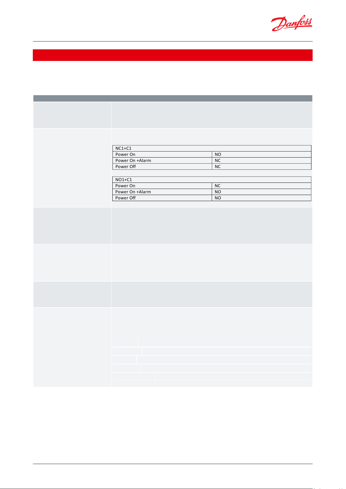
Digital Output (Relay)
• The relay for the liquid line solenoid valve will operate when refrigeration is required
• The contact of the relay is closed in alarm situations and when the controller is de-energized.
• The digital output DO1 O013 can be congured for solenoid valve, max capacity or for alarm function.
NC1+C1
Power On
NO
Power On +Alarm
NC
Power Off
NC
NO1+C1
Power On
NC
Power On +Alarm
NO
Power Off
NO
Handling power failure
For safety reasons the liquid ow to the evaporator must be cut o in case of power failure. The valve’s stepper Motor
will remain open in power failure situation
There are two ways of coping with this situation
One of the following two solutions can be applied in the system
• Mounting of a solenoid valve in front of EEV (using LLSV relay signal from EKE)
• Mounting of a battery backup for EEV valve (Use Danfoss EKE 2U)
Analog Inputs
External Reference Signal:
Used for:
• Driving the stepper motor valve to a desired opening degree (Driver Mode)
• Displacing temperature reference, superheat reference or max OD
The voltage signal e.g., 0 – 10 V can be used in all EKE controllers whereas current signal e.g 0 – 20 mA signal is only
available in EKE 1C
Communication: RS485 Modbus / CANbus
The controller can be provided with data communication for connecting to other devices in the systems.
In this case, monitoring and data collection can be performed from one device i.e., PLC – which will be benecial for
the diagnostic or during the installation processes.
For example, it is possible to substitute the physical sensors of the EKE controller by writing sensor values via Bus. The
frequency of update should be according to the Modbus maximum update interval G004 (Refer to parameter list)
Light-emitting diodes (LEDs)
Two sets of light-emitting diodes make it possible to follow the operation status of the valve and the controller. They
indicate the following
• Power/data transmission and Alarm/Error indication
• Stepper valve operational status
LED status:
valve is closed
valve is fully open
valve is moving in close direction
valve is moving in open direction
Error
Superheat controller, Type EKE 1A, 1B, 1C, 1D
Functions
The EKE 1x products supports a wide range of functionalities illustrated in table 3 and 4. Check the user guide for
more detail about congurations and other detailed options.
Table 2: Hardware functions
© Danfoss | Climate Solutions | 2022.02 AI197986442906en-000501 | 3
Page 4

Valve Driver
The EKE controls the opening degree of the valve, the control signal can be an analog signal or a value via communication bus
Superheat Reference Calculation
• Fixed Superheat The controller keep the superheat at a xed reference value determined by the user. SH xed setpoint
can be varied according to the need of application.
• Minimum Stable Superheat (MSS): The superheat control algorithm will attempt to regulate the superheat down to
the lowest stable value between the minimum superheat setting, “Min SH” and the maximum superheat setting, “Max.
SH”.
• LoadAP Superheat LoadAP is a kind of preprogrammed MSS curve. In Load ap application, SH reference follows a
dened curve as shown in the diagram. This two-point curve is dened by SH max and SH min, this method will give a
robust SH reference and can in many cases be the best t for systems.
• Delta temp. superheat SH reference is calculated as a ratio between the media temperature and evaporator temperature. This reference mode is only possible if media temperature (S3) sensor is available and if the system uses n and tube
evaporator.
Temperature Control *
EKE has a feature to regulate the temperature control. This can be done with either
• Thermostat cut in/cut out function: if temperature is above the set point + dierential, cooling is started with maximum cooling capacity. In maximum capacity superheat is controlled to be on superheat set point. Cooling is active until
the temperature is below set point.
• Modulating Thermostat (MTR): When temperature is getting close to the MTR reference the cooling capacity gradually
reduce so that the temperature can be stable on the MTR reference and the superheat will be oating.
Protection Functions
• Failsafe operation: During operation if sensors error occurs, the valve position can be set to full close, xed
opening degree or average calculated OD as required.
• Superheat close: When the superheat is below a set minimum value, the valve will close faster to protect the compressor from the risk of getting liquid in the suction line and bring the superheat back to superheat reference.
• Maximum Operating Pressure (MOP): To reduce the strain on the compressor, a maximum operating pressure is set. If
the pressure comes above this limit the controller will control the valve to provide a lower pressure instead of a low superheat.
• Low Operating Pressure (LOP): known as Cold start feature, it allows applications such as heat pumps to operate at
lower ambient conditions to prevent compressor from stopping due to low suction pressure in the startup phase.
• High Condensing temperature protection (HCTP)**: High condensing temperature protection will make sure that
the load on the condenser is reduced in case a too high condensing temperature is reached. This is done by limiting the
valve opening degree.
• Minimum S4/leaving media (freeze protection) *: Lowers the ow in the expansion valve if temperature of leaving
media out of the evaporator is below a minimum value set by the user.
Other Functions
• Fast Start up: Quickly open an EEV valve when compressor turns ON to prevent too low suction pressure as well as for
faster stabilization of superheat or temperature set point. This can be ensured by setting either P-control, Start opening
degree with protection or Fixed opening degree without protection. This start up condition is kept until the start time
expire or superheat reaches at setpoint.
• Defrost sequence: The controller does not itself handle defrost of the evaporator. It is however possible to enter a special defrost sequence which will overrule the normal control of the valve.
• Manual control: The valve can be controlled manually by setting the desired opening degree via Analog signal or communication bus used for commissioning purpose. A special service mode is also available for service and testing purpose.
• Service mode: Service mode is designed to provide a very simple way of operating the valve for diagnostic and service
purpose. There is neither application nor protection in this mode. The user can open and close the valve using simple
button presses on MMIGRS2.
Superheat controller, Type EKE 1A, 1B, 1C, 1D
Table 3: Control Functions
*Not available in EKE 1A
**Only Available EKE 1C
© Danfoss | Climate Solutions | 2022.02 AI197986442906en-000501 | 4
Page 5
Danfoss
80G8221.01
EEV
TT
Pe
S2
Battery
Optional connection
Alarm indication
Normal close
Mandatory connection
ON/OFF signal
Modbus or Analog signal
Power 24 V AC / 24 V DC
EKE controller (in driver mode)
MASTER controller
Superheat controller, Type EKE 1A, 1B, 1C, 1D
Applications
EKE series devices are used where precise control of superheat in air conditioning system is needed. It helps
achieving high energy eciency and reliable operation
EKE serves 2 main applications:
• Driver Mode
• Controller Mode
1.
Superheat controller
2.
Temperature controller
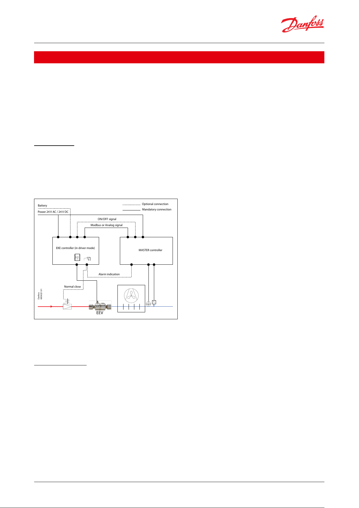
Driver mode
Driver Mode:A master is commanding the valve open degree to the EKE controller. The control signal can be fed for
example by:
• Analog signal e.g., 0 – 10 V, a 4 – 20 mA
• Bus communication via RS485 (Modbus RTU).
Figure 1: EKE as Driver Mode
NOTE:
'Normal closed' valve in front of EEV is optional alternative to a battery backup solution which closes the EEV in case
of power fail. The Digital output can also be used as alarm indication to the master controller. The Master can send a
start signal to EKE DI terminals
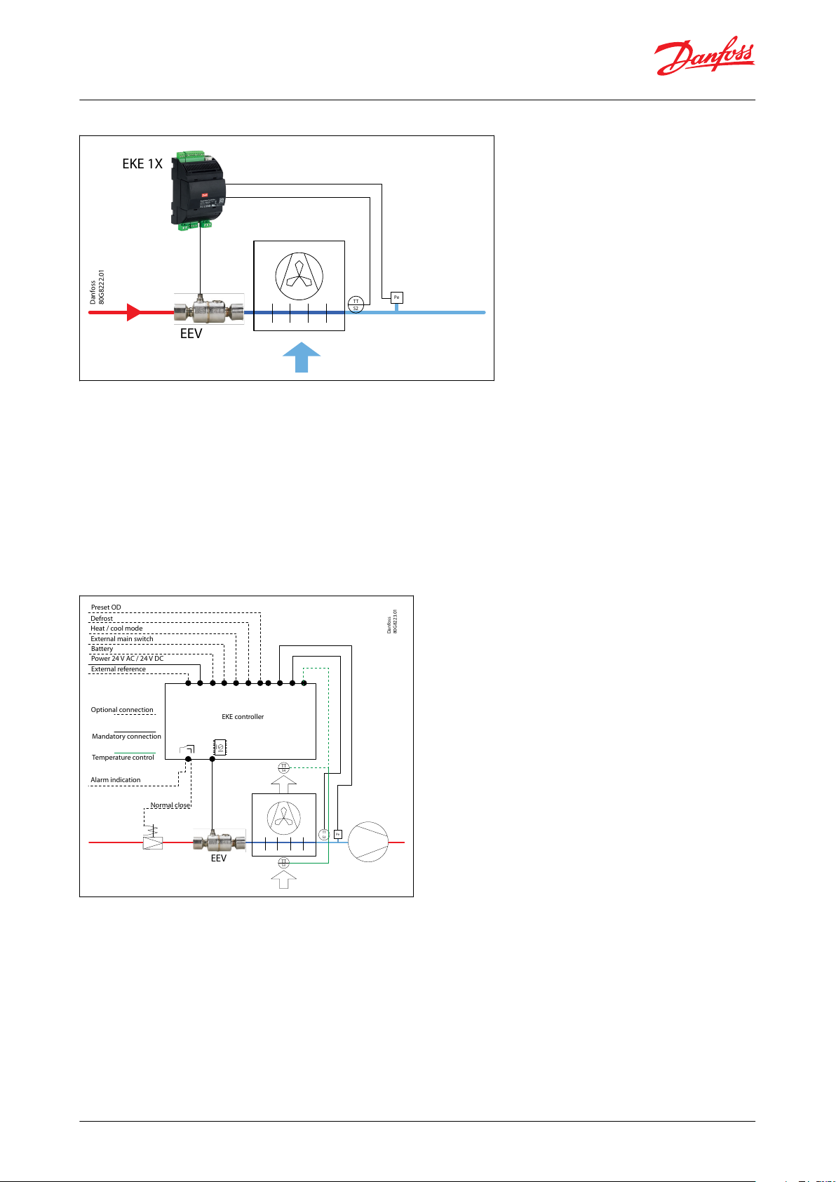
Controller Mode
Controller Mode:
Superheat Control: EKE can serve as a PI controller that controls the superheat of the evaporator based on a
pressure Pe and temperature (S2) sensors. In superheat mode the controller will control the superheat to be stable
and close to the superheat reference. If superheat is too low the ow in the expansion is decreased and superheat
will be higher
© Danfoss | Climate Solutions | 2022.02 AI197986442906en-000501 | 5
Page 6
Danfoss
80G8222.01
TT
S2
EEV
EKE 1X
Pe
Danfoss
80G8223.01
EEV
EKE controller
Preset OD
Defrost
Heat / cool mode
Battery
Power 24 V AC / 24 V DC
External reference
Optional connection
Mandatory connection
Temperature control
Alarm indication
Normal close
External main switch
TT
S4
Pe
TT
S2
TT
S3
Superheat controller, Type EKE 1A, 1B, 1C, 1D
Figure 2: Superheat control application
Temperature controller The temperature control is an ON/OFF thermostat that opens/closes the stepper valve or
modulating thermostat that regulates temperature more smoothly following a temperature reference point. The
temperature control can be accomplished via a signal from temperature sensor S3 placed in the air ow before the
evaporator or S4 placed in the air ow after the evaporator.
EKE has 2 methods of controlling temperature:
• ON/OFF thermostat
• Modulating thermostat (MTR)
The need for cooling can either be dened by the incoming media (S3) or the outgoing media (S4) temperature
Figure 3: Temperature control application
NOTE:
EKE1A can only work in the driver mode or superheat control mode as it supports only one temperature sensor
input
© Danfoss | Climate Solutions | 2022.02 AI197986442906en-000501 | 6
Page 7

Feature
Description
Power supply
Galvanic isolation by switch mode power supply
Input voltage rating (AC): 24 V AC ± 20 % (min.19.2 V AC - max. 28.8 V AC
Input frequency (AC): 50 / 60 Hz
Input voltage rating (DC): 24 V DC (min. 20 - max. 40 V DC)
Provides 5 W at 5 V and 15 V outputs isolated from the 24 V input
Insulation between power supply and the extra-low voltage.
Class of insulation Class II
Power Consumption
Total Power consumption with following valve in operation and MMIGRS2 connected to the controller:
CCMT 16 - CCMT 42: 15VA/10W
ETS 6: 11 VA / 7.5W
ETS 12C - ETS 100C: 20VA / 14W
KVS C: 20VA / 14W
ETS 12.5 - ETS 400 7 VA / 5W
CCMT 2 - CCMT 8 7 VA / 5W
CTR 20: 7 VA / 5W
Plastic Housing
• DIN rail mounting complying with EN 50022
• Self-extinguishing V0 according to IEC 60695-11-10 and glowing / hot wire
test at 960 °C according to IEC 60695-2-12
• Material used for Enclosure are UL94-V0 and RoHS compliant
• Ball test: 125 °C according to IEC 60730-1
• Leakage current: ≥ 250 V according to IEC 60112
Connectors
• Plug able Screw connector Pitch 3.5 mm, relay and power connector Pitch 5
mm, CAN MMI: Modular Jack 6P4C
• Material used for connectors are RoHS and UL approved
Feature
Type
Description
Protection
Short circuit
Motor driver: dissipative over current protection
Over voltage
Analog input: current limit and internal clamp diode
Digital input: current limit and internal clamp diode
Communication: transceiver IC
Over Temperature
Motor driver: thermal shutdown at 150 °C
Unstable Digital Input
Continuous variation of the digital input state
I/O
Type
Specications
Analog inputs
• Max. 15 V input voltage
• Open circuit HW diagnostics available for voltage input on: AI3, AI4
(EKE 1C) AI4 (EKE 1A and EKE 1B).
WARNING:
Do not connect voltage sources without current limitation (overall 80
mA) to analog inputs while unit is not powered.
0 – 5 V
EKE 1C (AI3, AI4) and EKE1A/1B/1D AI3 | Accuracy ± 40 mV, resolution 1.2
mV.
0 – 10 V
EKE 1C (AI3, AI4) and EKE1A/1B/1D AI3 | Accuracy ± 50 mV, resolution 2.5
mV.
0 – 20 mA (EKE 1C only)
Accuracy ± 100 μA, resolution 10 μA.
Input resistance: <100 Ω
NTC Sensor
NTC temperature probes: 10 kΩ at 25 °C range: 300 kΩ to 100 Ω
Accuracy: 50 – 120 °C: 1.5 K, -40 – 50 °C: 0.4 K, 0 °C: 0.2 K
Resolution: ≤ 0.1 K, ≤ 0.3 K (EKC 1C, AI5)
Pt1000 sensor
Range: 723 Ω to 1684 Ω
Accuracy: ≤ 0.5 K
Resolution: ≤ 0.1K
Pressure Sensor
Type: Ratiometric
• Accuracy: 1.6 %
• Range: 0.5 – 4.5 V
• Resolution: 1.2 mV
• Supply voltage: 5 V DC / 15 mA, overload protection approximately
150 mA
Superheat controller, Type EKE 1A, 1B, 1C, 1D
Product specication
Technical data
Table 4: General specication
Table 5: Electrical specication
Table 6: Input/Output
© Danfoss | Climate Solutions | 2022.02 AI197986442906en-000501 | 7
Page 8

I/O
Type
Specications
Digital Input DI
Voltage free contacts
Steady current of 1 mA (EKE 1C only). A cut-in input will activate a function.
Cleaning current of 100 mA at 15 V DC.
On: RIL <= 300 Ω . O: RIH >= 3.5kΩ.
No destructive if Vbat + is connected to DI (only for DI on bottom pcb).
Min. pulse time 64 ms.
Digital output (D01)
Relay
Normally Open: 3 A General purpose, 250 V AC, 100 k cycle
Normally Open: 3 A Inductive (AC-15), 250 V AC, 100 k cycle
Normally Closed: 2 A General purpose, 250 V AC, 100 k cycle
Stepper motor
Bipolar and unipolar stepper Motor Output
Danfoss ETS / KVS / ETS C / KVS C / CCMT 2 – CCMT 42 / CTR / CCMTL
Valves (green, red, black, white)
ETS 6 / CCMT 0 / CCMT 1 (black, red, yellow, orange)
Other Valves:
• speed 10 - 400 pps
• drive mode full step, half step, 1/8 microstep
•
max. peak phase current: 1.2 A (848 mA RMS)
• max. output power 12 W
Battery backup
VBATT: 18 – 24 V DC:
Leakage: <15 μA @30 V DC
Optional: critical low alarm below 12V
Optional: low alarm at 17 V, high voltage alarm at 27 V
The valve will not close at power fail if voltage is higher than 27 V
Required power to do 1 closing of stepper valve:
ETS 6: 110 J / 30 VmAh
ETS 12.5 - ETS 400: 60 J / 17 VmAh
KVS 15 / KVS 42: 60 J / 17 VmAh
ETS 12C - ETS 100C: 55 J / 15 VmAh
KVS 2C / KVS 5C: 55 J / 15 VmAh
CCMT 2 - CCMT 8: 60 J / 17 VmAh
CCMT 16 - CCMT 42: 175 J / 49 VmAh
CTR 20: 60 J / 17 VmAh
NOTE:
Danfoss recommends using EKE 2U as a battery backup
Communication
RS-485 RTU (only for EKE 1B and
1C)
Galvanic isolation. No Built-in termination.
Supported commands with max. of 50 ms response time: 0 x 03, 0 x 04, 0
x 06
Supported commands without dened max response time : 0x08, 0x10,
0x14, 0x15,0x2b
CAN
• EKE 1A/1B: CANOpen over RJ12 connector.
• EKE 1C: CANOpen over CAN 4pin terminal and RJ12 connector.
• EKE 1D: CANOpen over CAN 3pin terminal and RJ12 connector.
NOTE:
• For EKE EKE 1A/1B, RJ12 connector is used directly connect and supply a user interface MMI
• Refer to the user guide for information about type of connection cables
Feature
Description
Operating conditions
-20 – 60 °C, 90% RH non-condensing
Storage / Transport conditions
-30 – 80 °C, 90% RH non-condensing
Vibration and shock
According to IEC 60068-2-27 Ea
Integration
In Class I and / or II appliances
Index of protection
IP40 only on the front cover (General IP20 )
PCB protection
None (no conformal coating)
Period of electric stress across insulating parts
Long
Superheat controller, Type EKE 1A, 1B, 1C, 1D
Environmental conditions:
Table 7: Environmental conditions
© Danfoss | Climate Solutions | 2022.02 AI197986442906en-000501 | 8
Page 9

1.
2.
3.
Feature
Description
Resistance to heat and re
Category D
Immunity against voltage surges Category II
Approvals
CE compliance:
This product is designed to comply with the following EU standards:
• Low voltage guideline: 2014/35/EU
• Electromagnetic compatibility EMC: 2014/30/EU and with the following norms
EN61000-6-1. EN61000-6-3, (immunity and emission standard for residential. commercial and lightindustrial environments)
EN61000-6-2. EN61000-6-4, (immunity and emission standard for industrial environments)
EN60730-1 and EN60730-2-9 (Automatic electrical controls for household and similar use)
•
RoHS compliance to 2011/65/EU and no components from negative list acc. to 500B0751
Product name
Product type - code no.
Electrical specification
Product version
Approvals
Product QR code
Country of origin
Manufacturer address
Example: EKE 1C
PV04 SW2.04
110
70 60
Danfoss
80G8215.11
CAN RJ
130
Superheat controller, Type EKE 1A, 1B, 1C, 1D
Identication
Product label is positioned in the front of the product
Figure 4: Example EKE 1C
Dimensions and weights
Figure 5: EKE 1A, EKE 1B, EKE 1C, EKE 1D Dimensions
Net Weight:
• EKE 1C: 170 g
• EKE 1A / EKE 1B / EKE 1D: 130 g
© Danfoss | Climate Solutions | 2022.02 AI197986442906en-000501 | 9
Page 10

EKA 1A - 080G5300
COM
5V+
DI2
DI1
COM
AI4
AI3
AI2
DI3
COM
CAN RJ
ANALOG / DIGITAL INPUT
–/~
+/~
GND
Bat+A1A2B1B2
NO1C1NC1
PWR 24V Vbat STEPPER VALVE DIGITAL OUTPUT
CAN - RJ
Danfoss
80G8286
Danfoss
80G8286.01
EKA 1B - 080G5350
COM
5V+
DI2
DI1
COM
AI4
AI3
AI2
AI1
COM
D –
D+
RGND
CAN RJ
ANALOG / DIGITAL INPUT
–/~
+/~
GND
Bat+A1A2B1B2
NO1C1NC1
PWR 24V Vbat STEPPER VALVE DIGITAL OUTPUT
CAN - RJCAN
Superheat controller, Type EKE 1A, 1B, 1C, 1D
Connections:
Figure 6: EKE 1A connectors
Figure 7: EKE 1B connectors
© Danfoss | Climate Solutions | 2022.02 AI197986442906en-000501 | 10
Page 11

Danfoss
80G8286.01
EKA 1D- 080G5360
Superheat controller
COM
5V+
DI2
DI1
COM
AI4
AI3
AI2
AI1
COM
D –
D+
RGND
CAN RJ
ANALOG / DIGITAL INPUT
–/~
+/~
GND
Bat+A1A2B1B2
NO1C1NC1
PWR 24V Vbat STEPPER VALVE DIGITAL OUTPUT
CAN - RJCAN
Superheat controller, Type EKE 1A, 1B, 1C, 1D
Figure 8: EKE 1D connectors
© Danfoss | Climate Solutions | 2022.02 AI197986442906en-000501 | 11
Page 12

Danfoss
80G8286.01
EKE 1C - 080G5400
R120
CANH
CANL
GND
RGNDD+D-
COM
AO1
CAN RJ
CAN CAN RJ
RS485 AO1
15V+
5V+
COM
AI5
AI4
AI3
AI2
AI1
COM
COM
DI2
DI1
COM
ANALOG INPUT 1-5
Not used
DIGITAL INPUT 1-2
Danfoss
80G8286.01
EKE 1C - 080G5400
–/~
+/~
GND
Bat+A1A2B1B2
NO1C1NC1
PWR 24V Vbat STEPPER VALVE DIGITAL OUTPUT
Superheat controller, Type EKE 1A, 1B, 1C, 1D
Figure 9: EKE 1C connectors: Front
Figure 10: EKE 1C connectors: Back
© Danfoss | Climate Solutions | 2022.02 AI197986442906en-000501 | 12
Page 13

–/
~
+/
~
GND
Bat+A1A2
B1B2NO1
C1
NC1
–/~
+/~
GND
Bat+A1A2
B1
B2
NO1
C1
NC1
–
+
+
V
–/
~
+/~
GND
Bat+A1A2B1B2
NO1
C1
NC1
–/
~
+/~
GND
Bat+A1A2B1B2
NO1
C1
NC1
COM
5V+
DI2
DI1
CO
M
AI4
AI3
AI2
DI3
CO
M
CAN RJ
COM
5V+
DI2
DI1
CO
M
AI4
AI3
AI2
DI3
CO
M
CAN RJ
1
2
3
C
CAN RJCAN RJ
COM
5V+
DI2
DI1COM
AI4AI3AI2
DI3
COM
CAN RJ
COM
5V+
DI2
DI1COM
AI4AI3AI2
DI3
COM
C1 NC1
Power
C1 NO1
Power
fu
Master controller Optional
Pressure Transmitter
Ratiometric 0.5 – 4.5 V
AKS cable
connection
060G1034
e.g. AKS 32R
Power supply
24 V AC
± 20%
24 V DC
± 20%
2.5 A
T se
(optional)
Batt
backup
(optional)
ON/OFF
solenoid
valve
Alarm
orange
yellow
red
black
brown
black
orange
yellow
Relay
Normally open or
normally closed
(optional)
white
black
red
green
ETS 6 valve
ETS 5M
ETS / KVS
Colibri ®
CCMT / CTR valve
MMIGRS2 Display
MMIMYK
Gateway
080G0294 (optional)
CANbus
DI2
DI1 (ON/OFF)*
COM
AI4 (voltage)
NTC (S2)
DI3
CAN RJ
080G0075 (opt.)
KoolProg PC tool
Danf
oss
80G311.10
18
Superheat controller
EKE 1A - 080G5300
*Note; IF Dl1(ON/Off)
switch is not used it
must be turned off in
Dl1 parameter
configuration
COM
Common
DI3
Digital input 3
Software congurable DI
AI2
Analog input NTC 10K
S2
AI3
Analog inputs 0 – 5 V / Ratiometric pressure transmitterPeAI4
analog inputs 0 – 10 V
External Reference signal
COM
Common
DI1
Digital input 1
Main switch (hardware)
DI2/3
Digital input 2 and 3
Software congurable DI
5V+
Power output for Ratiometric pressure transmitter 0 –
5V
COM
Common
Superheat controller, Type EKE 1A, 1B, 1C, 1D
Connection diagrams
Figure 11: EKE 1A connection overview
Table 8: EKE 1A pinout
NOTE:
If Dl1(On/O) switch is not used it must be short circuited
© Danfoss | Climate Solutions | 2022.02 AI197986442906en-000501 | 13
Page 14

Danfoss
80G318.10
COM
5V+
DI2
DI1
COM
AI4
AI3
AI2
DI3
COM
LHGND
CAN RJ
–/~
+/~
GND
Bat+A1A2B1B2
NO1C1NC1
COM
5V+
DI2
DI1
COM
AI4
AI3
AI2
AI1
COM
CAN RJ
–/~
+/~
GND
Bat+A1A2B1B2
NO1C1NC1
–
+
+
18 V
1
2
3
COM
5V+
DI2
DI1
COM
AI4
AI3
AI2
DI3
COM
LHGND
CAN RJ
–/~
+/~
GND
Bat+A1A2B1B2
NO1C1NC1
COM
5V+
DI2
DI1
COM
AI4
AI3
AI2
AI1
COM
CAN RJ
–/~
+/~
GND
Bat+A1A2B1B2
NO1C1NC1
C1
NC1
Power
C1
NO1
Power
Superheat controller
EKE 1D - 080G5360
Master controller
Pressure transmitter
e.g. AKS 32R
Power supply
24 V AC
± 20%
24 V DC
± 20%
2.5 A
T fuse
(optional)
Batt
backup
(optional)
ON/OFF
solenoid
valve
Alarm
Relay
Normally open or
normally closed
(optional)
AKS Cable
connection
060G1034
* Note: If Dl1(On/Off) switch is not
used it must be short circuited
RS485 MODBus
RS485 RTU MODBus
Supervisor
network
EKE
MMIGRS2 Display
MMIMYK
Gateway
KoolProg
PC tool
080G0294
(optional)
CANBus
0
80G0075 (opt.)
DI2
DI1 (ON/OFF)*
COM
AI4 (0 / 10 V)
NTC (S2)
NTC (S3/S4)
Optional
CAN RJ
orange
yellow
red
black
brown
black
orange
yellow
white
black
red
green
ETS 6 valve
ETS 5M
ETS / KVS
Colibri ®
CCMT / CTR valve
COM
Common
AI
Analog inputs NTC 10K
S3/S4 selectable via software
AI2
Analog input NTC 10K
S2
AI3
Analog inputs 0 – 5 V / Ratiometric pressure transmitterPeAI4
analog inputs 0 – 10 V
External Reference signal
COM
Common
DI1
Digital input 1
Main switch (hardware)
DI2/3
Digital input 2 and 3
Software congurable DI
5V+
Power output for Ratiometric pressure transmitter 0 –
5V
COM
Common
Superheat controller, Type EKE 1A, 1B, 1C, 1D
Figure 12: EKE 1B connection overview
Table 9: EKE 1B pinout
NOTE:
If Dl1(On/O) switch is not used it must be short circuited
© Danfoss | Climate Solutions | 2022.02 AI197986442906en-000501 | 14
Page 15

R120
CANH
CANL
GND
RGNDD+D-
CAN RJ
COM
DI2
DI1
COM
COM
5V+
DI2
DI1
COM
AI4
AI3
AI2
DI3
COM
15V+
5V+
COM
AI5
AI4
AI3
AI2
AI1
COM
1
2
3
C
CC
R120
CANH
CANL
GND
RGNDD+D-
CAN RJ
COM
DI2
DI1
COM
COM
5V+
DI2
DI1
COM
AI4
AI3
AI2
DI3
COM
15V+
5V+
COM
AI5
AI4
AI3
AI2
AI1
COM
*
Superheat controller
*
Danfoss
80G315.10
Superheat controller
EKE 1C - 080G5400
NTC S3/S4
(optional)
Master controller
Pressure Transmitter
Ratiometric 0.5 – 4.5 V
AKS cable
connection
060G1034
NTC/PT 1000 (S2)
NTC/PT 1000 (S3/S4)
(Optional)
COM
DI2
DI1 (ON/OFF)
COM
AI4 (V/I)
e.g. AKS 32R
RS485 RTU MODBus
CANBus Local network
CANBus
MMIMYK
Gateway
EKE /
master
controller
MMIGRS display
080G0294 (optional)
supervisor
network
KoolProg
PC tool
CAN RJ
080G0075 (optional)
Note: If Dl1(On/Off) switch
is not used it must be short
circuited
COM
Common
AI1
Analog inputs temperature NTC 10K / PT1000
S3/S4 selectable via software
AI2
Analog inputs temperature NTC 10K / PT1000
S2
AI3
Analog inputs voltage / current
Pe
AI4
Analog inputs voltage / current
Ext. Ref. or Pc
AI5
Analog inputs NTC temperature
S3/S4 selectable via software
COM
Common
5V+
Power outputs for Ratiometeric pressure transmitter 0
– 5V
15V+
Power output for current signal pressure transmitter
DI1
Digital input 1
Main switch (hardware)
DI2
Digital input 2
Software congurable DI
24V+
Not used in EKE 1C
AO1
Not used in EKE 1C
Superheat controller, Type EKE 1A, 1B, 1C, 1D
Figure 13: EKE 1C - Front board connection overview
Table 10: EKE 1C pinout
NOTE:
If Dl1(On/O) switch is not used it must be short circuited
© Danfoss | Climate Solutions | 2022.02 AI197986442906en-000501 | 15
Page 16

Danfoss
80G316.10
–/~
+/~
GND
Bat+A1A2B1B2
NO1C1NC1
–/~
+/~
GND
Bat+A1A2B1B2
NO1C1NC1
–/~
+/~
GND
Bat+A1A2B1B2
NO1C1NC1
–/~
+/~
GND
Bat+A1A2B1B2
NO1C1NC1
–
+
+
18 V
C1 NO1
Power
C1
NC1
Power
Superheat controller
EKE 1C - 080G5400
power supply
24 V AC
± 20%
24 V DC
± 20%
2.5 A
T fuse
(optional)
batt
backup
(optional)
ON/OFF
solenoid
valve
Alarm
Alarm Relay
Normally open or
normally closed
(optional)
Superheat controller
orange
yellow
red
black
brown
black
orange
yellow
white
black
red
green
ETS 6 valve
ETS 5M
ETS / KVS
Colibri ®
CCMT / CTR valve
User selection EKE connection
Signal
EKE Connection
Not
dened
--AKS 32R
Ratiometric 10-90%
5V supply from EKE
112CP (Sensata)
Ratiometric 10-90%
5V supply from EKE
OEM Ratio
Dened
by parameters
5V supply from EKE
NSK (Saginomiya)
Ratiometric 10-90%, 0.5 to 4.5V
5V supply from EKE
AKS 32 1-5V
1-5V
15V supply from EKE
OEM Voltage
Dened
by parameters
15V supply from EKE
Bus shared
Via RS485 Modbus
-
AKS 32 1-6V
1-6V
15V supply from EKE
AKS 32 0-10V
0-10v
15V supply from EKE
AKS 33
4-20mA
15V supply from EKE
XSK (Saginomiya)
4-20mA
15V supply from EKE
OEM Current
Dened
by parameters
15V supply from EKE
Superheat controller, Type EKE 1A, 1B, 1C, 1D
Figure 14: EKE 1C - Back board connection overview
Dierent types of 4 - 20 mA pressure Transmitters need dierent supply levels. Check the guide bellow
Table 11: EKE 1C pressure transmitters range
NOTE:
EKE 1A/1B/1D only support ratiometric 0.5 to 4.5V pressure transmitter
© Danfoss | Climate Solutions | 2022.02 AI197986442906en-000501 | 16
Page 17

Danfoss
80G318.10
COM
5V+
DI2
DI1
COM
AI4
AI3
AI2
DI3
COM
LHGND
CAN RJ
–/~
+/~
GND
Bat+A1A2B1B2
NO1C1NC1
COM
5V+
DI2
DI1
COM
AI4
AI3
AI2
AI1
COM
CAN RJ
–/~
+/~
GND
Bat+A1A2B1B2
NO1C1NC1
–
+
+
18 V
1
2
3
COM
5V+
DI2
DI1
COM
AI4
AI3
AI2
DI3
COM
LHGND
CAN RJ
–/~
+/~
GND
Bat+A1A2B1B2
NO1C1NC1
COM
5V+
DI2
DI1
COM
AI4
AI3
AI2
AI1
COM
CAN RJ
–/~
+/~
GND
Bat+A1A2B1B2
NO1C1NC1
C1
NC1
Power
C1
NO1
Power
Superheat controller
EKE 1D - 080G5360
Master controller
Pressure transmitter
e.g. AKS 32R
Power supply
24 V AC
± 20%
24 V DC
± 20%
2.5 A
T fuse
(optional)
Batt
backup
(optional)
ON/OFF
solenoid
valve
Alarm
Relay
Normally open or
normally closed
(optional)
AKS Cable
connection
060G1034
used it must be short circuited
CANBus
CANBus
Supervisor
network
EKE
MMIGRS2 Display
MMIMYK
Gateway
KoolProg
PC tool
080G0294 (optional)
CANBus
0
80G0075 (opt.)
DI2
DI1 (ON/OFF)*
COM
AI4 (0 / 10 V)
NTC (S2)
NTC (S3/S4)
Optional
CAN RJ
orange
yellow
red
black
brown
black
orange
yellow
white
black
red
green
ETS 6 valve
ETS 5M
ETS / KVS
Colibri ®
CCMT / CTR valve
Superheat controller, Type EKE 1A, 1B, 1C, 1D
Figure 15: Connection for 4 - 20 mA
Figure 16: EKE 1D connection overview
© Danfoss | Climate Solutions | 2022.02 AI197986442906en-000501 | 17
Page 18

1
“Click”
3
2
COM
Common
AI
Analog inputs NTC 10K
S3/S4 selectable via software
AI2
Analog input NTC 10K
S2
AI3
Analog inputs 0 – 5 V / Ratiometric pressure transmitterPeAI4
analog inputs 0 – 10 V
External Reference signal
COM
Common
DI1
Digital input 1
Main switch (hardware)
DI2/3
Digital input 2 and 3
Software congurable DI
5V+
Power output for Ratiometric pressure transmitter 0 –
5V
COM
Common
Superheat controller, Type EKE 1A, 1B, 1C, 1D
Table 12: EKE 1D pinout
Mounting
DIN rail mounting / demounting. The unit can be mounted onto a 35 mm DIN rail simply by snapping it into place
and securing it with a stopper to prevent sliding. It is demounted by gently pulling the stirrup located in the base of
the housing
© Danfoss | Climate Solutions | 2022.02 AI197986442906en-000501 | 18
Page 19

• Create your own
conguration les on your PC without
having to connect a controller
• Import a parameter conguration le to your PC from a
connected controller. Save the le and download it to
other controllers of the same model
• Select the most frequently used parameters as your favorites
•
Find all the technical documentation for each controller
model within one location
• Quickly program one. or multiple controllers
by using the progress and completion status
indicators
• Quickly analyze controller behavior and program
patterns by using the graphical trending tool
• Make Online changes to parameter congurations
• Monitor live status of inputs and outputs
Superheat controller, Type EKE 1A, 1B, 1C, 1D
User interface
Koolprog software tool
KoolProg is a software tool that can congure the EKE Controllers in fast and easy way
The main features of the KoolProg are listed as follows
• Make Online changes to parameter congurations
• Monitor live status of inputs and outputs
• Quickly analyze controller behavior. and program patterns by using the graphical trending tool. KoolProg
Software is available for download free of charge at http://koolprog.danfoss.com. The customer will rst be guided
through a registration process before download can commence
NOTE:
For updated EKE software versions it is required to install the latest KoolProg software versions to have the full
compatibility To guarantee a reliable USB connection to a host device (e.g. industrial PC), you must: keep USB cable
length < 1 m. Kool Prog software do not support multiple EKE controllers in a daisy chain network. EKE must be
powered up before starting programming
User interface Display MMIGRS2
MMIGRS2 is a remote interface that connects with EKE controller through the CAN RJ or CANbus network. All the
information about the user interface is loaded inside the EKE controller; that’s why there is no need of programming
the MMIGRS2 interface. MMIGRS2 is powered externally or from the controller which it is connected to and
automatically shows its user interface.
© Danfoss | Climate Solutions | 2022.02 AI197986442906en-000501 | 19
Page 20

–/~
+/~
GND
Bat+A1A2B1B2
NO1C1NC1
COM
5V+
DI2
DI1
COM
AI4
AI3
AI2
DI3
COM
CAN RJ
Danfoss
80G313.10
MMIGRS2
ACCCBI080G0075
CAN RJ
–/~
+/~
GND
Bat+A1A2B1B2
NO1C1NC1
COM
5V+
DI2
DI1
COM
AI4
AI3
AI2
DI3
COM
CAN RJ
Superheat controller
EKE 1A - 080G5300
2-way screw connector for
power supply
4-way screw connector for
CANbus network
RJ
Termination Jumper
between R and H
CAN connector
For cable >3m (only EKE 1C)
Danfoss
34G306.10
Right , Left : Navigate to alarm list, status,
controller info
UP and Down together: set actual step
position to 0 step
Up : Adjust requested step position upward
Escape: Leave service mode
Enter short press: start edit of requested
position/accept change
Enter press for 2 sec: change valve selection
Controller name
Primary readout
Operating status
Evap. temperature
Evap. pressure
Valve OD
Navigation help
S2 – S4
Media
temperature
Reference point
Homescreen
Alarm indicator
Master
Controller
PLC
Modbus RTU over RS485 wired
Danfoss
80G8212.10
KoolProg
PC Tool
EKE 1C
Connected
via CAN or
MODbus
EKE 1D
Connected
via CAN or
MODbus
EKE 1B
Connected
via MODbus
only
EKE 1A
No network
possible
Danfoss MMIMYK USB to
CAN converter connects to
the service port of EKE 1A,
EKE 1B and EKE 1C.
Service port CAN-RJ12 (point to point connection only).
Either MMIGRS2 or KoolProg PC Tool (via MMIMYK gateway)
can be connected to the RJ12 connector.
Analog signal (main switch, ext.
reference, alarm outputs etc.)
Danfoss
MMIGRS 2
Superheat controller, Type EKE 1A, 1B, 1C, 1D
Figure 17: MMIGRS2 Display connection with EKE
Figure 18: MMIGRS2 Main screen
On the main screen the following data are displayed:
• the main analog inputs measurements or other information
• the icon indicating if unit is operating in superheat mode or temperature mode
• shows the status of the controller
• the alarm or service icon
NOTE:
When MMI is not connected to EKE via telephone cable the autodetection feature of the EKE CAN address will not
work. Therefore check the following MMIGRS2 setting: 1) enter BIOS menu pressing and holding X + Enter keys for 5
s 2) select “MCXselection”->” Manual Mode” and set the CAN address of the EKE you wish to connect to.
NOTE:
To use EKE 1x controllers with MMI using RJ 12 cable, The CAN R and H terminals behind MMI should be shorted. If
CAN wired connections are used, the rst and the last node in the CAN connection should be terminated using 120ohm resistor
Operation System Master
EKE 1x superheat controller can be interfaced with a System Master the over the network or via analog or digital
signals. The master could be e.g., a Danfoss MCX controller or a PLC system
Figure 19: EKE controller operation with system master
© Danfoss | Climate Solutions | 2022.02 AI197986442906en-000501 | 20
Page 21

Label
Alarm name
Modbus PNU
Bit number
Can Index
Can Subindex
Bit number
E100
Valve conguration
error
1901855076C0
E101
Conguration error
1901955076C1
E102
Sensor supply overload
19011055076C2
E024
S2 suction pipe sensor error
19011155076C3
E025
S3 media inlet sensor
error
19011255076C4
E026
S4 media outlet sensor error
19011355076C5
E020
Pe evaporator transmitter error
19011455076C6
E121
Pc condenser transmitter error
19011555076C7
E019
External reference signal alarm
1901055076C8
E011
No refrigerant selected
1901155076C9
E103
No valve congured
1901255076C10
E122
Shared signal timeout
1901355076C11
E128
Ext. ref. signal timeout
1901455076C12
A997
Battery critical low
voltage
1901555076C13
A996
Battery too high voltage
1901655076C14
W001
Battery low voltage
1901755076C15
A994
Low S4 media outlet
temperature
1902855076C16
A993
High temperature
1902955076C17
A992
Low temperature
19021055076C18
A991
High evaporation
pressure (MOP)
19021155076C19
A990
Low evaporation pressure (LOP)
19021255076C20
A989
High condensing temperature
19021355076C21
A988
High superheat
19021455076C22
A987
Low superheat
19021555076C23
A986
Lack of valve capacity
1902055076C24
W002
Standby mode
1902155076C25
W003
Manual control
1902255076C26
E104
SH reference too close
to SH close setpoint
1902355076C27
E105
LOP setpoint too close
to MOP setpoint
1902455076C28
E129
No sensor congured
for S4
1902555076C29
E106
No sensor congured
for S3
1902655076C30
E107
SH min higher than
SH max
1902755076C31
E108
OD min higher than
OD max
1903855076E0
E109
No transmitter cong-
ured for Pc
1903955076E1
E114
Check valve step
mode vs positioning
19031055076E2
E115
Valve speed too fast
19031155076E3
E116
Valve speed too slow
19031255076E4
Superheat controller, Type EKE 1A, 1B, 1C, 1D
Alarms
Table 13: Alarms
© Danfoss | Climate Solutions | 2022.02 AI197986442906en-000501 | 21
Page 22

Label
Alarm name
Modbus PNU
Bit number
Can Index
Can Subindex
Bit number
E117
Valve emergency
speed too fast
19031355076E5
E118
Valve emergency
speed too slow
19031455076E6
E119
Valve start speed too
slow
19031555076E7
A999
DI1 unstable input
1903055076E8
A998
DI2 unstable input
1903155076E9
A983
DI3 unstable input
1903255076E10
E124
Open circuit on valve
1903355076E11
E125
AI5 cant operate with
AKS sensor
1903455076E12
E126
Valve short circuit or
driver too hot
1903555076E13
A982
Thermostatic signal
missing
1903655076E14
A981
SH control signal
missing
1903755076E15
E123
Low supply voltage
1904855076E16
E132
No sensor congured
for S2
1904955076E17
E133
No transmitter cong-
ured for Pe
19041055076E18
E134
Ext. ref conguration
error
19041155076E19
E135
DI H/C cant operate
with the thermostat
19041255076E20
A984
PWR Backup module
failure
19041355076E21
A985
Replace PWR Backup
module
19041455076E22
Superheat controller, Type EKE 1A, 1B, 1C, 1D
© Danfoss | Climate Solutions | 2022.02 AI197986442906en-000501 | 22
Page 23

Description
Pack format
CodeNo.
Electronic controller EKE 1A
Single pack
080G5300
Electronic controller EKE 1B
Single pack
080G5350
Electronic controller EKE 1C
Single pack
080G5400
Electronic controller EKE 1D
Single pack
080G5360
Description
Pack format
CodeNo.
MMIGRS2 Remote Display
Single pack
080G0294
MMIMYK gateway
Single pack
080G0073
ACCCBI telephone cable user interface connector 1.5
m
Single pack
080G0075
Superheat controller, Type EKE 1A, 1B, 1C, 1D
Ordering
Table 14: Product part numbers
Table 15: Accessories part numbers
© Danfoss | Climate Solutions | 2022.02 AI197986442906en-000501 | 23
Page 24

File name
Document type
Document topic
Approval authority
080R4003.01
EU Declaration of conformity
EMC directive 2014/30/EU:
EN61000-6-3: 2007 +A1: 2011
EN61000-6-2: 2005
LVD directive 2014/35/EU:
EN60730-1: 2011
EN60730-2-9: 2010
RoHS directive 2011/65/EU
Danfoss
Superheat controller, Type EKE 1A, 1B, 1C, 1D
Certicates, declarations, and approvals
The list contains all certicates, declarations, and approvals for this product type. Individual code number may have
some or all of these approvals, and certain local approvals may not appear on the list.
Some approvals may change over time. You can check the most current status at danfoss.com or contact your local
Danfoss representative if you have any questions.
Table 16: Valid approvals
Table 17: Approvals
© Danfoss | Climate Solutions | 2022.02 AI197986442906en-000501 | 24
Page 25

Online support
Danfoss oers a wide range of support along with our products, including digital product information, software,
mobile apps, and expert guidance. See the possibilities below.
The Danfoss Product Store
The Danfoss Product Store is your one-stop shop for everything product related—no matter where
you are in the world or what area of the cooling industry you work in. Get quick access to essential
information like product specs, code numbers, technical documentation, certications, accessories,
and more.
Start browsing at store.danfoss.com.
Find technical documentation
Find the technical documentation you need to get your project up and running. Get direct access to
our ocial collection of data sheets, certicates and declarations, manuals and guides, 3D models
and drawings, case stories, brochures, and much more.
Start searching now at www.danfoss.com/en/service-and-support/documentation.
Danfoss Learning
Danfoss Learning is a free online learning platform. It features courses and materials specically
designed to help engineers, installers, service technicians, and wholesalers better understand the
products, applications, industry topics, and trends that will help you do your job better.
Create your Danfoss Learning account for free at www.danfoss.com/en/service-and-support/learning.
Get local information and support
Local Danfoss websites are the main sources for help and information about our company and
products. Find product availability, get the latest regional news, or connect with a nearby expert—all
in your own language.
Find your local Danfoss website here: www.danfoss.com/en/choose-region.
Any information, including, but not limited to information on selection of product, its application or use, product design, weight, dimensions, capacity or any other
technical data in product manuals, catalogues descriptions, advertisements, etc. and whether made available in writing, orally, electronically, online or via download,
shall be considered informative, and is only binding if and to the extent, explicit reference is made in a quotation or order conrmation. Danfoss cannot accept any
responsibility for possible errors in catalogues, brochures, videos and other material. Danfoss reserves the right to alter its products without notice. This also applies to
products ordered but not delivered provided that such alterations can be made without changes to form, t or function of the product. All trademarks in this material
are property of Danfoss A/S or Danfoss group companies. Danfoss and the Danfoss logo are trademarks of Danfoss A/S. All rights reserved.
© Danfoss | Climate Solutions | 2022.02 AI197986442906en-000501 | 25
 Loading...