

Page 1
ENGINEERING
R64-3002.11
R
64-3002.1
a
o
30
.
0
TOMORROW
Installation guide
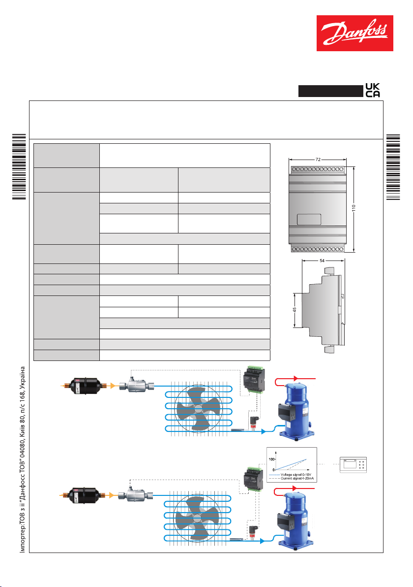
Electronic superheat controller - Modbus version
Type EKD 316C (Colibri®)
Introduction
EKD 316 is a superheat controller that can be used where there are requirements for accurate control of superheat.
Typically it will operate in Commercial air conditioning, heat pumps, commercial refrigeration, food retail and
084R8 047
industrial application. Compatible valve - Danfoss ETS / ETS C, K VS / KVS C and CCM / CCMT valves.
English
084R8 047
Supply voltage
Power consumption
24 V AC / DC ±15%, 50/60 Hz, 22 VA / 15 Watt
(the supply voltage is not galvanically
separated from the input and output signals)
Controller
ETS C / KVS C
ETS, KVS, CCM, CCMT
5 VA
7.2 VA
1.3 VA
Current signal * 4 - 20 mA or 0 - 20 mA
Input signal
*)Ri: mA: 400 Ohm
V: 50 kOhm
Voltage signal * 0 - 10 V or 1 - 5 V
Pressure transmitter
e.g. AKS 32R
0.5 - 4.5V DC ratiometric type
(10% - 90% of supply voltage)
Digital input from external contact function
Sensor input 2 pcs. Pt 1000 ohm
DI : < 800 Ohm = ON
DI : > 30 kOhm = OFF
Alarm relay 1 pcs. SPDT Max 24V, 1A resistive - Class II
Step motor output Pulsating 30 - 300 mA
Data communication RS 485 Modbus data communication
Operations 0 – 55 °C / 32 – 131 °F
Environments
Transportation -40 – 70 °C / -40 – 158 °F
Humidity 20 - 80 % Rh, none condensing
No shock influence/vibrations
Enclosure IP 20
Compatible valves Bipolar stepper motor valves
Standalone controller
ETS Colibri®
Danfoss
84B3177.10
Danfoss
Danfoss
Valve driver
© Danfoss | Climate Solutions | 2021.03
ETS Colibri®
OD
Danfoss
I/V
ss
nf
Danfoss
D
84B2707.10
1
11
4R64-3011.10
I/V
AN220086430005en-000502 | 1
Info for UK customers only:Danfoss Ltd. Oxford Road, UB9 4LH Denham, UK
Page 2
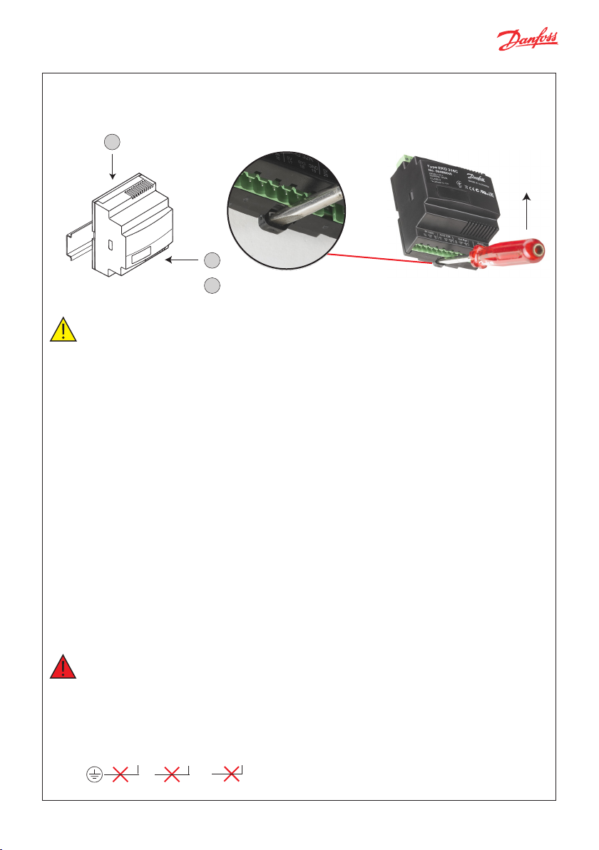
DIN rail mounting / dismounting
The unit can be mounted onto a 35 mm DIN rail (in accordance with EN 5022) simply by snapping it into place
and securing it with a stopper to prevent sliding. It is dismounted by gently pulling the stirrup located in the
base of the housing.
1
Danfoss
84B2714.11
2
“Click”
General warnings
• Every use that is not described in this manual is considered incorrect and is not authorised by the
manufacturer.
• Verify that the installation and operating conditions of the device respect the ones specified in the manual,
specially concerning the supply voltage and environmental conditions.
• This device contains live electrical components therefore all the service and maintenance operations
must be performed by qualified personnel.
• The device cannot be used as a safet y device.
• Liabilit y for injury or damage caused by the incorrect use of the device lies solely with the user.
Installation warnings
- The installation must be executed according the local standards and legislation of the country.
- Always operate on the electrical connections with the device disconnected from the main power supply.
- Before carrying out any maintenance operations on the device, disconnect all the electrical connections.
- For safet y reasons the appliance must be fitted inside an electrical panel with no live parts accessible.
- Don’t expose the device to continuous water sprays or to relative humidity greater than 80%.
- Avoid exposure to corrosive or pollutant gases, natural elements, environments where explosives or mixes of
flammable gases are present, dust, strong vibrations or chock, large and rapid fluctuations in ambient temperature
that in combination with high humidity can condensate, strong magnetic and/or radio interference
(e.g. transmitting antennae).
- When connecting loads beware of the maximum current for each relay and connector.
- Use cable ends suitable for the corresponding connectors. After tightening the screws of connectors, slightly tug
the cables to check their tightness.
- Use appropriate data communication cables. Refer to the Fieldbus Installation Guide for the kind of cable to be
used and setup recommendations.
- Reduce the path of the probe and digital inputs cables as much as possible, and avoid spiral paths enclosing power
devices. Separate from inductive loads and power cables to avoid possible electromagnetic noises.
- Avoid touching or nearly touching the electronic components fitted on the board to avoid electrostatic discharges.
Warnings
• Use a class II category transformer for 24 V AC power supply.
• Do not ground the 24 V AC wires.
• By connecting any EKD 316C inputs to mains voltage will permanently damage the controller.
• Do not apply voltage to the controller before the wiring is completed.
3
Dismounting
Pull down the stirrup to dismount unit from din rail
Connection of the terminals to earth will destroy the controller.
1,2 3,4 21,22
© Danfoss | Climate Solutions | 2021.03
AN220086430005en-000502 | 2
Page 3
Po
24
EKA 164A
ETS C valve
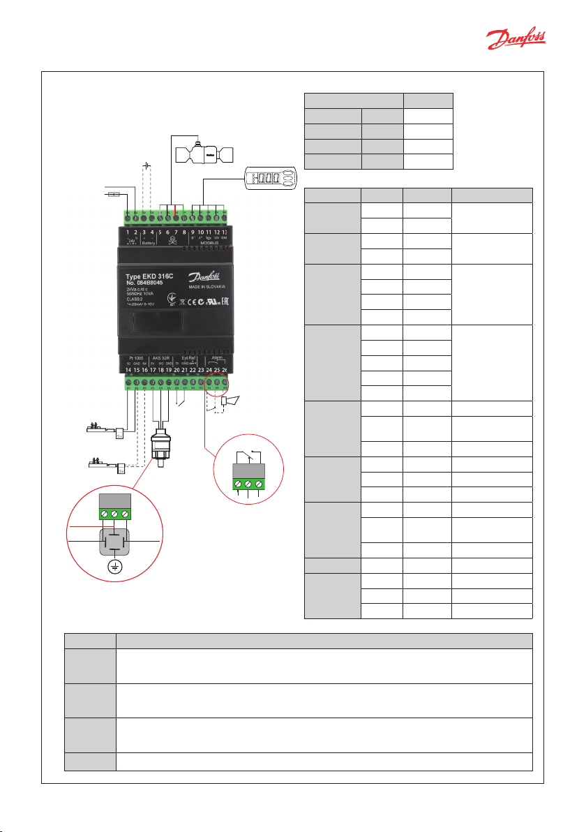
Connection overview
Connections
ETS Colibri® EKD 316C
White A1 5
Black A2 6
Red B1 7
Green B2 8
Connection overview table
Function Position Pin name Description
Power
supply
Batter y
backup
1 24V L /+
2 24V N/ -
3 Bat+
4 BAT-
wer supply
V AC / DC
Fuse 2 A
Battery
or similar
back-up
–
+
1
Modbus
5 A1
Stepper
motor
driver
6 A2
7 B1
8 B2
9 RS485 B -
10 RS485 A+
11 Shield
12 12 V
13 GND
14 S2 Pt 1000
15 GND
16 S4 Pt 1000 sensor
17 5 V Supply +
18 sig Output +
19 GND Common -
20 DI Switch
21 GND (-)
22 Sig (+) Analog signal
Temperature
sensor S2
Temperature
sensor S4
+ output
+ supply
Danfoss
84B3186.10
17
18
3
12
14 15
19
- common
DI
switch
Pressure
transmitter P0
AKS 32R
Alarm
relay
Data
communication
Temperature sensor
NC
Com
NO
Pressure
transmitter
External
reference
Not in use 23 – –
24 Com Common
Alarm
25 NC Normal closed
26 NO Normal open
Important notes
Terminals
3 - 4 Batter y backup (the voltage will close the ETS valve if the controller looses its supply voltage).
9 - 13 Operation via modbus communication either EKA 164A or system unit + software.
20 - 21 Switch function for start / stop of regulation.
The battery voltage must not be connected from terminals 1 and 2. Power of the battery lower
than 16.5 V will trigger the low batter y alarm.
It is important that the installation of the data communication cable is done correctly.
For detail refer to our EKD 316 manual.
Note: If a switch is not connected, terminals 20 and 21 must be short circuited. Do not connect
external power supply to these terminals, else it will damage the controller.
24 - 26 Alarm relay: There is connection between 24 and 26 in alarm situations.
Power supply
24 V DC
Battery backup
Stepper motor
RS485 Modbus/
external display
EK A 164A
Common ground
for S2 / S4
Common ground
for 20 /22
© Danfoss | Climate Solutions | 2021.03
AN220086430005en-000502 | 3
Page 4

Application dependent /optional Connections
Po
24
ETS C valve
e
D
E
64
0
+
ETS C valve
Po
24
C controller
ETS C valve
Po
24
P
t
s
u
s
A. Connection for standalone controller.
DI
I
switch
or similar
Modbus
Alarm relay
EKA 164A
KA 1
wer supply
V AC / DC
–
+
Fuse 2 A
Temperature
mperatur
sensor S2
Temperature
sensor S4
Danfoss
Danfoss
84B3183.10
84B3183.1
Battery
back-up
Pressure
transmitter P0
B. Connection for Valve Driver
using analog signal.
Application dependent connections
A. Superheat control
Terminals Necessary connections
14 - 15
15 - 16
Pt 1000 sensor at eavaporator outlet
(S2) for measuring superheat.
Pt 1000 sensor for measuring air
temperature (S4).
Pressure transmitter t ype AKS 32R.
17 - 19
Note:
The signal cannot be shared with
other controllers.
B. Control of the valve ope ning degree with analog
signal
21 - 22
Current signal or voltage signal from
other regulation (Ex t. Ref.)
C. Control of the valve with Mo dbus signal
9 - 10
Operation via RS 485
data communication
C. Connection for valve driver using
Modbus signal.
wer supply
V AC / DC
–
+
Fuse 2 A
PLC controller
© Danfoss | Climate Solutions | 2021.03
Danfoss
84B3184.10
Battery
back-up
–
+
Analog signal
or similar
Modbus
Alarm relay
EKA 164A
wer supply
V AC / DC
–
+
e 2A
Fuse 2 A
anfos
Danfoss
Battery
back-up
or similar
Modbus
4B3185.10
84B3185.10
Alarm relay
DI
switch
AN220086430005en-000502 | 4
LC con
PL
Page 5

84N401.10
evaporator
Sensor mounting: Temperature sensor
1 2 3
Danfoss
60G496.10
OD
OD
1
/2 - 5/8 in.
12 - 16 mm
3
/4 - 7/8 in.
18 - 22 mm
Conductive
paste
Evaporator outlet
Danfoss
84N366.11
1 - 1
OD
25 - 35 mm
3
1
OD
35 mm and higher
3
/8 in.
/8 in. and higher
Important Note
• Mount sensor on a clean
surface without any paints.
Danfoss
84N403.10
• Remember to put on heat
conducting paste and
insulate the sensor.
• Sensor mounting max. 5 cm
from the outlet of the
evaporatorto get the precise
measurements.
Evaporator
Close to the
Pressure transmitter
Installation of the pressure transmitter is less critical, but mounting of pressure transmitter should be closer to
the temperature sensor, right after the evaporator and with its head in upright position"
Power supply
• Grounding of secondary (output) of transformer is not recommended.
• Do not reverse the polarity of the power connection cables and avoid ground loops (i.e. avoid connecting one
field device to several controllers as this may result in short circuits and can damage your device.
• Use individual transformers for EKD 316C controller to avoid possible interference or grounding problems in
the power supply.
EKD 316C
Danfoss
EKD 316C
Danfoss
84N402.10
EKD 316C
EKD 316C
Relay Outputs
EKD 316C has 1 relay outputs:
• SPDT relay, connected to terminals 24 - 26 can be used either to connect solenoid valve or to connect alarm.
• Relay is designed for switching max. 24 V, 1A resistive - Class II.
© Danfoss | Climate Solutions | 2021.03
AN220086430005en-000502 | 5
Page 6

Cable and wiring
Danf
84N404.10
• The cable distance between the controller and the valve depends on many factors like shielded/unshielded cable,
the wire size used in the cable, the output power for the controller and EMC. In g eneral, for the cab le distance upto
10 m, it is recomm ended to use cable wi th wire size 22AWG or lower. For ca ble distance up to 30 m, wi re diameter
of 20 AWG or lower is recommended.
• In case o f electrical no ises in the system, us e cable filter AK 211.
• Keep controller and sensor wiring well separated from mains wiring. Minimum recommended distance 30mm.
• Connecting sensors by wires more than 6 m long may decrease the accuracy of measured values.
• Sensors and secondary (output) of transformer may not be grounded simultaneously.
Warning
Separate the sensor and digital input cables as much as possible (at least 3 cm) from the power cables to
the loads to avoid possible electromagnetic disturbance. Never lay power cables and probe cables in the
same conduits (including those in the electrical panels).
Connecting external display EKA 164A
To setup the EKD 316C an EKA 164A display is needed. The display can be used not only for setting up the
necessar y parameter but also to use as an external display during operating to show the impor tant
parameters i.e. opening degree of the valve, superheat etc.
EKA 164A EKD 316 C
EK A 164A
L = max. 30 m
R
R = 120 Ohm, min. 0.25 Watt
R
A+B-
9
10 121113
Danfoss
12 V
EKD 316C
Important Note:
• Max. distance bet ween controller and display is 30 m.
• The supply voltage to the display must be maintained at 12 V ± 15%.
• Terminal resistor of 120 Ohm is recomanded at both sides of the wire for
• length longer than 1 m to prevent elec trical noice.
84B3192.11
Connecting Modbus
• For the modbus cable, it is best to use 24 AWG shielded twisted-pair cable with a shunt capacitance of
16 pF/ft and 100Ω impedance.
• The controller provides an insulated RS485 communication interface which is connected to terminals 9 to 11
(see connection overview).
• The max. permissible number of devices simultaneously connec ted to RS485 output is 32. The RS485 cable is
of impedance 120 Ohm with maximum length of 1000 m.
• Terminal resistors 120 Ohm for terminal devices are recommended for length > 1 m.
In EKD 316C communication frequency (baudrate) can be one of the following:
9600 baud, 19200 baud and 384 00 baud.
• The only available fixed comm unication setti ngs in EKD 316C are 8 data bit, EVEN parity and 1 stop bit.
The def ault unit address is 240 which, can be changed using param eter “03 unit address ”.
Detail explanation on Modbus installation and sof tware parameter setting can be found on
Installation guide RC8AC602 and manual DKRCC.PS.RI0.F1.02.
© Danfoss | Climate Solutions | 2021.03
Modbus
A+
BNot in use
oss
Gnd
AN220086430005en-000502 | 6
Page 7

Stepper Motor Output
• All Valves are driven in a bipolar mode with a 24V supply that is chopped to control the current (Current driver).
• The stepper motor is connected to terminals 5 to 8 (see terminal assignment) with M12 motor cable.
• To configure stepper motor valves other than Danfoss stepper motor valve, it is necessary to set the right
valve parameters as described on section Valve configuration. The default valve setting in EKD 316C is
16 (i.e. ‘non’)
• It is neccesary to define correct valve in ‘Valve type’ i,e parameter n03. The overview of the valve types has
been defined in section “valve overview”.
Valve overview
n03 EKA 164A Danfoss valve type n37 n38
0 ETS 12.5, ETS 25, KVS 15 262 300
1 ETS 50, CCM 10, CCM 20, CCM30 262 300
2 ETS 100, CCM 40 353 300
3 ETS 250, KVS 42 381 300
4 ETS 400 381 300
5 User defined - -
6 UKV, SKV, VKV, PKV 24 16
7 ETS 6 24 16
8 CCMT 2, CCMT 4, CCMT 8 110 220
9 CTM16 80 200
10
11
12
13
14
15
16
17
CCMT 24
CCMT 30
CCMT 42
CTR
CCMT 0
CCMT 1
No valve se lected
ETS 12C, ETS 24C , ETS 25C, ETS 50C , ETS 100C, KVS 2C , KVS 3C, KVS 5C
140 200
230 200
220 200
660 75
24 16
24 16
10 160
60 160
© Danfoss | Climate Solutions | 2021.03
AN220086430005en-000502 | 7
Page 8

84B3193.10
For detail parameter list and explanation, please check the EKD 316C Manual.
Application specific setup
A. Supe rheat control
Use as cont roller (SH).
B. Valve drive r
Using analog signal.
Parameter Name PNU Value Value
o10 Ai type 2027 No signal 0 - 20 mA / 4 - 20 mA / 0 - 10 V / 1 - 5 V
o18 Manual control 2075 No override No override
o30 Refrigerant 2551 See EKD instruc tion for
refrigerant setting.
See EKD instruction for
refrigerant setting.
o61 App. mode 2077 2 = Superheat 1= Valve driver using analog signal
o20 Min. trans. press. 2034 Min. value on transmitter -
021 Max. trans. press 2033 Max. value on transmitter -
r12 Main switch 117 On
On
Valve configuration
Parameter Name PNU Description
n03 Valve type 3002 Define the proper valve type, check Valve over view for detail.
n37 Max. steps x 10 3032 Total number of full steps. on using EKA display, 800 step is
display as 80.
n38 Max. step / second (PPS) 3033 Define the require/recommended steps per sec.
n39 Start backlash (% of FS) 3034 (extra closing steps at 0 % opening (in % of n37))
n40 Backlash (steps) 3035 Compensation for spindle play.
n56 Motor current (mA) 30 51 Define the require current in mA RMS.
Note: Please refer to Danfoss EKD 316 manual for details.
Parameter setup
AA.. Setting controller in Superheat control mode.
Make sure that r12 = 0 (OFF) and change the settings
The setting will depends on the system requirement.
Selec t Refrigerant
o30 = 1-42 (default non selected)
Select val ve type
n03 = 0 - 9 (default is “non” i.e non valve selec ted).
On using EKA 164A display, check the valve
overview chart.
Define pressure sensor range in gauge bar
o20 = Min. Transducer pressure
o21 = Max. Transducer pressure
Set the application mode
BB.. Setting controller in valve driver m ode
using analog signal
Make sure that r12 = 0 (OFF) and change the
settings so they fit to their application:
Select Appication mode
o61 = 1 (remote/AI control)
Selec t Analog signal type
o10 = 2 (4-20mA)
(for other analog signal check the parameter list)
Select valve t ype
n03 = 17 (valve type, E TS C = 17)
for other valve types refer to valve overview table.
To s tar t the controlle r in Valve driver mode
Set r12 = ON
For MSS control n21 = 1 (de fault)
For Load define control n21 = 2
Define min/max superheat
n10 = min. superheat reference
n09 = max. superheat reference
For fixed superheat define n09 = n10
Define MOP (optional)
n11 = maximum operating pressure
(default is 20 bar, max. 200 = MOP off)
Set force opening of the valve ( opti onal)
Start OD% (n17 )
StartUp time (n15 )
To s tart the supeheat control
Set r12= ON
© Danfoss | Climate Solutions | 2021.03
Danfoss
AN220086430005en-000502 | 8
Page 9

EKD 316C – Parameter identification (Modbus)
Lock - the value can only be changed when the main switch is off
PNU - equivalent to to the modbus register no. (modbus adress + 1).
Actual value
Values are read/written as 16 bit integer values without decimals. This is the default value as read via modbus.
Scale
This shows the scaling factor of the value. *1 means that there is no scaling. *10 means that the read value
is 10 times larger than the actual value.
Parameter PNU R/W Lock Min. Max. Default
Actual
value
Scale
Regulation
Control
r12 Main switch (Off = 0 /
On = 1)
o10 AI type (0: no signal
1: 0-20 mA, 2: 4-20 mA
3: 0-10 V, 4: 1-5 V)
o61 should be set to 1 in
order to use this feature
o18 Manual control 2075
o45 Manual OD%
o56 Reg. type
1= Normal
2 = With inner loop
o61 Appl.mode
1: Valve driver mode using
analogue signal
2: Superheat regulation
Valve n03 Valve type
Ref. valve overview
n32 ETS OD% Max
n37 Max. steps [Stp]
n38 Max. Stp/Sec (Hz)
n39 Start backlash [%]
n40 Backlash [Stp]
n56 Motor current (mA RMS)
h22 Holding current [%]
Refrigerant
Refrigerant
o30
(Ref. appendix 1)
---
Rfg.Fac.A1 2548 R/W - 8000 - 10428 10428 *1
---
Rfg.Fac.A2 2549 R/W - -4000 - -2255 -2255 *1
---
Rfg.Fac.A3 2550 R/W - 1000 3000 2557 2557 *1
117 R/W - 0 1 0 0 *1
2027 R/W - 0 4 0 0 *1
R/W - 0 3 0 0 *1
2064 R/W - 0 100 0 0 *1
2076 R/W x 1 2 1 1 *1
2077 R/W x 1 2 2 2 *1
3002 R/W x 0 17 16 1 *1
3023 R/W - 0 100 100 100 *1
3032 R/W x 10 999 60 60 *1
3033 R/W x 5 300 160 160 *1
3034 R/W x 0 100 10 3 *1
3035 R/W x 0 100 0 0 *1
3051 R/W x 0 600 0 0 *1
2198 R/W x 0 100 0 0 *1
2551 R/W x 0 42 0 0 *1
Sensors r05
Temp.unit 105 R/W - 0 1 0 0 *1
r09
Adjust S2 [K] 113 R/W - -1 10 0 0 x10
r10
Adjust S4 [K] 114 R/W - -1 10 0 0 x10
Min. Trans. Pres.
o20
(bar relative)
Max. Trans. Pres.
o21
(bar relative)
o99
Enable high pressure alarm 219 9
© Danfoss | Climate Solutions | 2021.03
2034 R/W - -1 0 -1 -10 *10
2033 R/W - 1 200 12 120 *10
R/W - 0 1 0 0 *1
AN220086430005en-000502 | 9
Page 10

Parameter PNU R/W Lock Min. Max. Default
Actual
value
Scale
Injection
control
Service ---
Alarms A34
Read ou t u06
n04
Kp factor 3003 R/W - 0.5 20 2
n05
Tn seconds 3004 R/W - 30 600 120
n06
Td seconds 3005 R/W - 0 90 0
n09
Max SH 3015 R/W - 1 100 10
n10
Min SH 3021 R/W - 1 100 6
n11
MOP [bar] (max = off) 3013 R/W - 0 200 20
n15
Start time [sec] 3017 R/W - 1 90 0
n17
MinOdAtStart [%] 3012 R/W - 0 100 0
n18
Stability 3014 R/W - 0 10 5
n19
Kp min. 3024 R/W - 0 1 0.3
n20
Kp T0 3025 R/W - 0 10 0.4
n21
SH mode
1= MSS, 2 = Load app.
n22
SH close [K] 3027 R/W - 1 15 4
n44
TnT0 sec. 3039 R/W - 10 120 30
3026 R/W - 1 2 1
AL/Light rel 2509 R - 0 1 0
---
Reset alarm 2046 R/W - 0 1 0
---
EKC State 2007 R - 0 100 0
A34 Battery low 10035 R/W - 0 1 0
---
Standby 20000 R - 0 1 0
---
EKC Error 20001 R - 0 1 0
---
S2 Error 20002 R - 0 1 0
---
S3 Error 20003 R - 0 1 0
--- Peinp. error
---
AI inp.error 20005 R - 0 1 0
---
No Rfg. Sel. 20006 R - 0 1 0
20004 R - 0 1 0
Analog input [mA] 2504 R - 0 30 0
u10
DI1 status 2002 R - 0 1 0
u20
S2 temp. [°C] 2537 R - -200 200 0
u21
Superheat [K] 2536 R - 0 100 0
u22
Superheat Ref [K] 2535 R - 0 100 0
o03
Unit addr. 2008 R/W x 1 240 240
20 *10
120 *1
0 *1
100 *10
60 *10
200 *10
0 *1
0 *1
5 *1
3 *10
4 *10
1 *1
40 *10
30 *1
0 *1
0 *1
0 *1
0 *1
0 *1
0 *1
0 *1
0 *1
0 *1
0 *1
0 *1
0 *10
0 *1
0 *10
0 *10
0 *10
240 *1
Appendix 1
1 = R12 7 = R13b1 13 = User-defined 19 = R404A 25 = R290 31 = R422A R36 = Opteon XP10 41 = R449A
2 = R22 8 = R23 14 = R32 20 = R407C 26 = R600 32 = R413A 37 = R407F 42 = R452A
3 = R134a 9 = R500 15 = R227 21 = R407A 27 = R600a 33 = R422D 38 = R1234ze
4 = R502 10 = R503 16 = R401 22 = R407B 28 = R744 34 = 427A 39 = R1234yf
5 = R717 11 = R114 17 = R507 23 = R410A 29 = R1270 35 = R438A 40 = R44 8A
6 = R13 12 = R142b 18 = R402A 24 = R170 30 = R417A
Installation considerations
Accidental damage, poor installation, or site conditions can give rice to malfunctions of the control system, and
lead to a plant breakdown. Every possible safeguard is incorporated into our products to prevent this. However, an
incorrec t installation, for example, could still present problems. Elec tronic controls are no substitute for normal,
good engineering practice. Danfoss will not be responsible for any goods, or plant components, damaged as a result
of the above defects. It is the installers responsibility to check the installation thoroughly, and to fit the necessary
safety devices. Particular attention is drawn to the need for a “force closing” signal to controllers in the event of
compressor stoppage and to the signal requirement for suction line accumulators.
Your local Danfoss agent will be pleased to assist with further advice, etc.
© Danfoss | Climate Solutions | 2021.03
AN220086430005en-000502 | 10
 Loading...