

Page 1
Instructions
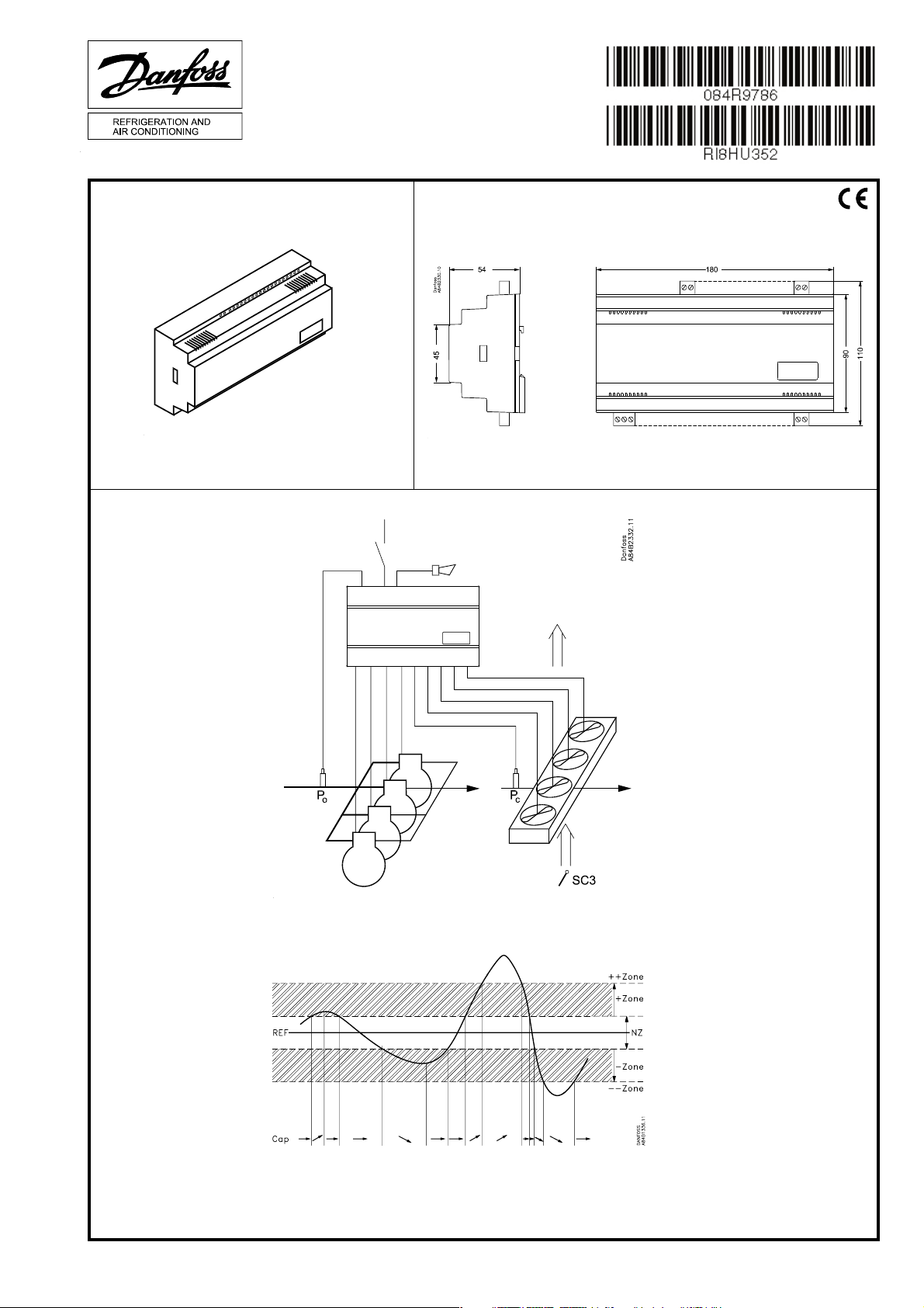
EKC 531D1
Identifi cation
Principle
Dimensions
084B8007
RI8HU352 12-2004
Page 2
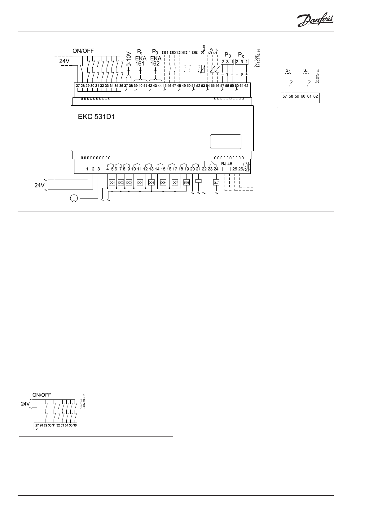
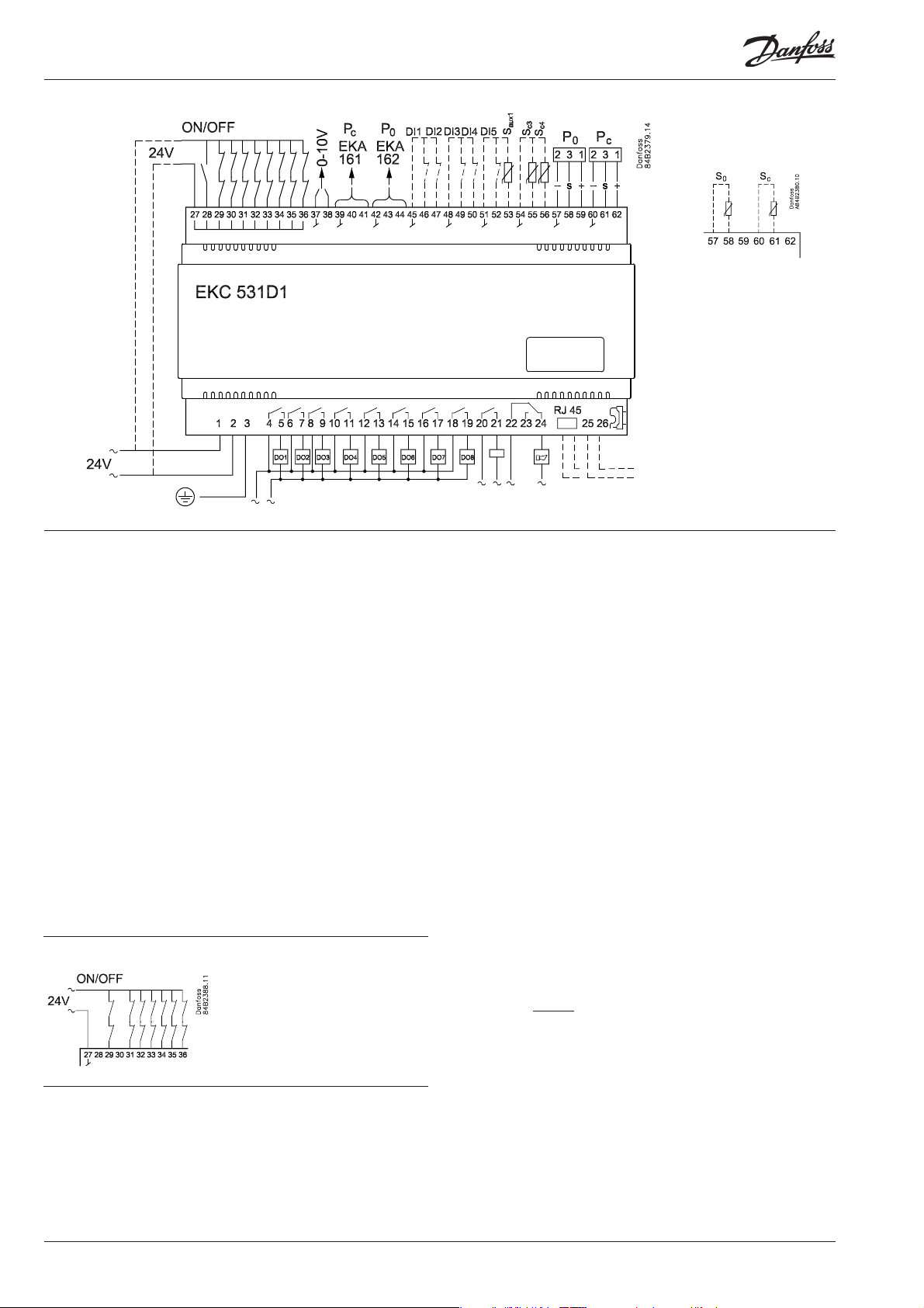
Connections
ENGLISH
Brine cooling
All inputs are low-voltage.
All relay outputs may be
high-voltage.
Data communication
Necessary connections
Terminals:
1-2 Supply voltage 24 V a.c.
4- 19 Relay outputs for either compressors, unloaders or
fan motors
22-24 Alarm relay *
There is connection between 22 and 24 in alarm situa tions
and when the controller is dead
27-28 24 V signal to start / stop of regulation
27-29 24 V signal from the safety circuit DO 1
27-30 24 V signal from the safety circuit DO 2
27-31 24 V signal from the safety circuit DO 3
27-32 24 V signal from the safety circuit DO 4
27-33 24 V signal from the safety circuit DO 5
27-34 24 V signal from the safety circuit DO 6
27-35 24 V signal from the safety circuit DO 7
27-36 24 V signal from the safety circuit DO 8
57-59 Suction pressure. Voltage signal from AKS 32R **
60-62 Condenser pressure. Voltage signal from AKS 32R **
54-55 Out temperature (Sc3). Sensor signal from AKS 11,
AKS 12 or EKS 111
Unloader
If an output is used for an unloader it is
not neccessary to wire the belonging
safety circuit.
*) Relays DO9 and DO10 may in special cases be reconfi gurated so that they can be
used as fan relays.
**)
• If the controller has to control only the comrpessor or the fans, respectively Pc and
Pc sensor can be dispensed
• In brine systems temperature measurement at terminals 57-58 and 60-61 may be
used instead of pressure measurement with AKS 32R. See also o06.
Application dependent connections
20-21 AKD start/stop *
The relay cutin when the frequency converter have to
start.
37-38 Voltage signal to external condenser control
39-41 Possibility of connecting an external display type
EKA 161 for display of Pc
42-44 Possibility of connecting an external display type
EKA 161 for display of P0, or EKA 162 for operation and
display of P0
45-46 Contact function for alarm signal
45-47 Contact function for alarm signal
48-49 Contact function for alarm signal
48-50 Contact function for displacement of the suction
pressure reference or for alarm signal.
51-52 Contact function for displacement of the condenser
pressure reference or for alarm signal.
51-53 Separate sensor Saux1. Sensor signal fra AKS 11,
AKS 12 or EKS 111
54-56 Air temperature at condenser outlet. Sensor signal
from AKS 11, AKS 12 or EKS 111
Data communication
25-26 Mount only, if a data communication module has
been mounted.
For ethernet communication the plug connection RJ45
must be used. (LON FTT10 can also be connected in this
way.
It is important that the installation of the data commu-
nication cable be done correctly. Cf. separate literature
No. RC8AC..
The termination bracket is placed to the right of
terminal 26.
2 Instructions RI8HU352 © Danfoss 12/2004 EKC 531D1
Page 3
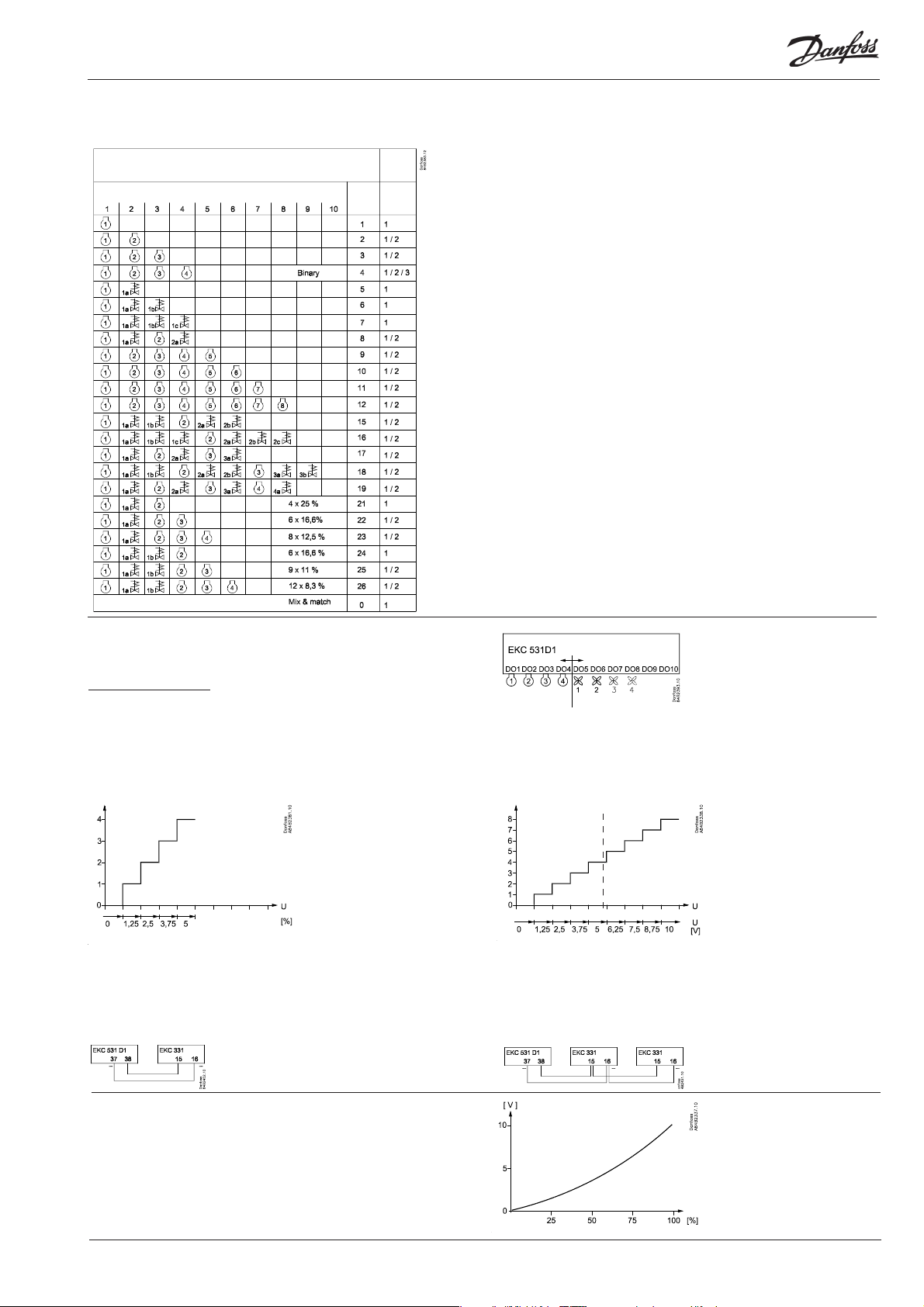
Compressor confi guration
Setting "C16" will defi ne the confi guration.
Setting "C08" will defi ne coupling mode.
Compressor connections
Relay no.
Set
"C16"
to
Coupling
mode
Set
"C08"
to
Capacity step
All capacity steps are presumed to
be identical. The only exception is
the settings C16 = 0, 4, and 21 to 26.
Coupling mode
Coupling mode 1 = sequential
operation.
Coupling mode 2 = cyclic operation.
Coupling mode 3 = cyclic and binary
operation where the compressor
capacities are, as follows:
1: 9%
2: 18%
3: 36%
4: 36%
There is cyclic coupling at 3 and 4,
and binary on 1, 2 and 3/4.
(for c16=4 only)
Couplings
When there is cyclic operation and
connections with unloaders there
will in some capacity cutins and
cutouts be overlappings where
the unloaders from either one
compressor or another may be
active.
In such cases the unloaders on the
compressor with the lowest number
of hours will be cut in, and the others
cut out.
The changeover will take place at
6-second intervals.
Equalised operation
When C16 = 21 to 26, compressor
1 + belonging unloader must have
the same capacity as each of the
subsequent compressors. The
unloading function will equalise the
cut-in capacity when the subsequent
compressors are cut in and out.
Compressor 1 will always be
operating.
User-defi ned combination.
Condenser couplings
When the compressor relays have been established the turn
comes to the fan relays.
The fi rst vacant relay (DO1-DO8) will become the fi rst fan relay.
It will be followed by the subsequent relays. If more relays are
required than the vacant DO relays, a relay module can be
connected to the analog output. The function is, as follows:
If there are up to four external fans on an EKC 331:
Output signal from EKC 531D1
In EKC 331 the voltage range must be set to 0-5 V (“o10” = 6).
In EKC 331 the number of steps must be set to 4 (“o19” = 4) (also when
fewer fans are connected).
Connection
If there are more than four external fans on two EKC 331 units:
1. 2.
Output signal from EKC 531D1
In the fi rst EKC 331, set 0-5 V (“o10” = 6).
In the second EKC 331, set 5-10 V (“o10” = 7).
In both EKC’s the number of steps must be set to 4 (“o19” = 4) (also when
fewer fans are connected to the second EKC).
Connection
If the entire condenser capacity is to be controlled by a
frequency converter, EKC 531D1 must send an analog
signal about the required capacity (“c29” = 9).
The signal varies from 0 to 10 V. Signal and capacity
have the following context.
EKC 531D1 Instructions RI8HU352 © Danfoss 12/2004 3
Page 4
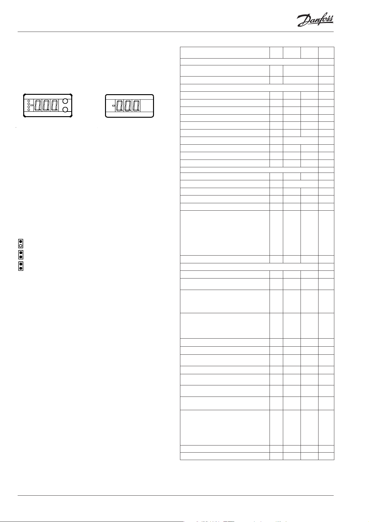
Operation
Display
The values will be shown with three digits, and with a setting you
can determine whether the pressures are to be shown in °C or i °F.
EKA 162
For operation and display of
evaporating pressure. The
light-emitting diodes on the
left-hand side fl ash when
there is an alarm.
The buttons
When you want to change a setting, the two buttons will give you
a higher or lower value depending on the button you are pushing. But before you change the value, you must have access to the
menu. You obtain this by pushing the upper button for a couple
of seconds - you will then enter the column with parameter codes.
Find the parameter code you want to change and push the two
buttons simultaneously. When you have changed the value, save
the new value by once more pushing the two buttons simultaneously.
Gives access to the menu
Gives access to changes
Saves a change
Operation
1. Push the upper button until a parameter is shown
2. Push one of the buttons and fi nd the parameter you want to
change
3. Push both buttons simultaneously until the parameter value is
shown
4. Push one of the buttons and select the new value
5. Push both buttons again to conclude the setting
During operation it is possible to show the condensing pressure
on the display EKA 162 by pushing the lower button short.
Quick- start
If you wish to start the system in a hurry so that refrigeration can
be commenced you can set the following eight parameters: r23
– r28 – c08 – c09 – c16 – c29 – o30, and fi nally r12.
When regulation has then started you can go through the
remaining parameters and adjust these.
Literature survey:
Manual EKC 531D1 RS8DD--Installation guide, Data communication link RC8AC---
Factory setting
If you need to return to the factory-set values, it can be done in this way:
- Cut out the supply voltage to the controller
- Keep both buttons depressed at the same time as you recon nect the supply voltage
EKA 161
For display of condensing
pressure.
(or cutout an alarm)
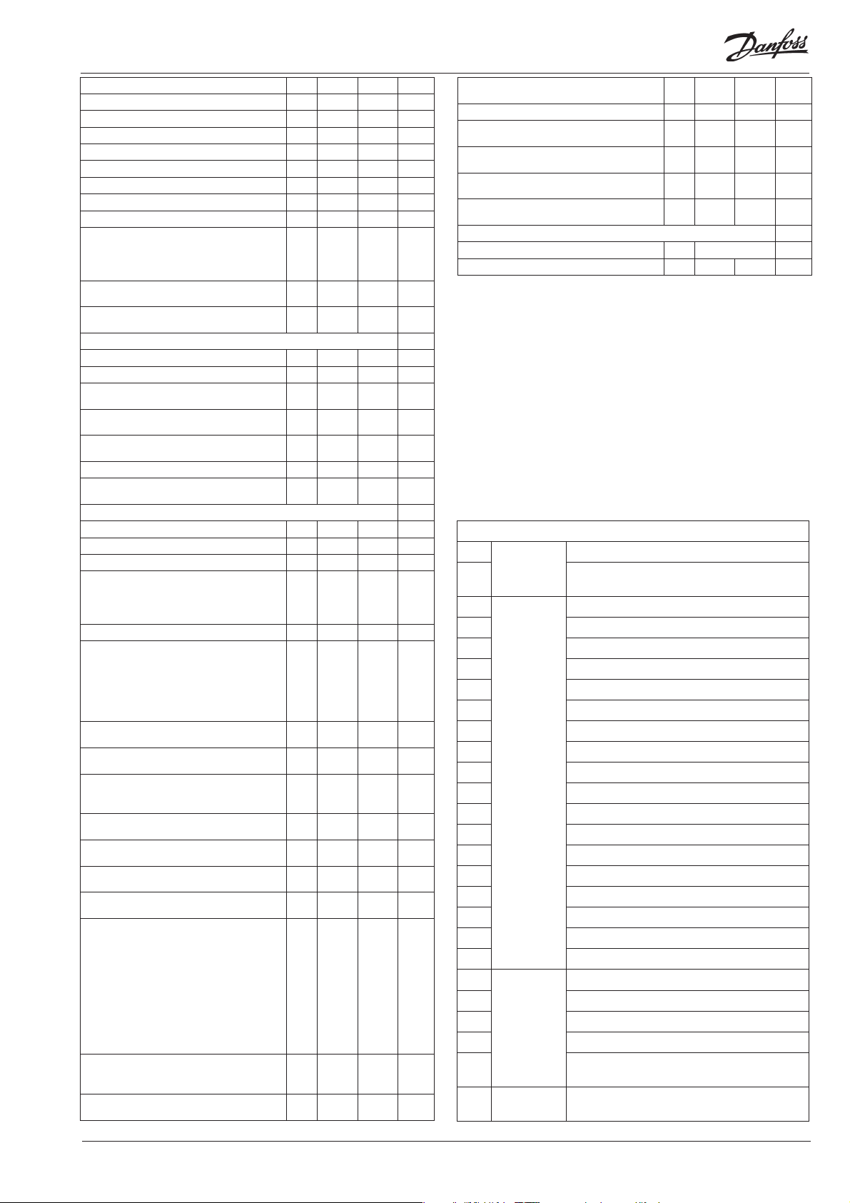
Menu survey EKC 531D1
Para-
Function
Normal display
Shows P0 in EKA 162 (display with buttons)
Shows Pc in EKA 161 - °C
P0 reference
Neutral zone r01 0.1 °C 20 °C 4.0
Correction of signal from P0 sensor r04 -10 °C 10 °C 0.0
Select unit (0=bar and °C, 1=Psig and °F) r05 0 1 0
Start/Stop of regulation r12 OFF ON 1
Reference off set for P0 r13 -20 °C 20 °C 0.0
Set regulation setpoint for P0 r23 -99 °C 30 °C 0.0
Shows total P0 reference r24 °C 0.0
Limitation: P0 reference max. value * r25 -99 °C 30 °C 30.0
Limitation: P0 reference min. value * r26 -99 °C 0 °C -99.9
Displacement of P0 (ON=active “r13”) r27 OFF ON 0
Pc reference
Set regulation setpoint for Pc r28 -25 °C 75 °C 35
Shows total Pc reference r29 °C 10
Limitation: Pc referencen max. value r30 -99 °C 99 °C 99.9
Limitation: Pc referencen min. value r31 -99 °C 99 °C -99.9
Correction of signal from Pc sensor r32 -10 °C 10 °C 0.0
Pc reference variation.1 and 2 are PIregulation
1: Fixed reference. “r28” is used
2: Variable reference. Outdoor temperature (Sc3) included in the reference
3: As 1, but with P-regulation (Xp-band)
4: As 2, but with P-regulation (Xp-band)
Reference off set for Pc r34 -20 °C 20 °C 0.0
Capacity
Min. ON time for relays c01 0 min 30 min. 0
Min. time period between cutins of same
relay
Defi nition of regulation mode
1: Sequential (step mode / FILO)
2: Cyclic (step mode / FIFO)
3: Binary and cyclic
If a regulation mode with unloaders is
selected, the relay must be defi ned to:
0: Cut in when more capacity is required
1: Cut out when more capacity is required
Regulation parameter for + Zone c10 0.1 K 20 K 4.0
Regulation parameter for + Zone c11 0.1 min 60 min 4.0
Regulation parameter for ++ Zone c12
Regulation parameter for - Zone c13 0.1 K 20 K 4.0
Regulation parameter for - Zone c14
Regulation parameter for - - Zone c15
Defi nition of compressor connections.See
options on page 10.
The following “c17” to “c28” is only relevant
if “c16” has been selected to 0.
A code will then have to be set for the
relays that are to be ON at the diff erent
steps:
Step 1 (M&M operation)
Step 2 (M&M operation) c18 0 15 0
Step 3 (M&M operation) c19 0 15 0
* also applies to regulation with reference displacement
Min. Max. Factory
meter
-°C
r33 1 4 1
c07 0 min. 60 min 4
c08 1 3 1
c09 0 1 0
0.1
min.
0.1
min.
0.02
min.
c16 0 26 0
c17 0 15 0
SW: 1.22
setting
20 min 2.0
60 min 1.0
20 min 0.5
Continues...
4 Instructions RI8HU352 © Danfoss 12/2004 EKC 531D1
Page 5
Step 4 (M&M operation) c20 0 15 0
Step 5 (M&M operation) c21 0 15 0
Step 6 (M&M operation) c22 0 15 0
Step 7 (M&M operation) c23 0 15 0
Step 8 (M&M operation) c24 0 15 0
Step 9 (M&M operation) c25 0 15 0
Step 10 (M&M operation) c26 0 15 0
Step 11 (M&M operation) c27 0 15 0
Step 12 (M&M operation) c28 0 15 0
Defi nition of condenser:
1-8: Total number of fan relays
9: Only via analog output and start of
frequency converter
Proportinal band Xp for (P= 100/Xp) condenser regulation
I: Integration time Tn for condenser regulation
Alarm
Delay time for a "Saux1" alarm A03 0 min. 90 min 30
Low alarm and safety limit for P0 A11 -99°C 30°C -10
Delay time for a DI1 alarm A27 1 s
Delay time for a DI2 alarm A28 1 s
Delay time for a DI3 alarm A29 1 s
Upper alarm and safety limit for Pc A30 -10 °C 99 °C 60.0
Upper alarm limit for sensor "Saux1" A32
Miscellaneous
Controllers address o03* 1 60
On/off switch (service-pin message) o04* - Access code o05 off (-1) 100
Used sensor type for Sc3, Sc4 and "Saux1"
0=PT1000, 1=PTC1000
2-7=variations with temperature sensor
on P0 and Pc. See earlier in the manual.
Set supply voltage frequency o12 50 Hz 60 H 0
Manual control of outputs:
0: No override
1-10: 1 will cut in relay 1, 2 relay 2, etc.
11-18: Gives voltage signal on the analog
output. (11 gives 1.25 V, and so on in steps
of 1.25 V
P0 pressure transmitter’s working range
- min. value
P0 pressure transmitter’s working range
- max. value
Use of DI4-input
0=not used. 1=P0 displacement. 2=alarm
function. Alarm="A31"
Operating hours of relay 1 (value time
1000)
Operating hours of relay 2 (value time
1000)
Operating hours of relay 3 (value time
1000
Operating hours of relay 4 (value time
1000)
Setting of refrigerant
1=R12. 2=R22. 3=R134a. 4=R502.
5=R717. 6=R13. 7=R13b1. 8=R23.
9=R500. 10=R503. 11=R114. 12=R142b.
13=User defi ned. 14=R32. 15=R227.
16=R401A. 17=R507. 18=R402A.
19=R404A. 20=R407C. 21=R407A.
22=R407B. 23=R410A. 24=R170.
25=R290. 26=R600. 27=R600a. 28=R744.
29=R1270. 30=R417A
Use of DI5-input
0=not used. 1=Pc displacment. 2=alarm
function. Alarm="A32"
Pc pressure transmitter’s working range
- min. value
c29 0/OFF 9 0
n04 0.2 K 40 K 10
n05 30 s 600 s 150
600 s
600
/off
600 s
600
/off
600 s
600
/off
0 °C
140°C 0.0
/off
o06 0 7 0
o18 0 18 0
o20 -1 bar 0 bar -1.0
o21 1 bar 40 bar 12.0
o22 0 2 0
o23 0.0 h 99.9 h 0.0
o24 0.0 h 99.9 h 0.0
o25 0.0 h 99.9 h 0.0
o26 0.0 h 99.9 h 0.0
o30 0 30 0
o37 0 2 0
o47 -1 bar 0 bar -1.0
Pc pressure transmitter’s working range
- max. value
Read temperature at sensor "Saux1" o49 0.0 °C °C 22.4
Operating hours of relay 5 (value time
1000)
Operating hours of relay 6 (value time
1000)
Operating hours of relay 7 (value time
1000)
Operating hours of relay 8 (value time
1000)
Service
Read temperature at sensor "Sc3" u44 °C 23.5
Read temperature at sensor "Sc4" u45 °C 8.1
*) This setting will only be possible if a data communication moduel has
been installed in the controller.
The controller can give the following messages
E1 Error
message
E2 Regulation is outside the range, or the control
A2 Alarm
message
A11 Refrigerant not selected
A17 High Pc
A19 DO 1 alarm. Terminal 29 is open
A20 DO 2 alarm. Terminal 30 is open
A21 DO 3 alarm. Terminal 31 is open
A22 DO 4 alarm. Terminal 32 is open
A23 DO 5 alarm. Terminal 33 is open
A24 DO 6 alarm. Terminal 34 is open
A25 DO 7 alarm. Terminal 35 is open
A26 DO 8 alarm. Terminal 36 is open
A27 Room temperature alarm (housing temp.)
A28 DI 1 alarm. Terminal 46 interrupted
A29 DI 2 alarm. Terminal 47 interrupted
A30 DI 3 alarm. Terminal 49 interrupted
A31 DI 4 alarm. Terminal 50 interrupted
A32 DI 5 alarm. Terminal 52 interrupted
A45 Regulation stopped
S2 Status
message
S5 Wait for “c07”
S8 Wait for “c11” or “c12”
S9 Wait for “c14” or “c15”
S10 Refrigeration stopped by the internal or external
PS Info Access code is required before you have access to
Fault in controller
signal is defective
Low P0
Wait for “c01”
start/stop function
the settings
o48 1 bar 60 bar 34.0
o50 0.0 h 99.9 h 0.0
o51 0.0 h 99.9 h 0.0
o52 0.0 h 99.9 h 0.0
o53 0.0 h 99.9 h 0.0
EKC 531D1 Instructions RI8HU352 © Danfoss 12/2004 5
Page 6
Tilslutninger
DANSK
Brinekøling
Alle indgange er lavvolt.
Alle relæudgange kan
være højvolt.
Datakommunikation
Nødvendige tilslutninger
Klemme:
1-2 Forsyningsspænding 24 V a.c.
4- 19 Relæudgange til enten kompressorer, afl astninger eller
ventilatormotorer
22-24 Alarmrelæet *
Der er forbindelse imellem 22 og 24 i alarmsituationer, og
når regulatoren er spændingsløs.
27-28 24 V signal til start / stop af reguleringen
27-29 24 V signal fra sikkerhedskredsen DO 1
27-30 24 V signal fra sikkerhedskredsen DO 2
27-31 24 V signal fra sikkerhedskredsen DO 3
27-32 24 V signal fra sikkerhedskredsen DO 4
27-33 24 V signal fra sikkerhedskredsen DO 5
27-34 24 V signal fra sikkerhedskredsen DO 6
27-35 24 V signal fra sikkerhedskredsen DO 7
27-36 24 V signal fra sikkerhedskredsen DO 8
57-59 Sugetryk. Spændingssignal fra AKS 32R **
60-62 Kondensatortryk. Spændingssignal fra AKS 32R **
54-55 Udetemperatur (Sc3). Følersignal fra AKS 11, AKS 12 eller
EKS 111
Afl astning
Hvis en udgang anvendes til en
afl astning, er det ikke nødvendigt, at
fortråde den tilhørende sikkerhedskreds.
Applicationbestemte tilslutninger
20-21 AKD start/stop *
Relæet slutter når frekvensomformeren skal starte.
37-38 Spændingssignal til ekstern kondensatorstyring
39-41 Mulighed for at tilslutte et eksternt display type EKA 161
(Pc-visning)
42-44 Mulighed for at tilslutte et eksternt display type EKA 161
til P0-visning, eller EKA 162 til betjening og P0-visning
45-46 Kontaktfunktion til alarmsignal
45-47 Kontaktfunktion til alarmsignal
48-49 Kontaktfunktion til alarmsignal
48-50 Kontaktfunktion til forskydning af sugetryksreferencen
eller til alarmsignal.
51-52 Kontaktfunktion til forskydning af kondensatortryksrefer-
encen eller til alarmsignal.
51-53 Separat føler Saux1. Følersignal fra AKS 11, AKS 12 eller EKS
111
54-56 Lufttemperatur ved kondensatorens afgang. Følersignal fra
AKS 11, AKS 12 eller EKS 111
Datakommunikation
25-26 Monteres kun, hvis der også er monteret et datakommu-
nikationsmodul.
Hvis det er en ethernetkommunikation skal stiktilslutningen RJ45 anvendes. (LON FTT10 kan også tilsluttes på
denne måde.)
Det er vigtigt, at installationen af datakommunikationskablet udføres korrekt.
Se separat litteratur nr. RC8AC..
Termineringsbøjlen er placeret til højre for klemme 26.
*) Relæerne DO9 og DO10 kan i specialtilfælde omkonfi gureres, så de kan anvendes
til ventilatorrelæ. Se yderligere side 8.
**)
• Hvis regulatoren kun skal styre kompressorer eller kun skal styre ventilatorer, kan Pc
henholdsvis Pc føleren undværes.
• På brineanlæg kan der i stedet for trykmåling med AKS 32R anvendes temperatur-
måling på klemme 57-58 og 60-61. Se også o06.
6 Instructions RI8HU352 © Danfoss 12/2004 EKC 531D1
Page 7

Kompressorkonfi guration
Indstilling "C16" vil defi nere konfi gurationen.
Indstilling "C08" vil defi nere koblingsmåden.
Kompressor tilslutninger
Relæ nr
Indstil
"C16"
til
Koblingsmåde
Indstil
"C08"
til
Kapacitetstrin
Alle kapacitetstrin forudsættes at
være lige store. Eneste undtagelse
er indstillingerne C16 = 0, 4, og 21
til 26.
Koblingsmåde
Koblingsmåde 1 er sekventiel drift.
Koblingsmåde 2 er cyklisk drift.
Koblingsmåde 3 er cyklisk og binær
drift. Hvor kapaciteten på kompressorerne er følgende:
1: 9%
2: 18%
3: 36%
4: 36%
Her kobles der cyklisk på 3 og 4,
og binært på 1, 2 og 3/4.
(Kun for c16 = 4)
Omkoblinger
Ved cyklisk drift og tilslutninger med
afl astninger, vil der ved nogle kapacitetsindkoblinger være overlapninger, hvor afl astningerne fra enten
den ene eller den anden kompressor
kunne være aktiv.
I disse tilfælde vil afl astningerne
på kompressoren med det laveste
timetal blive koblet ind, og de andre
blive koblet ud. Omkoblingen vil ske
med et interval på 6 sekunder.
Udjævnet drift
Ved C16 = 21 til 26 skal kompressor
1 + den tilhørende afl astning have
samme kapacitet som hver af de
efterfølgende kompressorer.
Afl astningen vil udglatte den indkoblede kapacitet, når de efterfølgende kompressorer bliver ind- og
udkoblet.
Kompressor 1 vil altid være i drift.
Brugerdefi neret kombination.
Kondensatorkoblinger
Når kompressorrelæerne er lagt fast, kommer turen til ventilatorrelæerne.
Det første ledige relæ (DO1-DO8) bliver det første ventilatorrelæ.
Derefter kommer de efterfølgende. Er der fl ere end de ledige
DO-relæer på regulatoren, kan der tilsluttes et relæmodul på den
analoge udgang. Funktionen er følgende:
Hvis der er op til 4 eksterne ventilatorer på en EKC 331:
Udgangssignal fra EKC 531D1
I EKC 331 skal spændingsområdet indstilles til 0-5 V ("o10"=6).
I EKC 331 skal antal trin indstilles til 4 ("o19"=4) (også selv om der er tilsluttet færre ventilatorer).
Tilslutning
Hvis der er fl ere end 4 eksterne ventilatorer på 2 stk. EKC 331:
1. 2.
Udgangssignal fra EKC 531D1
I den første EKC 331 indstilles 0-5 V ("o10"=6).
I den anden EKC 331 indstilles 5-10 V ("o10"=7).
I begge EKC 331 skal antal trin indstilles til 4 ("o19"=4) (også selv om der
på den anden er tilsluttet færre ventilatorer).
Tilslutning
Hvis hele kondensatorkapaciteten skal styres af en
frekvensomformer, skal EKC 531D1 afgive et analogt
signal om den ønskede kapacitet ("c29"=9).
Signalet varierer fra 0 til 10 V. Signal og kapacitet har
følgende sammenhæng.
EKC 531D1 Instructions RI8HU352 © Danfoss 12/2004 7
Page 8

Betjening
Menuoversigt EKC 531D1
SW: 1.22
Display
Værdierne bliver vist med tre cifre, og med en indstilling kan du
bestemme, om trykket skal vises i °C eller i °F.
EKA 162
Til betjening og visning af
fordampningstrykket.
EKA 161
Til visning af kondenserings-
trykket.
Lysdioderne i venstre side
blinker ved alarm.
Knapperne
Når du vil ændre en indstilling, vil de to knapper give en højere eller en lavere værdi alt efter hvilken knap, du trykker på. Men før du
kan ændre værdien, skal du have adgang ind i menuen. Det får du
ved at trykke på den øverste knap i et par sekunder – så kommer
du ind i rækken med parameterkoder. Find den parameterkode
du vil ændre, og tryk så på begge knapper samtidig. Når du har
ændret værdien, gemmer du den nye værdi ved igen at trykke på
begge knapper samtidig.
Eller kort:
Giver adgang til menuen (eller udkoble en alarm)
Giver adgang til at ændre
Gemmer en ændring.
Betjening
1. Tryk på den øverste knap til der vises en parameter
2. Tryk på en af knapperne og fi nd hen til den parameter, du vil
indstille
3. Tryk på begge knapper samtidig indtil værdien for parameteren
vises
4. Tryk på en af knapperne og vælg den nye værdi
5. Tryk igen på begge knapper for at afslutte indstillingen.
Under drift kan du få vist kondenseringstrykket på EKA 162, ved at
trykke kortvarigt på den nederste knap.
Quick- start
Hvis du vil have anlægget igang i en fart, så nedkølingen kan
påbegyndes, kan du indstille følgede 8 parametre.
r23 - r28- c08 - c09 - c16 - c29 - o30 og til sidst r12.
Når reguleringen derefter er igang, kan du gå igennem de øvrige
parametre og justere dem på plads.
Litteratur oversigt:
Manual EKC 531D1 RS8DD--Installationsguide, Data kommuniktion link RC8AC---
Fabriksindstilling
Hvis du får behov for at vende tilbage til de fabriksindstillede værdier, kan det ske
således:
- Afbryd forsyningsspændingen til regulatoren
- Hold begge knapper inde samtidig med at du igen tilslutter forsyningsspændingen.
Para-
Funktion
Normalbillede
P0 vises i EKA 162 (den med betjeningsknapper)
Pc vises i EKA 161 - °C
P0 reference
Neutralzone r01 0.1 °C 20 °C 4.0
Korrektion af signalet fra P0-føleren r04 -10 °C 10 °C 0.0
Vælg enhed (0=bar og °C, 1=Psig og °F) r05 0 1 0
Start/Stop af kølingen r12 OFF ON 1
Referenceoff set for P0 r13 -20 °C 20 °C 0.0
Indstille reguleringens setpunkt for P0 r23 -99 °C 30 °C 0.0
Her vises den samlede P0-reference r24 °C 0.0
Begrænsning: P0-referencens max. værdi* r25 -99 °C 30 °C 30.0
Begrænsning: P0-referencens min. værdi* r26 -99 °C 0 °C -99.9
Forskydning af P0 (ON=aktiv "r13") r27 OFF ON 0
Pc reference
Indstille reguleringens setpunkt for Pc r28 -25 °C 75 °C 35
Her vises den samlede Pc-reference r29 °C 10
Begrænsning: Pc-referencens max. værdi r30 -99 °C 99 °C 99.9
Begrænsning: Pc-referencens min. værdi r31 -99 °C 99 °C -99.9
Korrektion af signalet fra Pc-føleren r32 -10 °C 10 °C 0.0
Pc-referencens variation.
1 og 2 er PI regulering
1: Fast reference. "r28" anvendes
2: Variabel reference. Udetemperaturen
(Sc3) indgår i referencen
3: Som 1, men med P-regulering (Xpbånd)
4: Som 2, men med P-regulering (Xpbånd)
Referenceoff set for Pc r34 -20 °C 20 °C 0.0
Kapacitet
Min. On-tid for relæer c01 0 min 30 min. 0
Min. periodetid imellem indkobling af det
samme relæ
Defi nition af reguleringsmåden
1: Sekventiel (step mode / FILO)
2: Cyklisk (step mode / FIFO)
3: Binær og cyklisk
Hvis der vælges en reguleringsmåde med
afl astninger skal relæet defi neres til at:
0: Slutte ved krav om mere kapacitet
1: Bryde ved krav om mere kapacitet
Reguleringsparameter for + Zone c10 0.1 K 20 K 4.0
Reguleringsparameter for + Zone c11 0.1 min 60 min 4.0
Reguleringsparameter for ++ Zone c12
Reguleringsparameter for - Zone c13 0.1 K 20 K 4.0
Reguleringsparameter for - Zone c14
Reguleringsparameter for - - Zone c15
Defi nition af kompressortilslutninger.
Se mulighederne side 10.
Følgende "c17" til "c28" er kun aktuel, hvis
"c16" er valgt til 0.
Der skal så indstilles en kode for hvilke
relæer, der er on ved de forskellige step:
Step 1 (M&M drift)
Step 2 (M&M drift) c18 0 15 0
Step 3 (M&M drift) c19 0 15 0
* gælder også ved regulering med referenceforskydning
Min. Max.
meter
-°C
r33 1 4 1
c07 0 min. 60 min 4
c08 1 3 1
c09 0 1 0
0.1
min.
0.1
min.
0.02
min.
c16 0 26 0
c17 0 15 0
Fabriksindstilling
20 min 2.0
60 min 1.0
20 min 0.5
Fortsættes
8 Instructions RI8HU352 © Danfoss 12/2004 EKC 531D1
Page 9

Step 4 (M&M drift) c20 0 15 0
Step 5 (M&M drift) c21 0 15 0
Step 6 (M&M drift) c22 0 15 0
Step 7 (M&M drift) c23 0 15 0
Step 8 (M&M drift) c24 0 15 0
Step 9 (M&M drift) c25 0 15 0
Step 10 (M&M drift) c26 0 15 0
Step 11 (M&M drift) c27 0 15 0
Step 12 (M&M drift) c28 0 15 0
Defi nition af kondensator:
1-8: Total antal ventilatorrelæer
9: Kun via analog udgang og start af
frekvensomformer
Proportionalbånd Xp for (P = 100/Xp)
kondensatorreguleringen
I: Integrationstid Tn for kondensatorreguleringen
Alarm
Forsinkelsestid for en "Saux1" alarm A03 0 min. 90 min 30
Nedre alarm- og sikkerhedsgrænse for P0 A11 -99°C 30 °C -10
Forsinkelsestid for en DI1-alarm A27 1 s
Forsinkelsestid for en DI2-alarm A28 1 s
Forsinkelsestid for en DI3-alarm A29 1 s
Øvre alarm- og sikkerhedsgrænse for Pc A30 -10 °C 99 °C 60.0
Øvre alarmgrænse for føleren "Saux1" A32
Diverse
Regulatorens adresse o03* 1 60
On/off omskifter (service-pin meddelelse) o04* - Adgangskode o05 off (-1) 100
Anvendt følertype til Sc3, Sc4 og "Saux1"
0=PT1000, 1=PTC1000
2-7= variationer med temperaturføler på
P0 og Pc. Se tidligere i manualen.
Indstille forsyningsspændingens frekvens o12 50 Hz 60 H 0
Manuel styring af udgange:
0: Ingen overstyring
1-10: 1 vil trække relæ 1, 2 relæ 2, osv.
11-18: Giver spændingssignal på den
analoge udgang. (11 giver 1,25 V og ellers
videre i step på 1,25 V.)
P0-tryktransmitterens arbejdsområde
- min. værdi
P0-tryktransmitterens arbejdsområde
- max. værdi
DI4-indgangens anvendelse
0=benyttes ikke. 1=P0-forskydning.
2=alarmfunktion. Alarm="A31"
Driftstid af relæ 1 (værdi gange 1000) o23 0.0 h 99.9 h 0.0
Driftstid af relæ 2 (værdi gange 1000) o24 0.0 h 99.9 h 0.0
Driftstid af relæ 3 (værdi gange 1000) o25 0.0 h 99.9 h 0.0
Driftstid af relæ 4 (værdi gange 1000) o26 0.0 h 99.9 h 0.0
Kølemiddelindstilling
1=R12. 2=R22. 3=R134a. 4=R502.
5=R717. 6=R13. 7=R13b1. 8=R23.
9=R500. 10=R503. 11=R114. 12=R142b.
13=Brugerdefi neret. 14=R32. 15=R227.
16=R401A. 17=R507. 18=R402A.
19=R404A. 20=R407C. 21=R407A.
22=R407B. 23=R410A. 24=R170.
25=R290. 26=R600. 27=R600a. 28=R744.
29=R1270. 30=R417A
DI5-indgangens anvendelse
0=benyttes ikke. 1=Pc-forskydning.
2=alarmfunktion. Alarm="A32"
Pc-tryktransmitterens arbejdsområde
- min. værdi
Pc-tryktransmitterens arbejdsområde
- max. værdi
c29 0/OFF 9 0
n04 0.2 K 40 K 10
n05 30 s 600 s 150
600 s
600
/off
600 s
600
/off
600 s
600
/off
0 °C
140°C 0.0
/off
o06 0 7 0
o18 0 18 0
o20 -1 bar 0 bar -1.0
o21 1 bar 40 bar 12.0
o22 0 2 0
o30 0 30 0
o37 0 2 0
o47 -1 bar 0 bar -1.0
o48 1 bar 60 bar 34.0
Afl æse temperaturen ved føleren "Saux1" o49 0.0 °C °C 22.4
Driftstid af relæ 5 (værdi gange 1000) o50 0.0 h 99.9 h 0.0
Driftstid af relæ 6 (værdi gange 1000) o51 0.0 h 99.9 h 0.0
Driftstid af relæ 7 (værdi gange 1000) o52 0.0 h 99.9 h 0.0
Driftstid af relæ 8 (værdi gange 1000) o53 0.0 h 99.9 h 0.0
Service
Afl æse temperaturen ved føleren "Sc3" u44 °C 23.5
Afl æse temperaturen ved føleren "Sc4" u45 °C 8.1
*) Denne indstilling vil kun være mulig, hvis der er monteret et datakommunikationsmodul i regulatoren.
Regulatoren kan give følgende meddelelser:
E1 Fejl-
meddelelse
E2
A2 Alarm-
meddelelse
A11 Der er ikke valgt kølemiddel
A17 Høj Pc
A19 DO 1 alarm. Klemme 29 er åben
A20 DO 2 alarm. Klemme 30 er åben
A21 DO 3 alarm. Klemme 31 er åben
A22 DO 4 alarm. Klemme 32 er åben
A23 DO 5 alarm. Klemme 33 er åben
A24 DO 6 alarm. Klemme 34 er åben
A25 DO 7 alarm. Klemme 35 er åben
A26 DO 8 alarm. Klemme 36 er åben
A27 Rumtemperaturalarm (Saux1 temp.)
A28 DI 1 alarm. Klemme 46 er afbrudt
A29 DI 2 alarm. Klemme 47 er afbrudt
A30 DI 3 alarm. Klemme 49 er afbrudt
A31 DI 4 alarm. Klemme 50 er afbrudt
A32 DI 5 alarm. Klemme 52 er afbrudt
A45 Reguleringen er stoppet
S2 Status-
meddelelser
S5 Afventer "c07"
S8 Afventer "c11" eller "c12"
S9 Afventer "c14" eller "c15"
S10
PS Info
Fejl i regulatoren
Reguleringen er uden for området, eller styresignal er defekt
Lav P0
Afventer "c01"
Kølingen er stoppet med den interne eller eksterne start/stop
Adgangskoden er påkrævet inden du får adgang
til indstillinger.
EKC 531D1 Instructions RI8HU352 © Danfoss 12/2004 9
Page 10

Anschlüsse
DEUTSCH
Solekühlung
Alle Eingänge sind nur für
Niederspannung geeignet.
Alle Relaisausgänge sind
für Hochspannung ausgelegt.
Datenkommunikation
Benötigte Anschlüsse
Klemme:
1-2 Versorgungsspannung 24 V a.c.
4- 19 Relaisausgänge für entweder Verdichter, Entlastungen
oder Lüftermotoren
22-24 Alarmrelais *
Es besteht Verbindung zwischen 22 und 24 in Alarmsituationen, und wenn der Regler Spannungslos ist.
27-28 24 V Signal für Start / Stop der Regelung
27-29 24 V Signal vom Sicherheitskreis DO 1
27-30 24 V Signal vom Sicherheitskreis DO 2
27-31 24 V Signal vom Sicherheitskreis DO 3
27-32 24 V Signal vom Sicherheitskreis DO 4
27-33 24 V Signal vom Sicherheitskreis DO 5
27-34 24 V Signal vom Sicherheitskreis DO 6
27-35 24 V Signal vom Sicherheitskreis DO 7
27-36 24 V Signal vom Sicherheitskreis DO 8
57-59 Saugdruck. Spannungssignal vom AKS 32R **
60-62 Verfl üssigungsdruck. Spannungssignal vom AKS 32R **
54-55 Aussentemperatur (Sc3). Fühlersignal vom AKS 11, AKS 12
oder EKS 111
Entlastungen
Wird ein Ausgang für eine Entlastung
benutzt, ist Verdrahtung zu den zugehörigen Sicherheitskreis nicht notwendig.
*) Die Relais DO9 und DO10 lassen sich in speziellen Fällen umkonfi gurieren, um als
Lüfterrelais eingesetzt werden zu können. Nähere Angaben siehe Seite 8.
**)
• Wenn der Regler nur die Verdichter oder die Lüfter regeln soll, kann Pc beziehungs-
weise Pc Fühler entbehrt werden.
• Bei Soleanlagen kann anstatt der Druckmessung mittels AKS 32R eine Temperatur-
messung an den Klemmen 57-58 und 60-61 erfolgen. Siehe auch o06.
Anwendungsbestimte Anschlüsse
20-21 AKD Start/stop *
Das Relais schliesst wenn der Frequenzumrichter
starten soll.
37-38 Spannungssignal für eksterne Verfl üssigerregelung
39-41 Anschlussmöglichkeit für ein eksternes Display von Typ
EKA 161 (Pc-anzeige)
42-44 Anschlussmöglichkeit für ein eksternes Display von Typ
EKA 161 für P0-anzeige, oder EKA 162 zur Bedienung
und P0-Anzeige
45-46 Kontaktfunktion für Alarmsignal
45-47 Kontaktfunktion für Alarmsignal
48-49 Kontaktfunktion für Alarmsignal
48-50 Kontaktfunktion für verschiebung des Saugdruck Soll werts oder für Alarmsignal.
51-52 Kontaktfunktion für verschiebung des Verfl üssiger
druck Sollwerts oder für Alarmsignal.
51-53 Separate Fühler Saux1. Fühlersignal von AKS 11, AKS 12
oder EKS 111
54-56 Lufttemperatur am Verfl üssiger abgang. Fühlersignal
von AKS 11, AKS 12 oder EKS 111
Datenkommunikation
25-26 Nur bei montiertem Datenkommunikationsmodul
anzuschließen.
Erfolgt die Kommunikation über ein Ethernet, sind
Steckanschlüsse RJ45 anzuwenden. (LON FTT10 kann
ebenfalls auf diese Weise angeschlossen werden.)
Bitte beachten, dass die Installation des Datenkommu-
nikationskabels korrekt vorgenommen wird.
Siehe separate Literatur Nr. RC8AC..
Die Terminierungsbrücke ist rechts von Klemme 26
platziert.
10 Instructions RI8HU352 © Danfoss 12/2004 EKC 531D1
Page 11

Verdichterkonfi guration
Einstellung "C16" wird die Konfi guration defi nieren
Einstellung "C08" wird die Konfi guration defi nieren
Verdichteranschluss
Relais Nr.
Einstell
"C16"
Schaltungsart
Einstell.
"C08"
Leistungsstufen
Es wird vorausgesetzt, dass alle Leis-
tungsstufen gleich groß sind. Einzige
Ausnahme sind die Einstellungen
C16 = 0, 4 und 21 bis 26.
Schaltungsart
Schaltungsart 1 gilt für sequenziellen
Betrieb.
Schaltungsart 2 gilt für zyklischen
Betrieb.
Schaltungsart 3 gilt für zyklischen
und binären Betrieb. Bei folgenden
Verdichterleistungen:
1: 9%
2: 18%
3: 36%
4: 36%
Hier wird zyklisch auf 3 und 4 geschaltet, und binär auf 1, 2 und 3/4.
(Nur bei C16 = 4)
Umschaltungen
Bei zyklischem Betrieb und Anschlüssen mit Entlastungen
treten bei bestimmten Leistungszuschaltungen Überlappungen auf,
wobei die Entlastungen entweder
des einen oder anderen Verdichters
aktiv sein können.
In diesen Fällen werden die Entlastungen des Verdichters mit der
niedrigsten Betriebsstundenzahl
ein- und die anderen abgeschaltet.
Die Umschaltung erfolgt mit einem
Intervall von 6 Sekunden.
Ausgeglichener Betrieb
Bei C16 = 21 bis 26 muss Verdichter
1 + die zugehörige Entlastung die
gleiche Leistung haben, wie jeder
der nachfolgenden Verdichter.
Die Entlastung gleicht die zugeschaltete Leistung aus, wenn die
nachfolgenden Verdichter zu- und
abgeschaltet werden.
Verdichter 1 ist immer in Betrieb.
Benutzerdefi nierte Kombination.
Ver fl üssigerschaltungen
Nachdem die Verdichterrelais festgelegt wurden, sind die Lüfterrelais an der Reihe.
Das erste freie Relais (DO1-DO8) wird zum ersten Lüfterrelais.
Anschließend alle weiteren. Werden mehr als die freien DO-Relais
am Regler benötigt, kann am Analogausgang ein Relaismodul mit
folgender Funktion angeschlossen werden:
Wenn mehr als 4 externe Lüfter bei einem EKC 331 vorhanden sind:
Ausgangssignal vom EKC 531D1
In EKC 331 ist der Spannungsbereich auf 0-5 V (“o10”=6) einzustellen.
In EKC 331 ist die Stufenanzahl auf 4 (“o19”=4) einzustellen (auch, wenn
weniger Lüfter angeschlossen sein sollten).
Anschluss
Wenn mehr als 4 externe Lüfter an 2 EKC 331 angeschlossen sind:
1. 2.
Ausgangssignal vom EKC 531D1
Ist im ersten EKC 331 auf 0-5 V (“o10”=6) einzustellen.
Ist im zweiten EKC 331 auf 5-10 V (“o10”=7) einzustellen.
In beiden EKC 331 ist die Stufenanzahl auf 4 (“o19”=4) einzustellen (auch,
wenn weniger Lüfter angeschlossen sein sollten).
Anschluss
Soll die gesamte Verfl üssigerleistung mit einem Frequenzumrichter geregelt werden, muss EKC 531D1 ein
der gewünschten Leistung entsprechendes analoges
Signal (“c29”=9) abgeben.
Das Signal variiert von 0 bis 10 V. Signal und Leistung
hängen wie folgt zusammen.
EKC 531D1 Instructions RI8HU352 © Danfoss 12/2004 11
Page 12

Bedienung
Display
Die Wertdarstellung erfolgt dreistellig. Es besteht die Wahl
zwischen Anzeige in °C oder in °F.
EKA 162
Zur Bedienung und Anzeige
des Verdampfungsdrucks.
Leuchtdioden auf der linken
Seite blinken bei Alarm.
Tasten
Mit den beiden Tasten lassen sich die Einstellungen ändern. Je
nachdem, welche Taste Sie betätigen, ergibt sich ein höherer oder
niedrigerer Wert. Bevor Werte geändert werden können, muss
Zugang zum Menü hergestellt werden. Durch einige Sekunden
langes Betätigen der obersten Taste erhält man Zugang zu
einer Reihe von Parametercodes. Wählen Sie den zu ändernden
Parametercode aus, und betätigen Sie anschließend beide Tasten
gleichzeitig. Nach Änderung des Werts lässt sich der neue Wert
speichern, indem erneut beide Tasten gleichzeitig betätigt werden.
Kurz zusammengefasst:
Zugang zum Menü (oder schaltet einen Alarm aus)
Zugang zu Änderungen
Speichert eine Änderung
Bedienung
1. Die oberste Taste betätigen, bis ein Parameter zur Anzeige
gelangt.
2. Eine der Tasten betätigen, um zum gewünschten Parameter zu
gelangen.
3. Beide Tasten gleichzeitig betätigen, bis der Wert des Parameters
zur Anzeige kommt.
4. Eine der Tasten betätigen, und einen neuen Wert festlegen.
5. Erneut beide Tasten betätigen, um den Einstellvorgang
Während des Betriebs ist die Anzeige des Verfl üssigungsdruck auf
EKA 162 möglich, durch einen kurzem druck auf der untersten
Taste zu bekommen.
Schnellstart
Soll die Anlage schnell angefahren werden, um die Abkühlung zu
beginnen, lassen sich folgende acht Parameter einstellen.
r23 - r28- c08 - c09 - c16 - c29 - o30 und zuletzt r12.
Nach Anlauf der Regelung kann sie mittels der übrigen Parameter
zweckgemäß eingestellt werden.
Literatur Übersicht:
Manual EKC 531D1 RS8DD--Installation guide, Data communication link RC8AC---
Werkseinstellung
Die Rückkehr zu den ab Fabrik eingestellten Werten lässt sich wie folgt vornehmen:
- Die Spannungszufuhr zum Regler unterbrechen.
- Beide Tasten betätigt halten und gleichzeitig die Spannungszufuhr wieder ein-
schalten.
EKA 161
Zur Anzeige des
Verfl üssigungsdrucks.
Menüübersicht EKC 531D1
Para-
Funktion
Normalbild
P0 anzeige in EKA 162 (mit Bedienungstasten)
Pc anzeige in EKA 161 - °C
P0 Sollwert
Neutralzone r01 0.1 °C 20 °C 4.0
Korrektion des Signals vom P0 Fühler r04 -10 °C 10 °C 0.0
Wähle Einheit (0=bar und °C, 1=Psig und
°F)
Start/Stop der Regelung r12 OFF ON 1
Sollwert off set für P0 r13 -20 °C 20 °C 0.0
Einstellung des Sollwert der Regelung
für P0
Hier wird die gesamte P0-sollwert angeziegt
Begrenzung: P0-Sollwert max. Wert* r25 -99 °C 30 °C 30.0
Begrenzung: P0-Sollwert min. Wert* r26 -99 °C 0 °C -99.9
Verschiebung des P0 (ON=aktiv "r13") r27 OFF ON 0
Pc Sollwert
Einstellung des Sollwert der Regelung
für Pc
Hier wird die gesamte Pc-sollwert angeziegt
Begrenzung: Pc-Sollwert max. Wert r30 -99 °C 99 °C 99.9
Begrenzung: Pc-Sollwert min. Wer r31 -99 °C 99 °C -99.9
Korrektion des Signals vom Pc Fühler r32 -10 °C 10 °C 0.0
Pc-Sollwert Variation.
1 und 2 sind PI-Regelung
1: Fester Sollwert. "r28" wird verwendet
2: Variabler Sollwert. Aussentemperatur
(Sc3) ist im Sollwert eingeschlossen
3: Wie 1, aber mit P-Regelung (Xp-Band)
4: Wie 2, aber mit P-Regelung (Xp-Band)
Sollwert off set für Pc r34 -20 °C 20 °C 0.0
Leistung
Min. On-Zeit für Relais c01 0 min 30 min. 0
Min. Periodendauer zwischen Zusschaltungen des gleichen Relais
Festlegung des Regelverfahrens
1: Sequenziell (step mode / FILO)
2: Zyklisch (step mode / FIFO)
3: Binär und Zyklisch
Wenn ein Regelverfahren mit Entlastungen gewählt wird müssen die Relais wie
folgt festgelegt werden:
0: Schliesen bei Mehrbedarf an Leistung
1: Öff nen bei Mehrbedarf an Leistung
Regelungsparameter für + Zone c10 0.1 K 20 K 4.0
Regelungsparameter für + Zone c11 0.1 min 60 min 4.0
Regelungsparameter für ++ Zone c12
Regelungsparameter für - Zone c13 0.1 K 20 K 4.0
Regelungsparameter für - Zone c14
Regelungsparameter für - - Zone c15
Defi nition der Verdichteranschlüsse.
Siehe Möglichkeiten Seite 10.
Folgende "c17" bis "c28" sind nur Aktuel
wenn "c16" auf 0 gewählt ist.
Es ist ein Code einzustellen, welche Relais
auf den verschiedenen Stufen eingeschaltet sein sollen:
Stufe 1 (M&M Betrieb)
* gilt auch bei Regelung mit Sollwert-verschiebung
Min. Max.
meter
-°C
r05 0 1 0
r23 -99 °C 30 °C 0.0
r24 °C 0.0
r28 -25 °C 75 °C 35
r29 °C 10
r33 1 4 1
c07 0 min. 60 min 4
c08 1 3 1
c09 0 1 0
0.1
min.
0.1
min.
0.02
min.
c16 0 26 0
c17 0 15 0
SW: 1.22
20.0
min
60 min 1.0
20 min 0.5
Werkseinstellung
2.0
12 Instructions RI8HU352 © Danfoss 12/2004 EKC 531D1
Page 13

Stufe 2 (M&M Betrieb) c18 0 15 0
Stufe 3 (M&M Betrieb) c19 0 15 0
Stufe 4 (M&M Betrieb) c20 0 15 0
Stufe 5 (M&M Betrieb) c21 0 15 0
Stufe 6 (M&M Betrieb) c22 0 15 0
Stufe 7 (M&M Betrieb) c23 0 15 0
Stufe 8 (M&M Betrieb) c24 0 15 0
Stufe 9 (M&M Betrieb) c25 0 15 0
Stufe 10 (M&M Betrieb) c26 0 15 0
Stufe 11 (M&M Betrieb) c27 0 15 0
Stufe 12 (M&M Betrieb) c28 0 15 0
Defi nition des Verfl üsigers:
1-8: Totale Anzahl von Lüfterrelais
9: Nur bei Analogen Ausgang und bei star
von Druckmessumformern
Proportionalband Xp für (P = 100/Xp)
Ver fl üssigerregelung
I: Integrationszeit für Verfl üssigerregelung n05 30 s 600 s 150
Alarm
Verzögerungszeit eines "Saux1" alarms A03 0 min. 90 min 30
Untere Alarm- und Sicherheitsgrenze für
P0
Verzögerungszeit für einen DI1-Alarm A27 1 s
Verzögerungszeit für einen DI2-Alarm A28 1 s
Verzögerungszeit für einen DI3-Alarm A29 1 s
Obere Alarm- und Sicherheitsgrenze für Pc A30 -10 °C 99 °C 60.0
Obere Alarmgrenze für den Fühler "Saux1" A32
Sonstiges
Regleradresse o03* 1 60
AUS/EIN-Wechselschalter (Service-PINMitteilung)
Zugangskode o05 off (-1) 100
Angewandter Fühlertype für Sc3, Sc4 und
"Saux1"
0=PT1000, 1=PTC1000
2-7= variationen mit Temperaturfühler an
P0 und Pc. Siehe andere stellie im diesem
Manual.
Einstellungs der Spannungsversorgungsfrequen
Manueller Betrieb der Ausgänge:
0: Keine übersteuerung
1-10: 1 Schliesst das Relais 1, 2 Relais 2,
usw.
11-18: Gibt Spannungssignal an den
Analogen ausgang. (11 bringt 1,25 V und
so weiter in Stufen von 1,25 V.)
P0-Arbeitsbereich des Druckmessumformers - min. Wert
P0-Arbeitsbereich des Druckmessumformers - max. Wert
DI4-Eingang festlegen:
0=wird nicht benutzt. 1=P0-verschiebung.
2=Alarmfunktion. Alarm="A31"
Betriebszeit von Relais 1 (Wert x 1000) o23 0.0 h 99.9 h 0.0
Betriebszeit von Relais 2 (Wert x 1000) o24 0.0 h 99.9 h 0.0
Betriebszeit von Relais 3 (Wert x 1000) o25 0.0 h 99.9 h 0.0
Betriebszeit von Relais 4 (Wert x 1000) o26 0.0 h 99.9 h 0.0
Kältemitteleinstellung
1=R12. 2=R22. 3=R134a. 4=R502.
5=R717. 6=R13. 7=R13b1. 8=R23.
9=R500. 10=R503. 11=R114. 12=R142b.
13=Benutzerdef.. 14=R32. 15=R227.
16=R401A. 17=R507. 18=R402A.
19=R404A. 20=R407C. 21=R407A.
22=R407B. 23=R410A. 24=R170.
25=R290. 26=R600. 27=R600a. 28=R744.
29=R1270. 30=R417A
c29 0/OFF 9 0
n04 0.2 K 40 K 10
A11 -99°C 30°C -10
600 s
600
/off
600 s
600
/off
600 s
600
/off
0 °C
140°C 0.0
/off
o04* - -
o06 0 7 0
o12 50 Hz 60 H 0
o18 0 18 0
o20 -1 bar 0 bar -1.0
o21 1 bar 40 bar 12.0
o22 0 2 0
o30 0 30 0
DI5-Eingang festlegen
0=wird nicht benutzt. 1=Pc-verschiebung
2=Alarmfunktion. Alarm="A32"
Pc-Arbeitsbereich des Druckmessumformers - min. Wert
Pc-Arbeitsbereich des Druckmessumformers - max. Wert
Temp. anzeige beim Fühler "Saux1" o49 0.0 °C °C 22.4
Betriebszeit von Relais 5 (Wert x 1000) o50 0.0 h 99.0 h 0.0
Betriebszeit von Relais 6 (Wert x 1000) o51 0.0 h 99.0 h 0.0
Betriebszeit von Relais 7 (Wert x 1000) o52 0.0 h 99.0 h 0.0
Betriebszeit von Relais 8 (Wert x 1000) o53 0.0 h 99.0 h 0.0
Service
Anzeige der Temperatur am Fühler "Sc3" u44 °C 23.5
Anzeige der Temperatur am Fühler "Sc4" u45 °C 8.1
*) Diese Einstellung is nur möglich, wenn ein Datenkommunikationsmodul im Regler montiert ist.
Der Regler kann folgende mitteilungen geben:
E1 Fehler-
mitteilung
E2
A2 Alarm-
mitteilung
A11 Kältemittel nicht gewählt
A17 Hoch Pc
A19 DO 1 Alarm. Klemme 29 is off en
A20 DO 2 Alarm. Klemme 30 ist off en
A21 DO 3 Alarm. Klemme 31 ist off en
A22 DO 4 Alarm. Klemme 32 ist off en
A23 DO 5 Alarm. Klemme 33 ist off en
A24 DO 6 Alarm. Klemme 34 ist off en
A25 DO 7 Alarm. Klemme 35 ist off en
A26 DO 8 Alarm. Klemme 36 ist off en
A27 Raumtemperaturalarm (Saux1 temp.)
A28 DI 1 Alarm. Klemme 46 ist unterbrochen
A29 DI 2 Alarm. Klemme 47 ist unterbrochen
A30 DI 3 Alarm. Klemme 49 ist unterbrochen
A31 DI 4 Alarm. Klemme 50 ist unterbrochen
A32 DI 5 Alarm. Klemme 52 ist unterbrochen
A45 Die Regelung ist gestoppt
S2 Status-
mitteilungen
S5 "c07" abwarten
S8 "c11" oder "c12" abwarten
S9 "c14" oder "c15" abwarten
S10
PS Info
Fehler im Regler
Die Regelung ist auserhalb des Bereiches oder
das Steuersignal ist Defekt
Niedrig P0
"c01" abwarten
Die Kühlung ist gestoppt mit der internen oder
die externe Start/Stopp
Zugangskode ist erfordert bevor zugang zu den
Einstellungen gegeben wird
o37 0 2 0
o47 -1 bar 0 bar -1.0
o48 1 bar 60 bar 34.0
EKC 531D1 Instructions RI8HU352 © Danfoss 12/2004 13
Page 14

Raccordements
FRANCAIS
Réfrigération à
la saumure
Toutes les entrées sont à
bas voltage.
Toutes les sorties de relais
peuvent être à haut
voltage
Transmission de données
Raccordements nécessaires
Bornes :
1-2 Tension d’alimentation 24 V a.c.
4- 19 Sorties de relais pour compresseurs, étages de compres
sion ou moteurs de ventilateurs
22-24 Relais d'alarme *
Il y a liaison entre 22 et 24 en cas d’alarme et si le régula-
teur est hors tension.
27-28 Signal 24 V pour marche/arrêt de la régulation
27-29 Signal 24 V provenant du circuit de protection du DO 1
27-30 Signal 24 V provenant du circuit de protection du DO 2
27-31 Signal 24 V provenant du circuit de protection du DO 3
27-32 Signal 24 V provenant du circuit de protection du DO 4
27-33 Signal 24 V provenant du circuit de protection du DO 5
27-34 Signal 24 V provenant du circuit de protection du DO 6
27-35 Signal 24 V provenant du circuit de protection du DO 7
27-36 Signal 24 V provenant du circuit de protection du DO 8
57-59 Pression d’aspiration. Signal de tension de l’AKS 32R **
60-62 Pression de condensation. Signal de tension de l’AKS 32R **
54-55 Température extérieure (Sc3). Signal provenant du capteur
AKS 11, AKS 12 ou EKS 111
Étage de compression
Si une sortie est aff ectée à un étage de
compression, il n’est pas nécessaire de
connecter le circuit de sécurité annexe.
*) En cas spécial, on peut reconfi gurer les relais DO9 et DO10 et les utiliser pour la
ventilation. Reportez-vous à la page 8 pour davantage de renseignements.
**)
• Si le régulateur doit commander uniquement des compresseurs ou uniquement
des ventilateurs, on peut se passer de la pression Pc et du capteur Pc.
• Pour les installations à la saumure, on peut remplacer le contrôle de pression avec
AKS 32R par un contrôle de température aux bornes 57-58 et 60-61. Voir aussi o06.
Raccordements selon les applications
20-21 Marche/arrêt AKD*
Le relais se ferme lorsque le variateur de fréquence doit
démarrer.
37-38 Signal de tension pour une commande externe de
condenseur
39-41 Raccordement possible d’un affi cheur externe EKA 161
(affi chage Pc)
42-44 Raccordement possible d’un affi cheur externe EKA 161
pour affi chage P0 ou EKA 162 pour programmation et
affi chage P0
45-46 Fonction de contact pour signal d’alarme
45-47 Fonction de contact pour signal d’alarme
48-49 Fonction de contact pour signal d’alarme
48-50 Fonction de contact pour décalage de la référence de
pression d’aspiration ou pour un signal d’alarme.
51-52 Fonction de contact pour décalage de la référence de
pression de condensation ou pour un signal d’alarme.
51-53 Sonde à part Saux1. Signal provenant du capteur AKS
11, AKS 12 ou EKS 111
54-56 Température de l’air à la sortie du condenseur. Signal
provenant du capteur AKS 11, AKS 12 ou EKS 111
Transmission de données éventuelle
25-26 Ne faire ce raccordement qu’après installation du mod-
ule de transmission de données.
S’il s’agit d’une ligne Ethernet, utiliser le connecteur
RJ45. (On peut aussi raccorder LON FTT10 de cette
façon.)
Il es très important que l'intallation du câble du trans-
mission soit eff ectuée correctement. Se reporter au
document spécifi que RC8AC---.
Le fer de bouclage est placé à droite de la borne 26.
14 Instructions RI8HU352 © Danfoss 12/2004 EKC 531D1
Page 15

Confi guration de compresseur
Le réglage « C16 » défi nit la confi guration.
Le réglage « C08 » défi nit le mode d’enclenchement/déclenchement.
Raccords de compresseurs
Relais n°
Régler
"C16"
à
Mode de
déclench.
/réenclench.
Régler
"C08"
Etages de capacité
Tous les étages de capacité sont
présumés être égaux. La seule exception étant les réglages C16 = 0, 4 et
à
21 à 26.
Mode de déclenchement/réenclenchement
Le mode d’enclenchement 1 est le
fonctionnement séquentiel.
Le mode 2 est le fonctionnement
cyclique.
Le mode 3 est le fonctionnement
cyclique et binaire. Ce qui donne la
capacité suivante pour les compresseurs :
1: 9%
2: 18%
3: 36%
4: 36%
Fonctionnement cyclique pour 3 et
4, et binaire pour 1, 2 et 3/4
(pour c16 = 4 seulement)
Combinasion personnalisée
Réenclenchements
En cas de fonctionnement cyclique
avec étages raccordés, certains
enclenchements de capacité sont
susceptibles de créer des chevauchements puisque les étages de l’un ou
de l’autre des compresseurs risquent
d’être actifs.
Les étages du compresseur ayant
assuré le moins d’heures de fonctionnement seront alors enclenchés,
les autres déclenchés. Le réenclenchement a lieu en l’espace de 6
secondes.
Fonctionnement égalisé
Si C16 est réglé entre 21 et 26, il faut
que le compresseur 1 + son étage
assure la même capacité que chacun
des compresseurs suivants.
L’étage égalise la capacité enclenchée lorsque les compresseurs
suivants sont enclenchés et déclenchés.
Le compresseur 1 est toujours en
fonctionnement.
Enclenchements de condenseurs
Une fois les relais de compresseurs défi nis, on passe à la défi nition
des relais ventilateurs.
Le premier relais disponible (DO1-DO8) sera le premier relais de
ventilateur. Ensuite viennent les suivants. Si les relais DO du régulateur ne suffi sent pas, on peut raccorder un module de relais à la
sortie analogique. Voici l’explication de cette fonction :
En cas d’un maximum de 4 ventilateurs externes pour un seul EKC
331 :
Signal de sortie émis par l’EKC 531D1
Dans l’EKC 331, régler plage de tension à 0-5 V (“o10”=6).
Dans l’EKC 331, régler le nombre d’étages à 4 (« o19 » =4) (même si le
nombre de ventilateurs raccordés est inférieur).
Raccordement
En cas de plus de 4 ventilateurs externes pour deux EKC 331 :
1. 2.
Signal de sortie émis par l’EKC 531D1
Dans le premier EKC 331, régler la plage de tension à 0-5 V (« o10 » = 6).
Dans le second EKC 331, régler la plage de tension à 5-10 V (« o10 »=7).
Dans les deux EKC 331, régler le nombre d’étages à 4 (« o19 » = 4) (même si
le nombre de ventilateurs raccordés sur le second EKC est inférieur)
Raccordement
Si toute la capacité de condensation doit être régulée
par un variateur de vitesse, l’EKC 531D1 doit émettre
un signal analogique concernant la capacité désirée («
c29 » = 9).
Ce signal varie entre 0 et 10 V. Le rapport entre signal et
capacité est le suivant :
EKC 531D1 Instructions RI8HU352 © Danfoss 12/2004 15
Page 16

Utilisation
Affi cheur
Les valeurs sont affi chées avec trois chiff res et on a le choix entre
°C et °F.
EKA 162
Pour le réglage et l’affi chage
de la pression d’évaporation.
Les diodes luminescentes
de gauche clignotent en cas
d’alarme.
Les boutons
Les deux boutons permettent de modifi er un réglage,
l’augmentant ou la réduisant selon le cas. Mais il faut d’abord
avoir accès au menu: appuyer quelques secondes sur le bouton
supérieur. Apparaissent alors la série de codes de paramétrage.
Chercher le code à modifi er et appuyer sur les deux boutons en
même temps. Après la modifi cation, mémoriser la nouvelle valeur
en appuyant à nouveau sur les deux boutons en même temps. Ou
bref :
Accès au menu (ou suppression d’une alarme)
Accès à la modifi cation
Mémorisation de la modifi cation
Utilisation
1. Appuyer sur le bouton supérieur jusqu’à apparition d’un paramètre.
2. Appuyer sur l’un des boutons pour trouver le paramètre à
régler.
3. Appuyer sur les deux boutons en même temps jusqu’à apparition de la valeur du paramètre.
4. Appuyer sur l’un des boutons pour choisir la nouvelle valeur.
5. Appuyer à nouveau sur les deux boutons en même temps pour
valider le réglage.
Pour affi cher la pression de condensation sur l’EKA 162, appuyez
brièvement sur le bouton inférieur.
Démarrage rapide
Pour mettre l’installation en marche rapidement et permettre le
départ de la réfrigération, il faut régler les 8 paramètres suivants :
r23 - r28- c08 - c09 - c16 - c29 - o30 et, en dernier, r12.
Après la mise en route de la régulation, procéder à l’ajustage correct des autres paramètres..
Référence bibliographiques:
Manuel EKC 531D1 RS8DD--Guide d'installation, Data communication link RC8AC---
Réglage départ usine
Pour retrouver éventuellement les valeurs réglées en usine, procéder ainsi :
- Couper la tension d’alimentation du régulateur.
- Maintenir les deux boutons enfoncés en remettant le régulateur sous tension.
EKA 161
Pour l’affi chage de la pression de condensation.
Sommaire des menus EKC 531D1
Para-
Fonction
Image normale
P0 sera indiqué sur l’EKA 162 (appareil à
boutons)
Pc sera indiqué sur l’EKA 161 - °C
P0 référence
Zone neutre r01 0.1 °C 20 °C 4.0
Correction du signal du capteur P0 r04 -10 °C 10 °C 0.0
Choix entre (0=bar et °C, 1=Psig et °F) r05 0 1 0
Marche/arrêt de la réfrigération r12 OFF ON 1
Off set de référence pour P0 r13 -20 °C 20 °C 0.0
Réglage du point de consigne de régulation P0
Affi chage de la référence P0 totale r24 °C 0.0
Limitation : Valeur maxi, référence P0* r25 -99 °C 30 °C 30.0
Limitation : Valeur mini, référence P0* r26 -99 °C 0 °C -99.9
Décalage de P0 (ON = actif « r13 ») r27 OFF ON 0
Pc référence
Réglage du point de consigne de régulation Pc
Affi chage de la référence Pc totale r29 °C 10
Limitation : Valeur maxi, référence Pc r30 -99 °C 99 °C 99.9
Limitation : Valeur mini, référence Pc r31 -99 °C 99 °C -99.9
Correction du signal du capteur Pc r32 -10 °C 10 °C 0.0
Variation de la référence Pc
1 et 2 : régulation PI
1: Référence fi xe. « r28 » est utilisé.
2: Référence variable. La température extérieure (Sc3) est incluse dans la référence.
3: Comme 1, mais avec régulation P
(bande Xp)
4: Comme 2, mais avec régulation P
(bande Xp)
Off set de référence pour Pc r34 -20 °C 20 °C 0.0
Capacité
Temps de marche min. pour relais c01 0 min 30 min. 0
Période min. entre deux enclenchements
du même relais
Défi nition du mode de régulation
1 : séquentiel (step mode / FILO)
2 : cyclique (step mode / FIFO)
3: Binaire et cyclique
En mode de régulation utilisant les étages
de compression, il faut défi nir le relais
comme suit :
0: : fermeture à la demande de plus de
capacité
1 : ouverture à la demande de plus de
capacité
Paramètre de régulation pour +Zone c10 0.1 K 20 K 4.0
Paramètre de régulation pour +Zone c11 0.1 min 60 min 4.0
Paramètre de régulation pour ++Zone c12
Paramètre de régulation pour –Zone c13 0.1 K 20 K 4.0
Paramètre de régulation pour –Zone c14
Paramètre de régulation pour – Zone c15
Défi nition des raccordements de compresseurs.. Reportez-vous à page 10 pour
connaître les possibilités.
* S’applique également à la régulation avec décalage de référence
Min. Max.
métre
-°C
r23 -99 °C 30 °C 0.0
r28 -25 °C 75 °C 35
r33 1 4 1
c07 0 min. 60 min 4
c08 1 3 1
c09 0 1 0
0.1
min.
0.1
min.
0.02
min.
c16 0 26 0
SW: 1.22
Réglage
départ
usine
20.0
2.0
min
60 min 1.0
20 min 0.5
à suivre
16 Instructions RI8HU352 © Danfoss 12/2004 EKC 531D1
Page 17

Utilisez de « c17 » à « c28 » uniquement si «
c16 » est réglé à « 0 ».
Il faut alors régler un code concernant les
relais qui doivent être ON aux diff érentes
phases :
Etage 1 (mode M&M)
Etage 2 (mode M&M) c18 0 15 0
Etage 3 (mode M&M) c19 0 15 0
Etage 4 (mode M&M) c20 0 15 0
Etage 5 (mode M&M) c21 0 15 0
Etage 6 (mode M&M) c22 0 15 0
Etage 7 (mode M&M) c23 0 15 0
Etage 8 (mode M&M) c24 0 15 0
Etage 9 (mode M&M) c25 0 15 0
Etage 10 (mode M&M) c26 0 15 0
Etage 11(mode M&M) c27 0 15 0
Etage 12 (mode M&M) c28 0 15 0
Défi nition du condenseur :
1-8: Nombre total de relais de ventilateurs
9: Uniquement par une sortie analogique
et un variateur de vitesse
Bande proportionnelle Xp pour la régulation de condensation (P = 100/Xp)
I: Temps d’intégration Tn pour la régulation de condensation
Alarme
Temporisation de l’alarme "Saux1" A03 0 min. 90 min 30
Limite inférieure d’alarme et de protection
pour P0
Temps de retard d’une alarme DI1 A27 1 s
Temps de retard d’une alarme DI2 A28 1 s
Temps de retard d’une alarme DI3 A29 1 s
Limite supérieure d’alarme et de protection pour Pc
Limite supérieure d’alarme pour la sonde
« Saux1 »
Divers
Adresse du régulateur o03* 1 60
Commutateur ON/OFF (message broche
service)
Code d’accés o05 off (-1) 100
Type de sonde installé pour Sc3, Sc4 et
“Saux1”
0=PT1000, 1=PTC1000
2-7 = variations avec la sonde de température sur P0 et Pc. Voir ci-dessus dans ce
manuel.
Choisir la fréquence d’alimentations o12 50 Hz 60 H 0
Commande manuelle des sorties :
0: Aucune régulation
1-10: 1 enclenche le relais n* 1, 2 le relais
n* 2 et ainsi de suite.
11-18: Donne un signal de tension sur
la sortie analogique. (11 donne 1,25 V et
ainsi de suite par crans de 1,25 V.)
P0-Plage du transmetteur de pression,
valeur min.
P0-Plage du transmetteur de pression,
valeur max.
Utilisation de l’entrée DI4
0 = inutilisée 1 = décalage P0 2 = fonction
d’alarme Alarme = « A31 »
Temps de marche relais 1 (valeur multipliée par 1000)
Temps de marche relais 2 (valeur multipliée par 1000)
Temps de marche relais 3 (valeur multipliée par 1000)
Temps de marche relais 4 (valeur multipliée par 1000)
c17 0 15 0
c29 0/OFF 9 0
n04 0.2 K 40 K 10
n05 30 s 600 s 150
A11 -99°C 30°C -10
600 s
600
/off
600 s
600
/off
600 s
600
/off
A30 -10 °C 99 °C 60.0
0 °C
A32
o04* - -
o06 0 7 0
o18 0 18 0
o20 -1 bar 0 bar -1.0
o21 1 bar 40 bar 12.0
o22 0 2 0
o23 0.0 99.9 0.0
o24 0.0 99.9 0.0
o25 0.0 99.9 0.0
o26 0.0 99.9 0.0
/off
140°C 0.0
Défi nition du réfrigérant
1=R12. 2=R22. 3=R134a. 4=R502.
5=R717. 6=R13. 7=R13b1. 8=R23.
9=R500. 10=R503. 11=R114. 12=R142b.
13= utilisateur. 14=R32. 15=R227.
16=R401A. 17=R507. 18=R402A.
19=R404A. 20=R407C. 21=R407A.
22=R407B. 23=R410A. 24=R170.
25=R290. 26=R600. 27=R600a. 28=R744.
29=R1270. 30=R417A
Utilisation de l’entrée DI5
0 = inutilisée 1 = décalage Pc 2 = fonction
d’alarme Alarme = « A32 »
Pc-Plage du transmetteur de pression,
valeur min.
Pc-Plage du transmetteur de pression,
valeur max.
Relever la température du capteur
"Saux1"
Temps de marche relais 5 (valeur multipliée par 1000)
Temps de marche relais 6 (valeur multipliée par 1000)
Temps de marche relais 7 (valeur multipliée par 1000)
Temps de marche relais 8 (valeur multipliée par 1000)
Service
Relever la température du capteur "Sc3" u44 °C 23.5
Relever la température du capteur "Sc4" u45 °C 8.1
*) Ce réglage n’est possible que si un module de transmission de données
est installé dans le régulateur
Le régulateur peut émettre les messages suivants :
E1 Message
d’erreure
E2
A2 Message
d’alarme
A11 Omission du choix de réfrigérant
A17 Pc haut
A19 Alarme DO 1. La borne 29 est ouverte
A20 Alarme DO 2. La borne 30 est ouverte
A21 Alarme DO 3. La borne 31 est ouverte
A22 Alarme DO 4. La borne 32 est ouverte
A23 Alarme DO 5. La borne 33 est ouverte
A24 Alarme DO 6. La borne 34 est ouverte
A25 Alarme DO 7. La borne 35 est ouverte
A26 Alarme DO 8. La borne 36 est ouverte
A27 Alarme température intérieure (Saux1 temp.)
A28 Alarme DI1. La borne 46 est ouverte
A29 Alarme DI2. La borne 47 est ouverte
A30 Alarme DI3. La borne 49 est ouverte
A31 Alarme DI4. La borne 50 est ouverte
A32 Alarme DI5. La borne 52 est ouverte
A45 La régulation a été arrêtée
S2 Message
d'etat
S5 Attente "c07"
S8 Attente "c11" ou "c12"
S9 Attente "c14" ou "c15"
S10
PS Infos Il faut un code d’accès pour toucher les réglages.
Erreur dans le régulateur
La régulation dépasse la plage admise ou le
signal de commande est défectueux.
P0 bas
Attente « c01 »
La réfrigération est arrêtée par l’arrêt/marche
interne ou externe
o30 0 30 0
o37 0 2 0
o47 -1 bar 0 bar -1.0
o48 1 bar 60 bar 34.0
o49 0.0 °C 22.4
o50 0.0 99.9 0.0
o51 0.0 99.9 0.0
o52 0.0 99.9 0.0
o53 0.0 99.9 0.0
EKC 531D1 Instructions RI8HU352 © Danfoss 12/2004 17
Page 18

18 Instructions RI8HU352 © Danfoss 12/2004 EKC 531D1
 Loading...