

Page 1
Data sheet
Electronic media temperature controller
Type EKC 368
The EKC 368 controller and KVS electric
suction modulating valve are used where
there are high requirements to refrigeration
of unpacked food products, e.g.:
• Delicatessen appliances
• Cold rooms for meat products
• Cold rooms for fruits and vegetables
• Containers
• Air conditioning plant
Features y The temperature is kept within an accuracy of
±0.5°C or better after a transient
phenomenon.
y A transient phenomenon can be controlled
with the adaptive function so that
temperature variations is kept on a minimum.
y Defrost sensor, so that the defrost time will be
as short as pos sible.
y PID regulation.
DKRCC.PS.RP0.B1.02 / 520H9697
Page 2
Manual Electronic media temperature controller, type EKC 368
Introduction
Application
Controller and valve are used where there are high requirements
to refrigeration of unpacked food products, e.g.:
y Delicatessen appliances
y Cold rooms for meat products
y Cold rooms for fruits and vegetables
y Containers
y Air conditioning plant
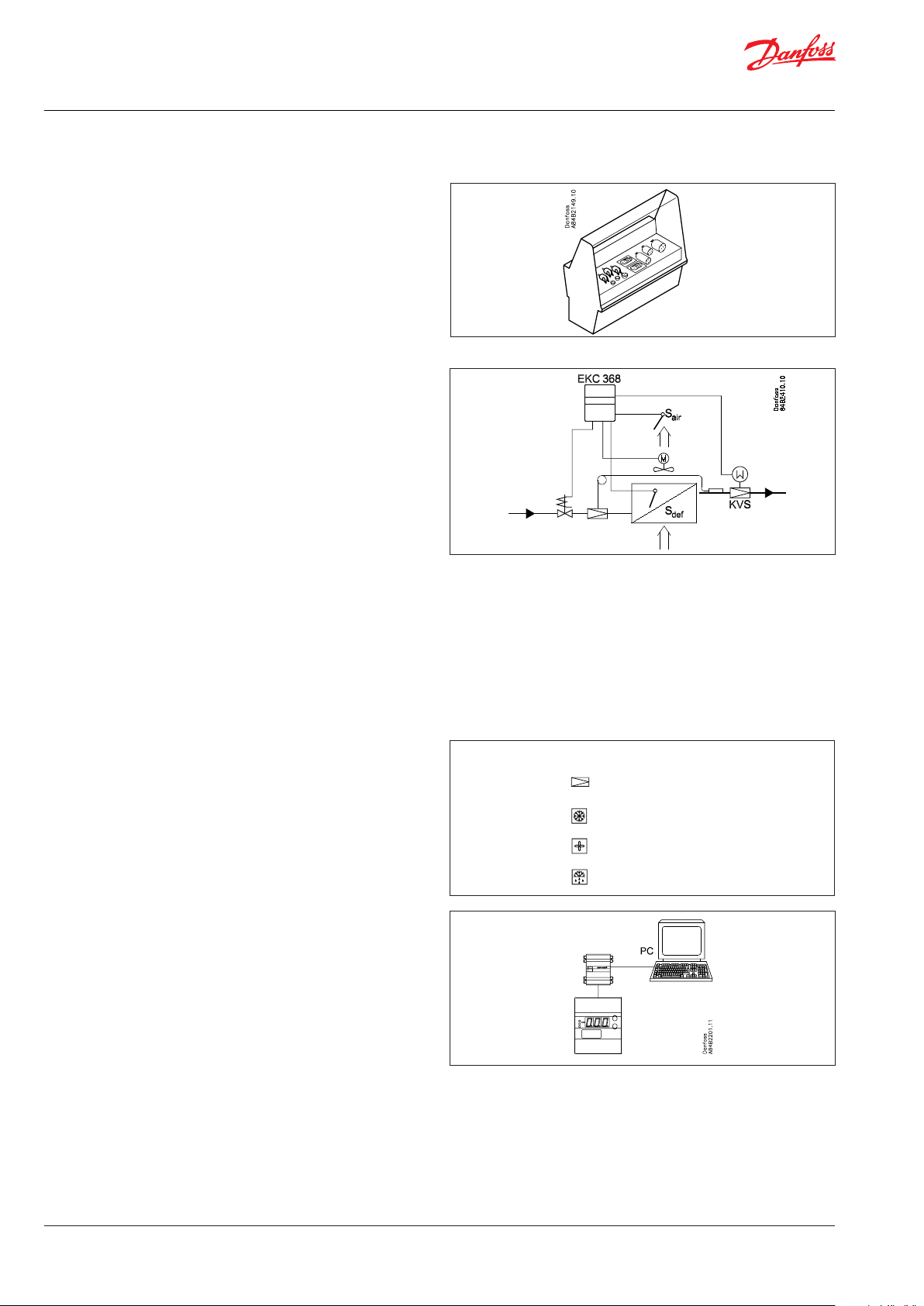
System
A KVS valve is used. The capacity determines the size of it.
A solenoid valve is mounted in the liquid line which is to close
when the controller stops refrigeration.
Sensor S
evaporator.
Advantages
y Wastage is reduced because the air humidity around the pro-
y The temperature is kept within an accuracy of ±0.5°C or better
y A transient phenomenon can be controlled with the adaptive
y Defrost sensor, so that the defrost time will be as short as
y PID regulation
must be placed in the cold air current after the
air
ducts is kept as high as possible
after a transient phenomenon
function so that temperature variations is kept on a minimum
possible
Functions
y Modulating temperature control
y Defrost function: electricity, hotgas or natural
y Alarm if the set alarm limits are exceeded
y Relay outputs for defrost function, solenoid valve, fan and
alarmgiver
y Input signal that can displace the temperature reference
Extra options
y PC operation
The controller can be provided with data communication, so
that it may be hooked up with other products in the
ADAP-KOOL® range of refrigeration controls.
Operation, monitoring and data collection can then be
performed from a PC - either in situ or at a service company.
LED's on front panel
KVS - signal
Refrigeration
Fan
Defrost
2 DKRCC.PS.RP0.B1.02 / 520H9697 © Danfoss A/S (DCS-IMCGPD/sw), 2015-02
Page 3
Manual Electronic media temperature controller, type EKC 368
Function
Very accurate temperature control
With this system where controller and valve have been adapted
for optimum use in the refrigerating plant, the refrigerated
products may be stored with temperature uctuations of less than
±0.5°C.
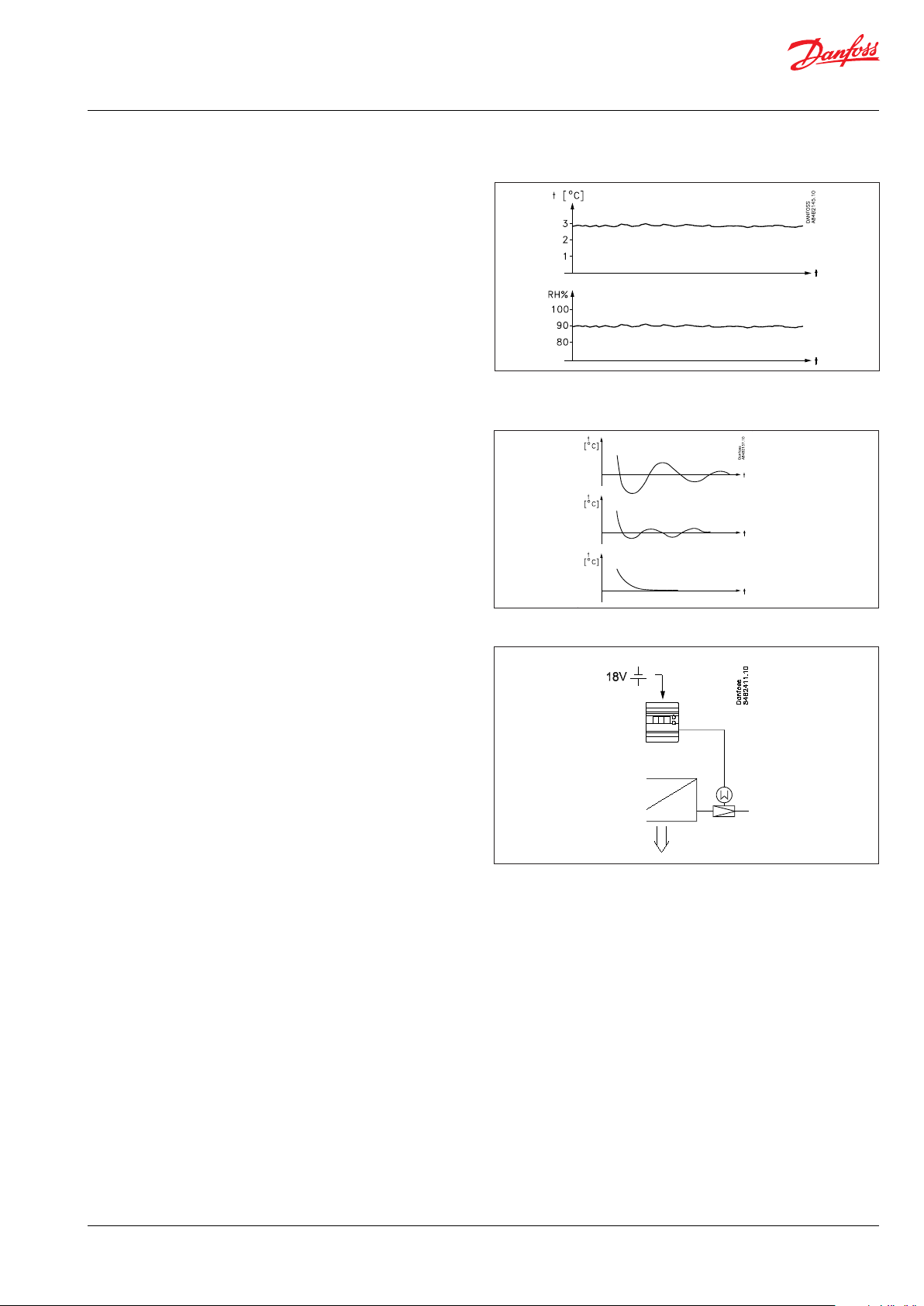
High air humidity
As the evaporating temperature is constantly adapted to the
refrigeration needs and will always be as high as possible with
very small temperature uctuations, the relative air humidity in
the room will be kept at a maximum.
Drying-out of products will therefore be reduced to a minimum.
Temperature is quickly attained
With the built-in PID control and the possibility of choosing
between three transient phenomena, the controller can be
adapted to a kind of temperature performance that is optimum
for this particular refrigerating plant.
y Fastest possible cooling
y Cooling with less underswing
y Cooling where underswing is unwanted
Valve
The valve is an evaporating pressure valve and is available in
several capacity sizes.
The valve is mounted on a step engine which receives impulses
from the controller.
The controller is adapted to this valve.
There is therefore only very few settings for the valve.
In case of power failure that valve's opening degree will be
maintained. If the application requires the valve open in this
situation a battery can be connected to the controller.
© Danfoss A/S (DCS-IMCGPD/sw), 2015-02 DKRCC.PS.RP0.B1.02 / 520H9697 3
Page 4
Manual Electronic media temperature controller, type EKC 368
Data
Supply voltage
Power consumption
Input signal
*) Ri = 100 KΩ
Sensor input 2 pcs. Pt1000 ohm
Relay output 3 pcs. SPST
Alarm relay 1 pcs. SPST
Step motor output Pulsating 100 mA
Data communication Possible to connect a data communication module
Ambient
temperature
Enclosure IP 20
Weight 300 g
Mounting DIN rail
Display LED, 3-digits
Terminals max. 2.5 mm2 multicore
Approvals
If battery backup is used:
Requirements to battery: 18 V DC min. 100 mAh
24 V AC +/-15% 50/60 Hz, 10 VA
(the supply voltage is galvanically separated from the
input and output signals)
Controller
KVS-step motor
Voltage signal* 0 – 10 V or 2 – 10 V
Digital input from external contact function
Short-circuit (pulse signal) of 18 – 20 will start a defrost
During operation
During transport
EU Low Voltage Directive and EMC demands re
CE-marking complied with
LVD-tested acc. to EN 60730-1 and EN 60730-2-9
EMC-tested acc. to EN50081-1 and EN 50082-2
5 VA
1.3 VA
AC-1: 4 A (ohmic)
AC-15: 3 A (inductive)
-10 – 55°C
-40 – 70°C
Ordering
Typ e Function Code No.
EKC 368 Evaporating pressure controller 084B7079
EKA 172 Realtime clock 084B7069
EKA 174 Data communication module (accessories),
(RS 485 module) with galvanic separation
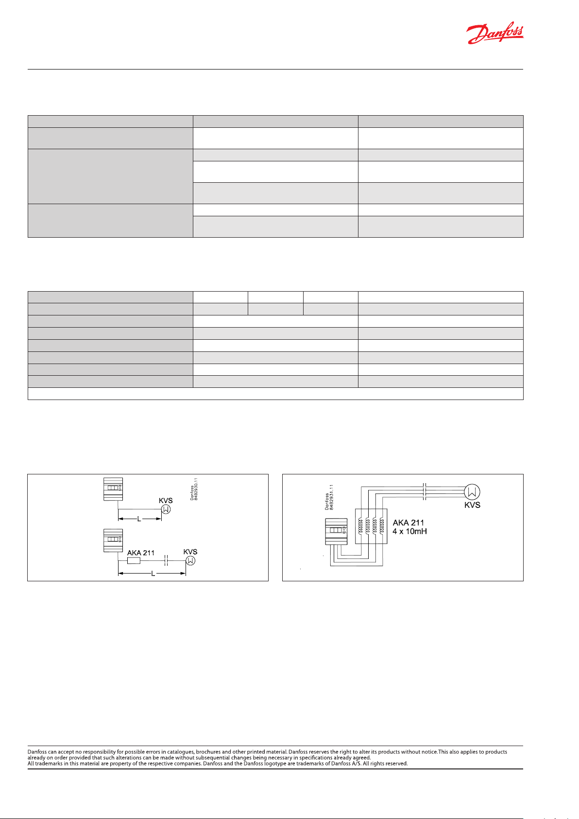
AKA 211 Filter : 4 x 10 mH 084B2238
Temperature sensor Pt1000 ohm: Kindly refer to catalogue RK0YG...
Valves: Kindly refer to catalogue RK0YG...
084B7124
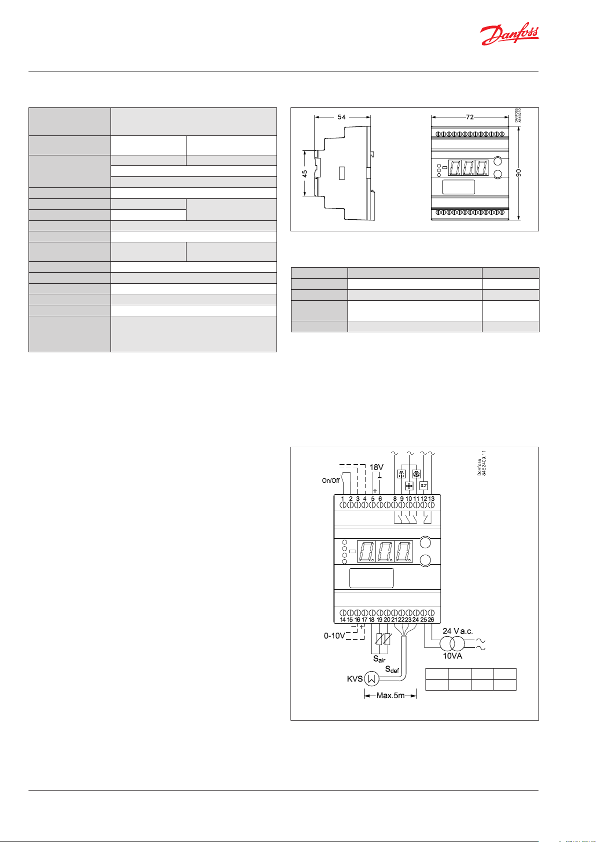
Connections
Necessary connections
Terminals:
25 – 26 Supply voltage 24 V AC
18 – 19 Pt1000 sensor at evaporator outlet
21 – 24 Supply to step motor
1 – 2 Switch function for start/stop of regulation. If a switch is
not connected, terminals 1 and 2 must be short circuited
5 – 6 Battery (the voltage will open the KVS valve if the
controller loses its supply voltage)
Application dependent connections
Terminal:
12 – 13 Alarm relay
There is connection between 12 and 13 in alarm situations
and when the controller is dead
8 – 9 Relay switch for start/stop of defrost
8 – 10 Relay switch for start/stop of fan
8 – 11 Relay switch for start/stop of cooling
16 – 17 Voltage signal from other regulation (Ext.Ref.)
If the voltage signal is received from a PLC or the like,
a data communication module, if any, must be with
galvanic separation.
18-20 Pt1000 sensor for defrost function.
Short-circuit of the terminals for two seconds
(pulse signal) will start a defrost
3-4 Data communication
Mount only, if a data communication module has been
mounted
It is important that the installation of the data communi
cation cable be done correctly.
Cf. separate literature No. RC8AC...
Data communication
21 22 23 24
white black green red
L > 5 m, see page 12
4 DKRCC.PS.RP0.B1.02 / 520H9697 © Danfoss A/S (DCS-IMCGPD/sw), 2015-02
Page 5
Manual Electronic media temperature controller, type EKC 368
Survey of functions
Function Parameters Parameter by operation via data communication
Normal display
Normally the temperature value is shown from room
temperature Sair.
The temperature at the defrost sensor can be displayed by giving
the lower button a brief push (1s).
Reference
Reference
Regulation is based on the set value provided that there is no
external contribution (o10).
(Push both buttons simultaneously to set the setpoint).
Temperature unit
Here you select whether the controller is to indicate the
temperature values in °C or in °F.
If indication in °F is selected, other temperature settings will also
change over to Fahrenheit, either as absolute values or as delta
values.
External contribution to the reference
This setting determines how large a contribution is to be added to
the set reference when the input signal is max. (10 V ).
Correction of signal from Sair
(Compensation possibility through long sensor cable).
Correction of signal from Sdef
(Compensation possibility through long sensor cable).
Start/stop of refrigeration
With this setting refrigeration can be started and stopped.
Start/stop of refrigeration can also be accomplished with the
external switch function. See also appendix 1.
Alarm
The controller can give alarm in dierent situations. When there
is an alarm all the light-emitting diodes (LED) will ash on the
controller front panel, and the alarm relay will cut in.
Alarm for upper deviation
The alarm for too high Sair temperature is set here.
The value is set in Kelvin.
The alarm becomes active when the Sair temperature exceeds the
actual reference plus A01.
(The actual reference (SP + r06) can be seen in u02).
Alarm for lower deviation
The alarm for too low Sair temperature is set here.
The value is set in Kelvin.
The alarm becomes active when the Sair temperature drops below
the actual reference minus A02.
Alarm delay
If one of the two limit values is exceeded, a timer function will
commence. The alarm will not become active until the set time
delay has been passed. The time delay is set in minutes.
Battery alarm
Here it is dened whether the controller has to monitor the voltage
from the battery backup.
If there is low voltage or none at all an alarm will be given.
With data communication the importance of the individual alarms can be defined. Setting is carried out in the “Alarm destinations” menu.
See also page 14.
r05
r06 ExtRefOffset
r09 Adjust SAir
r11 Adjust SDef
r12 Main switch
A01 Upper offset
A02 Lower offset
A03 TempAlrmDel
A34 Batt. alarm
u01 Air temp
u09 Sdef temp
- Temp Setpoint
Temp unit
°C = 0, °F = 1
(In AKM only bar is displayed, whatever the setting)
© Danfoss A/S (DCS-IMCGPD/sw), 2015-02 DKRCC.PS.RP0.B1.02 / 520H9697 5
Page 6

Manual Electronic media temperature controller, type EKC 368
Survey of functions
Function Parameters Parameter by operation via data communication
Defrost
A defrost can be dened in three ways:
- via the data communication from a defrost table
- via short-circuiting of the Sdef sensor
(pulse signal of 2 sec. duration)
- mounting of real time clock module
Defrost is stopped when the temperature at the defrost sensor
reaches the set value or when the set time expires.
Temperature alarms are not active during defrost.
Defrost method
Here you have to set whether defrost is to be carried out with
electricity or hotgas. During defrost the defrost relay will be
operated and the cold relay cut out.
If ELECTRICITY is used, the valve will be open during defrost.
When GAS is used, the valve will be closed during defrost.
Defrost stop temperature
The temperature value is set.
If a defrost sensor has not been mounted, defrost will be stopped on
the basis of time. See later.
Max. defrost duration
If you have chosen to stop defrost based on temperature, this
setting will constitute a safety period where defrost will be stopped,
if it has not occurred based on temperature.
If you have not mounted a defrost sensor, this setting will be the
defrost time.
Drip-o time
Here you set the time that is to elapse from the end of a defrost and
until refrigeration is to be resumed.
(The time when water is dripping o the evaporator).
Delayed fan start after defrost
Here you set the time to elapse from refrigeration may be started
after a defrost and until the fan may be started again.
(The time where the water is “bound” to the evaporator).
Fan start temperature
The fan may also be started a little earlier than mentioned under
“Delayed fan start after defrost” if the defrost sensor registers a
permissible value.
Here you can set the value for when the fan may start.
Fan cut in during defrost
Here you set whether the fan is to operate during defrost.
Delayed temperature alarm after defrost
During and immediately after a defrost the temperature is
“too high”. The “high temperature alarm” can be suppressed right
after a defrost.
Here you must set for how long the alarm is to be suppressed.
The time counts from the start of refrigeration.
If you wish to start an extra defrost, push the lower button for seven
seconds.
If you keep it depressed for seven seconds when a defrost is going
on, the defrost will be stopped.
The drip-o time and the fan delay will be completed.
If you wish to see the temperature at the defrost sensor, push the
lower button briey (1s).
d01
d02 Def. Stop Temp
d04 Max Def.time
d06 DripOfftime
d07 FanStartDel
d08 FanStartTemp
d09 FanDuringDef
d11 Pulldown del
Defrost mode
off = 0
El = 1
Gas = 2
Def. start
Here you can start a manual defrost
u09 Sdef temperature
6 DKRCC.PS.RP0.B1.02 / 520H9697 © Danfoss A/S (DCS-IMCGPD/sw), 2015-02
Page 7

Manual Electronic media temperature controller, type EKC 368
Survey of functions
Function Parameters Parameter by operation via data communication
Control parameters
Actuator type
Here you dene the actuator mounted in the system:
1: KVS 15 - 22
2: KVS 38 - 35
3: KVS 42 - 54
4: User-dened (engine data can be changed via the AKM
programme Danfoss only)
Change of setting only when r12 = o.
P: Amplication factor Kp
If the Kp value is reduced the regulation becomes slower.
I: Integration time Tn
IThe I-setting can be cancelled by setting the value to max. (600s).
If it is set to 600s, parameter n07 must be set to “0”.
(If the Tn value is increased the regulation becomes slower).
D: Dierentiation time Td
The D-setting can be cancelled by setting the value to min. (0).
Transient phenomenon
If the refrigeration requires a very fast transient phenomenon or
must not have an underswing or temperature shift, this function can
be used.
0: Fastest possible cooling
1: Cooling with less underswing
2: Cooling where underswing is unwanted
Start-up after hotgas defrost
The KVS valve must be open before the solenoid valve for
refrigeration may be opened.
Here you set how much time the valve needs for opening.
The period of time starts when the drip-o time has ended.
Miscellaneous
Input signal
If you wish to connect a signal that is to displace the controller’s
control reference, the signal must be dened in this menu.
0: No signal
1: 0 - 10 V
2: 2 - 10 V
(0 or 2 V will not give a displacement.
10 V will displace the reference by the value set in menu r06).
Frequency
Set the net frequency.
Address
If the controller is built into a network with data communication,
it must have an address, and the master gateway of the data
communication must then know this address.
These settings can only be made when a data communication
module has been mounted in the controller and the installation of
the data communication cable has been completed.
This installation is mentioned in a separate document “RC.8A.C”.
The address is set between 1 and 60. o03
The address is sent to the gateway when the menu is set in pos.
ON (The setting will automatically change back to O after a few
seconds).
n03 Valve type
n04 Kp factor
n05
n06 Td sec.
n07 Ctrl. mode
n08 Open time
o10 AI type
o12
o04
Tn sec.
50/60 Hz
(50 = 0, 60 = 1)
Following installation of a data communication
module, the controller can be operated on a par with
the other controllers in ADAP-KOOL® refrigeration
controls
© Danfoss A/S (DCS-IMCGPD/sw), 2015-02 DKRCC.PS.RP0.B1.02 / 520H9697 7
Page 8

Manual Electronic media temperature controller, type EKC 368
Survey of functions
Function Parameters Parameter by operation via data communication
Service
A number of controller values can be printed for use in a service
situation.
Read the temperature at the Sair sensor
(calibrated value).
Read the control reference
(Set reference + any contribution from external signal).
Read value of external voltage signal u07 AI Volt
Read temperature at the Sdef sensor
(calibrated value).
Read status of input DI
(start/stop input).
Read the duration of the ongoing defrost
or the duration of the last completed defrost.
Read opening degree of the valve in % u23 KVS OD %
Operating status
The controller goes through some regulating situations where it is
just waiting for the next point of the regulation. To make these
“why is nothing happening” situations visible, you can see an
operating status on the display. Push briey (1s) the upper button.
If there is a status code, it will be shown on the display. (Status codes
have lower priority than alarm codes. In other words, you cannot see
a status code, if there is an active alarm).
The individual status codes have the following meanings:
S4: Defrost sequence.
The evaporator drips o and waits for the time to run out.
S10: Refrigeration stopped by the internal or external start/ stop. 10
S12: Refrigeration stopped due to low Sair. 12
S13: Defrost sequence. The KVQ valve is closing. 13
S14: Defrost sequence. Defrost in progress. 14
S15: Defrost sequence. The fan waits for the time to run out. 15
u01 Air temp.
u02 Air ref.
u09 Sdef temp
u10 DI status
u11 Defrost time
Alarm relay
--
-- Cooling rel.
-- Fan relay
-- Def. relay
Read status of alarm relay
ON is operating status with alarm
Read status of relay for solenoid valve
Read status of relay for fan
Read status of relay for defrost
Ctrl state
(0 = regulation)
4
8 DKRCC.PS.RP0.B1.02 / 520H9697 © Danfoss A/S (DCS-IMCGPD/sw), 2015-02
Page 9

Manual Electronic media temperature controller, type EKC 368
Operation Menu survey
Display
The values will be shown with three digits, and with a setting you
can determine whether the temperature are to be shown in °C or
in °F.
Light-emitting diodes (LED) on front panel
There are LED’s on the front panel which will light up when the
belonging relay is activated.
The three lowermost LED’s will ash, if there is an error in the
regulation.
In this situation you can upload the error code on the display and
cancel the alarm by giving the uppermost button a brief push.
The controller can give the following messages
E1
E6 Change battery in timer. Set the timer
Error message
E7 Cut-out Sair
E8 Short circuited Sair
E12 Analog input signal is outside the range
A1
A2 Low-temperature alarm
Alarm message
A43 Check supply voltage for the step engine
A44 Battery alarm (no voltage or too low voltage)
Errors in the controller
High-temperature alarm
The buttons
When you want to change a setting, the two buttons will give you
a higher or lower value depending on the button you are pushing.
But before you change the value, you must have access to the
menu. You obtain this by pushing the upper button for a couple
of seconds - you will then enter the column with parameter
codes. Find the parameter code you want to change and push
the two buttons simultaneously. When you have changed the
value, save the new value by once more pushing the two buttons
simultaneously.
Gives access to the menu (or cutout an alarm)
Gives access to changes
Saves a change
Examples of operations
Set reference temperature
1. Push the two buttons simultaneously
2. Push one of the buttons and select the new value
3. Push both buttons again to conclude the setting
Set one of the other menus
1. Push the upper button until a parameter is shown
2. Push one of the buttons and nd the parameter you want to
change
3. Push both buttons simultaneously until the parameter value is
shown
4. Push one of the buttons and select the new value
5. Push both buttons again to conclude the setting
SW =1.6x
180
min
180
min
20
min
20
min
199
min
20
min
Fac.
setting
30
45
90
Function Param. Min. Max.
Normal display
Shows the temperature at the room sensor - °C
Give the lower button a brief push to see
the temperature at the defrost sensor
Reference
Set the required room temperature - -70°C 160°C 10
Temperature unit r05 °C °F °C
External contribution to the reference r06 -50 K 50 K 0
Correction of the signal from Sair r09 -10.0 K 10.0 K 0
Correction of the signal from Sdef r11 -10.0 K 10.0 K 0
Start/stop of refrigeration r12 OFF On On
Alarm
Upper deviation (above the temperature
setting)
Lower deviation (below the temperature
setting)
Alarm’s time delay A03 0
Monitoring of battery A34 Off On Off
Defrost
Defrost method (ELECTRICITY/GAS) d01 Off GAS Off
Defrost stop temperature d02 0 25°C 6
Max. defrost duration d04 0
Drip-o time d06 0
Delay for fan start or defrost d07 0
Fan start temperature d08 -15°C 0°C -5
Fan cut in during defrost (yes/no) d09 no yes no
Delay for temperature alarm after defrost d11 0
Regulating parameters
Actuator type: 1 = KVS15-22, 2 = KVS28-35,
3 = KVS42-54 4 = User dened via AKM
/ For Danfoss only Setting of menu only
when r12 = o.
P: Amplication factor Kp n04 1 50 4
I: Integration time Tn (600 = o ) n05 60 s 600 s 120
D: Dierentiation time Td (0 = o ) n06 0 s 60 s 0
Transient phenomenon
0: Fast cooling
1: Cooling with less underswing
2: Cooling where underswing is unwanted
Start-up time after hotgas defrost n08 0 min
Miscellaneous
Controller’s address o03*) 1 60 0
ON/OFF switch (service-pin message) o04*) - - Off
Dene input signal of analog input
0: no signal
1: 0 – 10 V
2: 2 – 10 V
Set supply voltage frequency o12 50 Hz 60 Hz 50
Service
Read temperature at the Sair sensor u01 °C
Read regulation reference u02 °C
Read value of external voltage signal u07 V
Read temperature at the Sdef sensor u09 °C
Read status of input DI u10 on/off
Read duration of defrost u11 m
Opening degree of the valve u23 %
*) This setting will only be possible if a data communication module has been installed in
the controller.
- °C
A01 0 50 K 5
A02 0 50 K 5
n03 1 4 1
n07 0 2 1
o10 0 2 0
0
0
1
© Danfoss A/S (DCS-IMCGPD/sw), 2015-02 DKRCC.PS.RP0.B1.02 / 520H9697 9
Page 10

Manual Electronic media temperature controller, type EKC 368
Start of controller Fine adjustments
When the electric wires have been connected to the controller,
the following points have to be attended to before the regulation
starts:
1. Switch o the external ON/OFF switch that starts and stops the
regulation
2. Follow the menu survey on page 8, and set the various
parameters to the required values
3. Switch on the external ON/OFF switch, and regulation will start
4. If the system has been tted with a thermostatic expansion
valve, it must be set to minimum stable superheating
5. Follow the actual room temperature on the display.
(Use a data collection system, if you like, so that you can follow
the temperature performance)
If the temperature uctuates
When the refrigerating system has been made to work steadily,
the controller’s factory-set control parameters should in most
cases provide a stable and relatively fast regulating system.
If the system on the other hand oscillates, you must register the
periods of oscillation and compare them with the set integration
time Tn, and then make a couple of adjustments in the indicated
parameters.
If the time of oscillation is longer than the integration time:
(Tp > Tn , (Tn is, say, 4 minutes))
1. Increase Tn to 1.2 times T
p
2. Wait until the system is in balance again
3. If there is still oscillation, reduce Kp by, say, 20%
4. Wait until the system is in balance
5. If it continues to oscillate, repeat 3 and 4
When the system has been operating for a while, it may be
required for some systems to optimise some of the adjustments.
Below we have a look at settings having an inuence on the speed
and accuracy of the regulation.
Method for xing Kp, Tn and T
d
Described below is a method (Ziegler-Nichols) for xing Kp, Tn and
Td.
1. The system is made to regulate the temperature at the required
reference with a typical load. It is important that the valve
regulates, and that it is not fully open
The controller is set, so that it will regulate as a P-controller.
(Td is set to 0, Tn in pos. OFF (600), and Q-Ctrl.mode (n07)
is set at 0)
The stability of the system is examined by stopping the system
for, say, one minute (using the start/stop setting or the switch).
Now check how the building-up of the temperature proceeds.
If the building-up peters out, raise Kp a little and repeat the
start/stop operation. Continue with this until you obtain a
building-up which does not peter out
2. Kp is in this case the critical amplication (K
pcritical
) and the
building-up time for the continued oscillation is the critical
building-up time (T
critical
)
3. Based on these values, the regulating parameters can now be
calculated and subsequently set:
y If PID regulation is required:
Kp < 0,6x K
Tn > 0,5x T
Td < 0,12x T
pcritical
critical
critical
y If PI regulation is required:
Kp < 0,45x K
Tn > 0,85x T
pcritical
critical
6. Reset value for “Q-Ctrl.mode” (n07)
If the time of oscillation is shorter than the integration time:
(Tp < Tn , (Tn is, say, 4 minutes))
1. Reduce Kp by, say, 20% of the scale reading
2. Wait until the system is in balance
3. If it continues to oscillate, repeat 1 and 2
10 DKRCC.PS.RP0.B1.02 / 520H9697 © Danfoss A/S (DCS-IMCGPD/sw), 2015-02
Page 11

Manual Electronic media temperature controller, type EKC 368
Data communication
This page contains a description of a few of the possibilities
you will have when the controller is provided with data
communication.
Each controller is provided
with a plug-in module.
The controllers are then
connected to a two-core cable.
Up to 60 controllers may be
connected to one cable.
This cable is also connected to
a gateway type AKA 243.
This gateway will now control
the communication to and
from the controllers.
It will collect temperature
values and it will receive
alarms. When there is an
alarm the alarm relay will be
activated for two minutes.
If you want to know more about operation of controllers via PC,
you may order additional literature.
The gateway can now be
connected to a modem.
When an alarm occurs from
one of the controllers, the
gateway will, via the modem,
make a phone call to the
service company.
At the service company a
modem, gateway and PC with
system software type AKM
have been installed.
All the controllers’ functions
can now be operated from the
various menu displays.
The programme will for
example upload all the
collected temperature values
once a day.
Example of menu display
y Measurements are shown at
one side and settings at the
other
y You will also be able to see
the parameter names of the
functions on page 4 – 7
y With a simple change-over
the values can also be
shown in a trend diagram
y If you wish to check earlier
temperature measurements,
you can see them in the log
collection
Alarms
If the controller is extended
with data communication, it
will be possible to dene the
importance of the transmitted
alarms.
The importance is dened with
the setting: 1, 2, 3 or 0.
When the alarm then arises at
some time, it will result in one
of the following activities:
1 = Alarm
The alarm message is sent o
with alarm status 1.
This means that the gateway
that is the master in the
system will have its alarm
relay output activated for two
minutes. Later, when the alarm
ceases, the alarm text will be
retransmitted, but now with
status value 0.
2 = Message
The alarm text is transmitted
with status value 2.
Later, when the “message”
lapses, the alarm text is
retransmitted, but now with
status value 0.
3 = Alarm
As “1”, but the master gateway’s
relay output is not activated.
0 = Suppressed information
The alarm text is stopped at
the controller.
It is transmitted nowhere.
© Danfoss A/S (DCS-IMCGPD/sw), 2015-02 DKRCC.PS.RP0.B1.02 / 520H9697 11
Page 12
Manual Electronic media temperature controller, type EKC 368
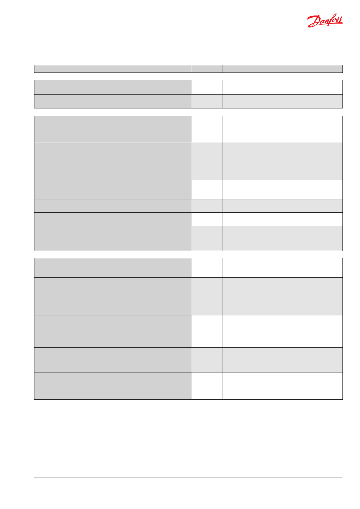
Trouble shooting
In addition to the error messages transmitted by the controller, the table below may help identifying errors and defects.
Symptom Defect Conrmation of defect
Evaporator blocked with ice.
Defrost function in order
Evaporator blocked with ice.
Defrost function not in order
Defrost period too long
Appendix 1
Interaction between internal and external start/stop functions and active functions.
Internal Start/stop O O On On
External Start/stop O On O On
Refrigeration O On
Fan relay O On
Expansion valve relay O On
Defrost relay On/o On/o
Temperature monitoring No Ye s
Sensor monitoring Yes Yes
If a start/stop function is put in pos. OFF during a defrost, the defrost will be carried out as planned
Defrost set incorrectly, or placing of Sdef is
not correct
Defrost sensor Sdef cut out Check sensor
Defrost sensor Sdef is short-circuited
Heating element is not cut in
Defrost set incorrectly Check setting of the stop temperature
Defrost continues beyond the set stop
temperature
Check setting / check sensor location
Check if the function that starts defrost is
stuck
Check the heating element and the defrost
relay
Check location of Sdef
KVS connection
If the distance between EKC 368 and the KVS valve exceeds 5 m a lter must be mounted to obtain the correct valve function.
L < 5 m
5 m < L < 50 m
12 DKRCC.PS.RP0.B1.02 / 520H9697 © Danfoss A/S (DCS-IMCGPD/sw), 2015-02
 Loading...