


User Guide
Interface
EKC 366
The controller is used for regulating a valve in
a refrigerating system - for example in
connection with:
• Long-term storage of fruits and vegetables
• Refrigerating plant
• Brewery systems
• Processing plant
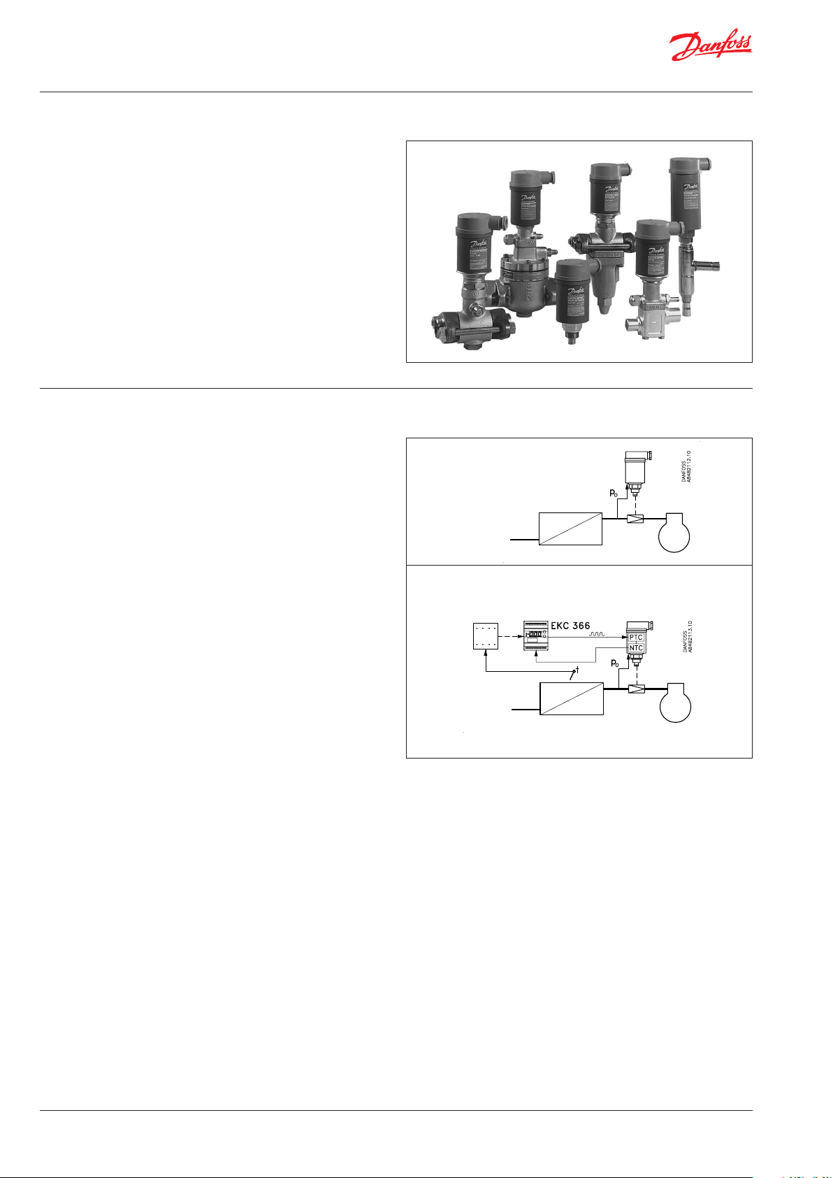
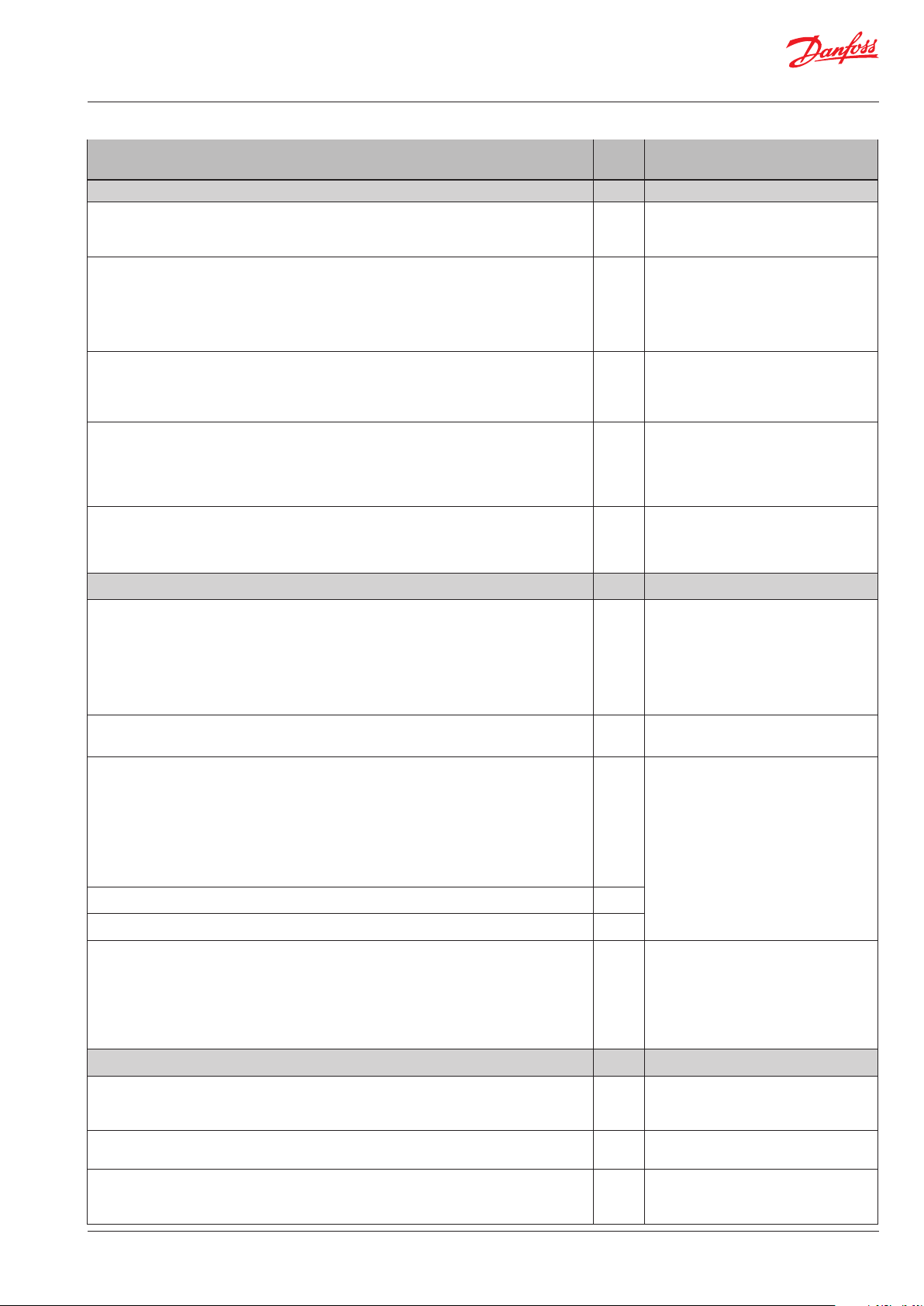
Application Here the controller has been specially
designed for the following functions:
Maintenance of a constant
evaporating pressure
A temperature sensor in the valve’s actuator will
regulate its temperature. This temperature is
an indication of the pressure in the valve, and
the interface module will keep this temperature
constant.
The media temperature is regulated
by a PLC or similar device
Here the interface module receives a variable
signal from the PLC and will subsequently
regulate the valve, so that the refrigeration will
be as accurate as possible.
PLC
© Danfoss | DCS (ADAP-KOOL®) |2015-11
DKRCI.PS.RP0.C1.02 | 1
User Guide | Interface, EKC 366
System
The controller must always be used in conjunction with a pilot
valve of the types shown here.
The most commonly used one is pilot valve CVQ in conjunction
with main valve PM3 (sketched out above).
Valve types:
- CVQ + PM
- KVQ
- TQ
- PHTQ
- TEAQ
- CVMQ
Function
The valve constantly receives feedback of the pressure in the
evaporator. Whatever the variations in the suction pressure from
the compressor, this feedback will produce the result that the
evaporating pressure is kept constant.
In conjunction with the controller, an electronic constant-pressure
valve is thus obtained.
Inserted between the controller and the actuator is a so-called
inner regulating loop. This loop will - via an NTC resistance - constantly control the temperature in the actuator.
In an application where a PLC or similar device is used for regulating a media temperature, the regulating system will in this way be
supplied with an outer regulating loop - which will result in great
regulating accuracy.
"Q valve"
PLC
© Danfoss | DCS (ADAP-KOOL®) | 2015-11
DKRCI.PS.RP0.C1.02 | 2
User Guide | Interface, EKC 366
Survey of functions
Function Para-
meter
Temperature regulation Actuator temperature
Display of valve temperature
The display constantly shows the valve's temperature.
The display is ltered over a period of approx. 10 seconds
Valve’s basic temperature reference
This temperature setting is the valve’s basic setting. At this value no signal must be
received from an external regulation.
The setting value is taken from one of the curves shown and may be ne-adjusted later when the valve has reached the temperature (read the manometer in the system).
(Push both buttons simultaneously to set the menu)
Temperature unit
Set here whether the controller is to show the temperature values in °C or in °F. If indication in °F is selected, other temperature settings will also change over to Fahrenheit, either as absolute values or as delta values.
Input signal’s temperature inuence
This setting determines how much the input signal has to raise the temperature in
the valve. You should aim at selecting the value, so that the valve can close at the
highest occurring evaporating pressure when the input signal is maximum (value to
be set in Kelvin)
Reference
The valve’s temperature is regulated on the basis of the basic setting plus the signal
from the external regulation. (Reference = SP Temp + percentage of "r06".)
The reference can be seen when you push the lower of the two buttons
Sundry congurations Miscellaneous
Parameter by operation via data
communication
- Actuator temp.
- SP Temp.
r05 Temp. unit (°C=0, °F=1)
(In AKM only °C is displayed, whatever
the setting).
r06 Ext.Ref.oset K
- Actuator Ref.
External signal
Here you set the signal that is to be connected to the controller.
0: no signal
1: 4-20 mA
2: 0-20 mA
3: 0-10 V
4: 2-10 V
Frequency
Set network frequency
Data communication
If the controller is built into a network with data communication, it must have an
address, and the master gateway of the data communication must then know this
address.
These settings can only be made when a data communication module has been
mounted in the controller and the installation of the data communication cable has
been completed.
This installation is mentioned in a separate document “RC.8A.C”.
The address is set between 1 and 60 o03
The address is sent to the gateway when the menu is set in pos. ON o04
Language
This setting is only required when data communication is connected to the controller.
Settings: 0=English, 1=German, 2=French, 3=Danish, 4=Spanish, and 6= Swedish
When the controller is operated via data communication, the texts in the right-hand
column will be shown in the selected language.
When you change the setting to an other language you must activate o04 before "the
new language" can be visible from the AKM program.
Service
o10 AI Type
o12 50 / 60 Hz
o11 Language
(50=0, 60=1)
Following installation of a data communication module, the controller can
be operated on a par with the other
controllers in ADAP-KOOL® refrigeration controls.
The signal will be constantly updated. If you wish to follow the signal beyond the
20 seconds, the time-out period, push one of the two buttons before the time-out
period expires
External current signal
Here you can read the value of the current signal received by the controller at its input
External voltage signal
Here you can read the value of the voltage signal received by the controller at its
input
© Danfoss | DCS (ADAP-KOOL®) | 2015-11
u06 AI mA
u07 AI Volt
DKRCI.PS.RP0.C1.02 | 3

User Guide | Interface, EKC 366
Operation
Display
The values will be shown with three digits, and with a setting you
can determine whether they are to be shown in °C or in °F.
LED’s on the front panel
There is one LED on the front panel which will light up when
power is sent to the pilot valve.
There are furthermore three LED’s which will ash if there is an
error in the regulation. In this situation you can show the error
code on the display and cut out the alarm by giving the upper
button a brief push.
The controller can give the following messages:
E1 Errors in the controller
E11 Valve’s actuator temperature outside its range
E12 Input signal outside its range
The buttons
When you want to change a setting, the two buttons will give you
a higher or lower value depending on the button you are pushing. But before you change the value, you must have access to the
menu. You obtain this by pushing the upper button for a couple
of seconds - you will then enter the column with parameter codes.
Find the parameter code you want to change and push the two
buttons simultaneously. When you have changed the value, save
the new value by once more pushing the two buttons simultaneously.
Menu survey
Function
Read valve’s actual temperature (standard display) -
Set valve’s basic temperature reference - 40.0°C 140°C
Read valve’s regulation reference -
Select temperature unit (°C/°F) r05 °C °F
Input signal’s temperature inuence r06 -99.9 K 99.9 K
Controller’s address o03* 1 60
ON/OFF switch (service-pin message) o04* - -
Dene input signal
0: no signal
1: 4 - 20 mA
2: 0 - 20 mA
3: 0 - 10 V
4: 2 - 10 V
Language (0=English, 1=German, 2=french, 3=Danish,
4=Spanish, 6=Swedish). When you change this setting
you must also activate o04.
Set supply voltage frequency o12 50 Hz 60 Hz
Service information
Read value of external current signal u06
Read value of external voltage signal u07
*) This setting will only be possible if a data communication module has been
installed in the controller.
Factory setting
If you need to return to the factory-set values, it can be done in this way:
- Cut out the supply voltage to the controller
- Keep both buttons depressed at the same time as you recon nect the supply voltage
Parameter
o10 0 4
011* 0 6
SW =1.2x
Min. Max.
°C
°C
mA
V
Gives access to the menu
Gives access to changes
Saves a change
Examples of operations
Set the valve’s basic temperature reference
1. Push the two buttons simultaneously
2. Push one of the buttons and select the new value
3. Push both buttons again to conclude the setting
Read the valve’s regulating reference
1. Push the lower button
(After approx. 20 seconds the controller automatically returns
to its setting, and it again shows the valve’s actual temperature)
Set one of the other menus
1. Push the upper button until a parameter is shown
2. Push one of the buttons and nd the parameter you want to
change
3. Push both buttons simultaneously until the parameter value is
shown
4. Push one of the buttons and select the new value
5. Push both buttons again to conclude the setting
© Danfoss | DCS (ADAP-KOOL®) | 2015-11
DKRCI.PS.RP0.C1.02 | 4

User Guide | Interface, EKC 366
Valve’s working temperature
Without external signal
The working temperature must be set on the basis of one
of the following curves. Find the actuator temperature corresponding to the required evaporating temperature (push).
Set the value in the controller as mentioned under “Set the
valve’s basic temperature reference”.
With external signal
If the valve is to be operated with an external signal, two settings have to be made. One is as mentioned to the left, and the
other determines how much the signal must be able to raise the
temperature in the valve. This value is also read on one of the following curves.
Set the value in the r06 menu.
If the set value is too low, the valve will not be able to close/
open fully.
CVQ KVQ
TQ
All the curves shown are approximate.
Example
CVQ type = 0-6 bar
Refrigerant = R
A constant evaporating temperature or input pressure to the valve of -9°C (2 bar) is
required.
According to the CVQ curve this will require a temperature in the actuator of 80°C.
Set the valve’s basic temperature reference at 80°C.
When the valve has reached its working temperature, it may be necessary to neadjust the setting from the system’s manometer.
717
CVMQ
The two curves are shown with the valve’s spring setting equal-ling the factory
setting. If the spring setting is changed to a higher pressure, the curve will be
displaced correspondingly to a higher temperature.
© Danfoss | DCS (ADAP-KOOL®) | 2015-11
DKRCI.PS.RP0.C1.02 | 5

User Guide | Interface, EKC 366
Data
Supply voltage
Power consumption
Input signal
Actuator
Data communication
Ambient temperature
Enclosure IP 20
Weight 300 g
Mounting DIN rail
Display LED, 3 digits
Terminals max. 2.5 mm2 multicore
Approvals
24 V a.c. +/-15% 50/60 Hz, 80 VA
(the supply voltage is galvanically separated
from the input and output signals)
Controller
Valve
4-20 mA, 0-20 mA, 0-10V d.c. or
2-10 V d.c.
Input
Output
Possible to connect a data communication
module
During operation
During transport
EU Low Voltage Directive and EMC demands re
CE-marking complied with.
LVD-tested acc. to EN 60730-1 and EN 607302-9
EMC-tested acc. to EN 50081-1 and EN 50082-2
5 VA
75 VA
Temperature signal
from sensor in actuator
Pulsating 24 V a.c. to
actuator
-10 - 55°C
-40 - 70°C
Ordering
Type Function Code No.
EKC 366 Interface module 084B7076
EKA 173
EKA 174
Valves: Kindly refer to catalogue RK0YG
Data communication module (ac-
cessories), (FTT 10 module)
Data communication module (ac-
cessories), (RS 485 module)
with galvanic separation
084B7092
084B7124
Connections
Necessary connections
Terminals:
25-26 Supply voltage 24 V a.c. 80 VA
17-18 Signal from NTC sensor in valve
23-24 Supply to valve’s PTC resistance
Control signal, if applicable (see also o10)
Either terminals:
15-16 Voltage signal
or
18-19 Current signal
Data communication, if applicable
Terminals:
3-4 Mount only, if a data communication module has been
mounted.
It is important that the installation of the data communication cable be done correctly. Cf. separate literature No.
RC8AC...
Data communication
© Danfoss | DCS (ADAP-KOOL®) | 2015-11
DKRCI.PS.RP0.C1.02 | 6

User Guide | Interface, EKC 366
Data communication
This page contains a description of a few of the possibilities you
will have when the controller is provided with data communication.
Examples
Each controller is provided
with a plug-in module.
The controllers are then connected to a two-core cable.
Up to 60 controllers may be
connected to one cable.
This cable is also connected to
a gateway type AKA 243.
This gateway will now control
the communication to and
from the controllers.
It will collect temperature values and it will receive alarms.
When there is an alarm the
alarm relay will be activated for
two minutes
If you want to know more about operation of controllers via PC,
you may order additional literature.
The gateway can now be connected to a modem.
When an alarm occurs from
one of the controllers, the
gateway will - via the modem
- make a phone call to the
service company.
At the service company a
modem, gateway and PC
with system software type
AKM have been installed.
All the controllers’ functions
can now be operated from
the various menu displays.
The programme will for
example upload all the collected tempera ture values
once a day.
Example of menu display
Measurements are shown at
one side and settings at the
other.
You will also be able to see the
parameter names of the functions on page 3.
With a simple change-over the
values can also be shown in a
trend diagram.
If you prefer to see the earlier
temperature measurements,
you may upload a log collection.
Alarms
If the controller is extended
with data communication, it
will be possible to dene the
importance of the transmitted
alarms.
The importance is dened with
the setting: 1, 2, 3 or 0. When
the alarm then arises at some
time, it will result in one of the
following activities:
1 = Alarm
The alarm message is sent o
with alarm status 1. This means
that the gateway that is the
master in the system will have
its alarm relay output activated
for two minutes. Later, when
the alarm ceases, the alarm
text will be retransmitted, but
now with status value 0.
2 = Message
The alarm text is transmitted
with status value 2. Later, when
the “message” lapses, the alarm
text is retransmitted, but now
with status value 0.
3 = Alarm
As “1”, but the master gateway’s
relay output is not activated.
0 = Suppressed information
The alarm text is stopped at
the controller. It is transmitted
nowhere.
© Danfoss | DCS (ADAP-KOOL®) | 2015-11
DKRCI.PS.RP0.C1.02 | 7

User Guide | Interface, EKC 366
Danfoss can accept no responsibility for possible errors in catalogues, brochures and other printed material. Danfoss reserves the right to alter its products without notice. This also applies to products
already on order provided that such alternations can be made without subsequential changes being necessary in specications already agreed.
All trademarks in this material are property of the respecitve companies. Danfoss and Danfoss logotype are trademarks of Danfoss A/S. All rights reserved.
© Danfoss | DCS (ADAP-KOOL®) | 2015-11
DKRCI.PS.RP0.C1.02 | 8
 Loading...