

Page 1
Capacity controller
EKC 331T
Manual
Page 2
Introduction
Application
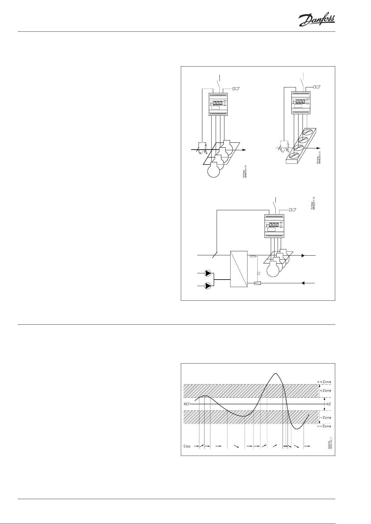
The controller is used for capacity regulation of compressors or
condensers in small refrigerating systems.
Regulation can be carried out with up to four identical capacity
steps.
Advantages
• Patented neutral zone regulation
• Sequential or cyclic operation
Functions
• Regulation
Regulation with up to four relay outputs can be carried out.
Regulation takes place with a set reference which is compared
to a signal from a pressure transmitter or a temperature sensor.
• Relay module
It is possible to use the controller as relay module, so that the
relays are cut in or out by means of an external voltage signal.
• Alarm function
A relay becomes activated when the set alarm limits are exceeded.
• Digital input
The digital input can be used for:
- night operation where the suction pressure is raised
- heat recovery where the condensing pressure is raised
- external start/stop of the regulation.
- Monitoring of safety circuit
• Reverse function
The regulation can be reversed so that the relays are activated
in case of falling temperature, rather than by the rising temperature.
• Possibility of data communication
Display
A signal from a pressure transmitter will always be converted and
shown as a temperature value.
Settings are made as for temperature values.
Function
Capacity regulation
The cut-in capacity is controlled by signals from the connected
pressure transmitter (temperature sensor) and the set reference.
Outside the reference a neutral zone is set where the capacity will
neither be cut in nor out.
Outside the neutral zone (in the hatched areas named +zone and
-zone) the capacity will be cut in or out if the regulation registers
a change of pressure (the temperature) “away” from the neutral
zone. Cutin and cutout will take place with the set time delays.
If the pressure (the temperature) however “approaches” the
neutral zone, the controller will make no changes of the cut-in
capacity.
If regulation takes place outside the hatched area (named ++zone
and --zone), changes of the cut-in capacity will occur somewhat
faster than if it were in the hatched area.
Cutin of steps can be dened for either sequential or cyclic operation.
2 Manual RS8CU502 © Danfoss 08-2012 EKC 331T
Page 3
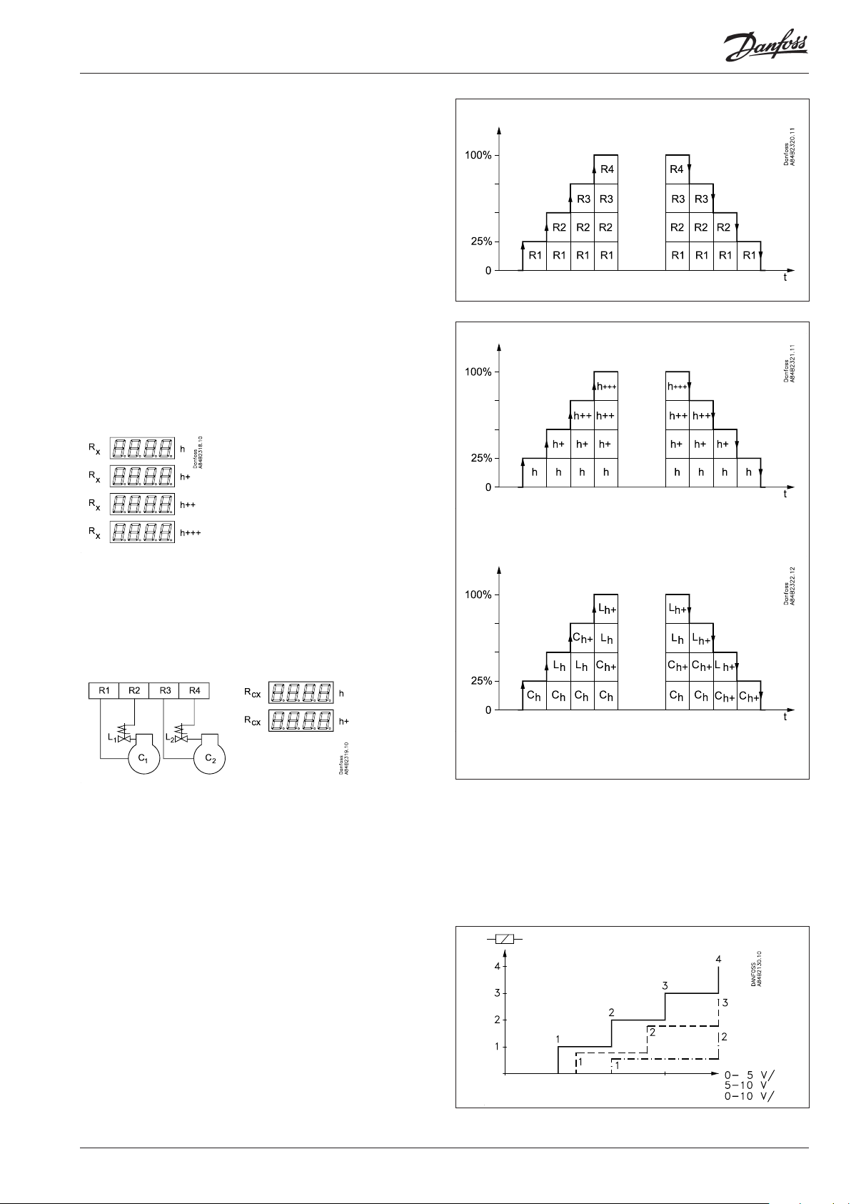
Sequential
The relays are here cut in in sequence – rst relay number 1, then
2, etc.
Cutout takes place in the opposite sequence, i.e. the last cut-in
relay will be cut out rst.
Cyclic
The relays are coupled here so that the operating time of the
individual relays will become equalised.
At each cutin the regulation scans the individual relays’ timer,
cutting in the relay with least time on it.
At each cutout a similar thing happens. Here the relay is cut out
that has most hours on the timer.
Rx = random relay
h = number of hours
If capacity regulation is carried out on two compressors with one
unloader each, the following function can be used:
Relays 1 and 3 are connected to the compressor motor.
Relays 2 and 4 are connected to the unloaders.
Relays 1 and 3 will operate in such a way that the operating time
for the two relays will become equalised.
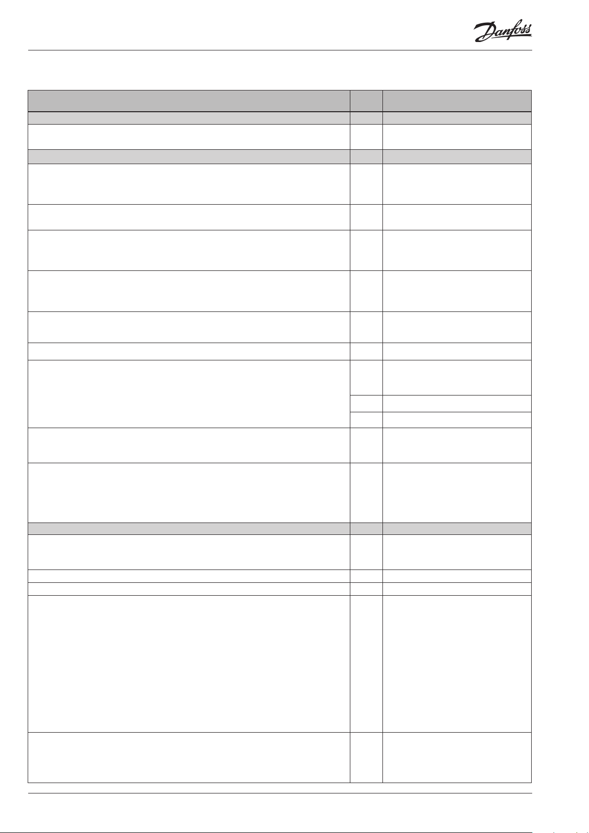
Relay module
The controller can also be used as a relay module where the relays
in the module are operated by the received voltage signal. The
signal must be connected to terminal 15-16.
Depending on the denition of the signal and the number of
relays used, the relays will be ”distributed” over the signal.
A hysteresis at the individual coupling points will ensure that the
relay will not cut in or out when not required.
C = compressor, L = Unloader
EKC 331T Manual RS8CU502 © Danfoss 08-2012 3
Page 4
Suvey of functions
Function Para-
meter
Normal display
Normally the signal from the pressure transmitter/temperature sensor is shown
If the controller is used as relay module, Uin will appear on the display.
Pressure regulation Reference Settings
Regulation setpoint
Regulation is based on the set value.
A change of the set value can be limited/xed by means of the settings in r02 and r03.
(Push both buttons simultaneously to set the menu.)
Neutral zone
There is a neutral zone around the reference. See also page 2.
Start/stop of refrigeration
With this setting the refrigeration can be started and stopped. Start/stop of refrigeration may also be performed with an external contact function connected to the input
named "DI".
Reference
The set reference may be displaced with a xed value when a signal is received at the
DI input. Regulation will then be based on the set point plus the value set here.
(Cf. also Denition of DI input).
Night setback
OFF: No change of the reference
ON: (1) Oset value in "r13" forms part of the reference
The total reference can be seen when you push the lower of the two buttons - Reference
Reference limitation
With these settings the setpoint can only be set between the two values.
(This also apply if regulation with displacements of the reference).
Max. permissible reference value. r25 Max. reference
Parameter by operation via
data communication
Pressure / Temp°C
- Set point°C
r01 Neutral zone
r12 Main switch
r13 Ref. oset
r27 NightSetback
Min. permissible reference value. r26 Min. reference
Correction of temperature measurement
An oset adjustment of the registered temperature can be made. The function is used
if correction for a too long sensor cable has to be made.
Unit
Here you can select whether the display is to indicate SI units or US units (°C and bar
or °F and psig)
Setting = "C-b" will give °C and bar
Setting = "F-P" will give °F and psig.
All settings made in ° C or ° F. Excluding o20 and o21, which is set in the bar / PSIG.
Capacity Capacity Settings
Running time
To prevent frequent start/stop, values have to be set for how the relays are to cut in
and out.
Min. ON time for relays. c01 Min.ON time
Min. time period between cutin of same relay. c07 Recycle time
Coupling (compressor and condensor)
Cutin and cutout can take place in three ways:
1. Sequential: First relay 1 cuts in, then relay 2, etc. Cutout takes place in the opposite
sequence. (”First in, last out”).
2. Cyclic: An automatic operating time equalisation is arranged here, so that all steps
will have the same operating time. (The relay with the fewest number of operating
hours cuts in or out before the others) (Or put dierently: ”First in, last out”).
3. Compressor(s) with unloader: The cyclic operation is performed on relays 1 and 3.
The unloaders are mounted on relays 2 and 4 (relays 1 and 2 belong to the rst compressor, relays 3 and 4 to the other). The above mentioned ”Min. On-time” and "Min.
recycle time" are not used for unloaders.
In connection with cutout, the two unloaders are cut out before the compressors are
cut out.
r04 Adjust sensor
r05 (In AKM only °C and bar is used, what-
ever the setting)
c08 Step mode
Unloaders’ cutin and cutout mode
(Only in connection with cutin/cutout mode 3. See above).
The relays for the two unloaders can be set to switch on when more capacity is required (setting = no), or they can switch o when more capacity is called for (setting
= nc).
4 Manual RS8CU502 © Danfoss 08-2012 EKC 331T
c09 Unloader
(switch on = 0)
(switch o = 1)
Page 5
Setting for neutral zone regulation
Regulation band under the neutral zone c10 + Zone K
Time delay between step cut-ins in the regulation band over the neutral zone c11 + Zone m
Time delay between step cut-ins in the regulation band over the "+Zone band". c12 + + Zone s
Regulation band over the neutral zone c13 - Zone K
Time delay between step cut-outs in the regulation band under the neutral zone c14 - Zone m
Time delay between step cut-outs in the regulation band under the "-Zone band" c15 - - Zone s
Manual control of compressor capacity
This sets the capacity that is to be cut in when switching to manual control.
Manual control
Manual control of the compressor capacity is enabled here.
When set to ON, the capacity that is set in “c31” is cut in.
Alarm Alarm settings
The controller can give alarm in dierent situations. When there is an alarm all the
light-emitting diodes (LED) will ash on the controller front panel, and the alarm relay
will cut in.
Upper deviation
Here you set when the alarm at high temperature/pressure is to enter into eect. The
value is set as an absolute value.
See also emergency procedure page 7.
Lower deviation
Here you set when the alarm at low temperature/pressure is to enter into eect. The
value is set as an absolute value.
See also emergency procedure page 7.
Alarm delay
If one of the two limit values is exceeded, a timer function will commence. The alarm
will not become active until the set time delay has been passed. The time delay is set
in minutes.
Give the top button a brief push to zeroset the alarm and to have the message shown
on the display.
Miscellaneous Miscellaneous
External signal
Here you set the signal to be connected to the controller.
0: No signal/regulation stopped (display will then show OFF)
1: 4-20 mA from pressure transmitter for compressor regulation
2: 4-20 mA from pressure transmitter for condenser regulation
3: Pressure transmitter type AKS 32R for compressor regulation
4: Pressure transmitter type AKS 32R for condenser regulation
5: 0-10 V from other regulation
6: 0-5 V from other regulation
7: 5-10 V from other regulation
8: Pt1000 ohm temperature sensor for compressor regulation
9: Pt1000 ohm temperature sensor for condenser regulation
10: PTC1000 ohm temperature sensor for compressor regulation
11: PTC1000 ohm temperature sensor for condenser regulation
Number of relays
Depending on the application, up to four relays may be used. This number must be
set in the controller. (The relays are always used in numerical sequence).
Pressure transmitter’s working range
Depending on the pressure, a pressure transmitter with a given working range is
used. This working range must be set in the controller (e.g.: -1 to 12 bar
The values must be set in bar if display in °C has been selected. And in psig, if °F has
been selected.
Min. value o20 Min. Trs. pres
Max. value o21 Max Trs. pres
c31 ManualCap %
c32 ManualCap
- Capacity %
Read cut-in compressor capacity
A10 Max. Al. limit
A11 Min. Al. limit
A03 Alarm delay
Reset alarm
The function zerosets all alarms when
set in pos. ON.
With data communication the importance of the individual alarms can be
dened. Setting is carried out in the
“Alarm destinations” menu.
o10 Application mode
o19 Number of steps
If the two values are to be set from the
AKM programme, they must be set in
bar.
EKC 331T Manual RS8CU502 © Danfoss 08-2012 5
Page 6
Use of DI input
The digital input can be connected to a contact function, and the contact can now be
used for one of the following functions:
Setting / function:
0: DI input not used
1: Regulation reference displaced when contact is cut in
2: Regulation is started and stopped when the contact is cut in and out, respectively.
3: Monitoring of the compressor’s safety circuit. When the contact on the DI input
cuts out, all relay outputs will immediately be cut out. At the same time the alarm will
sound.
Operating hours
The operating hours for the four relays can be read in the following menus. The read
value is multiplied by 1000 to obtain the number of hours. On reaching 999 hours the
display stops and must now be reset to, say, 0. There will be no alarm or error message
for counter overow.
Value for relay number 1 o23 DO 1 run hour
Value for relay number 2 o24 DO 2 run hour
Value for relay number 3 o25 DO 3 run hour
Value for relay number 4 o26 DO 4 run hour
Refrigerant setting
Before refrigeration is started, the refrigeration must be dened. You may choose
between the following refrigerants:
1=R12. 2=R22. 3=R134a. 4=R502. 5=R717. 6=R13. 7=R13b1. 8=R23. 9=R500.
10=R503. 11=R114. 12=R142b. 13=User dened. 14=R32. 15=R227. 16=R401A.
17=R507. 18=R402A. 19=R404A. 20=R407C. 21=R407A. 22=R407B. 23=R410A.
24=R170. 25=R290. 26=R600. 27=R600a. 28=R744. 29=R1270. 30=R417A.
31=R422A. 32=R413A. 33=R422D. 34=R427A. 35=R438A. 36=XP10. 37=R407F.
Warning: Wrong selection of refrigerant may cause damage to the compressor.
Manual control
From this menu the relays can be cut in and out manually. OFF gives no override, but
a number between 1 and 4 will cut in a corresponding relay. The other relays will be
o.
Frequency
Set the net frequency.
Address
If the controller is built into a network with data communication, it must have an
address, and the master gateway of the data communication must then know this
address.
These settings can only be made when a data communication module has been
mounted in the controller and the installation of the data communication cable has
been completed.
This installation is mentioned in a separate document “RC.8A.C”.
The address is set between 1 and 60 o03
The address is sent to the gateway when the menu is set in pos. ON o04
Access code
If the settings in the controller are to be protected by a numerical code, you can set a
numerical value between 0 and 100. If not, you can cancel the function with setting
OFF.
Cooling or heating
Cooling: Relays are cut in when the temperature is above the reference.
Heating: Relays are cut in when the temperature is below the reference.
o22 Di control
(In the AKM display the hour number
has not been multiplied)
o30 Refrigerant
o18
o12 50/60 Hz
(50=0, 60=1)
Following installation of a data communication module, the controller can
be operated on a par with the other
controllers in ADAP-KOOL® refrigeration controls.
o05
o07 Refg./Heat
6 Manual RS8CU502 © Danfoss 08-2012 EKC 331T
Page 7
Operating status
The controller goes through some regulating situations where it is just waiting for
the next point of the regulation. To make these “why is nothing happening” situations
visible, you can see an operating status on the display. Push briey (1s) the upper
button. If there is a status code, it will be shown on the display. The individual status
codes have the following meanings
S2: When the relay is operated, it must be activated for min. x minutes (cf. C01) 2
EKC state Ctrl. state
(0 = regulation)
S5: Renewed cutin of the same relay must not take place more often than every x minutes (cf.
5
C07)
S8: The next relay must not cut in until x minutes have elapsed (cf. C11-C12) 8
S9: The next relay must not cut out until x minutes have elapsed (cf. C14-C15) 9
S10: Regulation stopped with the internal og external start/stop 10
S20: Emergency control 20
S25: Manual regulation of outputs 25
PS: Password required. Set password PS
Alarm messages
Alarms
A1: High temperature alarm (cf. A10) High temp. alarm
A2: Low temperature alarm (cf. A11) Low temp. alarm
A11: No refrigerant has been selected (cf. o30) RFG not selected
A12: Regulation stopped due to interrupted signal on the DI input DI Alarm
A45: Regulation stopped with setting or with external switch A45 Stand by
E1: Error in the controller Controller fault
E2: Control signal outside the range (short-circuited/interrupted) Out of range
Service
u07: Voltage signal on the analogue input
u10: Status on DI- input
u15: Status on relay output DO1
u25: Signal on pressure transmitter input (bar / PSIG)
u58: Status on relay output DO2
u59: Status on relay output DO3
u60: Status on relay output DO4
u62: Status on relay output "alarm"
Warning ! Direct start of compressors *
To prevent compressor breakdown parameter c01 and c07 should be set according to suppliers requirements or in general :
Hermetic Compressors c07 min. 5 minutes
Semihermetic Compressors c07 min. 8 minutes and c01 min. 2 to 5 minutes ( Motor from 5 to 15 KW )
* ) Direct activating of solenoid valves does not require settings dierent from factory (0)
Emergency procedure
If the controller registers irregularities in the registered signals, it will start an emergency procedure:
For compressor regulation:
- If the signal from the temperature sensor/pressure transmitter becomes smaller than expected, the controller will continue operating
with the average capacity that has been cut in during the past 60 minutes. This cut-in capacity will gradually decline as time passes.
- If the signal becomes smaller than the set value of A11, the capacity will instantly be cut out.
For condenser regulation:
- If the signal from the temperature sensor/pressure transmitter becomes smaller than expected, or if the condensing pressure becomes
bigger than the set value of A10, the entire capacity will in stantly be cut in.
EKC 331T Manual RS8CU502 © Danfoss 08-2012 7
Page 8

Operation Menu survey
Display
The values will be shown with three digits, and with a setting you
can determine whether the temperature are to be shown in °C or
in °F.
Light-emitting diodes (LED) on front panel
There are four LED’s on the front panel which will light up when
the relays are operated.
All LED’s will ash if there is an error in the regulation. In this situation you can upload the error code on the display and cancel the
alarm by pushing the top button briey.
The controller can give the following messages:
E1
Error message
E2
A1
A2 Low pressure alarm
A11 No refrigerant selected
Alarm message
A12
A45 Regulation is stopped
PS Password is required
Errors in the controller
Regulation out of range or control signal is
defect.
High pressure alarm
Regulation stopped due to interrupted signal
on the DI input
The buttons
When you want to change a setting, the two buttons will give you
a higher or lower value depending on the button you are pushing. But before you change the value, you must have access to the
menu. You obtain this by pushing the upper button for a couple
of seconds - you will then enter the column with parameter codes.
Find the parameter code you want to change and push the two
buttons simultaneously. When you have changed the value, save
the new value by once more pushing the two buttons simultaneously.
Gives access to the menu
Gives access to changes
Saves a change
(or cutout an alarm)
Examples of operations
Set the regulation’s set point
1. Push the two buttons simultaneously
2. Push one of the buttons and select the new value
3. Push both buttons again to conclude the setting
Set one of the other menus
1. Push the upper button until a parameter is shown
2. Push one of the buttons and nd the parameter you want to
change
3. Push both buttons simultaneously until the parameter value is
shown
4. Push one of the buttons and select the new value
5. Push both buttons again to conclude the setting
Function
Normal display
Shows the signal from the temperature sensor /
pressure transmitter
Reference
Set the regulation’s set point
Neutral zone
Correction of signal from the sensor
Select SI or US display:
0=SI (bar/°C). 1=US (Psig/°F)
Start / stop of regulation (0=o) r12 0 1 0
Reference displacement by signal at DI input
Reference limitation. Max. value r25 -50°C 170°C 50°C
Reference limitation. Min. value r26 -60°C 50°C -60°C
Displacement of reference (On=activ "r13") r27 O
Capacity
Min. ON time for relays
Min. time period between cutins of same relay
Denition of regulation mode
1: Sequential (step mode / FILO)
2: Cyclic (step mode / FIFO)
3: Compressor with unloader
If the regulation mode 3 has been selected, the
relays for the unloaders can be dened to:
no: Cut in when more capacity is required
nc: Cut out when more capacity is required
Regulation parameter for + Zone
Regulation parameter for + Zone min.
Regulation parameter for ++ Zone seconds
Regulation parameter for - Zone
Regulation parameter for - Zone min.
Regulation parameter for - - Zone seconds
Cutin capacity at manual control. See also "c32" c31 0%
Manual control of capacity (when On the value in
"c31" will be used*)
Alarm
Alarm time delay
Upper alarm limit (absolute value)
Lower alarm limit (absolute value)
Miscellaneous
Controllers address
On/o switch (service-pin message)
Access code
Inverse function (HE: heating at relays = on) o07 rE HE rE
Dene input signal and application:
0: no signal / regulation stopped
1: 4-20 mA pressure transmitter - compressor reg.
2: 4-20 mA pressure transmitter - condenser reg.
3: AKS 32R pressure transmitter - compressor reg.
4: AKS 32R pressure transmitter - condenser reg.
5: 0 - 10 V relay module
6: 0 - 5 V relay module
7: 5 - 10 V relay module
8: Pt 1000 ohm sensor - compressor reg.
9: Pt 1000 ohm sensor - condenser reg.
10: PTC 1000 ohm sensor - compressor reg.
11: PTC 1000 ohm sensor - condenser reg.
Set supply voltage frequency
Manual operation with “x” relays
Parame-
Min. Max.
ter
-
- -60 °C 170 °C 3
r01 0,1 K 20 K 4.0
r04 -20 K 20 K 0.0
r05 c-b F-P c-b
r13 -50 K 50 K
c01 0 min. 30 min 2
c07 0 min. 60 min. 4
c08 1 3 1
c09 no nc no
c10 0,1 K 20 K 3
c11 0,1 min. 60 min. 2
c12 1 s 180 s 30
c13 0,1 K 20 K 3
c14 0,1 min. 60 min. 1
c15 1 s 180 s
c32 O
A03 1 min. 90 min. 30
A10 -60 °C 170 °C 50
A11 -60 °C 120 °C
o03* 1 240 0
o04* - - -
o05 o(-1) 100 -
o10 0 11 0
o12 50 Hz 60 Hz 50
o18 0 4 0
Factory
setting
°C -
0
On O
30
100% 0%
On O
-60
Continued
SW: 2.0x
8 Manual RS8CU502 © Danfoss 08-2012 EKC 331T
Page 9

Dene number of relay outputs
Pressure transmitter’s working range - min. value
Pressure transmitter’s working range - max. value
Dene DI input:
0: not used
1: Contact displaces reference
2: Contact starts and stops regulation
3: Interrupted contact will cut out the capacity,
and alarm will be given.
Operating hours of relay 1 (value times 1000)
Operating hours of relay 2 (value times 1000)
Operating hours of relay 3 (value times 1000)
Operating hours of relay 4 (value times 1000)
Setting of refrigerant
1=R12. 2=R22. 3=R134a. 4=R502. 5=R717.
6=R13. 7=R13b1. 8=R23. 9=R500. 10=R503.
11=R114. 12=R142b. 13=User dened. 14=R32.
15=R227. 16=R401A. 17=R507. 18=R402A.
19=R404A. 20=R407C. 21=R407A. 22=R407B.
23=R410A. 24=R170. 25=R290. 26=R600.
27=R600a. 28=R744. 29=R1270. 30=R417A.
31=R422A. 32=R413A. 33=R422D. 34=R427A.
35=R438A. 36=XP10. 37=R407F.
*) This setting will only be possible if a data communication moduel has been
installed in the controller.
o19 1 4 4
o20 -1 bar 5 bar -1
o21 6 bar 199 bar
o22 0 3 0
o23 0 h 99,9 h 0
o24 0 h 99,9 h 0
o25 0 h 99,9 h 0
o26 0 h 99,9 h 0
o30 0 37 0
Service
12
Voltage on the analogue input u07
Status on DI- input u10
Status on relay output DO1 u15
Signal on pressure transmitter input (bar / PSIG) u25
Status on relay output DO2 u58
Status on relay output DO3 u59
Status on relay output DO4 u60
Status on relay output "alarm" u62
Factory setting
If you need to return to the factory-set values, it can be done in this way:
- Cut out the supply voltage to the controller
- Keep both buttons depressed at the same time as you recon nect the supply voltage
Data
Supply voltage 230 V a.c. +/-15% 50/60 Hz, 5 VA
Pressure transmitter*) with 4-20 mA or
temperature sensor Pt 1000 ohm or
Input signal
Relay output 4 pcs. SPST
Alarmrelay 1 pcs. SPST
Data communication
Environments
Enclosure IP 20
Weight 300 g
Mounting DIN rail
Display LED, 3 digits
Terminals max. 2.5 mm2 multicore
Approvals
*) Pressure transmitter
As pressure transmitter can be used AKS 3000 or AKS 33
(AKS 33 has a higher accuracy than AKS 3000).
It is also possible to use an AKS 32R.
Please refer to catalogue RK0YG...
temperature sensor PTC 1000 ohm or
voltage signal (0 - 5 V, 0 - 10 V or 5 - 10 V)
Digital input to external contact function
AC-1: 4 A (ohmic)
AC-15: 3 A (inductive)
AC-1: 4 A (ohmic)
AC-15: 1 A (inductive)
Possible to connect a data communication
module
-10 - 55°C, during operation
-40 - 70°C, during transport
20 - 80% Rh, not condensed
No shock inuence / vibrations
EU Low voltage Directive and EMC demands re
CE-marking complied with.
LVD-tested acc. to EN 60730-1 and EN 607302-9
EMC-tested acc. to EN 61000-6-3 and EN 610004-(2-6,8,11)
Ordering
Type Function Code No.
EKC 331T Capacity controller 084B7105
EKA 175
Data communication module
(accessories), (RS 485 module)
084B8579
EKC 331T Manual RS8CU502 © Danfoss 08-2012 9
Page 10

Connections
Necessary connections
Terminals:
25-26 Supply voltage 230 V a.c.
3- 10 Relay connections no. 1, 2, 3 and 4
12-13 Alarm relay
There is connection between 12 and 13 in alarm situa tions
and when the controller is dead
Control signal (see also o10)
Either terminals:
14-16 Voltage signal from AKS 32R
or
17-18 Current signal from AKS 3000 or AKS 33
or
15-16 Sensor signal from AKS 21, AKS 12 or EKS 111
or
15-16 Voltage signal from an other regulation.
External contact function, if applicable
19-20 Contact function for displacement of reference or start/
stop of the regulation or for monitoring of safety circuit.
Data communication, if applicable
21-22 Mount only, if a data communication module has been
mounted.
It is important that the installation of the data communication cable be done correctly. Cf. separate literature No.
RC8AC...
Black
Brown
Blue
Data communication
10 Manual RS8CU502 © Danfoss 08-2012 EKC 331T
Page 11

EKC 331T Manual RS8CU502 © Danfoss 08-2012 11
Page 12

Danfoss can accept no responsibility for possible errors in catalogues, brochures and other printed material. Danfoss reserves the right to alter its products without notice. This also applies to products
already on order provided that such alternations can be made without subsequential changes being necessary in specications already agreed.
All trademarks in this material are property of the respecitve companies. Danfoss and Danfoss logotype are trademarks of Danfoss A/S. All rights reserved.
12 Manual RS8CU502 © Danfoss 08-2012 EKC 331T
ADAP-KOOL®
 Loading...