

Page 1
REFRIGERATION AND
AIR CONDITIONING
Capacity controller
EKC 331
Manual
Page 2
Introduction
Application
The controller is used for capacity regulation of compressors or
condensers in small refrigerating systems.
Advantages
• Patented neutral zone regulation
• Sequential or cyclic operation
Functions
• Regulation
Regulation with up to four relay outputs can be carried out.
Regulation takes place with a set reference which is compared
to a signal from a pressure transmitter.
• Relay module
It is possible to use the controller as relay module, so that the
relays are cut in or out by means of an external voltage signal.
• Alarmfunction
A relay becomes activated when the set alarm limits are exceeded.
• Digital input
The digital input can be used for:
- night operation where the suction pressure is raised
- heat recovery where the condensing pressure is raised
- external start/stop of the regulation.
Function
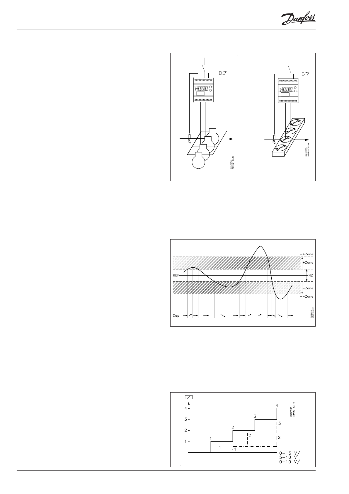
Capacity regulation
The cut-in capacity is controlled by signals from the connected
pressure transmitter and the set reference.
Outside the reference a neutral zone is set where the capacity will
neither be cut in nor out.
Outside the neutral zone (in the hatched areas named +zone and
-zone) the capacity will be cut in or out if the regulation registers a
change of pressure “away” from the neutral zone. Cutin and cutout
will take place with the set time delays.
If the pressure however “approaches” the neutral zone, the controller will make no changes of the cut-in capacity.
The size of the +zone and -zone is identical and defi ned to be
constantly 0.7 times the set value of the neutral zone.
If regulation takes place outside the hatched area (named ++zone
and --zone), changes of the cut-in capacity will occur somewhat
faster than if it were in the hatched area. The set time delays will
here be reduced by factor 0.3.
Cutin of steps can be defi ned for either sequential or cyclic operation.
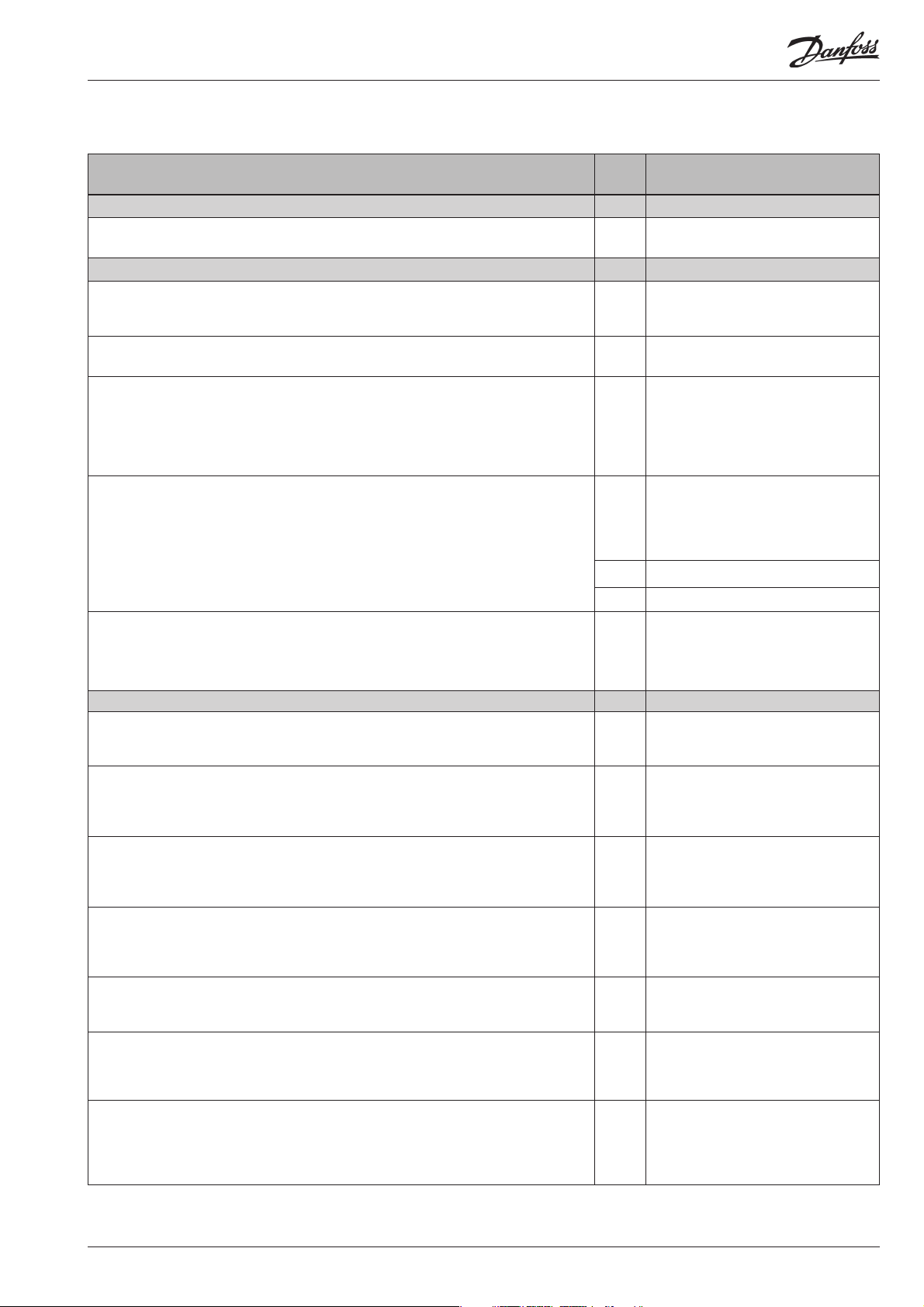
Relay module
The controller can also be used as a relay module where the relays
in the module will then be controlled by the received voltage
signal.
Depending on the defi nition of the signal and the number of
relays used, the relays will be “distributed” over the signal.
A hysteresis around the individual cutin and cutout points will
ensure that the relay will not cut in or out when it is not called for.
2 Manual RS.8A.G2.02 © Danfoss 10-2000 EKC 331
Page 3
Survey of functions
Function Para-
Normal display
Normally the signal from the pressure transmitter is shown. If the controller is used as
relay module, U
Pressure regulation Reference
Regulation reference
Regulation is based on the set value.
(Push both buttons simultaneously to set the menu.)
Neutral zone
There is a neutral zone around the reference. See also page 2.
Displacement of reference
The set reference may be displaced with a fi xed value when a signal is received at the
DI input. Regulation will then be based on the set reference plus the value set here.
The total reference can be seen when you push the lower of the two buttons. (Cf. also
Defi nition of DI input).
Reference limitation
The controller’s setting range for the reference can be narrowed down, so that you
cannot accidentally set a too high or too low value - that may result in damage to the
system. With these settings the reference can only be set between the two values.
Max. permissible reference value. r02 Max. set point
Min. permissible reference value. r03 Min. set point
Pressure unit
Here you can select whether the controller is to indicate the pressure in bar or psig.
(When psig is selected, the settings must also be in psig).
Alarm Alarm settings
The controller can give alarm in diff erent situations. When there is an alarm all the
light-emitting diodes (LED) will fl ash on the controller front panel, and the alarm relay
will cut in.
Upper deviation
Here you set when the alarm at high pressure is to enter into eff ect. The value is set as
an absolute value.
See also emergency procedure page 5.
Lower deviation
Here you set when the alarm at low pressure is to enter into eff ect. The value is set as
an absolute value.
See also emergency procedure page 5.
Alarm delay
If one of the two limit values is exceeded, a timer function will commence. The alarm
will not become active until the set time delay has been passed. The time delay is set
in seconds.
Give the top button a brief push to zeroset the alarm and to have the message shown
on the display.
will appear on the display.
in
meter
Parameter by operation via data
communication
Pressure
- Press. set point
r01 Neutral zone
r13 Pressure off set
r05 Unit
bar=0
psig=1
(In AKM only bar is used, whatever the
setting).
A10 Max. pressure
A11 Min. pressure
A03 Alarm delay
Reset alarm
The function zerosets all alarms when
set in pos. ON.
Alarm relay
Here you can read the status of the
alarm relay.
(ON indicates operation with alarm).
With data communication the importance of the individual alarms can be
defi ned. Setting is carried out in the
“Alarm destinations” menu. See also
page 8.
EKC 331 Manual RS.8A.G2.02 © Danfoss 10-2000 3
Page 4

Capacity Capacity
Running time
To prevent irregular operation, values have to be set for how the relays are to cut in
and out.
Min. ON time for relays. c01 Min.ON time
Time delay for cutin of relays. c05 Step delay inc.
Time delay for cutout of relays. c06 Step delay dec.
Min. time period between cutin of same relay. c07 Min recycle time
Coupling
Cutin and cutout can take place in three ways:
1. Sequential: First relay 1 cuts in, then relay 2, etc. Cutout takes place in the opposite
sequence.
2. Cyclic: An automatic operating time equalisation is arranged here, so that all steps
will have the same operating time. (The relay with the fewest number of operating
hours cuts in or out before the others).
3. Cyclic with unloader: The function can only be used when there are two compressors with one unloader each. The cyclic operation is performed on relays 1 and 3. The
unloaders are mounted on relays 2 and 4 (relays 1 and 2 belong to the fi rst compressor, relays 3 and 4 to the other). The above mentioned “Min. ON time for relays” is not
used by the two unloaders.
In connection with cutout, the two unloaders are cut out before the compressors are
cut out.
Unloaders’ cutin and cutout mode
(Only in connection with cutin/cutout mode 3. See above).
The relays for the two unloaders can be set to switch on when more capacity is
required (setting = 0), or they can switch off when more capacity is called for (setting
= 1).
Miscellaneous Miscellaneous
External signal
Here you set the signal to be connected to the controller.
0: No signal/regulation stopped (display will then show OFF)
1: 4-20 mA from pressure transmitter for compressor regulation
2: 4-20 mA from pressure transmitter for condenser regulation
3: Pressure transmitter type AKS 32R for compressor regulation
4: Pressure transmitter type AKS 32R for condenser regulation
5: 0-10 V from other regulation
6: 0-5 V from other regulation
7: 5-10 V from other regulation
Number of relays
Depending on the application, up to four relays may be used. This number must be
set in the controller. (The relays are always used in numerical sequence).
Pressure transmitter’s working range
Depending on the pressure, a pressure transmitter with a given working range is
used. This working range must be set in the controller (e.g.: -1 to 12 bar).
Min. value o20 Min. trans. press
Max. value o21 Max trans. press
Use of DI input
The digital input can be connected to a contact function, and the contact can now be
used for one of the following functions:
Setting / function:
0: DI input not used
1: Regulation reference displaced when contact is cut in
2: Regulation is started and stopped when the contact is cut in and out, respectively.
Operating hours
The operating hours for the four relays can be read in the following menus. The read
value is multiplied by 10 to obtain the number of hours. On reaching 999 hours the
counter stops and must now be reset to, say, 0. There will be no alarm or error message for counter overfl ow.
Value for relay number 1 o23 DO 1 run hour
Value for relay number 2 o24 DO 2 run hour
Value for relay number 3 o25 DO 3 run hour
Value for relay number 4 o26 DO 4 run hour
c08 Step mode
c09 Unloader
(switch on = 0)
(switch off = 1)
o10 Application mode
o19 Number of steps
o22 Di input control
(In the AKM display the hour number
has not been multiplied)
4 Manual RS.8A.G2.02 © Danfoss 10-2000 EKC 331
Page 5

Manual control
From this menu the relays can be cut in and out manually. OFF gives no override, but
a number between 1 and 4 will cut in a corresponding number of relays. Cutins and
cutouts always take place from relay number 1.
When there is manual operation, the display will show "- - x". Where x is 0 - 4.
Language
This setting is only required when data communication has been connected to the
controller.
Settings: 0=English, 3=Danish.
When the controller is operated via data communication, the texts in the right-hand
column will be shown in the selected language. When you change the setting to an
other language you must activate o04 before "the new language" can be visible from
the AKM program.
Frequency
Set the net frequency.
Address
If the controller is built into a network with data communication, it must have an
address, and the master gateway of the data communication must then know this
address.
These settings can only be madewhen a data communication modulehas been
mounted in the controller and the installation of the data communication cable has
been completed.
This installation is mentioned in a separate document “RC.8A.C”.
The address is set between 1 and 60 o03
o18 Manual control
o11
o12 Main freq
Only when “Manual control” has been
put in pos. ON will it be possible to
operate the individual relays.
DO relay 1
DO relay 2
DO relay 3
DO relay 4
Alarm relay set
When this function is used, the buttons on the controller cannot be used.
Language
(50=0, 60=1)
Following installation of a data communication module, the controller can
be operated on a par with the other
controllers in ADAP-KOOL® refrigeration controls.
The address is sent to the gateway when the menu is set in pos. ON
(The setting will automatically change back to Off after a few seconds.)
Access code
If the settings in the controller are to be protected by a numerical code, you can set a
numerical value between 0 and 100. If not, you can cancel the function with setting
OFF.
Operating status
The controller goes through some regulating situations where it is just waiting for
the next point of the regulation. To make these “why is nothing happening” situations
visible, you can see an operating status on the display. Push briefl y (1s) the upper
button. If there is a status code, it will be shown on the display. The individual status
codes have the following meanings:
S2: When the relay is operated, it must be activated for min. x minutes 2
S5: Renewed cutin of the same relay must not take place more often than every x
minutes
S8: The next relay must not cut in until x minutes have elapsed 8
S9: The next relay must not cut out until x minutes have elapsed 9
Emergency procedure
If the controller registers irregularities in the registered signals, it will start an emergency procedure:
o04
o05
EKC state
(0 = regulation)
5
For compressor regulation:
- If the signal from the pressure transmitter becomes smaller than expected, the controller will continue operating with the average
capacity that has been cut in during the past 60 minutes. This cut-in capacity will gradually decline as time passes.
- If the signal for the suction pressure becomes smaller than the set value of A11, the capacity will instantly be cut out.
For condenser regulation:
- If the signal from the pressure transmitter becomes smaller than expected, or if the condensing pressure becomes bigger than the set
value of A10, the entire capacity will in stantly be cut in.
EKC 331 Manual RS.8A.G2.02 © Danfoss 10-2000 5
Page 6

Operation
Menu survey
Display
The values will be shown with three digits, and with a setting you
can determine whether the pressure are to be shown in bar or in
psig.
Light-emitting diodes (LED) on front panel
There are four LED’s on the front panel which will light up when
the relays are operated.
All LED’s will fl ash if there is an error in the regulation. In this situation you can upload the error code on the display and cancel the
alarm by pushing the top button briefl y.
The controller can give the following messages:
E1
Error message
E2
A1
Alarm message
A2 Low pressure alarm
Errors in the controller
Regulation out of range or control signal is
defect.
High pressure alarm
The buttons
When you want to change a setting, the two buttons will give you
a higher or lower value depending on the button you are pushing. But before you change the value, you must have access to the
menu. You obtain this by pushing the upper button for a couple
of seconds - you will then enter the column with parameter codes.
Find the parameter code you want to change and push the two
buttons simultaneously. When you have changed the value, save
the new value by once more pushing the two buttons simultaneously.
Gives access to the menu
Gives access to changes
Saves a change
(or cutout an alarm)
Examples of operations
Set the regulation’s reference
1. Push the two buttons simultaneously
2. Push one of the buttons and select the new value
3. Push both buttons again to conclude the setting
Set one of the other menus
1. Push the upper button until a parameter is shown
2. Push one of the buttons and fi nd the parameter you want to
change
3. Push both buttons simultaneously until the parameter value is
shown
4. Push one of the buttons and select the new value
5. Push both buttons again to conclude the setting
Function
Normal display
Shows the signal from the pressure transmitter - bar
Reference
Set the regulation’s pressure reference - -1 bar 40 bar
Neutral zone r01 0,1 bar 5 bar
Max. limitation of pressure setting r02 -1 bar 40 bar
Min. limitation of pressure setting r03 -1 bar 40 bar
Select unit (0=bar / 1=psig) r05 0 1
Reference displacement by signal at DI input r13 -5 bar 5 bar
Alarm
Upper alarm limit (absolute value) A10 -1 bar 40 bar
Lower alarm limit (absolute value) A11 -1 bar 40 bar
Alarm's time delay A03 1 s 300 s
Capacity
Min. ON time for relays c01 0 s 900 s
Time delay for cutin of relays c05 5 s 900 s
Time delay for cutout of relays c06 5 s 900 s
Min. time period between cutins of same relay c07 0 s 900 s
Defi nition of regulation mode
1: Sequential
2: Cyclic
3: Cyclic with unloaders
If the regulation mode 3 has been selected, the relays for
the unloaders can be defi ned to:
0: Cut in when more capacity is required
1: Cut out when more capacity is required
Miscellaneous
Controllers address o03* 1 60
On/off switch (service-pin message) o04* - -
Access code o05 off (-1) 100
Defi ne input signal and application:
0: no signal / regulation stopped
1: 4-20 mA pressure transmitter - compressor reg.
2: 4-20 mA pressure transmitter - condenser reg.
3: AKS 32R pressure transmitter - compressor reg.
4: AKS 32R pressure transmitter - condenser reg.
5: 0 - 10 V relay module
6: 0 - 5 V relay module
7: 5 - 10 V relay module
Language (0=english, 3=danish). When you change this
setting you must also activate O04.
Set supply voltage frequency o12 50 Hz 60 Hz
Manual operation with “x” relays o18 0 4
Defi ne number of relay outputs o19 1 4
Pressure transmitter’s working range - min. value o20 -1 bar 0 bar
Pressure transmitter’s working range - max. value o21 1 bar 40 bar
Defi ne DI input:
0: not used
1: Contact displaces reference
2: Contact starts and stops regulation
Operating hours of relay 1 (value times 10) o23 0 h 999 h
Operating hours of relay 2 (value times 10) o24 0 h 999 h
Operating hours of relay 3 (value times 10) o25 0 h 999 h
Operating hours of relay 4 (value times 10) o26 0 h 999 h
*) This setting will only be possible if a data communication moduel has been
installed in the controller.
Param-
Min. Max.
eter
c08 1 3
c09 0 1
o10 0 7
011* 0 3
o22 0 2
Factory setting
If you need to return to the factory-set values, it can be done in this way:
- Cut out the supply voltage to the controller
- Keep both buttons depressed at the same time as you recon nect the supply voltage
6 Manual RS.8A.G2.02 © Danfoss 10-2000 EKC 331
Page 7

Data
Supply voltage 230 V a.c. +/-15% 50/60 Hz, 5 VA
Pressure transmitter*) with 4-20 mA or
Input signal
Relay output 4 pcs. SPST
Alarmrelay 1 pcs. SPST
Data communication
Ambient
temperature
Enclosure IP 20
Weight 300 g
Mounting DIN rail
Display LED, 3 digits
Terminals max. 2,5 mm
Approvals
*) Pressure transmitter
As pressure transmitter can be used AKS 3000 or AKS 33
(AKS 33 has a higher accuracy than AKS 3000).
It is also possible to use an AKS 32R. This pressure transmitter is
only supplied in large quantities as per arrangement with Danfoss.
Please refer to catalogue RK.0Y.G...
voltage signal (0 - 5 V, 0 - 10 V
or 5 - 10 V)
Digital input to external contact function
AC-1: 4 A (ohmic)
AC-15: 3 A (inductive)
AC-1: 4 A (ohmic)
AC-15: 1 A (inductive)
Possible to connect a data communication
module
During operation
During transport
2
multicore
EU Low voltage Directive and EMC demands re
CE-marking complied with.
LVD-tested acc. to EN 60730-1 and EN 607302-9
EMC-tested acc. to EN50081-1 and EN 50082-2
-10 - 55°C
-40 - 70°C
Ordering
Type Function Code No.
EKC 331 Capacity controller 084B7104
EKA 173
EKA 175
Data communication module
(accessories), (FTT 10 module)
Data communication module
(accessories), (RS 485 module)
084B7092
084B7093
Connections
Necessary connections
Terminals:
25-26 Supply voltage 230 V a.c.
3- 10 Relay connections no. 1, 2, 3 and 4
12-13 Alarm relay
There is connection between 12 and 13 in alarm situa tions
and when the controller is dead
Control signal (see also o10)
Either terminals:
14-16 Voltage signal from AKS 32R
or
17-18 Current signal from AKS 3000 or AKS 33
or
15-16 Voltage signal from an other regulation.
External contact function, if applicable
19-20 Contact function for displacement of reference or start/
stop of the regulation.
Data communication, if applicable
21-22 Mount only, if a data communication module has been
mounted.
It is important that the installation of the data communication cable be done correctly. Cf. separate literature No.
RC.8A.C...
Data communication
EKC 331 Manual RS.8A.G2.02 © Danfoss 10-2000 7
Page 8

Data communication
This page contains a description of a few of the possibilities you will have
when the controller is provided with data communi cation.
Example
Each controller is provided with
a plug-in module type EKA 173.
The controllers are then connected to a two-core cable.
Up to 60 controllers may be connected to one cable.
This cable is also connected to a
gateway type AKA 243.
This gateway will now control the
communication to and from the
controllers.
It will collect pressure values and
it will receive alarms. When there
is an alarm the alarm relay will be
activated for two minutes
If you want to know more about operation of controllers via PC,
you may order additional literature.
The gateway can now be connected to a modem.
When an alarm occurs from one of
the controllers, the gateway will
- via the modem - make a phone
call to the service company.
At the service company a modem,
gateway and PC with system
software type AKM have been
installed.
All the controllers’ functions can
now be operated from the various
menu displays.
The programme will for example
upload all the collected temperature values once a day.
Example of menu display
Measurements are shown at one
side and settings at the other.
You will also be able to see the
parameter names of the functions
on page 3 - 5.
With a simple change-over the
values can also be shown in a trend
diagram.
If you wish to check earlier pressure
measurements, you can see them in
the log collection.
Alarms
If the controller is extended with
data communication, it will be
possible to defi ne the importance
of the transmitted alarms.
The importance is defi ned with
the setting: 1, 2, 3 or 0. When the
alarm then arises at some time, it
will result in one of the following
activities:
1 = Alarm
The alarm message is sent off with
alarm status 1. This means that the
gateway that is the master in the
system will have its alarm relay
output activated for two minutes.
Later, when the alarm ceases, the
alarm text will be retransmitted,
but now with status value 0.
2 = Message
The alarm text is transmitted with
status value 2. Later, when the
“message” lapses, the alarm text is
retransmitted, but now with status
value 0.
3 = Alarm
As “1”, but the master gateway’s
relay output is not activated.
0 = Suppressed information
The alarm text is stopped at
the controller. It is transmitted
nowhere.
Danfoss can accept no responsibility for possible errors in catalogues, brochures and other printed material. Danfoss reserves the right to alter its products without notice. This also applies to products
already on order provided that such alternations can be made without subsequential changes being necessary in specifi cations already agreed.
All trademarks in this material are property of the respecitve companies. Danfoss and Danfoss logotype are trademarks of Danfoss A/S. All rights reserved.
8 Manual RS.8A.G2.02 © Danfoss 10-2000 EKC 331
RC-ET
 Loading...