

Page 1
User Guide
Controller to regulate
CO2 gas pressure
EKC 326A
ADAP-KOOL® Refrigeration control systems
Page 2
Introduction
Application
The controller can be used in systems with transcritical and subcritical cooling control systems where CO2 is used as a refrigerant.
The controller regulates the pressure in the gas cooler (condenser) so that the system achieves the optimal COP.
The controller covers the following:
• Transcritical CO2 refrigeration systems (booster, cascade, high
pressure)
• Transcritical CO2 heat pump systems
• Transcritical CO2 refrigeration systems with heat recovery
• Transcritical CO2 chiller systems
• Extra capacity in warm periods. An improvement in the system’s
cooling performance can be achieved by displacement of the
set point (“extra compressor")
Advantages
• Maximum COP
The controller guarantees the system’s maximum performance
by maintaining the optimal pressure in the gas cooler when
regulation takes place in the transcritical range.
• The controller will always optimise to a subcritical state.
• Regulating the receiver pressure based on the receiver pressure
reading
• Heat recovery with adjustable reference pressure, 0-10 V
• Optimum heat pump operation
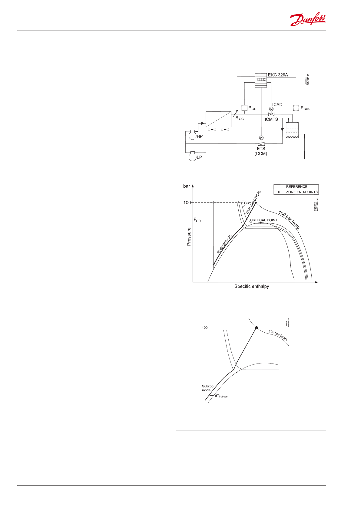
System
The pressure in the gas cooler is controlled by the valve. Regulation must have inputs from both a pressure transmitter PGC and
a temperature sensor SGC. Both must be tted in the outlet immediately after the gas cooler.
The valve is an ICMTS valve, which has been specially developed
for the pressure conditions that exist in a transcritical CO2 system.
The motor section of the valve is an ICAD actuator and is controlled by a 0-10 V signal from the controller.
If it is necessary to maintain a constant receiver pressure, a valve
(ETS, CCM or CCMT) and pressure transmitter (Prec) can be installed. The gas from the receiver bypasses to the inlet side of the
high pressure compressor.
Functions
Maximum COP control
The controller maintains optimum pressure in the transcritical
range based on a pressure and temperature reading.
The reference line is dened with a point at 100 bar. The desired
temperature can be set here.
Subcooling
d T subcooling can be used in the subcritical range.
Contents
Introduction ....................................................................................................... 2
Examples ............................................................................................................. 4
Survey of functions .......................................................................................... 6
Operation .......................................................................................................... 10
2 Manual RS8FM602 © Danfoss 02-2016 EKC 326A
Menu survey .....................................................................................................10
Connections ..................................................................................................... 11
Data ..................................................................................................................... 13
Ordering ............................................................................................................13
Appendix ........................................................................................................... 14
Page 3
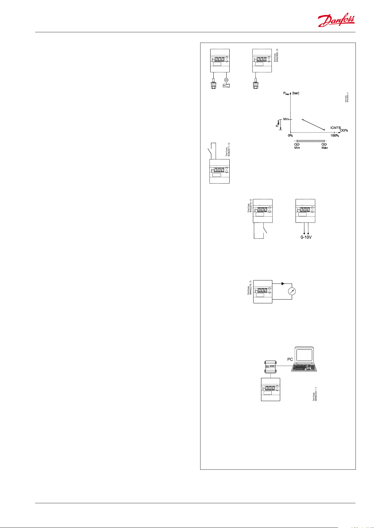
Receiver control
The receiver pressure can be controlled so that it is kept at a set
reference point. This control requires the installation of an ETS
valve a (CCM valve) and a pressure transmitter.
If only monitoring and not control is required, the valve should
not be installed. Install the pressure transmitter only.
Ensuring that the receiver pressure is not too low
A limit value can be set, and if the pressure falls below this value,
the ICMTS valve will be opened. The valve will then open gradually
through the associated P band. Open to the value "n32" ( Vhp OD
Max).
Protecting against high receiver pressure
A limit value can be set, and if the pressure rises beyond this value,
the ICMTS valve will be closed. The valve will then close gradually
through the associated P band.
Extra refrigeration capacity (“extra compressor”)
This function improves the system’s refrigeration capacity by
increasing the reference pressure in the gas cooler with a oset
value.
It is activated via a switch function.
Heat recovery or heat pump
This function will increase the gas pressure to a set value. This
value will be equivalent to a specic temperature.
The value can either be xed or can vary in accordance with an
input signal of 0-10 V as follows:
A signal of 1.5 V or above can activate the function and increase
the reference to Pgc HR Min.
If a variable reference is required, then a signal between 2-10 V
can be connected. The signal will increase the reference further.
This function works both in subcritical and transcritical ranges.
Output signal
The controller has a voltage output on 0-10 V. The signal is used to
control the ICMTS valve via the ICAD actuator.
Valves opening degree
The opening degree of both ICMTS and ETS valves (CCM valve)
can be narrowed if necessary.
PC-operation
The controller can be provided with data communication so that it
can be connected to other products in the range of ADAP-KOOL®
refrigeration controls. In this way operation, monitoring and data
collection can be performed from one PC – either on the spot or in
a service company.
Temperature reading
The temperature by the gas cooler must be measured using a Pt
1000 ohm sensor type AKS 21.
The sensor must be mounted immediately next to the gas
cooler outlet to produce a correct signal.
Pressure reading (bar)
The pressure by the gas cooler must be measured using a pressure
transmitter type AKS 2050.
The pressure transmitter must be mounted immediately next
to the gas cooler outlet to produce a correct signal.
Emergency cooling
The valve's average opening degree for the last six hours is
regularly saved. This opening degree is used if there is a need for
emergency cooling.
EKC 326A Manual RS8FM602 © Danfoss 02-2016 3
Page 4
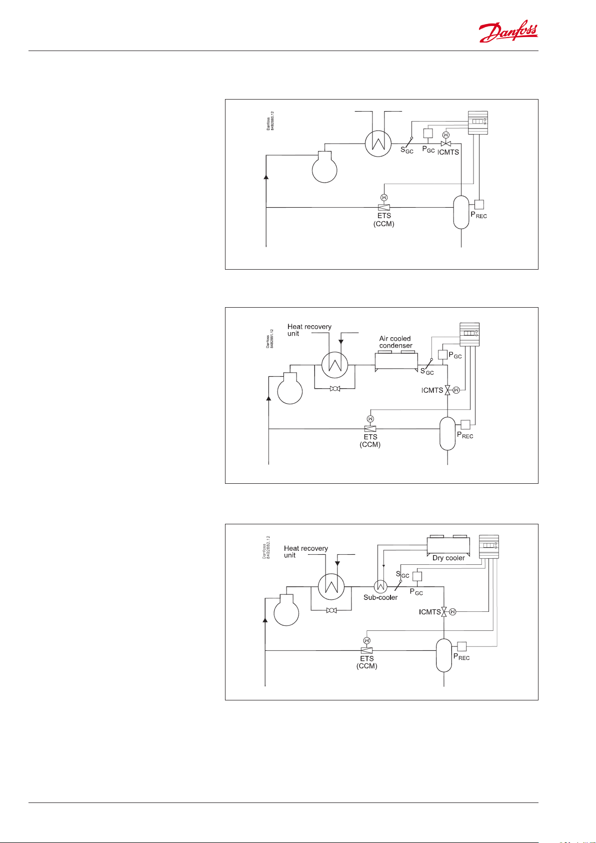
Examples
Simple heat recovery system
Partial heat recovery system
Heat recovery system
(or heat pump system)
4 Manual RS8FM602 © Danfoss 02-2016 EKC 326A
Page 5
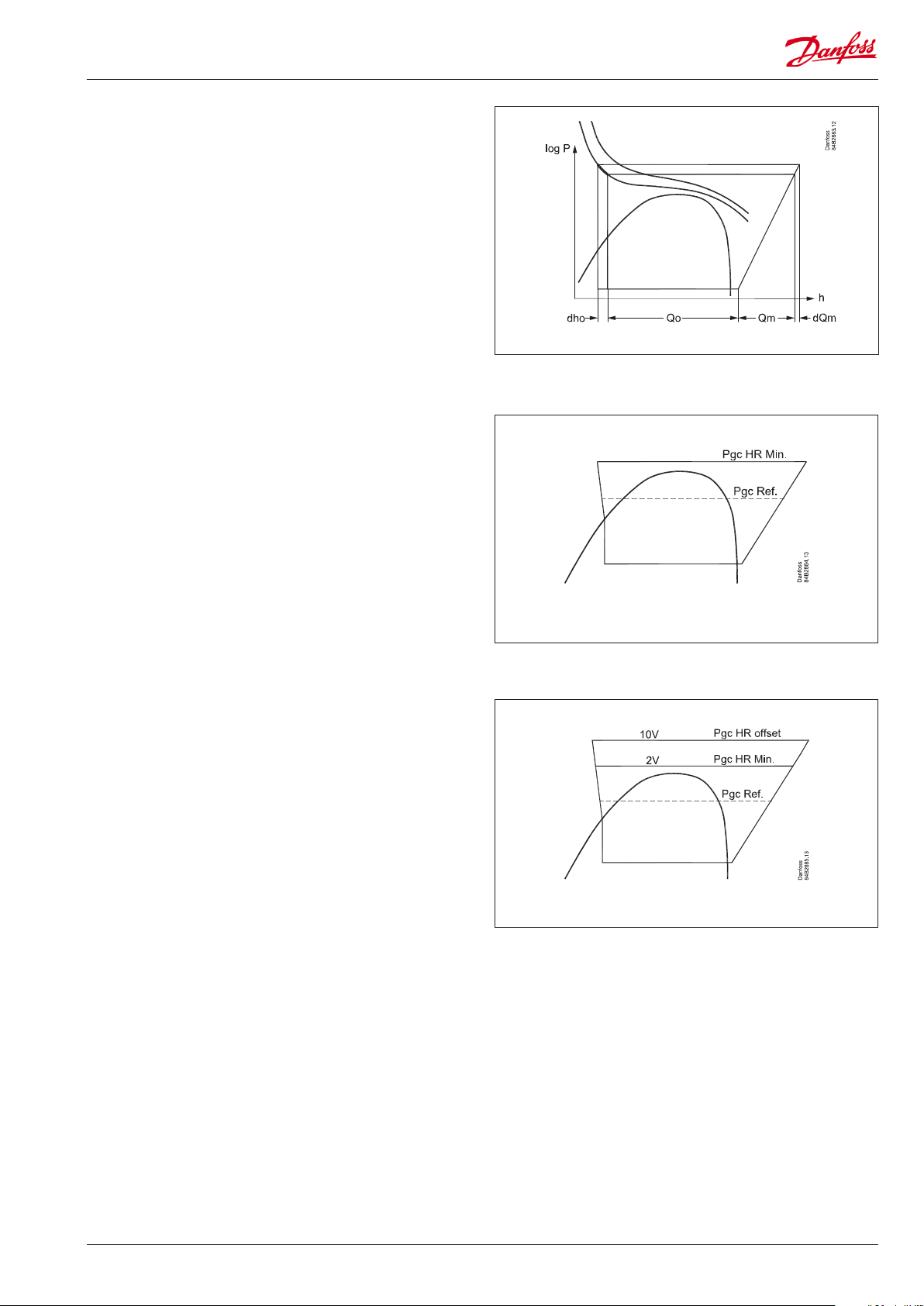
Extra refrigeration capacity (“extra compressor”)
This function improves the system’s refrigeration capacity by
increasing the reference pressure (Pgc Ref) in the gas cooler. The
cooling performance increases to Q0+dh0.
The function also increases the load on the compressor motor as
pressure increases. Power consumption increases to Qm+dQm.
Increasing pressure reference with heat recovery
The function will increase the gas pressure reference to the Pgc HR
Min. value when it receives a signal.
The function is activated by an on/o signal at the voltage input.
Increasing pressure reference with heat recovery, variable
reference
The function will increase the gas pressure reference to the value
where it receives a signal.
The function is activated by a voltage signal between 0-10 V.
• Between 0-2 V it is regulated normally
• At 2 V the reference changes to the setting “Pc HR Min”
• At 10 V the reference will increase further using the setting
“Pgc HR oset”
• Between 2-10 V the reference is variable.
EKC 326A Manual RS8FM602 © Danfoss 02-2016 5
Page 6

Survey of functions
Function Para-
meter
Normal display
The normal display shows the pressure in the gas cooler. The pressure is measured
using Pgc. The measurement can also be seen in menu U06.
The control reference can be viewed by pressing both buttons.
If a pressure transmitter is mounted to display the receiver pressure, the measurement can be brought up on the display by pressing the lower button. The measurement can also be seen in menu U07.
Gas pressure control Gas cooler control
Dening the reference line
Set the end point for the reference line in the transcritical range. Set the desired temperature value at 100 bar.
The reference
The reference is pre-programmed to follow the optimal COP from the pressure/enthalpy chart. See the illustration on page 2.
The current reference can be read o in menu U03.
Start/stop of regulation
This setting can be used to start and stop regulation.
Stopping regulation will always cause the valve will close at the value set in "n87" and
"n93".
The function in o02 requires that it has been dened.
Max. opening degree
The ICMTS-valve’s opening degree can be limited here.
Limitation takes place by limiting the voltage signal that is sent to the valve actuator.
The setting is expressed as a % of the total opening degree. The voltage signal of 0-10
V on the output will be limited correspondingly.
Minimum opening degree
The closing degree of the ICMTS valve can be limited here.
Limitation takes place by increasing the lower part of the voltage signal that is sent to
the valve actuator.
The setting is expressed as a percentage of the total opening degree. The output voltage signal of 0-10 V will be limited correspondingly.
The gas cooler’s max. pressure
This is where you dene the maximum pressure permitted in the gas cooler. If the
pressure reaches this value, the valve is open as set in "n32 OD max".
P-band to force open the valve from normal regulation
P-band under “n69, Pgc Max lim”, where the valve is forced open so that the valve is
fully open if the pressure reaches “n69, Pgc Max lim”.
The pressure is not critical, so opening of the valve will take place under controlled
conditions.
The gas cooler’s min. pressure
This is where you dene the minimum pressure permitted in the gas cooler.
Parameter by operation via
data communication
U06
Pgc bar
U07
Prec bar
n99 T100
U03 Pgc Ref
r12 Main Switch
n32 Vhp OD Max
n87 Vhp OD Min
n69 Pgc Max
n70 Pgc P-band
n81 Pgc Min
Subcooling is required to be regulated according to temperature
Set the desired subcooling in K.
P: Amplication factor Kp
If the Kp value is reduced the regulation becomes slower.
I: Integration time Tn
If the Tn value is increased the regulation becomes slower
Increasing refrigeration capacity
This function increases the gas pressure reference. Control moves from optimum
COP control to maximum refrigeration control. (The pressure increases, temperature
remains unchanged and the total heat content increases.)
Set the pressure increase value.
The function is activated by closing the switch function on terminals 1 and 2. (see
o02)
6 Manual RS8FM602 © Danfoss 02-2016 EKC 326A
n79 dT Subcool
n04 Kp Gascool
n05 Tn Gascool
n88 Pgc Cap Oset
Page 7

Minimum pressure reference during heat recovery
The function can only be used if heat recovery or heat pumps are also used in the system.
The function will increase the gas pressure to the set value when it receives a signal.
The function is activated by a voltage signal at the input to terminal 20. A voltage
over 1.5 V will activate the function. (Please install a support relay if there is any risk of
error signals, e.g. with long wires.)
If the function is only required for displacement, r68 should be set to 0.
(The gas pressure can be further increased using the r68 function.)
Displacement of the control reference during heat recovery
This function increases the reference to a value above the n89 setting, but no higher
than the set value.
Displacement occurs when an input voltage of above 2 V is received for terminal 20.
The new reference is: Setting in n89 + displacement.
The value of the displacement is determined by the voltage signal and the setting for
r68.
10 V gives maximum displacement, i.e. the set value. 2 V or below will give nothing.
Displacement is linear between 2 and 10 V.
Ramp for reference modication
This can be used to set the speed at which the reference must drop again following
heat recovery (number bar/min). The function is only active after heat recovery is
complete.
Receiver control Receiver pressure control
Receiver control
Whether control of the receiver pressure should take place is dened here.
On: ETS (CCM) control. Alarm active
O: No ETC (CCM) control. No alarm. Pressure control is active
Receiver reference
The reference for receiver control is set here.
n89 Pgc HR Min
r68 Pgc HR oset
r65 Pgc Ref Ramp
n90 Prec. Ctrl
n91 Prec Ref
Maximum opening degree
The ETS (CCM) valve’s opening degree can be limited here. The setting is expressed as
a percentage of the total opening degree.
Minimum opening degree
The closing degree of ETS (CCM) valves can be limited here. The setting is expressed
as a percentage of the total opening degree.
Min. pressure in the receiver
The function monitors the pressure in the receiver and will start to force open the
ICMTS-valve if the pressure falls below the preset value. The value must be at least 1
bar below the reference. The function is deactivated if n72 is set to 0.
P-band to force open the ICMTS-valve if the receiver pressure is too low
P-band under “n71, Prec Min” when the valve is forced open.
If the pressure falls to n71 minus n72, the ICMTS valve will open to the value in n32,
Vhp OD Max. An alarm is then transmitted.
The pressure is not critical, so opening of the valve will take place under controlled
conditions.
P: Amplication factor Kp
If the Kp value is reduced the regulation becomes slower.
I: Integration time Tn
If the Tn value is increased the regulation becomes slower
Actuator type
If receiver control takes place, the type of valve should be set:
0: ETS 12½, ETS 25, CCM 10, CCM 20
1: ETS 50, CCM 30
2: ETS 100, CCM 40
3: ETS 250
4: ETS 400
5: Other type. "n37" and "n38" should also be set when the setting = 5
("n37" and "n38" are automatically set for settings 0 to 4)
6: CCMT 2, 4, 8
ETS (CCM) setting
Number of steps open from 0-100%
Automatically set when "n03" is set to 0, 1, 2, 3, 4 or 6
ETS (CCM) setting
Speed of spindle travel (no. of steps per second)
Automatically set when "n03" is set to 0, 1, 2, 3, 4 or 6
n92 Vgbp OD Max
n93 Vgbp OD Min
n71 Prec Min
n72 Prec Min Pband
n60 Kp Receiver
n61 Tn Receiver
n03 Valve type
n37 Max. steps
n38 Steps / sec
EKC 326A Manual RS8FM602 © Danfoss 02-2016 7
Page 8

Max. pressure in the receiver
The function monitors the pressure in the receiver and will initiate the closing of the
ICMTS valve if the pressure exceeds the preset value. The value must be at least one
bar over the reference. The function is not activated when 'n59' is set to 0.
(If n70 is active and attempts to open the valve, n58 will not be active.)
P-band to force closing the ICMTS-valve if the receiver pressure is too high
P-band over “n58, Prec Max” when the valve is forced closed.
If the pressure becomes 'n58' plus 'n59', the ICMTS valve will be closed.
The closing of the valve will take place under controlled conditions.
Miscellaneous
Digital input signal - DI (terminal 1 and 2)
The controller has a digital input which can be used for one of the following functions:
0: The input is not used
1: External main switch (se also r12)
2: Increasing the pressure in the gas cooler (additional cooling capacity). (closed DI =
additional capacity)
Address
If the controller is built into a network with data communication, it must have an
address, and the master gateway (system unit) of the data communication must then
know this address.
These settings can only be made when a data communication module has been
mounted in the controller and the installation of the data communication cable has
been completed.
This installation is mentioned in a separate document “RC8AC”
The address is set between 0 and 119 (999) o03 -
The address is sent to the gateway when the menu is set in pos. ON
(The setting will automatically change back to O after a few seconds.)
n58 Prec Max
n59 PrecMaxPband
o02 DI Cong
o04 -
Following installation of a data communication module, the controller can
be operated on a par with the other
controllers in ADAP-KOOL® refrigeration controls.
Frequency
Set the net frequency.
Pressure transmitter denition for Pgc. Pressure transmitter lower limit o20 MinTransPgc
Pressure transmitter denition for Pgc. Pressure transmitter upper limit o21 MaxTransPgc
Pressure transmitter denition for Prec. Pressure transmitter lower limit o47 MinTransPrec
Pressure transmitter denition for Prec. Pressure transmitter upper limit o48 MaxTransPrec
Alarm settings Alarm settings
Pgc Min alarm limit
An alarm is issued if the value is exceeded
Permitted variation in relation to Pgc reference
An alarm is issued if the Pgc pressure falls below or exceeds the permitted variation,
but only once the delay time has expired. This is an 'A94 PgcRef alarm'.
Permitted variation in relation to the Prec reference
An alarm is issued if Prec pressure exceeds or falls below the permitted variation, but
only once the delay time has expired. This is an 'A95 PrecRef alarm'.
Delay time for 'A94 PgcRef alarm' A68 PgcAlDelay
Delay time for 'A95 PrecRef alarm' A69 PrecAlDelay
Service
A number of controller values can be printed for use in a service situation
Read input voltage at Ai-input u07 AI Volt
Read status of input DI (start/stop input)
Opening degree for ETS (CCM) valve u24 Vgbp OD %
Calculated reference for regulation (desired pressure in the gas cooler) U03 Pgc Ref
The output signal to the high pressure valve ICMTS converted into opening degree U04 Vhp OD %
The temperature in the gas cooler. Measured using temperature sensor Sgc. U05 Sgc temp.
The pressure in the gas cooler. Measured using pressure transmitter Pgc. U06 Pgc bar
The pressure in the receiver. Measured using pressure transmitter Prec, but only if it is
mounted.
o12 50 / 60 Hz
(50=0, 60=1)
A65 PgcMin AlLim
A66 PgcAl Limit
A67 PrecAl Limit
u10 DI
U07 Prec bar
8 Manual RS8FM602 © Danfoss 02-2016 EKC 326A
Page 9

Operating status
The controller’s operating status can be called forth by a brief (1s) activation of the
upper button. If a status code exists it will be shown. (Status codes have lower priority
than alarm codes. This means that status codes cannot be seen if there is an active
alarm code.
The individual status codes have the following meanings:
S10 (o): Regulation stopped by the internal start/ stop. 10
S20: Emergency cooling is activated because of defect sensor 20
S42: Heat recovery or heat pump control is active 42
S43: Higher capacity through displacement of the pressure reference 43
Alarms
E1: Fault in controller Controller fault
E15: Cut-out Sgc sensor Sgc o.c.
E16: Short circuited Sgc sensor Sgc S.C.
E20: Fault on the signal from Pgc Sgc input err
E39: Fault on the signal from Prec Prec input err
A43: Step motor error. Output or phase Step motor err
A45: Regulation stopped. Main switch r12 = o Standby mode
A82: The Pgc gas pressure measured is higher than the maximum limit for n69 PgcMax alarm
A83: The Pgc gas pressure measured is lower than the minimum limit for A65 PgcMin alarm
A84: The receiver pressure measured is lower than "n71" minus "n72" PrecMin alarm
A94: Pgc gas pressure measured is outside the permitted reference PgcRef alarm
A95: Prec receiver pressure measured outside the permitted reference PrecRef alarm
EKC State
(0 = regulation)
EKC 326A Manual RS8FM602 © Danfoss 02-2016 9
Page 10

Operation Menu survey
Display
The values will be shown with three digits.
Temperature are to be shown in °C and pressure in bar.
Light-emitting diodes (LED) on front panel
The four LED’s will ash, if there is an error in the regulation.
In this situation you can upload the error code on the display and
cancel the alarm by giving the uppermost button a brief push.
The controller can give the following messages:
E1
E15 Cut-out Sgc sensor
Error message
E16 Short circuited Sgc sensor
E20 Fault on the signal from Pgc
E39 Fault on the signal from Prec
A43
A45 Regulation stopped. Main switch r12 = o
A82
A83
Alarm message
A84
A94 Pgc alarm limit "A66" is exceeded
A95 Prec alarm limit "A67" is exceeded
Fault in controller
Step motor error. Output or phase
The Pgc gas pressure measured is higher than the
maximum limit for n69
The Pgc gas pressure measured is lower than Pgc
min (A65)
The receiver pressure measured is lower than "n71"
minus "n72"
The buttons
When you want to change a setting, the two buttons will give you
a higher or lower value depending on the button you are pushing. But before you change the value, you must have access to the
menu. You obtain this by pushing the upper button for a couple
of seconds - you will then enter the column with parameter codes.
Find the parameter code you want to change and push the two
buttons simultaneously. When you have changed the value, save
the new value by once more pushing the two buttons simultaneously.
Gives access to the menu
Gives access to changes
Saves a change
(or cutout an alarm)
Examples of operations
Set a menus
1. Push the upper button until a parameter is shown
2. Push one of the buttons and nd the parameter you want to
change
3. Push both buttons simultaneously until the parameter value is
shown
4. Push one of the buttons and select the new value
5. Push both buttons again to conclude the setting
Function
Normal display
Shows the current pressure after the gas cooler
Pushing both buttons briey will display the
reference
Pushing the bottom button briey will display
Prec.
Start / stop
Start / stop of regulation r12 OFF (0) On (1) On (1)
Ramp for reference after heat recovery r65 0.1 20 1
Displacement of the Pgc minimum reference
(n89) during heat recovery. (Displacement value
at 10 V)
Alarm Settings
Alarm limit for Pgc Min. A65 0 bar 200 bar 40
Permitted Pgc reference variation
0 = no alarm function (recommended)
Permitted Prec reference variation
0 = no alarm function (recommended)
Delay time for 'A94' Pgc reference alarm A68 5 min. 360 min 15
Delay time for 'A95' Prec reference alarm A69 5 min. 360 min 15
Regulating parameters
Actuator type for receiver control
0=ETS12,5/25 / CCM10/20,
1=ETS50 / CCM30, 2=ETS100 / CCM40,
3=ETS250, 4=ETS400,
5=User dened (set: n37 and n38)
6=CCMT2/4/8
P: Amplication factor Kp n04 0.5 20 2.0
I: Integration time Tn n05 10 s 600 s 75
Max. opening degree. of the valve n32 0 100 100
Number of steps from 0-100% opening degree
(x10) **
Number of steps per second n38 0 300 250
Max. permitted receiver pressure, Prec n58 10 bar 200 bar 60
P-belt beyond PrecMax for valve to close n59 0 bar 60 bar 0
P: Amplication factor Kp for receiver n60 0.5 20 5
I: Integration time Tn for receiver n61 10 600 75
The gas cooler’s max. pressure
This is where you set the maximum pressure permitted in the gas cooler. If the pressure reaches
this value, the valve is fully open.
P-band under n69, so the valve is fully open if
the pressure is n69.
Min. pressure in the receiver
This function is only used if the pressure transmitter Prec is mounted.
P-band to force open the valve if the receiver
pressure is too low
Subcooling is required to be regulated according to temperature
Set the desired subcooling in K.
The gas cooler’s min. pressure n81 7 200 bar 45
Min. permissible opening degree for ICMTS n87 0 100% 0
Extra capacity when the contact is closed.
(The Pgc reference is increased with this value)
Minimum permitted Pgc reference during heat
recovery (AI > 2 V). The value can be increased
further using the r68 function.
Do you require receiver pressure control: O=no,
On=yes
Prec. reference for receiver pressure control n91 7 bar 200 bar 35
Receiver pressure control. Maximum opening
degree for ETS
Receiver pressure control. Smallest opening
degree for ETS
Dene the reference curve point at 100 bar. n99 35°C 55°C 39
SW =2.0x
Para-
Min. Max.
meter
- bar
r68 0 bar 100 bar 0
A66 0 bar 50 bar 0
A67 0 bar 50 bar 0
n03 0 6 0
n37 0 500 262
n69 7 200 90
n70 0 60 5
n71 7 60 30
n72 0 60 3
n79 1 K 30 K 1
n88 0 bar 200 bar 0
n89 7 bar 200 bar 7
n90 O On On
n92 0% 100% 100
n93 0% 100% 0
Factory
setting
**) The display on the controller can show 3 digits only, but the setting value has 4 digits. Only the
3 most important will be shown. It means fx. 250 will give a setting of 2500.
10 Manual RS8FM602 © Danfoss 02-2016 EKC 326A
Page 11

Miscellaneous
Digital input signal - DI
0: The input is not used
1: External main switch
2: additional cooling capacity
Controller’s address o03* 0 240 -
ON/OFF switch (service-pin message) o04* - - -
Set supply voltage frequency o12
Pressure transmitter range Pgc - min. o20 -1 bar 5 bar -1
Pressure transmitter range Pgc - max. o21 6 bar 199 bar 159
Pressure transmitter range Prec - min. o47 -1 bar 5 bar -1
Pressure transmitter range Prec - max. o48 6 bar 199 bar 59
*) This setting will only be possible if a data communication module has been installed in the
controller.
o02 0 2 0
50Hz
60 Hz
(0)
(1)
0
Service
Signal on AI the input u07 V
Read status of input DI u10 on/o
Read ETS/CCM valves opening degree u24 %
Calculated reference for regulation (desired pressure in the gas cooler)
The output signal to the ICMTS valve converted
into opening degree
The temperature in the gas cooler. Measured
using temperature sensor Sgc.
The pressure in the gas cooler. Measured using
pressure transmitter Pgc.
The pressure in the receiver. Measured using
pressure transmitter Prec, but only if it is
mounted.
Factory setting
If you need to return to the factory-set values, it can be done in this way:
- Cut out the supply voltage to the controller
- Keep both buttons depressed at the same time as you recon nect the supply voltage
U03 bar
U04 %
U05 °C
U06 bar
U07 bar
Connections
Cable connection
060G1034
14 = black
15 = brown
16 = blue
Necessary connections
Terminals:
25-26 Supply voltage 24 V a.c.
18-19 Pt 1000 sensor at gas cooler outlet (Sgc)
14,15,16 Pressure transmitter AKS 2050, -1 to 159 bar
To register the correct pressure it must be mounted as
close as possible to the gas cooler.
5-6 Voltage output to control the ICMTS valve.
Important
PGC and Sgc must be mount
ed near the gas cooler outlet
to produce a correct signal.
-
0 V = valve closed
10 V = valve open
High pressure valve
Vhp
8 VA
Gas bypass valve
See also next page
Vgbp
AKS 11: Max. 100°C
AKS 21: Max. 180°C
Application dependent connections
Terminals:
1-2 DI-input to either:
External main switch (see o02 and r12)
OR
Contact function for increasing capacity (optimised COP
operation stopped). (see o02)
Open connection = optimised COP operation
Closed connection = extra capacity.
12-13 Alarm relay
There is connection between 12 and 13 in alarm situa tions
14,16,17 Optional. A pressure transmitter can be connected so
that the pressure in the receiver can be monitored. The
pressure transmitter must be an AKS 2050, -1 to 59 bar.
21-24 If receiver pressure is to be controlled, a CCM or ETS valve
should be connected.
18-20 Heat recovery. A voltage signal between 2 and 10 V will
increase the gas pressure reference.
3-4 Data communication
Mount only, if a data communication module has been
mounted.
It is important that the installation of the data communication cable be done correctly. Cf. separate literature No.
RC8AC...
EKC 326A Manual RS8FM602 © Danfoss 02-2016 11
Page 12

ETS (CCM) connection
If the distance between EKC 326A and the ETS (CCM/CCMT) valve
exceeds 5 m a lter must be mounted to obtain the correct valve
function. The lter must be placed close to EKC 326A.
L < 5 m
5 m < L < 50 m
Connection
Dimensions
DIN-rail mounting
Ordering
Type Description Ordering
AKA 211 Filter
4 x 10 mH
084B2238
12 Manual RS8FM602 © Danfoss 02-2016 EKC 326A
Page 13

Data
Supply voltage
Power consumption Controller 8 VA
Input signal
Alarm relay 1 pcs. SPST
Actuator
Data communication
Environments
Enclosure IP 20
Weight 300 g
Mounting DIN rail
Display LED, 3 digits
Terminals max. 2.5 mm2 multicore
Approvals
24 V a.c. +/-15% 50/60 Hz
(the supply voltage is galvanically separated
from the input and output signals)
Pressure transmitter Ratiometric, AKS 2050
Pressure transmitter Ratiometric, AKS 2050
Digital input from external contact function
Voltage signal
Sensor input 1 pcs. Pt 1000 ohm
ICAD mounted on
ICMTS
ETS / CCM or
CCMT 2-8
Possible to connect a data communication module type EKA 174
-10 to +55°C, during operations
-40 to +70°C, during transport
20 - 80% Rh, not condensed
No shock inuence / vibrations
EMC acc. EN 61000-6-3 and EN 61000-4-(2-6, 8, 11)
LVD acc. EN 60730-1 and EN 60730-2-9
0-10 V
Ri = 100 k ohm
Signal range = 2-10 V
250 V a.c.
AC-1: 4 A (ohmic)
AC-15: 3 A (inductive)
Voltage signal
0-10 mA
Step motor
I-max. = 100 mA
Ordering
Type Function Code no.
EKC 326A Gas pressure controller 084B7252
Data communication module
EKA 174
Temperature sensor Pt 1000 ohm: .............. Kindly refer to catalogue RK0YG
Pressure transmitter type AKS 2050 ........... Kindly refer to tech.broch RD5GJ
(accessories),
(Lon-RS 485 module) with
galvanic separation
084B7124
EKC 326A Manual RS8FM602 © Danfoss 02-2016 13
Page 14

Appendix
Guideline for setting automatic safety control
The following ratio between pressure and temperature can be used
to set the automatic safety control.
Safety functions
There are two safety functions for the receiver. They are only available for gas-cooled regulation.
A P-belt must be installed to be able to regulate the function, but
both are standard set to zero, which makes the function inactive.
Receiver pressure's max. limit
Set a max. receiver pressure. If the controller register receiver
pressure beyond the set value, the ICMTS valve will be closed.
The opening degree will be linear through the p-band so that the
ICMTS valve will be closed by pressing 'set max. receiver pressure'
plus 'set-p-band'.
If the valve's opening degree is set to a limited value and cannot
be fully closed, the set opening degree value will be at the pressure 'set max. receiver pressure' plus 'set p-band'.
As such, gas can still be sent through the valve.
Receiver pressure's min. limit:
A minimum receiver pressure limit can be set. If the controller
register receiver pressure below the set value, the ICMTS valve will
be opened. The opening degree will be linear through the p-band,
and the maximum permitted opening degree of the ICMTS will be
present by pressing 'set min. receiver pressure' minus 'set-p-band'.
If the setting of the valve's opening degree is limited and it cannot
be fully opened, the set opening degree value will be at the pressure 'set min. receiver pressure' minus 'set p-band'.
Regulation limitations of the receiver pressure
Note
The PI regulation of the receiver pressure must have space to
regulate without restrictions.
This means that there should be sucient space for the PI regulation to move around the reference, i.e. at least 2-3 bars – both over
and below the reference.
The value is very dependent on the tuning of the PI regulation
and the system dynamics.
An example may be a 40-bar plant in which the receiver's reference pressure is set to 35 bars. Here the system can interfere
with normal regulation because the high pressure limit is very
stringent.
14 Manual RS8FM602 © Danfoss 02-2016 EKC 326A
Page 15

Functions for regulation reference
EKC 326A Manual RS8FM602 © Danfoss 02-2016 15
Page 16

Valve function in alarm situations
Error Alarm message ICMTS action (Vhp) ETS action (Vgbp)
EKC supply interrupted none EKC AO remains 0 V – ICMT closes if ICMTS has
EKC Standby – Main
Switch OFF
Sgc interrupted E15 – Sgc o.c. ICMTS regulates with “Emergency cooling” No change – ETS control attempts to maintain
Sgc short circuited E16 – Sgc s.c. ICMTS regulates with “Emergency cooling” No change – ETS control attempts to maintain
Pgc transmitter error E20 – Pgc input err ICMTS regulates with “Emergency cooling” No change – ETS control attempts to maintain
Prec transmitter error E39 – Prec input err No change – ICMTS control continues ETS regulates with “Emergency cooling”
StepMotor error A43 – Step motor err No change – ICMTS control continues ETS closes to 'Vgbp OD Min' setting
Pgc Max limit exceeded A82 – PgcMax alarm No change – ICMTS control attempts to lower
Pgc Min limit exceeded A83 – PgcMin alarm No change – ICMTS control attempts to raise Pgc No change – ETS control attempts to maintain
Prec Min limit exceeded A84 – PrecMin alarm No change – ICMTS control attempts to maintain
PgcRef Alarm A94 – PgcRef alarm No change – ICMTS control attempts to maintain
PrecRef Alarm A95 – PrecRef alarm No change – ICMTS control attempts to maintain
EKC HW error E1 – Controller fault No change – ICMTS control continues No change – ETS control continues
A45 – Standby mode ICMTS closes ETS closes to 'Vgbp OD Min' setting
battery back-up
Pgc
Pgc
Pgc
Pgc
No change in opening degree
Prec
Prec
Prec
No change – ETS control attempts to maintain
Prec
Prec
No change – ETS control attempts to raise Prec
No change – ETS control attempts to raise Prec
No Change – ETS control attempts to raise Prec
"Emergency cooling"
The valve's average opening degree for the last six hours is
regularly saved. This opening degree is used if there is a need for
emergency cooling.
List of literature
Instructions RI8NG (extract from this manual).
Here you can see how controllers are mounted and
programmed.
Installation guide for extended operation RC8AC
Here you can see how a data communication
connection to ADAP-KOOL® Refrigeration control
systems can be established.
Installation considerations
Accidental damage, poor installation, or site conditions, can give
rise to malfunctions of the control system, and ultimately lead to a
plant breakdown.
Every possible safeguard is incorporated into our products to
prevent this. However, a wrong installation, for example, could still
present problems. Electronic controls are no substitute for normal,
good engineering practice.
Danfoss will not be responsible for any goods, or plant components, damaged as a result of the above defects. It is the installer's
responsibility to check the installation thoroughly, and to t the
necessary safety devices.
Danfoss can accept no responsibility for possible errors in catalogues, brochures and other printed material. Danfoss reserves the right to alter its products without notice. This also applies to products
already on order provided that such alternations can be made without subsequential changes being necessary in specications already agreed.
All trademarks in this material are property of the respecitve companies. Danfoss and Danfoss logotype are trademarks of Danfoss A/S. All rights reserved.
16 Manual RS8FM602 © Danfoss 02-2016 EKC 326A
ADAP-KOOL®
 Loading...