

Page 1
Identification
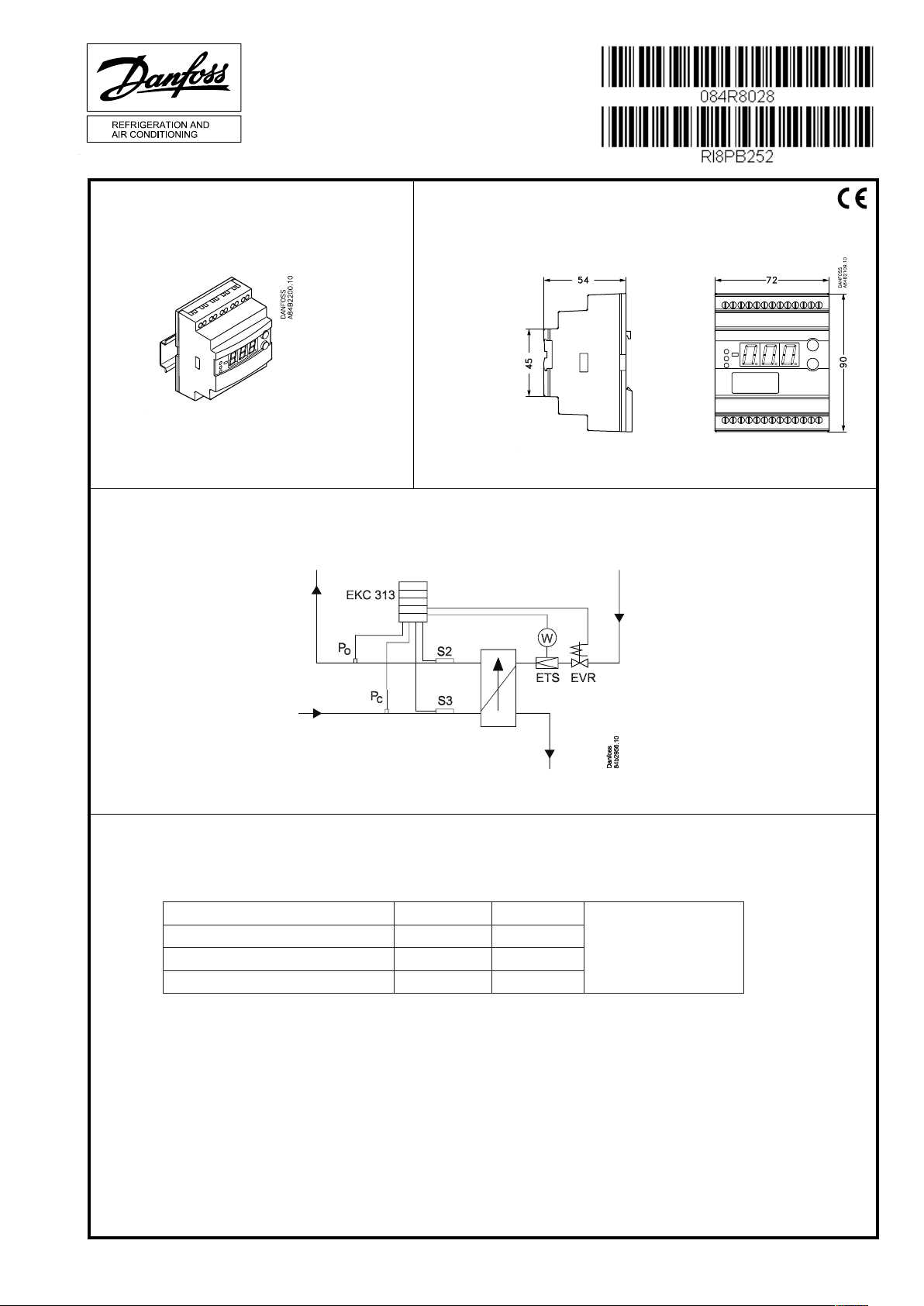
Principle
Instructions
EKC 313
Dimensions
084B7253
EKC 313
Additional information Manual RS8FZ---
Weitere Information Manual RS8FZ---
Renseignements supplémentaires: Manual RS8FZ---
Yderligere information: Manual RS8FZ---
RI8PB252 03-2011
www.danfoss.com
Page 2
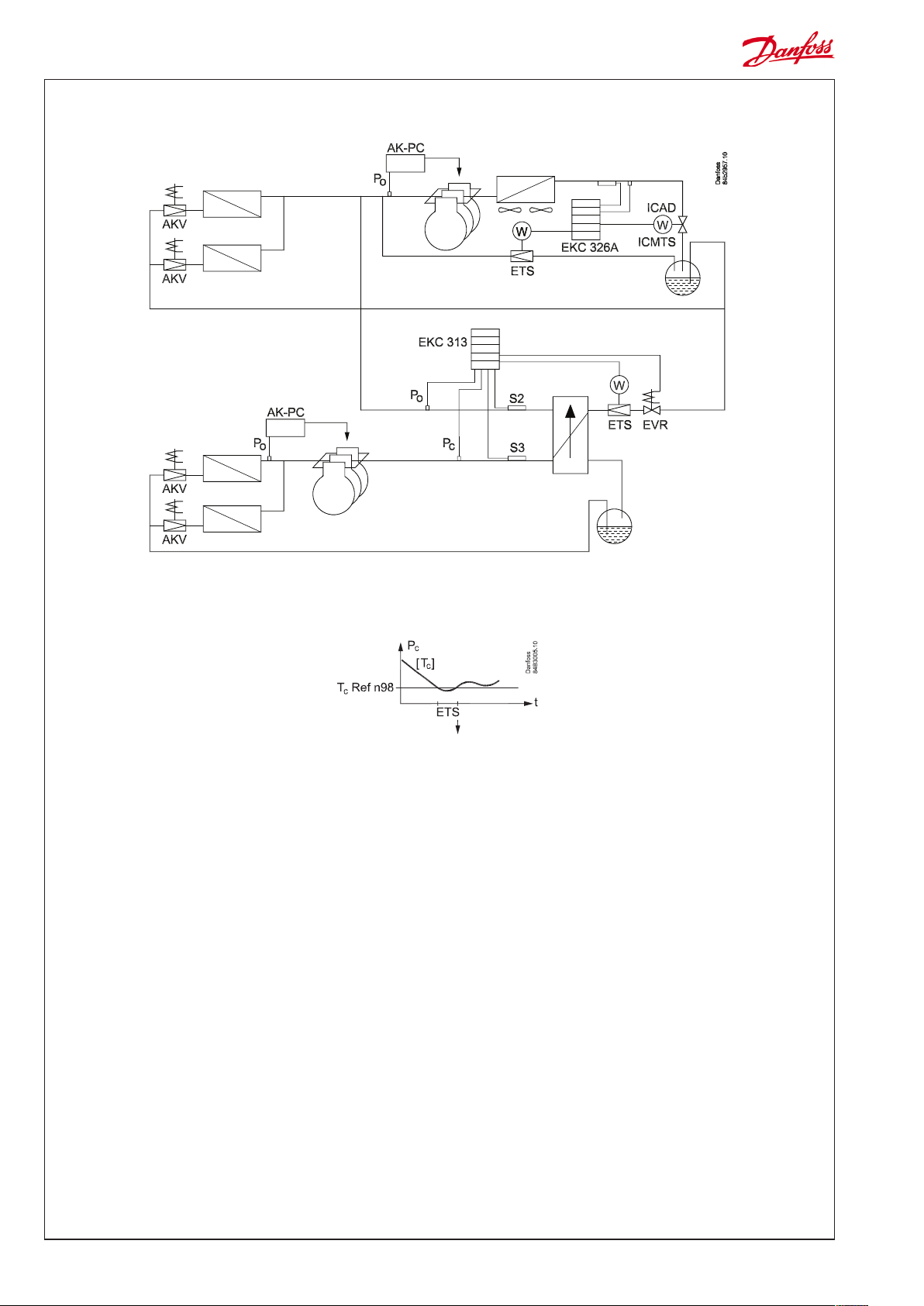
Example
Optimised superheat regulation with limit if the condensing pressure is low.
Optimised superheat regulation is used when the condensing
pressure is above the set value.
If the condensing pressure falls below the set value, the optimised
superheat regulation ceases and the ETS valve closes gradually
until the pressure rises above the value.
2 Instructions RI8PB252 © Danfoss 03/2011 EKC 313
Page 3

Connections
Cable connections
5,6 25,26
l
Earthing will damage the
controller
006G1034
14 = black
15 = brown
16 = Blue
Necessary connections
Terminals:
25-26 Supply voltage 24 V a.c.
18-19 Pt 1000 sensor at the heat exchanger discharge on
the cool side (S2)
18-20 Pt 1000 sensor at the heat exchanger input on
the warm side (S3)
14,15,16 Type AKS 2050* pressure transmitter, -1 to 59 bar.
Mounted at the heat exchanger's inlet on
the warm side (Pc)
14,16,17 Type AKS 32R* pressure transmitter, -1 to 12 bar.
Mounted at the heat exchanger discharge on
the cold side (P0)
8 VA
L > 5 m, see manual
AKS 11: Max. 100°C
AKS 21: Max. 180°C
Application dependent connections
Terminals:
1-2 DI input for external main switch (also see r12). If no
switch is mounted, the terminals should be short circuited.
12-13 Relay for controlling solenoid valve in liquid line or the
relay can be used as alarm relay (see o36).
Valve control: 12 and 13 are connected under normal
operating conditions and interrupted supply voltage.
Disconnects when regulation requires a low valve opening degree.
Alarm relay: 12 and 13 are connected under normal operating conditions and disconnected in case of alarm.
21,22,23,24 Connecting an ETS valve. (Terminals 21 through 24
should not be used when using an ICMTS valve instead
of an ETS valve. ICMTS valves should be controlled via the
0-10 V signal on terminals 5 and 6.)
5-6 Voltage output 0-10 V. Can be used for the valve's opening
degree signal or to control an ICMTS valve.
(For a special use with a solid state relay and AKV, the
output will pulse with 10 V on/off)
3-4 Data communication
Mount only, if a data communication module has been
mounted.
It is important that the installation of the data communication cable be done correctly. Cf. separate literature No.
RC8AC...
*) For explosive applications an intrinsically safe pressure transmitter can
be used. Connection is shown in manual page 12.
EKC 313 Instructions RI8PB252 © Danfoss 03/2011 3
Page 4

ENGLISH
Operation
Display
The values will be shown with three digits.
Temperature are shown in °C and pressure in bar.
Light-emitting diodes (LED) on front panel
All 4 light-emitting diodes will flash when there is an error in the
regulation.
In this situation you can upload the error code on the display and
cancel the alarm by giving the uppermost button a brief push.
The controller can give the following messages:
E1
E15
E16 Shortcircuited S2 sensor
Error message
E17 Cut-out S3 sensor
E18 Shortcircuited S3 sensor
E20 Fault on signal from Pc
E39 Fault on signal from P0
A11
A43 Step motor fault. Output or phase
Alarm message
A45 Regulation stopped. Main switch r12 = off
A92 No regulation parameters has been selected
The buttons
When you want to change a setting, the two buttons will give you
a higher or lower value depending on the button you are pushing. But before you change the value, you must have access to the
menu. You obtain this by pushing the upper button for a couple
of seconds - you will then enter the column with parameter codes.
Find the parameter code you want to change and push the two
buttons simultaneously. When you have changed the value, save
the new value by once more pushing the two buttons simultaneously.
Gives access to the menu
Gives access to changes
Saves a change
Examples of operations
Set of a menu
1. Push the upper button until a parameter is shown
2. Push one of the buttons and find the parameter you want to
change
3. Push both buttons simultaneously until the parameter value is
shown
4. Push one of the buttons and select the new value
5. Push both buttons again to conclude the setting
*) This setting will only be possible if a data communication module has been installed in the
controller.
**) The display on the controller can show 3 digits only, but the setting value has 4 digits. Only the
3 most important will be shown. It means fx. 250 will give a setting of 2500.
Fault in controller
Cut-out S2 sensor
No refrigerant has been selected
(or cutout an alarm)
Menu survey
Function
Normal display
Displays either the valve's current opening degree or the current superheat value.
(Can be set in o17)
Briefly pushing the bottom button will display one of the two readings.
Briefly pushing both buttons will display the superheat reference (u22).
Start / stop
Start / stop af regulation r12 OFF (0) On (1) On (1)
Regulating parameters
Select valve type:
0=ETS 12,5 & 25 / CCM10 & CCM20
1=ETS 50 / CCM30, 2=ETS 100 / CCM40
3=ETS 250, 4=ETS 400,
5=User defined (set : n37 and n38)
6=0-10 V's output must control ICAD actuator
7=0-10 V's output must on/off control a solid
state relay.
I: Integration time Tn n05 5 s 600 s 90
D: Differentiation time Td n06 0 s 60 s 0
Max. value of superheat reference n09 3 K 60 K 40
Min. value of superheat reference n10 3 K 40 K 10
MOP (max. = Off ) n11 0 bar 60 bar 60
Signal reliability during start-up. Time for safety.
Should only be changed by trained staff
Signal reliability during start-up – Opening
degree’s start value. Should only be changed by
trained staff.
Damping of amplification around reference
value
Changes should only be made by trained staff
Amplification factor for superheat
Changes should only be made by trained staff
Max. opening degree of valve n32 0% 100% 100
Number of steps from 0-100% opening degree
(x10) **
Number of steps per second n38 0 300 250
Max. Kp factor for PID-regulation n95 0 30 5
Calculation factor for superheat SH
Changes should only be made by trained staff
Filter constant for SH reference
Changes should only be made by trained staff
Lower limit value for the condensing pressure n98 -30°C 10°C -5
Miscellaneous
Controller’s address (0 = off) o03* 0 119 0
ON/OFF switch (service-pin message) o04* - - Set supply voltage frequency o12 50Hz (0) 60 Hz (1) 0
Select display view for the "normal display"
1: Opening degree of the valve
2: Superheat
Manual control of outputs:
0: Normal regulation
1: Overriding. Manual control permitted
Pressure transmitter selection
1: AKS 32R / AKS 2050
2: Pressure transmitter with 0-10 V
3: Pressure transmitter with 1-5 V
Working range for pressure transmitter Pc - min. o20 -1 bar 5 bar -1
Working range for pressure transmitter Pc - max. o21 6 bar 199 bar 59
Refrigerant setting for P0 circuit
1=R12. 2=R22. 3=R134a. 4=R502. 5=R717.
6=R13. 7=R13b1. 8=R23. 9=R500. 10=R503.
11=R114. 12=R142b. 13=User defined.
14=R32. 15=R227. 16=R401A. 17=R507.
18=R402A. 19=R404A. 20=R407C. 21=R407A.
22=R407B. 23=R410A. 24=R170. 25=R290.
26=R600. 27=R600a. 28=R744. 29=R1270.
30=R417A. 31=R422A. 32=R413A. 33=R422D.
34=R427A. 35=R438A
Relay application: 0=Alarm relay. 1=EVR valve i
liquid line
Forced control of the valves opening degree.
(Only if o18 is set to manual)
Para-
Min. Max.
meter
n03 0 7 0
n15 0 s 240 s 0
n17 0% 100% 0
n19 0 30 3
n20 0 30 5
n37
0 500 263
n96 10 100 50
n97 5 s 600 s 60
o17 1 2 1
o18 0 1 0
o10 1 3 1
o30 0 35 0
o36 0 1 0
o45 0 100% 0
SW =2.0x
Fac.setting
4 Instructions RI8PB252 © Danfoss 03/2011 EKC 313
Page 5

Working range for pressure transmitter P0 - min. o47 -1 bar 5 bar -1
Working range for pressure transmitter P0 - max. o48 6 bar 199 bar 12
Refrigerant for Pc circuit
Can olny be changed via AKM / service tool
Factory setting
If you need to return to the factory-set values, it can be done in this way:
- Cut out the supply voltage to the controller
- Keep both buttons depressed at the same time as you recon nect the supply voltage
---- 0 35 28
Service
Read status of input DI u10 on/off
Temperature at S3 sensor u12 °C
Temperature at S2 sensor u20 °C
Read actual superheat SH u21 K
Read actual superheat reference u22 K
Read ETS valves opening degree u24 %
Read pressure at pressure transmitter P0 u25 bar
Read P0 converted to temperature u26 °C
Read calculated SH closing value U19 K
Read Pc converted to temperature U20 °C
Read pressure at pressure transmitter Pc U21 bar
EKC 313 Instructions RI8PB252 © Danfoss 03/2011 5
Page 6

6 Instructions RI8PB252 © Danfoss 03/2011 EKC 313
The Product contains electrical components
And may not be disposed together with domestic waste.
Equipment must be separate collected with Electrical and Electronic waste. According to Local and currently valid legislation.
 Loading...