

Page 1
User Guide
Controller for cascade systems
with CO
2
EKC 313
ADAP-KOOL® Refrigeration control systems
Page 2
Introduction
Danfoss
Application
The controller can be used in systems with cascade regulating and
CO2 as refrigerant on the low temperature circuit.
It regulates the cooling of the heat exchanger to optimise superheat.
Advantages
• Dedicated cascade controller
System
The controller must receive a signal from two pressure transmitters and two temperature sensors. The pressure transmitters must
have a type AKS 32R or AKS 2050 ratiometric output signal, as
determined by the actual pressure conditions. The signal from the
pressure transmitters can be a voltage signal of either 0-10 V or
1-5 V.
Type AKS 11 temperature sensors can be used, but type AKS 21
must be used if the temperature exceeds 100°C.
Functions
Output signal
The controller has a voltage output on 0-10 V.
The signal can be used for:
• Indicating the valve's opening degree when using an ETS valve
• Controlling the valve when using an ICAD/ICMTS valve
Valves opening degree
The valve's opening degree can be limited.
Relay
The relay in the controller can be used for:
• Alarm relay
• Control of solenoid valve in liquid line
Start/stop
A switch can be connected for starting and stopping the regulation.
PC-operation
The controller can be provided with data communication so that it
can be connected to other products in the range of ADAP-KOOL®
refrigeration controls. In this way operation, monitoring and data
collection can be performed from one PC – either on the spot or in
a service company.
84B2959.10
Contents
Introduction ....................................................................................................... 2
Example ............................................................................................................... 3
Function overview ........................................................................................... 4
Operation ............................................................................................................ 8
2 User Guide RS8FZ402 © Danfoss 2015-07 EKC 313
Menu survey ....................................................................................................... 8
Connections ..................................................................................................... 10
Data ..................................................................................................................... 11
Ordering ............................................................................................................11
Page 3
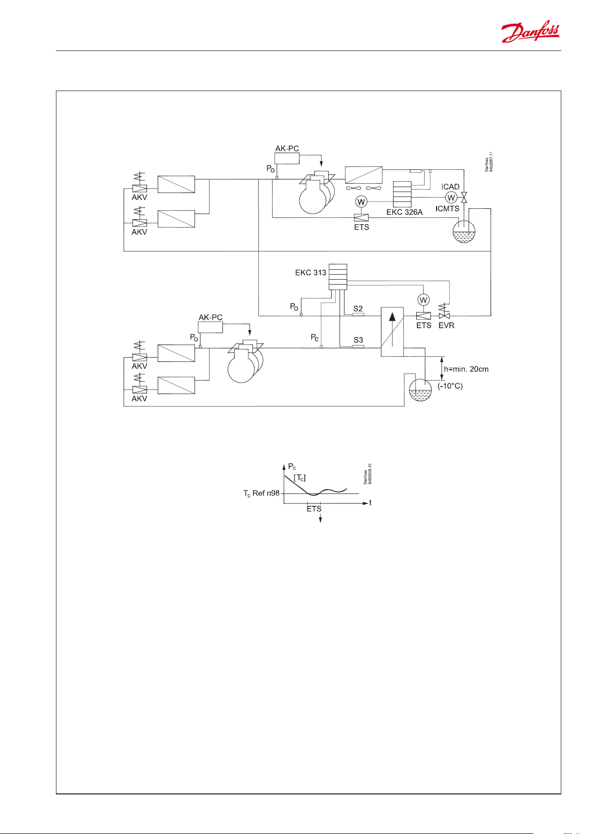
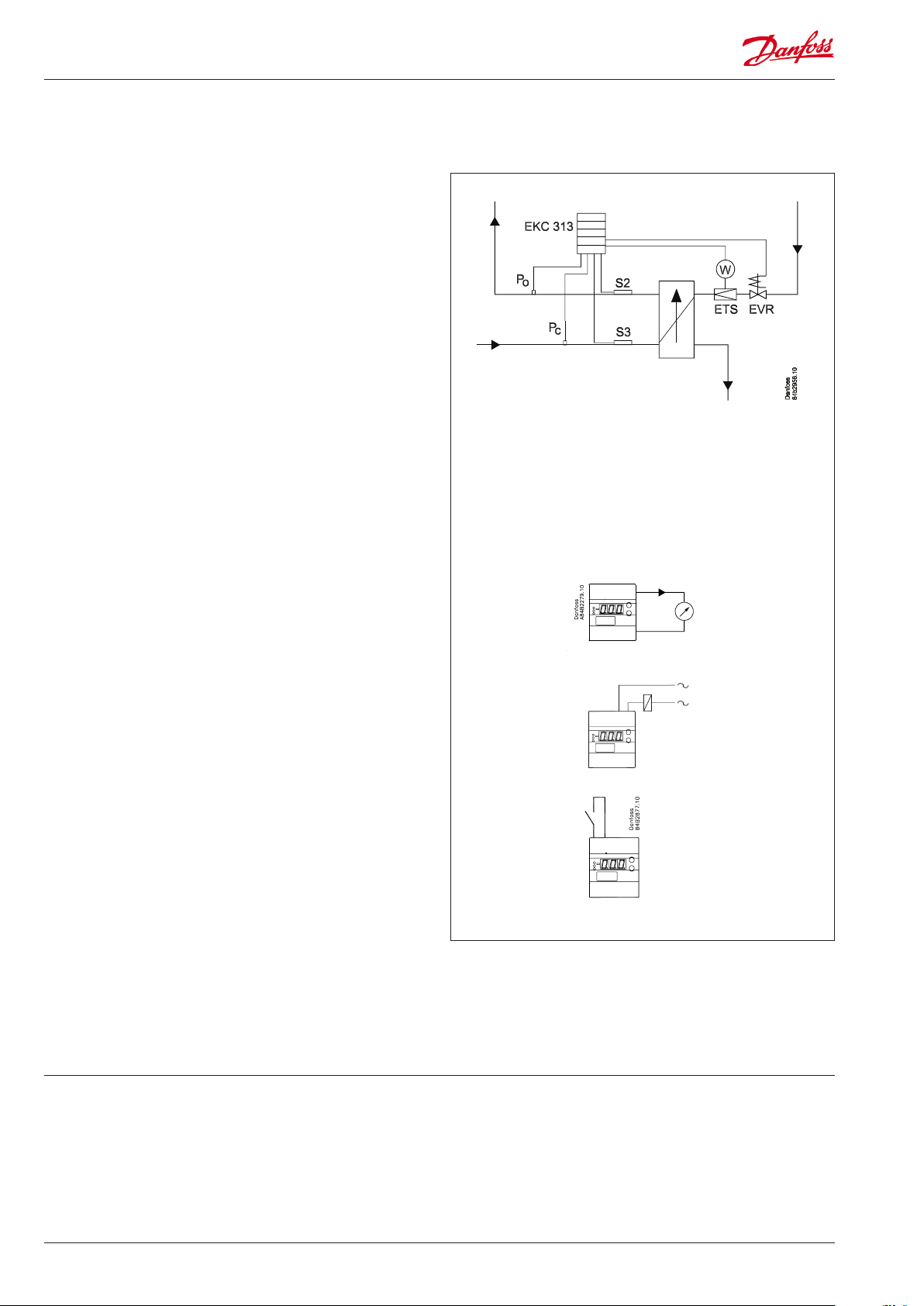
Example
Optimised superheat regulation with limit if the condensing pressure is low.
Optimised superheat regulation is used when the condensing
pressure is above the set value.
If the condensing pressure falls below the set value, the optimised superheat regulation ceases and the ETS valve closes
gradually until the pressure rises above the value.
EKC 313 User Guide RS8FZ402 © Danfoss 2015-07 3
Page 4
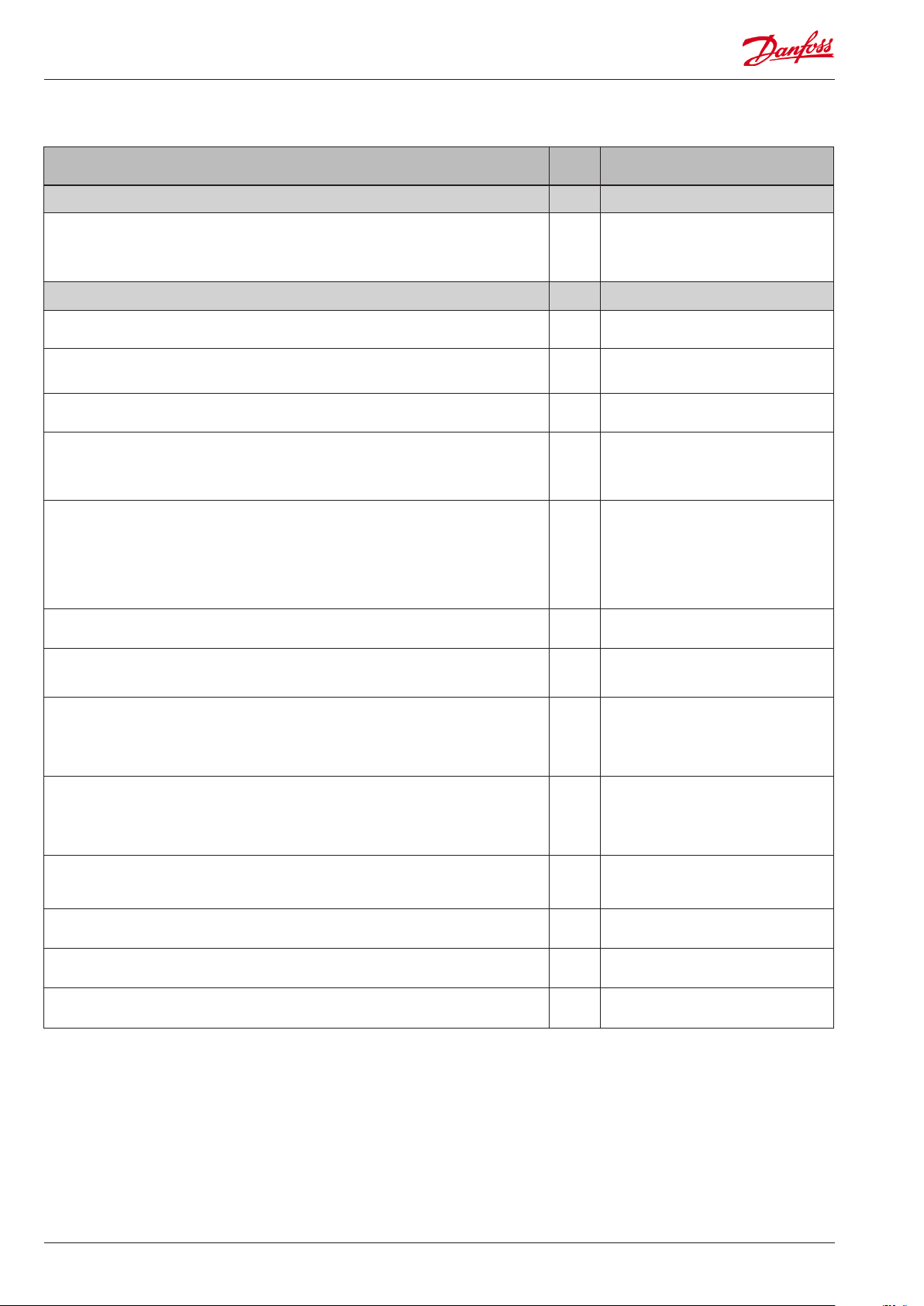
Function overview
Function Para-
meter
Normal display
Displays either the valve's actual opening degree or the actual superheat value.
(Desired value can be set in o17)
Briey pushing the bottom button will display one of the two readings.
Briey pushing both buttons will display the superheat reference (u22).
Control parameters Injection control
Start/stop of regulation
This setting can be used to start and stop regulation.
I: Integration time Tn
If the Tn value is increased the regulation becomes slower
Lower limit value for the condensing pressure.
If the pressure falls, the valve will start closing.
Max. opening degree
The valve's opening degree can be limited here.
The setting is expressed as a % of the total opening degree. The voltage signal of 0-10
V on the output will be limited correspondingly.
Amplication factor for the superheat
This setting determines the valve’s opening degree as a function of the change in
evaporating pressure. An increase of the evaporating pressure will result in a reduced
opening degree. When there is a drop-out on the low-pressure thermostat during
start-up the value must be raised a bit. If there is pendling during start-up the value
must be reduced a little.
The value should only be changed by specially trained sta.
Kp value for amplication factor for PID regulation n95 Kp Max
Parameter by operation via
data communication
u24 /
Valve OD %
u21
SH
r12 Main Switch
n05 Tn sec.
n98 Tc Ref
n32 OD% Max
n20 Kp T0
Kp value near reference value
Just around the reference this value will be used in stead of the "n95 value"
The value should only be changed by specially trained sta.
Signal safety during start-up
The control function uses the value as start value for the valve’s opening degree at
each thermostat cutin. By adaptive control the controller continuously calculates a
new value.
The value should only be changed by specially trained sta.
Start-up time for safety signal
If the controller does not obtain a reliable signal within this period of time the controller will in other ways try to establish a stable signal. (A too high value may result in
a ooded evaporator).
The value should only be changed by specially trained sta.
MOP
If no MOP function is required, select pos. O. (A value of max. (60) will correspond to
O)
Min. value for the superheat reference n10 SH Min
Max. value for the superheat reference n09 SH Max
D: Dierentiation time Td n06 Td sec
n19 Kp Min
n17 Start OD%
n15 StartUp time
n11 MOP (bar)
4 User Guide RS8FZ402 © Danfoss 2015-07 EKC 313
Page 5

Conguration Control cong
Refrigerant setting on evaporator side
Before refrigeration can be started, the refrigerant must be dened. You can select the
following refrigerants:
1=R12. 2=R22. 3=R134a. 4=R502. 5=R717. 6=R13. 7=R13b1. 8=R23. 9=R500.
10=R503. 11=R114. 12=R142b. 13=User dened. 14=R32. 15=R227. 16=R401A.
17=R507. 18=R402A. 19=R404A. 20=R407C. 21=R407A. 22=R407B. 23=R410A.
24=R170. 25=R290. 26=R600. 27=R600a. 28=R744. 29=R1270, 30= R417A.
31=R422A. 32=R413A. 33=R422D. 34=R427A. 35=R438A.
(Warning: Wrong selection of refrigerant may cause damage to the compressor).
Refrigerant setting on the condenser side
Factory-set to R744, but can be changed. A modication can only be made via AKM.
Actuator type
0: ETS 12½ and ETS 25 / CCM 10 and CCM 20
1: ETS 50 / CCM30
2: ETS 100 / CCM40
3: ETS 250
4: ETS 400
5: Other type. "n37" and "n38" should also be set when the setting = 5
("n37" and "n38" are automatically set for settings 0 to 4)
6: 0-10 V output must control an ICAD actuator
7: 0-10 V output must control a solid state relay, which, in turn, controls an AKV valve
(the signal will be an on/o signal [0 or 10 V])
NB! ETS 6 can not be used
ETS Setting
Number of steps from 0% to 100% open
Must only be set when "n03" is set to 5. Automatically set when "n03" is set to 0, 1, 2,
3 or 4
ETS setting
Spindle stroke speed (number of steps per second)
Must only be set when "n03" is set to 5. Automatically set when "n03" is set to 0, 1, 2,
3 or 4
Miscellaneous Miscellaneous
o30 P0 Rfg type
- Pc Rfg type
n03 Valve type
n37 Max. steps
n38 Steps / sec
Address
If the controller is built into a network with data communication, it must have an
address, and the master gateway of the data communication must then know this
address.
These settings can only be made when a data communication module has been
mounted in the controller and the installation of the data communication cable has
been completed.
This installation is mentioned in a separate document “RC8AC”
The address is set between 0 and 119 (999) o03 -
The address is sent to the gateway when the menu is set in pos. ON
(The setting will automatically change back to O after a few seconds.)
Pressure transmitter selection
1: Ratiometric with AKS 32R / AKS 2050
2: Voltage signal with 0-10 V
3: Voltage signal with 1-5 V
Pressure transmitter denition for Pc.
Pressure transmitter lower limit
Pressure transmitter denition for Pc.
Pressure transmitter upper limit
Pressure transmitter denition for P0.
Pressure transmitter lower limit
Pressure transmitter denition for P0.
Pressure transmitter upper limit
Frequency
Set the net frequency.
Denition of relay
The relay can be dened for the following applications:
0: Alarm relay
1: Control of EVR-valve in liquid line.
o04 -
o10 Trans. type
o20 MinTransPc
o21 MaxTransPc
o47 MinTransP0
o48 MaxTransP0
o12 50 / 60 Hz
o36 Alarm/Valve
Following installation of a data communication module, the controller can
be operated on a par with the other
controllers in ADAP-KOOL® refrigeration controls.
(50=0, 60=1)
EKC 313 User Guide RS8FZ402 © Danfoss 2015-07 5
Page 6

Display view
Normal display on the controller can be set to read one of the following readings:
1: Valve’s opening degree
2: Superheat
Only access via data communication For Danfoss only
o17 Display mode
Factor for calculating the superheat reference
SHref = (S3-P0) x SHfactor / 100
Filter constant (delay) for calculating the superheat reference n97 Ref Filter
Other refrigerant
If the refrigerant type cannot be selected directly via settings 1 through 33, it can
then be dened by the user. Select setting 13 and then set the refrigerant's three
constants via AKM.
Service Service
A number of controller values can be printed for use in a service situation
Read status of input DI (start/stop input) u10 DI status
Read the temperature at the S3 sensor u12 S3 Temp
Read the temperature at the S2 sensor u20 S2 Temp
Read the control’s actual superheat u21 SH
Read the control’s actual superheat reference u22 SH Ref
Read the ETS valve’s opening degree u24 Valve OD %
Reading the calculated closing value for superheating. U19 SH Close
Reading the condensation pressure calculated for temperature U20 Cond Temp Tc
Reading the condensation pressure (pressure at Pc) U21 Cond Press Pc
n96 SH factor
P0Rfg.Fac A1
P0Rfg.Fac A2
P0Rfg.Fac A3
PcRfg.Fac A1
PcRfg.Fac A2
PcRfg.Fac A3
Reading the evaporating pressure (pressure at P0) U25 Evap Press P0
Reading the evaporating pressure calculated for temperature U26 Evap Temp T0
Manual control of outputs
For service purposes the valve outputs can be forced
However only when regulation has been stopped.
0: No override
1: Override: If the relay is dened for solenoid valve use in o36, the solenoid valve will
open. The opening degree of the ETS or ICMTS valve can then be set via o45.
Manual control of the ETS valve
When ”o18” is activated (=1) the valve’s opening degree can be determined from this
menu.
Operating status
The controller’s operating status can be called forth by a brief (1s) activation of the
upper button. If a status code exists it will be shown. (Status codes have lower priority
than alarm codes. This means that status codes cannot be seen if there is an active
alarm code.
The individual status codes have the following meanings:
S10 (o): Regulation stopped by the internal start/ stop.
S24: Regulation is in start-up mode 24
S44: Delay time, or the time it takes for system stability to be reached. Appears if one
of the regulating sensors fails.
o18 Manual Ctrl
o45 Man Valve OD%
EKC State
(0 = regulation)
10
44
6 User Guide RS8FZ402 © Danfoss 2015-07 EKC 313
Page 7

Alarms
The controller can give the following alarms. The alarm priority for all alarms is factory-set to 1,
"High priority". The priority level can be modied, but only by altering the data communication
settings.
E1: Fault in controller Controller fault
E15: Cut-out S2 sensor S2 o.c.
E16: Short circuited S2 sensor S2 s.c.
E17: Cut-out S3 sensor S3 o.c.
E18: Short circuited S3 sensor S3 s.c.
E20: Fault on signal from Pc Pc input err
E39: Fault on signal from P0 P0 input err
A11: No refrigerant has been selected. o30 must be set No Rfg. Sel.
A43: Step motor fault. Output or phase Step motor err
A45: Regulation stopped. Main switch r12 = o Standby mode
Alarm destinations
EKC 313 User Guide RS8FZ402 © Danfoss 2015-07 7
Page 8

Operation
Display
The values will be shown with three digits.
Temperature are shown in °C and pressure in bar.
Light-emitting diodes (LED) on front panel
All 4 light-emitting diodes will ash when there is an error in the
regulation.
In this situation you can upload the error code on the display and
cancel the alarm by giving the uppermost button a brief push.
The controller can give the following messages:
E1
E15
E16 Short circuited S2 sensor
Error message
E17 Cut-out S3 sensor
E18
E20 Fault on signal from Pc
E39 Fault on signal from P0
A11
Alarm message
A43 Step motor fault. Output or phase
A45 Regulation stopped. Main switch r12 = o
The buttons
When you want to change a setting, the two buttons will give you
a higher or lower value depending on the button you are pushing. But before you change the value, you must have access to the
menu. You obtain this by pushing the upper button for a couple
of seconds - you will then enter the column with parameter codes.
Find the parameter code you want to change and push the two
buttons simultaneously. When you have changed the value, save
the new value by once more pushing the two buttons simultaneously.
Gives access to the menu
Gives access to changes
Saves a change
Examples of operations
Set of a menu
1. Push the upper button until a parameter is shown
2. Push one of the buttons and nd the parameter you want to
change
3. Push both buttons simultaneously until the parameter value is
shown
4. Push one of the buttons and select the new value
5. Push both buttons again to conclude the setting
*) This setting will only be possible if a data communication module has been installed in the
controller.
**) The display on the controller can show 3 digits only, but the setting value has 4 digits. Only the
3 most important will be shown. It means fx. 250 will give a setting of 2500.
Fault in controller
Cut-out S2 sensor
Short circuited S3 sensor
No refrigerant has been selected
(or cutout an alarm)
Menu survey
Function
Normal display
Displays either the valve's current opening degree or the current superheat value.
(Can be set in o17)
Briey pushing the bottom button will display one of the two readings.
Briey pushing both buttons will display the superheat reference (u22).
Start / stop
Start / stop af regulation r12 OFF (0) On (1) On (1)
Regulating parameters
Select valve type:
0=ETS 12,5 & 25 / CCM10 & CCM20
1=ETS 50 / CCM30, 2=ETS 100 / CCM40
3=ETS 250, 4=ETS 400,
5=User dened (set : n37 and n38)
6=0-10 V's output must control ICAD actuator
7=0-10 V's output must on/o control a solid
state relay.
I: Integration time Tn n05 5 s 600 s 90
D: Dierentiation time Td n06 0 s 60 s 0
Max. value of superheat reference n09 3 K 60 K 40
Min. value of superheat reference n10 3 K 40 K 10
MOP (max. = O ) n11 0 bar 60 bar 60
Signal reliability during start-up. Time for safety.
Should only be changed by trained sta
Signal reliability during start-up – Opening
degree’s start value. Should only be changed by
trained sta.
Kp amplication just around reference value
Changes should only be made by trained sta
Amplication factor for superheat. (KpT0)
Changes should only be made by trained sta
Max. opening degree of valve n32 0% 100% 100
Number of steps from 0-100% opening degree
(x10) **
Number of steps per second n38 0 300 250
Max. Kp factor for PID-regulation (Kp max) n95 0 30 5
Calculation factor for superheat SH
Changes should only be made by trained sta
Filter constant for SH reference
Changes should only be made by trained sta
Lower limit value for the condensing pressure n98 -30°C 10°C -5
Miscellaneous
Controller’s address (0 = o) o03* 0 119 0
ON/OFF switch (service-pin message) o04* - - Set supply voltage frequency o12 50Hz (0)60 Hz (1) 0
Select display view for the "normal display"
1: Opening degree of the valve
2: Superheat
Manual control of outputs:
0: Normal regulation
1: Overriding. Manual control permitted
Pressure transmitter selection
1: AKS 32R / AKS 2050
2: Pressure transmitter with 0-10 V
3: Pressure transmitter with 1-5 V
Working range for pressure transmitter Pc - min. o20 -1 bar 5 bar -1
Working range for pressure transmitter Pc - max. o21 6 bar 199 bar 59
Refrigerant setting for P0 circuit
1=R12. 2=R22. 3=R134a. 4=R502. 5=R717.
6=R13. 7=R13b1. 8=R23. 9=R500. 10=R503.
11=R114. 12=R142b. 13=User dened.
14=R32. 15=R227. 16=R401A. 17=R507.
18=R402A. 19=R404A. 20=R407C. 21=R407A.
22=R407B. 23=R410A. 24=R170. 25=R290.
26=R600. 27=R600a. 28=R744. 29=R1270.
30=R417A. 31=R422A. 32=R413A. 33=R422D.
34=R427A. 35=R438A
Relay application: 0=Alarm relay. 1=EVR valve i
liquid line
Forced control of the valves opening degree.
(Only if o18 is set to manual)
Working range for pressure transmitter P0 - min. o47 -1 bar 5 bar -1
Para-
Min. Max.
meter
n03 0 7 0
n15 0 s 240 s 0
n17 0% 100% 0
n19
0 30 3
n20 0 30 5
n37 0 500 263
n96 10 100 50
n97 5 s 600 s 60
o17 1 2 1
o18 0 1 0
o10 1 3 1
o30 0 35 0
o36 0 1 0
o45 0 100% 0
SW =2.0x
Fac.setting
8 User Guide RS8FZ402 © Danfoss 2015-07 EKC 313
Page 9

Working range for pressure transmitter P0 - max. o48 6 bar 199 bar 12
Refrigerant for Pc circuit
Can olny be changed via AKM / service tool
Service
Read status of input DI u10 on/o
Temperature at S3 sensor u12 °C
Temperature at S2 sensor u20 °C
Read actual superheat SH u21 K
Read actual superheat reference u22 K
Read ETS valves opening degree u24 %
Read pressure at pressure transmitter P0 u25 bar
Read P0 converted to temperature u26 °C
Read calculated SH closing value U19 K
Read Pc converted to temperature U20 °C
Read pressure at pressure transmitter Pc U21 bar
---- 0 35 28
Factory setting
If you need to return to the factory-set values, it can be done in this way:
- Cut out the supply voltage to the controller
- Keep both buttons depressed at the same time as you recon nect the supply voltage
EKC 313 User Guide RS8FZ402 © Danfoss 2015-07 9
Page 10

Connections
At opening degree: 10 V = 100% open valve
At signal to ICAD/ICMTS: 10 V = Open valve
5,6 25,26
l
Earthing will damage the
controller
Cable connection
060G1034
14 = black
15 = brown
16 = blue
Necessary connections
Terminals:
25-26 Supply voltage 24 V a.c.
18-19 Pt 1000 sensor at the heat exchanger discharge on
the cool side (S2)
18-20 Pt 1000 sensor at the heat exchanger input on
the warm side (S3)
14,15,16 Type AKS 2050* pressure transmitter, -1 to 59 bar.
Mounted at the heat exchanger's inlet on
the warm side (Pc)
14,16,17 Type AKS 32R* pressure transmitter, -1 to 12 bar.
Mounted at the heat exchanger discharge on
the cold side (P0)
8 VA
L > 5 m, see page 12
AKS 11: Max. 100°C
AKS 21: Max. 180°C
Application dependent connections
Terminals:
1-2 DI input for external main switch (also see r12). If no
switch is mounted, the terminals should be short circuited.
12-13 Relay for controlling solenoid valve in liquid line or the
relay can be used as alarm relay (see o36).
Valve control: 12 and 13 are connected under normal
operating conditions and interrupted supply voltage.
Disconnects when regulation requires a low valve opening degree.
Alarm relay: 12 and 13 are connected in case of alarm.
21,22,23,24 Connecting an ETS valve. (Terminals 21 through 24
should not be used when using an ICMTS valve instead
of an ETS valve. ICMTS valves should be controlled via the
0-10 V signal on terminals 5 and 6.)
5-6 Voltage output 0-10 V. Can be used for the valve's opening
degree signal or to control an ICMTS valve.
(For a special use with a solid state relay and AKV, the
output will pulse with 10 V on/o)
3-4 Data communication
Mount only, if a data communication module has been
mounted.
It is important that the installation of the data communication cable be done correctly. Cf. separate literature No.
RC8AC...
*) For explosive applications an intrinsically safe pressure transmitter can
be used. Connection is shown on page 12.
10 User Guide RS8FZ402 © Danfoss 2015-07 EKC 313
Page 11

Data
Supply voltage 24 V a.c. +/-15% 50/60 Hz
Power consumption Controller 8 VA
Ratiometric, AKS 32R
2 Pressure transmitter
Input signal
Digital input from external contact function
Sensor input 2 pcs. Pt 1000 ohm
Alarm relay / solenoid
valve relay
Actuator
Output signal
Data communication
Environments
Enclosure IP 20
Weight 300 g
Mounting DIN rail
Display LED, 3 digits
Terminals max. 2.5 mm2 multicore
Approvals
NB
EKC 313 does not support valve type ETS 6.
1 pcs. SPST
ETS /CCM / CCMT Step motor
ICAD mounted on
ICMTS
Voltage signal 0-10 V to either ICAD-control or to
signal for valves opening degree
Possible to connect a data communication mod-
ule type EKA 174
-10 to +55°C, during operations
-40 to +70°C, during transport
20 - 80% Rh, not condensed
No shock inuence / vibrations
EMC acc. EN 61000-6-3 and EN 61000-4-(2-6, 8,11)
LVD acc. EN 60730-1 and EN 60730-2-9
Ratiometric, AKS 2050
or 0-10 V / 1-5V
AC-1: 4 A (ohmic)
AC-15: 3 A (inductive)
Voltage signal 0-10 V
Ordering
Type Function Code no.
EKC 313 Cascade controller 084B7253
EKA 174
Temperature sensor Pt 1000 ohm and pressure transmitter:
Kindly refer to catalogue RK0YG
Data communication module
(accessories), (RS 485 module)
with galvanic separation
084B7124
EKC 313 User Guide RS8FZ402 © Danfoss 2015-07 11
Page 12

ETS connection
If the distance between EKC 313 and the ETS valve exceeds 5 m a
lter must be mounted to obtain the correct valve function.
L < 5 m
5 m < L < 50 m
Connection
The lter must be installed close to EKC 313
Dimensions
DIN-rail mounting
EX
Explosive application
Here the controller can receive a voltage signal of either 0-10 V or
1-5 V.
If the pressure transmitter supplies a current signal, a resistance of
250 ohm must be installed over the terminals.
The supply must be taken from the zener barrier.
Ordering
Type Description Code no.
AKA 211 Filter
4 x 10 mH
084B2238
List of literature
Accidental damage, poor installation, or site conditions, can give
rise to malfunctions of the control system, and ultimately lead to a
Installation considerations
Instructions RI8PB (extract from this manual).
Here you can see how controllers are mounted and
programmed.
plant breakdown.
Every possible safeguard is incorporated into our products to
prevent this. However, a wrong installation, for example, could still
present problems. Electronic controls are no substitute for normal,
Installation guide for extended operation RC8AC
Here you can see how a data communication
connection to ADAP-KOOL® Refrigeration control
systems can be established.
good engineering practice.
Danfoss will not be responsible for any goods, or plant components, damaged as a result of the above defects. It is the installer's
responsibility to check the installation thoroughly, and to t the
necessary safety devices.
Danfoss can accept no responsibility for possible errors in catalogues, brochures and other printed material. Danfoss reserves the right to alter its products without notice. This also applies to products
already on order provided that such alternations can be made without subsequential changes being necessary in specications already agreed.
All trademarks in this material are property of the respecitve companies. Danfoss and Danfoss logotype are trademarks of Danfoss A/S. All rights reserved.
12 User Guide RS8FZ402 © Danfoss 2015-07 EKC 313
ADAP-KOOL®
 Loading...