

Page 1
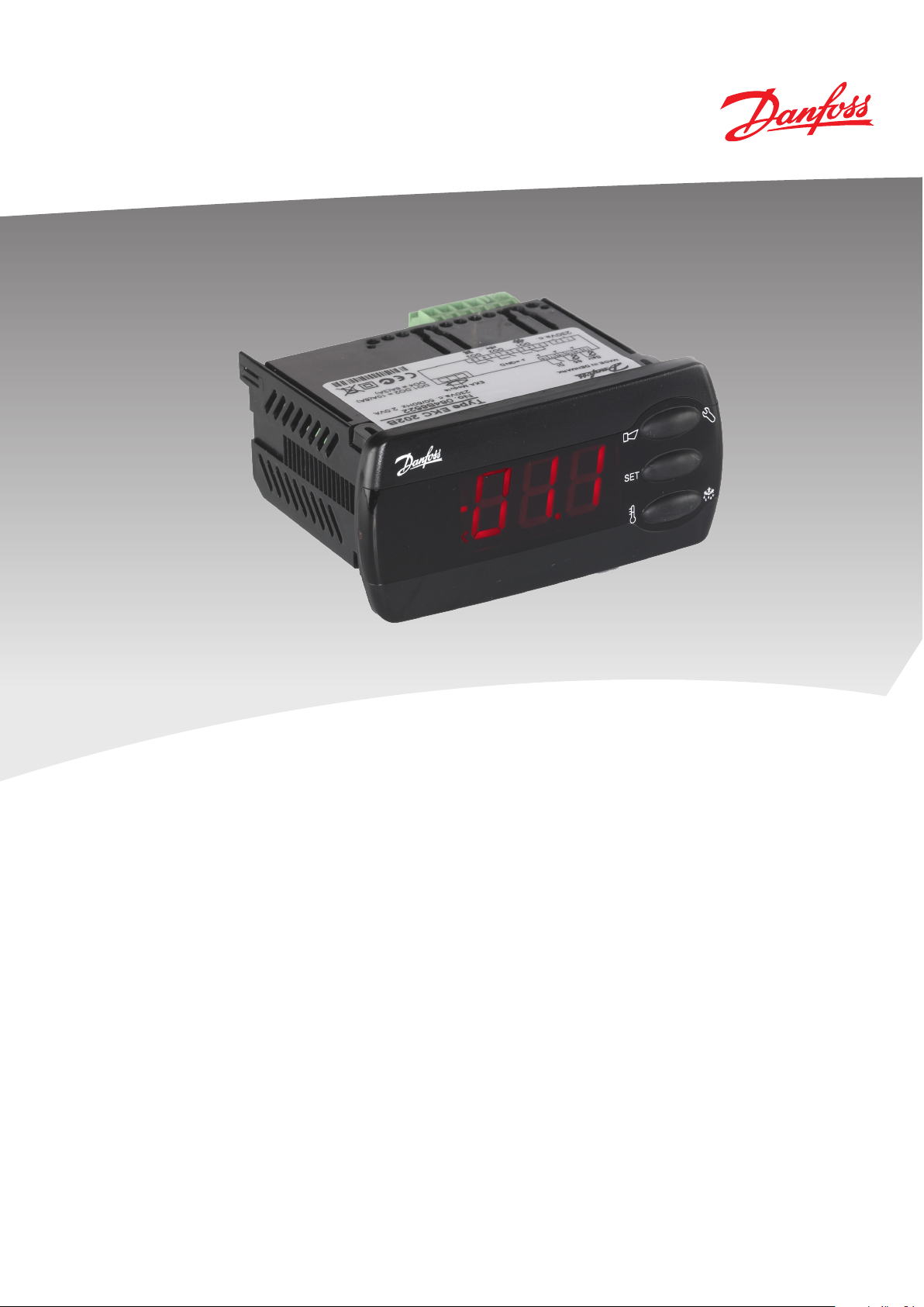
Controller for temperature control
- EKC 202D
Manual
Page 2
2 Manual RS8EE202 © Danfoss 08-2010 EKC 202D
Introduction
Application
• The controller is used for temperature control refrigeration
appliances in supermarkets.
• With many predened applications one unit will oer you
several options. Flexibility has been planned both for new
installations and for service in the refrigeration trade.
Principle
The controller contains a temperature control where the signal
can be received from one or two temperature sensors.
The thermostat sensors are either placed in the cold air ow after
the evaporator, in the warm air ow just before the evaporator,
or both. A setting will determine how great an inuence the two
signals are to have on the control.
A measurement of the defrost temperature can be obtained
directly through the use of an S5 sensor or indirectly through
the use of the S4 measurement. Four relays will cut the required
functions in and out – the application determines which.
The options are the following:
• Refrigeration (compressor or relay)
• Fan
• Defrost
• Rail heat
• Alarm
• Light
The dierent applications are described on page 6.
Advantages
• Several applications in the same unit
• The controller has integrated refrigeration-technical functions,
so that it can replace a whole collection of thermostats and
timers
• Buttons and seal imbedded in the front
• Easy to remount data communication
• Two temperature references
• Digital inputs for various functions
• Clock function with super cap backup
Contents
Introduction ....................................................................................................... 2
Operation ............................................................................................................ 3
Applications ....................................................................................................... 6
Survey of functions .......................................................................................... 7
Operation ..........................................................................................................16
Menu survey .....................................................................................................17
Override ............................................................................................................. 19
Ordering ............................................................................................................19
Connections .....................................................................................................20
Data .....................................................................................................................21
Page 3
EKC 202D Manual RS8EE202 © Danfoss 08-2010 3
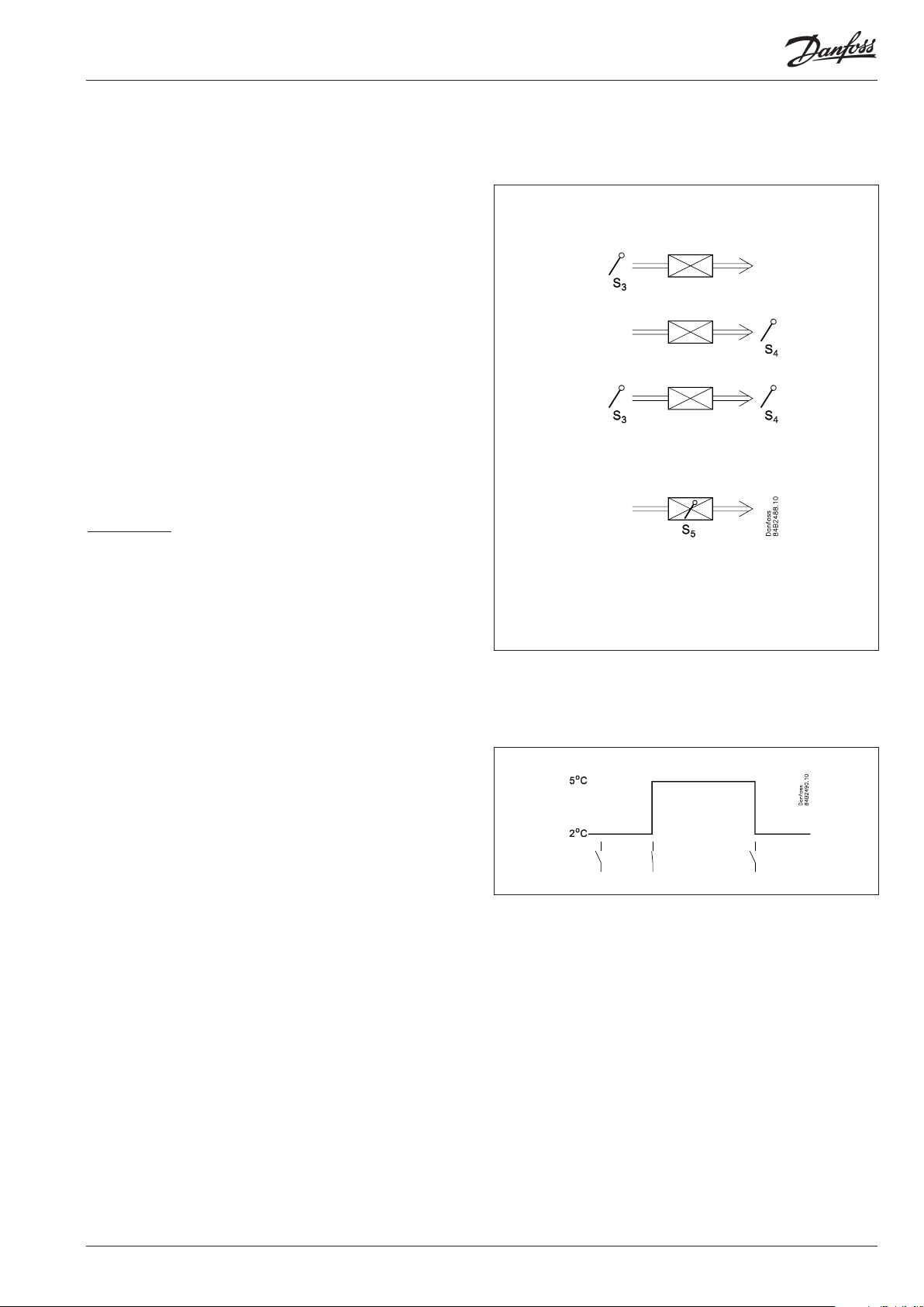
Operation
Sensors
Up to two thermostat sensors can be connected to the controller.
The relevant application determines how.
A sensor in the air before the evaporator:
This connection is primarily used when control is based on area.
A sensor in the air after the evaporator:
This connection is primarily used when refrigeration is controlled
and there is a risk of a too low temperature near the products.
A sensor before and after the evaporator:
This connection oers you the possibility of adapting the
thermostat, the alarm thermostat and the display to the relevant
application. The signal to the thermostat, the alarm thermostat
and the display is set as a weighted value between the two
temperatures, and 50% will for example give the same value from
both sensors.
The signal to the thermostat, the alarm thermostat and the display
can be set independently of one another.
Defrost sensor
The best signal concerning the evaporator’s temperature
is obtained from a defrost sensor mounted directly on the
evaporator. Here the signal may be used by the defrost function,
so that the shortest and most energy-saving defrost can take
place.
If a defrost sensor is not required, defrost can be stopped based
on time, or S4 can be selected.
Change of temperature reference
In an impulse appliance, for example, used for various product
groups. Here the temperature reference is changed easily with
a contact signal on a digital input. The signal raises the normal
thermostat value by a predened amount. At the same time the
alarm limits with the same value are displaced accordingly.
Page 4
4 Manual RS8EE202 © Danfoss 08-2010 EKC 202D
Digital inputs
There are two digital inputs both of which can be used for one of
the following functions:
- Case cleaning
- Door contact function with alarm
- Starting a defrost
- Coordinated defrost
- Change-over between two temperature references
- Retransmission of a contact’s position via data communication
Case cleaning function
This function makes it easy to steer the refrigeration appliance
through a cleaning phase. Via three pushes on a switch you
change from one phase to the next phase.
The rst push stops the refrigeration – the fans keep working
”Later”: The next push stops the fans
”Still later”: The nal push restarts refrigeration
The dierent situations can be monitored on the display.
On the network a cleaning alarm is transmitted to the system unit.
This alarm can be ”logged” so that proof of the sequence of events
is provided.
- + + °C
1 ÷ + Fan
2 ÷ ÷ O
3 + + °C
Door contact function
In cold rooms and frost rooms the door switch can turn the light
on and o, start and stop the refrigeration and give alarm if the
door has remained open for too long.
Defrost
Depending on the application you may choose between the
following defrost methods:
Natural: Here the fans are kept operating during the defrost
Electric: The heating element is activated
Brine: The valve is kept open so that the brine can ow
through the evaporator
Start of defrost
A defrost can be started in dierent ways;
Interval: Defrost is started at xed time intervals, e.g., every
eight hour
Refrigeration time:
Defrost is started at xed refrigeration time inter-
vals, in other words, a low need for
refrigeration will ”postpone” the coming defrost
Schedule: Here defrost can be started at xed times during
the day and night. However, max. 6 times
Contact: Defrost is started with a contact signal on a digital
input
Network: The signal for defrost is received from a system unit
via the data communication
S5 temp In 1:1 systems the eciency of the evaporator can
be monitored. Icing-up will start a defrost.
Manual: An extra defrost can be activated from the control ler’s lower-most button
All the mentioned methods can be used at random – if just one of
them is activated a defrost will be started.
Page 5
EKC 202D Manual RS8EE202 © Danfoss 08-2010 5
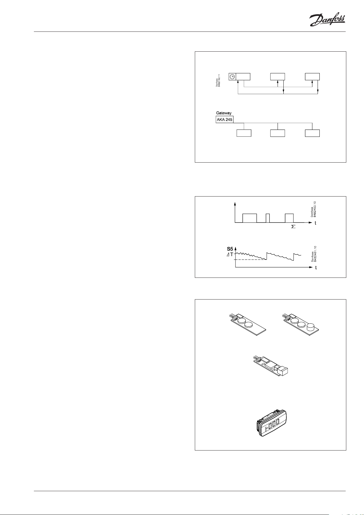
Coordinated defrost
There are two ways in which coordinated defrost can be arranged.
Either with wire connections between the controllers or via data
communication.
Wire connections
One of the controllers is dened to be the controlling unit and
a battery module may be tted in it so that the clock is ensured
backup. When a defrost is started all the other controllers will
follow suit and likewise start a defrost. After the defrost the individual controllers will move into waiting position. When all are in
waiting position there will be a change-over to refrigeration.
(If just one in the group demands defrost, the others will follow
suit).
Defrost via data communication
All controllers are tted with a data communication module,
and via the override function from a gateway the defrost can be
coordinated.
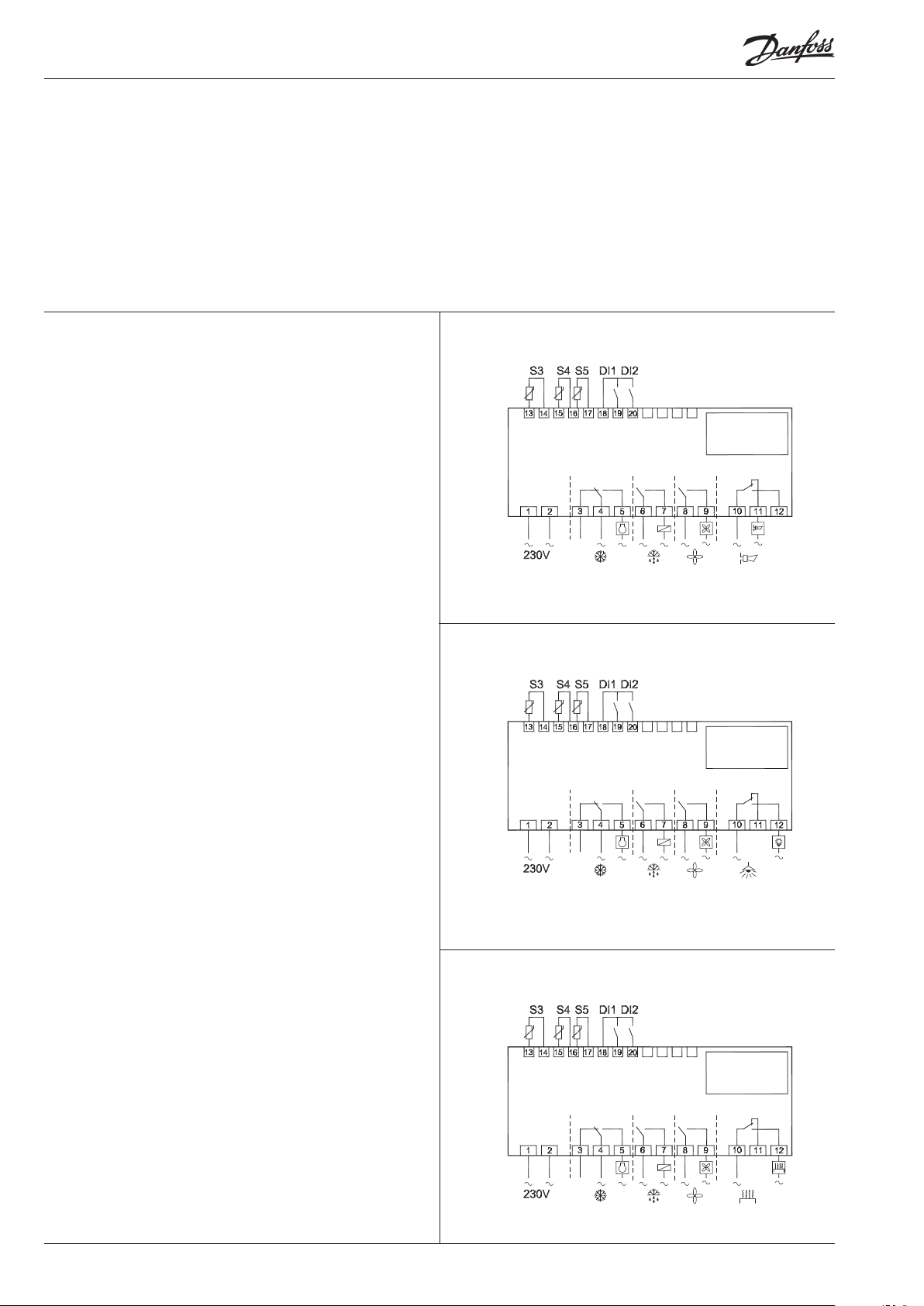
Defrost on demand
1 Based on refrigeration time
When the aggregate refrigeration time has passed a xed time,
a defrost will be started.
2 Based on temperature
The controller will constantly follow the temperature at S5.
Between two defrosts the S5 temperature will become lower
the more the evaporator ices up (the compressor operates for a
longer time and pulls the S5 temperature further down). When
the temperature passes a set allowed variation the defrost will
be started.
This function can only work in 1:1 systems
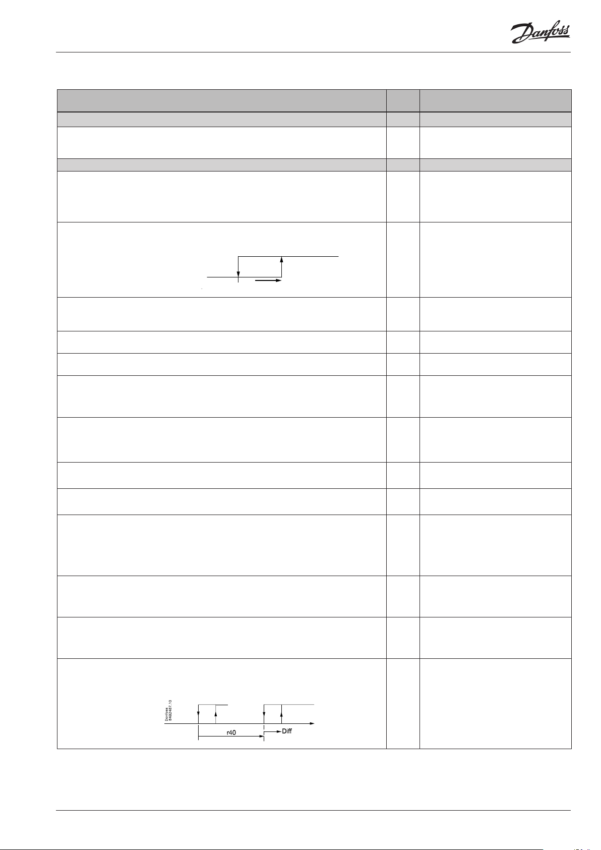
Extra module
• The controller can afterwards be tted with an insertion module
if the application requires it.
The controller has been prepared with a plug, so the module
simply has to be pushed in
- Battery module
The module guarantees voltage to the controller if the supply
voltage should drop out for more than four hours. The clock
function can thus be protected during a power failure.
- Battery and buzzer module
As above + sound buzzer
- Data communication
If you require operation from a PC, a data communication module has to be placed in the controller.
• External display
If it is necessary to indicate the temperature on the front of
refrigeration appliance, a display can be mounted. The extra display will show the same information as the controller's display,
but does not incorporate buttons for operation.
Page 6
6 Manual RS8EE202 © Danfoss 08-2010 EKC 202D
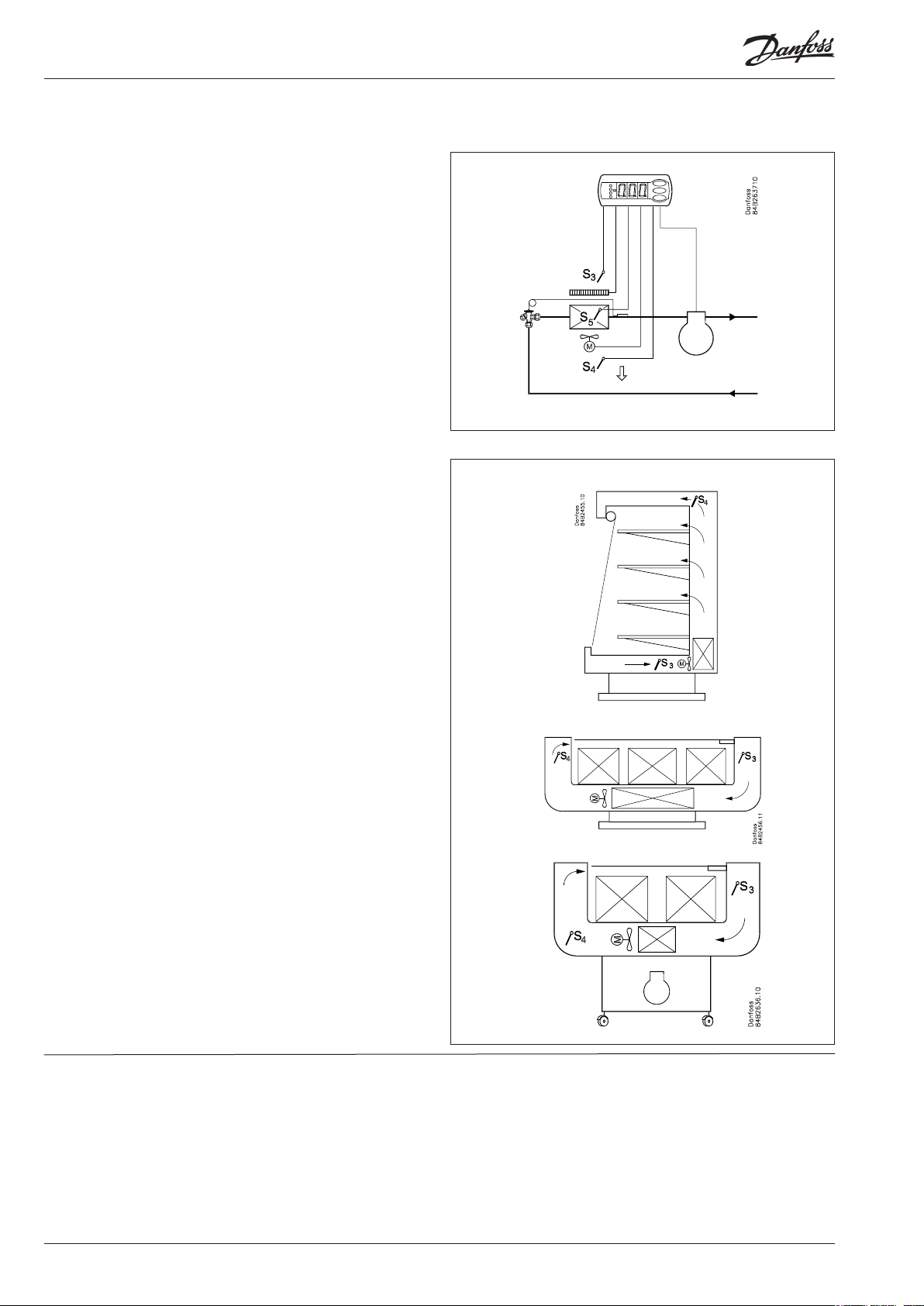
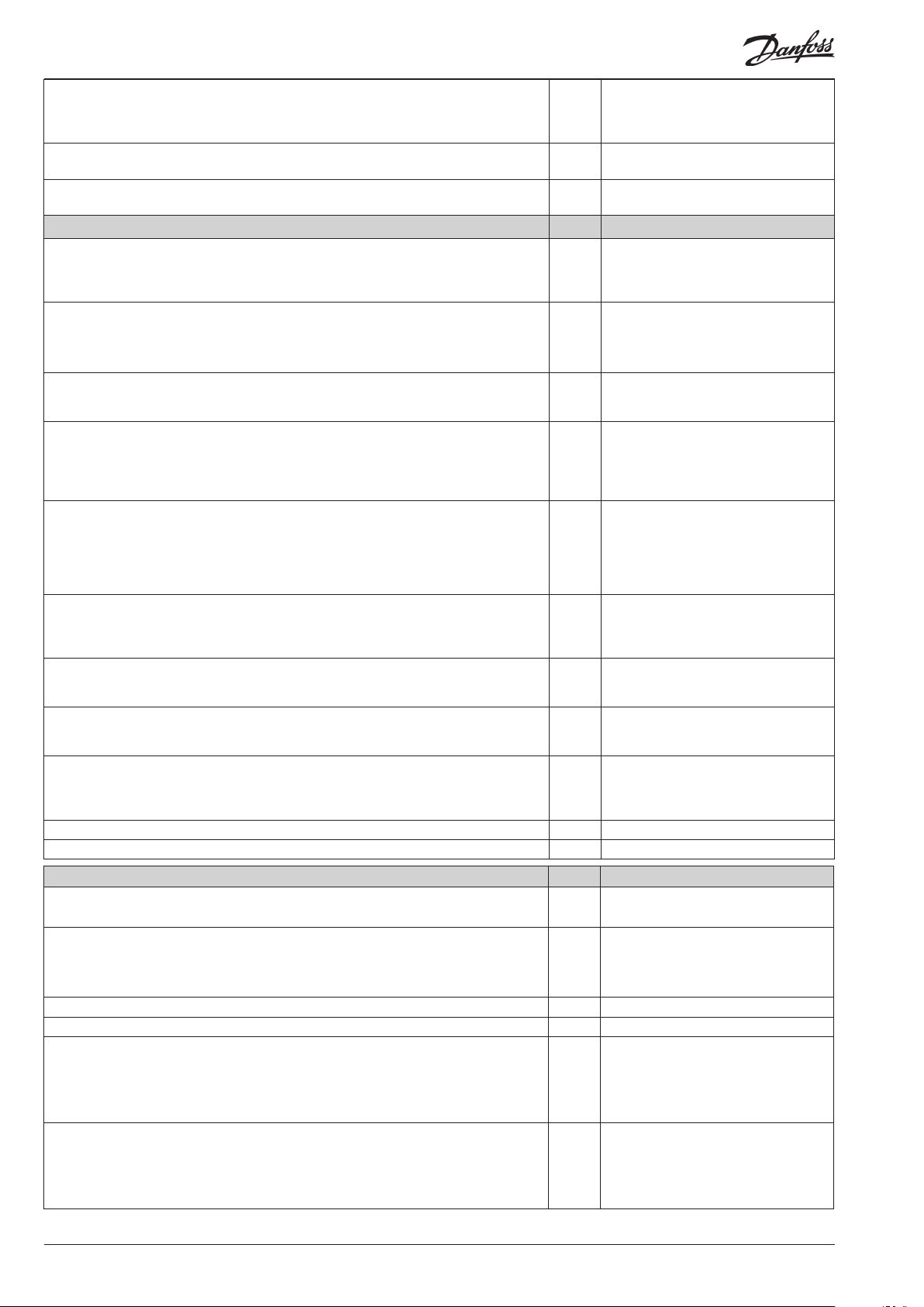
Applications
Danfoss
84B2428.12
Danfoss
84B2430.13
Danfoss
84B2429.13
Here is a survey of the controller’s eld of application.
A setting will dene the relay outputs so that the controller’s interface will be targeted the chosen application.
On page 17 you can see the relevant settings for the respective
wiring diagrams.
S3 and S4 are temperature sensors. The application will determine whether either one or the other or both sensors are to be
used. S3 is placed in the air ow before the evaporator. S4 after
the evaporator.
A percentage setting will determine according to what the
control is to be based. S5 is a defrost sensor and is placed on the
evaporator.
DI1 and DI2 are contact functions that can be used for one of the
following functions: door function, alarm function, defrost start,
external main switch, night operation, change of thermostat reference, appliance cleaning, forced refrigeration or coordinated
defrost. See the functions in settings o02 and o37.
Refrigeration control with one compressor
The functions are adapted to small refrigeration systems which
may be either refrigeration appliances or coldrooms.
The three relays can control the refrigeration, the defrost and the
fans, and the fourth relay can be used for either alarm function,
light control or rail heat control.
• The alarm function can be linked up with a contact function
from a door switch. If the door remains open longer than allowed an alarm is triggered.
• The light control can also be linked up with a contact function
from a door switch. An open door will switch on the light and
it will remain lit for two minutes after the door has been closed
again.
• The rail heat function can be used in refrigeration or freezing
appliances or on the door’s heating element for frostrooms.
The fans can be stopped during defrost and they may also follow
a door switch’s open/close situation.
There are several other functions for the alarm function as well
as the light control, rail heat control and fans. Please refer to the
respective settings.
1
2
3
Page 7
EKC 202D Manual RS8EE202 © Danfoss 08-2010 7
Survey of functions
Function Para-
meter
Normal display
Normally the temperature value from one of the two thermostat sensors S3 or S4 or a
mixture of the two measurements is displayed.
In o17 the ratio is determined.
Thermostat Thermostat control
Set point
Regulation is based on the set value plus a displacement, if applicable. The value is set
via a push on the centre button.
The set value can be locked or limited to a range with the settings in r02 and r 03.
The reference at any time can be seen in ”u28 Temp. ref”
Differential
When the temperaure is higher than the reference + the set dierential, the compressor relay will be cut in. It will cut out again when the temperature comes down to the
set reference.
Ref. Dif.
Setpoint limitation
The controller’s setting range for the setpoint may be narrowed down, so that much
too high or much too low values are not set accidentally - with resulting damages.
To avoid a too high setting of the setpoint, the max. allowable reference value must
be lowered.
To avoid a too low setting of the setpoint, the min. allowable reference value must be
increased.
Correction of the display’s temperature showing
If the temperature at the products and the temperature received by the controller are
not identical, an oset adjustment of the shown display temperature can be carried
out.
Temperature unit
Set here if the controller is to show temperature values in °C or in °F.
Correction of signal from S4
Compensation possibility through long sensor cable
Correction of signal from S3
Compensation possibility through long sensor cable
Start / stop of refrigeration
With this setting refrigeration can be started, stopped or a manual override of the
outputs can be allowed.
Start / stop of refrigeration can also be accomplished with the external switch function connected to a DI input.
Stopped refrigeration will give a ”Standby alarm”.
Night setback value
The thermostat’s reference will be the setpoint plus this value when the controller
changes over to night operation. (Select a negative value if there is to be cold accumulation.)
Selection of thermostat sensor
Here you dene the sensor the thermostat is to use for its control function. S3, S4, or a
combination of them. With the setting 0%, only S3 is used (Sin). With 100%, only S4.
Parameter by operation via data
communication
Display air (u56)
Cutout °C
r01 Dierential
r02 Max cutout °C
r03 Min cutout °C
r04 Disp. Adj. K
r05 Temp. unit
°C=0. / °F=1
(Only °C on AKM, whatever the setting)
r09 Adjust S4
r10 Adjust S3
r12 Main Switch
1: Start
0: Stop
-1: Manual control of outputs allowed
r13 Night oset
r15 Ther. S4 %
Activation of reference displacement
When the function is changed to ON the thermostat dierential will be increased by
the value in r40. Activation can also take place via input DI1 or DI2 (dened in o02 or
o37).
r39 Th. oset
Page 8
8 Manual RS8EE202 © Danfoss 08-2010 EKC 202D
Value of reference displacement
The thermostat reference and the alarm values are shifted the following number of
degrees when the displacement is activated. Activation can take place via r39 or input
DI
Alarm Alarm settings
The controller can give alarm in dierent situations. When there is an alarm all the
light-emitting diodes (LED) will ash on the controller front panel, and the alarm relay
will cut in.
Alarm delay (short alarm delay)
If one of the two limit values is exceeded, a timer function will commence. The alarm
will not become active until the set time delay has been passed. The time delay is set
in minutes.
Time delay for door alarm
The time delay is set in minutes.
The function is dened in o02 or in o37.
Time delay for cooling (long alarm delay)
This time delay is used during start-up, during defrost, immediately after a defrost.
There will be change-over to the normal time delay (A03) when the temperature has
dropped below the set upper alarm limit.
The time delay is set in minutes.
Upper alarm limit
Here you set when the alarm for high temperature is to start. The limit value is set in
°C (absolute value). The limit value will be raised during night operation. The value is
the same as the one set for night setback, but will only be raised if the value is positive.
The limit value will also be raised in connection with reference displacement r39.
Lower alarm limit
Here you set when the alarm for low temperature is to start. The limit value is set in °C
(absolute value).
The limit value will also be raised in connection with reference displacement r39.
Delay of a DI1 alarm
A cut-out/cut-in input will result in alarm when the time delay has been passed. The
function is dened in o02.
Delay of a DI2 alarm
A cut-out/cut-in input will result in alarm when the time delay has been passed. The
function is dened in o37
Signal to the alarm thermostat
Here you have to dene the ratio between the sensors which the alarm thermostat
has to use. S3, S4 or a combination of the two.
With setting 0% only S3 is used. With 100% only S4 is used
Compressor Compressor control
The compressor relay works in conjunction with the thermostat. When the thermostat calls for refrigeration will the compressor relay be operated.
Running times
To prevent irregular operation, values can be set for the time the compressor is to run
once it has been started. And for how long it at least has to be stopped.
The running times are not observed when defrosts start.
Min. ON-time (in minutes) c01 Min. On time
Min. OFF-time (in minutes) c02 Min. O time
Reversed relay function for D01
0: Normal function where the relay cuts in when refrigeration is demanded
1: Reversed function where the relay cuts out when refrigeration is demanded (this
wiring produces the result that there will be refrigeration if the supply voltage to the
controller fails).
The LED on the controller’s front will show whether refrigeration is in progress. Comp Relay
r40 Th. oset K
Night setbck
(start of night signal)
Forced cool.
(start of forced cooling)
With data communication the importance of the individual alarms can be
dened. Setting is carried out in the
“Alarm destinations” menu.
A03 Alarm delay
A04 DoorOpen del
A12 Pulldown del
A13 HighLim Air
A14 LowLim Air
A27 AI.Delay DI1
A28 AI.Delay DI2
A36 Alarm S4%
Reset alarm
EKC error
c30 Cmp relay NC
Here you can read the status of the
compressor relay, or you can forcecontrol the relay in the ”Manual
control” mode
Page 9

EKC 202D Manual RS8EE202 © Danfoss 08-2010 9
Defrost Defrost control
The controller contains a timer function that is zeroset after each defrost start.
The timer function will start a defrost if/when the interval time is passed.
The timer function starts when voltage is connected to the controller, but it is displaced the rst time by the setting in d05.
If there is power failure the timer value will be saved and continue from here when
the power returns.
This timer function can be used as a simple way of starting defrosts, but it will always
act as safety defrost if one of the subsequent defrost starts is not received.
The controller also contains a real-time clock. By means of settings of this clock and
times for the required defrost times, defrost can be started at xed times of the day.
If there is a risk of power failure for periods longer than four hours, a battery module
should be mounted in the controller.
Defrost start can also be accomplished via data communication, via contact signals or
manual start-up.
All starting methods will function in the controller. The dierent functions have to be
set, so that defrosts do not ”come tumbling” one after the other.
Defrost can be accomplished with electricity, hotgas or brine.
The actual defrost will be stopped based on time or temperature with a signal from a
temperature sensor.
Defrost method
Here you set whether defrost is to be accomplished with electricity, gas, brine or
"non".
During defrost the defrost relay will be cut in.
(*) ”refrigeration relay” is active during defrost)
Defrost stop temperature
The defrost is stopped at a given temperature which is measured with a sensor (the
sensor is dened in d10).
The temperature value is set.
d01 Def. method
0 = non
1 = El
2 = Gas *)
3= Brine *)
d02 Def. Stop Temp
Interval between defrost starts
The function is zeroset and will start the timer function at each defrost start. When
the time has expired the function will start a defrost.
The function is used as a simple defrost start, or it may be used as a safeguard if the
normal signal fails to appear.
If master/slave defrost without clock function or without data communication is used,
the interval time will be used as max. time between defrosts.
If a defrost start via data communication does not take place, the interval time will be
used as max. time between defrosts.
When there is defrost with clock function or data communication, the interval time
must be set for a somewhat longer period of time than the planned one, as the
interval time will otherwise start a defrost which a little later will be followed by the
planned one.
In connection with power failure the interval time will be maintained, and when the
power returns the interval time will continue from the maintained value.
The interval time is not active when set to 0.
Max. defrost duration
This setting is a safety time so that the defrost will be stopped if there has not already
been a stop based on temperature or via coordinated defrost.
Time staggering for defrost cutins during start-up
The function is only relevant if you have several refrigeration appliances or groups
where you want the defrost to be staggered in relation to one another. The function is
furthermore only relevant if you have chosen defrost with interval start (d03).
The function delays the interval time d03 by the set number of minutes, but it only
does it once, and this at the very rst defrost taking place when voltage is connected
to the controller.
The function will be active after each and every power failure.
Drip-off time
Here you set the time that is to elapse from a defrost and until the compressor is to
start again. (The time when water drips o the evaporator).
d03 Def Interval
(0=o)
d04 Max Def. time
d05 Time Stagg.
d06 DripO time
Delay of fan start after defrost
Here you set the time that is to elapse from compressor start after a defrost and until
the fan may start again. (The time when water is “tied” to the evaporator).
Fan start temperature
The fan may also be started a little earlier than mentioned under “Delay of fan start
after defrost”, if the defrost sensor S5 registers another allowable value than the one
set here.
d07 FanStartDel
d08 FanStartTemp
Page 10

10 Manual RS8EE202 © Danfoss 08-2010 EKC 202D
Fan cut in during defrost
Here you can set whether fan is to operate during defrost.
0: Stopped (Runs during pump down)
1: Running (stopped during "fan delay")
2: Running during pump down and defrost. After that stopped
Defrost sensor
Here you dene the defrost sensor.
0: None, defrost is based on time
1: S5
2: S4
Pumpdown delay
Set the time where the evaporator is emptied of refrigerant prior to the defrost.
Defrost on demand – aggregate refrigeration time
Set here is the refrigeration time allowed without defrosts. If the time is passed, a
defrost will be started.
With setting = 0 the function is cut out.
Defrost on demand – S5 temperature
The controller will follow the eectivity of the evaporator, and via internal calculations and measurements of the S5 temperature it will be able to start a defrost when
the variation of the S5 temperature becomes larger than required.
Here you set how large a slide of the S5 temperature can be allowed. When the value
is passed, a defrost will start.
The function can only be used in 1:1 systems when the evaporating temperature
will become lower to ensure that the air temperature will be maintained. In central
systems the function must be cut out.
With setting = 20 the function is cut out
If you wish to see the temperature at the defrost sensor, push the controller’s lower-
most button.
If you wish to start an extra defrost, push the controller’s lowermost button for four
seconds.
You can stop an ongoing defrost in the same way
The LED on the controller’s front will indicate whether a defrost is going on. Defrost Relay
Fan Fan control
Fan stopped at cut-out compressor
Here you can select whether the fan is to be stopped when the compressor is cut out
d09 FanDuringDef
d10 DefStopSens.
d16 Pump dwn del.
d18 MaxTherRunT
d19 CutoutS5Dif.
Defrost temp.
Def Start
Here you can start a manual defrost
Here you can read the defrost relay
status or you can force-control the
relay in “Manual control” mode.
Hold After Def
Shows ON when the controller is
operating with coordinated defrost.
Defrost State
Status on defrost
1= pump down / defrost
F01 Fan stop CO
(Yes = Fan stopped)
Delay of fan stop when compressor is cut out
If you have chosen to stop the fan when the compressor is cut out, you can delay the
fan stop when the compressor has stopped.
Here you can set the time delay.
Fan stop temperature
The function stops the fans in an error situation, so that they will not provide power
to the appliance. If the defrost sensor registers a higher temperature than the one set
here, the fans will be stopped. There will be re-start at 2 K below the setting.
The function is not active during a defrost or start-up after a defrost.
With setting +50°C the function is interrupted.
The LED on the controller’s front will indicate whether a defrost is going on. Fan Relay
F02 Fan del. CO
F04 FanStopTemp.
Here you can read the fan relay status,
or force-control the relay in “Manual
control” mode.
Page 11
EKC 202D Manual RS8EE202 © Danfoss 08-2010 11
Real-time clock
The controller can accommodate one insertion module which may either be a data
communication module or a battery module for the real-time clock.
The battery module is used in conjunction with the real-time clock and will keep the
clock going during lengthy power failures.
Real-time clock
You can set up to six individual times for defrost starts for each 24-hour period. There
is also a date indication used for registration of temperature measurements.
Defrost start, hour setting t01-t06
Defrost start, minute setting (1 and 11 belong together, etc.)
When all t01 to t16 equal 0 the clock will not start defrosts.
Clock: Hour setting t07
Clock: Minute setting t08
Clock: Date setting t45
Clock: Month setting t46
Clock: Year setting t47
Miscellaneous Miscellaneous
Delay of output signal after start-up
After start-up or a power failure the controller’s functions can be delayed so that overloading of the electricity supply network is avoided.
Here you can set the time delay.
Digital input signal - DI1
The controller has a digital input 1 which can be used for one of the following functions:
O: The input is not used
1) Status display of a contact function
2) Door function. When the input is open it signals that the door is open. The refrigeration and the fans are stopped. When the time setting in “A4” is passed, an alarm
will be given and refrigeration will be resumed.
3) Door alarm. When the input is open it signals that the door is open. When the time
setting in “A4” is passed, there will be alarm.
4) Defrost. The function is started with a pulse pressure. The controller will register
when the DI input is activated. The controller will then start a defrost cycle. If the
signal is to be received by several controllers it is important that ALL connections
are mounted the same way (DI to DI and GND to GND).
5) Main switch. Regulation is carried out when the input is short-circuited, and regulation is stopped when the input is put in pos. OFF.
6) Night operation. When the input is short-circuited, there will be regulation for
night operation.
7) Reference displacement when DI1 is short-circuited. Displacement with “r40”.
8) Separate alarm function. Alarm will be given when the input is short-circuited.
9) Separate alarm function. Alarm will be given when the input is opened. (For 8 and
9 the time delay is set in A27)
10) Case cleaning. The function is started with a pulse pressure. Cf. also description on
page 4.
11) Forced refrigeration when the input is short-circuited.
If the controller is built into a network with data communication, it must have an
address, and the master gateway of the data communication must then know this
address.
These settings can only be made when a data communication module has been
mounted in the controller and the installation of the data communication cable has
been nished.
This installation is mentioned in a separate document “RC8AC”.
The address is set between 1 and 240 , gateway determined o03
The address is sent to the gateway when the menu is set in pos. ON
IMPORTANT: Before you set o04, you MUST set o61. Otherwise you will be transmitting incorrect data.
Access code 1 (Access to all settings)
If the settings in the controller are to be protected with an access code you can set a
numerical value between 0 and 100. If not, you can cancel the function with setting 0.
(99 will always give you access).
Sensor type
Normally a Pt 1000 sensor with great signal accuracy is used. But you can also use a
sensor with another signal accuracy. That may either be a PTC sensor (1000 ohm at
25°C) or an NTC sensor (5000 Ohm at 25°C).
All the mounted sensors must be of the same type.
Display step
Yes: Gives steps of 0.5°
No: Gives steps of 0.1°
t11-t16
(Times cannot be set via data communication. Settings are only relevant
when there is no data communication).
o01 DelayOfOutp.
o02 DI 1 Cong.
Denition takes place with the numerical value shown to the left.
(0 = o)
DI state
(Measurement)
The DI input’s present status is shown
here. ON or OFF.
After installation of a data communication module the controller can be
operated on an equal footing with the
other controllers in ADAP-KOOL®
refrigeration controls.
o04
o05 -
o06 SensorCong
Pt = 0
PTC = 1
NTC = 2
o15 Disp. Step = 0.5
Page 12

12 Manual RS8EE202 © Danfoss 08-2010 EKC 202D
Max. standby time after coordinated defrost
When a controller has completed a defrost it will wait for a signal which tells that the
refrigeration may be resumed. If this signal fails to appear for one reason or another,
the controller will itself start the refrigeration when this standby time has elapsed.
Select signal for the display S4%
Here you dene the signal to be shown by the display.
S3, S4, or a combination of the two.
With setting 0% only S3 is used. With 100% only S4.
Digital input signal - D2
The controller has a digital input 2 which can be used for one of the following functions:
O: The input is not used.
1) Status display of a contact function
2) Door function. When the input is open it signals that the door is open. The refrigeration and the fans are stopped. When the time setting in “A4” is passed, an alarm
will be given and refrigeration resumed.
3) Door alarm. When the input is open it signals that the door is open. When the time
setting in “A4” is passed an alarm will be given.
4) Defrost. The function is started with a pulse pressure. The controller will register
when the DI input is activated. The controller will then start a defrost cycle. If the
signal is to be received by several controllers it is important that ALL connections
are mounted the same way (DI to DI and GND to GND).
5) Main switch. Regulation is carried out when the input is short-circuited, and regulation is stopped when the input is put in pos. OFF.
6) Night operation. When the input is short-circuited, there will be regulation for
night operation.
7) Reference displacement when DI2 is short-circuited. Displacement with “r40”.
8) Separate alarm function. Alarm will be given when the input is short-circuited.
9) Separate alarm function. Alarm will be given when the input is opened.
10) Case cleaning. The function is started with a pulse pressure. Cf. also description on
page 4.
11) Forced refrigeration when the input is short-circuited.
12) The input is used for coordinated defrost in conjunction with other controllers of
the same type
Configuration of light function (relay 4 in applications 2)
1) The relay cuts in during day operation
2) The relay to be controlled via data communication
3) The relay to be controlled by the door switch dened in either o02 or o37 where
the setting is selected to either 2 or 3. When the door is opened the relay will cut in.
When the door is closed again there will be a time delay of two minutes before the
light is switched o.
Activation of light relay
The light relay can be activated here, but only if dened in o38 with setting 2.
Rail heat during day operation
The ON period is set as a percentage of the time
Rail heat during night operation
The ON period is set as a percentage of the time
Rail heat cycle
The period of time for the aggregate ON time + OFF time is set in minutes
Case cleaning
The status of the function can be followed here or the function can be started manually.
0 = Normal operation (no cleaning)
1 = Cleaning with fans operating. All other outputs are O.
2 = Cleaning with stopped fans. All outputs are O.
If the function is controlled by a signal at the DI1 or DI2 input, the relevant status can
be seen here in the menu.
Selection of application
The controller can be dened in various ways. Here you set which of the 3 applications is required. On page 6 you can see a survey of applications.
This menu can only be set when regulation is stopped, i.e. “r12” is set to 0.
Access code 2 (Access to adjustments)
There is access to adjustments of values, but not to conguration settings. If the settings in the controller are to be protected with an access code you can set a numerical value between 0 and 100. If not, you can cancel the function with setting 0. If the
function is used, access code 1 (o05) must also be used.
Copy the controller’s present settings
With this function the controller’s settings can be transferred to a programming key.
The key can contain up to 25 dierent sets. Select a number. All settings except for
Application (o61) and Address (o03) will be copied. When copying has started the display returns to o65. After two seconds you can move into the menu again and check
whether the copying was satisfactory.
Showing of a negative gure spells problems. See the signicance in the Fault Message section.
o16 Max HoldTime
o17 Disp. S4%
o37 DI2 cong.
o38 Light cong
o39 Light remote
o41 Railh.ON day%
o42 Railh.ON ngt%
o43 Railh. cycle
o46 Case clean
o61 --- Appl. Mode (only output in Danfoss
only)
o64 -
o65 -
Page 13

EKC 202D Manual RS8EE202 © Danfoss 08-2010 13
Copy from the programming key
This function downloads a set of settings earlier saved in the controller. Select the
relevant number.
All settings except for Application (o61) and Address (o03) will be copied. When copying has started the display returns to o66. After two seconds you can move back into
the menu again and check whether the copying was satisfactory. Showing of a negative gure spells problems. See the signicance in the Fault Message section.
Save as factory setting
With this setting you save the controller’s actual settings as a new basic setting (the
earlier factory settings are overwritten).
Service Service
Temperature measured with S5 sensor u09 S5 temp.
Status on DI1 input. on/1=closed u10 DI1 status
Temperature measured with S3 sensor
Status on night operation (on or o) 1=closed
Temperature measured with S4 sensor u16 S4 air temp
Thermostat temperature u17 Ther. air
Read the present regulation reference u28 Temp. ref.
Status on DI2 output. on/1=closed u37 DI2 status
Temperature shown on display
Measured temperature for alarm thermostat u57 Alarm air
* Status on relay for cooling u58 Comp1/LLSV
* Status on relay for fan u59 Fan relay
* Status on relay for defrost u60 Def. relay
* Status on relay for railheat
* Status on relay for alarm u62 Alarm relay
* Status on relay for light u63 Light relay
*) Not all items will be shown. Only the function belonging to the selected applica-
tion is shown.
o66 -
o67 -
- - - Night Setback
0=Day
1=Night
u12 S3 air temp
u13 Night Cond.
u56 Display air
u61 Railh. relay
Page 14

14 Manual RS8EE202 © Danfoss 08-2010 EKC 202D
Fault message Alarms
In an error situation the LED’s on the front will ash and the alarm relay will be activated. If you push the top button in this situation you can see the alarm report in the
display. If there is more than one, simply push the button to scroll through and view
them.
There are two kinds of error reports - it can either be an alarm occurring during the
daily operation, or there may be a defect in the installation.
A-alarms will not become visible until the set time delay has expired.
E-alarms, on the other hand, will become visible the moment the error occurs.
(An A alarm will not be visible as long as there is an active E alarm).
Here are the messages that may appear: 1 = alarm
A1: High temperature alarm High t. alarm
A2: Low temperature alarm Low t. alarm
A4: Door alarm Door Alarm
A5: Information. Parameter o16 is expired Max Hold Time
A15: Alarm. Signal from DI1 input DI1 alarm
A16: Alarm. Signal from DI2 input DI2 alarm
A45: Standby position (stopped refrigeration via r12 or DI input) Standby mode
A59: Case cleaning. Signal from DI1 or DI2 input Case cleaning
Max. def time
E1: Faults in the controller EKC error
E6: Fault in real-time clock. Check the battery / reset the clock. -
E25: Sensor error on S3 S3 error
E26: Sensor error on S4 S4 error
E27: Sensor error on S5 S5 error
When copying settings to or from a copying key with functions o65 or o66, the following information may appear:
0: Copying concluded and OK
4: Copying key not correctly mounted
5: Copying was not correct. Repeat copying
6: Copying to EKC incorrect. Repeat copying
7: Copying to copying key incorrect. Repeat copying
8: Copying not possible. Order number or SW version do not match
9: Communication error and timeout
10: Copying still going on
(The information can be found in o65 or o66 a couple of seconds after copying has
been started).
Alarm destinations
The importance of the individual
alarms can be dened with a setting
(0, 1, 2 or 3)
Page 15
EKC 202D Manual RS8EE202 © Danfoss 08-2010 15
Operating status (Measurement)
The controller goes through some regulating situations where it is just waiting for
the next point of the regulation. To make these “why is nothing happening” situations
EKC State:
(Shown in all menu displays)
visible, you can see an operating status on the display. Push briey (1s) the upper button. If there is a status code, it will be shown on the display.
The individual status codes have the following meanings:
S0: Regulating 0
S1: Waiting for end of the coordinated defrost 1
S2: When the compressor is operating it must run for at least x minutes. 2
S3: When the compressor is stopped, it must remain stopped for at least x minutes. 3
S4: The evaporator drips o and waits for the time to run out 4
S10: Refrigeration stopped by main switch. Either with r12 or a DI-input 10
S11: Refrigeration stopped by thermostat 11
S14: Defrost sequence. Defrost in progress 14
S15: Defrost sequence. Fan delay — water attaches to the evaporator 15
S17: Door is open. DI input is open 17
S20: Emergency cooling *) 20
S25: Manual control of outputs 25
S29: Case cleaning 29
S30: Forced cooling 30
S32: Delay on outputs during start-up 32
Other displays:
non: The defrost temperature cannot be displayed. There is stop based on time
-d-: Defrost in progress / First cooling after defrost
PS: Password required. Set password
*) Emergency cooling will take eect when there is lack of signal from a dened S3 or S4 sensor. The regulation will continue with a registered average
cutin frequency. There are two registered values – one for day operation and one for night operation.
Warning ! Direct start of compressors *
To prevent compressor breakdown parameter c01 and c02 should be set according to suppliers requirements or in general :
Hermetic Compressors c02 min. 5 minutes
Semihermetic Compressors c02 min. 8 minutes and c01 min. 2 to 5 minutes ( Motor from 5 to 15 KW )
* ) Direct activating of solenoid valves does not require settings dierent from factory (0)
Page 16

16 Manual RS8EE202 © Danfoss 08-2010 EKC 202D
Operation
Display
The values will be shown with three digits, and with a setting you
can determine whether the temperature are to be shown in °C or
in °F.
Light-emitting diodes (LED) on front panel
The other LED’s on the front panel will light up when the belonging relay is activated.
= Refrigeration
= Defrost
= Fan running
The light-emitting diodes will ash when there is an alarm.
In this situation you can download the error code to the display
and cancel/sign for the alarm by giving the top knob a brief push.
Defrosting
A “-d-” is appears in the display during defrosting. This display will
appear for up to 15 minutes after cooling resumes.
However, the “-d-” display does not apply if:
- Temperature is reached within 15 minutes.
- Regulation is stopped via the “Main Switch”.
- A high temperature alarm is activated.
The buttons
When you want to change a setting, the upper and the lower
buttons will give you a higher or lower value depending on the
button you are pushing. But before you change the value, you
must have access to the menu. You obtain this by pushing the
upper button for a couple of seconds - you will then enter the column with parameter codes. Find the parameter code you want to
change and push the middle buttons until value for the parameter
is shown. When you have changed the value, save the new value
by once more pushing the middle button.
Examples
Set menu
1. Push the upper button until a parameter r01 is shown
2. Push the upper or the lower button and nd that parameter you
want to change
3. Push the middle button until the parameter value is shown
4. Push the upper or the lower button and select the new value
5. Push the middle button again to freeze the value.
Cutout alarm relay / receipt alarm/see alarm code
• Push short the upper button
If there are several alarm codes they are found in a rolling stack.
Push the uppermost or lowermost button to scan the rolling
stack.
Set temperature
1. Push the middle button until the temperature value is shown
2. Push the upper or the lower button and select the new value
3. Push the middle button again to conclude the setting.
Reading the temperature at defrost sensor
• Push short the lower button
Manuel start or stop of a defrost
• Push the lower button for four seconds.
Get a good start
With the following procedure you can start regulation very quickly:
1 Open parameter r12 and stop the regulation (in a new and not
previously set unit, r12 will already be set to 0 which means
stopped regulation.)
2 Select electric connection based on the drawings on page 6
3 Open parameter o61 and set the electric connection number in
it
4 Open parameter r12 and start the regulation
5 Go through the survey of factory settings. The values in the grey
cells are changed according to your choice of settings. Make any
necessary changes in the respective parameters.
6 For network. Set the address in o03 and then transmit it to the
gateway/system unit with setting o04.
Page 17

EKC 202D Manual RS8EE202 © Danfoss 08-2010 17
Menu survey
Parameters
Function Codes 1 2 3
Normal operation
Temperature (set point) --- -50.0°C 50.0°C 2.0°C
Thermostat
Dierential *** r01 0.0 K 20.0K 2.0 K
Max. limitation of setpoint setting *** r02 -49.0°C 50°C 50.0°C
Min. limitation of setpoint setting *** r03 -50.0°C 49.0°C -50.0°C
Adjustment of temperature indication r04 -20.0 K 20.0 K 0.0 K
Temperature unit (°C/°F) r05 °C °F °C
Correction of the signal from S4 r09 -10.0 K +10.0 K 0.0 K
Correction of the signal from S3 r10 -10.0 K +10.0 K 0.0 K
Manual service, stop regulation, start regulation (-1, 0, 1) r12 -1 1 0
Displacement of reference during night operation r13 -10.0 K 10.0 K 0.0 K
Denition and weighting, if applicable, of thermostat sensors - S4% (100%=S4,
0%=S3)
Activation of reference displacement r40 r39 OFF ON OFF
Value of reference displacement (activate via r39 or DI) r40 -50.0 K 50.0 K 0.0 K
Alarm
Delay for temperature alarm A03 0 min 240 min 30 min
Delay for door alarm *** A04 0 min 240 min 60 min
Delay for temperature alarm after defrost A12 0 min 240 min 90 min
High alarm limit *** A13 -50.0°C 50.0°C 8.0°C
Low alarm limit *** A14 -50.0°C 50.0°C -30.0°C
Alarm delay DI1 A27 0 min 240 min 30 min
Alarm delay DI2 A28 0 min 240 min 30 min
Signal for alarm thermostat. S4% (100%=S4, 0%=S3) A36 0% 100% 100%
Compressor
Min. ON-time c01 0 min 30 min 0 min
Min. OFF-time c02 0 min 30 min 0 min
Compressor relay 1 must cutin and out inversely
(NC-function)
Defrost
Defrost method (none/EL/GAS/BRINE) d01 no bri EL
Defrost stop temperature d02 0.0°C 25.0°C 6.0°C
Interval between defrost starts d03 0 hours 48 hours 8 hours
Max. defrost duration d04 0 min 180 min 45 min
Displacement of time on cutin of defrost at start-up d05 0 min 240 min 0 min
Drip o time d06 0 min 60 min 0 min
Delay for fan start after defrost d07 0 min 60 min 0 min
Fan start temperature d08 -15.0°C 0.0°C -5.0°C
Fan cutin during defrost
EL-diagram
number (page 6)
r15 0% 100% 100%
c30 0
d09 0 2 1
Min.-value Max.-value
OFF
1
ON
SW = 2.2x
Factory set-
ting
0
OFF
0: Stopped
1: Running
2: Running during pump down and defrost
Defrost sensor (0=time, 1=S5, 2=S4) d10 0 2 0
Pump down delay d16 0 min 60 min 0 min
Max. aggregate refrigeration time between two defrosts d18 0 hours 48 hours 0 hours
Defrost on demand - S5 temperature’s permitted variation during frost build-up.
On central plant choose 20 K (=o)
Fan
Fan stop at cutout compressor F01 no yes no
Delay of fan stop F02 0 min 30 min 0 min
Fan stop temperature (S5) F04 -50.0°C 50.0°C 50.0°C
Real time clock
Six start times for defrost.
Setting of hours.
0=OFF
Six start times for defrost.
Setting of minutes.
0=OFF
Clock - Setting of hours *** t07 0 hours 23 hours 0 hours
Clock - Setting of minute *** t08 0 min 59 min 0 min
Clock - Setting of date *** t45 1 31 1
Clock - Setting of month *** t46 1 12 1
Clock - Setting of year *** t47 0 99 0
Miscellaneous
Delay of output signals after start-up o01 0 s 600 s 5 s
Input signal on DI1. Function:
0=not used. 1=status on DI1. 2=door function with alarm when open. 3=door
alarm when open. 4=defrost start (pulse-pressure). 5=ext.main switch. 6=night
operation 7=change reference (activate r40). 8=alarm function when closed.
9=alarm function when open. 10=case cleaning (pulse pressure). 11=forced
cooling.
Network address o03 0 240 0
On/O switch (Service Pin message)
IMPORTANT! o61 must be set prior to o04
Access code 1 (all settings) o05 0 100 0
Used sensor type (Pt /PTC/NTC) o06 Pt ntc Pt
Display step = 0.5 (normal 0.1 at Pt sensor) o15 no yes no
Max hold time after coordinated defrost o16 0 min 60 min 20
Select signal for display view. S4% (100%=S4, 0%=S3) o17 0% 100% 100%
d19 0.0 K 20.0 k 20.0 K
t01-
t06
t11-
t16
o02 1 11 0
o04 OFF ON OFF
0 hours 23 hours 0 hours
0 min 59 min 0 min
Actual set-
ting
Page 18

18 Manual RS8EE202 © Danfoss 08-2010 EKC 202D
Input signal on DI2. Function:
(0=not used. 1=status on DI2. 2=door function with alarm when open. 3=door
alarm when open. 4=defrost start (pulse-pressure). 5=ext. main switch 6=night
operation 7=change reference (activate r40). 8=alarm function when closed.
9=alarm function when open. 10=case cleaning (pulse pressure). 11=forced cooling.). 12=coordinated defrost)
Conguration of light function (relay 4)
1=ON during day operation. 2=ON / OFF via data communication. 3=ON follows
the DI-function, when DI is selected to door function or to door alarm
Activation of light relay (only if o38=2) o39 OFF ON OFF
Rail heat On time during day operations o41 0% 100% 100
Rail heat On time during night operations o42 0% 100% 100
Rail heat period time (On time + O time) o43 6 min 60 min 10 min
Case cleaning. 0=no case cleaning. 1=Fans only. 2=All output O. *** o46 0 2 0
Selection of EL diagram. See overview page 6 * o61 1 2 3 1 3 1
Access code 2 (partly access) *** o64 0 100 0
Save the controllers present settings to the programming key. Select your own
number.
Load a set of settings from the programming key (previously saved via o65 function)
Replace the controllers factory settings with the present settings o67 OFF On OFF
Service
Status codes S0-S33
Temperature measured with S5 sensor *** u09
Status on DI1 input. on/1=closed u10
Temperature measured with S3 sensor *** u12
Status on night operation (on or o) 1=closed *** u13
Temperature measured with S4 sensor *** u16
Thermostat temperature u17
Read the present regulation reference u28
Status on DI2 output. on/1=closed u37
Temperature shown on display u56
Measured temperature for alarm thermostat u57
Status on relay for cooling ** u58
Status on relay for fan ** u59
Status on relay for defrost ** u60
Status on relay for railheat ** u61
Status on relay for alarm ** u62
Status on relay for light ** u63
*) Can only be set when regulation is stopped (r12=0)
**) Can be controlled manually, but only when r12=-1
***) With access code 2 the access to these menus will be limited
Factory setting
If you need to return to the factory-set values, it can be done in this way:
- Cut out the supply voltage to the controller
- Keep both buttons depressed at the same time as you recon nect the supply voltage
o37 0 12 0
o38 1 3 1
o65 0 25 0
o66 0 25 0
Page 19

EKC 202D Manual RS8EE202 © Danfoss 08-2010 19
Override
The controller contains a number of functions that can be used together with the override function in the master gateway / System
Manager.
Function via data communication
Start of defrosting Defrost control
Coordinated defrost Defrost control - - - HoldAfterDef
Night setback Day/night control
Light control Day/night control
Functions to be used in the gateway’s
override function
Time schedule
Time schedule
Time schedule
Used parameter in EKC 202D
- - - Def.start
u60 Def.relay
- - - Night setbck
o39 Light Remote
Ordering
Type Function Voltage supply Code no.
230 V a.c. 084B8536
115 V a.c. 084B8537
EKC 202D
Refrigeration controller without data
communication but prepared for mounting of one module
EKA 178A
EKA 179A Data communication module
EKA 181A Battery and buzzer module that will protect the clock in case of
EKA 181C
EKA 182A Copy key EKC - EKC 084B8567
EKA 163A External display 084B8562
Data communication module
MOD-bus
LON RS 485
lengthy power failure
Battery module that will protect the clock in case of lengthy power
failure
084B8564
084B8565
084B8566
084B8577
Page 20

20 Manual RS8EE202 © Danfoss 08-2010 EKC 202D
Connections
(115 V a.c.)
Power supply
230 V a.c. (115 V version available)
Sensors
S3 and S4 are thermostat sensors.
A setting determines whether S3 or S4 or both of them are to be
used.
S5 is a defrost sensor and is used if defrost has to be stopped
based on temperature.
Digital On/Off signals
A cut-in input will activate a function. The possible functions are
described in menus o02 and o37.
External display
Connection of display type EKA 163A.
Relays
The general uses are mentioned here. See also page 6 where the
dierent applications are shown.
DO1: Refrigeration. The relay will cut in when the controller demands refrigeration
DO2: Defrost. The relay will cut in when defrost is in progress
DO3: Fans
The relay will cut in when the fans have to operate
DO4: For either alarm, rail heat or light
Alarm: Cf. diagram. The relay is cut in during normal operation and cuts out in alarm situations and when the controller
is dead (de-energised)
Rail heat: The relay cuts in when rail heat is to operate
Light: The relay cuts in when the light has to be switched on
Data communication
The controller is available in several versions where data communication can be carried out with one of the following systems:
MOD-bus or LON-RS485.
If data communication is used, it is important that the installation
of the data communication cable is performed correctly.
See separate literature No. RC8AC…
Electric noise
Cables for sensors, DI inputs and data communication must be
kept separate from other electric cables:
- Use separate cable trays
- Keep a distance between cables of at least 10 cm
- Long cables at the DI input should be avoided
Coordinated defrost via
cable connections
Coordinated defrost via
data communication
The following controllers can be connected
up in this way:
EKC 204A, EKC 202D
Refrigeration is resumed when all
controllers have “released” the signal for
defrost.
Page 21

EKC 202D Manual RS8EE202 © Danfoss 08-2010 21
Data
Supply voltage
Sensors 3 pcs o
either
Accuracy
Display LED, 3-digits
External display EKA 163A
Digital inputs
Electrical connection cable
Relays*
Environments
Density
Escapement
reserve for the
clock
Approvals
* DO1 and DO2 are 16 A relays. DO3 and DO4 are 8 A relays. Max. load must be keept.
** Gold plating ensures make function with small contact loads
*** UL-approval based on 30000 couplings
230 V a.c.(or 115 V version) +10/-15 %. 2.5 VA,
50/60 Hz
Pt 1000 or
PTC (1000 ohm / 25°C) or
NTC-M2020 (5000 ohm / 25°C)
Measuring range -60 to +99°C
Controller
Pt 1000 sensor
Signal from contact functions
Requirements to contacts: Gold plating
Cable length must be max. 15 m
Use auxiliary relays when the cable is longer
Max.1.5 mm2 multi-core cable
DO1.
Refrigeration
DO2. Defrost 10 (6) A
DO3. Fan 6 (3) A
DO4. Alarm, light
or rail heat
0 to +55°C, During operations
-40 to +70°C, During transport
20 - 80% Rh, not condensed
No shock inuence / vibrations
IP 65 from front.
Buttons and packing are imbedded in the front.
4 hours
EU Low Voltage Directive and EMC demands re CEmarking complied with
LVD tested acc. EN 60730-1 og EN 60730-2-9, A1, A2
EMC tested acc. EN50082-1 og EN 60730-2-9, A2
±1 K below -35°C
±0.5 K between -35 to +25°C
±1 K above +25°C
±0.3 K at 0°C
±0.005 K per grad
CE
(250 V a.c.)
10 (6) A
4 (1) A
Min. 100 mA**
UL ***
(240 V a.c.)
10 A Resistive
5FLA, 30LRA
10 A Resistive
5FLA, 30LRA
6 A Resistive
3FLA, 18LRA
131 VA Pilot
duty
4 A Resistive
131 VA Pilot
duty
Page 22

22 Manual RS8EE202 © Danfoss 08-2010 EKC 202D
Page 23

EKC 202D Manual RS8EE202 © Danfoss 08-2010 23
Page 24

Danfoss can accept no responsibility for possible errors in catalogues, brochures and other printed material. Danfoss reserves the right to alter its products without notice. This also applies to products
already on order provided that such alternations can be made without subsequential changes being necessary in specications already agreed.
All trademarks in this material are property of the respecitve companies. Danfoss and Danfoss logotype are trademarks of Danfoss A/S. All rights reserved.
24 Manual RS8EE202 © Danfoss 08-2010 EKC 202D
FC-SPMC
 Loading...