

Page 1

INSTRUCTIONS
Thermostat EFET 520
Function:
Thermostat EFET 520 is an electronic thermostat with a
built-in two-pole switch. 10 A.
Thermostat EFET 520 is used with a fl oor sensor or with
remote room sensor.
Thermostat EFET 520 is delivered with a 5ºC night
set-back element. NB! The night set-back element can be
activated by applying voltage to clamp 5.
Installation:
1. Thermostat EFET 520 can be mounted in a separate
box or in a combination system.
2. Detach the thermostat cover from the electronic part
by fi rst removing the setting button with a small screwdriver, and then removing the screw underneath, see
fi g. 1.
3. The contact arm must be in position 0 when disassembling and assembling the thermostat.
After reassembly the arm should be easily moved.
4. If the fl oor sensor is used it must be placed in a 16 mm
installation pipe which is sealed at the end.
5. Wire connection according to circuit diagram.
6. Make sure that the setting button can be turned after
remounting of thermostat cover.
NB! It is possible to preset a fi xed temperature range,
see fi g. 2.
7. Set the thermostat at the desired temperature.
Fine adjustment is necessary after a certain period.
8. To avoid cracks in the concrete fl oor you must make
sure that the fl oor is completely hardened before the
heating system is switched on.
9. 2-4 days will pass from switching on the heating
system until the temperature has stabilized at the set
value.
08095692 - 01.01 09-2003
Page 2
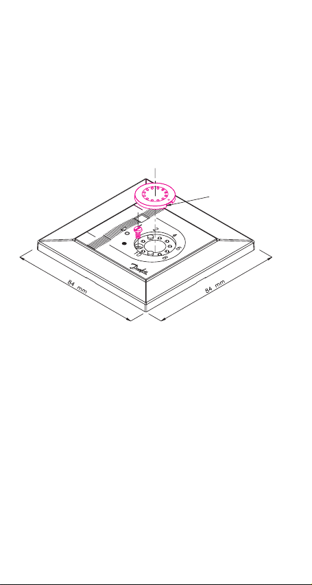
Mark for dismounting
the tuner
520
Fig. 1
When dismounting the thermostat cover, tip out the setting
button with a screwdriver. Remove the screw under the cover.
2
Page 3
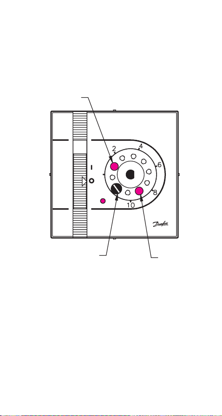
Min.
520
Screw Max.
Fig. 2
The temperature range can be locked by moving the riders to
the desired position.
3
Page 4

Fig. 3
4
Timer
NTC sensor
Max. 10 A
Page 5

Trouble-shooting
Control of functioning:
If heat is not turned on by activating the thermostat, check
the residual current device (RCD) and fuses before contacting
an authorized electrician.
Trouble-shooting chart:
Reserved for the electrician!
Control of functioning:
• Check mains voltage on clamps 1 and 2.
• Tighten up clamps 3 and 4. Measure the resistance in the
heating cable and calculate the output:
2
52900
U
P = = W (at 230 V ~)
R R
• From the calculated output the heating cable type can be
determined by looking it up in your XXX catalogue.
• If sensor wire clamps 6 and 7 are removed the indicator
should turn red and the termostat should be switched on.
If not, the thermostat is defect.
• If sensor wire clamps 6 and 7 are short-circuited, the
indicator should turn green and the thermostat should be
switched off. If not, the thermostat is defect.
• Measuring of sensor with ohmmeter should give a stable
resistance compared to the ambient temperature – see
technical data chart.
• When the voltage is disconnected the relay contact must
be open and the diode switched off.
5
Page 6

Technical data
Te mperature range +5ºC to +45°C
Voltage 180 - 250 V ~ 50 Hz
Load 250 V ~ 10 A
Load cos ϕ = 0,3 max. 1 A
Hysteresis 0.5ºC
Night set-back 5ºC
Operating temperature –10ºC to +40°C
Moisture proof IP 30
Sensing unit NTC 15 kOhm at 25ºC
–10°C 66 kOhm
Sensing values 0°C 42 kOhm
+25°C 15 kOhm
+50°C 6 kOhm
LED Indicator
No light The system is off.
Red Heat is on but the preset
temperature is not reached yet.
Green The preset temperature is
reached and heat is off.
6
Page 7

The Danfoss Warranty:
You have purchased a
Danfoss EFET 520
thermostat, which forms an
integrated part of a Danfoss
system, which we are certain
will improve your home
comfort and economy.
Danfoss provides com plete
heating solutions with
Danfoss heating cables
or Danfoss heating mats,
ther mo stats and fast fi tting
bands.
If, however, contrary to all
ex pec ta tions, a problem
should occur with your
heating system, we at
Danfoss, with manufacturing
units in Denmark, are, as
European Union suppliers,
subject to general product
liability rules, as stated in
Directive 85/374/CEE, and
all relevant national laws
which implies that:
Danfoss provides a warranty
for Danfoss heating cables
and Danfoss heating mats
for a 10 year period and all
other Danfoss prod ucts for a
2 year period against de fects
in material and production.
The guarantee is granted on
the conditions that the WAR RAN TY CER TIF I CATE on the
overleaf is fi lled out properly
in ac cor dance to in struc tions and that the defect is
inspected by, or pre sent ed
to, Danfoss or authorised
Danfoss distributor.
Please note, that the
wording of the WARRANTY
CER TIF I CATE must be
provided in english or local
lan guage with the ISO code
for your country in the upper
left corner of the front page
of the installation in struc tion
in order to release the
warranty.
The obligation of Danfoss
will be to repair or supply
a new unit, free of charge
to the customer, whitout
secondary charges linked
to repairing the unit. In case
of defective ther mo stats,
Danfoss reserves the right to
repair the unit free of charge
and without unreasonable
delay to the customer.
The Danfoss warranty only
covers connections made
by authorised electricians
and installations per formed
in accordance with the
installation instruction,
and does not cover faults
caused by in cor rect designs
supplied by others, misuse,
damage caused by others,
or in cor rect in stal la tion or
any sub se quent damage,
that may occur. If Danfoss is
required to inspect or repair
any defects caused by any
of the above, then all work
will be fully charge able.
The Danfoss warranty is
void, if payment of the
equipment is in default.
At all times, we at Danfoss
will respond honestly,
effi ciently and promtly to all
queries and resonable requests from our customers.
The above mentioned
warranty concerns product
liability whereas matters in
relation to legislation on sale
of goods shall be referred to
national law.
7
Page 8

Warranty Certifi cate
The Danfoss Warranty is granted to:
Name:
Address:
Postal code:
Phone:
In order to obtain the Danfoss Warranty, the following must be
Please Observe!
carefully fi lled in. See other conditions on the overleaf.
Electrical Installation by:
Installation date:
Ty pe of thermostat: Production code:
Suppliers Stamp:
8
08095692 - 01.01 09-2003
 Loading...