

Page 1
Technical Paper
Danfoss eTRV E-error codes description
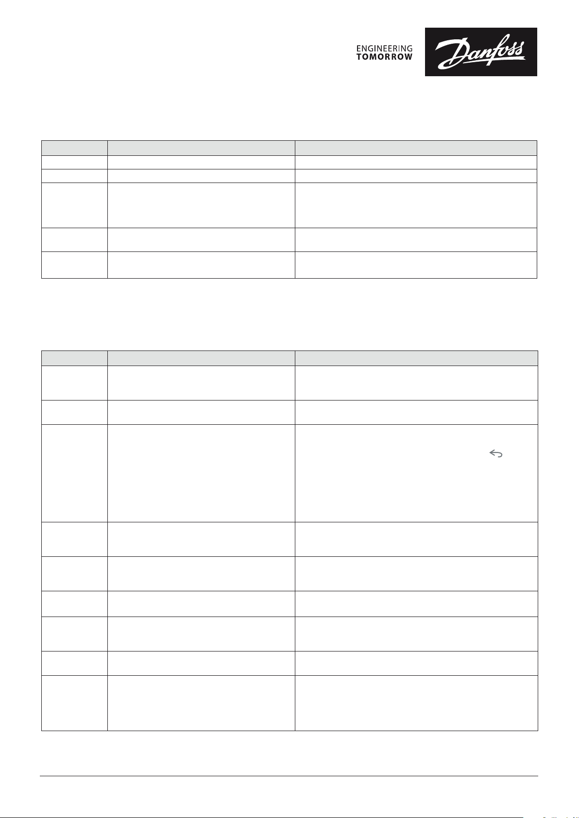
Alarm code Problem Solution
E1 Top PCB sensor error The temperature sensor is damaged, return to a dealer
E2 Side PCB sensor error The temperature sensor is damaged, return to a dealer
E6 Motor error Motor jammed, try to remove/insert battery, if the error
persists try to reset, if still no positive result return to a dealer.
Note! The eTRV will retry after 20 min.
The error code will be on the display, until cleared by the controller
E8 Invalid communication (Bluetooth/ZigBee) Try to remove/insert battery, if the error persists try to reset, if
still no positive result return to a dealer.
E9 Valve closing ability It looks like the valve cannot be closed correctly, please check
the installation
Danfoss Icon™ E-error codes description
Alarm code Problem Solution
Er03 You have set-up a cooling application that
requires a reference room thermostat to be
appointed.
Er05 Communication lost to Radio Module. Please check that the cable is properly connected in the Radio
Er06 Communication lost to room thermostat. Identify the room thermostat by looking at the ashing
Er07 Communication lost to Slave Controller. If wireless, check Radio Module connection to Danfoss
Er08 Communication lost from Slave to Master
Controller.
Er10 Communication lost to Repeater. Check that the repeater is plugged into outlet / has not been
Er11 Communication lost to Expansion Module. Check that Expansion Module is slidded fully into place.
Er12 Actuator defective.
The defective actuator output is ashing.
Er14 A Danfoss Icon™ Master Conroller cannot
be included as (become) a Slave Controller
because one or more room thermostats,
repeaters or Danfoss Icon™ Master Controller
24V have allready been included.
Please go to the thermostat in the desired reference room and
enter the thermostat installer menu. Set thermostat to ON in
ME.6 “reference room thermostat”.
Module and Danfoss Icon™ Master Controller 24V.
outputs on the Danfoss Icon™ Master Controller 24V, or look
at the thermostats. Wake up thermostat, then press on the
thermostat. Faling thermostat will say “NET ERR”.
In some cases it is necessary to add a repeater to establish a
better wireless communication between the Master Controller
and Thermostat.
Replace batteries on room thermostat and perform a network
test (activate NET TEST in menu ME.3 on room thermostat).
Icon™ Master Controller 24V. If wired system, check the wire
connecting the controllers.
If wireless, check Radio Module connection to Danfoss
Icon™ Master Controller 24V. If wired system, check the wire
connecting the controllers.
removed and outlet is ON.
Note! The Master controller must be turn o and on again in order
to register the expansion module.
Replace actuator.
This Danfoss Icon™ Master Controller 24V has to be factory
reset to become a Slave Controller. (See description in chapter
”Reset or replace a Danfoss Icon™ Master Controller”).
© Danfoss | FEC | 2022.03
AM398144307765en-000104 | 1
Page 2
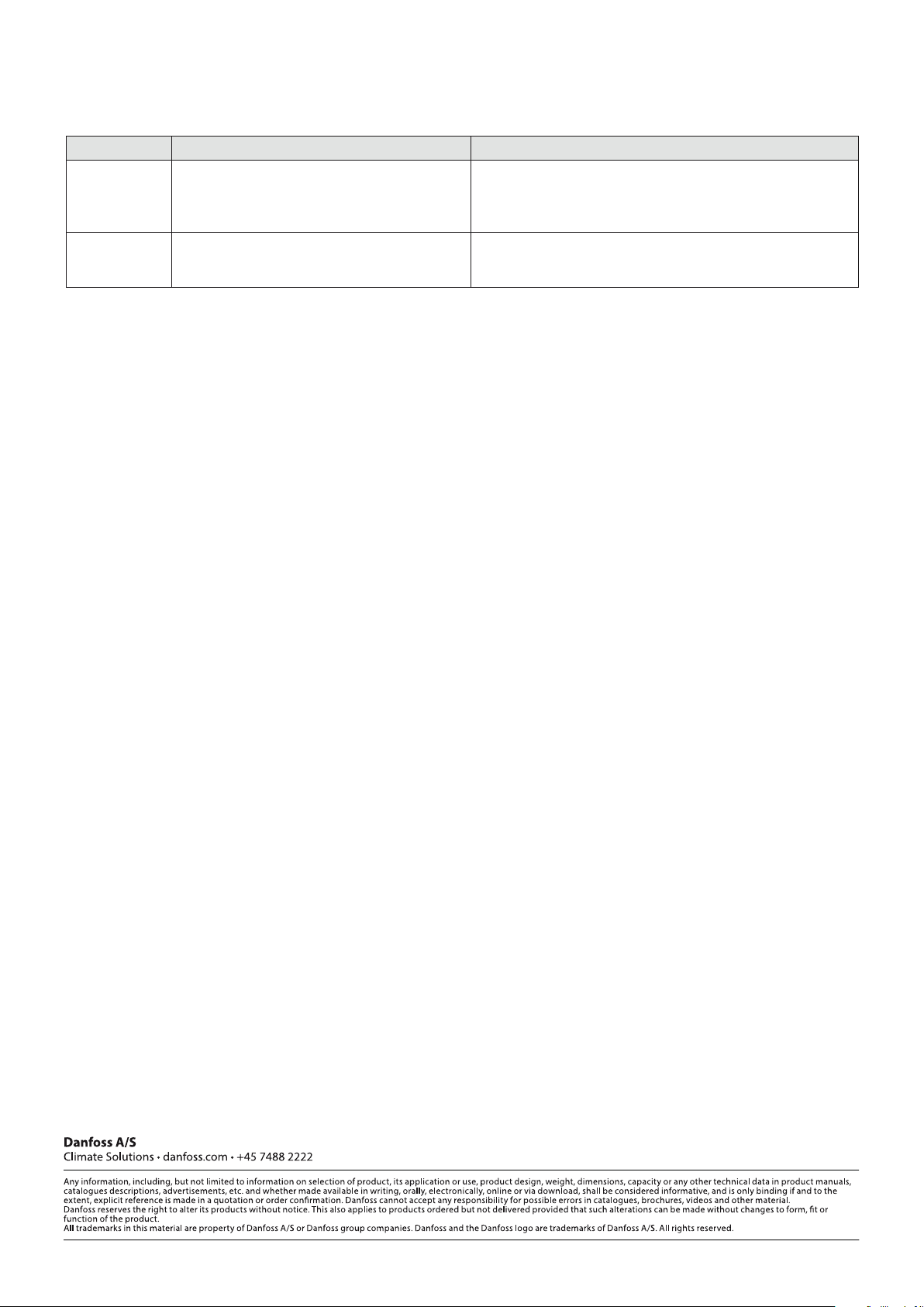
Alarm code Problem Solution
Er16 This application requires a specic actuator
output to be available.
Er17 External PT1000 sensor not tted, or defective. Check sensor and replace if necessary
You have already assigned this output to a room thermostat, or
the output has not yet had an actuator tted. Please uninstall
RT from TWA, it must be available to the application chosen (or
t actuator – if this was not yet done).
Note! Remember to ensure that the Master Controller is connected
due to risk of electric shock.
© Danfoss | FEC | 2022.03
AM398144307765en-000104 | 2
 Loading...